ups web/snmp manager - generex.de · v.: 2.0.5 2018-05-24 / fw1.68 5 introduction thank you for...
TRANSCRIPT
v.: 2.0.5 2018-05-24 / FW1.68
1
CS141 User Manual English
UPS WEB/SNMP MANAGER
v.: 2.0.5 2018-05-24 / FW1.68
2
Copyright Statement for Intellectual Property and Confidential Information
The information contained in this manual is non-conditional and may be changed without due notice. Although Generex has
attempted to provide accurate information within this document, Generex assumes no responsibility for the accuracy of this
information.
Generex shall not be liable for any indirect, special, consequential, or accidental damage including, without limitations, lost
profits or revenues, costs of replacement goods, loss or damage to data arising out of the use of this document.
Generex the manufacturer of the BACS products undertakes no obligations with this information. The products that are
described in this brochure are given on the sole basis of information to its channel partners for them to have a better
understanding of the Generex products.
Generex allows its channel partners to transfer information contained in this document to third persons, either staff within their
own Company or their own customers, either electronically or mechanically, or by photocopies or similar means. Generex states
that the content must not be altered or adapted in any way without written permission from Generex.
It is agreed that all rights, title and interest in the Generex’s trademarks or trade names (whether or not registered) or goodwill
from time to time of Generex or in any intellectual property right including without limitation any copyright, patents relating to the
Products, shall remain the exclusive property of Generex.
Generex will undertake to deal promptly with any complaints about the content of this document. Comments or complaints about
the document should be addressed to Generex Systems GmbH.
Copyright of the European Union is effective (Copyright EU).
Copyright (c) 1995-2017 GENEREX GmbH, Hamburg, Germany. All rights reserved.
v.: 2.0.5 2018-05-24 / FW1.68
3
Table of Contents Introduction Differences to the CS121 5 Model Overview 6 Delivery notes 7 Function overview CS141 8 Hardware Layout 9 Interface Assignment 11 External D-SUB 9-pin male 12 Network integration of the CS141 13 Initial Configuration Preparation at the CS41 14 Preparing the Workstation 14 DHCP 15 Finding CS141 in networks 16 Netfinder 16 Differences in operation modes 17 Before you start Installation examples 18 Required Ports 20 CS141 Basic settings
User Management 21 Setup Wizard 22 IP-address settings and hostname 23 Location and contzact settings 24 Provided services 25 Date and time 27 User management 28 System overview 29 Switching to operational mode 31
System notification
Email settings 32 Advanced Mail Options 33 Testing Mail Settings 33 The most common error message 34 Modbus 34 Email traps 34 SNMP Agent 35
UPS Configuration
General COM Port Settings 37 The pipe through function 38 Automatic UPS search feature 39 Configuration of a UPS 39 UPS monitoring screen 41 UPS functions 42 UPS event handling 44 Battery Health Level (%) feature 45 RFC 1628 UPS Interface 45 Difference between APC Smart Network and RFC 1628 45 Managing jobs 46 Available jobs 46 UPS Shutdown definition 46 How to configure a job 48 Time management of jobs 49 Adding several jobs 49 Deleting jobs 50 Counter Events 50
Custom Thresholds
What are Custom Thresholds 51 Difference Warning/Alarm Levels 51 Example scenario: Custom Thresholds 51 Exemplary excerpt: Custom Thresholds 53 Tutorial: Custom thresholds 54
v.: 2.0.5 2018-05-24 / FW1.68
4
RCCMD What is RCCMD 55 Available RCCMD Commands 55 Configuration of RCCMD 55 Setting an RCCMD Job 56 Setting the IP address for RCCMD 56 Timing for RCCMD jobs 57 variables for RCCMD traps 58
Sensors and devices
General COM Port Settings 60 SM_T_H_COM Standalone Sensor 60 Setting up a sensor 61 Sensor monitoring screen 62 Event handling for sensors 62 Sensor related system events 62 Setting up a job 63 Sensor Manager 63 Alarm device / buzzer 65 GSM modem 68 CON_AUX4 and CON_R_AUX4 71
Scheduler
How the scheduler works 74 Setting up scheduled Jobs 74
Web Server
safety instructions 75 HTTP settings 75 PORT settings 75 Force HTTPs 76 HTTP refresh time 76 Simple monitor 76
Diagnostics
Status bar and LED's 77 Example for error diagnostic 78
Logfiles
Event Log 79 Data log 80 Data log Diagram 81
Tools
Reboot 82 tracer 82 Network Scan 83 Privacy Notice: Network Scans 83 Evaluation of data 83 Deleting data 84 Changing Logo 84
Data backup and updates Creating backups 85
Restore Backups 85 Performing a firmware update 86 Changing the OEM firmware 86
If nothing works ...
Rebooting without login 88 Performing a firmware update directly 88 The rescue mode on the CS141 88 Rescue mode on the CS141 Mini 90
Appendix:
Frequently asked questions 91 Copyright and Licenses 92
v.: 2.0.5 2018-05-24 / FW1.68
5
Introduction
Thank you for trusting the CS141 Webmanager – the most powerfull solution for critical resource management.
Since the CS141 was designed to be a full-fledged, standalone manager, its task is not limited to gathering and sharing information. It also accomplishes numerous tasks in measurement controlling devices dealing directly with critical resource management. Furthermore, the CS141 comes with a full-featured message management system. The CS141 cannot only answer requests coming from higher-level systems - it can also independently inform responsible employees in case of an emergency incident as well as initiating emergency measures based predetermined parameters:
The CS141 can automatically activate basic or advanced emergency systems, shut down servers and workstations. Even automatic restart at predetermined conditions is configurable. In addition to standard technologies such as SNMP and Modbus, the CS141 relies on using the powerful RCCMD software solution. By doing so, even the emergency behavior of complex, fully virtualized server landscapes are realizable.
Thanks to RFC1628 the CS141 provides more flexibility than ever
This feature provides new possibilities to integrate third-party UPS systems. Thanks to the new RFC1628 compliant UPS interface, administrators can use the CS141 to poll any SNMP card that supports these standards. Simply use the snmp-card installed inside your UPS and display the current status natively inside CS141.
This will allow administrators to use the powerfull products made by GENEREX in combination of UPS-Systems that are normally not compatible.
Note
Due to the fact the CS141 Web Manager can act as a stand-alone system for managing, it can be used flexibly in many areas, even outside the functionality described in this guide. This manual therefore describes the fundamentally implemented functionality according to UPS systems. However, the enormous flexibility and the possibility of communicating with higher and lower-level systems using standardized interfaces allows the adaption to very different possibilities to use.
Differences to the CS121
Complete rework of the menu structure: The simplified interface combines a powerful hardware to provide a significant performance boost:
The powerful successor of the CS121 allows configuration in real-time - necessary system services will be started or stopped as needed. Therefore, a restart is only necessary in exceptional situations.
Additional hardcoded user accounts according to specialized tasks:
Engineer and Guest accounts are provided according to their tasks with limited system rights. On request the new guest account can be set up to allow external technicians a quick information overview without the need of password entry.
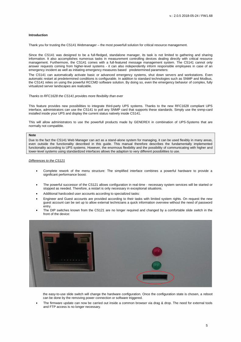
The DIP switches known from the CS121 are no longer required and changed by a comfortable slide switch in the front of the device:
the easy-to-use slide switch will change the hardware configuration. Once the configuration state is chosen, a reboot can be done by the removing power connection or software triggered.
The firmware update can now be carried out inside a common browser via drag & drop. The need for external tools and FTP access is no longer necessary.

v.: 2.0.5 2018-05-24 / FW1.68
6
In case of problems with the firmware, updates or reboots can also be carried out without a complete login. To do this, use a commen webbrowser and enter the IP of the device followed by /update. After a successful admin authentication, the firmware can now be updated and optionally resetted to factory settings.
By default, auto logout is now enabled. On inactivity, the user is logged out of the system after 15 minutes.
The power consumption of the CS141 has been reduced by a factor of 10 with a power increase and is well below the predecessor model.
Model overview
Device Function Remarks
CS141L SNMP adapter external adapter
CS141SC SNMP adapter Slot Adapter for UPS with slot
CS141LM SNMP adapter External adapter with MODBUS output (RS485)
CS141SCM SNMP adapter Slot adapter with MODBUS output (RS485)
CS141BL SNMP adapter External adapter BUDGET-Modell (No COM2- and AUX-port)
CS141BSC SNMP adapter Slot adapter BUDGET-Modell (No COM2- und AUX-port)
CS141R_2 SNMP adapter Slot adapter for PILLER/CTA/RIELLO/AROS UPS Italy
CS141MINI SNMP adapter Slot adapter for UPS models with MINI Slot
Additional devices based on CS141:
Device Function Remarks
BACSKIT_B4 Battery management External adapter
BACSKIT_BSC4 Battery management Slot adapter
Device Features Supported UPS devices
CS141L Additional Mini DIN 8 COM Port for RS232. AUX Port for Digital Input/Output. Remote RAS Management optional.
Over 1400 UPS modells from over 80 different manufacturers are supported
CS141SC Additional Mini DIN 8 COM Port for RS232. AUX Port for Digital Inpuit/ Output. Remote RAS Management optional.
All devices with basic slot SC
CS141LM Additional Mini device. AUX Port for Digital Input/ Output.. Remote RAS Management optional.
Over 1400 UPS modells from over 80 different manufacturers are supported
CS141SCM Additional RS485. AUX Port for Digital Input/ Output. Remote RAS Management optional.
All devices with basic Slot SC
CS141BL Slot Budget variant of the CS141. UPS Manage-ment via LAN. No AUX Port for floating contacts. No COM2 Port for Pipe-through, sensors, etc.
Over 1400 UPS modells from over 80 different manufacturers are supported
CS141BSC Slot Budget variant of the CS141. UPS Manage-ment via LAN. No AUX Port for floating contacts. No COM2 Port for Pipe-through, sensors, etc.
All devices with basic Slot SC
CS141R_2 Additional Mini DIN 8 COM Port for RS232.. Riello and Aros UPS with Netman Slot
CS141MINI Additional Mini DIN 8 COM Port for RS232. UPS devices with MINI Slot (Soltec, Voltronic, etc)
All CS141s can manage UPS systems providing a native serial protocol. Furthermore, the CS141 can be easily integrated into existing SNMP systems.
All models of the CS141 family provide an own unique web server with configurable event management for automating job executions based on the status of the UPS.
All CS141s can manage UPS systems providing a native serial protocol. Furthermore, the CS141 can be easily integrated into existing SNMP systems.
All models of the CS141 family provide an own unique web server with configurable event management for automating job executions based on the status of the UPS, including:
- email notification - Full RCCMD funcinality - shutdown commands, - logfile entries, shutdown of the UPS, - graphical log files, - shutdown and wake-up -commands
In addition, the CS141 can also be individually configured using a scheduler to trigger job executions for many events, eg: - battery testing - calibration - UPS or system shutdown / restore. The CS141 provides a wide range of network management features to inform and alert required persons before a critical incident occurs.
v.: 2.0.5 2018-05-24 / FW1.68
7
The CS141 cann even monitorr other SNMP devices and thanks to its build in RCCMD solution, combine them to an intelligent power resource management. Each adapter has 2 years warranty as well as free updates for 3 years. All devices are manufactured in Germany
Content on delivery
The scope of delivery of a CS141 includes a supplementary Software Compact Disk and additional hardware.
Note: The budget edition does not support all features described in this manual.
Product Included on delivery
External power supply
User’s manual on CD
Mini-DIN-8 Connector (MODBUS)
RS-485
Via COM2
Rescue Jumper
CS141L X X X X
CS141SC X X X
CS141LM X X X X
CS141SCM X X X
CS141BL X X X
CS141BSC X X
CS141R_2 X X
CS141MINI X X
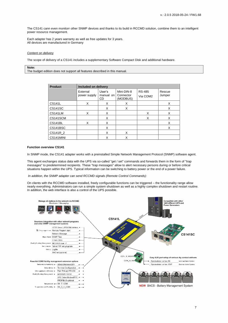
Function overview CS141 In SNMP mode, the CS141 adapter works with a preinstalled Simple Network Management Protocol (SNMP) software agent. This agent exchanges status data with the UPS via so-called "get / set" commands and forwards them in the form of "trap
messages" to predetermined recipients. These "trap messages" allow to alert necessary persons during or before critical
situations happen within the UPS. Typical information can be switching to battery power or the end of a power failure.
In addition, the SNMP adapter can send RCCMD signals (Remote Control Commands): On clients with the RCCMD software installed, freely configurable functions can be triggered – the functionality range allow nearly everything. Administrators can run a simple system shutdown as well as a highly complex shutdown and restart routine. In addition, the web interface is also a control of the UPS possible.

v.: 2.0.5 2018-05-24 / FW1.68
8
In SNMP mode, the CS141 adapter works with a preinstalled Simple Network Management Protocol (SNMP) software agent. This agent exchanges status data with the UPS via so-called "get / set" commands and forwards them in the form of "trap messages" to predetermined recipients.These "trap messages" allow to alert neccessary persons during or before critical situations happen within the UPS. Typical information can be switching to battery power or the end of a power failure. In addition, the SNMP adapter can send RCCMD signals (Remote Control Commands): On clients with the RCCMD software installed, freely configurable functions can be triggered up to complex shutdown and start routines In addition, administrators can monitor and control their UPS possible by using the build in web interface to ensure a all-in-one solution for nearly the entire UPS system:
SNMP Trap functionality The basic task of the adapter is to communicate alarm states of the UPS to an according monitoring station (traps) or to provide UPS data if monitoring stations poll. With this function, e.g. the power supply and battery status of a UPS are monitored by an SNMP management station. Additionally, the CS141 provides functions for simulating and testing trap messages during configuration procedure.
Remote Control:
Due to the fact the CS141 is capable to configure it is possible to trigger different remote-controlled actions. Administrators can perform battery tests, bypass the UPS batteries or configure UPS behavior
Note:
Depending on the UPS you are using, provided functions may differ.
Compatibility according to third party network management systems
The SNMP adapter is compatible with all common network management systems. All SNMP systems providing the compilation of a MIB - or already contain the Management Information Base (MIB) / Request for Comment 1628 (RFC) for UPS systems - can be operated with CS141. Full RCCMD support: Due to the fact the CS141 is a full manager and not just an SNMP-Card to collect and provide data, the entire network shutdown routine can be configured to react as fast as possible: Thanks to integrated RCCMD support, the CS141 offers a flexible and fast way to operate even the most complex shutdown solutions. By the usage of standardized network technologies and protocols, the patented RCCMD server transfers control commands that are executed by the clients in real time. RS-232 / pipe-through: In some cases, different networks without any connections have to be configured to use the same UPS. With the new pipe-through capability administrators can connect two CS141 and let the communication of the UPS work with both devices: By doing so, two different CS141 can communicate to according networks without additional hardware.
Provided real-time logfiles:
The CS141 provides a proven compilation of logfiles to reconstruct a complete timeline in case of critical incidents. This logfile is accessible via UNMS, UPSMAN, WebGUI and FTP or can be send via mail to configured mail-accounts.
Advanced mailing capabilities
Each model of the CS141 family provides the capability to connect to any mail server using standardized encryption technologies.
Unique web server included: The unique build-in Web server of the CS141 displays all information about the device itself, connected sensor and external hardware. The software module UPSView inside the CS141 can also be used to display a graphical representation of these data. To Access the web interface administrators and technicians may just use common browsers (Edge, Firefox, Chrome, Safari etc.).
v.: 2.0.5 2018-05-24 / FW1.68
9
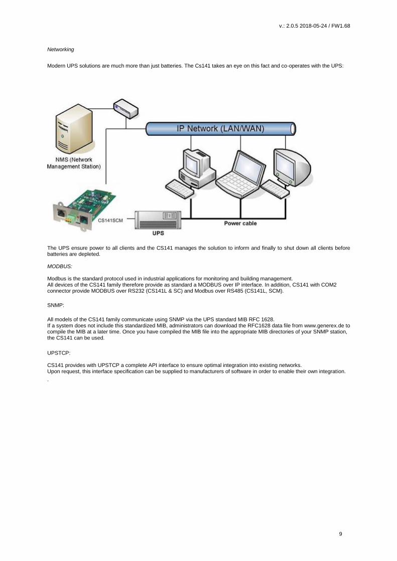
Networking
Modern UPS solutions are much more than just batteries. The Cs141 takes an eye on this fact and co-operates with the UPS:
The UPS ensure power to all clients and the CS141 manages the solution to inform and finally to shut down all clients before batteries are depleted. MODBUS: Modbus is the standard protocol used in industrial applications for monitoring and building management. All devices of the CS141 family therefore provide as standard a MODBUS over IP interface. In addition, CS141 with COM2 connector provide MODBUS over RS232 (CS141L & SC) and Modbus over RS485 (CS141L, SCM).
SNMP:
All models of the CS141 family communicate using SNMP via the UPS standard MIB RFC 1628. If a system does not include this standardized MIB, administrators can download the RFC1628 data file from www.generex.de to compile the MIB at a later time. Once you have compiled the MIB file into the appropriate MIB directories of your SNMP station, the CS141 can be used.
UPSTCP: CS141 provides with UPSTCP a complete API interface to ensure optimal integration into existing networks. Upon request, this interface specification can be supplied to manufacturers of software in order to enable their own integration.
.

v.: 2.0.5 2018-05-24 / FW1.68
10
Hardware layout
1. Slide-Switch for network configuration
2. Network Interface
3. COM2 MINIDIN Connector for RS232
4. COM2 Phoenix Connector for RS485
5. Green and Red Status LED
6. AUX Interface
7. PoE Header
8. Debug Adapter
9. Rescue Jumper: Open = Normal Boot, Close = Rescue Boot
10. NAND Flash
11. CPU
12. RAM
13. USB Interface
14. COM1
15. Slot Interface
16. Power Supply
17. DIP Switch
18. Fuse

v.: 2.0.5 2018-05-24 / FW1.68
11
Interface Description
External D-SUB 9-polig male
Pin1: DCD Pin6: DSR
Pin2: RxD Pin7: RTS
Pin3 TxD Pin8: CTS
Pin4 DTR Pin9: RI
Pin5 GND
Slot version: Circuit board connection
Pin Signal name Level Function
1 GND Power Ground
2 8 – 34V DC Power Input
3 COM1 TXD V24 COM1 Transmit Data
4 COM1 RXD V24 COM1 Receive Data
5 SW_GPIO_1 1) 2) 3,3V TTL CS141DMINI: Functionality of DIP-Switch 1
6 SW_GPIO_2 1) 2) 3,3V TTL CS141DMINI: Functionality of DIP-Switch 2
7 POW# Input 1) 3,3V TTL Enable power supply (active low)
8 Bridged with Pin 10
9 GND Signal Ground
10 Bridged with Pin 8
11 COM1 DTR 1) V24 COM1 Data Transmit Ready
12 COM1 RI 1) V24 COM1 Ring Indicator
13 COM3 RXD 1) 2) 5V TTL COM3 Receive Data
14 COM3 TXD 1) 2) 5V TTL COM3 Transmit Data
15 COM2 TXD 1) 2) 3,3V TTL COM2 Transmit Data
16 COM2 RXD 1) 2) 3,3V TTL COM2 Receive Data
17-26 - n.c.
1) Connectable with solder bridge (MINI: resistor bridge)
2) Input with Pull-Up
v.: 2.0.5 2018-05-24 / FW1.68
12
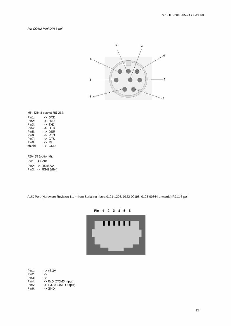
Pin COM2 Mini-DIN 8 pol
Mini DIN 8 socket RS-232:
Pin1: -> DCD Pin2: -> RxD Pin3: -> TxD Pin4: -> DTR Pin5: -> DSR Pin6: -> RTS Pin7: -> CTS Pin8: -> RI shield -> GND
RS-485 (optional):
Pin1 GND
Pin2: -> RS485/A Pin3: -> RS485/B(-)
AUX-Port (Hardware Revision 1.1 = from Serial numbers 0121-1203, 0122-00198, 0123-00564 onwards) RJ11 6-pol
Pin1: -> +3,3V Pin2: -> Pin3: -> Pin4: -> RxD (COM3 Input) Pin5: -> TxD (COM3 Output) Pin6: -> GND

v.: 2.0.5 2018-05-24 / FW1.68
13
Network integration of the CS141
All models of the CS141 family are configured exclusively through the specially designed web interface.
In order to facilitate the initial configuration or a quick on-site intervention, the CS141 family Web Manager is preset to the hard-coded IP address 10.10.10.10:
:
You will recognize this presetting that the slide switch is in the middle position on the front side. Due to its more compact design, the CS141 MINI brakes the standard and uses on-board dip switches instead of a sliding switch. You will recognize this presetting that the slide switch is in the middle position on the front side. Due to its more compact design, the CS141 MINI brakes the standard and uses on-board dip switches instead of a sliding switch. The center position or alternatively both dip-switches set to off position activates the configuration mode: In this mode, some functions such as IP address data are configurable, but available only as soon as CS141 is switched to regular operating mode.
The following table lists regular operating modes:
Sliding switch center position / DIP 1 + 2 OFF:
Enables configuration mode. After reboot the hard-coded IP address 10.10.10.10
is active.
Sliding switch to the right / Dip 1 OFF + 2 DIP 2 ON: Automatic IP addressing: DHCP is activated and an IP address is set automatically. Check the MAC address of your CS141 to identify the IP address in the DHCP server table.
. Sliding switch to he left / DIP 1 ON + DIP 2 OFF:
Use of the IP address values manually configured. If DHCP is used, the IP
address needs to be blocked for single usage.
CS141 Mini special feature:
Both Dip-Switches ON:
Enables the rescue-mode for advanced system maintenance operation.
v.: 2.0.5 2018-05-24 / FW1.68
14
Initial configuration 10.10.10.10
Preparation at the CS41
Prior to commissioning, ensure the slide switch on the front is set to center position. In case of CS141Mini, both Dip switches of the CS141 MINI has to be set in OFF position. After start up, the CS141 can be runs in configuration mode, available at IP address 10.10.10.10.
Note: Changing the mode via the hardware switches requires a reboot of the CS141. You can perform the restart in two ways: By removing the power supply (hardware reset) Using the Restart feature to be found inside the Tools menu (Software Reset) This operation does not apply the UPS the CS141 is connected to - the functionality will be kept up independently to the CS141.
Preparing the Workstation
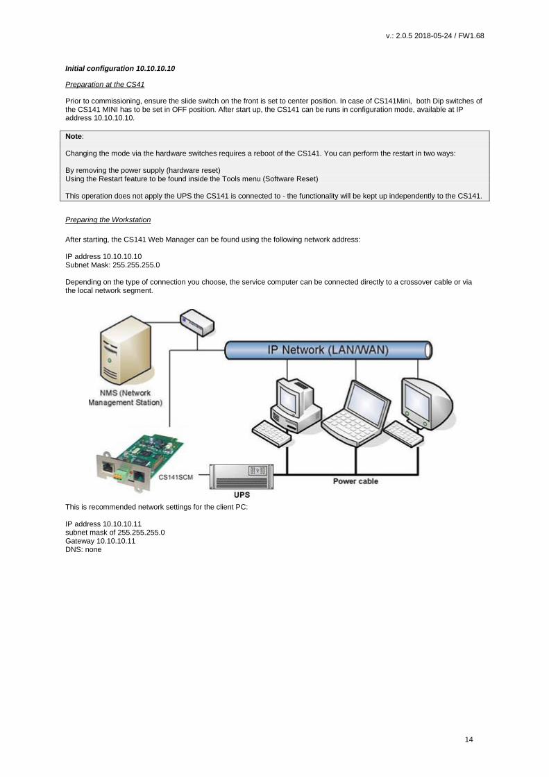
After starting, the CS141 Web Manager can be found using the following network address: IP address 10.10.10.10 Subnet Mask: 255.255.255.0 Depending on the type of connection you choose, the service computer can be connected directly to a crossover cable or via the local network segment.
This is recommended network settings for the client PC: IP address 10.10.10.11 subnet mask of 255.255.255.0 Gateway 10.10.10.11 DNS: none
v.: 2.0.5 2018-05-24 / FW1.68
15
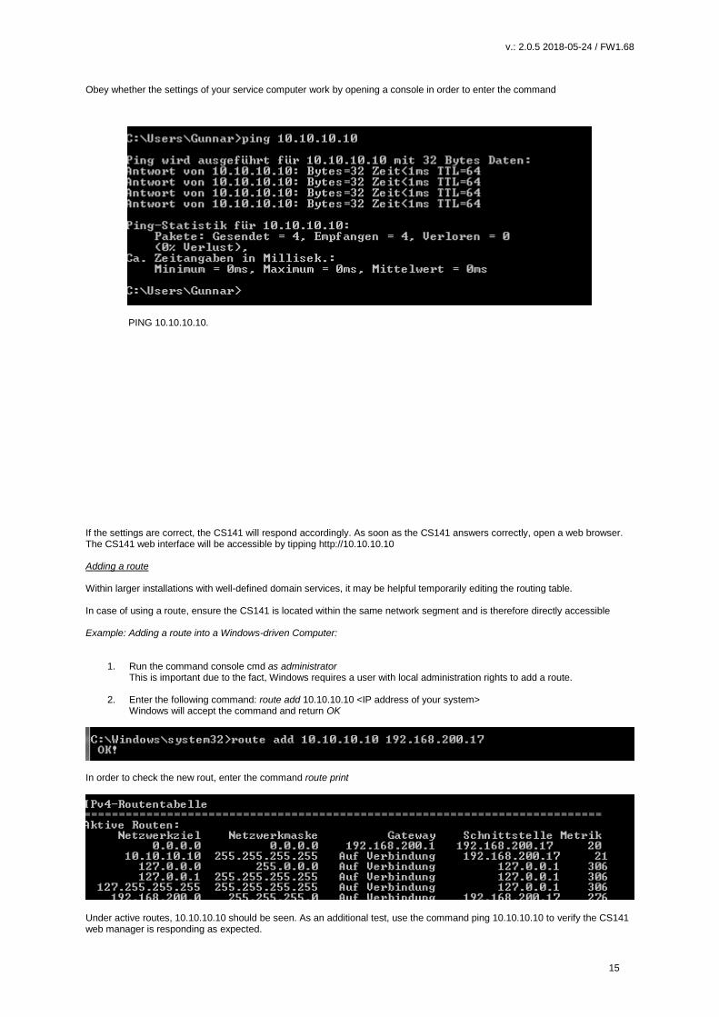
Obey whether the settings of your service computer work by opening a console in order to enter the command
PING 10.10.10.10.
If the settings are correct, the CS141 will respond accordingly. As soon as the CS141 answers correctly, open a web browser. The CS141 web interface will be accessible by tipping http://10.10.10.10 Adding a route Within larger installations with well-defined domain services, it may be helpful temporarily editing the routing table. In case of using a route, ensure the CS141 is located within the same network segment and is therefore directly accessible Example: Adding a route into a Windows-driven Computer:
1. Run the command console cmd as administrator This is important due to the fact, Windows requires a user with local administration rights to add a route.
2. Enter the following command: route add 10.10.10.10 <IP address of your system> Windows will accept the command and return OK
In order to check the new rout, enter the command route print
Under active routes, 10.10.10.10 should be seen. As an additional test, use the command ping 10.10.10.10 to verify the CS141 web manager is responding as expected.
v.: 2.0.5 2018-05-24 / FW1.68
16
Note: In configuration mode, only one CS141 with the default IP address of 10.10.10.10 can be operated. If you connect several devices at the same time this way, a network conflict is unavoidable.
Using the DHCP Option The DHCP mode Since the models of the CS141 family can fulfill many functions due to their flexibility, it is a very realistic scenario that you need to commission several devices at the same time within an installation procedure - Unfortunately there is no fixed IP address that can be assigned for the moment. To avoid a network conflict, activate the DHCP mode for automatic IP address assigning: Slide the slide switch to the right, i.e. to the outer edge of the CS141. For the CS141 Mini, set dip switch 1 to OFF and move dip switch 2 to ON. Next reboot, the web manager will boot in DHCP mode according to the hardware configuration and obtain an IP address from your network.

v.: 2.0.5 2018-05-24 / FW1.68
17
Required information for finding CS141 in DHCP-Mode To identify the devices, please note the MAC address including location data before proceeding hardware installation. The MAC address can be found on any CS141 web manager as a unique sticker:
Ensure a suitable DHCP server is available for this operating mode, otherwise the will not be able to get valid IP address data automatically. Netfinder: Search for IP-addresses used with CS141 devices The Netfinder is a software tool that can display all CS121 and CS141 devices that can be reached inside a specific network segment. It is available at the local support CD and at www.generex.de. To perform a quick search for valid IP addresses, use the tool Netfinder.
The default search generally refers to the network segment the service computer resides. To scan other networks and subnets for CS121 or CS141 installations, it is necessary to specify the appropriate IP address ranges.
v.: 2.0.5 2018-05-24 / FW1.68
18
The GENEREX Netfinder software provides a detailed overview of all devices in the network and allows quick and easy access to the web console of the respective manager.
Note: In DHCP mode, IP addresses may change sporadically depending on the network configuration. Therefore, several webmanagers monitored by a parent system such as UNMS II should receive a fixed IP address. In any other case, technicians can easy detect and access installed devices by using Netfinder.
Configuring the CS141 device Differences between configuration mode, rescue mode and operation mode Each model of the CS141 family will be configured exclusively by an intuitive web interface. Independently to this common ground, the web managers offer four valid operating states, which fundamentally differ from each other.
1. The configuration mode The configuration mode is the default preset on delivery: The slide switch is in center position and the dip switches of the CS141Mini are both set to OFF. The web manager can be reached via hardware-coded preset IP address 10.10.10.10 and allows all system-relevant settings Since the CS141 generally uses the preset IP address in configuration mode, this mode allows importing backup data and to be adjusted after restart without harming the network. Operating mode Depending on the setting, the sliding switch will be set to left or right position. In case of CS141Mini, Dip switch 1 or 2 is switched on The CS141 can be run in two different operation modes: In manual mode, enter the IP address information. Please note that incorrect settings may cause address conflicts on the network or the settings made may not work. The data required for manual mode can be obtained from local system administrators.
Note: In manual mode, the data is entered by technicians and thus permanently assigned. The CS141 will use this data to make itself known in the network. assigning an address twice will cause a network conflict. In this case, switching back to configuration mode at any time is possible to reach the Web Manager at the default IP address 10.10.10.10.
In DHCP mode, the CS141 automatically inherits settings assigned by a server and uses them for the IP address settings. The web server takes over the administration of the IP address data. After the startup process, the web manager can be found using the tool Netfinder.
Tipp: As a rule, DHCP-assigned IP addresses via automatic mode are reserved for specific time. DHCP clients therefore ask after 50% of this time window whether the IP address is still valid or will be assigned to another client. How statically the DHCP server allocates IP addresses is a decision the system administrators make. Due to this fact another IP address can be re-assigned after booting or a CS141 seems to be lost during regular operation.
When selecting the operating mode, the function of the CS141 within the network should be considered: If the Web Manager runs as an active element within shutdown solutions or in conjunction with higher-level monitoring structures, a manually assigned IP address makes sense, since an authenticated and fixed IP address must be configured. As another advantage the CS141 starts faster with preconfigured IP addresses if the DHCP server is not available.
2. The rescue mode In this mode, an additional jumper is set and the slide switch center position The CS141Minis Setup is both Dip switches ON. The webmanager can access two ROMs for booting. Therefore, this failsafe design is able to contain the current firmware as well as the last state before the firmware update including the configuration file. When the web manager is set to rescue mode, the logic starts from the last known state and is initially fully operational again but indicates in the general system information that the web manager is in rescue mode. The rescue mode represents a manually chosen emergency operation state and is intended to repeat a faulty flash process.

v.: 2.0.5 2018-05-24 / FW1.68
19
Before you start Installation examples The CS141 was designed to provide a maximum of flexibility and freedom during the installation - as a result the CS141 match the tasks of modern UPS systems as well as expectations coming with it. Case one:
The central part of the UPS is to ensure emergency power until the server shut down securely during main power loss. The complete shutdown routine is controlled by the CS141, as this is a full-fledged manager that can act independently. As an alternative to the CS141, the shutdown routine can also be initiated via the UPSMan software. Further servers need only one more RCCMD license. Two separate networks It becomes more difficult as soon as emergency power coming one UPS has to ensure the shutdown of two servers inside separate networks without linking possibilities:
In this case, the UPS becomes a central role inside the networks emergency power security. Since the VLANs represent physically separated own network segments, only one server can be secured by the CS141. The UPSMan software will secure the second server: Once Installed directly on the server, it communicates with the UPS via the COM port of the server and offers the same functionality as the CS141 including a full support of RCCMD. Therefore VLAN 2 represents a "software only" solution that does not require a CS141 as additional hardware.
v.: 2.0.5 2018-05-24 / FW1.68
20
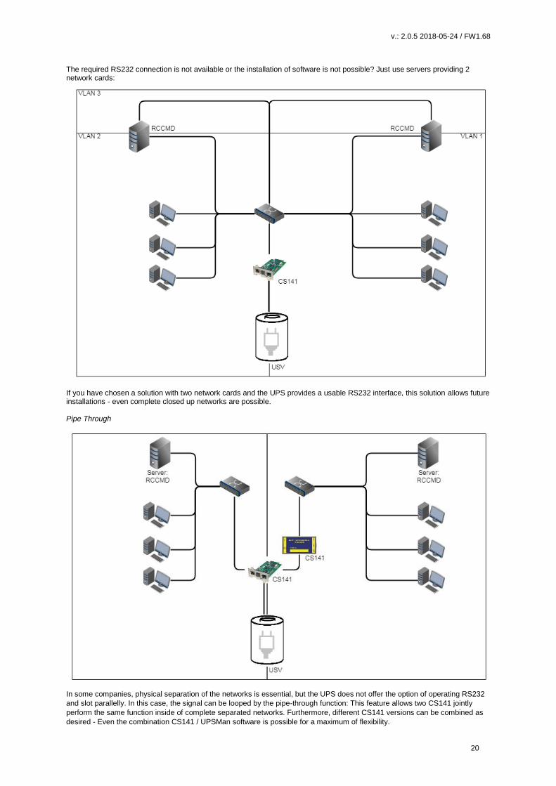
The required RS232 connection is not available or the installation of software is not possible? Just use servers providing 2 network cards:
If you have chosen a solution with two network cards and the UPS provides a usable RS232 interface, this solution allows future installations - even complete closed up networks are possible. Pipe Through
In some companies, physical separation of the networks is essential, but the UPS does not offer the option of operating RS232
and slot parallelly. In this case, the signal can be looped by the pipe-through function: This feature allows two CS141 jointly
perform the same function inside of complete separated networks. Furthermore, different CS141 versions can be combined as
desired - Even the combination CS141 / UPSMan software is possible for a maximum of flexibility.
v.: 2.0.5 2018-05-24 / FW1.68
21
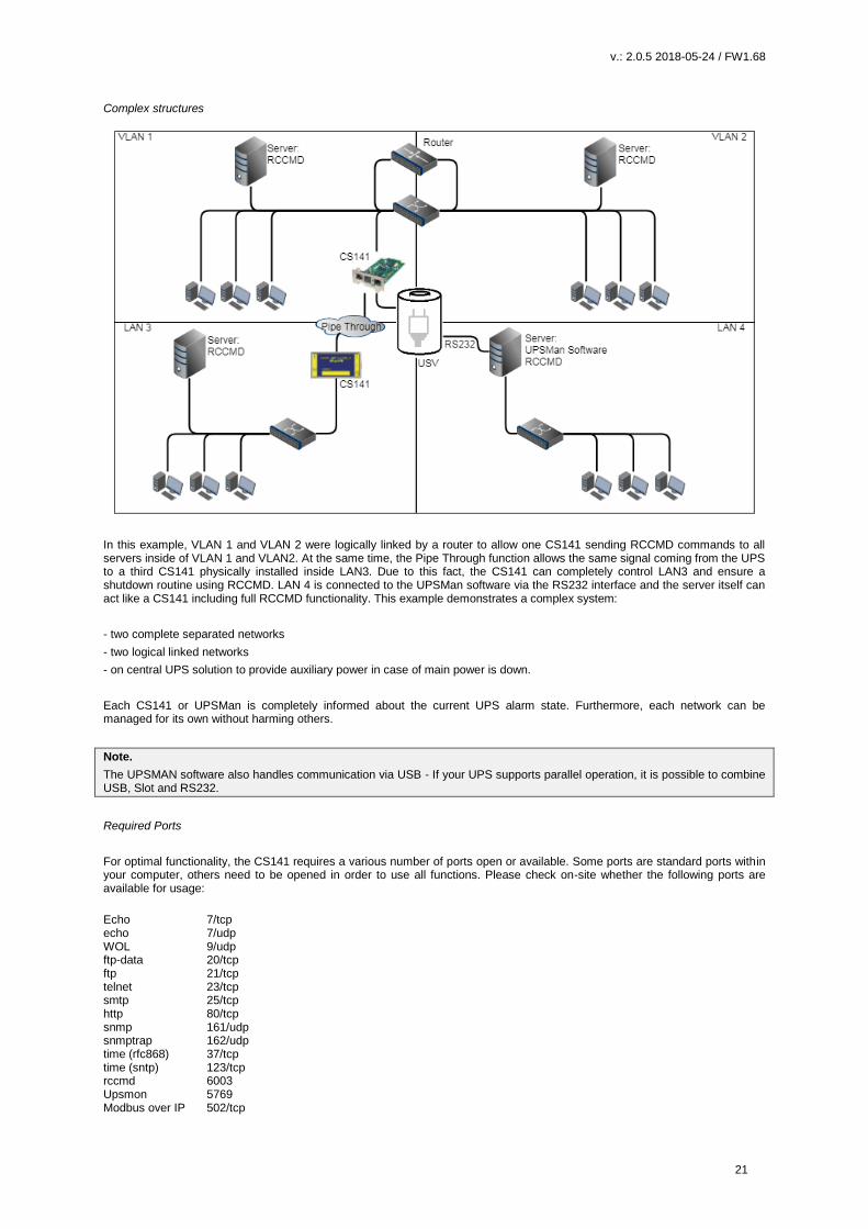
Complex structures
In this example, VLAN 1 and VLAN 2 were logically linked by a router to allow one CS141 sending RCCMD commands to all servers inside of VLAN 1 and VLAN2. At the same time, the Pipe Through function allows the same signal coming from the UPS to a third CS141 physically installed inside LAN3. Due to this fact, the CS141 can completely control LAN3 and ensure a shutdown routine using RCCMD. LAN 4 is connected to the UPSMan software via the RS232 interface and the server itself can act like a CS141 including full RCCMD functionality. This example demonstrates a complex system:
- two complete separated networks
- two logical linked networks
- on central UPS solution to provide auxiliary power in case of main power is down.
Each CS141 or UPSMan is completely informed about the current UPS alarm state. Furthermore, each network can be managed for its own without harming others.
Note.
The UPSMAN software also handles communication via USB - If your UPS supports parallel operation, it is possible to combine USB, Slot and RS232.
Required Ports
For optimal functionality, the CS141 requires a various number of ports open or available. Some ports are standard ports within your computer, others need to be opened in order to use all functions. Please check on-site whether the following ports are available for usage:
Echo 7/tcp echo 7/udp WOL 9/udp ftp-data 20/tcp ftp 21/tcp telnet 23/tcp smtp 25/tcp http 80/tcp snmp 161/udp snmptrap 162/udp time (rfc868) 37/tcp time (sntp) 123/tcp rccmd 6003 Upsmon 5769 Modbus over IP 502/tcp

v.: 2.0.5 2018-05-24 / FW1.68
22
Tipp: This user guide covers all the menus that you can encounter when configuring a CS141. Basically it is written for firmware version 1.62 and subsequent versions. If you can not find a menu, there are several reasons: The CS141 you are using does not offer this feature The firmware version you are using is older so the feature this manual describes is not available The configuration menu is present, but has been delayed by the ongoing development process
Basic settings After you enter the IP address, the CS141 responds with its web interface and prompts for a password There are three users with different system rights to choose from. The users are predefined, the passwords can be freely defined: User: admin Password: cs141-snmp ... System administrator, complete menu tree accessible User: engineer Password: engineer ... Technician, administrative restricted system access User: guest Password: guest … guest account, only status indicators visible To start initial configuration, log in with user admin and default password cs141-snmp
Note: Modern web browsers are designed to display websites as fast as possible. Among other things, special techniques are used to pre-load images, pages and query masks are loaded into a buffer for a faster review. In some cases, this web browser behavior may result in screen errors. If these phenomena occur, update the browser by pressing CTRL + F5 or clear the cache of the web browser and deactivate additionally installed tools and addons, which could obstruct the presentation.

v.: 2.0.5 2018-05-24 / FW1.68
23
The Setup Wizard
Setup Wizard
When you use the CS141 for the first time, the welcome screen will automatically start with the wizard. Please note that you cannot switch through the masks directly, you need to follow by pressing next.
The Setup Wizard helps to set up a basic configuration: General Provides basic information about the location to be installed, system language, responsibilities and temperature scale. Network Enter the network configuration - The necessary data can be obtained from the local administrator. Date & Time Provide basic information about the date, time, and time server UPS Setup Enter information about the UPS the CS141 shall be connected to Review Check data before you finish the configuration process before finishing.
Note:
The Setup Wizard simply summarizes basic settings and provides a quick and convenient solution that can be used to make or
change basic settings. If you want to perform the configuration completely manually, click here Cancel - You can always restart
the Setup Wizard in the configuration menu.
But be careful: Some entries such as UPS configuration have dependencies to advanced configuration entries the Wizard does
not include.

v.: 2.0.5 2018-05-24 / FW1.68
24
Basic settings in configuration mode
Opens System configuration menu: Basic system information
Setup Wizard
Location settings, contact details, required services
IP-address settings and hostname Time services, date system time
Most settings can be done as long as the CS141 is in configuration mode. Depending on your network settings there could be a problem when performing tests and forwarding functions - they are often not possible on hardware preset 10.10.10.10. Due to this fact it is a good choice to configure all basic settings inside configuration mode and switch to normal mode before starting advanced UPS configuration. To configure system’s network configuration, open Network:
Under Configure, enter the IP address data the system shall use. Active shows the current IP address settings used by the system. It is possible to change the following settings
Hostname: location data, system name, serial number. local IP address
subnet mask
gateway service of the network
DNS-Server
On first startup, the CS141 will get hard-coded information. The required IP address information to enter the operational mode correctly can be obtained by contacting the responsible network administrator. Press Apply to save your settings.
Note: At this point, the web browser redirects you to the new IP address. Since the CS141 is still in configuration mode, you will receive an error message from your web browser. In this case, ensure to work with the IP 10.10.10.10 and press CTRL F5 to refresh the web browser.
For a first configuration, the Network menu is the only setting you currently need to make in Configuration mode. It is possible to carry out all other settings in regular operating mode. Special feature Initial configuration in DHCP mode During starting up the CS141 in DHCP mode, an according server assigns an IP address to this device. This IP address can be found comfortable by using the free tool Netfinder. Therefore, it is easy to identify the device by the MAC address shown by
Netfinder and the address label glued on the CS141 device:
v.: 2.0.5 2018-05-24 / FW1.68
25
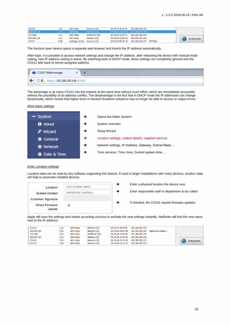
The function open device opens a separate web browser and inserts the IP address automatically. After login, it is possible to access network settings and change the IP address. after rebooting the device with manual mode setting, new IP address setting is active. By switching back to DHCP mode, these settings are completely ignored and the CS141 falls back to server-assigned address.
The advantage is as many CS141 into the network at the same time without much effort, which are immediately accessible without the possibility of an address conflict. The disadvantage is the fact that in DHCP mode the IP addresses can change dynamically, which means that higher-level or docked shutdown solutions may no longer be able to access or output errors. More basic settings
Opens the folder System: System overview Setup Wizard Location settings, contact details, required services Network settings, IP-Address, Gateway, Subnet Mask… Time services, Time zone, Current system time…
Enter Location settings Location data can be read by any software supporting this feature. If used in larger installations with many devices, location data will help to associate installed devices.
Enter a physical location the device runs Enter responsible staff or department to be called
If checked, the CS141 reports firmware updates
Apply will save the settings and restart according services to activate the new settings instantly. Netfinder will find the new name next to the IP address:
v.: 2.0.5 2018-05-24 / FW1.68
26
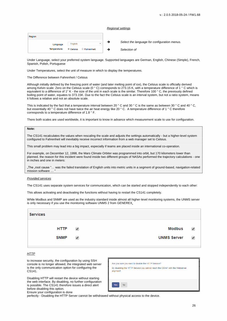
Regional settings
Select the language for configuration menus.
Selection of
Under Language, select your preferred system language. Supported languages are German, English, Chinese (Simple), French,
Spanish, Polish, Portuguese
Under Temperatures, select the unit of measure in which to display the temperatures.
The Difference between Fahrenheit / Celsius Although initially defined by the freezing point of water (and later melting point of ice), the Celsius scale is officially derived among Kelvin scale: Zero on the Celsius scale (0 ° C) corresponds to 273.15 K, with a temperature difference of 1 ° C which is equivalent to a difference of 1° K - the size of the unit in each scale is the similar. Therefore 100 ° C, the previously defined boiling point of water, equates to 373.15K. Due to the fact the Celsius scale is an interval system, but not a ratio system, means it follows a relative and not an absolute scale. This is indicated by the fact that a temperature interval between 20 ° C and 30 ° C is the same as between 30 ° C and 40 ° C, but essentially 40 ° C does not have twice the air heat energy like 20 ° C. A temperature difference of 1 ° C therefore corresponds to a temperature difference of 1.8 ° F. There both scales are used worldwide, it is important to know in advance which measurement scale to use for configuration.
Note: The CS141 recalculates the values when rescaling the scale and adjusts the settings automatically - but a higher-level system configured to Fahrenheit will inevitably receive incorrect information from a web manager set to Celsius. This small problem may lead into a big impact, especially if teams are placed inside an international co-operation. For example, on December 12, 1998, the Mars Climate Orbiter was programmed into orbit, but 170 kilometers lower than planned. the reason for this incident were found inside two different groups of NASAs performed the trajectory calculations - one in inches and one in meters: „The „root cause “… was the failed translation of English units into metric units in a segment of ground-based, navigation-related mission software … “
Provided services The CS141 uses separate system services for communication, which can be started and stopped independently to each other: This allows activating and deactivating the functions without having to restart the CS141 completely. While Modbus and SNMP are used as the industry standard inside almost all higher-level monitoring systems, the UNMS server is only necessary if you use the monitoring software UNMS 2 from GENEREX.
HTTP to increase security, the configuration by using SSH console is no longer allowed, the integrated web server is the only communication option for configuring the CS141. Disabling HTTP will restart the device without starting the web interface. By disabling, no further configuration is possible. The CS141 therefore issues a direct alert before disabling this option. Ensure your configuration is done perfectly - Disabling the HTTP Server cannot be withdrawed without physical access to the device.
v.: 2.0.5 2018-05-24 / FW1.68
27
Tipp: The rescue system on the CS141 has not only saved the last firmware, but also the last configuration before your update. If you intend to deactivate the http functionality, it is recommended to perform a firmware update before this last configuration step: By doing it, you will be able to access the system by its build-in rescue mode.
Why it is possible to deactivate this server In some cases, it is necessary to ensure a minimum of possible interactions. The CS141 takes care even in this seldom cases: Depending on its configuration only additional sftp-access is possible in order to download data logs. Therefore, the admin password can be known without consequences of network security. SNMP The Simple Network Management Protocol (SNMP) is a network protocol developed by the IETF to monitor and control network elements from a central station. The protocol controls the communication between the monitored devices and the monitoring station. Thereby SNMP describes the structure of the data packets that can be sent as well as the entire communication process. It was designed to ensure any network-capable device can be implemented into monitoring systems. Possible tasks of network management using SNMP include: - monitoring of network components, Remote control and remote configuration of network components - Error detection and error notification. With its simplicity, modularity and versatility, SNMP has become the standard supported by most management programs as well as endpoints. If you want to use SNMP in your network, leave the check mark active for this function. Modbus Fieldbuses are bus systems that connect field devices like sensors or actuators inside a complex device to allow communication to an according full-automated managing system. If several communication partners send their information over the same line, it is necessary to ensure communication about fixed rules:
- who (identifier) - what (measure, command) and - when (initiative)
To ensure this communication, there are standardized protocols to be used. Historical facts: The Modbus protocol was launched in 1979 by Gould-Modicon for communicating with its programmable logic controllers and has become an unofficial standard for industrial usage due to its open protocol standard. Since 1999, fieldbuses have been standardized worldwide in the IEC 61158 standard (Digital data communication for measurement and control - Fieldbus for use in industrial control systems). The second generation of fieldbus technology is based on real-time Ethernet.
Tipp: For further information, please refer to the manual for Modbus, which you can download from the download area of our website at www.generex.de.
UNMS Server The UNMS server was specially developed to communicate with the universal network management software from GENEREX. The powerful successor UNMS 2 communicates via UPSTCP on port 5769. The UPS server service enables or disables availability through this port. If you are using a UNMS / UNMS 2 installation, leave this feature enabled.
v.: 2.0.5 2018-05-24 / FW1.68
28
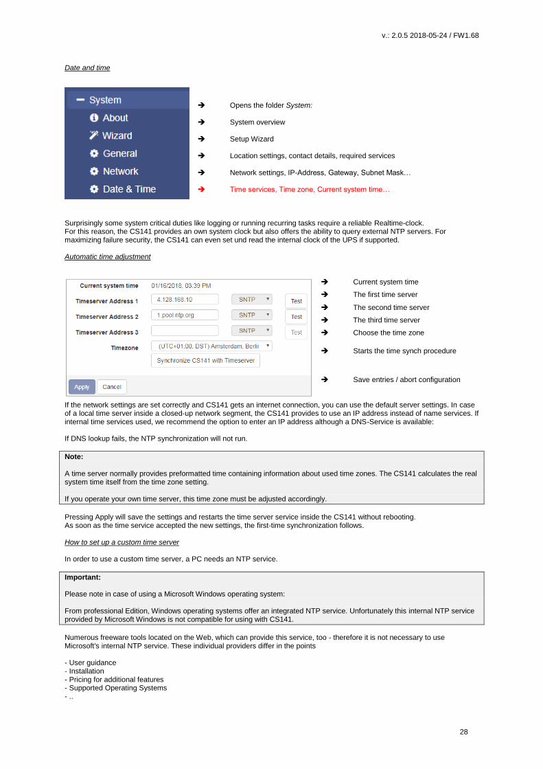
Date and time
Opens the folder System: System overview Setup Wizard Location settings, contact details, required services Network settings, IP-Address, Gateway, Subnet Mask… Time services, Time zone, Current system time…
Surprisingly some system critical duties like logging or running recurring tasks require a reliable Realtime-clock. For this reason, the CS141 provides an own system clock but also offers the ability to query external NTP servers. For maximizing failure security, the CS141 can even set und read the internal clock of the UPS if supported. Automatic time adjustment
Current system time
The first time server
The second time server
The third time server
Choose the time zone
Starts the time synch procedure
Save entries / abort configuration
If the network settings are set correctly and CS141 gets an internet connection, you can use the default server settings. In case of a local time server inside a closed-up network segment, the CS141 provides to use an IP address instead of name services. If internal time services used, we recommend the option to enter an IP address although a DNS-Service is available: If DNS lookup fails, the NTP synchronization will not run.
Note: A time server normally provides preformatted time containing information about used time zones. The CS141 calculates the real system time itself from the time zone setting. If you operate your own time server, this time zone must be adjusted accordingly.
Pressing Apply will save the settings and restarts the time server service inside the CS141 without rebooting. As soon as the time service accepted the new settings, the first-time synchronization follows. How to set up a custom time server In order to use a custom time server, a PC needs an NTP service.
Important: Please note in case of using a Microsoft Windows operating system: From professional Edition, Windows operating systems offer an integrated NTP service. Unfortunately this internal NTP service provided by Microsoft Windows is not compatible for using with CS141.
Numerous freeware tools located on the Web, which can provide this service, too - therefore it is not necessary to use Microsoft's internal NTP service. These individual providers differ in the points - User guidance - Installation - Pricing for additional features - Supported Operating Systems - ..

v.: 2.0.5 2018-05-24 / FW1.68
29
A well made little tool is NTP for Windows, we exemplify in this manual. Due tot he fact this is a freeware tool, the download source may differ after writing this manual. Step 1: Download the tool from the Internet: Possible download sources would be The download area of the news service heise.de
https://www.heise.de/download/product/ntp-fuer-windows-49605/download Meinberg, provider of this tool:
https://www.meinberg.de/german/sw/ntp.htm Please note, download links may differ and even change after writing this manual. After download, the tool can be easily installed. Step 2: Start the installation routine. The installer guides you through the complete installation:
Please note that the features selected and working this example may not match your network. If you are not sure if these settings are correct or have trouble after installing, refer local system administrator team.
v.: 2.0.5 2018-05-24 / FW1.68
30
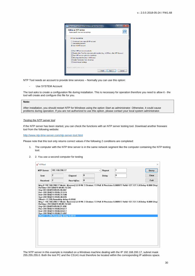
NTP Tool needs an account to provide time services – Normally you can use this option:
- Use SYSTEM Account The tool asks to create a configuration file during installation. This is necessary for operation therefore you need to allow it - the tool will create and configure this file for you.
Note: After installation, you should restart NTP for Windows using the option Start as administrator. Otherwise, it could cause problems during operation. If you are not authorized to use this option, please contact your local system administrator.
Testing the NTP server tool
If the NTP server has been started, you can check the functions with an NTP server testing tool. Download another freeware
tool from the following website:
http://www.ntp-time-server.com/ntp-server-tool.html
Please note that this tool only returns correct values if the following 2 conditions are completed:
1. The computer with the NTP time server is in the same network segment like the computer containing the NTP testing
tool.
2. 2. You use a second computer for testing
The NTP server in this example is installed on a Windows machine dealing with the IP 192.168.200.17, subnet mask 255.255.255.0. Both the test PC and the CS141 must therefore be located within the corresponding IP address space.

v.: 2.0.5 2018-05-24 / FW1.68
31
Otherwise, the NTP server service will not work. Set up time manually
Enter Date and Time values manually
Save values and set System time
Some cases require to enter time manually. with pressing Set System Time, the CS141 will accept the new values and overwrite the current system time. The result can be seen instantly under Current System Time. To prevent automatic time correction, delete NTP Server. Please ensure the UPS does not correct it, too.
Note: The synchronization with a time server is performed automatically by the operating system inside of the CS141 device. Therefore, you will not find it in event log files. "Device time synchronized" refers to a special function of the UPS and indicates the internal clock of the UPS has been readjusted by the CS141. Exception: You have changed the settings and restarted the NTP service using the Synchronize with Timeserver function.in this case, the according user interface subsystem recognizes a manually triggered execution and will insert a log entry.
User management
Opens the folder System
System overview Setup Wizard
User management
The CS141 provides a preset for 3 user profiles to assign different system privileges: Settings that do not correspond to the corresponding user profile are hidden as soon as the corresponding user logs on. The user names as well as the privileges coming with the users are hard-coded by the CS141. Administrators are only allowed to change passwords: The administrator User admin Default-password: cs141-snmp Due to its function, the administrator gets the full range of configuration options. The administrator manages network and mail settings. Furthermore, he is the only user with permission to change the landscape of connected devices. The technician User engineer Default password: engineer The technician’s user account is restricted to his area of responsibilities - he may access to the functions that relate to technical action. He has the ability to customize and configure available devices and performs the necessary adjustments.
v.: 2.0.5 2018-05-24 / FW1.68
32
Guest access User guest Default Password: guest The guest access is designed to view system monitors without triggering additional functions. Due to this fact, a special feature comes with this user: If necessary, password queries can be deactivated by administrators.
Enable/disable password query
Enter a new password Verify password
To use guest access without password query, set the mark for Anonymous Access. Otherwise the CS141 will ask for a valid password.
Note: The user admin is allowed to manage COM interfaces, but not the user engineer. This is necessary due to the fact, attached monitoring systems may need to be prepared for a change inside the hardware landscape before local hardware or components will be disabled for local maintenance duties. If a technician already "starts" before administrators stop according monitoring services, wrong alarm states may cause trouble.
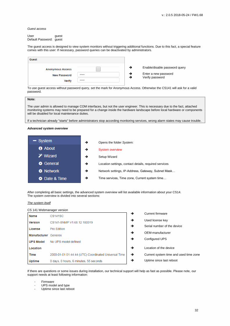
Advanced system overview
Opens the folder System: System overview Setup Wizard Location settings, contact details, required services Network settings, IP-Address, Gateway, Subnet Mask… Time services, Time zone, Current system time…
After completing all basic settings, the advanced system overview will list available information about your CS14. The system overview is divided into several sections: The system itself CS 141 Webmanager version
Current firmware
Used license key
Serial number of the device
OEM-manufacturer
Configured UPS
Location of the device
Current system time and used time zone
Uptime since last reboot
If there are questions or some issues during installation, our technical support will help as fast as possible. Please note, our support needs at least following information:
- Firmware - UPS model and type - Uptime since last reboot

v.: 2.0.5 2018-05-24 / FW1.68
33
Hardware
System serial number
Hardware revision
In 2018, there are two CS141 hardware revisions available on the market. They differ in some aspects inside: All CS141 that are built in 2018 uses a new flash kit. Due to this fact there are some registrations to firmware versions: Earlier versions of CS141 are fully update compatible, but the newer version is designed to run from firmware 1.66.xx onwards. In support cases it is essentially required to know your hardware release:
- bch16 can run earlier firmware version than 1.66.XX - bch 8 runs with minimum firmware 1.66.XX
Ensure to use the correct firmware, if you are using bhh 8 – feature, old firmware will not run.
Network settings
MAC-Address of yourCS141
Configured IP Address
Configured Subnet Mask
Configured Gateway
Configured DNS-Server
The network settings show the current configuration:
MAC address: The Media Access Control is a worldwide unique address to identify a network device. This
address is given by the manufacturer and cannot be changed.
IP-Address: Shows current IP address assigned to this device. In configuration mode, the default IP
10.10.10.10 is set, even if the IP address configured by administrators differs.
Gateway: Defines the network device that is allowed to accept and serve requests to the Internet. By
default, the configuration mode uses IP 10.10.10.1
DNS The DNS server provides the translation of names and IP addresses into reachable destinations
within networks. In configuration mode, it is the IP 10.10.10.1
Connectivity
Devices according to COM 1
Services this CS141 device
provides
Connectivity allows a general overview of the options the CS141 currently provides.
Devices thereby merely indicates a UPS can be connected hardwarely to the CS141, but not the kind of model. Services define
the software-related services installed and started on the CS141 to communicate with additional devices as well as software.
v.: 2.0.5 2018-05-24 / FW1.68
34
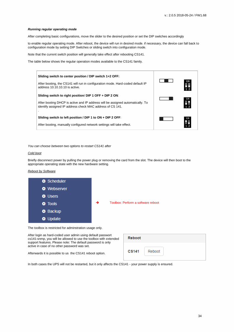
Running regular operating mode
After completing basic configurations, move the slider to the desired position or set the DIP switches accordingly
to enable regular operating mode. After reboot, the device will run in desired mode. if necessary, the device can fall back to
configuration mode by setting DIP Switches or sliding switch into configuration mode.
Note that the current switch position will generally take effect after rebooting CS141.
The table below shows the regular operation modes available to the CS141 family.
You can choose between two options to restart CS141 after
Cold boot
Briefly disconnect power by pulling the power plug or removing the card from the slot. The device will then boot to the
appropriate operating state with the new hardware setting.
Reboot by Software
Toolbox: Perform a software reboot
The toolbox is restricted for adminstration usage only. After login as hard-coded user admin using default passwort cs141-snmp, you will be allowed to use the toolbox with extended support features. Please note: The default password is only active in case of no other password was set. Afterwards it is possible to us the CS141 reboot option. In both cases the UPS will not be restarted, but it only affects the CS141 - your power supply is ensured.
Sliding switch to center position / DIP switch 1+2 OFF: After booting, the CS141 will run in configuration mode. Hard-coded default IP address 10.10.10.10 is active.
Sliding switch to right position/ DIP 1 OFF + DIP 2 ON:
After booting DHCP is active and IP address will be assigned automatically. To
identify assigned IP address check MAC address of CS 141.
.
Sliding switch to left position / DIP 1 to ON + DIP 2 OFF:
After booting, manually configured network settings will take effect.
v.: 2.0.5 2018-05-24 / FW1.68
35
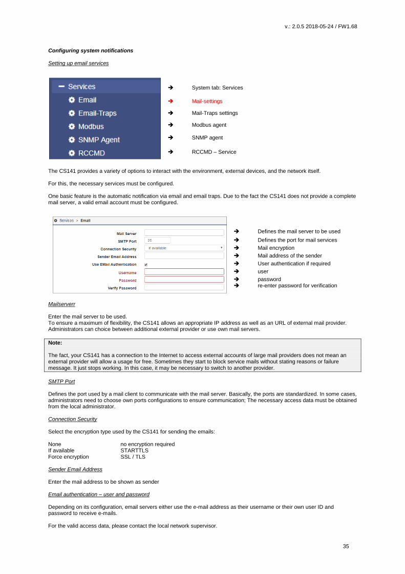
Configuring system notifications Setting up email services
System tab: Services
Mail-settings
Mail-Traps settings
Modbus agent
SNMP agent
RCCMD – Service
The CS141 provides a variety of options to interact with the environment, external devices, and the network itself. For this, the necessary services must be configured. One basic feature is the automatic notification via email and email traps. Due to the fact the CS141 does not provide a complete mail server, a valid email account must be configured.
Defines the mail server to be used
Defines the port for mail services
Mail encryption
Mail address of the sender
User authentication if required
user
password re-enter password for verification
Mailserverr Enter the mail server to be used. To ensure a maximum of flexibility, the CS141 allows an appropriate IP address as well as an URL of external mail provider. Administrators can choice between additional external provider or use own mail servers.
Note: The fact, your CS141 has a connection to the Internet to access external accounts of large mail providers does not mean an external provider will allow a usage for free. Sometimes they start to block service mails without stating reasons or failure message. It just stops working. In this case, it may be necessary to switch to another provider.
SMTP Port Defines the port used by a mail client to communicate with the mail server. Basically, the ports are standardized. In some cases, administrators need to choose own ports configurations to ensure communication; The necessary access data must be obtained from the local administrator. Connection Security Select the encryption type used by the CS141 for sending the emails: None no encryption required If available STARTTLS Force encryption SSL / TLS Sender Email Address Enter the mail address to be shown as sender Email authentication – user and password Depending on its configuration, email servers either use the e-mail address as their username or their own user ID and password to receive e-mails. For the valid access data, please contact the local network supervisor.
v.: 2.0.5 2018-05-24 / FW1.68
36
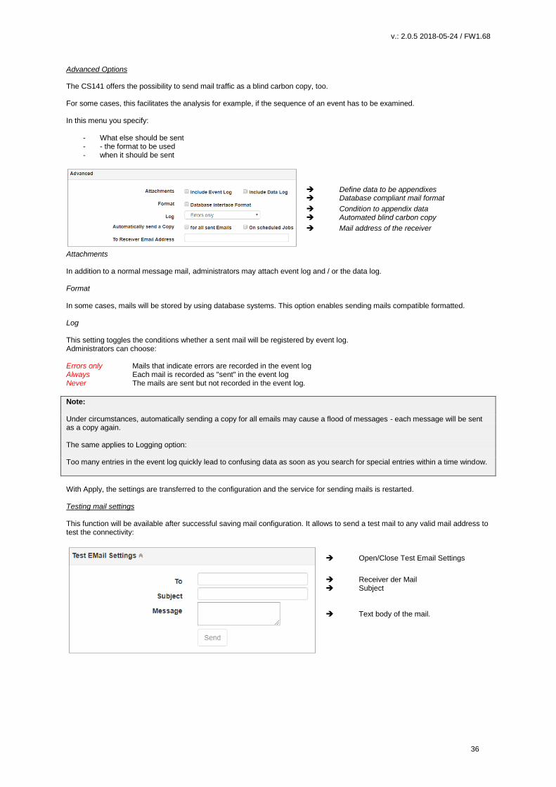
Advanced Options
The CS141 offers the possibility to send mail traffic as a blind carbon copy, too. For some cases, this facilitates the analysis for example, if the sequence of an event has to be examined. In this menu you specify:
- What else should be sent - - the format to be used - when it should be sent
Define data to be appendixes
Database compliant mail format
Condition to appendix data
Automated blind carbon copy
Mail address of the receiver
Attachments In addition to a normal message mail, administrators may attach event log and / or the data log. Format In some cases, mails will be stored by using database systems. This option enables sending mails compatible formatted. Log This setting toggles the conditions whether a sent mail will be registered by event log. Administrators can choose: Errors only Mails that indicate errors are recorded in the event log Always Each mail is recorded as "sent" in the event log Never The mails are sent but not recorded in the event log.
Note: Under circumstances, automatically sending a copy for all emails may cause a flood of messages - each message will be sent as a copy again. The same applies to Logging option: Too many entries in the event log quickly lead to confusing data as soon as you search for special entries within a time window.
With Apply, the settings are transferred to the configuration and the service for sending mails is restarted. Testing mail settings This function will be available after successful saving mail configuration. It allows to send a test mail to any valid mail address to test the connectivity:
Open/Close Test Email Settings
Receiver der Mail Subject Text body of the mail.
v.: 2.0.5 2018-05-24 / FW1.68
37
Mail error message
Connection refused This error indicates CS141 cannot establish a connection to the mail server it is configured to.
The reasons for this behavior can vary. some reasons may be: - wrong encryption type - wrong or closed ports - DNS / Gateway settings are wrong ... or the fact, a mail provider does not allow this kind of mail traffic. Email-Traps Mail trap messages are automatically generated by industrial systems for information and status reports. Retrieved and evaluated by a corresponding recipient they are very useful inside semi- or full-automated infrastructures. The difference to a normal email is that there is no option to enter custom text or define a different recipient. A valid mail account must be deposited to send mail traps. For details, please refer the Chapter Configuring UPS In some cases, administrators need to use different mail accounts - if they choose to one Email account, CS141 offers to copy registration data directly from standard mail configuration:
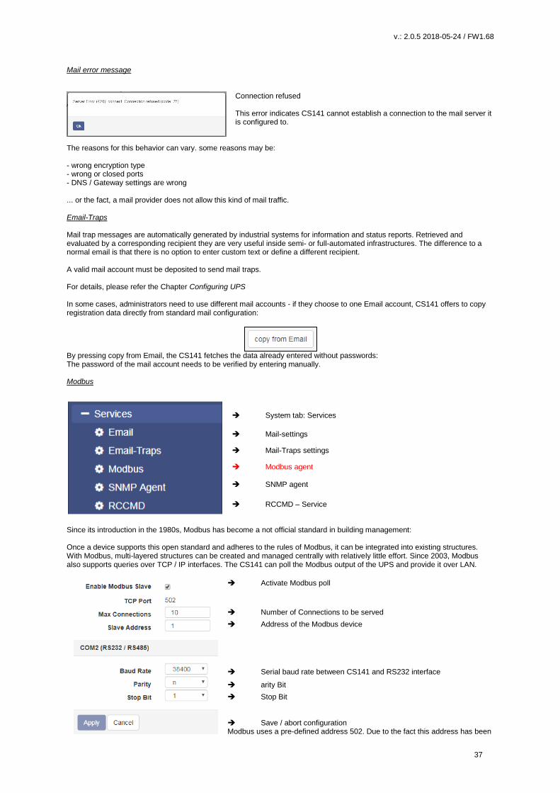
By pressing copy from Email, the CS141 fetches the data already entered without passwords: The password of the mail account needs to be verified by entering manually. Modbus
System tab: Services
Mail-settings
Mail-Traps settings
Modbus agent
SNMP agent
RCCMD – Service
Since its introduction in the 1980s, Modbus has become a not official standard in building management: Once a device supports this open standard and adheres to the rules of Modbus, it can be integrated into existing structures. With Modbus, multi-layered structures can be created and managed centrally with relatively little effort. Since 2003, Modbus also supports queries over TCP / IP interfaces. The CS141 can poll the Modbus output of the UPS and provide it over LAN.
Activate Modbus poll
Number of Connections to be served
Address of the Modbus device
Serial baud rate between CS141 and RS232 interface
arity Bit
Stop Bit Save / abort configuration Modbus uses a pre-defined address 502. Due to the fact this address has been

v.: 2.0.5 2018-05-24 / FW1.68
38
established as an international standard, this address cannot be changed. SNMP Agent
System tab: Services
Mail-settings
Mail-Traps settings
Modbus agent
SNMP agent
RCCMD – Service
developed by the IETF the Simple Network Management Protocol is designed for monitoring and controlling network elements from a central station. The protocol controls the communication traffic between monitored devices and monitoring stations: SNMP describes the structure of the data packets that can be sent as well as the entire communication process. The CS141 can fully be integrated into a network with SNMP monitoring. The build-in SNMP agent regulates both - receiving and sending corresponding requests
Toggle SNMP agent
Version number Configured users and
groups
Note: SNMP V1.0 is not officially supported by the CS141. We recommend the use version 2.0 upward. However, since V1.0 is largely included in V2.0, the CS141 will respond to SNMP-V1 requests, but using V1.0 will be out of official supporter’s guidance.
The CS141 supports SNMP v2 as well as SNMP v3: The difference that SNMP v2 and v3: SNMP v2 works on behalf of legitimating an IP address inside user communities, SNMP v3 is based on direct user permissions with name and password. After enabling the SNMP agent, the CS141 starts providing SNMP communication.
v.: 2.0.5 2018-05-24 / FW1.68
39
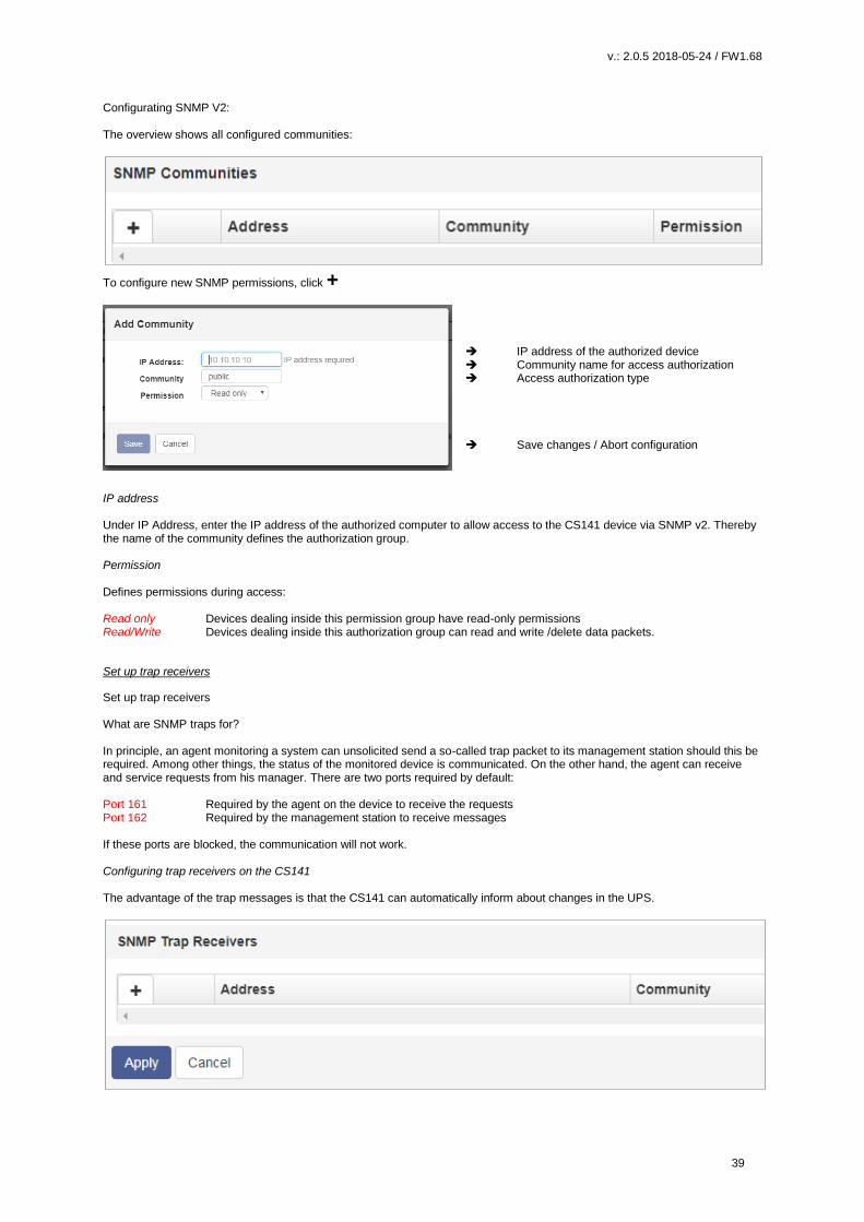
Configurating SNMP V2: The overview shows all configured communities:
To configure new SNMP permissions, click +
IP address of the authorized device Community name for access authorization Access authorization type Save changes / Abort configuration
IP address Under IP Address, enter the IP address of the authorized computer to allow access to the CS141 device via SNMP v2. Thereby the name of the community defines the authorization group. Permission Defines permissions during access: Read only Devices dealing inside this permission group have read-only permissions Read/Write Devices dealing inside this authorization group can read and write /delete data packets.
Set up trap receivers
Set up trap receivers What are SNMP traps for? In principle, an agent monitoring a system can unsolicited send a so-called trap packet to its management station should this be required. Among other things, the status of the monitored device is communicated. On the other hand, the agent can receive and service requests from his manager. There are two ports required by default: Port 161 Required by the agent on the device to receive the requests Port 162 Required by the management station to receive messages If these ports are blocked, the communication will not work. Configuring trap receivers on the CS141 The advantage of the trap messages is that the CS141 can automatically inform about changes in the UPS.

v.: 2.0.5 2018-05-24 / FW1.68
40
To add a new trap reciever, click +,
Since trap messages are sent exclusively to inform about status
changes, no read / write operations permissions are required.
Enter the recipient's IP address as well as a valid community.
With Save button, CS141 takes over the settings and the SNMP
agent will be restarted. The CS141 will not neet to be rebooted.
Trap receiver test
The Trap receiver can be subsequently tested by pressing the test button. The corresponding test message should be displayed
directly in your management program.
Note:
Trap messages are automatically generated messages that do not request confirmation - therefore an agent does never know if
his trap message have arrived. Du to this fact, a reception logging is not possible.
Configurating SNMP v3
The overview shows all configured users
Since SNMPv3 is user-based, you need to configure single users instead of communities. Click +to configure new user
Add user name
Toggle Read/write permission
Access control to CS141
Save changes / Abort
configuration
User
SNMP v3 dispenses with the possibility of setting up authorized IP addresses and user groups. Administrators need to add a
local user inside the CS141 device.
v.: 2.0.5 2018-05-24 / FW1.68
41
Read-only / Read Write
As a standard, any user gets the permission for both - reading and writing. In some cases, this may be not allowed by
administrators. To prevent SNMP users from writing data, activate the option Read only
Authentication
Defines security level and password control to access the CS141 device using SNMP v3:
No security no passwords or encryption is required
Authenticities Single password request.
Authentication and Privacy The connection is additionally encrypted and two passwords are required.
Note:
In addition to access data, the encryption type must be identical. Otherwise no connection will be established.
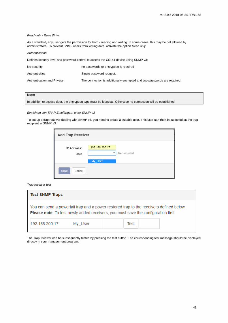
Einrichten von TRAP Empfängern unter SNMP v3 To set up a trap receiver dealing with SNMP v3, you need to create a suitable user. This user can then be selected as the trap recipient in SNMP v3.
Trap receiver test
The Trap receiver can be subsequently tested by pressing the test button. The corresponding test message should be displayed directly in your management program.

v.: 2.0.5 2018-05-24 / FW1.68
42
UPS Configuration The external Interface
COM-Port Settings
Configure the UPS Configure the Event Handling Advanced UPS functions Custom defined system events
Depending on the design and model, the CS141 provides up to three additional COM ports fulfilling different functions. To start configuration, go to Devices and press Setup. Please note in some cases submenus will appear to specify functions of devices connected to CS141. Pre-check of settings:
By default, UPS is selected to be used with COM1. If this setting has been changed by earlier usage, open the drop-down menu and select UPS. With Apply, the new setting is saved and the CS141 starts the corresponding services that are necessary to start communication with a UPS. By activating this function, a general dummy is set first to enable corresponding menus for further access. Successful Activation routines will be shown inside the interactive bar on the top of the screen.
CS141 starts the UPS functionality The dummy has been loaded and the UPS menus are accessible
The UPS monitor shows „No UPS model defined” and indicates the fact of a UPS dummy. In fact, some UPS specific menus are not available – they can only be run by the usage of an according UPS model.

v.: 2.0.5 2018-05-24 / FW1.68
43
Special feature: The Pipe Through function
COM port 2 is a flexible option for different devices and functionalities:
- Sensors
- External SMS modems
- Modbus capability
- Pipe Through functionality
In UPS configuration the pipe-through function is an interesting
feature:
This function allows to loop through the signals coming from the UPS
at COM port 1 and output it directly at COM port 2.
A second CS141 can be connected to COM 2 of the first device
instead of the UPS.
This feature allows to provide information about the UPS to two
physically isolated networks. Furthermore, administrators are able to
implement a shutdown solution independently to neighbored
networks.
In protected environments, CS141 provides management strategies of different networks that access the same UPS. The configuration of Pipe Through will be done at the Webmanager connected to the UPS. The second Web Manager is configured as described on COM 1 but is connected to the COM2 port of the first Web Manager instead of the UPS.

v.: 2.0.5 2018-05-24 / FW1.68
44
Note: When using the pipe-through function, be sure to set the correct COM2 port to Pipe Through and set the same UPS with identical values on both CS141s. All other settings may differ.
Setup of the UPS The external Interface
COM-Port Settings
Configure the UPS Configure the Event Handling Advanced UPS functions Custom defined system events
After configuring COM1 to use UPS, go to the submenu UPS and forward to Setup: Automatic UPS search and setup feature The CS141 provides an automatic detection mode to find the UPS connected to the device. After successfull UPS search, the CS141 will set up all basic settings automatically. Please note, in some cases the values may differ from default values - as an example, if additional batteries have been inistalled. These values neet to be corrected manually.
Choose UPS model
Maximum power the UPS can provide
Maxim system load
Maximum time in autonomous mode at 100% system load
Recharge time of the batteries after depleting.
Serial data connection speed
Cable type to be used
Select UPS ID
Installation date of the batteries
Batteries should be changed after time of usage
UPS shutdown timer to prevent batterie damage
Save settings / Abort configurating
Normally, the UPS itself provides the necessary data to ensure operation. The values configured in this menu become important as soon as the UPS protocol does not support the corresponding data: Based on the data situation, the CS141 will independently calculate the corresponding battery runtime. In general, these settings do not need to be changed a UPS model is selectable - the optimal configuration has already been set. Administrators who wish to use a configuration that differs from standard settings or need to run a UPS that does not provide required data, please contact your local UPS dealer to get the correct settings.
Note:
By default, OEM ID 12 is set for GENEREX SYSTEMS. administrators who want to use a UPS build by a special manufacturer should take a look at the download area of www.generex.de - Just search for the firmware for your UPS manufacturer and install it as a regular firmware update. Afterwards the corresponding UPS models will be available.
v.: 2.0.5 2018-05-24 / FW1.68
45
Customizable information about the UPS:
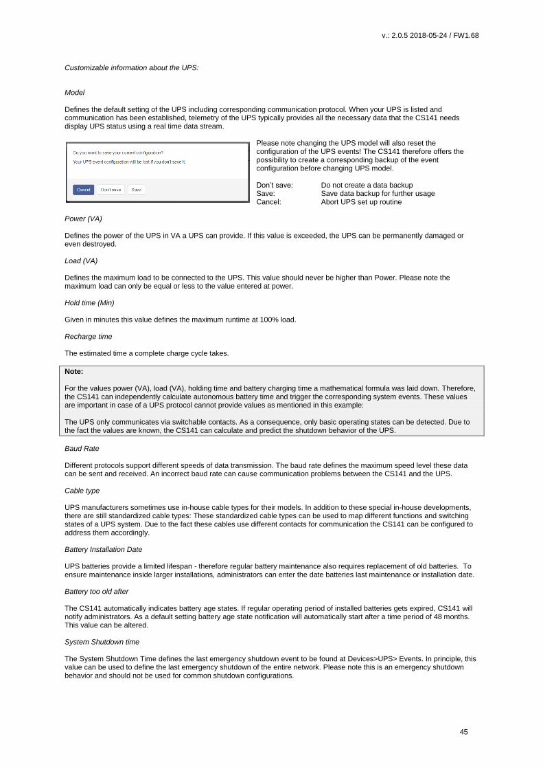
Model Defines the default setting of the UPS including corresponding communication protocol. When your UPS is listed and communication has been established, telemetry of the UPS typically provides all the necessary data that the CS141 needs display UPS status using a real time data stream.
Please note changing the UPS model will also reset the configuration of the UPS events! The CS141 therefore offers the possibility to create a corresponding backup of the event configuration before changing UPS model. Don’t save: Do not create a data backup Save: Save data backup for further usage Cancel: Abort UPS set up routine
Power (VA) Defines the power of the UPS in VA a UPS can provide. If this value is exceeded, the UPS can be permanently damaged or even destroyed. Load (VA) Defines the maximum load to be connected to the UPS. This value should never be higher than Power. Please note the maximum load can only be equal or less to the value entered at power. Hold time (Min) Given in minutes this value defines the maximum runtime at 100% load. Recharge time The estimated time a complete charge cycle takes.
Note: For the values power (VA), load (VA), holding time and battery charging time a mathematical formula was laid down. Therefore, the CS141 can independently calculate autonomous battery time and trigger the corresponding system events. These values are important in case of a UPS protocol cannot provide values as mentioned in this example: The UPS only communicates via switchable contacts. As a consequence, only basic operating states can be detected. Due to the fact the values are known, the CS141 can calculate and predict the shutdown behavior of the UPS.
Baud Rate Different protocols support different speeds of data transmission. The baud rate defines the maximum speed level these data can be sent and received. An incorrect baud rate can cause communication problems between the CS141 and the UPS. Cable type UPS manufacturers sometimes use in-house cable types for their models. In addition to these special in-house developments, there are still standardized cable types: These standardized cable types can be used to map different functions and switching states of a UPS system. Due to the fact these cables use different contacts for communication the CS141 can be configured to address them accordingly. Battery Installation Date UPS batteries provide a limited lifespan - therefore regular battery maintenance also requires replacement of old batteries. To ensure maintenance inside larger installations, administrators can enter the date batteries last maintenance or installation date. Battery too old after The CS141 automatically indicates battery age states. If regular operating period of installed batteries gets expired, CS141 will notify administrators. As a default setting battery age state notification will automatically start after a time period of 48 months. This value can be altered. System Shutdown time The System Shutdown Time defines the last emergency shutdown event to be found at Devices>UPS> Events. In principle, this value can be used to define the last emergency shutdown of the entire network. Please note this is an emergency shutdown behavior and should not be used for common shutdown configurations.

v.: 2.0.5 2018-05-24 / FW1.68
46
UPS-ID Large UPS systems can contain more than one UPS module - these modules are queried via a unique ID. The ID 0 is some kind of broadcast to allow CS141 recognizing and managing the number of UPS modules itself. By Changing this value CS141 will only display the module answering to this unique ID. Apply / Cancel Apply allows you to save and restart the UPS service on the CS141. Cancel will abort the configuration process and withdraw all settings – they need to be entered again. Battery Health Level feature
The battery health level will be automatically provided by CS141 inside the UPS configuration menu if the UPS connected to the
CS141 principally carries out battery testing but does not return a reporting value for "Battery test passed / faulty". Thus, the
result needs to be determined by comparing two measurements:
Before battery test starts, the battery voltage will be recorded. This value will be compared with the battery voltage to be found
after finishing the battery test. The Battery Health Level (%) setting defines the maximum percentage deviation these two values
may differ. On exceeding this value, a battery failure will be displayed.
The default setting for this test is 10% deviation - but can be specified with a custom value between 5% and 30%.
Special feature: The RFC1628 UPS interface
In some cases, UPS manufacturers supply systems that the CS141 can not communicate to. As an example known probrems
are the card does not fit to the slot, or that the data stream sent by the UPS is not compatible formatted:
UPS manufacturers have installed their own SNMP card, which offers similar functions but may not be compatible to your
flexible and powerful GENEREX software environment. To ensure compatibility, the CS141 Web Manager offers the option to
connec to any card via SNMP. The condition is that the RFC 1628 MIB is supported by the target card. In order to use this
function, it is first necessary to configure a corresponding SNMP Agent at the destinated UPS.
After that enter the access data in the CS141 UPS menu. The CS141 will restart required services an establish a connection to
the destination card.

v.: 2.0.5 2018-05-24 / FW1.68
47
Setting up the destination card under SNMP v2 at CS141
Choose UPS model
Select SNMP Version
IP-Adresse oft he destination
Select SNMP Community
Save settings / abord
configuration dialog
Modell
Choos l SNMP UPS-RFC 128 compliant as UPS model
SNMP-Version
Dependig on the configuration of your destinated SNMP card, choose SNMP version 1 or 2
SNMP Community
Enter the SNMP Community configured at destinated SNMP card
Save/Abort
Abort will withdraw all settings, save will restart required services. After restarting the services CS141 will automaticalle
establish a communication to destinated SNMP card.
Note:
What is the difference between the RF1628 UPS interface and the APC Smart Network?
In principle, the APC card can handle the RFC1628 standard - you will be able to query basic information about the UPS.
However, the APC cards often uses their own OIDs. These OIDs are specific to AP and not conform to the RFC1628 standards.
Therefore, it is recommended to use the APC Smart network setting instead of RFC1628 interface.
Setting up the destination card under SNMP v3 at CS141
Choose UPS model
Choose / change SNMP Version
IP address of the target system
SNMP User
Encryption method
MD5/SHA password
ES/AES password
Apply / abort The CS141 supports SNMP v1, v2, and v3 in this mode of operation. Enter the access data for the destination card according to your configuration and click Apply

v.: 2.0.5 2018-05-24 / FW1.68
48
UPS-Monitor: Checking UPS Settings Realtime UPS monitoring screen Realtime sensor monitoring screen
In case of all settings have been entered correctly, administrators can check the UPS's current status in real time by using the
UPS monitor. Although the representation may differ depending on the manufacturer and model, some data such as the
selected model will be shown:
UPS functions
COM-Port Settings
Configure the UPS Configure the Event Handling Advanced UPS functions Custom defined system events
The UPS Functions menu contains options to perform tests sequences or to configure build-in special functions a UPS may provide. They are tailored to the UPS model used to represent its functionality. As a consequence, the functions displayed for this menu item can vary - some UPSs only allow the on / off state as well as a single test-button, others provide more functionality.
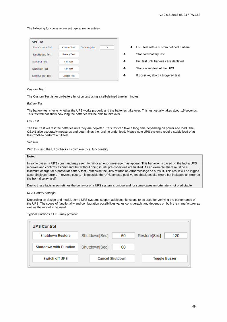
v.: 2.0.5 2018-05-24 / FW1.68
49
The following functions represent typical menu entries:
UPS test with a custom defined runtime
Standard battery test Full test until batteries are depleted Starts a self-test of the UPS If possible, abort a triggered test
Custom Test The Custom Test is an on-battery function test using a self-defined time in minutes. Battery Test The battery test checks whether the UPS works properly and the batteries take over. This test usually takes about 15 seconds. This test will not show how long the batteries will be able to take over. Full Test The Full Test will test the batteries until they are depleted. This test can take a long time depending on power and load. The CS141 also accurately measures and determines the runtime under load. Please note UPS systems require stable load of at least 25% to perform a full test. Self test With this test, the UPS checks its own electrical functionality
Note:
In some cases, a UPS command may seem to fail or an error message may appear. This behavior is based on the fact a UPS
receives and confirms a command, but without doing it until pre-conditions are fulfilled. As an example, there must be a
minimum charge for a particular battery test - otherwise the UPS returns an error message as a result. This result will be logged
accordingly as "error". In reverse cases, it is possible the UPS sends a positive feedback despite errors but indicates an error on
the front display itself.
Due to these facts in sometimes the behavior of a UPS system is unique and for some cases unfortunately not predictable.
UPS Control settings
Depending on design and model, some UPS systems support additional functions to be used for verifying the performance of
the UPS. The scope of functionality and configuration possibilities varies considerably and depends on both the manufacturer as
well as the model to be used.
Typical functions a UPS may provide:

v.: 2.0.5 2018-05-24 / FW1.68
50
Switchable output
Depending on the design, some UPS systems support switchable output ports.
Note:
Depending on the performance class, UPS systems are equipped differently. Due to this fact, the scope of functions varies.
Event handling
COM-Port Settings
Configure the UPS Configure the Event Handling Advanced UPS functions Custom defined system events
There are many incidents that may require the operation of a UPS. In other cases, devices connected to the UPS may be harmed by different events. These events could be as an example - the failure of the main power supply, - the restoration of the main power supply, - a defect from inside the UPS prevents taking over to autonomous battery mode - batteries are depleted and main power is still missing As a full-fledged manager, the CS141 has the ability to respond to incidents independently, inform responsible personal and even manage event chains to provide a complete shutdown solution inside complex interdependent networks. Defining jobs for an event System events are highly dependent on the UPS model to be used and vary in both - designation as well as abundance of possibilities. Furthermore, administrators will find interesting conceptional issues according to the interplay of events and counter-events: An event receives an action, a job. This job will be executed when the event occurs. These jobs differ in central role as well as its direct function:
- Information These jobs can be executed as often as desired and only fulfill the purpose of the information. Depending on the configuration, information can be send once or cyclically as long as an event is pending - the nature of the event does not matter. If the situation changes and the event does not come to fruition, an according job will not continue.
- Action These jobs are designed to switch, trigger, start emergency routines, etc. These jobs are triggered as soon as an event occurs. They differ from information jobs due to the fact administrators have to terminate these jobs by using corresponding counter- rotating jobs. In some cases, there are counter-events to be used, others need to be configured manually.
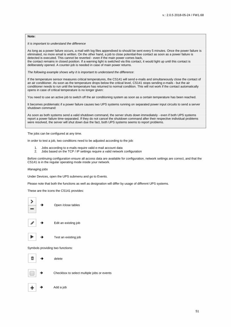
v.: 2.0.5 2018-05-24 / FW1.68
51
Note: It is important to understand the difference As long as a power failure occurs, a mail with log files appendixed to should be sent every 5 minutes. Once the power failure is eliminated, no more email is written. On the other hand, a job to close potential-free contact as soon as a power failure is detected is executed. This cannot be reverted - even if the main power comes back, the contact remains in closed position. If a warning light is switched via this contact, it would light up until this contact is deliberately opened. A counter-job is needed in case of main power returns. The following example shows why it is important to understand the difference: If the temperature sensor measures critical temperatures, the CS141 will send e-mails and simultaneously close the contact of an air conditioner. As soon as the temperature drops below the critical level, CS141 stops sending e-mails - but the air conditioner needs to run until the temperature has returned to normal condition. This will not work if the contact automatically opens in case of critical temperature is no longer given: You need to use an active job to switch off the air conditioning system as soon as a certain temperature has been reached. It becomes problematic if a power failure causes two UPS systems running on separated power input circuits to send a server shutdown command: As soon as both systems send a valid shutdown command, the server shuts down immediately - even if both UPS systems report a power failure time-separated. If they do not cancel the shutdown command after their respective individual problems were resolved, the server will shut down due the fact, both UPS systems seems to report problems.
The jobs can be configured at any time. In order to test a job, two conditions need to be adjusted according to the job:
1. Jobs according to e-mails require valid e-mail account data 2. Jobs based on the TCP / IP settings require a valid network configuration
Before continuing configuration ensure all access data are available for configuration, network settings are correct, and that the CS141 is in the regular operating mode inside your network. Managing jobs Under Devices, open the UPS submenu and go to Events. Please note that both the functions as well as designation will differ by usage of different UPS systems. These are the icons the CS141 provides:
Open /close tables
Edit an existing job
Test an existing job
Symbols providing two functions:
delete
Checkbox to select multiple jobs or events
Add a job
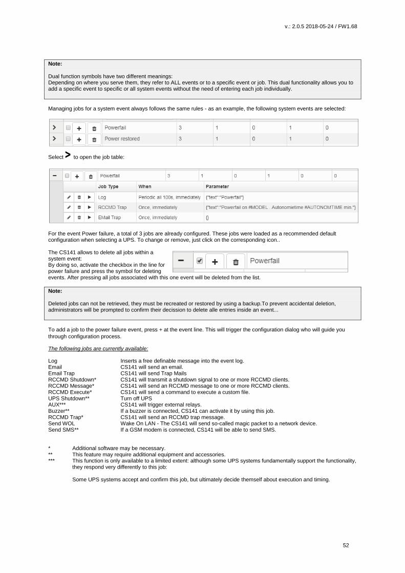
v.: 2.0.5 2018-05-24 / FW1.68
52
Note: Dual function symbols have two different meanings: Depending on where you serve them, they refer to ALL events or to a specific event or job. This dual functionality allows you to add a specific event to specific or all system events without the need of entering each job individually.
Managing jobs for a system event always follows the same rules - as an example, the following system events are selected:
Select > to open the job table:
For the event Power failure, a total of 3 jobs are already configured. These jobs were loaded as a recommended default configuration when selecting a UPS. To change or remove, just click on the corresponding icon.. The CS141 allows to delete all jobs within a system event: By doing so, activate the checkbox in the line for power failure and press the symbol for deleting events. After pressing all jobs associated with this one event will be deleted from the list.
Note: Deleted jobs can not be retrieved, they must be recreated or restored by using a backup.To prevent accidental deletion, administrators will be prompted to confirm their decission to delete alle entries inside an event...
To add a job to the power failure event, press + at the event line. This will trigger the configuration dialog who will guide you
through configuration process.
The following jobs are currently available:
Log Inserts a free definable message into the event log. Email CS141 will send an email. Email Trap CS141 will send Trap Mails RCCMD Shutdown* CS141 will transmit a shutdown signal to one or more RCCMD clients. RCCMD Message* CS141 will send an RCCMD message to one or more RCCMD clients. RCCMD Execute* CS141 will send a command to execute a custom file. UPS Shutdown** Turn off UPS AUX*** CS141 will trigger external relays. Buzzer** If a buzzer is connected, CS141 can activate it by using this job. RCCMD Trap* CS141 will send an RCCMD trap message. Send WOL Wake On LAN - The CS141 will send so-called magic packet to a network device. Send SMS** If a GSM modem is connected, CS141 will be able to send SMS.
* Additional software may be necessary. ** This feature may require additional equipment and accessories. *** This function is only available to a limited extent: although some UPS systems fundamentally support the functionality,
they respond very differently to this job: Some UPS systems accept and confirm this job, but ultimately decide themself about execution and timing.

v.: 2.0.5 2018-05-24 / FW1.68
53
UPS Shutdown definition Why is the job UPS shutdown a little bit tricky? A UPS performs a UPS shutdown to protect the batteries from a deep discharge. The UPS is physically shut down and turned
off. The time when a UPS performs this action or how it reacts to a triggered action by scheduler or via UPS functions already
varies even between the models within a manufacturer - in addition, each manufacturer uses its own definitions for to protect
batteries. But due to the fact the UPS has been physically turned off, counter events cannot be configured.
Configuring UPS Shutdown Choose the job
Time delay until system shutdown
Time delay until system restart
Toggle shutdown type
Shutdown time in seconds Defines how long the UPS should maintain operation before shutting down itself. Restore time in seconds When the main power supply is restored, the UPS waits for the preset value in seconds until it starts up again. Type With this setting the UPS will be turned off or turn on. Two different settings are possible:
1 The UPS switches off the outputs but remains in operation mode. 2 The UPS shuts down and turns off completely until the main power is restored.
How to use the job UPS Shutdown This job cannot map both settings together. Depending on the desired operation modes, at least two jobs are required. As an example, it is possible to use different jobs to complete the following sequence:
- Switch off outputs after 3 minutes - Shutdown the UPS after 4 minutes - Turn on the UPS 2 minutes after the main power supply is restored - Activate the outputs 15 minutes later
Note that the shutdown time and the restore time must be correctly nested for both jobs. In this case, enter either a 1 or a 2 depending on the desired event.
Search and show jobs
The Search function is a quick method to find jobs configured within events. The CS141 provides two basic options: Event contains… Search for a UPS event. By typing a part of an event all events according to the text fragment are listed. Jobs Lists events containing a number of jobs defined by this value. As an example, if you want to know how many events contain 3 jobs, enter 3. All events containing this number of jobs will be listed.

v.: 2.0.5 2018-05-24 / FW1.68
54
Configuring a Job
Press + at an event to open the job configuration dialog.
Different jobs provide different parameters to be configured
Example 1: Log – Enter the text CS141 shows at Event Log?
Example 2: RCCMD execute – Due to the fact RCCMD needs IP adress data, the parameters will change.
Timing The CS141 provides many system events a job can be assigned to. Some jobs allow to configure advanced timing:
Immediately, once As soon as an event happens, this job is executed at once and not repeated. After XXX seconds: The CS141 will wait a pre-defined time in seconds and than exucte the jobIf the event is
no longer active before time is up, the job will not be executed. Repeat all XXX seconds: The job is repeated cyclically until the event no longer is no longer active. After XXX seconds on battery: The event forces the UPS will to switch to autonomous mode.The job will be executed if
the UPS remains a pre-defined time in this state. For example, if 300 seconds are set, this job will only be executed if the UPS operates in autonomous reaches 300 seconds.
At XXX seconds remaining time: The job is executed when the remaining UPS operating time is reached or undershot.
Note based on the current load this time value becomes flexible. Time management of jobs The time management of jobs to be performed is difficult since one has to distinguish conceptually between two different points of view. The following example according to the event power failure illustrates the differences:

v.: 2.0.5 2018-05-24 / FW1.68
55
In case of a power outage, the UPS will take over power and protect the servers until ...
1. The batteries are depleted 2. Main power is available again
As soon as the UPS runs into autonomous mode, it will start two different timers: A linearly advancing time in seconds starting at 0. If a job is to be executed after 45 seconds, it will only be executed if the event is pending for at least 45 seconds. If the event is terminated before consequently the job is not executed.. A relative clock that counts backwards depending on the connected load currently used. This becomes tricky if the UPS will operate with a load of 100% If some of the machines connected to the UPS will be shut down after 3 minutes and cause the load to drop to 50%, it will take effect this way: Because of dropping load, the clock would jump from 4 minutes to 7.5 minutes. Both methods to count come with specific advantages and disadvantages: The first counter gives a clear time window to sequent jobs but ignores the actual remaining time of the UPS: If there are several small power failures in a row, a server shutdown would not work with a time delay of 5 minutes if battery power is left to ensure power a maximum of 4 minutes. The second counter is difficult to calculate and varies depending to the current load. As a consequence there may be a time lag
to execute configured tasks: 5 minutes remaining time cannot be achieved over a longer period of time, if the circumstances
increase the remaining time - for example some systems will be shut down at 7 minutes remaining time. On the other hand, a
predetermined Sequence of events can get mixed up as soon as the circumstances correct UPS uptime down and cause
normally sequentially configured jobs simultanously getting triggered.
Note: Basically a shutdown using remaining time is useful, since the actually existing battery charge can be included. If a special order must be observed for jobs, it makes sense to use the linearly forwarding clock for scheduling.
Adding jobs to several events Under circumstances, a configuration require multiple events be assigned the same job. To assign these jobs to more than one event, it is possible to select each event individually and to define this job.
To speed up the process select the events that should receive the same
job. Then click on the upper +.
By doing so, the same job is created inside the selected events. In diesem Fall wird der selbe Job bei jedem angewählten Ereignis angelegt. Activating the checkbox at the top row will advice the CS141 to add a job
is to all events. To start the job configuration dialog, click +.
Deleting a jobs If system events are no longer used inside a configuration, administrators should remove these jobs to prevent unexpected incidents.:
- Delete a job
Open event tab by clicking >
Choose the job you want to do delete and press the small trash icon. The job will be deleted immediately..
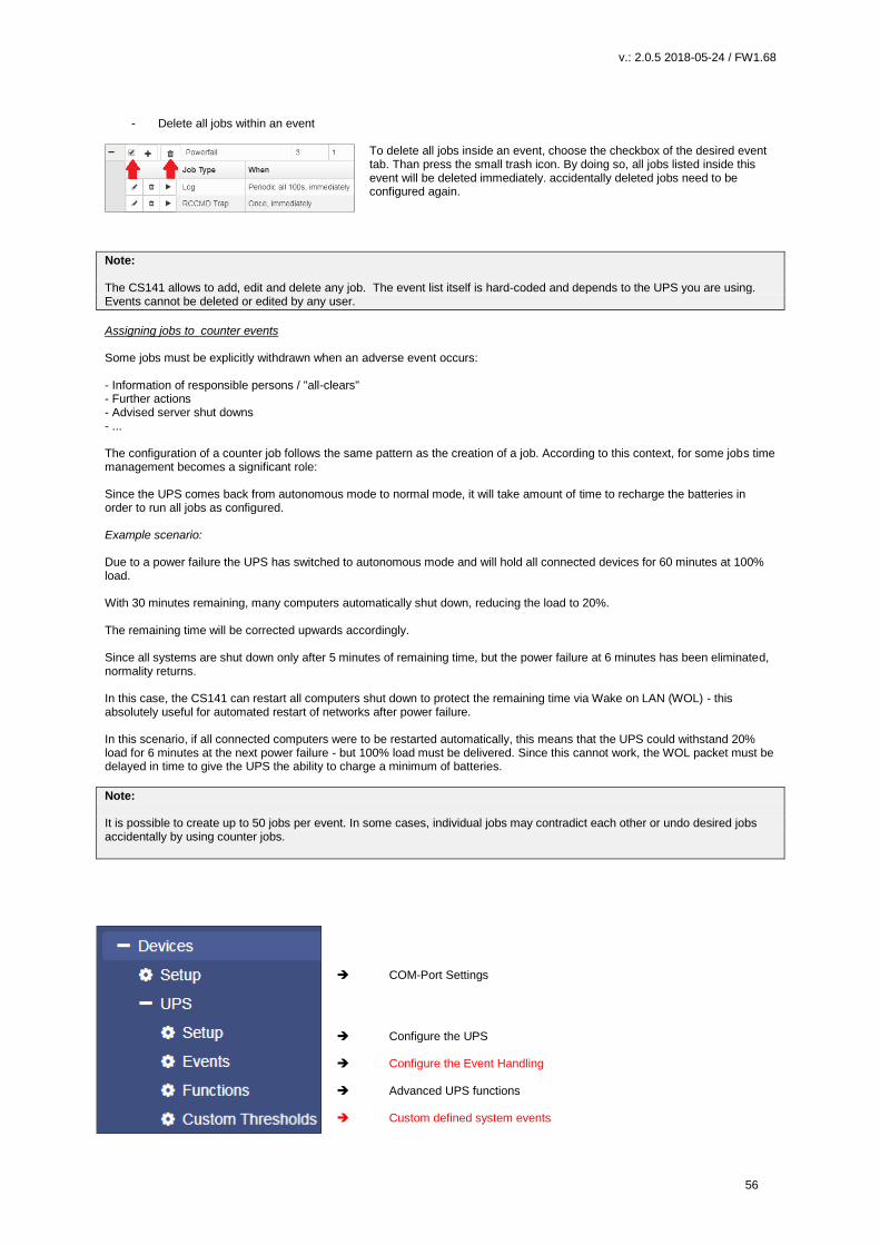
v.: 2.0.5 2018-05-24 / FW1.68
56
- Delete all jobs within an event
To delete all jobs inside an event, choose the checkbox of the desired event tab. Than press the small trash icon. By doing so, all jobs listed inside this event will be deleted immediately. accidentally deleted jobs need to be configured again.
Note: The CS141 allows to add, edit and delete any job. The event list itself is hard-coded and depends to the UPS you are using. Events cannot be deleted or edited by any user.
Assigning jobs to counter events Some jobs must be explicitly withdrawn when an adverse event occurs: - Information of responsible persons / "all-clears" - Further actions - Advised server shut downs - ... The configuration of a counter job follows the same pattern as the creation of a job. According to this context, for some jobs time management becomes a significant role: Since the UPS comes back from autonomous mode to normal mode, it will take amount of time to recharge the batteries in order to run all jobs as configured. Example scenario: Due to a power failure the UPS has switched to autonomous mode and will hold all connected devices for 60 minutes at 100% load. With 30 minutes remaining, many computers automatically shut down, reducing the load to 20%. The remaining time will be corrected upwards accordingly. Since all systems are shut down only after 5 minutes of remaining time, but the power failure at 6 minutes has been eliminated, normality returns. In this case, the CS141 can restart all computers shut down to protect the remaining time via Wake on LAN (WOL) - this absolutely useful for automated restart of networks after power failure. In this scenario, if all connected computers were to be restarted automatically, this means that the UPS could withstand 20% load for 6 minutes at the next power failure - but 100% load must be delivered. Since this cannot work, the WOL packet must be delayed in time to give the UPS the ability to charge a minimum of batteries.
Note: It is possible to create up to 50 jobs per event. In some cases, individual jobs may contradict each other or undo desired jobs accidentally by using counter jobs.
COM-Port Settings
Configure the UPS Configure the Event Handling Advanced UPS functions Custom defined system events
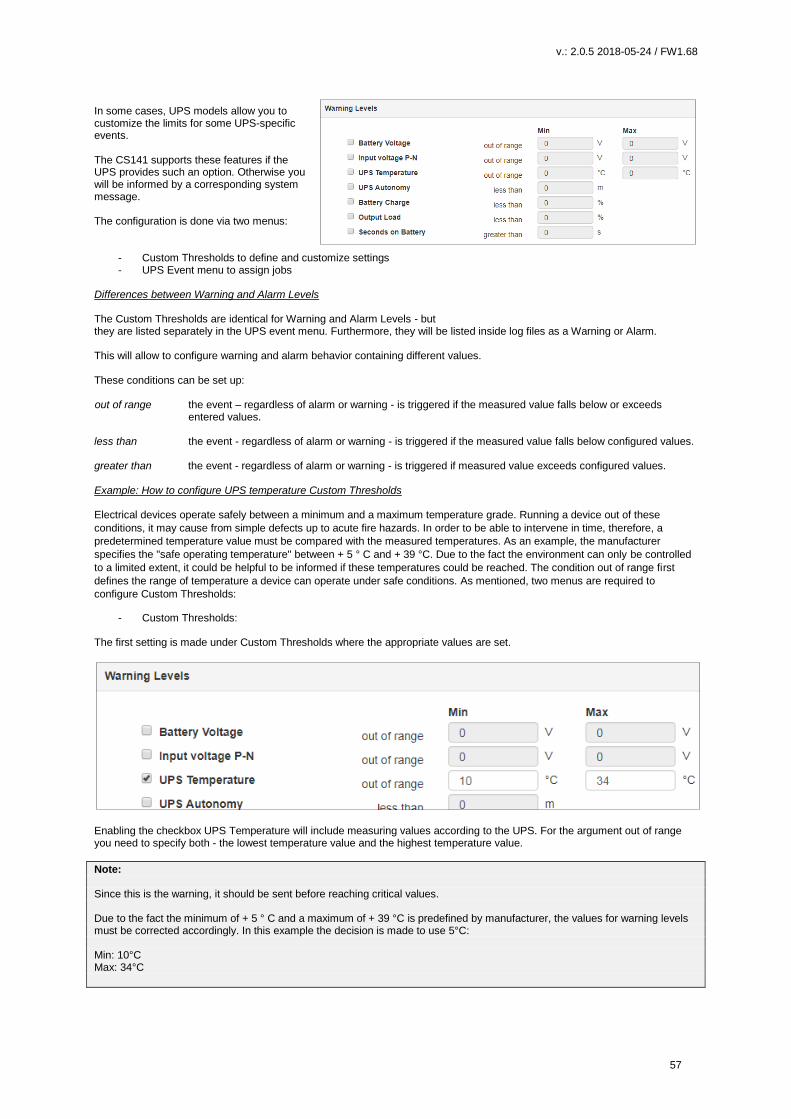
v.: 2.0.5 2018-05-24 / FW1.68
57
In some cases, UPS models allow you to customize the limits for some UPS-specific events. The CS141 supports these features if the UPS provides such an option. Otherwise you will be informed by a corresponding system message. The configuration is done via two menus:
- Custom Thresholds to define and customize settings - UPS Event menu to assign jobs
Differences between Warning and Alarm Levels The Custom Thresholds are identical for Warning and Alarm Levels - but they are listed separately in the UPS event menu. Furthermore, they will be listed inside log files as a Warning or Alarm. This will allow to configure warning and alarm behavior containing different values. These conditions can be set up: out of range the event – regardless of alarm or warning - is triggered if the measured value falls below or exceeds
entered values. less than the event - regardless of alarm or warning - is triggered if the measured value falls below configured values. greater than the event - regardless of alarm or warning - is triggered if measured value exceeds configured values. Example: How to configure UPS temperature Custom Thresholds Electrical devices operate safely between a minimum and a maximum temperature grade. Running a device out of these
conditions, it may cause from simple defects up to acute fire hazards. In order to be able to intervene in time, therefore, a
predetermined temperature value must be compared with the measured temperatures. As an example, the manufacturer
specifies the "safe operating temperature" between + 5 ° C and + 39 °C. Due to the fact the environment can only be controlled
to a limited extent, it could be helpful to be informed if these temperatures could be reached. The condition out of range first
defines the range of temperature a device can operate under safe conditions. As mentioned, two menus are required to
configure Custom Thresholds:
- Custom Thresholds: The first setting is made under Custom Thresholds where the appropriate values are set.
Enabling the checkbox UPS Temperature will include measuring values according to the UPS. For the argument out of range you need to specify both - the lowest temperature value and the highest temperature value.
Note: Since this is the warning, it should be sent before reaching critical values. Due to the fact the minimum of + 5 ° C and a maximum of + 39 °C is predefined by manufacturer, the values for warning levels must be corrected accordingly. In this example the decision is made to use 5°C: Min: 10°C Max: 34°C
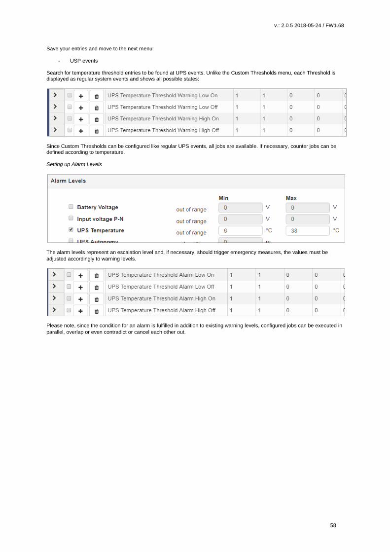
v.: 2.0.5 2018-05-24 / FW1.68
58
Save your entries and move to the next menu:
- USP events Search for temperature threshold entries to be found at UPS events. Unlike the Custom Thresholds menu, each Threshold is displayed as regular system events and shows all possible states:
Since Custom Thresholds can be configured like regular UPS events, all jobs are available. If necessary, counter jobs can be defined according to temperature. Setting up Alarm Levels
The alarm levels represent an escalation level and, if necessary, should trigger emergency measures, the values must be
adjusted accordingly to warning levels.
Please note, since the condition for an alarm is fulfilled in addition to existing warning levels, configured jobs can be executed in
parallel, overlap or even contradict or cancel each other out.
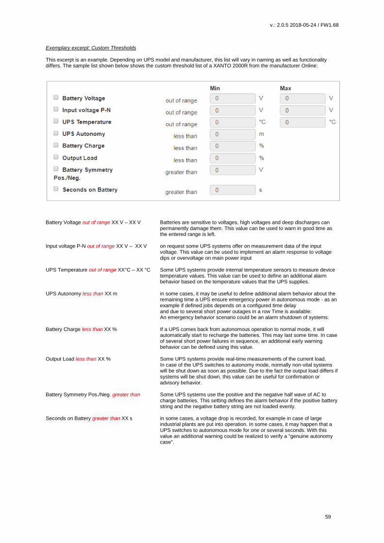
v.: 2.0.5 2018-05-24 / FW1.68
59
Exemplary excerpt: Custom Thresholds This excerpt is an example. Depending on UPS model and manufacturer, this list will vary in naming as well as functionality differs. The sample list shown below shows the custom threshold list of a XANTO 2000R from the manufacturer Online:
Battery Voltage out of range XX V – XX V Batteries are sensitive to voltages, high voltages and deep discharges can
permanently damage them. This value can be used to warn in good time as the entered range is left.
Input voltage P-N out of range XX V – XX V on request some UPS systems offer on measurement data of the input
voltage. This value can be used to implement an alarm response to voltage dips or overvoltage on main power input
UPS Temperature out of range XX°C – XX °C Some UPS systems provide internal temperature sensors to measure device
temperature values. This value can be used to define an additional alarm behavior based on the temperature values that the UPS supplies.
UPS Autonomy less than XX m in some cases, it may be useful to define additional alarm behavior about the
remaining time a UPS ensure emergency power in autonomous mode - as an example if defined jobs depends on a configured time delay and due to several short power outages in a row Time is available: An emergency behavior scenario could be an alarm shutdown of systems.
Battery Charge less than XX % If a UPS comes back from autonomous operation to normal mode, it will
automatically start to recharge the batteries. This may last some time. In case of several short power failures in sequence, an additional early warning behavior can be defined using this value.
Output Load less than XX % Some UPS systems provide real-time measurements of the current load.
In case of the UPS switches to autonomy mode, normally non-vital systems will be shut down as soon as possible. Due to the fact the output load differs if systems will be shut down, this value can be useful for confirmation or advisory behavior.
Battery Symmetry Pos./Neg. greater than Some UPS systems use the positive and the negative half wave of AC to
charge batteries. This setting defines the alarm behavior if the positive battery string and the negative battery string are not loaded evenly.
Seconds on Battery greater than XX s in some cases, a voltage drop is recorded, for example in case of large
industrial plants are put into operation. In some cases, it may happen that a UPS switches to autonomous mode for one or several seconds. With this value an additional warning could be realized to verify a "genuine autonomy case".
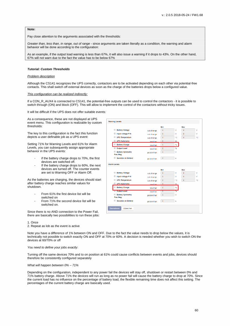
v.: 2.0.5 2018-05-24 / FW1.68
60
Note: Pay close attention to the arguments associated with the thresholds: Greater than, less than, in range, out of range - since arguments are taken literally as a condition, the warning and alarm behavior will be done according to the configuration: As an example, if the output load warning is less than 67%, it will also issue a warning if it drops to 43%. On the other hand, 67% will not warn due to the fact the value has to be below 67%
Tutorial: Custom Thresholds Problem description Although the CS141 recognizes the UPS correctly, contactors are to be activated depending on each other via potential-free contacts. This shall switch off external devices as soon as the charge of the batteries drops below a configured value. This configuration can be realized indirectly: If a CON_R_AUX4 is connected to CS141, the potential-free outputs can be used to control the contactors - it is possible to switch through (ON) and block (OFF). This will allow to implement the control of the contactors without tricky issues. It will be difficult if the UPS does not offer suitable events: As a consequence, these are not displayed at UPS event menu. This configuration is realizable by custom thresholds: The key to this configuration is the fact this function depicts a user definable job as a UPS event: Setting 71% for Warning Levels and 61% for Alarm Levels, you can subsequently assign appropriate behavior in the UPS events:
- if the battery charge drops to 70%, the first devices are switched off.
- If the battery charge drops to 60%, the next devices are turned off. The counter events are set to Warning OFF or Alarm Off.
As the batteries are charging, the devices should start after battery charge reaches similar values for shutdown.
- From 61% the first device list will be switched on
- From 71% the second device list will be switched on.
Since there is no AND connection to the Power Fail, there are basically two possibilities to run these jobs: 1. Once 2. Repeat as lob as the event is active Note you have a difference of 1% between ON and OFF. Due to the fact the value needs to drop below the values, it is technically not possible to switch exactly ON and OFF at 70% or 60%. A decision is needed whether you wish to switch ON the devices at 60/70% or off You need to define your jobs exactly: Turning off the same devices 70% and to on position at 61% could cause conflicts between events and jobs, devices should therefore be consistently configured separately What will happen between 0% – 71% Depending on the configuration, independent to any power fail the devices will stay off, shutdown or restart between 0% and 71% battery charge. Above 71% the devices will run as long as no power fail will cause the battery charge to drop at 70%. Since the current load has no influence on the percentage of battery load, the flexible remaining time does not affect this setting. The percentages of the current battery charge are basically used.

v.: 2.0.5 2018-05-24 / FW1.68
61
Note: A detailed description of the CON_R_AUX4 can be found at chapter Sensors
RCCMD
Ever heard something about RCCMD?
RCCMD (Remote Console Command) is the world's most successful shutdown solution for heterogeneous networks and is the best method to ensure initiating multiple messages and shutdown sequences. The solution integrates even the UPS to set up an all-in-one monitoring and messaging solution: The RCCMD clients listen on port 6003 for incoming messages of RCCMD server module. This module is a general part of - UPSMAN software - CS121 - CS141 - RCCMD licensed UPS manager. An RCCMD server controls the RCCMD clients inside networks. The functional scope ranges from monitoring, notifications up to a structured shutdown of a multiple server environment. RCCMD even considers mutual dependencies.
Note:
The RCCMD client is not freeware
A separate license is available and can be obtained worldwide from licensed resellers, OEM partners or directly ordered at
www.generex.de.
The license itself is unlimited valid, the service scope includes 2 years of free updates from the date of purchase.
Available RCCMD commands fort he CS141
As mentioned, CS141 provides an RCCMD server.
The RCCMD commands are defined as jobs via the system
events. There are four different categories available:
RCCMD Shutdown
The RCCMD shutdown sends a signal to an RCCMD client.
The RCCMD client advice the server to initiate the
shutdown sequence.
RCCMD Message
An RCCMD message is a notification text that can be sent
to an RCCMD receiver. This text will be displayed on the
screen using a separate message box.
RCCMD Execute
If scripts have to be executed in advance for a shutdown,
they can be triggered by using the execute command.
RCCMD offers not only ready-made commands but also the
possibility to start own scripts.
RCCMD Trap
Trap messages are pure informational messages that can
be sent to RCCMD clients. The client receives these text
messages and displays them inside a pop-up message box.
Note:
An initiated RCCMD shutdown cannot be withdrawn. However, within the RCCMD client, you can also define so-called
redundancies and limit IP addresses that are authorized to send an RCCMD signals. By doing so, as an example, two UPSs
need to advice a server shutdown. In this case the RCCMD execute wakeup will withdraw a server shutdown command.
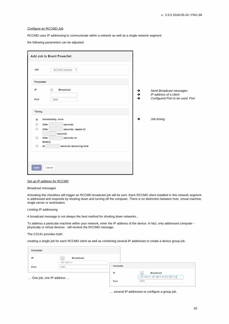
v.: 2.0.5 2018-05-24 / FW1.68
62
Configure an RCCMD-Job
RCCMD uses IP addressing to communicate within a network as well as a single network segment.
the following parameters can be adjusted:
Send Broadcast messages
IP address of a client
Configured Port to be used. Port
Job timing
Set up IP address for RCCMD
Broadcast messages
Activating this checkbox will trigger an RCCMD broadcast job will be sent. Each RCCMD client installed in this network segment
is addressed and responds by shutting down and turning off the computer. There is no distinction between host, virtual machine,
single server or workstation.
Limiting IP addressing
A broadcast message is not always the best method for shutting down networks...
To address a particular machine within your network, enter the IP address of the device. In fact, only addressed computer -
physically or virtual devices - will receive the RCCMD message.
The CS141 provides both:
creating a single job for each RCCMD client as well as combining several IP addresses to create a device group job.
… One job, one IP address …
… several IP-addresses to configure a group job.

v.: 2.0.5 2018-05-24 / FW1.68
63
For several IP addresses, please ensure the correct syntax:
192.168.3.1,192.168.3.18, ...
The IP addresses will be written without space between the individual entries. Otherwise you will receive a corresponding error
message.
Note:
Broadcast messages and individual IP addressed or collective addressed messages are mutually exclusive: You can configure
the RCCMD client to accept commands by single IP addresses. But the client cannot be configured to differ between a
broadcast message and a single message. If you want to shut down devices and device groups first and then send a broadcast,
you need to create several jobs with a corresponding time delay.
Port selection
As a default port, RCCMD uses port 6003. The
RCCMD client is listening on this port for a valid
RCCMD command.
If your RCCMD client has been assigned a
different port during installation and
configuration, ensure sender and receiver are
using the same ports.
RCCMD Job Timing The CS141 provides many system events a job can be assigned to. Some jobs allow to configure advanced timing:
Immediately, once As soon as an event happens, this job is executed at once and not repeated. After XXX seconds: The CS141 will wait a pre-defined time in seconds and than exucte the jobIf the event is
no longer active before time is up, the job will not be executed. Repeat all XXX seconds: The job is repeated cyclically until the event no longer is no longer active. After XXX seconds on battery: The event forces the UPS will to switch to autonomous mode.The job will be executed if
the UPS remains a pre-defined time in this state. For example, if 300 seconds are set, this job will only be executed if the UPS operates in autonomous reaches 300 seconds.
At XXX seconds remaining time: The job is executed when the remaining UPS operating time is reached or undershot.
Note based on the current load this time value becomes flexible
RCCMD command
Der RCCMD Shutdown
The RCCMD shutdown is predefined and advices the addressed RCCMD client to shut down the operating system and turn off
the device. Adjustable options include broadcast, sending to individual IP addresses and the port used for RCCMD.

v.: 2.0.5 2018-05-24 / FW1.68
64
Die RCCMD Message
The RCCMD message is a text message that can be defined freely. The text box automatically shifts with the entered text as
soon as you reach the right margin. This message will then appear as an alert on a computer the RCCMD client is installed to.
RCCMD also displays a warning box on the taskbar.
RCCMD Executes
An extensive feature within RCCMD is the possibility to run own executables and batch files on a target computer.
This function is useful if scripts have to be executed right before a shutdown is triggered. It is necessary to move the file to be
executed to the installation directory of the RCCMD client. Afterwards, the CS141 provides to execute this script directly.
Note: The screenshot shows the command helloworld.bat has been entered. In this case, the RCCMD client on the PC with the IP address 192.168.3.1 would try to start the file hallowelt.bat directly. If you want to use other directories, you need to specify them accordingly: C:\skript\helloworld.bat Please note, it is tricky to run a script on a PC that shall trigger scripts on a third device.
RCCMD Traps
RCCMD traps are data packets designed to inform about the current state of the UPS:
A data package is generated, which can be received, read out and interpreted by a corresponding software or device.
The following list contains possible variables that you can use to define RCCMD traps:
#AGENTSOFTREV CS141 Firmware Version #AUTONOMTIME Autonomiezeit in Minuten #BATT2OLD() Zeit in Monate bis zum Event „Please check batteries“ #BATT2OLD_YEARS Batteriealter Jahre #BATTCAP Batterie Kapazität in % #BATTINSTDATE Installationsdatum der Batterie #BATTTESTDATE Datum vom letzten Batterietest #BATTVOLT Batterie Spannung in V #CHARGECURR aktueller Ladestrom #CNT_BL Counter Battery Low #CNT_PF Counter Powerfail #CNT_SA Counter Active Shutdowns #CNT_SD Counter Shutdowns #CNT_TF Counter Testfehler #DATE aktuelles Datum #EVENTSTATE obstatus (idle, error, progress, success) #FULLTESTDATE Datum des letzten Fulltests #GETLASTRESULT() Ergebnisse vom letzten durchgeführten Test #HOLDTIME Laufzeit bei 100 Prozent Last #IDENT_NAME Name des SNMP Adapters #INCURR0/1/2 Eingangsstrom in V #INFREQ0/1/2 Eingangsfrequenz in Hz #INPHASES Anzahl Eingangsphasen #INPUTCURRENT0/1/2 aktuelle Eingangsstrom in V
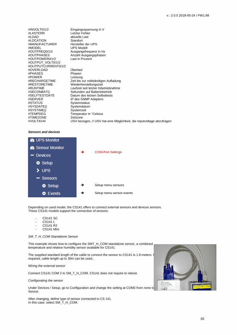
v.: 2.0.5 2018-05-24 / FW1.68
65
#INVOLT0/1/2 Eingangsspannung in V #LASTERR Letzter Fehler #LOAD aktuelle Last #LOCATION Standort #MANUFACTURER Hersteller der UPS #MODEL UPS Modell #OUTFREQ0/1/2 Ausgangsfrequenz in Hz #OUTPHASES Anzahl Ausgangsphasen #OUTPOWER0/1/2 Last in Prozent #OUTPUT_VOLT0/1/2 #OUTPUTCURRENT0/1/2 #OVERLOAD Überlast #PHASES Phasen #POWER Leistung #RECHARGETIME Zeit bis zur vollständigen Aufladung #RESTORETIME Wiederherstellungszeit #RUNTIME Laufzeit seit letzter Inbetriebnahme #SECONBAT() Sekunden auf Batteriebetrieb #SELFTESTDATE Datum des letzten Selbsttests #SERVER IP des SNMP Adapters #STATUS Systemstatus #SYSDATE() Systemdatum #SYSTIME() Systemzeit #TEMPDEG Temperatur in °Celsius #TIMEZONE Zeitzone #VOLTAVAI USV bezogen, // USV hat eine Möglichkeit, die Inputvoltage abzufragen
Sensors and devices
COM-Port Settings Setup menu sensors
Setup menu sensor events
Depending on used model, the CS141 offers to connect external sensors and devices sensors. These CS141 models support the connection of sensors:
- CS141 SC - CS141 L - CS141 R2 - CS141 Mini
SM_T_H_COM Standalone Sensor This example shows how to configure the SMT_H_COM standalone sensor, a combined temperature and relative humidity sensor available for CS141. The supplied standard length of the cable to connect the sensor to CS141 is 1.8 meters. If required, cable length up to 30m can be used.. Wiring the external sensor Connect CS141 COM 2 to SM_T_H_COM. CS141 does not require to reboot. Configurating the sensor Under Devices / Setup, go to Configuration and change the setting at COM2 from none to Sensor. After changing, define type of sensor connected to CS 141. In this case: select SM_T_H_COM.

v.: 2.0.5 2018-05-24 / FW1.68
66
Press Apply to start the corresponding service. The status bar indicates the process.
Setting up the sensor
COM-Port Settings Setup menu sensors
Setup menu sensor events
Depending on the sensor the configuration options will differ. The SM_T_H_COM offers the following configuration options: Description and location data
Under Location, enter the function of the sensor or a unique name. This designation displays the sensor in the sensor monitor.
Thresholds Low / High To define a general alarm behavior, the CS141 requires information about critical values. For the combined temperature / humidity sensor, the temperature scale includes a value of -25 ° C to + 100 ° C and a humidity scale of 0 to 100%
Offset - Settings
Although the SM_T_H_COM is a calibrated ready-to-use sensor,
the operating environment may require to adjust the settings.
The values to correct environmental differences will be defined via
the offset settings. The entered values are subtracted or added
from the measured value before using

v.: 2.0.5 2018-05-24 / FW1.68
67
Sensormonitor: Check the settings
Monitoring of sensors connected to CS141
Once completed all settings, the sensor data will be shown at Sensor Monitor:
The yellow line represents the value of the Threshold (low). The upper line represents the Threshold (high). As soon as the value exceeds or falls below these lines, the color changes to red and a corresponding job can be triggered for the according sensor event.
Event handling according to sensors
COM-Port Settings Setup menu sensors
Setup menu sensor events
Sensor-related system events The CS141 provides defining system jobs via connected sensors. The available system events refer to the measured values of the connected sensors. The following events are available for SM_T_H_COM. SM_T_H_COM Temperature High The value at Threshold (high) defines the upper critical temperature limit. If this temperature is exceeded, a corresponding alarm behavior can be triggered. SM_T_H_COM Temperature Low The value Threshold (low) defines the lower critical temperature limit. If this temperature is undershot, a corresponding alarm behavior can be triggered.

v.: 2.0.5 2018-05-24 / FW1.68
68
SM_T_H_COM Temperature Normal Defined by the values for the upper and lower temperature limits. If no limits are entered, any displayed temperature will be displayed as "normal. SM_T_H_COM Humidity High The value is defined by Threshold (high) for the relative humidity and determines the upper critical limit for humidity. If this value is exceeded, a corresponding alarm behavior can be triggered. SM_T_H_COM Humidity Low The value is defined via Threshold (low) for the relative humidity and determines the lower critical limit for humidity. If this value is undershot, a corresponding alarm behavior can be triggered. SM_T_H_COM Humidity Normal Defined by the values for the upper and lower relative humidity. If no limits are entered, any displayed humidity will be displayed as "normal". SM_T_H_COM Connection Lost If the connection between the CS141 and the SM_T_H_COM tears off, a corresponding alarm behavior can be triggered via this system event. SM_T_H_COM Connection Restored The counter event to Connection Lost: The connection has been restored, a corresponding alarm behavior can be triggered via this system event.
Defining a Job for sensor events
Note: In order to allow a full integration of the environmental control sensors into the warning and alarm behavior, the jobs are the same as those that can be triggered during UPS events. Please note that other sensors may provide different setup options according to their function.
The symbols used in this menu are described in detail in chapter setting up system events.
Click > to open the job list and get a detailed overview;
Für das Ereignis einer zu hohen Temperatur ist demnach bereits ein Job konfiguriert. Feel free to add as many jobs as you wish…
Sensormanager
If you need more than one sensor, the CS141 offers the possibility to operate up to 8 environmental control sensors connected to an external device called sensor manager. The SENSORMANAGER is not an independent device. In principle it is comparable to an intelligent HUB. Through this device, additional sensors and access control systems can be directly controlled by the CS141. In conjunction with the separately available SM_CON adapter, both analog and digital systems from a wide variety of manufacturers can be connected to the CS141.The SENSOR MANAGER thus forms an optional extension to adapt the application options of the CS141 to numerous scenarios inside a building management concept.
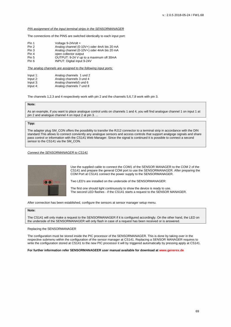
v.: 2.0.5 2018-05-24 / FW1.68
69
PIN assignment of the input terminal strips in the SENSORMANAGER The connections of the PINS are switched identically to each input port: Pin 1 Voltage 9-24Volt + Pin 2 Analog channel (0-10V+) oder 4mA bis 20 mA Pin 3 Analog channel (0-10V+) oder 4mA bis 20 mA Pin 4 open collector output Pin 5 OUTPUT: 9-24 V up to a maximum ofl 30mA Pin 6 INPUT: Digital input 9-24V The analog channels are assigned to the following input ports: Input 1: Analog channels 1 und 2 Input 2: Analog channels 3 und 4 Input 3: Analog channels5 und 6 Input 4: Analog channels 7 und 8
The channels 1,2,3 and 4 respectively work with pin 2 and the channels 5,6,7,8 work with pin 3.
Note: As an example, if you want to place analogue control units on channels 1 and 4, you will find analogue channel 1 on input 1 at pin 2 and analogue channel 4 on input 2 at pin 3. ...
Tipp: The adapter plug SM_CON offers the possibility to transfer the RJ12 connector to a terminal strip in accordance with the DIN standard.This allows to connect conviently any analogue sensors and access controls that support analgoge signals and share pass control or information with the CS141 Web Manager. Since the signal is continued it is possible to connect a second sensor to the CS141 via the SM_CON.
Connect the SENSORMANAGER to CS141
Use the supplied cable to connect the COM1 of the SENSOR MANAGER to the COM 2 of the CS141 and prepare the general COM port to use the SENSORMANAGER. After preparing the COM Port at CS141 connect the power supply to the SENSORMANAGER. Two LED's are installed on the underside of the SENSORMANAGER: The first one should light continuously to show the device is ready to use. The second LED flashes - if the CS141 starts a request to the SENSOR MANAGER.
After connection has been established, configure the sensors at sensor manager setup menu.
Note: The CS141 will only make a request to the SENSORMANAGER if it is configured accordingly. On the other hand, the LED on the underside of the SENSORMANAGER will only flash in case of a request has been received or is answered.
Replacing the SENSORMANAGER The configuration must be stored inside the PIC processor of the SENSORMANAGER. This is done by taking over in the respective submenu within the configuration of the sensor manager at CS141. Replacing a SENSOR MANAGER requires to write the configuration stored at CS141 to the new PIC processor it will by triggered automatically by pressing apply at CS141. For further information refer SENSORMANAGEER user manual available for download at www.generex.de

v.: 2.0.5 2018-05-24 / FW1.68
70
Buzzer
The CS141_BUZ is an acoustic alarm to be used with the CS141 SNMP adapter (CS141 SC or CS141 L). The CS141_BUZ is
based on a piezo element using an internal power supply. Due to this fact, no separate power supply is required. The volume is
about 85 db. The CS121_BUZ provides an RJ12 to be directly connected to CS141. Furthermore, an RJ12 socket for the output
of PINs 1, 2, 3 to use external devices.
In addition, the acoustic signal of the buzzer can be remotely reset by closing a potential-free contact via the two-poled contact
terminal block. Furthermore, a LED indicates a manually switched off alarm. This LED will stay blinking until it will be triggered
by CS141 to normal state.
Technical data:
voltage usage: 12 – 15 VDC
power usage: ca. 30mA
Volume: ca. 85 dB
Connection type: wired, RJ12, 6_5, 5_m
Dimensions: 70 x 70 x 40 mm
Connect to CS141:
Use enclosed cable to connect the buzzer CS141_BUZ to AUX Port of CS141.
Configure the buzzer:
Step: 1
Under Devices/Setup, select Buzzer at COM and press Apply.

v.: 2.0.5 2018-05-24 / FW1.68
71
Step 2
Under Devices you find the buzzer alarm menu:
Apply transfers the current setting to the system configuration. Selected functions will be displayed at the BUZZER MONITOR.
Furthermore, in the upper status bar the buzzer will be shown as operational.
Step 3:
Select an event the buzzer shall toggle – as an example buzzer alarm if recognizes a power fail
Press + to open job configuration dialog:
Under Job select Buzzer:
Relays on
Additionally, the buzzer provides a relay for external
connections to be switched.
Buzzer on
In case of a power fail the buzzer will be triggered. As soon
as main power returned back, the event "Power restored"
needs a job to switch off buzzer.

v.: 2.0.5 2018-05-24 / FW1.68
72
Events according to a buzzer
Search for the buzzer event menu:
At BUZZER ON click + to start job the configuration dialog
Choose the job to be executed, because the buzzer was triggered.
Depending on your setting, a corresponding action will be triggered in
addition to the triggered buzzer and simultaneously noted in the event
log.
Note: You can define structured job chains by different devices connected to the CS141: Therefore it is possible to select the BUZZER from inside the AUX menu and trigger it triggered accordingly. In that case, the AUX event handling will trigger the buzzer and then the next event.
On the other hand, events can be executed from any device via the buzzer: Therefore, it is possible to send an SMS because the buzzer has switched on the relay.
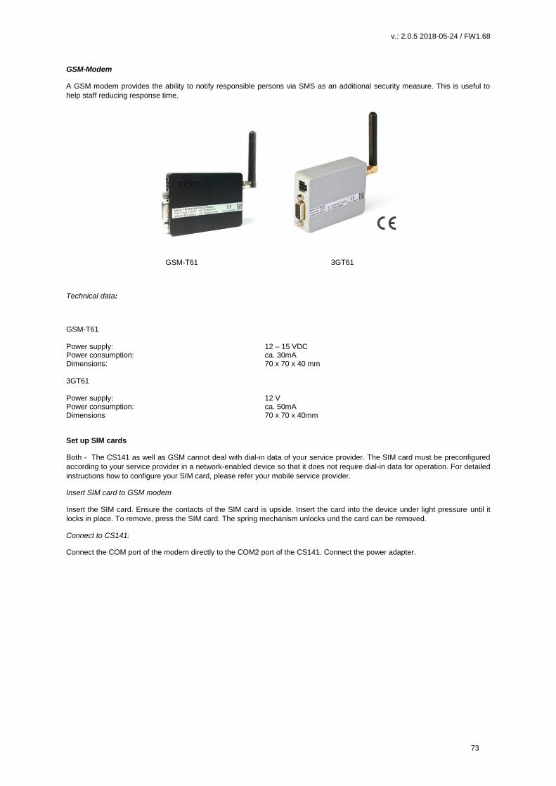
v.: 2.0.5 2018-05-24 / FW1.68
73
GSM-Modem
A GSM modem provides the ability to notify responsible persons via SMS as an additional security measure. This is useful to
help staff reducing response time.
GSM-T61 3GT61
Technical data:
GSM-T61 Power supply: 12 – 15 VDC Power consumption: ca. 30mA Dimensions: 70 x 70 x 40 mm 3GT61 Power supply: 12 V Power consumption: ca. 50mA Dimensions 70 x 70 x 40mm
Set up SIM cards
Both - The CS141 as well as GSM cannot deal with dial-in data of your service provider. The SIM card must be preconfigured
according to your service provider in a network-enabled device so that it does not require dial-in data for operation. For detailed
instructions how to configure your SIM card, please refer your mobile service provider.
Insert SIM card to GSM modem
Insert the SIM card. Ensure the contacts of the SIM card is upside. Insert the card into the device under light pressure until it
locks in place. To remove, press the SIM card. The spring mechanism unlocks und the card can be removed.
Connect to CS141:
Connect the COM port of the modem directly to the COM2 port of the CS141. Connect the power adapter.

v.: 2.0.5 2018-05-24 / FW1.68
74
Configuring GSM modem
Step: 1
At Devices/setup choose GSM modem.
Press apply to start the services that are required to use the GSM modem.
Step 2 Under devices, open GSM modem configuration menu. The CS141 provides two different types of connection: Serial connection
For the serial connection via COM1 select Mode: com. Please note, changes to baud rate, parity and stop bit are usually not necessary.
Apply saves the current setting to the system configuration and restarts the GSM modem service. The upper status bar indicates the GSM modem is ready for operation.
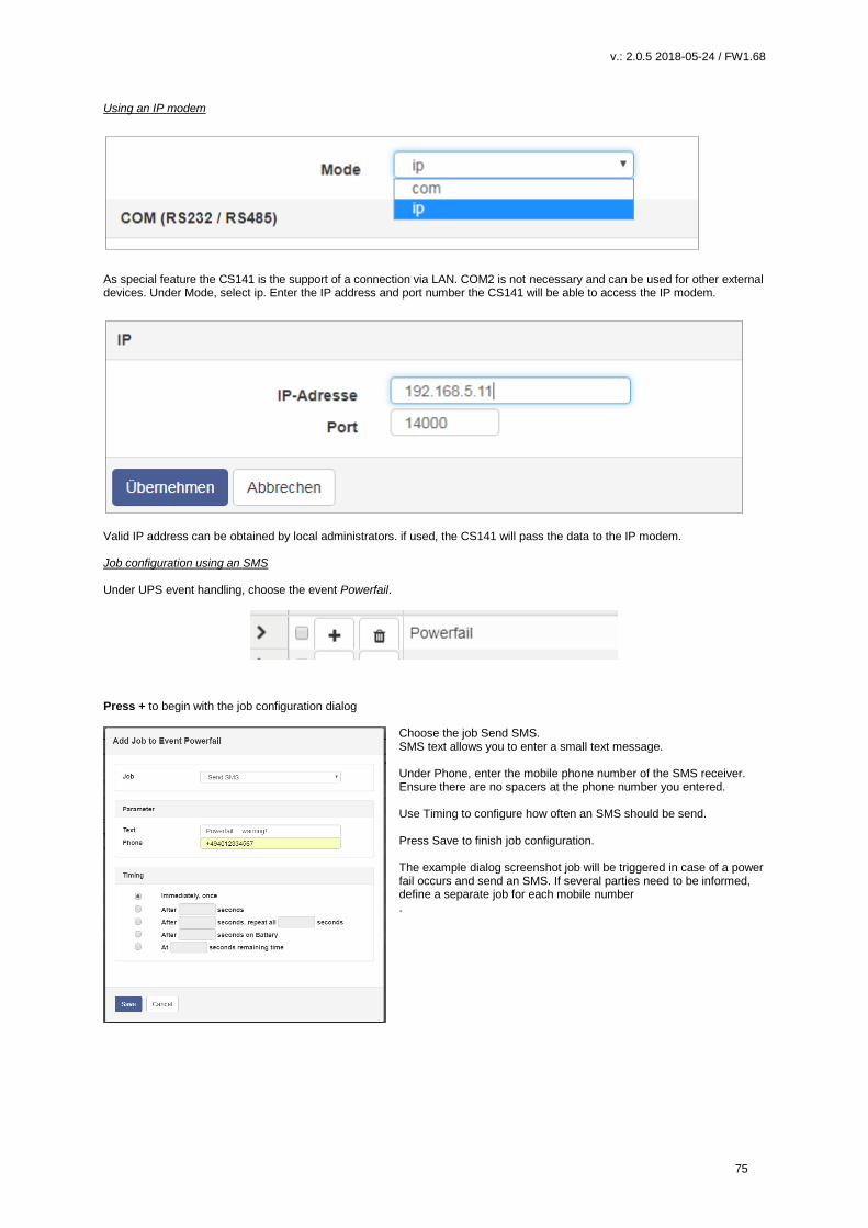
v.: 2.0.5 2018-05-24 / FW1.68
75
Using an IP modem
As special feature the CS141 is the support of a connection via LAN. COM2 is not necessary and can be used for other external devices. Under Mode, select ip. Enter the IP address and port number the CS141 will be able to access the IP modem.
Valid IP address can be obtained by local administrators. if used, the CS141 will pass the data to the IP modem. Job configuration using an SMS Under UPS event handling, choose the event Powerfail.
Press + to begin with the job configuration dialog
Choose the job Send SMS. SMS text allows you to enter a small text message. Under Phone, enter the mobile phone number of the SMS receiver. Ensure there are no spacers at the phone number you entered. Use Timing to configure how often an SMS should be send. Press Save to finish job configuration. The example dialog screenshot job will be triggered in case of a power fail occurs and send an SMS. If several parties need to be informed, define a separate job for each mobile number .

v.: 2.0.5 2018-05-24 / FW1.68
76
CON_AUX4 und CON_R_AUX4
There is more than one method to communicate with parent and child systems: The
external devices CON_AUX4 and CON_R_AUX4 provide input as well as outputs to
get information as well controlling third-party devices:
To start configuration, define COM3 as AUX port. Type will be used to toggle
between CON_AUX4 and CON_R_AUX4.
Configuration
Once the AUX service has been started, the general operability is displayed accordingly in the upper bar. Please wait until the
service is ready to use before accessing the configuration menu - it will appear automatically as a sub menu at Devices.
Depending on whether a CON_AUX4 or CON_R_AUX4 has been connected, the configuration screen will differ:
Figure 1: Configuration menu – CON_AUX4
Figure 2: Configuration menu – CON_R_AUX4 Port
1: Port
Current port number
2 Name
Since the cable of the target device can be up to 60 meters, define a name or location. The field Name is freely editable.
3 Output
The ports can be configured as an output to switch potential-free contacts. This function is only available at CON_R_AUX4.
5 NC normally closed
Determine if the input / output normally contains an open or closed contact. Among other things, this function defines the alarm
behavior
Switch on cs141 Powerup
The port is automatically switched on if the CS141 is starts or after reboot.
7 Power up delay
During CS141 boots, the port will be turned on after predefined seconds. This allows a time-delayed startup or switching through
potential-free contacts during a restart.
8 Apply / Cancel
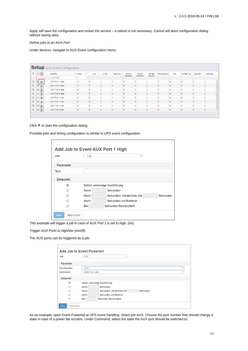
v.: 2.0.5 2018-05-24 / FW1.68
77
Apply will save the configuration and restart the service – a reboot is not necessary. Cancel will abort configuration dialog
without saving data.
Define jobs to an AUX-Port
Under devices, navigate to AUX Event configuration menu:
Click + to start the configuration dialog.
Possible jobs and timing configuration is similar to UPS event configuration
This example will trigger a job in case of AUX Port 1 is set to high. (on)
Trigger AUX Ports to high/low (on/off):
The AUX ports can be triggered as a job:
As an example, open Event Powerfail at UPS event handling. Select job AUX. Choose the port number that should change a
state in case of a power fail occuers. Under Command, select the state the AUX port should be switched to.
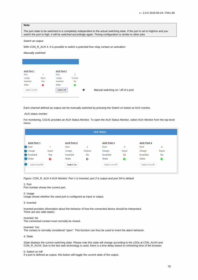
v.: 2.0.5 2018-05-24 / FW1.68
78
Note:
The port state to be switched to is completely independent to the actual switching state. If the port is set to high/on and you
switch the port to high, it will be switched accordingly again. Timing configuration is similar to other jobs
Switch an output
With CON_R_AUX 4, it is possible to switch a potential-free relay contact on activation:
Manually switched
Manual switching on / off of a port
Each channel defined as output can be manually switched by pressing the Switch on button at AUX monitor.
AUX status monitor
For monitoring, CS141 provides an AUX Status Monitor. To open the AUX Status Monitor, select AUX Monitor from the top-level
menu:
Figure: CON_R_AUX 4 AUX Monitor: Port 1 is inverted, port 2 is output and port 3/4 is default
1: Port Port number shows the current port. 2: Usage Usage shows whether the used port is configured as input or output. 3: Inverted Inverted provides information about the behavior of how the connected device should be interpreted. There are two valid states: Inverted: No The connected contact must normally be closed. Inverted: Yes The contact is normally considered "open". This function can thus be used to invert the alarm behavior. 4: State State displays the current switching state. Please note this state will change according to the LEDs at CON_AUX4 and CON_R_AUX4. Due to the fact web technology is used, there is a time delay based on refreshing time of the browser. 5: Switch on /off If a port is defined as output, this button will toggle the current state of the output.
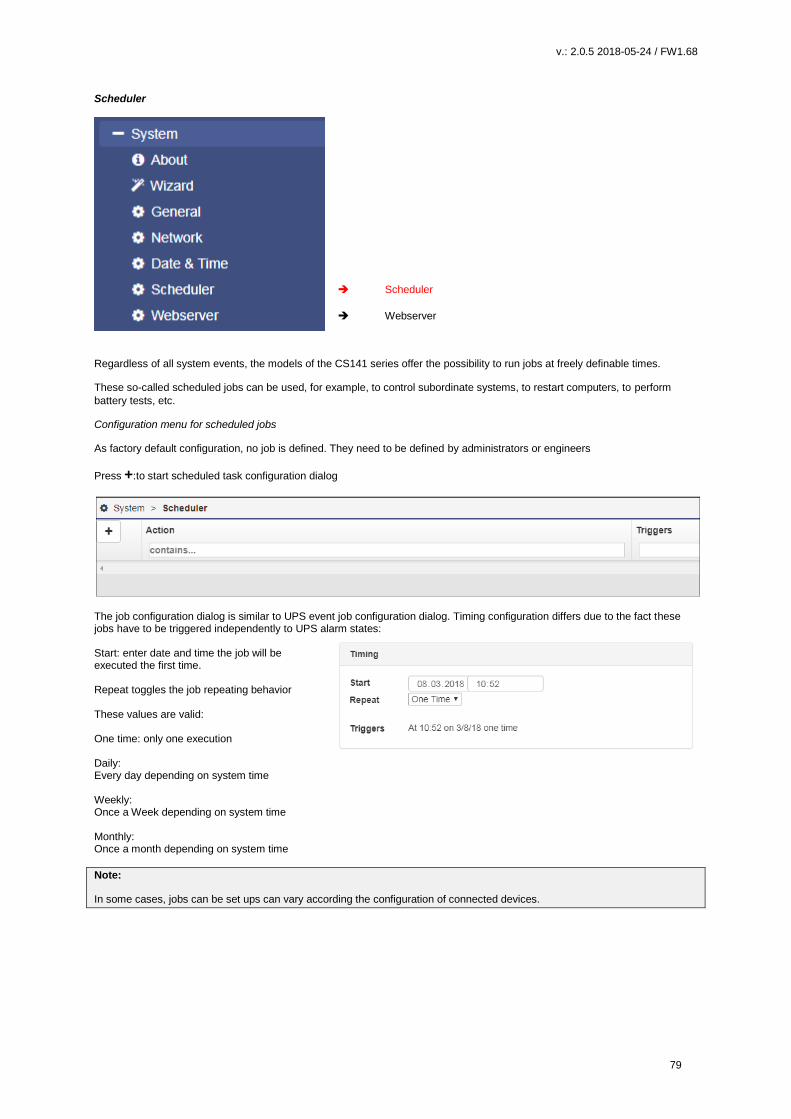
v.: 2.0.5 2018-05-24 / FW1.68
79
Scheduler
Scheduler
Webserver
Regardless of all system events, the models of the CS141 series offer the possibility to run jobs at freely definable times.
These so-called scheduled jobs can be used, for example, to control subordinate systems, to restart computers, to perform
battery tests, etc.
Configuration menu for scheduled jobs
As factory default configuration, no job is defined. They need to be defined by administrators or engineers
Press +:to start scheduled task configuration dialog
The job configuration dialog is similar to UPS event job configuration dialog. Timing configuration differs due to the fact these jobs have to be triggered independently to UPS alarm states: Start: enter date and time the job will be executed the first time. Repeat toggles the job repeating behavior These values are valid: One time: only one execution Daily: Every day depending on system time Weekly: Once a Week depending on system time Monthly: Once a month depending on system time
Note:
In some cases, jobs can be set ups can vary according the configuration of connected devices.
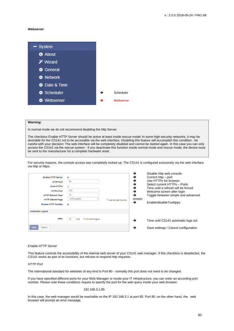
v.: 2.0.5 2018-05-24 / FW1.68
80
Webserver
Scheduler
Webserver
Warning: In normal mode we do not recommend disabling the http Server. The checkbox Enable HTTP Server should be active at least inside rescue mode! In some high-security networks, it may be desirable for the CS141 not to be accessible via the web interface. Disabling this feature will accomplish this condition - be careful with your decision: The web interface will be completely disabled and cannot be started again. In this case you can only access the CS141 via the rescue system - if you deactivate this function inside normal mode and rescue mode, the device must be sent to the manufacturer for a complete hardware reset.
For security reasons, the console access was completely locked up. The CS141 is configured exclusively via the web interface via http or https.
Disable http web console Current http – port Use HTTPs for browser Select current HTTPs – Ports Time until a refresh will be forced Welcome screen after login Toggle between simple and advanced screen Enable/disableTooltipps Time until CS141 automatic logs out Save settings / Cancel configuration
Enable HTTP Server This feature controls the accessibility of the internal web server of your CS141 web manager. If this checkbox is deselected, the CS141 works as part of its functions, but refuses to respond http requests. HTTP Port The international standard for websites of any kind is Port 80 - normally this port does not need to be changed. If you have specified different ports for your Web Manager or inside your IT infrastructure, you can enter an according port number. Please note these conditions require to specify the port for the web query inside your web browser: 192.168.3.1:85 In this case, the web manager would be reachable on the IP 192.168.3.1 at port 85. Port 80, on the other hand, the web browser will prompt an error message.

v.: 2.0.5 2018-05-24 / FW1.68
81

v.: 2.0.5 2018-05-24 / FW1.68
82
Force HTTPs A standard HTTP connection on the Internet can be easily tapped by unauthorized persons. In order to avoid this and thus ensure a secure data transfer, an HTTPs connection is used. This will allow encrypted data transmissions as well as authenticated server devices. As advantage the security level increases. As disadvantage reaction time will drop since the data are transmitted encrypted. Force HTTPs stops regular HTTP traffic and forces the use of HTTPs HTTPs Port As a standard HTTPs port 443 will be used. If necessary, you can adapt this port to your network.
Note: Once force https is enabled, the syntax https: // must be used. Otherwise there are two basic options for the web browser: Connection timeout Since CS141 only responds to HTTPS, the web browser will not receive data. Forwarding (browser-specific) If multiple CS141s works inside a network, it may happen that there is an alternative valid entry in your web browser - you will be re-routed to another CS141.
HTTP Refresh time The CS141 will automatically return an updated page showing, among other things, the status of UPS systems or other available status monitors. This value defines how often an automatic page refresh is performed. By default, the CS141 updates these displays every 10 seconds. Use simple monitor The CS141 provides two different monitoring screens for UPS data. This function is useful in case of a small monitor is used.
The simple monitor (pictured on the right) contains significantly less information but better readability Enable HTTP Tooltips Tooltips are contextual hint windows that pop up automatically when you hover settings. By default, the tooltips are enabled but can be permanently disabled.

v.: 2.0.5 2018-05-24 / FW1.68
83
Diagnosis: Status LED's
The CS141 offers several options for diagnosis. The fastest method is a quick visual inspection of the LEDs
To perform a quick inspection, take a look at the two LEDs in front of the CS141:
Green LED Red LED Adapter
OFF OFF No Power
OFF AN Boot in progress
OFF SLOW BLINKING Update in progress
AUS FAST BLINKING Update failure
ON ON Communication lost: UPS or external device
SLOW BLINKING OFF Everything is OK with the world
After logging in, the CS141 will display a more detailed overview of the current system state:
A green marker indicates communication without problems.
Please note the setting no UPS device selected will show a dummy screen and the LED will also be green.
A yellow marker is displayed if:
- - The device will initialize and the communication is being established
- - there is a warning behavior. It might be required appropriate intervention in the near future.
If the LED is red, an alarm or critical condition is currently detected:
- The CS141 has lost communication with a connected device
- There is a system critical condition, which requires a timely intervention.
The type of the alarm is displayed in detail.
A blue marker indicates that the device was probably configured correctly, but no initial communication has been established.
A gray marker and the description disabled means that a device has been completely deactivated and cannot provide any data.
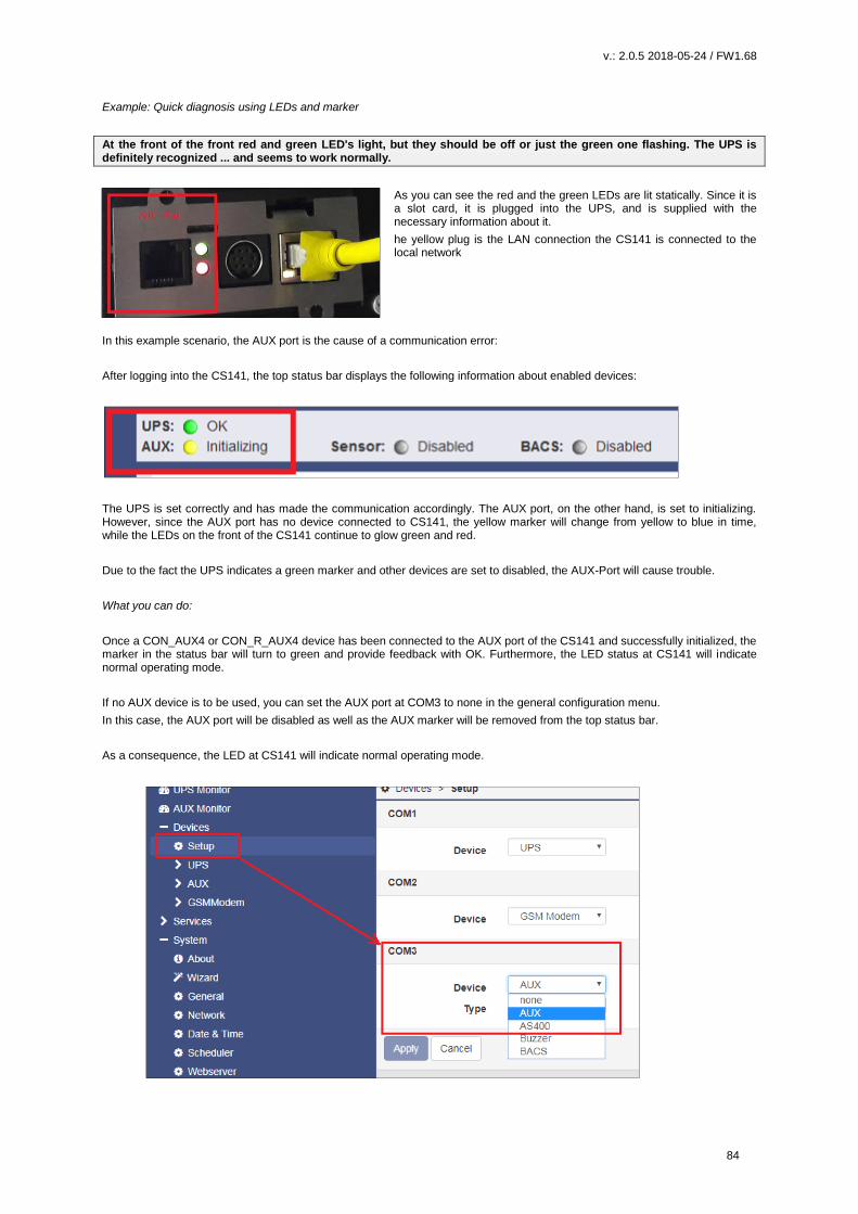
v.: 2.0.5 2018-05-24 / FW1.68
84
Example: Quick diagnosis using LEDs and marker
At the front of the front red and green LED's light, but they should be off or just the green one flashing. The UPS is definitely recognized ... and seems to work normally.
As you can see the red and the green LEDs are lit statically. Since it is a slot card, it is plugged into the UPS, and is supplied with the necessary information about it.
he yellow plug is the LAN connection the CS141 is connected to the local network
In this example scenario, the AUX port is the cause of a communication error:
After logging into the CS141, the top status bar displays the following information about enabled devices:
The UPS is set correctly and has made the communication accordingly. The AUX port, on the other hand, is set to initializing. However, since the AUX port has no device connected to CS141, the yellow marker will change from yellow to blue in time, while the LEDs on the front of the CS141 continue to glow green and red.
Due to the fact the UPS indicates a green marker and other devices are set to disabled, the AUX-Port will cause trouble.
What you can do:
Once a CON_AUX4 or CON_R_AUX4 device has been connected to the AUX port of the CS141 and successfully initialized, the marker in the status bar will turn to green and provide feedback with OK. Furthermore, the LED status at CS141 will indicate normal operating mode.
If no AUX device is to be used, you can set the AUX port at COM3 to none in the general configuration menu.
In this case, the AUX port will be disabled as well as the AUX marker will be removed from the top status bar.
As a consequence, the LED at CS141 will indicate normal operating mode.

v.: 2.0.5 2018-05-24 / FW1.68
85
Logfiles
Event Log
Event Log
Charge and discharge state data
Graphical data log diagram
The event log contains all actions concerning the CS141 and the UPS are recorded. The event history will be written by any
event containing a log job. The most significant jobs are included by default settings. Administrators are able to create, edit and
delete default settings as well as creating custom log entries.
After reboot the first entry is a message by CS141 with its OEM ID:
Please note the latest entry is always on top of the list. Download as CSV file creates a CSV file from this event log and stores it
locally on your hard disk:
Any program that can deal with CSV files can be used to open the event log.
In case of current memory to store event, logs are exhausted, the CS141 will open an archive file and move the current event
log. This archive file will be provided for both: downloading as well as instant view.

v.: 2.0.5 2018-05-24 / FW1.68
86
Note:
Depending on the configuration, the system events in the event log are kept for up to three months. As soon as the running
memory for the current event log file is exhausted, the files are stored alternately in up to two archive files. This generally
provides a monitored period of up to 9 months from initial startup.
Navigate between logfiles
By default, the current event log is displayed
Administrators are able to toggle between the two logs by clicking the button "Show
archived Logfiles" in the upper right corner.
By doing so, the label of this button will change:
To return to the active log file, press the button labeled "Show active log file"
Data Log
Event Log
Charge and discharge state data
Graphical data log diagram
The data log recognizes measurement data of the UPS. Due to the fact these are provided with a time stamp, they can be
combined with the event log:
Analysts can build event chains with additional UPS data.
Like the event log, data log can be exported as CSV file as data backup. The data log stores the entries every 3 minutes and
keeps the entries 8 weeks as the current data log file. After that the actual data log will be moved to an archive file and a new
data log for the current data is opened.
The CS141 provides storing up to 2 independent archive files:
In addition to the current period, there are up to 24 weeks available. After expiry of the time, the oldest archive file is replaced.
As with the event log, administrators can toggle between active log and achieved logfiles.

v.: 2.0.5 2018-05-24 / FW1.68
87
Data log Diagram
Event Log
Charge and discharge state data
Graphical data log diagram
With data log Chart CS141 provides a graphical presentation of the battery history:
This feature allows to examine all entries within the data log exclusively. Single entries can be selected by using checkboxes:
In addition to the current values, the CS141 provides selecting specific values from current databases.
As a default, all check marks are set when called. You can use the Unselect All Lines function to remove them and set the
relevant checkmarks.
How to use the calendar
The calendar feature provides a quick
overview of existing time periods that
are selectable. Click the date field to
bring up the calendar:
The dates of the corresponding period
are automatically loaded and
displayed inside the main window.
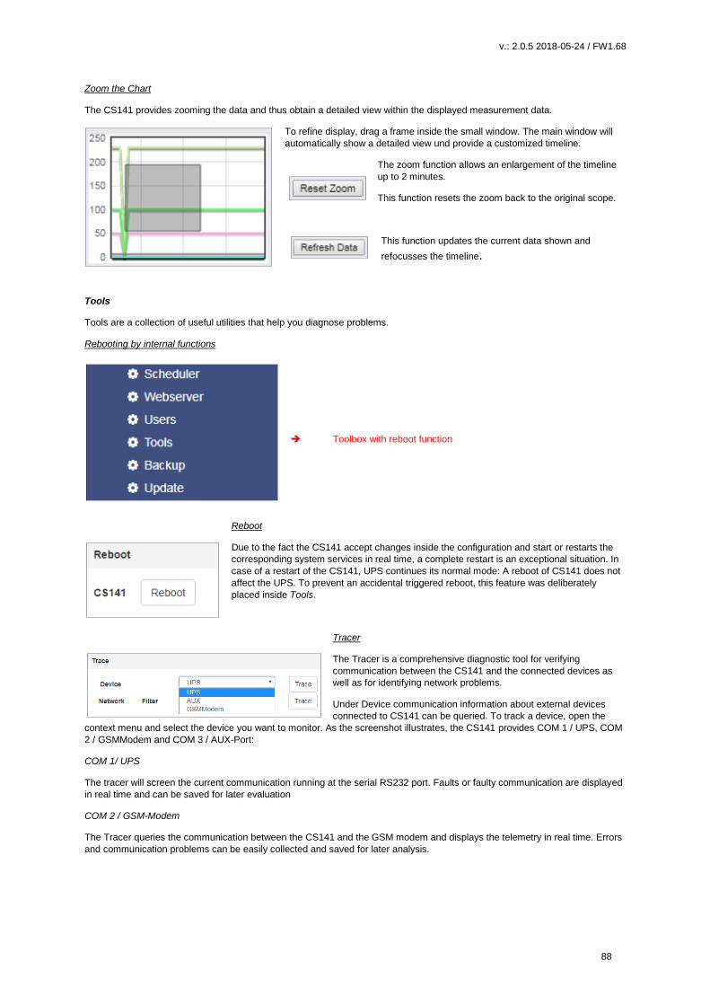
v.: 2.0.5 2018-05-24 / FW1.68
88
Zoom the Chart
The CS141 provides zooming the data and thus obtain a detailed view within the displayed measurement data.
To refine display, drag a frame inside the small window. The main window will
automatically show a detailed view und provide a customized timeline.
The zoom function allows an enlargement of the timeline
up to 2 minutes.
This function resets the zoom back to the original scope.
This function updates the current data shown and
refocusses the timeline.
Tools
Tools are a collection of useful utilities that help you diagnose problems.
Rebooting by internal functions
Toolbox with reboot function
Reboot
Due to the fact the CS141 accept changes inside the configuration and start or restarts the
corresponding system services in real time, a complete restart is an exceptional situation. In
case of a restart of the CS141, UPS continues its normal mode: A reboot of CS141 does not
affect the UPS. To prevent an accidental triggered reboot, this feature was deliberately
placed inside Tools.
Tracer
The Tracer is a comprehensive diagnostic tool for verifying
communication between the CS141 and the connected devices as
well as for identifying network problems.
Under Device communication information about external devices
connected to CS141 can be queried. To track a device, open the
context menu and select the device you want to monitor. As the screenshot illustrates, the CS141 provides COM 1 / UPS, COM
2 / GSMModem and COM 3 / AUX-Port:
COM 1/ UPS
The tracer will screen the current communication running at the serial RS232 port. Faults or faulty communication are displayed
in real time and can be saved for later evaluation
COM 2 / GSM-Modem
The Tracer queries the communication between the CS141 and the GSM modem and displays the telemetry in real time. Errors
and communication problems can be easily collected and saved for later analysis.
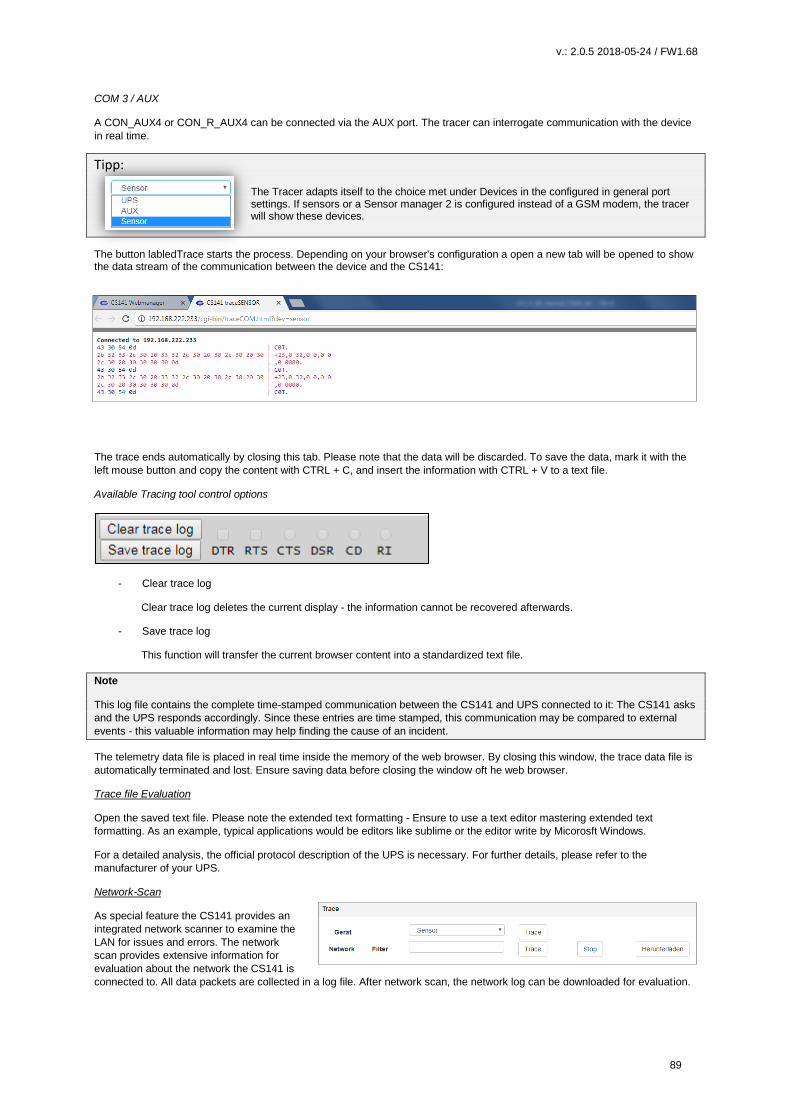
v.: 2.0.5 2018-05-24 / FW1.68
89
COM 3 / AUX
A CON_AUX4 or CON_R_AUX4 can be connected via the AUX port. The tracer can interrogate communication with the device
in real time.
Tipp: The Tracer adapts itself to the choice met under Devices in the configured in general port settings. If sensors or a Sensor manager 2 is configured instead of a GSM modem, the tracer will show these devices.
The button labledTrace starts the process. Depending on your browser's configuration a open a new tab will be opened to show the data stream of the communication between the device and the CS141:
The trace ends automatically by closing this tab. Please note that the data will be discarded. To save the data, mark it with the
left mouse button and copy the content with CTRL + C, and insert the information with CTRL + V to a text file.
Available Tracing tool control options
- Clear trace log
Clear trace log deletes the current display - the information cannot be recovered afterwards.
- Save trace log
This function will transfer the current browser content into a standardized text file.
Note
This log file contains the complete time-stamped communication between the CS141 and UPS connected to it: The CS141 asks
and the UPS responds accordingly. Since these entries are time stamped, this communication may be compared to external
events - this valuable information may help finding the cause of an incident.
The telemetry data file is placed in real time inside the memory of the web browser. By closing this window, the trace data file is
automatically terminated and lost. Ensure saving data before closing the window oft he web browser.
Trace file Evaluation
Open the saved text file. Please note the extended text formatting - Ensure to use a text editor mastering extended text
formatting. As an example, typical applications would be editors like sublime or the editor write by Micorosft Windows.
For a detailed analysis, the official protocol description of the UPS is necessary. For further details, please refer to the
manufacturer of your UPS.
Network-Scan
As special feature the CS141 provides an
integrated network scanner to examine the
LAN for issues and errors. The network
scan provides extensive information for
evaluation about the network the CS141 is
connected to. All data packets are collected in a log file. After network scan, the network log can be downloaded for evaluation.
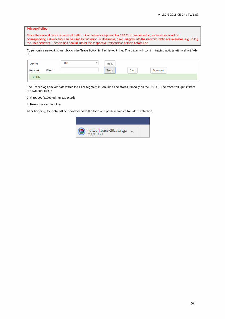
v.: 2.0.5 2018-05-24 / FW1.68
90
Privacy Policy:
Since the network scan records all traffic in this network segment the CS141 is connected to, an evaluation with a
corresponding network tool can be used to find error. Furthermore, deep insights into the network traffic are available, e.g. to log
the user behavior. Technicians should inform the respective responsible person before use.
To perform a network scan, click on the Trace button in the Network line. The tracer will confirm tracing activity with a short fade
in.
The Tracer logs packet data within the LAN segment in real-time and stores it locally on the CS141. The tracer will quit if there
are two conditions:
1. A reboot (expected / unexpected)
2. Press the stop function
After finishing, the data will be downloaded in the form of a packed archive for later evaluation.
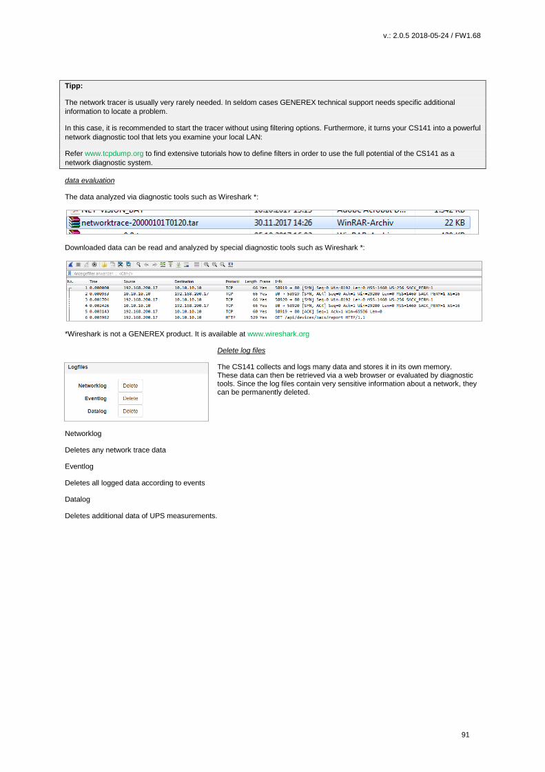
v.: 2.0.5 2018-05-24 / FW1.68
91
Tipp:
The network tracer is usually very rarely needed. In seldom cases GENEREX technical support needs specific additional
information to locate a problem.
In this case, it is recommended to start the tracer without using filtering options. Furthermore, it turns your CS141 into a powerful
network diagnostic tool that lets you examine your local LAN:
Refer www.tcpdump.org to find extensive tutorials how to define filters in order to use the full potential of the CS141 as a
network diagnostic system.
data evaluation
The data analyzed via diagnostic tools such as Wireshark *:
Downloaded data can be read and analyzed by special diagnostic tools such as Wireshark *:
*Wireshark is not a GENEREX product. It is available at www.wireshark.org
Delete log files
The CS141 collects and logs many data and stores it in its own memory. These data can then be retrieved via a web browser or evaluated by diagnostic tools. Since the log files contain very sensitive information about a network, they can be permanently deleted.
Networklog
Deletes any network trace data
Eventlog
Deletes all logged data according to events
Datalog
Deletes additional data of UPS measurements.

v.: 2.0.5 2018-05-24 / FW1.68
92
Changing logo
Some companies do not want foreign logos inside their IT Infrastructure. Therefore, it is possible to change the logo shown on
the upper left side.
How to change the logo
1. Open the graphic program of your choice
2. Create a new picture, maximum size is 200 X 54 PX
3. Edit the logo as your whish
4. When finished, save the logo with filename logo.gif – otherwise it will not work.
5. Open CS141 Toolbox:
Under Tools, you will find the configuration screen:
Use drag and drop to insert the new logo or click to select from a list.
6. Press Upload to insert the new logo.
Before…
… and after
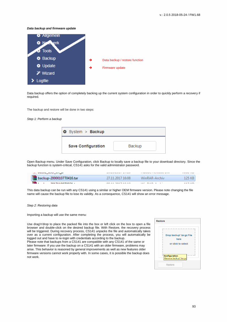
v.: 2.0.5 2018-05-24 / FW1.68
93
Data backup and firmware update Data backup / restore function
Firmware update
Data backup offers the option of completely backing up the current system configuration in order to quickly perform a recovery if required.
The backup and restore will be done in two steps:
Step 1: Perform a backup
Open Backup menu. Under Save Configuration, click Backup to locally save a backup file to your download directory. Since the backup function is system-critical, CS141 asks for the valid administrator password.
This data backup can be run with any CS141 using a similar or higher OEM firmware version. Please note changing the file
name will cause the backup file to lose its validity. As a consequence, CS141 will show an error message.
Step 2: Restoring data
Importing a backup will use the same menu:
Use drag'n'drop to place the packed file into the box or left click on the box to open a file browser and double-click on the desired backup file. With Restore, the recovery process will be triggered. During recovery process, CS141 unpacks the file and automatically takes over as a current configuration. After completing the process, you will automatically be logged out and have to re-login with credentials according to the backup. Please note that backups from a CS141 are compatible with any CS141 of the same or
later firmware: If you use the backup on a CS141 with an older firmware, problems may
arise. This behavior is reasoned by general improvements as well as new features older
firmware versions cannot work properly with. In some cases, it is possible the backup does
not work.
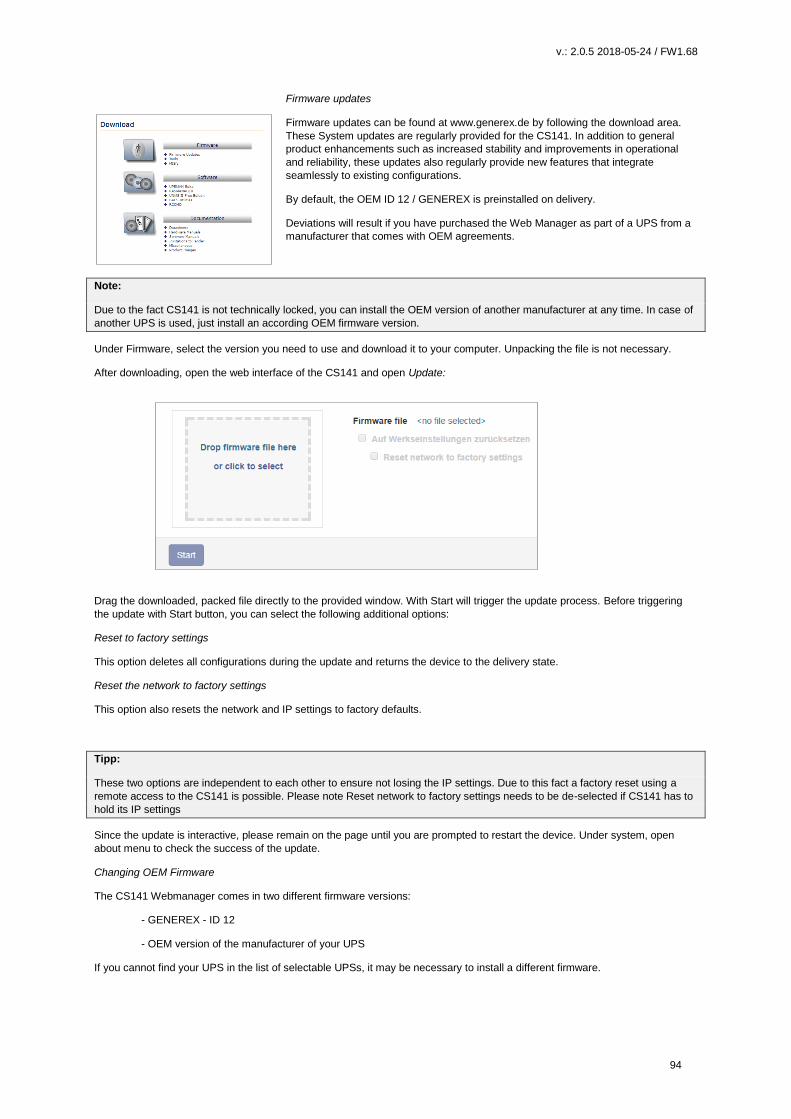
v.: 2.0.5 2018-05-24 / FW1.68
94
Firmware updates
Firmware updates can be found at www.generex.de by following the download area.
These System updates are regularly provided for the CS141. In addition to general
product enhancements such as increased stability and improvements in operational
and reliability, these updates also regularly provide new features that integrate
seamlessly to existing configurations.
By default, the OEM ID 12 / GENEREX is preinstalled on delivery.
Deviations will result if you have purchased the Web Manager as part of a UPS from a
manufacturer that comes with OEM agreements.
Note:
Due to the fact CS141 is not technically locked, you can install the OEM version of another manufacturer at any time. In case of
another UPS is used, just install an according OEM firmware version.
Under Firmware, select the version you need to use and download it to your computer. Unpacking the file is not necessary.
After downloading, open the web interface of the CS141 and open Update:
Drag the downloaded, packed file directly to the provided window. With Start will trigger the update process. Before triggering
the update with Start button, you can select the following additional options:
Reset to factory settings
This option deletes all configurations during the update and returns the device to the delivery state.
Reset the network to factory settings
This option also resets the network and IP settings to factory defaults.
Tipp:
These two options are independent to each other to ensure not losing the IP settings. Due to this fact a factory reset using a
remote access to the CS141 is possible. Please note Reset network to factory settings needs to be de-selected if CS141 has to
hold its IP settings
Since the update is interactive, please remain on the page until you are prompted to restart the device. Under system, open
about menu to check the success of the update.
Changing OEM Firmware
The CS141 Webmanager comes in two different firmware versions:
- GENEREX - ID 12
- OEM version of the manufacturer of your UPS
If you cannot find your UPS in the list of selectable UPSs, it may be necessary to install a different firmware.

v.: 2.0.5 2018-05-24 / FW1.68
95
For this, it is necessary to understand how you can detect the currently installed firmware and the required firmware:
The current firmware
You can see the current firmware by the logo in the top left corner:
Depending on the manufacturer, you will find the corresponding logo.
Checking firmware version
In the general system information, you will find this entry
The firmware version shows the OEM key: V1.64 the current firmware .12 the currently installed OEM version 171213 read the creation date backwards If you want to operate the CS141 in a UPS of another manufacturer, you will find the necessary firmware on www.generex.de in the download area
Use the Show Version Info to check if an updated firmware is available for download. Please note that unlike updating within the
same OEM firmware, changing the OEM firmware requires triggering a factory default setting since features and functions may
vary among UPS manufacturers.
v.: 2.0.5 2018-05-24 / FW1.68
96
Most commen problems while configuration and updating
This list contains typical errors that can occur when dealing with firmware updates: Dip-switches / slide switch in wrong position As a result, the CS141 uses either at the configuration mode IP address or an IP address assigned via DHCP. In this case you can no longer reach the CS141. Since the configuration mode on the hardware side has the 10.10.10.10 as a pre-set, it may also cause a network error, since this IP address will be used by any CS141 as a default. Forgot manual IP address assignment or IP address set to factory default The CS141 boots up and tries to get an IP address. If this is not possible, it starts with the default IP 10.10.10.10. Forgotten Reboot Since the CS141 offers the possibility to change the sliding switch on the fly and to carries out the function via software reboot, an update can evidently trigger the change of the IP address and the CS141 is no longer accessible. The reason for this is that the CS141 starts regularly with 10.10.10.10 and points the route to it on the local PC: if you boot the CS141 the first time, set the sliding switch to manual mode, enter IP address data and than perform an update, only the IP settings you entered will be used. As a consequence, it seems CS141 can not be accessed at the hardcoded IP address 10.10.10.10. Web Browser caching caused issues Modern web browsers use technologies designed to speed up content viewing and improving multimedia experiences: - Speech recognition - Auto-complete names and address data - Automatic login into websites - Personalized commercials - Pre-caching files from websites - Holding website files for faster revisit - and many more … These media files are loaded into a separate browser cache to ensure the fastest and most comfortable possible web experience. The CS141 uses build-in web-based technology. If you use more than one CS141, webbrowsers sometimes show pre-cashed data: Mixing identical content from different devices can cause strange or illogical error messages.
Note: This is caused by webbrowsers' behavior. In this case, the browser cache must be deleted.
Force https is active Depending on patchlevel and webbrowser used for displaying web-based content, some web browsers tend to detect this condition and automatically add the https. However, others ignore the wrong http query and return a device is not available message or react in a very strange way: https was sometimes automatically enabled, but the https-query will be redirected to another device. In this case, browser logged your surf behavior and assumed that you meant another device that is known to use https. As a result, you enter the IP address http://192.168.3.15 and https://192.168.3.56 will be shown. At https://192.168.3.15, however, it would have been the correct CS141 been displayed. Again, the behavior of the web browser is involved to cause some confusion. Deleting the browser cache will fix it.

v.: 2.0.5 2018-05-24 / FW1.68
97
If nothing works…
The CS141 comes with two possible options if a problem needs to reinitialize the firmware or resetting the device to factory defaults. If the CS141 does not allow a login or the interface shows a faulty display, but still can be reached regularly, administrators may try the following: http: // <IP address> / reboot This option allows you to force a restart of the CS141 directly. http: // <IP address> / update This option takes administrators directly to the update screen without the need for logging in
From now you can select the desired firmware package by drag & drop or by clicking the button. If necessary, you can use the Reset to factory defaults function to reset the CS141 to factory settings. All configurations are deleted and the device is set to startup configuration. Enter the password for the administrator account, if you are not in configuration mode. The process starts and after successful flashing the standard login screen will be shown.
Note: If you have lost the administrator password, move the DIP switch to center position. After cold boot, it is possible to flash the device directly. Enter the following line in your web browser: http://10.10.10.10/update As a consequence, the administrative password will be set to default setting.
Starting the rescue system If this feature is not available, the CS141 offers second option: During flashing, the CS141 saves a complete backup including the configuration of the “last known: good”. This version can be activated by setting the following jumper:

v.: 2.0.5 2018-05-24 / FW1.68
98
If the jumper is set and the adapter boots, CS141 will run this version as a rescue system based on the last firmware version: Inside the About menu, the firmware version will add the word RESCUE to show its current operational mode. Rescue mode on CS141 mini Due to its compact design, the CS141 Mini has no jumper that can be set. To activate the rescue mode, set both DIP switches to the ON position: Run a firmware update and reset the adapter to factory settings. Please note you are not flashing the operating system of the
rescue mode:
You will not see the result until you return to normal operating mode and restart the CS141.
v.: 2.0.5 2018-05-24 / FW1.68
99
Appendix
FAQ-Frequently asked questions
What does systemn error 500 / 503 mean?
This error occurs if the web server of the CS141 is not running correctly. If the problem persists after restarting the
adapter, the firmware must be updated / re-imported. This is recommended in conjunction with a reset to factory
settings
What does error 422 mean?
This error occurs when trying to adjust the configuration of certain values while using older firmware versions.
Updating to the current firmware version shall fix it.
Was bedeutet Fehler 400 / 420/ 522?
This issue can occur if the firmware has been updated but the browser uses data cached from previous versions.
Clearing browser cache should fix it. In rare cases the CS141 needs a cold reboot. Please note, a cold reboot of the
CS141 will not affect the UPS.
Der USV status shows „Paused“.
When CS141 accesses the Alert History of the UPS, the normal connection must be temporarily stopped. By
switching to another page inside CS141 menu and pressing F5 to restore the display status (if not done automatically)
this should be fixed.
What does issue -1 mean?
This error occurs if no connection to CS141 is currently possible (CS141 reboots, network lost, etc.), but the user tries
to acces configuration screen. In this case the browser uses cached data to show the screen without the possibility to
enter values. In case of a reboot just give the CS141 a little bit more time.
A little bit awkward, butI forgot my password…
This happens to everyone now and then. Take a look at the "Rescue system" chapter - this might help you. If not,
contact [email protected] and we want to find a way to help you.
Why am I logged out when I disable the http tooltips?
Because the tooltips are related to the http service. Changing some values need to l redirect the user after restarting
the build-in http service.
The CON_R_AUX does not establish a connection!
This device is not supported by the CS141. You need to use the CON_R_AUX4.
I have entries in the log file called "UPSMAN started"
This entry is generated whenever there was a change in the event configuration: Because the changes are applied
immediately, the "UPSMAN service" must be restarted - this will be protocolled.
When accessing the Alert History, I only get an error!
Maybe this function is not supported by the selected UPS. The fact the CS141 supports your UPS does not mean,
your UPS supports all function available at the CS141 for this UPS. This is a little bit complicated to explain:
sometimes the UPS should support a command, but ignores it consequently.
I get the error "Backend busy" when I try to log in!
Please wait a moment and try again with another browser. If the problem persists after 5 minutes, use the / reboot
function. Refer the chapter If nothing works ...
Does the CS141 supports SNMP v1 queries?
Maybe ... yes or no ...
The CS141 has never or will officially support SNMP queries v1.0. On the other hand it does not mean that it can not if
you wish to do that. The only issue that might prevent you using the CS141 the way you want: Due to the fact this is
officially not supported, there will be no official bug fix if you have problems. Inoffically maybe our developers can do
something if they know somethings not working as it should ...
I have questions that are not explained in the manual.
We always strive to improve our documentation. If you have something that is not or insufficiently explained, please
send us a short message to [email protected] - We are happy to help you as fast as possible.
v.: 2.0.5 2018-05-24 / FW1.68
100
Copyright and licenses
The copyright authorization from Generex and other relevant software suppliers must be respected.
Generex and their suppliers reserve the rights to the software components.
In particular the following are prohibited:
copying and distribution,
modifications and derivations,
decompilation, reverse engineering,
Components which fall under GNU General Public License and further Open Source licenses are
integrated into the software. An overview of the integrated Open Source components and a copy of the
current license can be obtained at www.generex.de/legal/sla.
Generex will provide the source code for all components of software licensed under the GNU General
Public License and comparable Open Source licenses.
For source code requests, please email [email protected].