upper saucon township lehigh county … · upper saucon township . lehigh county . pennsylvania ....
TRANSCRIPT

UPPER SAUCON TOWNSHIP LEHIGH COUNTY PENNSYLVANIA
STANDARD SEWER SPECIFICATIONS
REVISION DATE
February 6, 2017
As Prepared By
SCHREITER ENGINEERING ASSOCIATES, Inc. 7 RALEIGH DRIVE
DOWNINGTOWN, PA 19335

TABLE OF CONTENTS
UPPER SAUCON TOWNSHIP JUNE 1, 2014
TC/1
SPECIFICATIONS SECTION TITLE REVISION DATE 01010 INTRODUCTION February 6, 2017 01030 LOCATIONS OF EXISITING LINES June 1, 2014 01300 SUBMITTALS June 1, 2014 01301 FACILITY TESTING REQUIREMENTS June 1, 2014 01450 FACILITY START UP AND June 1, 2014
ACCEPTANCE REQUIREMENTS 01500 TEMPORARY FACILITIES AND June 1, 2014
CONTROLS 02110 CLEARING AND GRUBBING June 1, 2014 02220 EARTHWORK FOR UTILITIES June 1, 2014 02230 ROCK EXCAVATION June 1, 2014 02551 GRAVITY SANITARY SEWERS AND June 1, 2014 APPURTENANCES 02552 PRESSURE SANITARY SEWERS June 1, 2014 AND APPURTENANCES 02560 MANHOLES June 1, 2014 02569 GREASE INTERCEPTOR June 1, 2014 02605 ROADWAY PAVING June 1, 2014 02606 DRIVEWAY PAVING June 1, 2014 02810 RESTORATION OF DISTURBED June 1, 2014
AREAS 02980 STATE ROAD CROSSING June 1, 2014 03301 CAST IN PLACE CONCRETE June 1, 2014

TABLE OF CONTENTS
TC/2
DETAIL DRAWINGS
PLATE NO. ITEM REVISION DATE DD1 DROP MANHOLE - PVC PIPE June 1, 2014
INSTALLATION DD2 DROP MANHOLE - ALL PIPE June 1, 2014
EXCEPT PVC DD3 TYPICAL SHALLOW MANHOLE June 1, 2014 DD4 PRECAST MANHOLES WITH June 1, 2014
CONCRETE BASE DD5 POURED CONCRETE BASE June 1, 2014 DD6 PRECAST MANHOLE BASE June 1, 2014 DD7 PRECAST MANHOLE JOINT DETAILS June 1, 2014
AND TRANSITION DETAILS
DD8 JOINT DETAIL June 1, 2014 DD9 STANDARD MANHOLE GRADE RING June 1, 2014 DD10 30" CAST IRON MANHOLE FRAME June 1, 2014
AND COVER DD11 CAST IRON WATERTIGHT June 1, 2014
MANHOLE FRAME AND COVER DD12 DROP FRONT MANHOLE STEP June 1, 2014 DD13 ANCHOR BOLT DETAIL June 1, 2014 DD14 TYPICAL CONNECTION TO June 1, 2014 EXISTING MANHOLE DD15 DOGHOUSE TYPE MANHOLE June 1, 2014 DD16 LOW PRESSURE SEWER June 1, 2014
FLUSHING MANHOLE
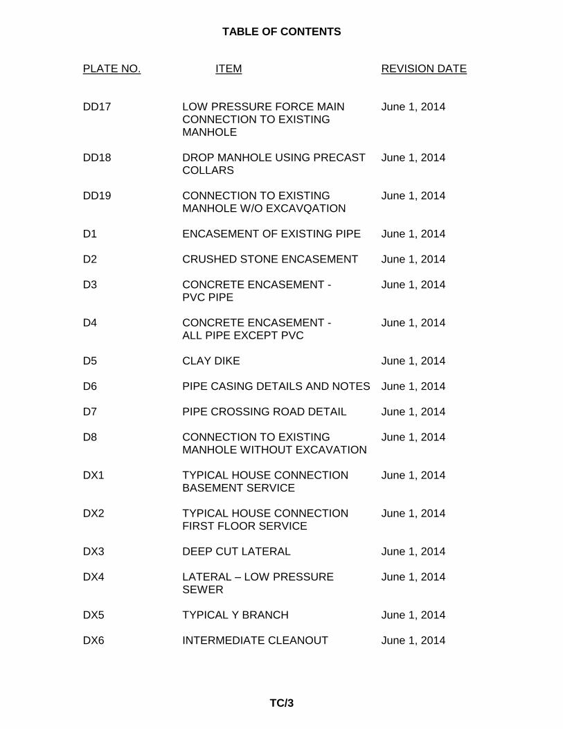
TABLE OF CONTENTS
TC/3
PLATE NO. ITEM REVISION DATE DD17 LOW PRESSURE FORCE MAIN June 1, 2014
CONNECTION TO EXISTING MANHOLE
DD18 DROP MANHOLE USING PRECAST June 1, 2014
COLLARS
DD19 CONNECTION TO EXISTING June 1, 2014 MANHOLE W/O EXCAVQATION
D1 ENCASEMENT OF EXISTING PIPE June 1, 2014 D2 CRUSHED STONE ENCASEMENT June 1, 2014 D3 CONCRETE ENCASEMENT - June 1, 2014
PVC PIPE D4 CONCRETE ENCASEMENT - June 1, 2014
ALL PIPE EXCEPT PVC D5 CLAY DIKE June 1, 2014 D6 PIPE CASING DETAILS AND NOTES June 1, 2014 D7 PIPE CROSSING ROAD DETAIL June 1, 2014 D8 CONNECTION TO EXISTING June 1, 2014 MANHOLE WITHOUT EXCAVATION DX1 TYPICAL HOUSE CONNECTION June 1, 2014
BASEMENT SERVICE DX2 TYPICAL HOUSE CONNECTION June 1, 2014
FIRST FLOOR SERVICE DX3 DEEP CUT LATERAL June 1, 2014 DX4 LATERAL – LOW PRESSURE June 1, 2014
SEWER DX5 TYPICAL Y BRANCH June 1, 2014 DX6 INTERMEDIATE CLEANOUT June 1, 2014

TABLE OF CONTENTS
TC/4
PLATE NO. ITEM REVISION DATE DX7 TYPICAL THRUST BLOCKS June 1, 2014 DX8 STANDARD GRINDER PUMP June 1, 2014
INSTALLATION DX9 SADDLE CONNECTION FOR June 1, 2014 EXISTING SEWER DX10 TOWNSHIP ROADWAY FLEXIBLE June 1, 2014 PAVEMENT RESTORATION DX11 DRIVEWAY FLEXIBLE PAVEMENT June 1, 2014 RESTORATION DX12 DEEP SEWER LATERAL June 1, 2014
CONNECTION AT MANHOLE
DX13 DEEP SEWER LATERAL June 1, 2014 CONNECTION AT EXISTING SEWER
DX14 LOW PRESSURE SEWER June 1, 2014 CONNECTION AT EXISITNG GRAVITY SEWER MAIN
DX15 DEEP SEWER LATERAL June 1, 2014
DX16 CLEANOUT BOX June 1, 2014 DX-17 CAPPING OF EXISTING SEWER December 1, 2015
LATERAL PIPE (TC PIPE) DX-18 CAPPING OF EXISTING SEWER December 1, 2015
LATERAL PIPE (PVC PIPE) DX-19 LATERAL LOCATEDADJACENT TO February 6, 2017 STORM WATER DISPERSAL BED

Section 01010 INTRODUCTION
UPPER SAUCON TOWNSHIP February 6, 2017
01010/1
1.1 SCOPE
A. These specifications have been adopted by Upper Saucon Township to specify the manner in which sanitary sewers, manholes, and all related appurtenances shall be constructed and installed.
B. The Developer/Builder shall, prior to and at all times during construction
comply with all rules, regulations, and requirements of Upper Saucon Township, the jurisdiction within which the Work is being (or is to be) performed, the Pennsylvania Department of Environmental Protection and, where applicable, all Federal Regulatory Agencies.
C. Before the Work is started at the construction site, the Developer/Builder
shall notify, in writing, the following: the Township building or zoning inspector, the Police Department, the Fire Department, the Southern Lehigh School District transportation coordinator, and all utility companies serving the area of the Work, and the Pennsylvania One Call System (see Article 2.7A, 1.a of this Section).
D. The Township, at its sole discretion, shall at all times have and hereby
reserves the right to visit the construction site from time to time and at all times and inspect the installation of the Work.
E. The Township may require corrective actions to assure compliance with
these specifications in which case the Developer/Builder shall comply with all instructions of the Township at his(its) sole cost and expense.
F. If the Developer/ Builder or landowner is required by the Board of
Supervisors of Upper Saucon Township to enter into a Subdivision and Land Development Agreement, the terms and condtions of said agreement shall take precedence over all matters in this ordinance where conflict may occur.
1.2 DEFINITIONS
A. Wherever the word "Township" is used herein, it shall mean "Upper Saucon Township”.
B. Wherever the word "Authority" is used herein, it shall mean "Upper
Saucon Township Municipal Authority”.
C. Wherever the word "Developer/Builder" is used herein, it shall mean the "developer" or "builder" doing the Work.

Section 01010 INTRODUCTION
01010/2
D. Wherever the words "Approved Plans" are used herein they shall mean the Developer/Builder's Construction Plans, approved by the Township and Authority.
E. Wherever the word "Owner" is used herein it shall mean "Upper Saucon
Township Municipal Authority". F. Wherever the word "Work" or "Improvements" is used it shall mean the
project proposed to be or which is or has been constructed by Developer/Builder in accordance with the intent of the Approved Plans.
G. Whereever the word “Superintendent” is used, it shall mean the “Director
of Water/Sewer Resources”. PART 2 - REQUIREMENTS 2.1 PLAN REVIEW
A. All plans must be submitted to the Township following the Township;’s current requirements for submission of Land Development projects.
B. The Authority's Engineer review of the Developer/Builder's construction
plans shall be for general conformance with these Standard Specifications. Also, the review shall be for sound construction technique and procedures, current Pennsylvania Department of Environmental Protection requirements, and the general requirements of the Township and Authority.
C. Developer/Builder shall be and remain responsible for implementation of
the Authority Specifications, requirements and Township Ordinances and shall obtain and become familiar with all such Township Ordinances prior to the commencement of construction of the Work.
D. Developer/Builder shall be and remain responsible for: (1) the accuracy of
the Approved Plans ; (2) the completion of the Work as shown and specified on the Approved Plans; and (3) the performance and function(s) of the facility as designed and intended as shown on the Approved Plans.
E. Developer/Builder shall be and remain responsible for locating and
determining the size, and type of all existing utilities all of which shall be shown on the plans proposed to become Approved Plans.

Section 01010 INTRODUCTION
01010/3
2.2 SUBMITTALS
A. Pre-Construction Meeting
1. One (1) week prior to initiation of any phase of construction, the Developer/Builder shall schedule a pre-construction meeting to be held at the Township Building or any other location that has been previously approved by the Township Manager. The meeting shall be conducted by the Township or its designated representative. Attendance at the meeting of the Developer/Builder and his (its) contractor(s) is mandatory. It is also the Developer/Builder's sole responsibility to issue written notice of the upcoming pre-construction meeting to those entities listed in Article 1.1 C of this Section as well as the contractor(s) he will employ to construct those facilities shown on the Approved Plans. The Pre-construction meeting is mandatory and no construction can commence before such a meeting is held. Notes of the meeting will be prepared by the Township and distributed to all attendees.
B. The Developer/Builder shall submit to the Township copies of all required
permits, approved plans, and other various requirements as itemized herein.
C. All submittals shall be made in accordance with Section 01300-
SUBMITTALS of these Standard Specifications. D. The Developer/Builder shall, in accordance with the following schedule,
transmit to the Township three (3) sets of the following data, unless advised in writing that such submittal is not required or the context of the Work clearly indicates that any required submittal is not relevant to the Work.
1. Two (2) weeks prior to initiation of any phase of construction but
prior to the Pre-construction Meeting noted above..
a. Approved Plans b. Copies of Pennsylvania Department of Environmental
Protection Modules with approvals attached. c. Pennsylvania State Highway Occupancy Permit d. Local Highway Occupancy Permit e. Railroad Permit

Section 01010 INTRODUCTION
01010/4
f. Erosion and Sediment Control Plan Approval Letter g. Shop Drawings of the following: (See, Section 01300,
SUBMITTALS for the type and number of copies required).
(1) Pipe and appurtenances (2) Manholes (precast M.H. only) with pipe adapter
(3) Manhole frames and covers (4) Fittings (wyes, elbows, etc.) (5) Stake out cut sheets (6) All other appurtenant data
h. A Blasting Plan which shall outline all proposed blasting
within the Work and shall indicate the procedures and safeguards which shall be implemented to carry out the proposed blasting activities.
i. Insurance Certificates j. Progress of work schedule (See Section 01300, Part 2)
2. During construction but prior to completion of construction:
a. Letters of Certification as to compliance with these
specifications for:
(1) Backfill material
(2) Pipe bedding material
(3) Concrete
b. Soil test reports

Section 01010 INTRODUCTION
01010/5
3. After construction but prior to start of the Maintenance Bond
a. Blasting records which shall include a report including the following concerning each and every use of explosive material:
i. Shall state the date and time of each such use, the location of each such use,
ii. The persons present during each such use, any observations of damage or harm or adverse effect on surrounding property or persons, and
iii. Shall state the safeguards used during each event and such other matters as may be required by these specifications or as directed by the Township.
b. Paving core tests(s) where required c. Record Drawings d. Copies of all test reports
e. Maintenance Bond or other security satisfactory to the
solicitor to the Township f. Letter that all punch list items were completed
2.3 INSURANCE
A. The Developer shall demonstrate its ability to protect the Township and/ or other entities and/or persons as required in the Subdivision and Land Development Agreement, and in order to protect and insure the Township and/ or other entities and/ or persons against liability with respect to the Developer's construction and/ or installation of the Improvements covered by these specifications.
B. Before any building permit is issued to the Developer and before the Developer or any of the Developer's agents, employees, contractors, or subcontractors enter upon the Premises or conduct any earth moving activities, construction activities, or perform any other site improvement activites, the Developer shall:
1. Secure and maintain in force until all of the Improvements have
been constructed/ installed, inspected, and approved by the Township (or Authority as appropriate):

Section 01010 INTRODUCTION
01010/6
a. Comprehensive Commerical General Liability Insurance including "premises operations" and "products and completed operations" coverages with not less than a $1,000,000.00 combined single limit naming as additional insureds "Upper Saucon Township and its Boards, Commissions and Authorities (including the individual members thereof)” and their elected and appointed officers, officals, employees, professional consultants and agents.
b. Commerical Motor Vehicle Insurance coverage.
c. Workman's Compensation coverage, if required and as
required by state law.
2. Cause each said insurance policies to include an endorsement which specifically provides that the policy(ies) shall not be cancellable or subject to admendment or modifications (affecting or reducing) coverage (except for additions to or increases in the coverages) without ten (10) days advance written notice to the Township, 5500 Camp Meeting Road, Center Valley, PA 18034.
3. Furnish the Township with a certificate of insurance reflecting that
the required insurance coverage and endorsements are in effect along with proof of prepayment of the annual premium therefor, and thereafter, at least annually, furnish the Township with a Certificate of Insurance evidencing continuing compliance with this requirement until the project is completed and all Improvements have been installed/ constructed/ erected and approved by the Township Engineer.
4. Require of all contractors and subcontractors which will be
preforming any work on the Premises on the construction/ installation of the Improvements that each such contractor and subcontractor before entering upon the Premises to perform any work provide the Developer and the Township a Certificate of Insurance evidencing that said subcontractor has in force at least the insurance coverages identifed in sections 2.3.A.1.a, 2.3.A.1.b., and 2.3.A.1.c. above (including the additional insured endorsement set forth in section 2.3.A.1.a) and with the endorcement identified in section 2.3.A.2 above.

Section 01010 INTRODUCTION
01010/7
2.4 ROCK EXCAVATION
A. All Blasting shall be planned and performed by an experienced licensed plaster. All blasting shall be performed under the supervision of a experienced licensed Professional Engineer or Professional Geologist who is licensed to practice in the State of Pennsylvania, as described in Section 02230, ROCK EXCAVATION, and in accordance with sound and safe construction practices.
2.5 TESTING
A. All testing as described in Section 02220, EARTHWORK FOR UTILITIES of these Specifications shall be performed by a reputable Soils Engineering and Testing Laboratory when required by the Township or Authority.
2.6 BUILDING SEWERS
A. Building sewers (laterals) are to be installed from the sewer to the street right of way line or easement boundary in accordance with these Specifications. Laterals installed from the street right-of-way line or easement boundary to the building shall be installed in accordance with with these Specifications.
B. All laterals will be constructed following requirements for sanitary sewer
piping as shown in Section 02551(GRAVITY SANITARY SEWERS AND APPURTENANCES) and Section 02552 (PRESSURE SANITARY SEWERS AND APPURTENANCES).
B. Laterals will contain no bends greater than 45 degree bend. All laterals
will include cleanouts at each change of lateral direction or every one hundred (100) feet of lateral length.
C. A trap, vent and cleanout shall be installed immediately outside the
building exterior wall. At the curb/street line a cleanout shall be installed. D. All gravity laterals servicing single residential units will be constructed
using either 4 or 6 inch diameter pipe. All gravity laterals servicing buildings with multiple residential units or industial/ commerical units will be constructed using 6 inch diameter pipe unless authorized by the Authority Engineer in writing. Laterals shall have the following minimum and maximum slopes:

Section 01010 INTRODUCTION
01010/8
Pipe Size
Minimum Slope
Maximum Slope
4
2.00%
15.00%
6
1.00%
9.00%
E. If directed by the Authority Engineer, the developer may be required to install manholes in laterals that extend over 100 ft. These manholes would be installed at each change of diection to provide access for future maintenance.
F. Intermediate cleanouts shall be required every 100 feet or change of
direction greater than 22.5o. Cleanout locations may be modified if approved in advance by the Authority Engineer.
G. For new construction all laterals shall be made through the use of “wye
branches”. The minimum diameter of the laterals shall be six (6) inches. The 6” lateral shall run to the curb or street right-of-way line. It shall be securely capped and a 2” x 6” board placed behind the cap extended vertically to minimum of 12” above finished grade. The lateral shall include a cleanout located on the curbside of the street outside of the street cart path.
HH.. For laterals tying into an existing sewer main, the contractor shall
excavate from the main to the building. The Township will install the sewer saddle on the main. The contractor shall then install the lateral from the sewer saddle to the building. The contractor/plumber shall be responsible for roadway restoration to conform to Township specifications. The lateral shall include a cleanout located on the curb side of the street outside of the street cart path.
I. All pressure sewer laterals used in conjuction with grinder pump units
shall be a minimum of 1½ inch diameter pressure sewer pipe. A transition connection as shown on the Standand Drawings shall be installed at the point where the lateral changes from pressure to gravity type lateral. The Developer shall be responsible for installation of all necessary pressure and/or vacumm relief valves.
J. Laterals will be used to provide sewage service to no more than one
building or structure. All sewage piping providing service to more than one building or structure will be classified as private sanitary sewer extension.
K. It shall be the property owners responsibility to maintain and repair their
own sewer lateral from the structure to the sewer main.

Section 01010 INTRODUCTION
01010/9
2.7 SPECIAL PRECAUTIONS
A. Description of Work
1. The Developer/Builder affected by utilities shall make appropriate arrangements with the utility companies to provide for services necessary to complete the work. The Developer/Builder shall comply with all protection requirements for the existing utilities.
a. Prior to construction, the Developer/Builder shall determine
in the field the exact location and depth of all affected existing utility lines in accordance with Pennsylvania Act 38 of 1991 (Pennsylvania One Call System - 800 242-1776), which replaces Act 172 of 1986.
2. Contact the utility company to provide exact location of utility before
excavation or demolition work is started.
3. Attention is directed to the fact that there may be other lines in certain locations in addition to the recorded locations.
B. Relation of New Sewers to existing or Proposed Water Mains.
1. Horizontal and Vertical Separation: Sewers shall be laid following
minimum requirements outlined in “Domestic Wastewater Facilities Manual”, (PADEP, August, 1991) or subsequent revisions.
C. Wells
1. Prior to construction of sewers the Developer/Builder shall locate all
domestic wells within the construction area. If a well falls within fifty (50) foot radius of the new sewer, the sewer shall be encased in concrete within the fifty (50) foot radius.
2. The Developer/Builder shall report to the Township any possibility
of damage to existing underground water supply or wells, that may be caused by blasting. In the event that the Developer/Builder's activities adversely affect the wells or the groundwater supply to wells, the Developer/Builder shall at his (its) sole cost and expense: (1) repair such damage within ten(10) days thereof, and (2) provide temporary water service until the original well flow rate(s) have been reestablished.

Section 01010 INTRODUCTION
01010/10
D. Septic Systems
1. Any septic systems which are adversely affected by the Developer/Builder during construction shall be repaired and returned to operational status as quickly as possible, at no cost to the Owner and in no event later than five (5) days after the damage has been discovered. The Developer/Builder shall, in addition, provide temporary sewage collection and treatment service to the property whose septic system has been damaged until the original system has been restored to the condition that existed prior to the damage.
E. Safety and Protection
1. The Developer/Builder shall initiate, formulate, supervise, review,
and oversee any and all safety precautions, practices, procedures, and programs which are or should be provided in connection with the Work. Developer/Builder will take all necessary or proper precautions for the safety of and will provide the necessary protection to prevent damage, injury or loss to:
a. All employees on the Work and any other person who may
be affected thereby whether or not such person is involved with the Work.
b. All the Work and all materials or equipment to be
incorporated therein whether in storage, on the site, or off the site.
c. Other property at the site or adjacent thereto, including
trees, shrubs, lawns, walks, pavements, roadways, structures and utilities not designated for removal, relocation or replacement in the course of construction.
d. The Work itself
F. Installation of Clay Dikes
1. Clay or bentonite dikes will be installed every twenty feet along all
sewer pipes and/ or laterals located in an carbonate geologic areas as required by the Township.

Section 01010 INTRODUCTION
01010/11
G. Sedimentation and Erosion Control
1. It shall be the Developer/Builder’s responsibility to implement all requirements of the Lehigh County Conservation District (LCCD) and the Township regarding sedimentation and erosion control.
H. Minimum/ Maximum Sewer Pipe Slopes
1. All sanitary sewers constructed in the Township will have a
minimum slope of 0.01 ft/ft. Where this slope requirement cannot be constructed, the Developer must provide written documentation detailing conditions present that limit pipe slope. The Develop must then receive the written approval of the Authority Engineer for use of any slopes less than 0.01 ft/ft.
2. All sanitary sewers constructed in the Township shall have a
maximum sewage velocity of 10 feet per second. All building sewers shall have a maximum slope as required in Paragraph 2.6.D of this section.
I. Minimum Sewer Depth
1. All gravity sewers shall be installed with a minimum cover of 4 feet. All sanitary force mains will require a minimum of 4 feet of cover.
2.8 ACCESS TO WORK
A. Representatives of the Township and Authority shall have safe access to the Work at all times. The Developer/Builder shall provide proper and safe facilities for such access and observation of the Work and also for any inspection or testing thereof by others.
2.9 TOWNSHIP MAY STOP THE WORK
A. If any aspect of workmanship or materials are defective or not in compliance with these Specifications or the Approved Plans, or is or are not otherwise in accordance with proper and safe construction practices and procedures the Township may: (1) order the Developer/Builder to stop the Work, or an portion thereof, until the cause for such order has been eliminated, (2) order Developer/Builder to promptly, and at no cost of expense to the Township or Authority, to correct such condition(s).

Section 01010 INTRODUCTION
01010/12
2.10 WARRANTY AND GUARANTEE
A. The Developer/Builder warrants and guarantees to the Township and Authority that all Work will be of good quality and free from faults or defects.
B. All unsatisfactory Work, all faulty or defective Work, and all Work not
conforming to the Approved Plans and these Specifications shall be considered defective.
C. The Township and Authority will give timely notice of all defects to
Developer/Builder which notice may be oral or written. D. At the option of the Township, all defective Work, whether or not in place,
may be rejected, or accepted, with or without requiring corrective action(s) from or of Developer/Builder.
2.11 TESTS AND INSPECTIONS
A. Where so indicated in these Specifications, or if the laws, ordinances, rules, regulations or orders of any public authority having jurisdiction require any Work to specifically be inspected, tested, or approved by some public body, the Developer/Builder shall assume full responsibility therefore, pay all costs in connection there with in and furnish the Township the required certificates of inspection, testing or approval.
B. The Developer/Builder shall give the Township a minimum of forty eight
(48) hours notice of readiness of the Work for all inspections or approvals. C. All gravity sanitary sewers and sewer laterals will be inspected by the
Township using television inspection equipment. The Developer/ Builder is responsible to reimburse the Township for all costs associated with this inspection work. The Developer/Builder is responsible to coordinate this inspection with the Superintendent of the wastewater treatment plant.
D. No Work shall be covered or otherwise obscured, in whole or in part, until
the Township has inspected and approved same in writing. Failure to comply with this provision shall result in a rejection of the work covered or obscured and shall result in a "dig up" of all such Work at Developer/Builder's expense.

Section 01010 INTRODUCTION
01010/13
2.12 FINAL INSPECTION
A. Upon written notice from the Developer/Builder that the project is complete, the Township will make a final inspection of the Work with or without Developer/Builder.
B. The Township will notify the Developer/Builder in writing of all particulars
in which this inspection reveals that the Work is incomplete or defective. C. The Developer/Builder shall immediately take such measures as are
necessary to remedy such deficiencies. 2.13 FINAL APPLICATION FOR ACCEPTANCE
A. After the Developer/Builder has completed the Work and any corrections thereto to the satisfaction of the Township, the Township shall issue a letter of final acceptance conditioned upon the Township's receipt of the following:
1. Requisite Maintenance Bond or provisions of a similar nature satisfactory to the Solicitor of the Township,
2. All schedules, guarantees, other bonds, certificates of inspection and other documents required by these specifications or otherwise lawfully required by the Township.
2.14 OFF ROAD EASEMENTS
A. The Developer/Builder shall provide a minimum 20 ft wide easement for all sanitary sewwers located outside of a road right of way that are to be dedicated to the USTMA.
B. The Developer/Builder shall provide a means for the access to all sanitary sewers located outside of a road right of way.
C. Where curbs are located adjacent to the off road easement, the
Developer must provide driveway cuts with a minimum width of 12 feet to provide access to the off road easement.
D. All off road easements shall provide access for Township equipment and
staff to perform television inspection and sewer cleaning activites using exisitng Township equipment.

Section 01010 INTRODUCTION
01010/14
E. The Developer/Builder shall be responsible to maintain all off road sanitary sewer easements until such sewers are formally dedicated to the USTMA by way of a bill of sale. This maintenance shall include all access roads or other means for the Township to perform television inspection and sewer cleaning activites.
F. The Developer/Builder shall be responsible to notify all property owners by
certified letter of the location of off road sanitary sewer easements. This notification shall include all restrictions as outlined in any Easement Agreement with the USTMA. Both the Township and Authority must be provided the written documentation that such notification was provided.
2.15 EIGHTEEN MONTH MAINTENANCE PERIOD
A. The Developer/Builder shall provide a Maintenance Bond or other security satisfactory to the Solicitor of the Township in an amount required under current Township requirements for Land Development.
B. If after final inspection and prior to the expiration of the eighteen (18)
month Maintenance Bond or such longer period of time as may be prescribed by law or by the terms of any applicable special guarantee lawfully required by the Township, any Work installed by the Developer/Builder is found to be defective, Developer/Builder shall promptly, in accordance with Township's written instructions, either correct such defective Work, or, if it has been rejected by Township, remove it from the site and replace it with non-defective Work.
C. If Developer/Builder does not promptly comply with the terms of such instructions, Township may have the defective Work corrected or the rejected Work removed and replaced, and all direct and indirect costs of such removal and replacement, including compensation for additional professional services including, but not limited to, legal and engineering and expert witness fees, costs and expenses, shall be paid by the Developer/Builder.

Section 01010 INTRODUCTION
01010/15
2.16 RECORD PLAN DRAWINGS
A. At completion of Work but prior to the start of the Maintenace Bond, the Developer/Builder shall provide the Township with two (2) sets of reproducibles of the original drawings (wash off Mylars), in a neat and clean condition, marked "Record Drawings." These "Record Drawings" shall, by dimensions and/or stationing, show the actual location and elevations of all pipe, manholes, laterals, wye fittings, and other structures installed during construction. Each sheet of these "Record Drawings" shall be signed by an official of the Developer/Builder's Company, certifying that each sheet reflects the as-constructed conditions. All Record Drawings shall be sealed by either a Professional Engineer or a Professional Surveyor licensed to practice in the Commonwealth of Pennsylvania.
B. The Developer/ Builder shall also provide the Township with two (2)
electronic copy of the record plans. The drawings shall be in an pdf format.
D. The Record Drawings required pursuant to these Specifications shall
include a certification which shall be signed by both of the following persons to show Record Plan conditions as follows: 1. Landowner on whose land the sewer facilities have been
constructed and
2. The licensed Professional Engineer or Professional Surveyor who was responsible for modifying or otherwise changing the originally Approved Plans:

Section 01010 INTRODUCTION
01010/16
WARRANTY The Owner of the land on which the improvements described and set forth on the within plan are situate, and his (or, if appropriate, its or their) licensed Professional Engineer or licensed Professional Surveyor, do hereby, jointly and severally, by their signatures affixed hereto, warrant and represent, intending to be legally bound hereby under and pursuant to the law of the Commonwealth of Pennsylvania, to Upper Saucon Township, its successors and assigns, which Township is hereby authorized and intends to relay upon, as follows: 1. The within plan was drawn by the undersigned engineer or surveyor who is a Registered Professional Engineer or a Registered Profissional Surveyor licensed to practice within the Commonwealth of Pennsylvania. Engineer or Surveyor, Name Written Engineer or Surveyor, Name Typed Engineer or Surveyor, Registration No. 2. If the plan to which this "Warranty" is affixed is or is intended to be a Record Plan, the following shall apply:
(a) that the improvements shown and described on the within plan exist in the form(s) and at the location(s) described herein, and
(b) that all of the materials shown on the within plan were actually used and do exist as depicted herein, and
(c) that all improvements described herein were built and constructed in a good, proper, and workmanlike manner, and
(d) that all improvements described herein were built and constructed strictly in accordance with the Ordinances of Upper Saucon Township.
Landowners Full Name, Written Landowner Full Name, Typed

Section 01010 INTRODUCTION
01010/17
C. Failure to timely provide the Record Plan(s) together with the required executed Warranty as set forth herein shall, at Township's option: (1) result in a rejection of the Work notwithstanding the fact that a letter of Final Acceptance may have already been issued and/or (2) result in the completion of the "Record Plans" plans by the Township at the cost and expense of the Developer/Builder for which purpose the Maintenance Bond and/or other security of Developer/Builder may be used in whole or in part by the Township.
END OF SECTION

Section 01030 LOCATIONS OF EXISTING LINES
UPPER SAUCON TOWNSHIP June 1, 2014
01030/1
PART 1 GENERAL 1.1 SCOPE
A. Description of Work
1. The Developer/Builder affected by utilities shall make appropriate arrangements with the utility companies to provide for services necessary to complete the work. The Developer/Builder shall comply with all protection requirements for the existing utilities.
a. Prior to construction, the Developer/Builder shall determine
in the field the exact location and depth of all affected existing utility lines in accordance with Pennsylvania Act 38 of 1991 (Pennsylvania One Call System - 800 242-1776), which replaces Act 172 of 1986.
2. Contact the User to provide exact location of Utility before
excavation or demolition work is started.
3. Attention is directed to the fact that there may be other lines in certain locations in addition to the recorded locations.
B. Related Work Specified Elsewhere
1. Act No. 1991-38
2. Excavation, Section 02220, EARTHWORK FOR UTILITIES.
3. Rock excavation, Section 02230, ROCK EXCAVATION.
1.2 SUBMITTALS
A. The Builder/Developer shall furnish Upper Saucon Township a certification listing the names of the users whom he has contacted both prior to as well as during course of construction.

Section 01030 LOCATIONS OF EXISTING LINES
01030/2
1.3 DEFINITIONS
A. The "Definitions" defined below are the definitions used in Act No. 1991-38, Commonwealth of Pennsylvania.
1. "Communications expenses" means the direct telecommunications
costs incurred by a one-call system in notifying a user of a potential excavation, including any costs billed directly to a user by a telecommunications company other than a one-call system.
2. "Contractor" means any person who or which performs excavation
or demolition work for himself or for another person.
3. "Demolition work" means the use of powered equipment or explosives to destroy or raze any structure.
4. "Designer" means any architect, engineer or other person who or
which prepares a drawing for a construction or other project which requires excavation or demolition work as herein defined.
5. "Emergency" means any condition constituting a clear and present
danger to life or property by reason of escaping gas, exposed wires, or other breaks or defects in a user's lines.
6. "Excavation work" means the use of powered equipment or
explosives in the movement of earth, rock or other material, and includes but is not limited to anchoring, augering, backfilling, blasting, digging, ditching, driving-in, grading, plowing-in, pulling-in, ripping, scraping, trenching and tunneling; but shall not include such use in agricultural operations nor operations necessary or incidental to the purposes of finding or extracting natural resources including all well site operations and shall not include work within a State highway right-of-way, performed by employees of the Commonwealth acting within the scope of their employment, which does not extend more than twenty-four inches beneath the existing surface or political subdivisions performing minor routine maintenance within the right-of-way of roads within their jurisdiction.
7. "Line" means an underground conductor or underground facility
used in carrying or providing electric or communication service, or an underground pipe used in carrying or providing gas, oil or oil product delivery, sewage, water or other service to one or more consumers or customers of such service and the appurtenances thereto. The term does not include storm drainage faciliites which are located within a public highway right-of-way. The term shall not

Section 01030 LOCATIONS OF EXISTING LINES
01030/3
include oil and gas production and gathering pipeline systems designed principally to collect oil or gas production from wells located in this Commonwealth provided such systems are marked or staked where they cross a public highway right-of-way.
8. "Minor routine maintenance" means shaping of or adding dust
palliative to unpaved roads, patching of the surface or base of flexible base, rigid base or rigid surface roads by either manual or mechanized method to the extent of the existing exposed base material, crack and joint sealing, adding dust palliative to road shoulders, patching of shoulders and shoulder bases by either manual or mechanized methods to the extent of the existing exposed base, and cleaning of inlets and drainage pipes and ditches.
9. "One-call system" means a communication system established
within this Commonwealth to provide a single telephone number for contractors or designers or any other person covered by this act to call to notify users of underground lines and pipe of the caller's intent to use powered equipment for excavating, tunneling, demolition or similar work. A one-call system shall be incorporated and operated as a nonprofit corporation pursuant to 15 Pa C.S. Part III (relating to corporations not- for-profit).
10. "Operator" means any individual in physical control of powered
equipment or explosives when being used to perform excavation or demolition work.
11. "Owner" means any person who or which engages a contractor for
a construction or other project which requires excavation or demolition work as herein defined.
12. "Person" means an individual, partnership, corporation, political
subdivision, a municipality, the Commonwealth and its agencies and instrumentalities, or any other entity.
13. "Powered equipment" means any equipment energized by an
engine or motor and used in excavation or demolition work.
14. "Site" means the specific place or places where excavation or demolition work is being or is to be performed.
15. "User" means the public utility, political subdivision, municipality,
authority, rural electric cooperative or its named representative trade association, or other person or entity who or which owns or

Section 01030 LOCATIONS OF EXISTING LINES
01030/4
operates a line. The term does not include the Commonwealth or its agencies.
16. "Working day" means any day except a Saturday, Sunday or legal
holiday prescribed by act of the General Assembly. PART 2 PRODUCTS 2.1 NONE PART 3 EXECUTION 3.1 GENERAL
A. It shall be the duty of each Developer/Builder as well as Developer/Builders' contractor who intends to perform excavation or demolition work within the Commonwealth to ascertain the exact location and type of users' lines which are located within the limits of work .
3.2 OBTAINING LOCATION OF EXISTING USERS' LINES
A. The Developer/Builder shall obtain the list of users from the Lehigh County Recorder of Deeds office.
C. Not less than three nor more than ten working days prior to the day of
beginning such work, the Developer /Builder shall notify each user of his intent to perform such work at its site or sites, and to request the information prescribed herein, from each such user's office. The Developer/Builder shall be deemed to have given the notice described in this clause if he calls a one-call system serving the location where the excavation is to be performed.
D. The Developer/Builder shall familiarize himself thoroughly with all
provisions and requirements of Upper Saucon Township and comply with same.

Section 01030 LOCATIONS OF EXISTING LINES
01030/5
E. The Developer/Builder , its design engineer, Contractor and Agents are cautioned that it is their responsibility alone to carefully locate, inspect, measure or otherwise field-check all locations, sizes, materials of construction, elevations, dimensions etc. of any Upper Saucon Township facility with which developer's facilities will connect or otherwise interact. In these instances, neither developer's engineer nor developer's contractor should in any way depend upon the accuracy of the Upper Saucon Township record plan information when designing any sewer, lateral, force main, etc. that connects into the Upper Saucon Township facilities. Upper Saucon Township nor Schreiter Engineering Associates, Inc. assumes any responsibility for the absolute accuracy of any Upper Saucon Township record plan information and it is incumbent upon developer, or developer's agents, to ascertain the exact characteristics of all Upper Saucon Township facilities prior to the initiation of construction.
END OF SECTION

Section 01300 SUBMITTALS
UPPER SAUCON TOWNSHIP June 1, 2014
01300/1
PART 1 GENERAL 1.1 SCHEDULES
A. The Developer/Builder shall be responsible for preparing a Progress or Work Schedule for the entire project prior to beginning work at the site.
1.2 SHOP DRAWINGS, SAMPLES AND MANUALS
A. The Developer/Builder shall process the Shop Drawings required by his Work to the Township and he shall be responsible for their timely submission in accordance with the Shop Drawing schedule which is included in the overall progress or work schedule as described in Part 2 of this Section.
B. Any proposed deviations/substitutions from that specified shall be clearly
noted on the cover letter transmitting the shop drawing. Failure to so note will be cause for rejection of equipment, materials, etc. after installation.
C. All submissions shall be marked with the Specification Section Number
containing the item submitted for review, or Drawing number for items specified on Drawings only.
D. Revised shop drawings submitted for review shall be marked
"RESUBMISSION." 1.3 CONSTRUCTION PHOTOGRAPHS
A. The Developer/Builder shall be responsible for all construction progress photographs.
1.4 SUBMITTAL PROCEDURES
A. All submittals shall be delivered to the Township.
B. The Township or its designated representative will screen the submittals to ensure that they have been properly certified and identified by Developer/Builder. If they are submitted properly, the items will be processed for review.
C. The processed submittals will be returned to the Developer/Builder.

Section 01300 SUBMITTALS
01300/2
PART 2 SCHEDULE 2.1 PREPARATION
A. The Developer/Builder shall prepare a Progress or Work Schedule for the entire Project, using CPM, showing the order in which he proposes to carry on his work and salient features, including submissions of shop drawings and samples and procurement of materials, to meet date of completion.
B. Each activity in the Progress or Work Schedule shall be identified and a
time for the performance of such activity indicated. Each activity shall be preceded by all work that must be accomplished prior to that activity. All abbreviations, codes and/or symbols used shall be described on the Schedule.
2.2 SUBMISSION
A. Submit four (4) copies of Schedule to the Township for review at least two (2) weeks prior to starting construction. Update and resubmit the Schedule monthly thereafter until completion of the work. Updated Schedule shall have completed activities removed or indicated as such. Whenever modifications are made to the Contract which add or delete activities and/or revise time of completion, Schedule shall be revised and resubmitted to the Township within five (5) days after such modification is authorized by the Township or its designated representative.
B. In the event that the work is behind schedule, the Schedule shall be,
revised through the use of overtime work or by other means, to ensure that the work is completed within the scheduled time.
PART 3 - SHOP DRAWINGS AND MANUALS 3.1 GENERAL
A. Shop drawings are defined as drawings, stake out cut sheets, diagrams, illustrations, schedules, performance charts, brochures and other data prepared by the Developer/Builder which illustrate how specific portions of the work shall be fabricated and/or installed.
B. Shop drawings are a supplementary means of communications to assist
in the understanding of what the Developer/Builder proposes to provide and to establish that whatever he intends to install either does or does not conform to the Drawings and Specifications.

Section 01300 SUBMITTALS
01300/3
C. In the instance of a request for a substituted item, the Developer/Builder shall verify that it will fit into the space allocated to the originally required item giving due regard to all other trades' requirements. Where modifications to the Approved Plans are proposed, the Developer/Builder must clearly indicate such deviation in writing in his transmittal letter.
3.2 CATALOG SHEETS
A. For standard manufactured items considered by the Township as not requiring special Shop Drawings, the Developer/Builder shall submit six (6) copies of manufacturer's catalog sheets showing model numbers and illustrated cuts of the items to be furnished, scale details, sizes, dimensions, performance characteristics, capacities, wiring and control diagrams and all other pertinent information. This information shall be highlighted on all six (6) copies when appropriate.
B. The Township will retain four (4) copies and return two (2) copies to the
Developer/Builder submitting the catalog sheets. 3.3 SHOP DRAWINGS
A. The Developer/Builder's Contractor shall submit for review six (6) white prints of shop and working drawings of materials fabricated especially for the work as shown on the Approved Plans and of equipment and materials for which such drawings are specifically requested.
B. Prior to submitting drawings to the Township, the Developer/Builder shall
check thoroughly all such drawings to satisfy himself that the subject matter conforms to the Approved Plans and these Specifications in all respects. Drawings which are correct shall be marked with the date, checker's name and certification of the Developer/Builder's approval, and then shall be submitted to the Township. Any Shop Drawings submitted without the Developer/Builder's certification will be returned without review.
C. The Township will retain four (4) copies and return two (2) copies to the
Developer/Builder.

Section 01300 SUBMITTALS
01300/4
D. Shop Drawings shall show the principal dimensions, weight, structural and operating features, performance characteristics and wiring diagrams, space required, clearances, type and/or brand of finish or shop coat, grease fittings, etc., depending on the subject of the drawing. When it is customary to do so, when the dimensions are of particular importance or when so specified, the drawings shall be certified by the manufacturer or fabricator as correct.
E. When so specified or if considered by the Township to be acceptable,
manufacturer's specifications, catalog data, descriptive matter, illustrations, etc., may be submitted for review in place of shop and working drawings. In such case the requirements shall be as specified for shop and working drawings, insofar as applicable.
F. The Developer/Builder shall be responsible for the prompt submission of
all shop and working drawings in accordance with the shop drawing schedule so that there shall be no delay to the work due to the absence of such drawings.
G. No material shall be purchased or fabricated until the required shop and
working drawings have been submitted and reviewed as conforming to the Approved Plans and these Specifications. All materials and work involved in the construction shall then be as represented by said drawings.
H. The Township's review of shop and working drawings will follow a general
check made to ascertain conformance with the design concept as shown on the Approved Plans and functional result of the project and compliance with these Specifications.
3.4 MANUALS
A. The Developer/Builder shall submit for review two (2) copies of all requested operating and maintenance manuals with the shop drawing submittals.
B. Prior to final approval of the construction, provide three (3) updated
operating, maintenance manuals and parts lists for the Owner's use.

Section 01300 SUBMITTALS
01300/5
PART 4 - SAMPLES 4.1 SUBMISSION OF SAMPLES
A. Unless otherwise specified, the Developer/Builder shall provide samples in duplicate and identify each sample by an appropriate tag or label listing the names of the Project, and the Developer/Builder as well as the exact identification of the sample. Tag or label shall be large enough to provide a blank space for review stamps.
B. Samples of items submitted for destruction tests or for use in testing
mixture with other materials will not be returned. Review of these items will be given by letter from the Township.
C. When reviewed, one sample of each item, not submitted for destruction,
will be returned to the Developer/Builder and shall be kept and maintained in good condition in the Developer/Builder office at the project site for later use in comparison with material actually delivered for the work. When samples of large fabricated items or of costly items are required, reviewed samples may be installed in the work if the exact location of such samples is recorded on the Record Drawings.
PART 5 - CERTIFICATIONS AND TESTS 5.1 GENERAL
A. Two (2) copies of certifications and reports of tests when required under the various sections of these Specifications, shall be submitted.
PART 6 - CONSTRUCTION PHOTOGRAPHS 6.1 GENERAL
A. The Developer/Builder shall provide, if required in writing by the Township,
from commencement of Project through completion of all Work, clear, sharp, color, 8 inch by 10 inch photographs, in duplicate. These progress photographs shall be submitted weekly to the Township.

Section 01300 SUBMITTALS
01300/6
6.2 NUMBER OF VIEWS
A. Provide from three to six views for each working crew every week depending on the progress of the Work.
END OF SECTION

Section 01301 FACILITY TESTING REQUIREMENTS
UPPER SAUCON TOWNSHIP June 1, 2014
01301/1
PART 1 GENERAL 1.1 SCOPE
A. The Developer/Builder is required to provide all testing, startup and operator training for facilites to be dedicated to the Authority.
1.2 APPLICABLE SPECIFICATIONS
A. The Contractor shall follow the practices and standards of the following Specifications which are made part of this specification:
1.3 OPERATION AND MAINTENANCE MANUALS
A. The Developer/Builder shall be responsible to provide operations and maintenance manuals for all equipment to be dedicated to the Authority. The manuals must be submiited and approved as required in Section 1300 of the Specifications.
1.4 OPERATOR TRAINING REQUIREMENTS
A. The Developer/Builder shall be responsible to provide operator training for all equipment to be dedicated to the Authority. This equipment shall include ,but not be limited to the following:
1. Pumping stations including pumps and all control and electrical
systems
2. Aeration systems including blowers and all controls and electrical systems
3. Emergency power supply system
4. Off-site control facilities including all electrical controls
B. The Developer/Builder shall provide a written lesson plan including copies
of all training videos or other training aids for the Authority files.
C. The Developer/Builder shall coordinate all operator training with the Authority Enginner and the WWTP Superintendent. The Developer/ Builder must provide sufficient notice to the WWTP Superintendent to arrange for scheduling of Township staff at training sessions.

Section 01301 FACILITY TESTING REQUIREMENTS
01301/2
1.5 SPECIFIC EQUIPMENT REQUIREMENTS
A. Pumping Station B. Equalization Tank C. Aeration System D. Emergency Power Generation System E. Control Systems
END OF SECTION

Section 01450 FACILITY START UP AND ACCEPTANCE REQUIREMENTS
UPPER SAUCON TOWNSHIP June 1, 2014
01450/1
PART 1 GENERAL 1.1. SCOPE
A. The Developer/Builder is required to provide all testing, startup and operator training for facilites to be dedicated to the Authority.
1.2. OPERATION AND MAINTENANCE MANUALS
A. The Developer/Builder shall be responsible to provide operations and maintenance manuals for all equipment to be dedicated to the Authority. The manuals must be submitted and approved as required in Section 1300 of the Specifications.
1.2 EQUIPMENT MANUFACTURER'S SERVICE REPRESENTATIVE
A. Installation Assistance
1. Any equipment which will require Equipment Manufacturer's Service Representative for the purpose of assisting and directing the installation, adjustment and initial operation, is noted in the specific Specification Section. The cost of this service shall be borne by the Builder/ Developer.
2. The following items must be completed as a part of the installation
assistance:
a. Installation b. Calibration, adjustment, etc. c. Energize equipment d. Mechanical shakedown e. Electrical control shakedown, complete testing of all control
functions, alarms and verify operation of system. f. Deficiency correction g. Compliance with applicable performance specification h. Provide certification from the Manufacturer's Service
Representative that the installation and operation is in complete compliance with the manufacturer's recommendations and Engineer's requirements. The required Equipment Certification Form is attached herewith as Part 4 of this section.
3. Operator instruction/training shall not be undertaken during
installation, but only as stated under Paragraph "C" below.

Section 01450 FACILITY START UP AND ACCEPTANCE REQUIREMENTS
01450/2
4. Upon completion of project, the Contractor will forward to the Owner all required equipment certifications.
a. Copy of Equipment Certification Form is attached at the end
of this Section.
B. Process Startup and/or Process Stabilization and Balancing Assistance
1. Equipment that requires process startup and/or process stabilization and balancing assistance is noted in the Specification Section. The cost of this service shall be included in the Contract Price.
2. For such equipment the Manufacturer's Service Representative is
required to be on hand during either process startup or process stabilization and balancing for the period of time determined by the Engineer. The Representative shall make all necessary field adjustments.
C. Operating Instructions and/or Operator Training
1. Equipment that requires operating instructions and/or training for
the Plant Operators is noted in the specific specification section. The cost of this service shall be borne by the Builder/ Developer.
2. The Contractor, if instructions and/or training are required and after
the equipment has been accepted, shall arrange through the Equipment Manufacturer's Service Representative, or other qualified individual, to adequately instruct designated employees of the Owner in the operation and care of the equipment. During this training period instructions shall be provided on proper safety measures to be taken during operation of equipment. The training period is to be integrated by the WWTP Superintendent with overall facility training.
3. A letter of certification shall be submitted to the Engineer from the
Manufacturer's Service Representative upon completion of the plant visit indicating that the plant personnel have been instructed in the proper use of the equipment.

Section 01450 FACILITY START UP AND ACCEPTANCE REQUIREMENTS
01450/3
PART 2 OPERATOR TRAINING REQUIREMENTS 2.1 SCHEDULES
A. The Builder/ Developer shall be responsible for the development and implementation of a coordinated training program for the Owner's operating personnel encompassing all equipment and systems identified below:
1. Pumping stations including pumps and all control and electrical
systems 2. Aeration systems including blowers and all controls and electrical
systems 3. Emergency power supply system 4. Off-site control facilities including all electrical controls
B. In scheduling the training, the Builder/ Developer shall coordinate with the
Engineer, the WWTP Superintendent and the equipment Manufacturer's Representative.
C. The Builder/ Developer shall schedule the training at times that are
convenient for participation of the Township personnel and the Engineer.
2.2. LESSON PLANS
A. The Builder/ Developer with the Manufacturer's Representative shall prepare in a timely manner a lesson plan, including description of the training material provided for Operator's training, for all plant equipment including electrical, and submit it for the Engineer's and Owner's input and approval.
2.3. SUBMITTALS
A. Operator training shall not occur until such time that each Systems Operation and Maintenance (O&M) Manual and training program submittal have been reviewed and approved by the Engineer. All materials associated with the O&M Manual and training program shall be submitted in a comprehensive package at the 50% mark of the Project.

Section 01450 FACILITY START UP AND ACCEPTANCE REQUIREMENTS
01450/4
2.4. TRAINING
A. During training the following information shall be provided as a minimum:
1. Start up procedures
2. Operating procedures
3. Maintenance procedures
4. Lubrication procedures
5. Troubleshooting guide
6. Other items as needed to effectively and knowledgeably operate the equipment and as deemed necessary by the Equipment Manufacturer.
7. Parts list and parts schematic
B. Each Manufacturer shall provide a copy of the approved written lesson
plan used for training including copies of all training videos or other training aids for the Authority files.
C. The submitted lesson plan shall include the date, time, and location of the
training session and the name of the Township staff, Engineer, and others attending.
C. The Builder/ Developer shall give the Authority and the Engineer a
certification including the date, the duration of the training session, the name and signature of the personnel attending the lesson including the WWTP Superintendent and the Engineer.
D. The Engineer will attend the manufacturer's training session to personally
observe the training session's content and to make notes for subsequently inclusion in the Operation Manual.

Section 01450 FACILITY START UP AND ACCEPTANCE REQUIREMENTS
01450/5
PART 3 EQUIPMENT REQUIREMENTS 3.1. PUMPING STATION
A Equipment Manufacturer's Service Representative
1. General
a. See Part 2 of this Section for complete requirements for the Manufacturer's Service Representative.
b. These requirements for the Service Representative of the
Manufacturer of the pumps shall be coordinated with the service representative of the manufacturer of the pump controllers which are a part of the complete system.
2. Installation Assistance
a. Provide for installation assistance for the equipment
supplied.
3. Pump Station Startup and Balancing Assistance
a. Provide for process startup and/or process stabilization and balancing assistance for the equipment supplied.
4. Operating Instructions and/or Operator Training
a. An additional two (2) trips not less than one (1) day per trip
shall be provided for operation assistance of the equipment supplied by the pump manufacturer.
b. Provide for two (2) eight (8) hour working days total to
instruct Plant Operators for the equipment supplied. The training period will be integrated with overall plant training. See Part 2 of this Section for additional information.
c. An additional two (2) trips not less than one (1) day per trip
shall be provided for operation assistance of the equipment supplied.
d. An additional trip of not less than one (1) day shall also be
provided for operation assistance of the equipment supplied six (6) months following final completion of the Project.

Section 01450 FACILITY START UP AND ACCEPTANCE REQUIREMENTS
01450/6
e. A day trip is defined as eight (8) onsite working hours.
B Pump System Testing
1. All pumps shall be required to meet factory performance tests within the following tolerances when operating at rated speed and rated capacity.
a. Head - Minus two to plus five percent
b. Efficiency - Minus 0.5% of approved efficiency
2. Final performance curves shall be based on actual factory
performance test. All test data shall be available to the Engineer, if required.
3. All components of the pump station shall be given an operational
test of all equipment to check for excessive vibration, for leaks in all piping or seals, for correct operation of the pump priming and all auxiliary equipment.
C. Wet Well Testing
1. General: Test each precast component constructed in the Project
by one of the methods specified herein. If the precast component is constructed on an existing sewer where sewage flow must be maintained, the test may be waived at the discretion of the Engineer.
a. Conduct tests in presence of and to complete satisfaction of
the Engineer. b. Should a concrete structure not satisfactorily pass testing,
discontinue structure construction in the Project until such structure does test satisfactorily.
c. Provide tools, materials (including water), equipment and
instruments necessary to conduct precast component testing specified herein.

Section 01450 FACILITY START UP AND ACCEPTANCE REQUIREMENTS
01450/7
(1) Vacuum Testing Equipment:
(a) Use vacuum apparatus equipped with necessary piping, control valves and gauges to control air removal rate from precast component and to monitor vacuum.
(b) Provide an extra vacuum gauge of known accuracy to frequently check test equipment and apparatus.
(c) Vacuum testing equipment and associated testing apparatus subject to Engineer's approval.
(d) Provide seal plate with vacuum piping connections for inserting in precast structure frame.
d. Prior to testing precast components, thoroughly clean such
and seal openings, both to complete satisfaction of the Engineer. Seal openings using properly sized plugs.
e. The Builder/ Developer may elect to make a test prior to
backfilling for his own purposes; however, the tests of the precast structure for acceptance shall be conducted after the backfilling has been completed.
2. Vacuum Test Procedure:
a. Perform vacuum testing in accordance with the testing
equipment manufacturer's written instructions.
b. Draw a vacuum of 10 inches of mercury and close the valves.
c. Consider precast structure acceptable when vacuum does
not drop below 9 inches of mercury for the following structure sizes and times:
(1). 4 foot diameter - 60 seconds. (2). 5 foot diameter - 75 seconds. (3). 6 foot diameter - 90 seconds.

Section 01450 FACILITY START UP AND ACCEPTANCE REQUIREMENTS
01450/8
3. Repair and Retest: Determine source(s) of leak(s) in concrete structure failing acceptable limits.
a. Repair or replace defective materials and workmanship, and
conduct such additional Concrete Structure Acceptance Tests and such subsequent repairs and retesting as required until precast structures meet test requirements.
b. Materials and methods used to make concrete structure
repairs must meet with Engineer's approval prior to use. c. Make repairs, replacements and retests at no additional
expense to Owner.
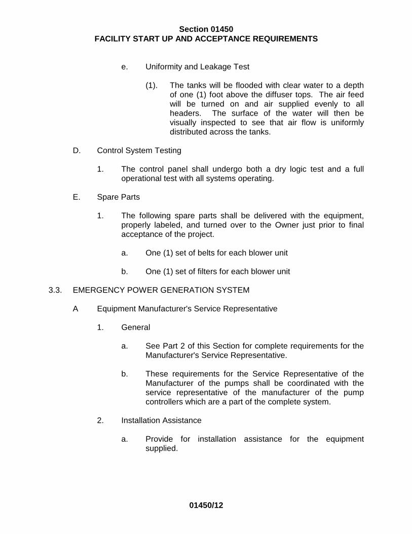
D. Control System Testing
1. The control panel shall undergo both a dry logic test and a full operational test with all systems operating.
E. Spare Parts
1. The following spare parts shall be delivered with the equipment, properly labeled, and turned over to the Authority just prior to final acceptance of the project.
a. A complete replacement pump shaft seal assembly shall be
furnished with each lift station. The spare seal shall be packed in a suitable container and shall include complete installation instructions.
3.2. EQUALIZATION TANK/ AERATION SYSTEM TESTING
A Equipment Manufacturer's Service Representative
1. General
a. See Part 2 of this Section for complete requirements for the
Manufacturer's Service Representative.
b. These requirements for the Service Representative of the Manufacturer of the pumps shall be coordinated with the service representative of the manufacturer of the pump controllers which are a part of the complete system.

Section 01450 FACILITY START UP AND ACCEPTANCE REQUIREMENTS
01450/9
2. Installation Assistance
a. Provide for installation assistance for the equipment supplied.
3. Aeration System Startup and Balancing Assistance
a. Provide for process startup and/or process stabilization and
balancing assistance for the equipment supplied.
4. Operating Instructions and/or Operator Training
a. An additional two (2) trips not less than one (1) day per trip shall be provided for operation assistance of the equipment supplied by the pump manufacturer.
b. Provide for two (2) eight (8) hour working days total to
instruct Plant Operators for the equipment supplied. The training period will be integrated with overall plant training. See Part 2 of this Section for additional information.
c. An additional two (2) trips not less than one (1) day per trip
shall be provided for operation assistance of the equipment supplied.
c. An additional trip of not less than one (1) day shall also be
provided for operation assistance of the equipment supplied six (6) months following final completion of the Project.
e. A day trip is defined as eight (8) onsite working hours.
B Aeration Blower Testing
1. All aeration blowers shall be required to meet factory performance
tests within the following tolerances when operating at rated speed and rated capacity as per the manufacturer’s specifications.
2. Final performance curves shall be based on actual factory
performance test. All test data shall be available to the Engineer, if required.

Section 01450 FACILITY START UP AND ACCEPTANCE REQUIREMENTS
01450/10
C. Equalization Tank Testing
1. All new steel tanks shall be tested for water tightness by filling with water and holding the water in the tanks at least seventy-two (72) hours. The Builder/ Developer shall furnish either potable or utility water for all tanks to be tested. All evident leaks resulting from this testing shall be repaired and the tank retested for water tightness.
2. All concrete work must be inspected by the Engineer. 3. All rebar installation must be inspected prior pouring of any conrete
wall or floor structure. D. Aeration System Testing
1. Pre-Start-Up Inspection
a. When construction has been completed, the Manufacturer's
Service Representative and the Engineer will perform a pre-start-up inspection of the system to include the following:
(1). Relative unit elevations will be verified.
(2). All ductile iron flange and PVC weld connections will
be inspected.
(3). Air flow in each header and lateral will be checked.
(4). All mounting bolts will be checked.
(5). All units will be checked for possible construction damage.
b. All components of the aeration system shall be given an
operational test of all equipment to check for excessive vibration, for leaks in all piping or seals, for correct operation of the pump priming and all auxiliary equipment.

Section 01450 FACILITY START UP AND ACCEPTANCE REQUIREMENTS
01450/11
2 Acceptance Testing and Inspection
a. General
(1). When the installation is ready for inspection, the Builder/ Developer and Engineer shall agree upon a time for Acceptance Testing and Inspection. The Builder/ Developer shall then carry out the tests and inspections to be witnessed by the Engineer.
b. Mounting Tests
(1). Support and tie-down provisions of the diffuser piping
shall be tested to insure that they have a margin of safety of 10 against calculated buoyant forces. The support and tie-down system of the header piping shall be tested to insure that they have a margin of safety of 2 against calculated buoyant forces.
(2). Upon installation of the supports and prior to
installation of piping, all of the supports of each type shall be tested by the Builder/ Developer with no less than 10% of the supports of each type, chosen at random to be witness tested by the Engineer. Each support chosen for test shall be attached to a lever which shall be placed on a fulcrum. A static load shall be applied to the opposite end producing a vertical extracting force on the support tie-down equal to either 10 times or 2 times the calculated maximum buoyant force to which the support tie-downs will be subjected in normal operation as detailed above.
c. Inspection of Piping
(1). The piping shall be inspected for proper joints,
supports and tie downs, end plugs and drain relief valves.
d. Level Test
(1). The tanks shall be flooded with clear water to the top
of the diffusers. The level of the diffusers shall then be checked to see that they are at the same elevation within +1/4 inch.
Section 01450 FACILITY START UP AND ACCEPTANCE REQUIREMENTS
01450/12
e. Uniformity and Leakage Test
(1). The tanks will be flooded with clear water to a depth of one (1) foot above the diffuser tops. The air feed will be turned on and air supplied evenly to all headers. The surface of the water will then be visually inspected to see that air flow is uniformly distributed across the tanks.
D. Control System Testing
1. The control panel shall undergo both a dry logic test and a full operational test with all systems operating.
E. Spare Parts
1. The following spare parts shall be delivered with the equipment, properly labeled, and turned over to the Owner just prior to final acceptance of the project.
a. One (1) set of belts for each blower unit b. One (1) set of filters for each blower unit
3.3. EMERGENCY POWER GENERATION SYSTEM
A Equipment Manufacturer's Service Representative
1. General
a. See Part 2 of this Section for complete requirements for the
Manufacturer's Service Representative.
b. These requirements for the Service Representative of the Manufacturer of the pumps shall be coordinated with the service representative of the manufacturer of the pump controllers which are a part of the complete system.
2. Installation Assistance
a. Provide for installation assistance for the equipment
supplied.

Section 01450 FACILITY START UP AND ACCEPTANCE REQUIREMENTS
01450/13
3. Generator Startup and Balancing Assistance
a. Provide for unit startup and balancing assistance for the equipment supplied.
4. Operating Instructions and/or Operator Training
a. An additional three (3) trips not less than one (1) day per trip
shall be provided for operation assistance of the equipment supplied by the pump manufacturer.
b. Provide for two (2) eight (8) hour working days total to
instruct Plant Operators for the equipment supplied. The training period will be integrated with overall plant training. See Part 2 of this Section for additional information.
c. An additional two (2) trips not less than one (1) day per trip
shall be provided for operation assistance of the equipment supplied.
d. An additional trip of not less than one (1) day shall also be
provided for operation assistance of the equipment supplied six (6) months following final completion of the Project.
e. A day trip is defined as eight (8) onsite working hours.
B Generator Testing
1. Perform a field test in the presence of the Engineer and a factory
trained representative of the engine supplier to show that the set will operate as specified under full load.
2. On completion of the installation, have a factory-trained
representative of the engine supplier perform the initial start-up and explain the operating instructions and maintenance procedure to the Owner's operating personnel.
C. Fuel Oil
1. After all testing and start-up and prior to final acceptance, fill the
fuel oil storage tank with No. 2 fuel oil.
D. Control System Testing
1. The control panel shall undergo both an off-line logic test and a full operational test with all systems operating.

Section 01450 FACILITY START UP AND ACCEPTANCE REQUIREMENTS
01450/14
2. The system shall be tested to document that the automatic transfer
switch will function as a result of a complete power failure at the site.
3.4. FLOW EQUALIZATION CONTROL SYSTEMS
A Equipment Manufacturer's Service Representative
1. Installation Assistance
a. Provide the services of a qualified factory engineer to
supervise the installation, to test and make any adjustments required, and to place the completed system in operation.
b. Extreme care shall be taken in adjusting and tuning
controller PID functions to the process loop dynamic characteristics, and in programming of digital program generators for correct cyclic operation per project requirements.
2. System Operation Training
a. The Builder/ Developer shall have the instrumentation
supplier provide a factory trained engineer to instruct the Owner's operating personnel in the use, operation, care, and maintenance of the instrumentation panels and accessories.
b. The training shall be conducted on-site and be presented in
a manner to impart thorough understanding of the systems and equipment provided.
c. The training shall be given to those Owner personnel, who
shall be responsible for the facility operation during each work shift. The personnel shall sign a certificate, presented by the Builder/ Developer, that they have been trained on the plant equipment and that they thoroughly understand the use, operation care and maintenance of the equipment.
d. When the Owner is ready to have his personnel trained, the
Builder/ Developer will be so notified by the Engineer. The Builder/ Developer will then ensure that the manufacturer's representatives are available on-site to conduct the required training.

Section 01450 FACILITY START UP AND ACCEPTANCE REQUIREMENTS
01450/15
a. Provide for two (2) eight (8) hour working days to instruct Plant Operators for the equipment supplied. The Owner will require the Builder/ Developer to integrate such training with the overall facility training program developed by the Builder/ Developer and approved by the Engineer.
b. Also provide two (2) eight hour working days specifically to
instruct Plant Operators in adjusting of microprocessor based controllers and programming of digital program generators.
c. An additional two (2) trips not less than one (1) day per trip
shall be provided for operation assistance of the equipment supplied.
B Factory Tests
1. Testing of Individual Components
a. Each item of equipment shall be fully factory inspected and tested for function, operation and continuity of circuits.
2. Full System Tests
a. An operation check of the entire system shall be performed
by the instrumentation supplier at his factory. Power and manually adjustable measurement and control circuits shall be connected to the central control for simulating the functions specified within the Specification section.
b. The Engineer shall be notified at least ten (l0) days in
advance of any factory systems tests and reserves the right to have its representatives in attendance.
C. FIELD TESTING AND ACCEPTANCE
1. Analog Instrument Calibration
a. All analog instruments shall be installed such that taps and parts, etc are available for in-place calibration and test without removal. For those instruments where such in situ calibrations are not feasible (e.g. pH immersion electrodes, etc.), other calibration methods shall be provided subject to review by the Engineer.

Section 01450 FACILITY START UP AND ACCEPTANCE REQUIREMENTS
01450/16
b. Field calibration shall be achieved using a minimum of five (5) points (0, 25, 50, 75, and 100 percent) for calibration. Additional points may be required by the Engineer for non-linear instruments.
c. Standard calibration mixtures (e.g. pH buffer, gas mixtures,
etc.) shall be provided as required for start-up. Sufficient quantities shall be provided to allow calibration checks during the guarantee period as required by the Equipment Manufacturer's recommendations.
d. Other elements such as controllers, final operators, etc. shall
be exercised to demonstrate correct operation.
2. Operation Simulation
a. All conditions of operation shall be simulated to demonstrate that each system operates properly.
3. System Acceptance
a. The system will not be accepted until all equipment satisfies
the acceptance test requirements. The complete system shall operate continuously during an acceptance test period of not less than thirty (30) days with no down-time of the complete system resulting from failure of hardware. Down-time of the system or portions of the system resulting from the following causes will not be considered system failures:
(1). Down-time resulting from an outage of the main
power supply provided that automatic shutdown and restart of the system satisfies the requirements of these Specifications.
(2). Down-time of a portion of the system resulting from
failure of a communications channel provided that the system operated as specified under this condition.
(3). Down-time caused by operator error.

Section 01450 FACILITY START UP AND ACCEPTANCE REQUIREMENTS
01450/17
4. Markings
a. The panel shall have a nameplate securely affixed in a conspicuous place on which is marked the manufacturer's name and address.
b. All panel mounted items shall be clearly identified with a
nameplate which indicates its function. Front of panel mounted equipment shall be identified with engraved nameplates with 2 color lamination, fastened with stainless steel drive pins.
c. All field wiring terminating in control panels shall be identified
by marked sleeving or other acceptable method, to indicate signal source or wire function.
5 Maintenance
a. Corrective maintenance shall be performed only by a factory trained service technician specifically trained for servicing the types of equipment furnished under this Project.

Section 01450 FACILITY START UP AND ACCEPTANCE REQUIREMENTS
01450/18
PART 4 - EQUIPMENT CERTIFICATION
EQUIPMENT CERTIFICATION
Owner: Date: _____________________ Project:_______________________________________________________________ Contract No.: For the Work performed by
(Contractor or Builder/ Developer) Specification Section No: Title: _____________________________________ On , (Date) (Name(s) of Service Representative(s)) representing _____________________________________________________ visited (Equipment Manufacturer) ________________________________________________________________ for the
(Name of Project) purpose of certifying the installation and operation of: Equipment Name Tag No. I/we certify that the installation and operation of the above equipment, except as noted below, is in complete compliance with the Manufacturer's recommendations and Engineer's requirements. The installation and operation of the following equipment does not Comply with

Section 01450 FACILITY START UP AND ACCEPTANCE REQUIREMENTS
01450/19
the Manufacturer's recommendations and Engineer's requirements. Equipment Tag No. Reason for Non Certification Signature Title Company
END OF SECTION

Section 01500 TEMPORARY FACILITIES AND CONTROLS
UPPER SAUCON TOWNSHIP June 1, 2014
01500/1
PART 1 GENERAL 1.1 SCOPE
A. The Developer/Builder is referred to conditions and requirements given in various Sections of these Specifications
1.2 OCCUPYING PRIVATE LAND
A. Written consent from the proper parties shall be obtained by the Developer/Builder prior to entering or occupying with men, tools, materials or equipment any land other than his property for any purpose related to his performance of the Work.
1.3 PROTECTION OF EXISTING UTILITIES
A. The Developer/Builder shall conduct his operations and take all special precautions necessary to protect equipment, utility lines, roadways and subsurface, submerged and overhead facilities which are to remain in place and undisturbed by his operations under the work. The Developer/Builder shall immediately notify the owner of the facilities or areas which are disturbed, damaged or injured as a result of the Developer/Builder's operations, and determine the proper method of replacing or repairing the affected facilities at least to the conditions which existed prior to the Developer/Builder's operations. The Developer/Builder shall, at his own expense, replace, repair or restore the affected facilities or areas to their original condition or shall reimburse the owner of said facilities or areas for such expenses as the Township accrues in performing the work.
1.4 INTERFERENCE WITH/AND PROTECTION OF STREETS
A. The Developer/Builder shall not close or obstruct any portion of a street, road or private way without obtaining permits from the proper authorities. If any street or private way shall be rendered unsafe by the Developer/Builder operations, he shall make such repairs or provide such temporary ways or guards as shall be acceptable to the appropriate authority.
B. The Developer/Builder shall assume full responsibility for the maintenance
and restoration of those roadways within the construction area and also those roadways on which equipment must operate to reach the construction area.

Section 01500 TEMPORARY FACILITIES AND CONTROLS
01500/2
C. Streets, roads, private ways and walks not closed shall be maintained passable by the Developer/Builder at his expense, and the Developer/Builder shall assume full responsibility for the adequacy and safety of provisions made.
D. The Developer/Builder shall, 48 hours in advance of closing any street,
notify in writing, the Township Police and Fire departments, Southern Lehigh School District's transportation coordinator, Upper Saucon Township Manager, and the Township's Engineer. He shall cooperate with the Township Police Department in the establishment of alternate routes and, at his own expense, shall provide adequate, plainly marked detour signs. The signs shall be as required by the agency that has jurisdiction over the roadway.
E. For the proper control of traffic, the Developer/Builder shall provide an
adequate number of persons employed at his own expense.
F. The Developer/Builder shall immediately report in writing, giving full details, to the Township Police Department all accidents which arise out of or in connection with the performance of the Work, whether on or adjacent to the site, which cause death, personal injury or property damage. In addition, the accident shall be reported immediately by telephone or messenger to the Township. If a claim is made or suit is filed by anyone against the Developer/Builder on account of any accident, the Developer/Builder shall promptly report the facts in writing to Upper Saucon Township, giving full details of the claim.
1.5 DUST CONTROL
A. During the progress of the work, the Developer/Builder shall conduct his operations and maintain the area of his activities so as to minimize the creation and dispersion of dust.
1.6 SANITARY
A. The Developer/Builder shall provide, maintain and remove when no longer required, an adequate number of temporary, prefabricated, chemical-type toilets with proper enclosures for the use of workmen and women of all trades during construction. Locate toilets where necessary. When connected to public water and public sewer, meet all code requirements and take precautions to prevent freezing.
B. The Developer/Builder shall keep toilets clean and supplied with toilet
paper at all times. Comply with all local and state health requirements and sanitary regulations.

Section 01500 TEMPORARY FACILITIES AND CONTROLS
01500/3
1.7 WATER
A. The Developer/Builder shall make necessary arrangements and supply all potable and non-potable water required during entire construction period.
END OF SECTION

Section 02110 CLEARING AND GRUBBING
UPPER SAUCON TOWNSHIP June 1, 2014
02110/1
PART 1 GENERAL 1.1 SCOPE
A. Description of Work
1. Provide all labor, material and equipment to perform all clearing and grubbing as shown on the Approved Plans and as specified herein.
B. Related Work Specified Elsewhere
1. Removal of peat, moss, lignite and vegetable matter below ground
other than as specified in this section and Section 02220, EARTHWORK FOR UTILITIES.
2. Stripping and stockpiling topsoil; Section 02220, EARTHWORK
FOR UTILITIES. 1.2 PROTECTION
A. Streets, roads, adjacent property and other works to remain shall be protected throughout the Work .
B. Existing trees, shrubs and bushes
1. Trees shall be protected by fencing, barricades, or wrapping as
may be required.
2. Shrubs and bushes shall be protected by fences or barricades as may be required.
3. Shallow-rooted plants shall be protected by fences, barricades or
ground cover protection as may be required at ground surface under and in some cases outside the spread of branches .
1.3 REQUIREMENTS OF REGULATORY AGENCIES
A. Federal, State and Local laws and code requirements shall control the disposal of trees and shrubs.

Section 02110 CLEARING AND GRUBBING
02110/2
PART 2 PRODUCTS 2.1 MATERIALS
A. Materials necessary for the clearing and grubbing operation shall be at the Contractor's option.
PART 3 EXECUTION 3.1 GENERAL
A. When working within temporary or permanent Rights-of-Way, use every means possible to protect from injury and damage, all property, including trees, shrubbery, lawns, fences, buildings, walls, roads, water courses, natural features or any improvements thereto, which may exist. Do not willfully or maliciously injure or destroy trees, shrubs or vegetation and do not remove or cut them without permission of the Township or the rightful property owner.
B. All operations must be confined to the width of the Rights-of-Way
secured. All damage done to any property regardless of ownership resulting from the Developer/Builder's negligence shall be repaired without charge to the satisfaction of the Township with the exception of those items (trees, shrubbing, etc.) that must be removed for construction and have been agreed upon beforehand, in writing, between the Developer/Builder and Property Owner.
3.2 CLEARING
A. Limits of clearing shall be within the Rights-of-Way, to limits shown on the Approved Plans.
B. Trees in construction zones or Rights-of-Way shall not be removed
or altered in any way until they are first inspected and tagged by the Property Owner and/ or the appropriate Township Official.
1. No trees shall be removed within the construction zone or
Rights-of-Way except the following:
a. Trees within an excavated area such as a footing or trench.
b. Trees whose root system will be destroyed by the
excavation.

Section 02110 CLEARING AND GRUBBING
02110/3
c. Trees that interfere with the movement of the Developer/Builder's equipment with the approval of the Property Owner. Any trees that interfere with the movement of the Developer/Builder's equipment shall be reviewed by the Township before they are removed.
C. All trees bordering any construction zone or right-of-way shall be
protected by acceptable methods. Trees damaged by the Developer/Builder will be either repaired or replaced as determined by the Owner or his Representative at the Developer/Builder's expense.
D. Vegetation within the areas to be cleared, which may be
designated to be saved by the Township shall be left standing and uninjured. Remove trees, sapling, shrubs, bushes, vines and undergrowth within the limits of clearing to the heights above ground given in the following table:
1. Trees over 6-inches in diameter: 12 inches
2. Shrubs, saplings, bushes and trees under 6 inches in
diameter: 3 inches
3. Vines and undergrowth: 2 inches
F. Stumps
1. Stumps required to be removed shall be to a depth of 18 inches. This depth shall be measured from the existing ground surface or the proposed finished grade, whichever is the lower.
2. Engineering requirements shall control removal of stumps under
fills, foundations, or any construction in contact with the stumps.

Section 02110 CLEARING AND GRUBBING
02110/4
3.3 GRUBBING
A. Limits of grubbing shall coincide with the limits of clearing.
B. Remove all stumps, roots over 4-inches in diameter, and matted roots within the limits of grubbing to the depths below. Such depths shall be measured from the existing ground surface or the proposed finish grade whichever is the lower.
1. Footings 18 inches
2. Walks 12 inches
3. Roads 18 inches
4. Parking Areas 12 inches
5. Lawn Areas 8 inches
6. Fills 12 inches
3.4 TRIMMING OF TREES
A. When required, with the Property Owner's prior written approval, trees shall be trimmed to remove branches or roots which interfere with construction or traffic. Paint all cut branches and roots with wound paint as recommended for the application.
B. No trees or vegetation shall be removed or altered within PennDOT's
rights-of-way unless a separate specific permit is obtained from the District Roadside Development Specialist authorizing such removal or alteration.
3.5 SALVAGE
A. Material which is to be salvaged, as a result of the clearing operations, shall include the following items which are to be turned over to the property owner if the property owner so desires.
1. Logs over 12 inches, butt diameter
2. Branches over 6 inches, butt diameter
3. Parts suitable for use as mulch

Section 02110 CLEARING AND GRUBBING
02110/5
4. Live plants suitable for replanting
B. Cut logs and branches into cordwood, 2 feet 6 inches in length and store on site where acceptable to the property owner.
C. All salvageable material not desired by the property owner shall be
removed as part of the Work. D. Brush, branches and material unsuitable for cordwood shall be run
through a chipper to produce mulch. E. Live plants which are requested to be turned over to the Property Owner
shall be properly balled to protect the root system. 3.6 DISPOSAL
A. Burning of materials on the site will not be permitted.
B. Removal:
1. Material to be removed shall be removed from the site daily as it accumulates.
2. Should the Developer/Builder elect to continue work beyond normal
working hours, material to be removed shall not be allowed to accumulate for more than 48 hours.
3. Disposal of surplus material within PennDOT's rights-of-way is
prohibited. All surplus material must be disposed of as the work progresses and shall not be stored on PennDOT's rights-of-way for future removal.
END OF SECTION

Section 02220 EARTHWORK FOR UTILITIES
UPPER SAUCON TOWNSHIP June 1, 2014
02220/1
PART 1 - GENERAL 1.1 SCOPE
A. Description of Work
1. Provide all labor, material and equipment to excavate pipe trenches and backfill after the installation of the pipe, all in accordance with the Approved plans and as specified herein.
B. Related Work Specified Elsewhere
1. Clearing, Section 02110, CLEARING AND GRUBBING
2. Rock Excavation, Section 02230, ROCK EXCAVATION
3. Piping, Section 02551, GRAVITY SANITARY SEWERS AND
APPURTENANCES
4. Piping, SECTION 02980, PIPELINE CROSSINGS UNDER STATE HIGHWAY
5. Concrete, Section 03301, CAST-IN-PLACE CONCRETE
1.2 LINES AND GRADES
A. Grades
1. Pipes shall be placed true to the lines and grades shown on the Approved Plans. The grade shown on the profile is the invert to which the Work must conform. Work not conforming to the lines and grades shall be corrected by the Developer/Builder.
2 The Developer/Builder is responsible for maintaining the line and
grade. The pipe shall be checked at each manhole to assure that it is on the correct line and grade.

Section 02220 EARTHWORK FOR UTILITIES
02220/2
B. Locations of Lines
1. The Township reserves the right to make changes in lines and grades of pipe lines and in locations of pipes and manholes when such changes may be necessary or advantageous.
C. Sewer Pipe Cover
1. All sanitary sewer main or lateral piping must have a minimum of 4 feet of cover over the top of the sewer pipe.
1.3 CLEARING
A. Clearing of the site is described in Section 02110, CLEARING AND GRUBBING.
1.4 TRENCHING REGULATIONS
A. In open trenching on State, County, and Township highways, the Developer/Builder shall be governed by the conditions, restrictions and regulations made by the State Highway Department, the County Commissioners, and the Upper Saucon Township Board of Supervisors. All such regulations shall be in addition to the ones set down in these Specifications.
PART 2 - PRODUCTS 2.1 BACKFILLING MATERIALS
A. Compaction
1. Backfill shall be capable of being compacted to not less than 95% of maximum dry density as determined by ASTM D 1557.
B. Suitable Materials (Non-Traffic Areas)
1. Suitable Material is defined as excavated material from the trench
or materials from other sources which are free from particles larger than 6 inches nominal diameter and other deleterious materials (e.g. wood, vegetation, trash, debris, etc.).

Section 02220 EARTHWORK FOR UTILITIES
02220/3
C. Select Backfill (Crushed Stone)
1. Select backfill shall be as shown on the table below, not washed, with fines present to stabilize it in the trench. If amount of fines is insufficient, then stone screenings shall be added to extent required to stabilize it in the trench.
Square Mesh Sieve Size Percent Passing by Weight 1 in. 100 3/4 in. 52-100 3/8 in. 36-70 No. 4 24-50 No. 16 10-30 No. 200 0-10
D. Concrete
1. Concrete used for cradles, thrust blocks, or encasement shall be Class B concrete as specified in Section 03301, CAST-IN-PLACE CONCRETE. Tests of concrete for this usage are waived.
2.2 SEDIMENT CONTROL DEVICE
A. Description
1. This work shall consist of furnishing, placing and removing the sediment control device as required on the contract drawings. The sediment control device shall be a DIRTBAG pumped-silt control system as marketed by ACF Environmental, Inc of Richmond, VA or equal.
2. The unit will be sized based on the output capacity of the
Developer/Builder’s dewatering pumping system.
B. Materials
1. The sediment control device shall be a nonwoven bag which is sewn with a double needle machine using high strength thread.
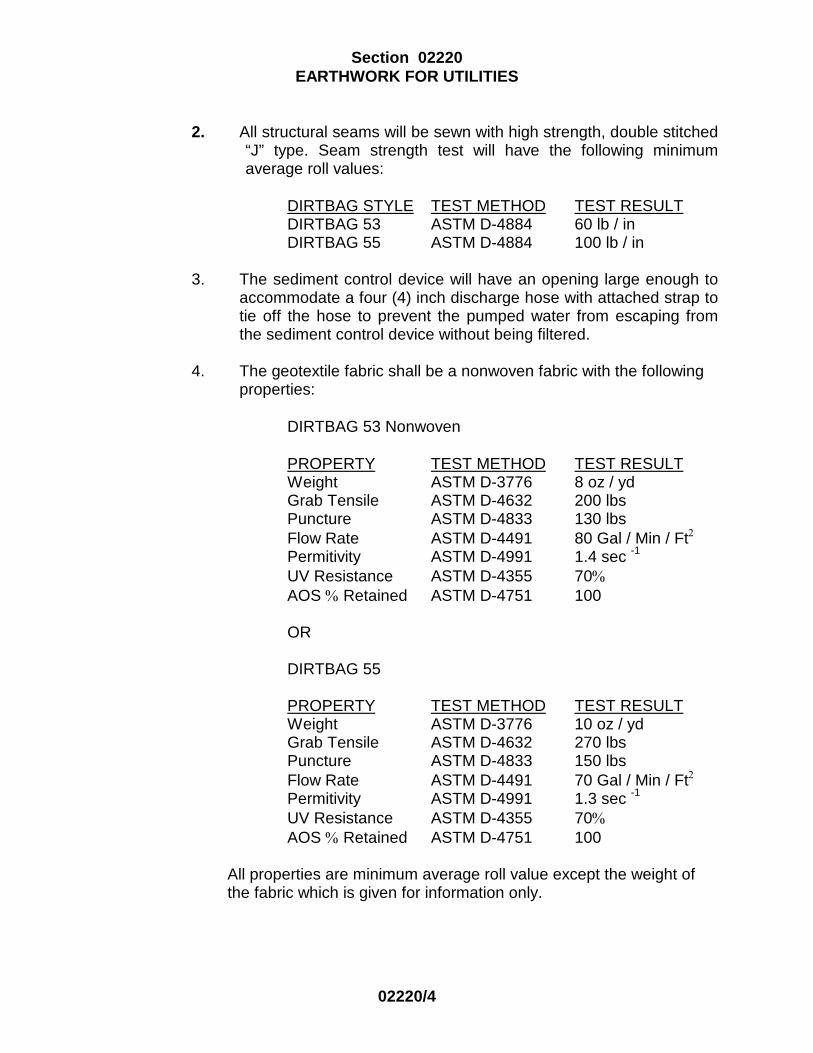
Section 02220 EARTHWORK FOR UTILITIES
02220/4
2. All structural seams will be sewn with high strength, double stitched “J” type. Seam strength test will have the following minimum average roll values:
DIRTBAG STYLE TEST METHOD TEST RESULT DIRTBAG 53 ASTM D-4884 60 lb / in DIRTBAG 55 ASTM D-4884 100 lb / in
3. The sediment control device will have an opening large enough to
accommodate a four (4) inch discharge hose with attached strap to tie off the hose to prevent the pumped water from escaping from the sediment control device without being filtered.
4. The geotextile fabric shall be a nonwoven fabric with the following
properties: DIRTBAG 53 Nonwoven PROPERTY TEST METHOD TEST RESULT Weight ASTM D-3776 8 oz / yd Grab Tensile ASTM D-4632 200 lbs Puncture ASTM D-4833 130 lbs Flow Rate ASTM D-4491 80 Gal / Min / Ft2
Permitivity ASTM D-4991 1.4 sec -1
UV Resistance ASTM D-4355 70% AOS % Retained ASTM D-4751 100 OR
DIRTBAG 55 PROPERTY TEST METHOD TEST RESULT
Weight ASTM D-3776 10 oz / yd Grab Tensile ASTM D-4632 270 lbs Puncture ASTM D-4833 150 lbs Flow Rate ASTM D-4491 70 Gal / Min / Ft2 Permitivity ASTM D-4991 1.3 sec -1
UV Resistance ASTM D-4355 70% AOS % Retained ASTM D-4751 100 All properties are minimum average roll value except the weight of
the fabric which is given for information only.

Section 02220 EARTHWORK FOR UTILITIES
02220/5
2.3 PIPE BEDDING MATERAL
1. The pipe bedding material shall be stone as defined in PennDOT Section 703.2 (408/2000, Change No. 8).
2. The pipe bedding material shall conform to Type B (Coarse
Aggregate Quality Requirements) Coarse Aggregate as per PennDOT Chapter 703 (408/2000, Change No. 8) Table B.
3. Pipe bedding material shall be ASSHTO #8 as shown on Table C
(Size and Grading Requirements for Coarse Aggregates) of PennDOT Chapter 703 (408/2000, Change No. 8). The stone shall be washed with no fines present.
PART 3 - EXECUTION 3.1 EXCAVATION
A. General
1. Perform all excavation of every description and of whatever substances encountered to the depth shown on the Approved Plans.
2. All waste materials, including unsatisfactory soils, excavated
material not used for backfill, trash, and debris, shall be removed from the site of the Work by the Developer/Builder.
3. All excavation, unless otherwise authorized by the Township , shall
be made by open cut. Side walls of trenches shall be kept vertical and shall be properly sheeted and braced.
4. When applicable, coupling holes of proper size shall be excavated
to insure pipe resting for its entire length upon the bottom of the trench.
5. Where damage is liable to result from withdrawing sheeting, the
sheeting shall be left in place. Sheeting shall be left in place only when agreed to or requested by the Township.
6. Care shall be taken not to excavate below the depth specified.
7. The Developer/Builder will coordinate with property owners
locations for stockpiling top soil removed as a result of excavation of the sewer piping.

Section 02220 EARTHWORK FOR UTILITIES
02220/6
B. Rock
1. Rock excavation, when needed, shall be done in accordance with Section 02230, ROCK EXCAVATION.
C. Excavation Below Grade
1. Where the bottom of the trench, by mistake of the
Developer/Builder, is taken out to a greater depth than specified for a given pipe bedding the trench shall be brought back to grade as follows:
a. When the pipe was to be supported by crushed stone
encasement, or concrete encasement. the over-excavation shall be filled with crushed stone so as to comply with the requirements for foundation.
2. Refilling with earth to bring the bottom of the trench to the proper
grade will not be permitted.
D. Blasting
1. Blasting, when needed, shall be done in accordance with the Specification For Blasting in Section 02230, ROCK EXCAVATION.
3.2 EXCAVATION NEAR EXISTING STRUCTURES
A. All utility lines shall be located on the ground with appropriate locating equipment well ahead of the work at all times. All such locations shall be plainly marked by coded paint symbols on pavement or by marked stakes in the ground. Such locations shall be established at least 50 feet in advance of all trench excavation. Locating and/or marking procedures dictated by Pennsylvania Act 38 shall take precedence over those indicated herein.
B. As the excavation approaches pipes, conduits or other underground
structures, digging by conventional trenching machine methods shall be done with extreme care.
C. When excavating within 2 feet (vertical or horizontal) of utility lines the
Developer/Builder shall use the manual method of excavation. At no time will conventional trenching equipment be permitted under these conditions.

Section 02220 EARTHWORK FOR UTILITIES
02220/7
D. Excavation near structures will not be allowed closer to the structure than
the depth of the excavation below the bottom of the foundation without shoring the excavation with sheeting.
E. The Developer/Builder shall carefully protect from disturbance and
damage all land monuments and property markers until an authorized agent of the disturbed or damaged item has witnessed or otherwise referenced their locations. These monuments and/or markers shall then only be removed when authorized by the Township. Monuments and/or markers shall be reinstalled by a Registered Professional Surveyor, who is retained and paid by the Developer/Builder to the satisfaction of the property owner or agent.
3.3 PROTECTION OF EXISTING STRUCTURES
A. All existing pipes, poles, wires, fences, curbings, property-line markers and other structures which must be preserved in place without being temporarily or permanently relocated, shall be carefully supported and protected from damage by the Developer/Builder.
B. In case of damage to any structure, the Developer/Builder shall notify the
appropriate party so that proper steps may be taken to repair any and all damage done. If the owner of the structure wishes to make his own repairs, the Developer/Builder shall reimburse the owner of the structure for all the time and materials required to make the repairs.
C. When the owners of the damaged structures do not wish to make the
repairs themselves, all damage shall be repaired by the Developer/Builder, or, if not promptly repaired by him, the Township shall have the repairs made at the expense of the Developer/Builder.
D. All utility services shall be supported by suitable means so that the
services shall not fail when tamping and settling occurs.

Section 02220 EARTHWORK FOR UTILITIES
02220/8
3.4 CARE AND RESTORATION OF PROPERTY
A. Excavating machinery shall be operated with care to prevent damage to existing structures, paving and/or wires.
B. The Developer/Builder must exercise care not to damage paving, curb,
inlets, sidewalks, etc., beyond the limits of his work. Any damages to areas shall be replaced in kind by the Developer/Builder.
C. The restoration of existing property or structures shall be done as
promptly as practicable and shall not be left until the end of the construction period.
D. The Developer/Builder will be responsible for restoration of all facilites
located outside of the construction areas which were damaged as a result of construction activities.
3.5 TRENCHING
A. Trenches shall be dug to the depth required by the Approved Plans adding, however, to such depths the thickness of the pipe and the required bedding. The width of the trench shall be as described in previous Paragraph 3.1, A. A recess sufficiently large enough to receive the couplings, where applicable, and to permit making the joints, shall be cut out of the bottom of the trench.
B. During installation, upon encountering quicksand or a wet spongy
material, the Developer/Builder shall determine the actual depth of the soft material. Once the depth of the soft material has been determined, one of the following methods of construction shall be used
1. Installation by the quicksand excavation method
2. Crushed stone foundation
3. Concrete encasement

Section 02220 EARTHWORK FOR UTILITIES
02220/9
3.6 BORING/ JACKING OPERATIONS
A. Details for all boring and/ or jacking operations shall be included on the Approved Plans.
B. Boring and/ or jacking operations shall be limited to the areas depicted on
the Approved Plans. C. Only ductile iron pipe will be used for sanitary sewers in areas requiring
boring/ jacking operatiuons unless authorized in writing by the Authority Engineer.
3.7 WETLANDS/ STREAM CROSSING OPERATIONS
A. Details for all stream crossing operations shall be included on the Approved Plans.
B. Stream crossing operations shall be limited to the areas depicted on the
Approved Plans. C. Only ductile iron pipe will be used for sanitary sewers in areas requiring
stream crossing operatiuons unless authorized in writing by the Authority Engineer.
D. All stream crossings must include concrete encasement that extends at
least 50 ft from all edges of the stream or delineated wetland area.
E. All wetland/stream crossings must be designed to meet current Pennsylvania Department of Environmental Protection requirements.
F. The Developer/ Builder must obtain all necessary regulatory permits for
any wetlands/stream crossing operation prior to starting work. The Developer/ Builder must provide written confirmation from Pennsylvania Department of Environmental Protection for cases where regulatory permits are not required for crossings.
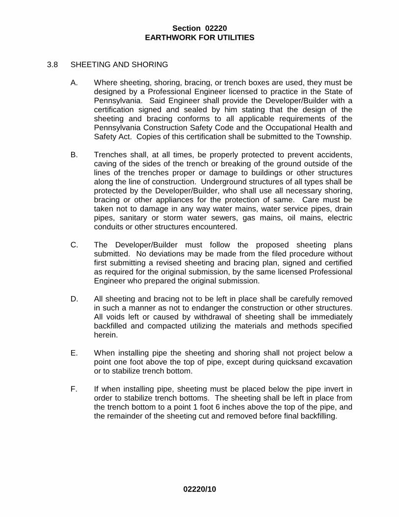
Section 02220 EARTHWORK FOR UTILITIES
02220/10
3.8 SHEETING AND SHORING
A. Where sheeting, shoring, bracing, or trench boxes are used, they must be designed by a Professional Engineer licensed to practice in the State of Pennsylvania. Said Engineer shall provide the Developer/Builder with a certification signed and sealed by him stating that the design of the sheeting and bracing conforms to all applicable requirements of the Pennsylvania Construction Safety Code and the Occupational Health and Safety Act. Copies of this certification shall be submitted to the Township.
B. Trenches shall, at all times, be properly protected to prevent accidents,
caving of the sides of the trench or breaking of the ground outside of the lines of the trenches proper or damage to buildings or other structures along the line of construction. Underground structures of all types shall be protected by the Developer/Builder, who shall use all necessary shoring, bracing or other appliances for the protection of same. Care must be taken not to damage in any way water mains, water service pipes, drain pipes, sanitary or storm water sewers, gas mains, oil mains, electric conduits or other structures encountered.
C. The Developer/Builder must follow the proposed sheeting plans
submitted. No deviations may be made from the filed procedure without first submitting a revised sheeting and bracing plan, signed and certified as required for the original submission, by the same licensed Professional Engineer who prepared the original submission.
D. All sheeting and bracing not to be left in place shall be carefully removed
in such a manner as not to endanger the construction or other structures. All voids left or caused by withdrawal of sheeting shall be immediately backfilled and compacted utilizing the materials and methods specified herein.
E. When installing pipe the sheeting and shoring shall not project below a
point one foot above the top of pipe, except during quicksand excavation or to stabilize trench bottom.
F. If when installing pipe, sheeting must be placed below the pipe invert in
order to stabilize trench bottoms. The sheeting shall be left in place from the trench bottom to a point 1 foot 6 inches above the top of the pipe, and the remainder of the sheeting cut and removed before final backfilling.

Section 02220 EARTHWORK FOR UTILITIES
02220/11
3.9 QUICKSAND EXCAVATION
A. Where quicksand excavation is encountered, the Developer/Builder shall drive either tight tongue and groove wooden sheet piling or steel sheet piling to a depth which will effectively cut off the flow of sand. Well points and other methods shall then be used to dewater the trench. Excavation and construction shall follow as rapidly as possible thereafter. A satisfactory foundation must, however, be secured either by close tongue and groove planking held by piling or some other acceptable method. Where pipe is to be constructed through quicksand excavation, the trench shall be carried to a sufficient depth below the grade line to permit the pipe to be encased in concrete, on a 2-inch x 10-inch plank platform or cradle.
B. The Developer/Builder shall comply with the Section of the Specifications
for design of the sheet piling. 3.10 TRENCHING IN ADVANCE OF PIPE LAYING
A. The trench for the pipe lines shall not be opened for a distance of more than 100 feet at any one time. At no time will the Developer/Builder be permitted to leave the trench open at the end of a working day.
B. If concrete is to be installed for pipe encasement, longer lengths of trench
may be left open with the Township's approval, provided that:
1. All trenching regulations are met (refer to Paragraph 1.4, "Trenching Regulations")
2. All trenches are properly secured and protected.
C. During periods when precipitation is anticipated, all trenches shall be
completely backfilled at the completion of each workday and reopened the following workday. Under no circumstances shall any pipe trench be left open during a period of precipitation.

Section 02220 EARTHWORK FOR UTILITIES
02220/12
3.11 DEWATERING
A. Care should be taken to prevent surface water and subsurface/ groundwater from entering excavations.
B. All ground water in the trenches and any water which may get into them
from any cause whatsoever shall be pumped out so that the trench shall be dry during the period of pipe installation. Water shall not be permitted to reach concrete until the concrete has set sufficiently. All water pumped from the trenches shall be disposed of in compliance with the applicable local regulations of the appropriate governing body. The Developer/Builder shall provide a minimum of two pumps for each trench opened in wet ground, one operating and one standby. The standby pump shall be of a size that will replace the largest operating pump.
C. The Developer/Builder shall provide and place all necessary flumes or
other channels of adequate size to carry temporarily all streams, brooks, storm water or other water which may flow along or across the lines of the pipe line. All flumes or channels thus utilized shall be tight so as to prevent leakage into the trenches.
D. The Developer/Builder shall provide adequate control measures for
discharge of water from the dewatering operations to assure that all soil and erosion control measures are in accordance with Lehigh County Conservation District requirements.
E. Sediment Control Device
1. Install the Sediment Control Device on a slope. It should be placed
so the incoming water flows into the bag and will flow through the Sediment Control Device and then flow off the site without creating more erosion. The neck of the Sediment Control Device should be tied off tightly to stop the water from flowing out of the Sediment Control Device without going through the walls of the bag. To increase the surface area being used, Sediment Control Device may be placed on a gravel bed to allow water to flow in all directions.
2. The Sediment Control Device is considered full and should be
disposed when it is impractical for the bag to filter the sediment out at a reasonable flow rate and should be replaced with a new Sediment Control Device.
3. Disposal shall be the responsibility of the Developer/Builder. The
Sediment Control Device shall be removed from site to a proper disposal area.
Section 02220 EARTHWORK FOR UTILITIES
02220/13
3.12 PIPE BEDDING
A. General
1. Use caution to avoid contact between the pipe and compaction equipment. The tampers shall be hand or pneumatic of the proper size to operate between trench wall and pipe without damaging the pipe.
2. Do not use compaction equipment directly over the pipe while
placing the pipe bedding to insure that such equipment will not damage or disturb the pipe.
3. Pipe bedding shall, in all cases, extend up until 1 foot of cover has
been built up over the pipe.
B. Crushed Stone Encasement
1. All pipe shall be encased in stone, the trench shall be excavated to
the depth shown on the Construction Details. The stone shall be placed in the trench for its full width to uniformly support the pipe at the required line and grade. The Contractor must install pipe to assure that uniform line and grade are met.
2. Encasement material shall be spread in 4-inch layers and each
layer shall be manually spead until the required total depth of bedding has been achieved. The Contractor must assure that the pipe is properly chaulked during this process.
C. Concrete Encasement
1. Where specified or required in the field, the pipe shall be supported
by Concrete Encasement.

Section 02220 EARTHWORK FOR UTILITIES
02220/14
2. The trench shall be excavated to a minimum depth as shown on the Approved Plans. The excavated space shall then be completely filled with, and the entire pipe encased in concrete such that the encasement measures a minimum 1 foot above the top of the pipe. The total minimum width of the Concrete Encasement shall equal the width of trench excavation. Unless otherwise shown on the Drawings or specified herein, concrete shall be Class B in accordance with the requirements of Section 03301, CAST-IN-PLACE CONCRETE. Freshly poured concrete shall be protected from surface or subsurface water until it has sufficiently set. Backfill of the trench should not commence until 24 hours after placement of concrete.
3.13 FOUNDATION
A. Select Backfill- For Foundation
1. Where a suitable supporting soil or rock stratum occurs at a depth greater than required on the Approved Plans but less than 2 feet below the pipe or where moderately unstable soil conditions are encountered or where the trench is excavated below the specified depth or where required by the Township, the foundation shall be modified as follows:
a. Except in the case of over-excavation where no extra
excavation will be required, the trench shall be excavated to the depth necessary to reach the suitable supporting stratum. Select backfill shall be spread in layers of not more than 4-inches in base depth, and each layer shall be compacted with 20-pound hand or pneumatic tampers.
b. The foundation shall carry vertically from the supporting
stratum up to the required level depending on the pipe diameter and the type of bedding specified.
2. When the above method of stabilizing trenches with stone is
unfeasible, the Developer/Builder shall proceed as described in Paragraph when 3.9, QUICKSAND EXCAVATION.

Section 02220 EARTHWORK FOR UTILITIES
02220/15
3.14 BACKFILLING
A. General
1. After pipes have been inspected by the Township for alignment and bedding, the trench may be backfilled. Backfill operations shall not begin before the Township gives permission.
2. Backfill material shall be placed in uniform layers along the full
length and width of the trench either by hand or machine. Sufficient number of Developer/Builder's workers shall be available to spread the backfill in uniform layers.
3. Trash and other debris shall be removed from the excavation prior
to backfill. Particles larger than 6 inches in diameter and other deleterious material (e.g. wood) shall be removed from backfill material.
B. Backfilling In Non-Traffic Areas
1. Initial Backfilling of Pipe Trench
a. The pipe trench in Non Traffic Areas shall be backfilled with
crushed stone encasement in uniform four (4) inch layers until there is a minimum of 12 inches of crushed stone over the outside top of the pipe measured at the bell.
2. Final Backfilling Trench To Finished Grade
a. Upon completion of initial backfilling as specified above, the
remainder of the trench shall be backfilled with suitable material in uniform compacted layers not to exceed 12 inches in depth.
b. When the material excavated from the pipe trench is
deemed unsuitable for backfilling by the Engineer, the Developer/Builder shall supply and install either suitable material from outside sources or, at his option, "Select Backfill".
c. The final layer of backfill must be topsoil similar in nature to
that removed during excavation for pipe trench.
d. The Developer/Builder can utilize stockpiled topsoil for the final grading.
Section 02220 EARTHWORK FOR UTILITIES
02220/16
e. The Developer/Builder shall be required to provide all
additional topsoil required to restore right of way to original conditions.
3. Settlement
a. If settlement occurs, additional backfill shall be placed and
mechanically compacted to the required elevation.
C. Backfilling in Traffic Areas Other Than PennDOT Highways or PennDOT Improved Shoulders, including Paved Streets, Paved Parking Lots, Alleys, Driveways, and Shoulders.
1. Initial Backfilling of Pipe Trench
a. This portion of the pipe trench shall be backfilled with
crushed stone encasement in uniform four (4) inch loose depth layers until there is an minimum of 12 inches of compacted crushed stone over the outside top of the pipe measured at the bell.
2. Final Backfilling of Pipe Trench (To Underside of Paving) (Select
Backfill)
a. After initial backfilling has been compacted as specified above, backfill the remainder of the trench with Select Backfill compacted in uniform layers not to exceed twelve (12) inches loose depth.
D. Backfilling In PennDOT Highways and PennDOT Improved Shoulders
1. Backfilling in PennDOT Highways shall be in accordance with
Pennsylvania Department of Transportation Regulations, 67 PA Code, Chapter 459, governing "Occupancy of Highways by Utilities."

Section 02220 EARTHWORK FOR UTILITIES
02220/17
E. Backfilling in Paved Areas
1. When backfilling in paved areas, to the extent PennDOT or the Regulations of the municipality in which the work is being done permit the incorporation of excavated material in the backfill, the backfill material shall be placed or stored on the side of the operation farthest from the road metal or pavement unless otherwise authorized by the Township or PennDOT and in such a manner that there will be no interference with the flow of water in any gutter, drain, pipe, culvert, ditch or waterway. Excavated material which cannot be incorporated in the backfill must be removed from the site each day as the Work progresses.
3.15 COMPACTION AND TESTING
A. In all areas the backfill shall be thoroughly compacted over and around the pipe by use of vibratory tamping pads or where these cannot be used, by hand tamping. Backfilling shall be compacted in accordance with PennDOT Publication 408 Specifications, Section 210 and/or Section 601.
B. The optimum moisture content and the maximum density of each type of
material used for trench backfill shall be determined by "Tests for Moisture-Density Relations of Soils, using 10 lb. Rammer and 18 inch Drop" (ASTM D 1557 or AASHTO T-180).
C. The field moisture content of materials being compacted shall be
determined by "Laboratory Determination of Moisture Content of Soil" (ASTM D 2216). The field density of compacted material shall be determined by Density of Soil and Aggregate in Place by Nuclear Method (Shallow Depth) (ASTM D 2922).
D. When ordered by the Township, the Developer/Builder shall provide and
pay for a soils engineering and testing laboratory, which shall perform sufficient tests and inspection procedures both in the field and lab to insure that the provisions of this Specification are met.
1. A random method using PTM No. 1 (Pennsylvania Testing Method)
for selecting actual test sites shall be employed. 2. When required by the Township, the Developer/Builder shall dig
test pits for the purpose of soil testing. 3. The test pit site locations shall be recorded.

Section 02220 EARTHWORK FOR UTILITIES
02220/18
4. Personnel assigned the testing laboratory shall be certified by the laboratory and shall be fully qualified to perform all tests required. The testing laboratory shall record the location of the stock pile. The report shall show the locations of the stock piles and the dates taken.
E. After testing is completed and reports are provided, all subgrades below
the paving will be examined by the Township before any paving is authorized.
F. The responsibility of the Soils Engineering and Testing Laboratory is to
Upper Saucon Township, to whom that firm must promptly, faithfully and accurately report the results of its tests and inspections. The firm must, in addition, work in coordination with the Developer/Builder, making all tests required avaliable to the Township. The reports must state whether or not the reported results comply with actual requirements given in this Specification. The testing and control firm shall promptly type and deliver two (2) copies of the reports to the Township. A copy of the report will be provided to the Developer/Builder.
3.16 DISPOSAL OF MATERIAL
A. Excavated material shall be so placed as not to unreasonably interfere with travel. All macadam and other street surfacing, surface loam and sod shall be kept separate from the remainder of the excavated material.
B. Upon completion of the backfilling, the property shall be cleaned, all
surplus material removed and the surface restored to its original condition.
D. Unless otherwise specified, all materials left over shall become the property of the Developer/Builder.
E. The Developer/ Builder is responsible for obtaining all necessary permits
for disposal of any materials.
3.17 SINKHOLE REPAIR
A. Portions of the Township are located in an area that is subject to sinkhole formation.
B. If the Developer/Builder encounters a sinkhole during the project, he shall
notify the Township Engineer at once.

Section 02220 EARTHWORK FOR UTILITIES
02220/19
C. All sinkholes repair procedures must be developed by a registered Professional Engineer licenced in the State of Pennsylvania who is qualified in geotechnical engineering.
D. The Developer/Builder shall not proceed with any repair of sinkholes
unless authorized by the Township.
END OF SECTION

Section 02230 ROCK EXCAVATION
UPPER SAUCON TOWNSHIP June 1, 2014
02230/1
PART 1 GENERAL 1.1 SCOPE
A. Description of Work
1. Provide all labor, material and equipment to excavate rock and dispose of same as specified herein.
2. Provide the services of an experienced, licensed blasting company
to submit a blasting plan and perform blasting as specified herein.
B. Related Work Specified Elsewhere
1. Trench Excavation, Section 02220, EARTHWORK FOR UTILITIES.
1.2 DEFINITION
A. The word "rock", wherever used as the name of an excavated material or material to be excavated, shall mean boulders and pieces of concrete or masonry exceeding 1 cubic yard in volume; or solid ledge rock which cannot be excavated with a 1.0-cubic yard, heaped capacity, 30-inch-wide bucket on a track-mounted power excavator equivalent to a Caterpillar Model 225 at not less than 165 HP flywheel power and a bucket curl force of at least 29,000 lbs, and, which requires for its removal drilling and blasting, wedging, sledging, barring, or breaking up with power-operated tools.
1.3 REQUIREMENTS OF REGULATORY AGENCIES
A. Observe all municipal ordinances and State and Federal laws relating to the transportation, storage, handling and use of explosives.
B. The licensed blaster(s) shall at all times, have his license on the work site
and shall permit examination thereof by official having jurisdiction.

Section 02230 ROCK EXCAVATION
02230/2
PART 2 PRODUCTS 2.1 EXPLOSIVES
A. Where blasting is permitted, explosives shall be kept on the site only in such quantity as may be needed for the work under way and only during such time as they are being used.
B. Explosives shall be stored in a secure manner, separate from all tools and
flammable substances.
C. Caps or detonators shall be safely stored at least 100 feet distant from the explosives.
D. When the need for explosives has ended, all such materials remaining at
the site shall be promptly removed from the premises. PART 3 EXECUTION 3.1 GENERAL
A. Excavate rock (as defined above), if encountered, to the lines and grades indicated on the Approved Drawings or as required herein and dispose of the excavated material.
B. Rock in pipe trenches shall be excavated below the bottom of the pipe
barrel as follows: Nominal Pipe Depth Below Dia. (inches) Pipe (inches) 4 - 16 4 18 - 48 6
C. Rock in building or structure excavations shall be excavated to subgrade elevation required by the foundation details shown on Developer/Builders approved Drawings.

Section 02230 ROCK EXCAVATION
02230/3
3.2 BLASTING
A. Blasting will not be permitted near an existing facility if the property owner of the facility (utility company, federal, state, or local agency) prohibits the use of blasting near their facility.
1. No blasting will be permitted within PennDOT's Rights-Of-Way until
the Developer/Builder has obtained all bonds and insurance's required by PennDOT. The Developer/Builder shall provide Upper Saucon Township with copies of all bonds and insurances.
B. All operations involving explosives shall be conducted by experienced
licensed blasters only, with all possible care to avoid injury to persons and damage to property.
C. Blasting shall be done only with such quantities and strengths of explosives and in such manner as will break the rock approximately to the intended lines and grades and yet will leave the rock not to be excavated in an unshattered condition.
D. Care shall be taken to avoid excessive cracking of the rock upon or
against which any structure will be built, and to prevent damage to existing pipes or other structures and property above or below ground.
E. Blasting areas shall be well covered with blasting mats where required to
prevent flyrock.
F. Sufficient audible warning shall be given to all persons in the vicinity of the work before a charge is exploded, in accordance with all local, state, and/or federal regulations. Flagmen shall be employed to stop or direct traffic as required.
G. All blasts will be monitored with a seismograph in the field by a Testing
Agency that will be selected by the Developer/Builder with approval by the Township and paid by the Developer/Builder.
H. Before any blasting is carried out the Developer/Builder shall submit to the
Township, three (3) copies of the blasting plan in accordance with Section 01010 Article 2.2 D-1 and with Section 01300, SUBMITTALS, prepared by the licensed blaster containing specific recommendations for blasting. The plan shall include sketches showing blast locations and adjacent existing utilities, structures, etc., and shall cover amount of charge and firing times, and shall also include the names and license numbers of the individuals who will be doing the blasting. The blasting shall be designed and controlled such that the maximum peak particle velocity of any of

Section 02230 ROCK EXCAVATION
02230/4
three mutually perpendicular directions measured at the nearest existing structure does not exceed 2.0 inches per second.
I. The Developer/Builder shall pre-cut paving before blasting to prevent
paving from heaving beyond normal trench width. However, this does not relieve the Developer/Builder from the responsibility of repairing damaged paving beyond trench width.
J. At the end of each Work day remove all wires from blast holes and pick
up and dispose of all blasting wires that are laying around the Work area. K. Prior to blasting, the Developer/Builder shall perform a pre-blast survey of
adjacent existing facilities, and shall provide a report to the Engineer. The Developer/Builder shall, at his own expense, repair any blasting damage claimed by owners of adjacent facilities which is not documented as pre-existing by the pre-blast survey.
L. If carbon monoxide monitoring is determined to be necessary, the
Developer/Builder shall cooperate with the Testing Agency by drilling monitoring holes at required locations.
3.3 EXCESS ROCK EXCAVATION
A. If rock is excavated beyond the limits indicated on the Approved Plans or in the Specifications, the excess excavation, whether resulting from overbreakage or other causes, shall be backfilled by the Developer/Builder, as specified below:
1. Pipe Trenches
a. In pipe trenches, excess excavation below the elevation of
the bottom of the pipe bedding shall be refilled to the proper grade, using crushed stone. Refilling with suitable material will not be permitted.
b. Excess excavation beyond the specified trench width shall
be filled with the specified backfill that is applicable for that section of the trench.
c. Refer to specification Section 02220, EARTHWORK FOR
UTILITIES for definition of crushed stone and backfill material.
2. Structures

Section 02230 ROCK EXCAVATION
02230/5
a. In excavations for structures, excess excavation in the rock beneath foundations shall be filled with concrete which shall be Class A or Class B.
3.4 SHATTERED ROCK
A. If rock below normal depth is shattered due to drilling or blasting operations and such shattered rock, in the opinion of the Township, is unfit for foundations, and/or pipe bed, the shattered rock shall be removed and the excavation shall be backfilled as described above in "EXCESS ROCK EXCAVATION".
3.5 BLASTING RECORDS
A. All blasting will be field monitored using seismographic type equipment. The monitoring will be performed by the Testing Agency under the supervision of either a Professional Engineer or a Professional Geologist licensed to practice in the State of Pennsylvania .
B. The Contractor shall keep and submit to the Testing Agency, with a copy
to the Township, an accurate record of each blast. The record shall show the date and time of the blast, general weather conditions (wind direction, temperature, etc.), the delay pattern, general location of the blast, the depth and number of drill holes, the kind and quantity of explosive used, and any other data required for a complete record.
END OF SECTION

Section 02551 GRAVITY SANITARY SEWERS AND APPURTENANCES
UPPER SAUCON TOWNSHIP June 1, 2014
02551/1
PART 1 GENERAL 1.1 SCOPE
A. Description of Work
1. Install all sanitary sewers and appurtenances as shown on the Approved Plans and specified herein.
B. Related Work Specified Elsewhere
1. Submittals, Section 01300, SUBMITTALS.
2. Clearing, Section 02110, CLEARING AND GRUBBING.
3. Earthwork, Section 02220, EARTHWORK FOR UTILITIES.
4. Rock, Section 02230, ROCK EXCAVATION.
5. Manholes, Section 02560, MANHOLES.
6. Concrete, Section 03301, CAST-IN-PLACE CONCRETE.
1.2 SUBMITTALS
A. Shop Drawings
1. Submit shop drawings, stakeout cut sheets and/or samples of all materials to be used in the construction of the sewer lines. Submittals shall be in accordance with Section 01300, SUBMITTALS.
B. Test Reports
1. Tests of pipe shall be made by the pipe manufacturer in
accordance with requirements of ASTM and/or ANSI.
2. Certified copies of the tests made by the manufacturer, or by a reliable commercial laboratory acceptable to the Township, shall be submitted to the Township prior to the first shipment of pipe.

Section 02551 GRAVITY SANITARY SEWERS AND APPURTENANCES
02551/2
C. Lines and Grades
1. The lines and grades of all sewers and pipe lines to be constructed shall be established by means of offset stakes, pins or other survey marks. Grades shall be furnished at intervals of 50 feet for grades of 0.80% and over, and at intervals of 25 feet for grades under 0.80%. All grade or cut sheets must be approved by the Authority Engineer prior to staring work.
1.3 QUALIFICATIONS
A. Qualifications
1. Contractor must be fully equipped and experienced in the installation of casings by the boring and jacking method using steel casing. As evidence of his experience, the Contractor shall submit to the Engineer specific information covering the successful installation by his company of at least three similar structures.
2. At all times when work is being progressed, a field supervisor for
the work with no less than 24 months experience in the operation of the equipment being used and installation of sewer pipe shall be present. The machine operator also shall have no less than 12 months experience in the operation of the equipment being used. The pipe layer shall have at least 12 months experience. All personnel used in completing the Work shall have worked at their current positions at a minimum of three other job sites.
3. The Contractor shall submit the names and experience of all
personnel to be assigned to the project for review by the Engineer. If the Contractor wishes to use substitute personnel during the project, the Contractor will be responsible to submit the required documentation for that person prior to working at the jobsite.
1.4 APPLICABLE REGULATIONS AND CODES
A. The size, slope, alignment , materials, and construction of gravity sewer pipe shall conform with the requirements set forth in these specifications and all other applicable Federal, state, and Township rules, regulations, and ordinances.

Section 02551 GRAVITY SANITARY SEWERS AND APPURTENANCES
02551/3
B. In the absent of rules, regulations, codes, ordinances or in amplification therefore, the provisions set forth in WEF Manual of Practice FD-5 shall apply.
PART 2 PRODUCTS 2.1 GENERAL
A. The Developer/ Builder cannot use more than one type of sewer pipe in any given sewer segment between two manholes.
B. All sewers with a depth of 15 feet or greater must utilize ductile iron pipe. C. Glued pipe joints shall not be permitted unless noted otherwise.
2.2 DUCTILE-IRON PIPE WITH RUBBER GASKET JOINTS
A. General
1. Ductile-iron pipe shall be bell and spigot type, centrifugally cast and conforming to standard specifications of American National Standards Institute, ANSI A21.51, Ductile-Iron thickness Class dependent upon size of pipe and depth of cover for Laying Condition Type "2" (minimum Class 52), with slip-on joint of type that employs a single modified bulb shape grooved rubber gasket to effect the joint seal. Inside contour of bell shall provide a seat for the gasket, and an internal bead in the socket shall fit into the groove in the gasket. Plain end of the pipe shall be slightly tapered to ease its sliding fit with the gasket when joint is being made. Standard bituminous coating shall be provided on the exterior of all pipe and fittings.
2. Ductile iron pipe will be used in the following areas unless
authorized by the Authority Engineer in writing:
a. Stream Crossings b. Wetland Crossings c. State Highway Road Crossings d. Areas with wet or unstable soil conditions e. Sewer segments where deth of pipe exceeds 15 feet. f. Areas with potential heavy equipment traffic g. Other areas as required by the Authority Engineer

Section 02551 GRAVITY SANITARY SEWERS AND APPURTENANCES
02551/4
B. Fittings For Ductile-Iron Pipe
1. Fittings for Ductile-Iron Pipe shall be ductile iron conforming to latest issue of ANSI A21.10 for short body Ductile Iron Fittings, for 250 psi water pressure, plus water hammer, and shall be made with mechanical joint ends conforming to ANSI A21.11.
C. Painting Ductile Iron Pipe and Fittings
1. Extent of Painting
a. The standard of quality is Protecto 401 Ceramic Epoxy. The
material shall be an amine cured novalac epoxy containing at least 20% by volume of ceramic quartz pigment. Any request for substitution must be accompanied by a successful history of lining pipe and fittings for sewer service, a test report verifying the following properties, and a certification of the test results.
1. A permeability rating of 0.00 when tested according to
Method A of ASTM E-96-66, Procedure A with a test duration of 30 days.
2. The following test must be run on coupons from
factory lined ductile iron pipe:
a. ASTM B-117 Salt Spray (scribed panel) - Results to equal 0.0 undercutting after two years.
b. ASTM G-95 Cathodic Disbondment 1.5 volts
@ 77°F Results to equal no more than0.5mm undercutting after 30 days.

Section 02551 GRAVITY SANITARY SEWERS AND APPURTENANCES
02551/5
c. Immersion Testing rated using ASTM D-714-87.
1. 20% Sulfuric Acid—No effect after two
years. 2. 25% Sodium Hydroxide—No effect after
two years. 3. 160°F Distilled Water—No effect after
two years. 4. 120°F Tap Water (scribed panel)—0.0
undercutting after two years with no effect.
3. An abrasion resistance of no more than 4 mils
(.10mm) loss after one million cycles -European Standard EN 598: 1994 section 7.8 Abrasion resistance.
2. Surface Preparation
a. All ductile pipe and fittings shall be delivered to the
application facility without asphalt, cement lining, or any other lining on the interior surface. Because removal of old linings may not be possible, the intent of this specification is that the entire interior of the ductile iron pipe and fittings shall not have been lined with any substance prior to the application of the specified lining material and no coating shall have been applied to the tirst six inches of the exterior of the spigot ends.
3. Painting
a. Applicator
1. The lining shall be applied by a competent firm with a successful history of applying linings to the interior of ductile iron pipe and fittings.

Section 02551 GRAVITY SANITARY SEWERS AND APPURTENANCES
02551/6
b. Surface Preparation
1. Prior to abrasive blasting, the entire area to receive the protective compound shall be inspected for oil, grease, etc. Any areas where oil, grease, or any substance which can be removed by solvent is present shall be solvent cleaned using the guidelines outlined in DIPRA-1 Solvent Cleaning. After the surface has been made free of grease, oil or other substances, all areas to receive the protective compounds shall be abrasive blasted using compressed air nozzles with sand or grit abrasive media. The entire surface to be lined shall be struck with the blast media so that all rust, loose oxides, etc., are removed from the surface. Only slight stains and tightly adhering annealing oxide may be left on the surface. Any area where rust reappears before lining must be reblasted.
c. Lining
1. After the surface preparation and within 8 hours of
surface preparation, the interior of the pipe shall receive 40 mils nominal dry film thickness of Protecto 401. No lining shall take place when the substrate or ambient temperature is below 40 degrees Fahrenheit. The surface also the pipe must be dry and dust free. If flange pipe or fittings are included in the project the lining shall not be used on the face of the flange.
d. Coating of Bell Sockets and Spigot Ends
1. Due to the tolerances involved, the gasket area and
spigot end up to 6 inches back from the end of the spigot end must be coated with 6 mils nominal, 10 mils maximum Protecto Joint Compound. The Joint Compound shall be applied by brush to ensure coverage. Care should be taken that the Joint Compound is smooth without excess buildup in the gasket seat or on the spigot ends. Coating of the gasket seat and spigot ends shall be done after the application of the lining.

Section 02551 GRAVITY SANITARY SEWERS AND APPURTENANCES
02551/7
e. Number of Coats
1. The number of coats of lining material applied shall be as recommended by the lining manufacturer. However, in no case shall this material be applied above the dry thickness per coat recommended by the lining manufacturer in printed literature. The maximum or minimum time between coats shall be that time recommended by the lining material manufacturer. No material shall be used for lining which is not indefinitely recoatable with itself without roughening of the surface.
f. Touch-Up & Repair
1. Protecto Joint Compound shall be used for touch-up
or repair in accordance with manufacturer’s recommendations.
4. Inspection and Certification
a. Inspection
1. All ductile iron pipe and fitting linings shall be checked
for thickness using a magnetic film thickness gauge. The thickness testing shall be done using the method outlined in SSPC-PA-2 Film Thickness Rating.
2. The interior lining of all pipe barrels and fittings shall
be tested for pinholes with a non-destructive 2,500 volt test. Any defects found shall be repaired prior to shipment.
3. Each pipe joint and fitting shall be marked with the
date of application of the lining system along with its numerical sequence of application on that date and records maintained by the applicator of his work.

Section 02551 GRAVITY SANITARY SEWERS AND APPURTENANCES
02551/8
b. Certification
1. The pipe or fitting manufacturer must supply a certificate attesting to the fact that the applicator met the requirements of this specification, and that the material used was as specified.
5. Handling
a. Protecto 401 lined pipe and fittings must be handled only from the outside of the pipe and fittings. No forks, chains, straps, hooks, etc. shall be placed inside the pipe and fittings for lifting, positioning, or laying.
2.3 POLYVINYL CHLORIDE (PVC) PIPE
A. Pipe and Fittings 1. The polyvinyl chloride (PVC) pipe, 4 inches through 12 inches, shall
be manufactured in accordance with ASTM D 3034 having a minimum wall thickness equal to SDR-26 (Standard Diameter Ratio) as noted in the ASTM Specification.
2. The polyvinyl chloride (PVC) pipe, 14 inches through 30 inches,
shall be manufactured in accordance with AWWA C-905 Polyvinyl Chloride (PVC) Water Trasnsmission Pipe having a minimum wall thickness equal to DR 25 as noted in the AWWA Specification.
3. The pipe shall be "bell and spigot" type wherein the bell is integral
to the pipe. For pipe with belled ends, the thickness of the wall in the bell may be considered satisfactory if the bell was formed on pipe meeting the requirements of the applicable standards.
4. Ribbed pipe shall not be permitted.
B. Joints 1. Bell/ Spigot Joints
a. All PVC pipe and fittings, unless otherwise noted, shall be joined by the elastomeric gasket system conforming to ASTM D 3212.

Section 02551 GRAVITY SANITARY SEWERS AND APPURTENANCES
02551/9
b. The critical sealing dimensions of the bell, spigot and gasket shall be in accordance with the manufacturer's standard dimensions and tolerances.
c. The elastomeric gasket shall be rubber and shall comply
with the physical requirements of ASTM F 477 "Specification for Elastomeric Seals (Gaskets) for Joining Plastic Pipe."
2.4 APPURTENANCES
A. Stoppers For Open Ends of Pipe
1. Stoppers shall be provided for the open end of each wye fitting, and lateral and manhole. This stopper shall be compatible to type of joint material being used. The stopper should be placed and secured allowing for proper testing of the pipe or manhole without failure of the stopper. Prior to the installation of the stopper, the pipe or lateral section shall be clean and free of foreign matter.
B. Cleanouts
1. All lateral sewers shall include cleanouts located every 100 feet or
at every change of direction of the lateral sewer. The top of the cleanout shall include a threaded pipe plug to provide easy access the the cleanout and pressure sewer.
2. The cleanouts shall be fabricated of the same pipe (either SDR26
or DIP) used for the lateral sewer. 3. The bottom of the cleanout assembly will be encased in concrete
as shown in the detail drawing.
4. The top of the cleanout assembly will be protected using a ductile iron valve box cover assembly. The cover shall be marked “Sewer Cleanout”.
5. No cleanouts shall be located in a paved right of way unless
authorized in writing by the Authority Engineer.

Section 02551 GRAVITY SANITARY SEWERS AND APPURTENANCES
02551/10
C. Clay Dikes
1. Clay dikes shall be installed along the all sections of the sewer piping. The clay dikes shall be installed at twenty (20) feet intervals along the length of the main.
2. The dikes will be constructed of clay or bentonite material as
shown on the detail drawing. PART 3 EXECUTION 3.1 HANDLING OF DUCTILE-IRON PIPE
A. Pipe and accessories shall be handled in such a manner as to insure delivery on the work site in sound, undamaged condition. Particular care shall be taken not to injure the pipe coating. No other pipe or material of any kind shall be placed inside of any pipe or fitting at any time after the coating has been applied.
3.2 HANDLING PVC PIPE
A. PVC sewer pipe and fittings may be stored either inside or outdoors. If it is stored outdoors for long periods, it shall be protected from direct exposure to sunlight.
B. PVC sewer pipe and fittings shall be stored in such a way so that the
surfaces to be mated are protected from physical damage and are kept as clean as possible.
C. The pipe shall be stored following pipe manufacturers recommended
storage procedures. The pipe shall be stored in such a way as to prevent sagging or bending.
3.3 SPECIALS ("Y" BRANCHES)
A. Wherever necessary, the Contractor shall lay "Y" branches of the same material and strength as the sewer main for the purpose of making building connections. The "Y" branches shall be laid at an angle as shown on the Construction Details.
B. The spur of the "Y" branch shall be supported by Class "B" concrete or
crushed stone in accordance with Standard Construction Details for the pipe used.
Section 02551 GRAVITY SANITARY SEWERS AND APPURTENANCES
02551/11
3.4 STOPPERS
A. Stoppers shall be securely installed in the open end of each wye fitting, lateral and manhole stub. The stopper shall make a PVC watertight cap closure of the pipe bell end of the pipe.
3.5 PROTECTING AND KEEPING PIPE CLEAN
A. During construction, the mouth of the completed pipe shall always be kept properly closed with a suitable plug to prevent the entrance therein of any water, earth, stones or other debris. The Developer/Builder shall also take any and all measures to keep the pipe clean and free from deposits and protect the pipe from damage.
B. If the pipe is damaged from any cause it shall be removed from the job
site. 3.6 PIPE LAYING
A. After the trench has been brought to the proper grade as heretofore specified, the pipe and specials shall be laid.
B. The pipe and specials shall be layed true lines and grades. Every pipe
laid shall be tested as to grade and alignment. Care must be taken to fit the joints together properly so that the centers of the pipes shall be in one and the same straight line, and so as to give an opening of even thickness, all around between spigot end of pipe and the socket end of specials and fittings. Each section of pipe shall rest upon the pipe bed for the full length of its barrel, with recesses excavated to accommodate bells and joints. Any pipe that has its grade or joints disturbed after laying, shall be taken up and re-laid. The interior of all pipe shall be thoroughly cleaned of all foreign matter, before being lowered into the trench, and shall be kept clean during laying operations by means of plugs or other approved methods. Under no circumstances shall pipe be laid in water, and no pipe shall be laid when trench conditions, or the weather, is unsuitable for such work. In all cases, water shall be kept out of the trench until the concrete cradle, where used, has hardened. Every precaution necessary to obtain watertight construction for all joints must be taken. This same precaution must be taken for all connections with manholes.

Section 02551 GRAVITY SANITARY SEWERS AND APPURTENANCES
02551/12
3.7 ASSEMBLY OF DUCTILE-IRON PIPE
A. Cutting of pipe for closure pieces or for other reasons shall be done in a neat and workmanlike manner by a method which will not damage the pipe. All cutting of pipe shall be done by means of mechanical cutters of an approved type or types. Wheel cutters shall be used wherever practicable.
B. Before lowering and while suspended, the pipe shall be inspected for
defects and rung with a light hammer to detect cracks. Any defective, damaged, or unsound pipe will be rejected. Deflections from a straight line or grade, made necessary by vertical curves or horizontal curves or offsets, may be made with the pipe except that the deflection shall not exceed 5 degrees for sizes through 12 inches. If the required alignment requires deflections in excess of those specified above, the Developer/Builder shall either provide special bends or a sufficient number of shorter lengths of pipe to provide angular deflections within the limit set forth above. The spigot shall be centered in the bell and the pipe pushed into position and brought into true and specified alignment. Except where necessary in making connections with other lines, pipe shall be laid with the bells facing in the direction of laying and for lines on an appreciable slope bells shall face up-grade.
C. Coupling DIP With Rubber Gasket Joints
1. The gasket seat in the socket and the gasket should be wiped with
a cloth. The gasket should be placed in the socket with the large round end entering first. It can then be sprung into the gasket seat so that the groove fits over the bead in the seat. A thin film of lubricant should then be applied to the inside surface of the gasket that will come in contact with the entering pipe. Only non-toxic vegetable soap lubricant as recommended by pipe manufacturer shall be used. Mineral oil or petroleum base lubricant shall never be used.
2. The plain end of the pipe to be entered, should be wiped clean and
placed in approximate alignment with the bell of the pipe to which it is to be joined. In some cases it might be desirable to apply a thin film of lubricant to the outside of the plain end for about one inch back from the end. When sub-freezing temperatures prevail, the joint should assemble easier if lubricant is applied only to the gasket. After lubrication, the plain end of the pipe should then be lifted and started into the socket so that it is in contact with the gasket. The joint should be made up with entering pipe deflected at an angle.

Section 02551 GRAVITY SANITARY SEWERS AND APPURTENANCES
02551/13
3. The joint should be made by exerting sufficient force on the
entering pipe so that its plain end is moved past the gasket (which is thereby compressed) until it makes contact with the base of the socket. This can be accomplished by one of the methods recommended by the pipe manufacturer.
D. Rubber Gasket Joint Assembly With Field Cut Pipe
1. When pipe is cut in the field, the cut end shall be conditioned so
that it may be used to make up the next joint. The outside of the cut end should be tapered back about 1/8 inch at an angle of about 30 degrees with the center line of the pipe by using a coarse file or a portable grinder. The operation removes any sharp, rough edges which otherwise might injure the gasket.
E. When installing Rubber Gasket Joint Pipe in below freezing temperatures,
keep lubricant and gaskets workable by leaving them in hot water bath when not actually in use, or in a heated storeroom.
F. The joint deflection angle should not exceed amounts recommended by
manufacturer of pipe. G. Paint Touch-Up of Interior Surfaces
1. All touch-up or repair of interior pipe surfaces shall be as required
by pipe lining manufacturer. 3.8 INSTALLING PVC PIPE
A. Joints
1. The joints shall be assembled in accordance with the manufacturer's recommended procedure.
2. Lubricants, if necessary for the assembly of the elastomeric gasket
joint, shall not support bacterial growth nor have any deteriorating effect on pipe, fitting or gasket materials and shall be the type recommended by the pipe manufacturer.

Section 02551 GRAVITY SANITARY SEWERS AND APPURTENANCES
02551/14
B. Pipe Installation
1. Installation shall be made in accordance with ASTM D 2321, "Underground Installation of Flexible Thermoplastic Sewer Pipe".
2. Any field cutting and fitting of the PVC plastic sewer main shall be
done in accordance with procedures and techniques specified by the pipe manufacturer.
3. The pipe and fittings shall be installed in accordance with Section
02220 - EARTHWORK FOR UTILITIES.
4. During the installation and backfill of the pipe, care must be taken to prevent movement of the pipe.
3.9 TESTS
A. General
1. The Contractor shall perform one or more required tests and shall furnish all apparatus and materials needed for these tests.
2. After backfilling has been completed, the pipes cleaned and before
permanent paving has been installed, the Contractor shall make these tests to ascertain that there are no broken pipe, leaking joints or deflected pipe sections. Pipes failing these tests shall be repaired, or removed at once by the Contractor to the satisfaction of the Engineer.
3. The sewer lines and laterals shall be tested for leakage between
manholes as the work progresses by one or more of the following methods as determined by the Engineer. The specified method of testing between manholes may vary depending on field conditions.
a. Infiltration or Exfiltration Test
(1) This test shall be used for testing of sewer laterals
between the house and curbline.
b. Low Pressure Air Test
(1) This test can not be used for testing of sewer laterals between the house and curb line.

Section 02551 GRAVITY SANITARY SEWERS AND APPURTENANCES
02551/15
4. A deflection test will be required for PVC pipe in addition to the above leakage tests.
5. All tests will be witnessed by the Township.
B. Infiltration or Exfiltration Methods
1. General
a. Infiltration or exfiltration tests of sewers and laterals shall be
as specified hereinafter. Each manhole run will be tested separately as the construction progresses, before surface restoration, and preferably with not more than four (4) manhole runs constructed ahead of testing.
2. Infiltration Test
a. Infiltration tests will be acceptable only when the ground
water can be established as imposing a minimum 6 foot head at the pipe invert.
b. Plug the upstream manhole and make measurement of the
flow at the downstream manhole. Amount of leakage from any section of the sewer shall not exceed the allowable gallonage as stated hereinafter per inch diameter of pipe per mile per 24 hours.
3. Exfiltration Test
a. Exfiltration tests will be acceptable only when a minimum
internal head of 6 feet of water can be maintained above the invert of the pipe.
b. The leakage limit shall not exceed the leakage allowance as
stated hereinafter per inch diameter per mile per 24 hours.
c. When using the exfiltration test method, the average internal pressure in the system under test shall not be greater than 5 pounds per square inch (11.6 ft. hd.), and the maximum internal pressure in any part of the system under test shall not be greater than 10.8 pounds per square inch (25 ft. hd.).

Section 02551 GRAVITY SANITARY SEWERS AND APPURTENANCES
02551/16
4. Leakage Allowance
a. Maximum allowable leakage for either infiltration or exfiltration shall be:
Leakage per inch Pipe dia. of pipe per Material mile per 24 hrs. PVC 50 gallons DI 50 gallons
C. Air Method (For pipes up to and including 16 inches diameter)
1. Low pressure air test of sewers and laterals shall be as specified hereinafter. Each manhole run will be tested separately as the construction progresses, before trench surface restoration, and preferably with not more than four (4) manhole runs constructed ahead of testing.
2. Equipment shall be as manufactured by Cherne Industrial, Inc. of
Edina, Minnesota; N.B. Products, New Britain, PA, or equal. Equipment used shall meet the following minimum requirements:
a. Pneumatic plugs shall have a sealing length equal to or
greater than the diameter of the pipe to be tested.
b. Pneumatic plugs shall resist internal test pressures without requiring external bracing or blocking.
(1) All pneumatic plugs shall be seal tested before being
used in the actual test installation. One length of pipe shall be laid on the ground and sealed at both ends with the pneumatic plugs to be used. Air shall be introduced into the plugs to 25 psig. The sealed pipe shall be pressurized to 5 psig. The plugs must hold against this pressure without having to be braced.
c. All air used shall pass through a single control panel.

Section 02551 GRAVITY SANITARY SEWERS AND APPURTENANCES
02551/17
d. Three individual hoses shall be used for the following connections:
(1) One hose from control panel to pneumatic plugs for
inflation.
(2) One hose from control panel to sealed line for introducing the low pressure air.
(3) One hose from sealed line to control panel for
continually monitoring the air pressure rise in the sealed line.
3. Procedures
a. After a manhole reach of pipe including laterals has been
backfilled in accordance with the specifications, the pipe cleaned, and the pneumatic plugs have been checked by the above procedure, the plugs shall be placed in the line at each manhole and inflated to 25 psig. Low pressure air shall be introduced into this sealed line until the internal air pressure reaches 4 psig greater than the average ground water back pressure. At least two (2) minutes shall be allowed for the air pressure to stabilize.
b. After the stabilization period with 3.5 psig minimum pressure
remaining in the pipe, the air hose from the control panel to the air supply shall be disconnected. The portion of the sanitary sewer (line) being tested shall be termed "Acceptable," if the time required in minutes or seconds is greater than the times indicated on the attached tables for the pressure to decrease from 3.5 psig (greater than the average ground water back pressure) to 2.5 psig (greater than the average ground water back pressure). (Table "B" shall be used for PVC and, DI pipe.)
c. In areas where a high ground water table (ground water
back pressure) is known to exist, the Developer/Builder shall install a 1/2 inch diameter capped pipe nipple, approximately 10 inches long, through the manhole wall on top of one of the sewer lines entering the manhole. This shall be done at the time the sewer line is installed. Immediately prior to the performance of the Line Acceptance Test, the ground water shall be determined by removing the pipe cap, blowing air through the pipe nipple into the ground so as to clear it, and then connecting a clear plastic tube to the nipple. The

Section 02551 GRAVITY SANITARY SEWERS AND APPURTENANCES
02551/18
plastic tube shall be held vertically and a measurement of the height in feet of water over the invert of the pipe shall be taken after the water has stopped rising in this plastic tube. The height of water in the plastic tube in feet shall be divided by 2.3 to establish the pounds of ground water back pressure that will be added to all readings. (For example, if the height of water is 11-1/2 feet, then the added ground water back pressure shall be 5 psig. This increases the 3.5 psig to 8.5 psig, and the 2.5 psig to 7.5 psig. The allowable drop of one pound and the timing remain the same as defined in the attached tables.)
D. Deflection Test - PVC Only
1. General
a. Deflection testing shall be performed on all portions of the
PVC sewer system. This test shall be performed in sections between manholes 30 days but not more than 12 months after final backfilling has been completed and tested in the area, and the pipe tested for leakage.
b. Deflection testing shall be performed in accordance with the
procedure outlined below. c. This test shall only be used to determine the roundness of
the pipe and not be used to verify line and grade of any installed sewer pipe.
2. Maximum Deflection
a. The maximum allowable deflection for all installed PVC
sewer pipe shall not exceed 5% of the pipe's original internal diameter.
3. Testing Apparatus
a. Deflection testing shall be performed with a "go, no-go"
mandrel which is sized to such dimensions that it will not "go" when encountering deflection greater than permissible. The test mandrel shall be constructed according to the dimensional tolerances as shown in Figure 1, attached herewith.

Section 02551 GRAVITY SANITARY SEWERS AND APPURTENANCES
02551/19
4. Deflection Testing Procedure
a. Completely flush the line making sure the pipe is clean of any mud or debris that would hinder the passage of the mandrel.
b. During the final flushing of the line, attach a floating block or
ball to the end of the mandrel pull rope and float the rope through the line. (A nylon ski rope is recommended).
c. After the rope is threaded through the line, connect the pull
rope to the mandrel and place the mandrel in the entrance of the pipe.
d. Connect a retrieval rope to the back of the mandrel to pull it
back if necessary.
e. Remove all the slack in the pull rope and place a tape marker on the rope at the ends of the pipe.
f. Draw mandrel through the sewer line. If any irregularities or
obstructions are encountered in the line, corrective action shall be taken as required.
g. If a section with excessive deflection is found, it shall be
located and excavated. The pipe shall be inspected for damage; if any damaged pipe is found, it shall be replaced at the Contractor’s expense; if pipe is not damaged, replace and thoroughly tamp the haunching and initial backfill; replace remainder of backfill.
h. Re-test this section for deflection.
E. Test Failures
1. If the installation fails to meet the stated test requirements, the
Contractor at his own expense shall determine the source of leakage, repair or replace all defective materials and/or workmanship failing to meet tests and shall retest same until proven acceptable to the Engineer.
2. In the event the result(s) of the test(s) does not fall within the
allowable range of acceptance, the Contractor shall take whatever corrective action is necessary including replacement of the said pipe, etc., to bring the result(s) of the test(s) to within the allowable range of acceptance.
Section 02551 GRAVITY SANITARY SEWERS AND APPURTENANCES
02551/20
F. Testing Safety Procedures
1. The Contractor will be responsible for implementation of all safety
procedures during the testing procedure as required by Federal, state and local regulatory agencies. The Contractor will be required to have all safety procedures including Corporate policy, standard operating procedures, and other required documentation on-site during the testing process.
G. Township Inspection
1. All pipe including sewer mains and laterals will be inspected by the Township staff using Township television inspection equipment. The Developer/ Builder is responsible for reimbursing Township for the cost of the television inspection. The Township will notify the Contractor of all deficiencies found as a result of this final inspection. The Contractor will be required to make all repairs resulting from the results of the inspection prior to recieving final approval from the Authority.
2. All sewers shall be cleaned and free of solids and other debris prior
to the television inspection work. 3. The television inspection shall be used to verify that the Contractor
installed the sewer mains true to line and grade as shown on the approved plans.
4. Water will be introducted at the highest elevation in each portion of
the sewer system prior to the television inspection work. Sufficient water must be added to all portions of the sewer system to insure that the water flowed throughout the entire system to be inspected.

Section 02551 GRAVITY SANITARY SEWERS AND APPURTENANCES
02551/21
5. After the television inspection is completed, the Engineer for the Upper Saucon Township Municipal Authority shall review the inspection video recordings. The Engineer shall therefore issue a written report detailing the condition of the sewer lines and appurtenances and provide an opinion as to the acceptability of the sewer lines and appurtenances as installed. The Engineer’s opinion shall be binding upon the Developer/ Contractor and the Developer/ Contractor shall make any and all repairs or modifications as indicated by the Engineer’s report said repairs or modifications subject to re-inspection and review by the Engineer. Failure of the Developer/ Contractor to make the required repairs or modifications may lead to the rejection of the sewer system and appurtenances by the Upper Saucon Township Municipal Authority when same is presented for dedication or acceptance.
END OF SECTION

Section 02552 PRESSURE SANITARY SEWERS AND APPURTENANCES
UPPER SAUCON TOWNSHIP June 1, 2014
02552/1
PART 1 GENERAL 1.1 SCOPE
A. Description of Work
1. Install all sanitary sewers and appurtenances as shown on the Approved Plans and specified herein.
B. Related Work Specified Elsewhere
1. Submittals, Section 01300, SUBMITTALS.
2. Clearing, Section 02110, CLEARING AND GRUBBING.
3. Earthwork, Section 02220, EARTHWORK FOR UTILITIES.
4. Rock, Section 02230, ROCK EXCAVATION.
5. Manholes, Section 02560, MANHOLES.
6. Concrete, Section 03301, CAST-IN-PLACE CONCRETE.
1.2 SUBMITTALS
A. Shop Drawings
1. Submit shop drawings, cuts and/or samples of all materials to be used in the construction of the sewer lines. Submittals shall be in accordance with Section 01300, SUBMITTALS.
B. Test Reports
1. Tests of pipe shall be made by the pipe manufacturer in
accordance with requirements of ASTM and/or ANSI.
2. Certified copies of the tests made by the manufacturer, or by a reliable commercial laboratory acceptable to the Township, shall be submitted to the Township prior to the first shipment of pipe.

Section 02552 PRESSURE SANITARY SEWERS AND APPURTENANCES
02552/2
PART 2 PRODUCTS 2.1 DUCTILE-IRON PIPE WITH RUBBER GASKET JOINTS
A. General
1. Ductile-iron pipe shall be bell and spigot type, centrifugally cast and conforming to standard specifications of American National Standards Institute, ANSI A21.51, Ductile-Iron thickness Class dependent upon size of pipe and depth of cover for Laying Condition Type "2" (minimum Class 52), with slip-on joint of type that employs a single modified bulb shape grooved rubber gasket to effect the joint seal. Inside contour of bell shall provide a seat for the gasket, and an internal bead in the socket shall fit into the groove in the gasket. Plain end of the pipe shall be slightly tapered to ease its sliding fit with the gasket when joint is being made. Standard bituminous coating shall be provided on the exterior of all pipe and fittings.
B. Fittings For Ductile-Iron Pipe
1. Fittings for Ductile-Iron Pipe shall be ductile iron conforming to
latest issue of ANSI A21.10 for short body Ductile Iron Fittings, for 250 psi water pressure, plus water hammer, and shall be made with mechanical joint ends conforming to ANSI A21.11.
C. Painting Ductile Iron Pipe and Fittings
1. Extent of Painting
a. The standard of quality is Protecto 401 Ceramic Epoxy. The
material shall be an amine cured novalac epoxy containing at least 20% by volume of ceramic quartz pigment. Any request for substitution must be accompanied by a successful history of lining pipe and fittings for sewer service, a test report verifying the following properties, and a certification of the test results.
1. A permeability rating of 0.00 when tested according to
Method A of ASTM E-96-66, Procedure A with a test duration of 30 days.

Section 02552 PRESSURE SANITARY SEWERS AND APPURTENANCES
02552/3
2. The following test must be run on coupons from factory lined ductile iron pipe:
a. ASTM B-117 Salt Spray (scribed panel) -
Results to equal 0.0 undercutting after two years.
b. ASTM G-95 Cathodic Disbondment 1.5 volts
@ 77°F Results to equal no more than0.5mm undercutting after 30 days.
c. Immersion Testing rated using ASTM D-714-
87.
1. 20% Sulfuric Acid—No effect after two years.
2. 25% Sodium Hydroxide—No effect after two years.
3. 160°F Distilled Water—No effect after two years.
4. 120°F Tap Water (scribed panel)—0.0 undercutting after two years with no effect.
3. An abasion resistance of no more than 4 mils
(.10mm) loss after one million cycles -European Standard EN 598: 1994 section 7.8 Abrasion resistance.
2. Surface Preparation
a. All ductile pipe and fittings shall be delivered to the
application facility without asphalt, cement lining, or any other lining on the interior surface. Because removal of old linings may not be possible, the intent of this specification is that the entire interior of the ductile iron pipe and fittings shall not have been lined with any substance prior to the application of the specified lining material and no coating shall have been applied to the first six inches of the exterior of the spigot ends.

Section 02552 PRESSURE SANITARY SEWERS AND APPURTENANCES
02552/4
3. Painting
a. Applicator
1. The lining shall be applied by a competent firm with a successful history of applying linings to the interior of ductile iron pipe and fittings.
b. Surface Preparation
1. Prior to abrasive blasting, the entire area to receive
the protective compound shall be inspected for oil, grease, etc. Any areas where oil, grease, or any substance which can be removed by solvent is present shall be solvent cleaned using the guidelines outlined in DIPRA-1 Solvent Cleaning. After the surface has been made free of grease, oil or other substances, all areas to receive the protective compounds shall be abrasive blasted using compressed air nozzles with sand or grit abrasive media. The entire surface to be lined shall be struck with the blast media so that all rust, loose oxides, etc., are removed from the surface. Only slight stains and tightly adhering annealing oxide may be left on the surface. Any area where rust reappears before lining must be reblasted.
c. Lining
1. After the surface preparation and within 8 hours of
surface preparation, the interior of shall receive 40 mils nominal dry film thickness of Protecto 401. No lining shall take place when the substrate or ambient temperature is below 40 degrees Fahrenheit. The surface also the pipe must be dry and dust free. If flange pipe or fittings are included in the project the lining shall not be used on the face of the flange.

Section 02552 PRESSURE SANITARY SEWERS AND APPURTENANCES
02552/5
d. Coating of Bell Sockets and Spigot Ends
1. Due to the tolerances involved, the gasket area and spigot end up to 6 inches back from the end of the spigot end must be coated with 6 mils nominal, 10 mils maximum Protecto Joint Compound. The Joint Compound shall be applied by brush to ensure coverage. Care should be taken that the Joint Compound is smooth without excess buildup in the gasket seat or on the spigot ends. Coating of the gasket seat and spigot ends shall be done after the application of the lining.
e. Number of Coats
1. The number of coats of lining material applied shall be
as recommended by the lining manufacturer. However, in no case shall this material be applied above the dry thickness per coat recommended by the lining manufacturer in printed literature. The maximum or minimum time between coats shall be that time recommended by the lining material manufacturer. No material shall be used for lining which is not indefinitely recoatable with itself without roughening of the surface.
f. Touch-Up & Repair
1. Protecto Joint Compound shall be used for touch-up
or repair in accordance with manufacturer’s recommendations.
4. Inspection and Certification
a. Inspection
2. All ductile iron pipe and fitting linings shall be checked
for thickness using a magnetic film thickness gauge. The thickness testing shall be done using the method outlined in SSPC-PA-2 Film Thickness Rating.

Section 02552 PRESSURE SANITARY SEWERS AND APPURTENANCES
02552/6
3. The interior lining of all pipe barrels and fittings shall be tested for pinholes with a non-destructive 2,500 volt test. Any defects found shall be repaired prior to shipment.
3. Each pipe joint and fitting shall be marked with the
date of application of the lining system along with its numerical sequence of application on that date and records maintained by the applicator of his work.
b. Certification
1. The pipe or fitting manufacturer must supply a
certificate attesting to the fact that the applicator met the requirements of this specification, and that the material used was as specified.
5. Handling
a. Protecto 401 lined pipe and fittings must be handled only from the outside of the pipe and fittings. No forks, chains, straps, hooks, etc. shall be placed inside the pipe and fittings for lifting, positioning, or laying.
2.2 POLYVINYL CHLORIDE (PVC) PIPE
A. Pipe and Fittings
1. The polyvinyl chloride (PVC) pipe, 1 1/2 inches through 4 inches, shall be manufactured in accordance with ASTM D 2241 "Specifications for Type PSM Poly (Vinyl Chloride) (PVC) sewer Pipe and Fittings" having a minimum wall thickness equal to SDR-26 (Standard Diameter Ratio).
2. The pipe shall be "bell and spigot" type wherein the bell is integral to the pipe. For pipe with belled ends, the thickness of the wall in the bell may be considered satisfactory if the bell was formed on pipe meeting the requirements of the applicable standards.

Section 02552 PRESSURE SANITARY SEWERS AND APPURTENANCES
02552/7
B. Joints
1. The pipe and fittings shall be joined by the elastomeric gasket system conforming to ASTM D 3212 "Specifications for Joints for Drain and Sewer Plastic Pipes Using Flexible Elastomeric Seals."
2. The critical sealing dimensions of the bell, spigot and gasket shall
be in accordance with the manufacturer's standard dimensions and tolerances.
3. The elastomeric gasket shall be rubber and shall comply with the
physical requirements of ASTM F 477 "Specification for Elastomeric Seals (Gaskets) for Joining Plastic Pipe."
C. Fittings
1. Fittings for PVC Pipe shall be Schedule 40 PVC fitting with socket weld joints. The fittings shall meet ASTM D-1784 and ASTM 2466 standards.
D. Valves
1. Isolation Valves
a. Isolation valves in sizes 1 ¼ through 4 inch diameter shall be safety block true union ball valves. The body, stem, and end nuts must be manufactured of PVC per ASTM-1784. The valves will have socket weld connections.
b. The valves will block full flow in either direction. c. Valve will have a full port for lowest possible pressure loss. d. The valves will have replaceable and adjustable seats. e. The valve stem shall be of the blow-out proof design. The
valve stem shall include a connection for operation with a standard water service box and service wrench. The stem shall have an internal pressure sealed land to protect stem and stem seal from contaminants.
f. The valve seals and seats shall be compatible with sewage
service.

Section 02552 PRESSURE SANITARY SEWERS AND APPURTENANCES
02552/8
2. Ball Check Valves
a. Isolation valves in sizes 1 ¼ through 4 inch diameter shall be true union ball check valves. The body, union nut, and end connections must be manufactured of PVC per ASTM-1784. The valves will have socket weld connections. The ball shall be solid and manufactured of PVC per ASTM-1784.
b. The valves will have full length ribs for maximum flow,
minimum pressure drop and designed to eliminate ball sticking and chatter.
c. Valve will require less than one(1) psi to open and 3-5 psi to
close drip tight. d. The valves shall be designed to be installed in either the
horizontal or vertical position. e. The valve seals and seats shall be compatible with sewage
service. 2.3 POLYPROPOLYINE PIPE
A. Pipe and Fittings
1. The polypropolyine (PP) pipe, 1 1/2 inches through 2 inches, shall be manufactured in accordance with the requirements of ASTM D 2837-85 for establishing a hydrostatic design basis. In addition, the pipe shall have a standard dimensional ratio of SDR=11 or SDR=32.5, and shall be pressure rated for 150psi or 45psi at 73.4°F for all diameter sizes.
2. Pipe and fitting material shall meet the requirements for a Type II
copolymer polypropylene material according to ASTM D 4101.
B. Fittings
1. Fittings for PP pipe shall be compression fittings with a pressure rating of 200 psi at 73 degrees F.
2. Butt welding can be used for connection of two sections of pipe.
This type of connection must be made following pipe manufacturers recommended connection procedures.

Section 02552 PRESSURE SANITARY SEWERS AND APPURTENANCES
02552/9
2.4 POLYETHYLENE PIPE
A. Pipe
1. The high density polyethylene (HDPE) pipe, 1 1/2 inches through 3 inches, shall be manufactured from select PE3408 high density polyethylene copolymers and meet specifications set forth in ASTM D-3035, ASTM F-714 and ASTM D-3350. This material meets all of the requirements of ASTM 1248-81A for type PE34 Class C Product. It has outstanding properties of a high hoop stress and a high level of environmental stress crack resistance. These copolymers have NSF 14 and AWWA C901/C906 certification for potable water applications, comply with ANSI/NSF Standard 61 health effects requirement, and are recognized by the Plastics Pipe Institute as having a pipe material designation code of PE3408 and PE 80.
2. All HDPE pipe must have a minimum pressure rating of 125 psi.
3. Butt welding can be used for connection of two sections of pipe. This
type of connection must be made following pipe manufacturers recommended connection procedures.
2.5 APPURTENANCES
A. Clay Dikes
1. Clay dikes shall be insalled along the all sections of the sewer piping. The clay dikes shall be installed at twenty (20) feet intervals along the length of the main.
2. The dikes will be constructed of clay or bentonite material.
B. Cleanouts
1. All pressure sewers servicing grinder pump units shall include cleanouts located every 100 feet or at every change of direction of the pressure sewer. The top of the cleanout shall include a threaded pipe plug to provide easy access the the cleanout and pressure sewer.
2. The cleanouts shall be fabricated of the same pipe used for the
lateral sewer.

Section 02552 PRESSURE SANITARY SEWERS AND APPURTENANCES
02552/10
3. The bottom of the cleanout assembly will be encased in concrete as shown in the detail drawing.
4. The top of the cleanout assembly will be protected using a ductile
iron valve box cover assembly. The cover shall be marked “Sewer Cleanout”.
5. No cleanouts shall be located in a paved right of way unless
approved in writing by the Authority Engineer.
C. Thrust Blocks
1. Thrust blocks will be provided where required to provide support to the pressure piping. The Developer’s Engineer will be responsible for design of all thrust blocks.
2. Thrust blocks will be provided at each change of direction of the
piping.
D. Grinder Pump Service Lateral Connections
1. All grinder pump service connections shall furnish service lateral kits (exclusive of piping); each consisting of three (3) compression fittings, one (1) combination curb stop/check valve assembly and one (1) curb box. The curb stop/check valve assembly shall be 304 stainless steel and have a two-piece cast 304 stainless steel housing. All plastic compression fittings are to be molded from polypropylene and shall be tested for resistance to aging, pressure rating, tensile strength, and flexural strength. All components shall incorporate compression fitting connections for easy, reliable installation of piping. The lateral kit shall be rated for 150 psi service. Lateral kits with pressure-tested combination curb stop/ check valve assembly shall be provided by Environment One Corporation, Niskayuna, New York, or approved equal.
2. All plastic fitting components are to be in compliance with applicable ASTM standards.
3. All pipe connections shall be made using compression fitting connections including a Buna-N o-ring for sealing to the outside diameter of the pipe. A split-collet locking device shall be integrated into all pipe connection fittings to securely restrain the pipe from hydraulic pressure and external loading caused by shifting and settling.

Section 02552 PRESSURE SANITARY SEWERS AND APPURTENANCES
02552/11
4. The curb stop assembly shall be a stainless steel curb stop/check valve assembly: The curb stop shall be pressure-tight in both directions. The ball valve actuator shall include position stop features at the fully opened and closed positions. The curb stop/check valve assembly shall be designed to withstand a working pressure of 235 psi.
5. The stainless steel check valve shall be integral with the curb stop valve. The check valve will provide a full-ported 1-1/4” passageway and shall introduce minimal friction loss at maximum rated flow. The flapper hinge design shall provide a maximum degree of freedom and ensure seating at low back pressure.
6. Curb boxes shall be constructed of ABS, conforming to ASTM-D 1788. Lid top casting shall be cast iron, conforming to ASTM A-48 Class 25, providing magnetic detectability, and be painted black. All components shall be inherently corrosion-resistant to ensure durability in the ground. Curb boxes shall provide height adjustment downward (shorter) from their nominal height.
7. The stainless steel, combination curb stop/check valve component
shall be 100 percent hydrostatically tested to 150 psi in the factory. PART 3 EXECUTION 3.1 HANDLING OF PIPE
A. DUCTILE-IRON PIPE
1. Pipe and accessories shall be handled in such a manner as to insure delivery on the work site in sound, undamaged condition. Particular care shall be taken not to injure the pipe coating. No other pipe or material of any kind shall be placed inside of any pipe or fitting at any time after the coating has been applied.

Section 02552 PRESSURE SANITARY SEWERS AND APPURTENANCES
02552/12
B PVC PIPE
1. PVC sewer pipe and fittings may be stored either inside or outdoors. If it is stored outdoors for long periods, it shall be protected from direct exposure to sunlight.
2. PVC sewer pipe and fittings shall be stored in such a way so that
the surfaces to be mated are protected from physical damage and are kept as clean as possible.
3. The pipe shall be stored by providing support at each end and
intermediate support at 5-foot intervals along the length of the pipe. The pipe shall be stored in such a way as to prevent sagging or bending and follow all manufacturers recommended storage procedures.
C. HANDLING PP PIPE
1. PP sewer pipe and fittings may be stored either inside or outdoors.
If it is stored outdoors for long periods, it shall be protected from direct exposure to sunlight.
2. PP sewer pipe and fittings shall be stored in such a way so that the
surfaces to be mated are protected from physical damage and are kept as clean as possible.
3. The pipe shall be stored by providing support at each end and
intermediate support at 5-foot intervals along the length of the pipe. The pipe shall be stored in such a way as to prevent sagging or bending and follow all manufacturers recommended storage procedures.
D. HDPE PIPE
1. HDPE sewer pipe may be stored either inside or outdoors. If it is stored outdoors for long periods, it shall be protected from direct exposure to sunlight.
2. HDPE sewer pipe shall be stored in such a way so that the
surfaces to be mated are protected from physical damage and are kept as clean as possible.
Section 02552 PRESSURE SANITARY SEWERS AND APPURTENANCES
02552/13
3.2 PIPE LAYING
A. After the trench has been brought to the proper grade as heretofore specified, the pipe and specials shall be laid.
B. Care shall be taken to lay the pipe to true lines and grades. Every pipe
laid shall be tested as to grade and alignment. Care must be taken to fit the joints together properly so that the centers of the pipes shall be in one and the same straight line, and so as to give an opening of even thickness, all around between spigot end of pipe and the socket end of specials and fittings. Each section of pipe shall rest upon the pipe bed for the full length of its barrel, with recesses excavated to accommodate bells and joints. Any pipe that has its grade or joints disturbed after laying, shall be taken up and re-laid. The interior of all pipe shall be thoroughly cleaned of all foreign matter, before being lowered into the trench, and shall be kept clean during laying operations by means of plugs or other approved methods. Under no circumstances shall pipe be laid in water, and no pipe shall be laid when trench conditions, or the weather, is unsuitable for such work. In all cases, water shall be kept out of the trench until the concrete cradle, where used, has hardened. Every precaution necessary to obtain watertight construction for all joints must be taken. This same precaution must be taken for all connections with manholes.
3.3 GRINDER PUMP SERVICE CONNECTIONS
A. Building grinder pump unit connections shall be constructed in accordance with Detail Drawings and grinder pump manufacturer’s installation instructions.
B. The service connection location shall be determined in the field for
existing pressure sewer pipes. After selecting the location, the service connection installation sequence shall be in accordance with the pipe manufacturer’s recommended installation procedure.
C. The grinder pumps to be used for single residential units shall be a GP
Series 2000 Model 2010 as manufactured by Environment One Corporation. The pump unit shall include the pump unit, check valve, and tank. The unit shall also include necessary controls mounted in a corrosion proof NEMA 3X enclosure. The control panel shall have an audible alarm with silence and red alarm light. The control panel shall be a Model MOD 250 as manufactured by Environment One Corporation.
D. Grinder units for providing sewage service to buildings with multiple
residential units or commercial/ industrial units shall be sized by the

Section 02552 PRESSURE SANITARY SEWERS AND APPURTENANCES
02552/14
Developer/Builder and submitted to the Township Engineer for review and approval.
E. If two or more grinder pumps are to be used on either an existing or new
pressure sewer, the contractor shall provide the Engineer design calculations documenting the operational characteristics of the grinder pump system.
F. Installation of the grinder pump and associated force main to lateral
service connection at the curb line will be the responsibility of the developer or homeowner.
G. All grinder pump assemblies must be located on the exterior of any
structure. Use of grinder pump units located within a building structure is prohibited.
3.4 PROTECTING AND KEEPING PIPE CLEAN
A. During construction, the mouth of the completed pipe shall always be kept properly closed with a suitable plug to prevent the entrance therein of any water, earth, stones or other debris. The Developer/Builder shall also take any and all measures to keep the pipe clean and free from deposits and protect the pipe from damage.
B. If the pipe is damaged from any cause it shall be removed from the job
site.

Section 02552 PRESSURE SANITARY SEWERS AND APPURTENANCES
02552/15
3.5 ASSEMBLY OF PIPE
A. DUCTILE-IRON PIPE
1. Cutting of pipe for closure pieces or for other reasons shall be done in a neat and workmanlike manner by a method which will not damage the pipe. All cutting of pipe shall be done by means of mechanical cutters of an approved type or types. Wheel cutters shall be used wherever practicable.
2. Before lowering and while suspended, the pipe shall be inspected
for defects and rung with a light hammer to detect cracks. Any defective, damaged, or unsound pipe will be rejected. Deflections from a straight line or grade, made necessary by vertical curves or horizontal curves or offsets, may be made with the pipe except that the deflection shall not exceed 5 degrees for sizes through 12 inches. If the required alignment requires deflections in excess of those specified above, the Developer/Builder shall either provide special bends or a sufficient number of shorter lengths of pipe to provide angular deflections within the limit set forth above. The spigot shall be centered in the bell and the pipe pushed into position and brought into true and specified alignment. Except where necessary in making connections with other lines, pipe shall be laid with the bells facing in the direction of laying and for lines on an appreciable slope bells shall face up-grade.
3. Coupling DIP With Rubber Gasket Joints
a. The gasket seat in the socket and the gasket should be
wiped with a cloth. The gasket should be placed in the socket with the large round end entering first. It can then be sprung into the gasket seat so that the groove fits over the bead in the seat. A thin film of lubricant should then be applied to the inside surface of the gasket that will come in contact with the entering pipe. Only non-toxic vegetable soap lubricant as recommended by pipe manufacturer shall be used. Mineral oil or petroleum base lubricant shall never be used.
Section 02552 PRESSURE SANITARY SEWERS AND APPURTENANCES
02552/16
b. The plain end of the pipe to be entered, should be wiped clean and placed in approximate alignment with the bell of the pipe to which it is to be joined. In some cases it might be desirable to apply a thin film of lubricant to the outside of the plain end for about one inch back from the end. When sub-freezing temperatures prevail, the joint should assemble easier if lubricant is applied only to the gasket. After lubrication, the plain end of the pipe should then be lifted and started into the socket so that it is in contact with the gasket. The joint should be made up with entering pipe deflected at an angle.
c. The joint should be made by exerting sufficient force on the
entering pipe so that its plain end is moved past the gasket (which is thereby compressed) for a distance as recommended by the pipe manufacturer. This can be accomplished by one of the methods recommended by the pipe manufacturer.
4. Rubber Gasket Joint Assembly With Field Cut Pipe
1. When pipe is cut in the field, the cut end shall be
conditioned so that it may be used to make up the next joint. The outside of the cut end should be tapered back about 1/8 inch at an angle of about 30 degrees with the center line of the pipe by using a coarse file or a portable grinder. The operation removes any sharp, rough edges which otherwise might injure the gasket.
5. When installing Rubber Gasket Joint Pipe in below freezing
temperatures, keep lubricant and gaskets workable by leaving them in hot water bath when not actually in use, or in a heated storeroom.
6. The joint deflection angle should not exceed amounts
recommended by manufacturer of pipe.
7. Paint Touch-Up of Interior Surfaces
a. All touch-up or repair of interior pipe surfaces shall be as required by pipe lining manufacturer.

Section 02552 PRESSURE SANITARY SEWERS AND APPURTENANCES
02552/17
B INSTALLING PVC PIPE
1. Gasketed Joints
a. The joints shall be assembled in accordance with the manufacturer's recommended procedure.
b. Lubricants, if necessary for the assembly of the elastomeric
gasket joint, shall not support bacterial growth nor have any deteriorating effect on pipe, fitting or gasket materials and shall be the type recommended by the pipe manufacturer.
2. Socket Weld Joints
a. The socket weld joints shall be assembled in accordance with the manufacturer's recommended procedure.
3. Pipe Installation
a. Installation shall be made in accordance with ASTM D 2321,
"Underground Installation of Flexible Thermoplastic Sewer Pipe".
b. Any field cutting and fitting of the PVC plastic sewer main
shall be done in accordance with procedures and techniques specified by the pipe manufacturer.
c. The pipe and fittings shall be installed in accordance with
Section 02220 - EARTHWORK FOR UTILITIES.
d. During the installation and backfill of the pipe, care must be taken to prevent movement of the pipe.

Section 02552 PRESSURE SANITARY SEWERS AND APPURTENANCES
02552/18
C PP PIPE
1. Butt Weld Joints
a. The socket weld joints shall be assembled in accordance with the manufacturer's recommended procedure.
b. All primary and secondary piping welds shall be made using simultaneous thermal butt fusion techniques according to ASME B 31.3 standard. All fusion welding shall be performed in accordance to manufacturers recommendations and shall be subject to 100% visual inspection prior to testing.
c. The splitting and re-welding of fitting shall not be permitted. The use of hot gas welding for pressure retaining joints shall be kept to those locations where it is deemed necessary by PEP, and in any event shall not be permitted on pressure retaining joints of the primary piping system. Flanges, unions, couplings or other methods of disassembly shall be provided at connections to equipment, dissimilar piping, and at other locations suitable for inspection or dismantling of a system.
d. All Contractor personnel that will prepare butt fusion field
welds shall be qualified to do so according to the requirements of the ASME B 31.3, by sufficient experience.
2. Pipe Installation
a. Any field cutting and fitting of the PP sewer main shall be done in accordance with procedures and techniques specified by the pipe manufacturer.
b. During the installation and backfill of the pipe, care must be taken to prevent movement of the pipe.
D INSTALLING HDPE PIPE
1. Butt Weld Joints
1. The socket weld joints shall be assembled in accordance with the manufacturer's recommended procedure.
2. Pipe Installation

Section 02552 PRESSURE SANITARY SEWERS AND APPURTENANCES
02552/19
a. Any field cutting and fitting of the PP sewer main shall be
done in accordance with procedures and techniques specified by the pipe manufacturer.
b. During the installation and backfill of the pipe, care must be
taken to prevent movement of the pipe. 3.6 TESTS
A. General
1. The Developer/Builder shall perform one or more required tests and shall furnish all apparatus and materials needed for these tests.
2. After backfilling has been completed, the pipes cleaned and before
permanent paving has been installed, the Developer/Builder shall make these tests to ascertain that there are no broken pipe, leaking joints or deflected pipe sections. Pipes failing these tests shall be repaired, or removed at once by the Developer/Builder to the satisfaction of the Township.
3. The pressure sewer lines and grinder pump service connections
shall be tested for leakage as the work progresses by the low pressure air test.
4. All tests will be witnessed by the Township.
C. Air Method (For pipes up to and including 16 inches diameter)
1. Low pressure air test of sewers and grinder pump service connections shall be as specified hereinafter.
2. Equipment shall be as manufactured by Cherne Industrial, Inc. of
Edina, Minnesota; N.B. Products, New Britain, PA, or equal. Equipment used shall meet the following minimum requirements:
a. Pneumatic plugs shall have a sealing length equal to or
greater than the diameter of the pipe to be tested.
b. Pneumatic plugs shall resist internal test pressures without requiring external bracing or blocking.

Section 02552 PRESSURE SANITARY SEWERS AND APPURTENANCES
02552/20
(1) All pneumatic plugs shall be seal tested before being used in the actual test installation. One length of pipe shall be laid on the ground and sealed at both ends with the pneumatic plugs to be used. Air shall be introduced into the plugs to 25 psig. The sealed pipe shall be pressurized to 5 psig. The plugs must hold against this pressure without having to be braced.
c. All air used shall pass through a single control panel
d. Three individual hoses shall be used for the following
connections:
(1) One hose from control panel to pneumatic plugs for inflation.
(2) One hose from control panel to sealed line for
introducing the low pressure air.
(3) One hose from sealed line to control panel for continually monitoring the air pressure rise in the sealed line.
3. Procedures
a. After a segment of pipe including grinder pump service
connections has been backfilled in accordance with the specifications, the pipe cleaned, and the pneumatic plugs have been checked by the above procedure, the plugs shall be placed in the line at each manhole and inflated to 25 psig. Low pressure air shall be introduced into this sealed line until the internal air pressure reaches 4 psig greater than the average ground water back pressure. At least two (2) minutes shall be allowed for the air pressure to stabilize.

Section 02552 PRESSURE SANITARY SEWERS AND APPURTENANCES
02552/21
b. After the stabilization period with 3.5 psig minimum pressure remaining in the pipe, the air hose from the control panel to the air supply shall be disconnected. The portion of the pressure sanitary sewer (line) being tested shall be termed "Acceptable," if the time required in minutes or seconds is greater than the times indicated on the attached tables for the pressure to decrease from 3.5 psig (greater than the average ground water back pressure) to 2.5 psig (greater than the average ground water back pressure). (Table "B" shall be used for PVC and, DI pipe.)
c. In areas where a high ground water table (ground water
back pressure) is known to exist, the Developer/Builder shall install a 1/2 inch diameter capped pipe nipple, approximately 10 inches long, through the manhole wall on top of one of the sewer lines entering the manhole. This shall be done at the time the sewer line is installed. Immediately prior to the performance of the Line Acceptance Test, the ground water shall be determined by removing the pipe cap, blowing air through the pipe nipple into the ground so as to clear it, and then connecting a clear plastic tube to the nipple. The plastic tube shall be held vertically and a measurement of the height in feet of water over the invert of the pipe shall be taken after the water has stopped rising in this plastic tube. The height of water in the plastic tube in feet shall be divided by 2.3 to establish the pounds of ground water back pressure that will be added to all readings. (For example, if the height of water is 11-1/2 feet, then the added ground water back pressure shall be 5 psig. This increases the 3.5 psig to 8.5 psig, and the 2.5 psig to 7.5 psig. The allowable drop of one pound and the timing remain the same as defined in the attached tables.)
E. Test Failures
1. If the installation fails to meet the stated test requirements, the
Contractor at his own expense shall determine the source of leakage, repair or replace all defective materials and/or workmanship failing to meet tests and shall retest same until proven acceptable to the Engineer.

Section 02552 PRESSURE SANITARY SEWERS AND APPURTENANCES
02552/22
2. In the event the result(s) of the test(s) does not fall within the allowable range of acceptance, the Contractor shall take whatever corrective action is necessary including replacement of the said pipe, etc., to bring the result(s) of the test(s) to within the allowable range of acceptance.
F. Testing Safety Procedures
1. The Contractor will be responsible for implementation of all safety procedures during the testing procedure as required by Federal, state and local regulatory agencies. The Contractor will be required to have all safety procedures including Corprate policy, standard operating procedures, and other required documentation on-site during the testing process.
7. Township Inspection
1. All pipe will be inspected by the Township staff using Township television inspection equipment. The Developer/Builder will be responsible for reimbursement of all costs to the Township for the television inspection. The Township will notify the Contractor of all deficiencies found as a result of this final inspection. The Contractor will be required to make all repairs resulting from the results of the inspection prior to revieving final approval from the Authority.
END OF SECTION

Section 02560 MANHOLES
UPPER SAUCON TOWNSHIP June 1, 2014
02560/1
PART 1 - GENERAL 1.1 SCOPE
A. Description Of Work
1. Provide all labor, materials, tools and equipment necessary to furnish and install manholes as indicated on the applicable Detail Drawings and as herein specified.
B. Related Work Specified Elsewhere
1. Concrete, Section 03301, CAST-IN-PLACE CONCRETE
2. Trenching, Section 02220, EARTHWORK FOR UTILITIES
1.2 MANHOLE TYPES
A. Type of manholes used in the construction, shall be as described below, unless a specific type is specified on the Approved Plans or elsewhere in these Specifications.
1. Precast Concrete Manholes:
a. Manholes shall be made up of precast concrete sections of
which the top section shall be corbelled. Bottom section shall be precast concrete or cast-in-place concrete. The type of manhole base shall be precast concrete unless a specific situation calls for a cast in place base.
b. The top of the manholes shall be tall enough to extend a
minimum of 2 feet above current grade level all none traffic areas. Areas subject to traffic, all top of manholes will be at finished grade.
c. All manholes must be supplied with a conical top section
with a minimum depth of thirty six (36) inches. Other manhole tops (flattop and 24 inch deep conical sections) can only be provided with the written approval of the Authority Engineer on a specific case- by- case basis. Developer must provide written explanation as to need for use of each alternative top section other than a standard conical section.

Section 02560 MANHOLES
02560/2
1.3 SUBMITTALS
A. Shop Drawings and Manufacturer's Literature
1. Submit shop drawings or manufacturer's "cuts" of all manhole items such as covers and frames, steps, type of connection for pipe to manhole wall, manhole section joint material and precast sections in accordance with Section 01300, SUBMITTALS.
PART 2 - PRODUCTS 2.1 CONCRETE AND GROUT
A. Concrete shall be in accordance with Section 03301, CAST-IN-PLACE CONCRETE.
B. Grout shall be "Masterflow 713 Grout" manufactured by Master Builders,
or "Non Shrink 5 Star Grout" manufactured by U.S. Grout Corporation or equal. Grout shall be capable of meeting test requirements of ASTM C 827.
2.2 CRUSHED STONE
A. Crushed stone shall be in accordance with the crushed stone specified in Section 02220, EARTHWORK FOR UTILITIES, of these Specifications.
2.3 MANHOLE STEPS
A. Manhole steps shall be copolymer polypropylene plastic (CPP) with a 1/2 inch diameter, grade 60 steel reinforcing bar embedded inside. An acceptable CPP manhole step is M. A. Industries Inc., Type PS-2-PFSL or equal. All manhole steps shall be as shown on the Construction Details and shall as shown on the Construction Details.

Section 02560 MANHOLES
02560/3
B. Manhole steps or plastic manhole step inserts shall be cast into the walls of risers and conical top sections at the factory, and shall be aligned vertically and spaced so as to be on equal centers in the assembled manhole at a maximum distance apart of 12 inches and extend out of the wall a minimum of 7 inches for cast-in-place walls and minimum 6 inch for precast manholes. Steps shall be located a minimum of 6 inches from the ends of riser and top sections, and shall be securely embedded in manhole risers and tops. Manhole step inserts shall be Flex Lok plastic or equal.
2.4 MANHOLE FRAMES AND COVERS
A. General
1. Castings shall be heavy duty gray cast iron, meeting ASTM A 48 Specifications, designed for H-20 loading as designated by AASHTO.
2. Castings shall be free from cracks, holes, swells and cold shuts.
All manhole castings shall be made accurately to the pattern and to the dimensions shown on Drawings, and shall be planed where marked, or where otherwise necessary to secure perfectly flat and true surfaces. All lids which "rock" and do not lie solid after construction is finished will be condemned and must be replaced with perfect lids.
3. No plugging, burning in or filling will be allowed. Covers must fit the
frames in any position.

Section 02560 MANHOLES
02560/4
B. Standard Type Manhole Frame and Cover
1. Manhole frame and cover shall be water tight type covers conform to details on the Construction Details and be standard sheet casting. A label saying "DANGER SANITARY SEWER-DO NOT-REMOVE COVER" shall be cast on the cover in letters 2 inches high. Two (2) pick holes shall be located diametrically opposite and two (2) fixed lifting rings shall also be located diametrically opposite. Frame base shall have four (4) 1 inch diameter holes in it to receive the anchor bolts. Provide "0" ring gasket in cover.
C. Watertight Covers
1. Manholes at specific locations indicated on the Approved Plans shall each be equipped with a watertight cover. Each of these manholes shall be of standard construction, equipped with Frame and Cover conforming to details on the Construction Details. A label saying "DANGER SANITARY SEWER-DO NOT-REMOVE COVER" shall be cast on the cover in letters 2 inches high. Frame and Cover shall be watertight type with stainless steel bolts, machined bearing surfaces and flat neoprene gasket.
D. Anchor Bolts
1. Anchor bolts for bolting manhole frame to the precast manholes
shall be made of 3/4 inch diameter all-thread steel rods with a minimum 2-inch projection through the frame. The all-thread steel rod, washer and nuts shall be galvanized. bolts must be secured as shown on the Standard Construction Details.
2. The concrete inserts for use in pre-cast manholes shall be in
accordance with Federal Spec. WW-H-171C (Type 18). Cinch anchoring will not be permitted.
E. Precast Concrete Grade Rings
1. Precast concrete grade rings shall be used for adjustment of elevation of the manhole frame assembly.
2. Concrete shall be designed to obtain a strength of 4000 psi in 28
days. 3. Ring design will meet requirements of ASTM C-478.

Section 02560 MANHOLES
02560/5
F. Mastic
1. Mastic for use between manhole frame and manhole top and between concrete grade rings shall be equal to that as specified for "Joint Material" in Paragraph 2.8,D of this section of the Specifications.
G. External Frame Sealing System
1. An internal frame sealing system shall be used to prevent water from infiltrating into the manhole between the manhole frame and the top of the concrete structure or concrete riser rings. The sealing device shall be an Flexrib Seal device as manufactured by NPC.
2. The internal sealing system shall be installed following
manufacturers recommended installation procedures.
2.5 FIELD MADE PIPE CONNECTIONS
A. The type of pipe connection for cast-in-place bases or precast manholes shall be in accordance with one of the following types depending on the pipe material being used. 1. When DIP is used, Type "A" joint as detailed in the Construction
details shall be furnished.
B. The proper joint type or adapter shall be supplied by the pipe manufacturer.
2.6 PRECAST CONCRETE MANHOLES AND COMPONENTS
A. General
1. The sections shall be a minimum of 4 feet in diameter for pipe sizes up to, and including 21 inches internal diameter. (For pipes with an internal diameter between 21 and 36 inches, the manhole shall be 5 feet in diameter, unless otherwise noted.)
2. The sections shall conform to the requirements of "Specifications
For Precast Reinforced Concrete Manhole Sections" (ASTM C 478), except that the joints shall be sealed with a preformed flexible plastic gasket.
Section 02560 MANHOLES
02560/6
3. Top sections and barrels of manholes that are 4 feet and 5 feet in diameter shall have a wall thickness of 5 inches and 6 inches respectively.
4. Where necessary, all manholes will comply with requirements set
forth by the Pennsylvania Department of Transportation.
B. Risers and Top Sections
1. The top of base walls, the ends of reinforced concrete risers and the bottom ends of precast tops shall be so formed that when risers and tops are assembled with the base, they will make a continuous manhole. Joints shall be of such design as will permit effective joining and placement without irregularities in the interior wall surface of the manhole.
2. Manhole barrels shall consist of riser and top sections. The top
section shall be an eccentric conical section with thickened upper walls with the smallest inside diameter equal to 30 inches, to receive the manhole frame and cover. No more than two (2) lift holes shall be cast in each barrel or top section.
3. Manhole riser and top sections shall be designed, manufactured,
tested, finished and marked in accordance with this specification and "Specifications For Precast Reinforced Concrete Manhole Sections" (ASTM C 478 Latest Revision).
4. Manholes shall be constructed by the wet process method and
shall have a slump of 3-1/2 inches to 4-1/2 inches. A letter of certification shall be submitted to the Township stating that these requirements have been attained.

Section 02560 MANHOLES
02560/7
C. Precast Manhole Bases
1. The bases shall be integrally cast and shall consist of a manhole bottom and a wall which shall extend a minimum of 6 inches above the top of the highest inflowing sewer. The top of the base section shall be carefully formed to receive the tongue of the barrel section. There shall be a minimum distance of 4 inches between the invert of the lowest outflowing sewer and floor of the precast base to provide for the construction of a formed invert and bench wall within the manhole. No more than two lift holes shall be cast in the bases.
a. Manholes 4 feet in diameter shall have a bottom at least
8 inches thick and a wall at least 5 inches thick.
b. Manholes 5 feet in diameter shall have a bottom at least 8 inches thick and a wall at least 6 inches thick.
D. Joint Material
1. The joint material shall be a preformed flexible plastic gasket. It
shall consist of hydrocarbon plastic and vulcanized rubber and shall be capable of meeting the following conditions:
a. Hydrocarbon plastic content 50-70% by weight per ASTM D 297
b. Volatile matter 2.0% max. by weight per ASTM D 6
c. Specific gravity, 77 deg. F-1.20 to 1.35 per ASTM D 71
d. Ductility, 77 deg. F-5.0 cm min. per ASTM D 113
e. Softening Point, ring and ball, 320 deg. F min. per ASTM D
36
f. Penetration, cone 77 deg. F, 150 gm, 5 sec., in 0.1 mm. - 50-120 per ASTM D 217
g. Flash point, C.O.C., 600 deg. F min. per. ASTM D 92
h. Fire point, C.O.C., 625 deg. F min. per ASTM D 92 i. Inert mineral filler 30-50% by weight
j. Material, when in place, shall not leak at joints while being
subjected to 10 psi test for 24-hr. period.

Section 02560 MANHOLES
02560/8
k. No sagging of vertical and overhead 1 inch wide joints shall
be detected while being subjected to temperature of 135 deg. F for period of 5 days.
l. No visible deterioration of compound when immersed
separately in solution of acid, alkali and saturated hydrogen sulfide, for period of 30 days.
2. Sealing compound shall be supplied in extruded rope-form of
suitable cross-section and of such sizes as to seal the joint space when the sections are set in place. The sealing compound shall be protected by a suitable removable two-piece wrapper. The two-piece wrapper shall be so designed that one-half may be removed longitudinally without disturbing the other half to facilitate application of the sealing compound.
E. Pipe Connections To Precast Manhole Bases and/or Sections
1. The type and method of the pipe connection to a new manhole
base or section shall be in accordance with the following methods.
a. Type "A" joint as detailed in the Construction details shall be installed at the time of casting.
2. The type and method of the pipe connection to an existing manhole
base or section shall be in accordance with the following methods.
a. Indiana Seal Manhole Adaptor as detailed in the Construction details shall be installed at the time of casting.
b. The hole for manhole adaptor shall be made using a concrete
core drill unit.
c. The seal shall be installed following manufacturers recommended procedures.

Section 02560 MANHOLES
02560/9
F. Curing Concrete Manhole Sections
1. When forms are stripped from a section, a cement slurry shall be brushed on to outside of section to fill in voids which appear on face of the section.
2. Within 2 hours after the section has been cast, it shall be enclosed
within a suitable steam-curing chamber or enclosure that will protect the pipe from outside drafts. Enclosure shall allow full circulation of saturated vapor around the inside and outside of the section, and the curing shall keep all concrete surfaces continuously moist throughout the curing process. The ambient temperature rise about the pipe at any time shall not exceed 30 Deg. F. per hour. The ambient temperature within the enclosure shall not be raised above 100 Deg. F. by the use of steam within 2 hours after completion of concrete placement; thereafter, the temperature shall be maintained between 90 Deg. and 150 Deg. F. for the remainder of the steam-curing, except as provided for interruption of cure to remove the headers and pallets to prepare the section ends.
3. The curing cycle shall be maintained for a period of 12 hours.
4. The top and bottom rings used to form the tongue and groove ends
shall remain on the section for the entire curing cycle.
5. Each manhole section shall be aged seven (7) days before any coating is applied.
PART 3 - EXECUTION 3.1 GENERAL
A. Schedule
1. Manholes shall be constructed promptly as the sections of the sewer between them are completed.

Section 02560 MANHOLES
02560/10
B. Surface/ Subsurface Water
1. All surface or subsurface water shall be kept away from newly poured concrete, or freshly laid brickwork, until concrete has properly set, and a watertight job is obtained. Manholes which admit ground water after completion, must be repaired to the satisfaction of the Township and at such time as they may specify.
2. Any noticeable ground water leakage into the manhole shall be
repaired in a manner satisfactory to the Township. As soon as the manhole is completed, the Contractor shall remove all loose brick, mortar and debris.
C. Drop Connections
1. In all manholes, where the grade line of one sewer is 2-feet or more higher than that of the other or where specifically noted on the Approved Plans, the connection shall be made by means of a "drop connection." Pipe and specials used shall conform to the piping specifications and/or as shown on the Construction Details. Concrete for encasing pipe shall be Class "B", poured against undisturbed earth.
D. Line and Grade
1. Care shall be taken to have all pipes laid to correct lines and
grades as established for the project.
E. Backfill
1. Backfilling of manholes shall be completed in accordance with requirements set forth in Section 00220 - EARTHWORK FOR UTILITIES.

Section 02560 MANHOLES
02560/11
3.3 PRECAST MANHOLES
A. Handling
1. All precast manhole components shall be lifted and moved by use of suitable lifting slings and plugs that will not damage the precast manhole lip.
2. All damage to precast sections shall be thoroughly repaired in the
presence of the Township. Repair and patching of minor breaks shall be done by chipping and scarifying the defective area before application of grout. Sufficient time shall be allowed for curing before the precast sections are put together. Concrete cast-in-place bases shall be specially formed and keyed to accommodate the bottom precast section.
B. Painting (Interior)
1. Extent of Painting
a. Painting interior from top to and including bottom of manholes shall only be required for all manholes.
b. Interior surfaces shall be painted to HB tank liner white.
2. Surface Preparation
a. The manholes shall be painted at the manufacturers plant and shall be aged seven (7) days before being painted. The concrete shall first be wire brushed clean and then blown free of all dirt, debris and residue before painting.
b. No slurry mix shall be used on the interior of manholes. If
the manholes have been steel troweled on the interior surfaces, they shall be sandblasted (brush blast) and then blown free of all residue to provide a proper bonding surface.

Section 02560 MANHOLES
02560/12
3. Painting
a. The paint shall be an NSF approved HB tank liner white. Apply the coating to manhole interior at a per coat rate recommended by the paint manufacturer to provide a final dry film thickness of 12 mils.
4. Certification
a. Prior to shipment to the job site, the Contractor shall furnish and deliver to the Township, a certification from the manhole manufacturer stating that the manhole being furnished has been painted in accordance with this specification.
C. Site Inspection of Precast Sections
1. Precast sections shall be subject to rejection on account of failure
to conform to any of the specification requirements. In addition, individual sections of manhole sections may be rejected because of any of the following:
a. Fractures or cracks passing through the wall, except for a
single end crack that does not exceed the depth of the joint.
b. Defects that indicate imperfect proportioning, mixing, and molding.
c. Surface defects indicating honey-combed or open texture.
d. Damaged or cracked end, where such damage would
prevent making a satisfactory joint.
e. Any continuous crack having a surface width of 0.01 inch (0.25 mm) or more and extending for a length of 12 inches (305 mm) or more, regardless of position in the section wall.

Section 02560 MANHOLES
02560/13
D. Bitumastic Coating
1. Prior to setting the precast sections in place each section shall have the exterior concrete surface blown free of all dirt and debris and brushed clean. If the precast sections were delivered to the job site without a factory applied bitumastic coating then the cleaned exterior concrete surface shall be coated withHB tank liner white.
2. The coating shall be an NSF approved.
3. At least three (3) coats shall be applied giving a total dry film
thickness of a minimum of 32.0 mils.
4. After installation, damaged surfaces shall be recoated in accordance with the coating manufacturer's recommendation to give the required 32 mils dry film thickness.
5. The Contractor shall provide a certification to the Township stating
that he has installed the exterior manhole coating in accordance with the manufacturer's recommendations and that there is a minimum of 32 mil of material on all manholes.
E. Placement of Cast-In-Place Manhole Bases
1. The bases shall be constructed of cast-in-place, reinforced
concrete, and shall consist of the manhole bottom including the shaped invert and a wall which shall extend a minimum of 6 inches above the top of the highest inflowing sewer.
2. Manhole bases, including bottoms, inverts and walls shall be
formed using standard metal forms designed specifically for this use.
3. The concrete to be used shall be Class "B".
4. The bases shall rest upon a base of sound, level, undisturbed
earth. If required to reach a sound foundation, Contractor shall furnish and install compacted crushed stone to provide a stable base.

Section 02560 MANHOLES
02560/14
5. Before pouring a cast-in-place base, the downstream and upstream pipes shall be set to proper grade so the pipe ends will be flush with the inside of the manhole. When pouring the concrete base a concrete bedding shall be placed under the pipes out to the first pipe joint as indicated on the Construction Details. Standard metal forms supplied by the manhole manufacturer shall be used for the work in constructing the bases. The form shall include a ring at the top to form a groove to receive the first precast riser section. Flow channels shall be formed as the base is cast so as to conform to the inside diameter of the pipes.
F. Placement of Precast Manhole Bases
1. The precast manhole bases shall be installed on a crushed stone
foundation. The sub-base shall be leveled then compacted crushed stone, to a depth as indicated on the Construction Details, shall be installed before the base is set. The stone shall extend up around the pipes to at least the spring line of the pipe.
2. Pipes entering precast sections of manholes shall be installed as
follows depending on the type of pipe material used.
a. When DIP is used, joint shall be Type "A" as shown on the Construction Details.
G. Placement
1. Manhole sections shall not be set by wedging or placing shims to
secure proper level and manholes shall not be backfilled without the permission of the Township.
2. All manhole joints between precast sections shall have uniform
surfaces without chips. Where neceaasry, a non shrink grout on both inside and outside face of the joint will be used to provide for a uniform serface. The grout must then be coated in the field with the approved coating material.

Section 02560 MANHOLES
02560/15
H. Precast Concrete Grade Rings
1. The top of all precast manholes may be brought to proper grade for receiving manhole frames by using not more than two precast concrete grade rings.
3.4 FLOW CHANNELS AND BENCH WALLS
A. The method of constructing flow channels and bench walls is dependent on which manhole base has been installed.
B. In precast bases, the flow channels and bench walls in each manhole
shall be carefully formed of concrete.
C. In cast-in-place bases, the flow channels and bench walls are monolithically constructed with the base.
D. The minimum depth of flow channel shall be equal to 3/4 the diameter of
the largest sewer in the manhole to which it connects. The channel shall be graded to give a smooth, uninterrupted flow through the manhole.
E. Bench walls shall be pitched a minimum of 1 inch but not more than 2
inches per foot from the inside periphery of the manhole to the edge of the flow channel.
F. Flow channels as outlined in the detail drawings shall be constructed in
the existing manholes. Sufficient concrete shall be removed to allow the new channel to be coated with grout to produce a smooth channel surface.
3.5 MANHOLE FRAMES AND COVERS
A. Manhole frames and covers shall be brought to proper grade as previously noted, set in a 1/2 inch bed of mastic that shall completely fill the space between the manhole frame and top of manhole. Frame shall be anchored in place with the four (4) 3/4 inch diameter anchor bolts which shall be securely embedded in the top of the manhole.

Section 02560 MANHOLES
02560/16
3.6 MANHOLE INSERTS
A. The manhole frame rim shall be cleaned of all dirt and debris before placing the manhole insert upon rim.
B. The manhole insert shall be fully seated around the manhole frame rim.
3.7 TESTS
A. General
1. After the gravity sewers and manholes have been installed and backfilled, the manholes shall be tested for leakage.
2. The Contractor may select water testing or vacuum testing as
specified below.
B. Test Procedure (Utilizing Water)
1. All sewers entering and leaving each manhole shall be plugged. Those manholes which are constructed in a high ground water table location shall be allowed to remain plugged for a period of not less than four (4) hours, after which the quantity of inward leakage accumulation shall be measured by bailing and measuring and/or computation against depth of water and diameter of the manhole. Those manholes constructed above the ground water table shall be filled with water to the top of the cast iron frame and allowed to stand until the walls are well soaked. The manhole shall then be refilled to the full or overflow point and remain undisturbed for a period of not less than four (4) hours. The loss of water shall be measured by refilling to the top with a pre measured quantity of water and/or computation against depth of water loss and diameter of the manhole.
2. Gain or loss by the respective methods shall not exceed the
following:
a. 0.02 gal. per hour, per vertical ft. of depth in top section b. 0.03 gal. per hour, per vertical ft. of depth in a cone section c. 0.04 gal. per hour, per vertical ft. of depth in a 4 foot diameter
barrel section d. 0.05 gal. per hour, per vertical ft. of depth in a 5 foot diameter
barrel section

Section 02560 MANHOLES
02560/17
e. 0.06 gal. per hour, per vertical ft. of depth in a 6 foot diameter
barrel section f. 0.07 gal. per hour, per vertical ft. of depth in a 7 foot diameter
barrel section g. 0.08 gal. per hour, per vertical ft. of depth in a 8 foot diameter
barrel section
C. Alternate Test Procedure (Utilizing a Vacuum Test)
1. All lines entering and leaving each manhole shall be plugged and plugs securely braced to prevent the vacuum from pulling the plugs out of the pipe. The vacuum test shall be performed before the frame and cover are installed. Lift holes shall be plugged with a non-shrinking mortar. Provide all the necessary hardware to perform the vacuum test as manufactured by NPC Systems, Inc., Milford, NH or equal. With the vacuum testing equipment in place proceed with the following:
a. Inflate the compression band to effect a seal between the
vacuum base and the manhole.
b. Connect the vacuum pump to the outlet port with the valve open.
c. Draw a vacuum of 10 inches of Hg.
d. Close the valve.
2. A manhole will be considered acceptable if it takes more than 60
seconds for a 48-inch, 75 seconds for a 60-inch and 90 seconds for a 72-inch diameter manhole for the vacuum to drop from 10-inch of Hg to 9-inch of Hg. regardless of depth.
END OF SECTION

Section 02569 GREASE INTERCEPTOR
Upper Saucon Township June 1, 2014
02569/1
PART 1 - GENERAL 1.1 SCOPE
A. Description Of Work
1. Provide all labor, materials, tools and equipment necessary to furnish and install a grease interceptor designed to remove animal or vegetable fats, oils, and grease (FOG).
B. Related Work Specified Elsewhere
1. Concrete, Section 03300, CAST-IN-PLACE CONCRETE
2. Excavation, Section 02220, EARTHWORK
C. DEFINITIONS
1. “Property Owner” shall mean the owner of the facility where the grease interceptor is to be installed.
2. “Contractor” shall mean the installer of the grease interceptor unit.
1.2 GREASE INTERCEPTOR DESIGN CONDITIONS
A. All commercial facities with kitchen facilities shall install a grease interceptor unit in the sewer lateral to collect FOG generated at the facility. The need for a grease interceptor shall be determined by the Superintendent.
B. Sizing of grease interceptor shall be based on wastewater flow entering the unit. Flows must include the following:
1. number and kind of sinks and fixtures 2. number and type of dishwashers 3. other flows entering unit
The system design flow rate shall be based on unit flow rates shown on Table 02569-1.
C. The grease interceptor shall have a maximum hydraulic loading rate of 2.5
gpm/sq./ft.
D. The grease interceptor shall have sufficient retention time to allow all wastewater passing through the unit to obtain a discharge temperature of 95o F.

Section 02569 GREASE INTERCEPTORS
02569/2
Table 02569-1
RECOMMENDED RATINGS FOR COMMERCIAL GREASE INTERCEPTORS1
Type of Fi xture2 Flow Rate Grease Retention Capacity Rating
Recommended Maximum Capacity
Per Fixture Connected to Trap
gpm lb gal
Sinks Restaurant kitchen sink
15 30 50.0
Single-compartment scullery sink
20 40 50.0
Double-compartment scullery sink
25 50 62.5
2 single-compartment sinks
25 50 62.5
2 double-compartment sinks 35 70 87.5
Dishwashers for restaurants
Up to 30 gal water capacity 15 30 50.0 Up to 50 gal water capacity 25 50 62.5 50 to 100 gal water capacity 40 80 100
1-Source: Design Manual – Onsite Wastewater Treatment and Disposal
Systems, USEPA, EPA 625/1-80-012,October 1980 2-Design hydraulic flow rates and associated grease capacity ratings for other
types of facilities not listed and to be connected must be provided as part of any design calculations.. The design retention capacity shall be a minimum of twice the design flow rate of any fixture.

Section 02569 GREASE INTERCEPTORS
02569/3
E. The grease interceptor shall have baffling to prevent short circuiting of flow through the unit. The baffling shall provide a minimum t/t10 factor of 0.5 (50% flow retention efficiency).
F. The following design methods shall be used to calculate volume of the
grease interceptor.
1. Restaurants
(D) x (GL) x (ST) x (HR/2) x (LF) = Size of Grease Interceptor (gal) where:
D = Number of seats in dining area GL = Gallons of wastewater per meal, normally 5 gal ST = Storage capacity factor
minimum of 1.7 onsite disposal - 2.5
HR = Number of hours open (Maximum hours in any given day)
LF = Loading factor 1.25 interstate freeways 1.0 other freeways 1.0 recreational areas 0.8 main highways 0.5 other highways
2. Hospitals, Nursing Homes, and Other Commerical Kitchens with Varied Seating Capacity
(M) x (GL) x (ST) x (2.5) x (LF) = Size of Grease Interceptor (gal)
where:
M = Meals per day GL = Gallons of wastewater per meal, normally 4.5 SC = Storage capaci y factor
minimum - 1.7 onsite disposal - 2.5
LF = Loading factor 1.25 garbage disposal and dishwashing 1.00 without garbage disposal 0.75 without dishwashing 0.50 without dishwashing and garbage
disposal

Section 02569 GREASE INTERCEPTORS
02569/4
3. The design formulas are based on those presented in Design Manual – Onsite Wastewater Treatment and Disposal Systems, USEPA, EPA 625/1-80-012,October 1980
G. All grease interceptors shall have a minimum volume of 1000 gallons.
H. For certain low flow and/or low grease loading conditions, the property
owner can request a waiver to install a 750 gallon grease interceptor unit. Any grease interceptor requested in a waiver shall comply with all hydraulic loading and hydraulic retention requirements specified in Section 1.2 of these documents. All waivers shall be approved by the Superintendent.
1.3 SUBMITTALS
A. Shop Drawings and Manufacturer's Literature
1. Submit shop drawings or manufacturer's "cuts" of all grease interceptor items such as covers and frames, steps, type of connection for pipe to manhole wall, section joint material and precast sections in accordance with Section 01300, SUBMITTALS.
2. The Contractor shall submit to the Engineer, for review, a profile of
the grease interceptor where the unit is to be installed. This profile must detail that there is sufficient conditions for proper operation of the grease interceptor unit.
PART 2 - PRODUCTS 2.1 RECTANGULAR PRECAST GREASE INTERCEPTORS
A. The grease interceptor shall be constructed to the size required in Section 1.2 of these Specifications.
B. The grease interceptor structure shall be designed in accordance with the
Building Code requirements of ACI 318 and AASHTO H20 truck loading.
C. The materials shall conform to the following standards:
1. Concrete shall be 4000 psi using ASTM C150 Type I cement.
2. Wire mesh shall conform to ASTM A185.
3. Reinforcing rods shall be ASTM A615 grade 60.

Section 02569 GREASE INTERCEPTORS
02569/5
D. Access Extensions
1. Any extensions to the grease interceptor structure required to raise the grease interceptor opening to ground level shall be contrcuted per the rquirements set forth in Section 022560.
2. The grease interceptor structure shall be designed to support any additional loading from any access extensions.
3. Design calculations shall be submitted to the Engineer
documenting that the structure can support the additional weight of any access extensions. The calculations must be submitted by a registered professional engineer in the State of Pennsylvania.
E. Joint Material
1. The joint material shall be a preformed flexible plastic gasket. It
shall consist of hydrocarbon plastic and vulcanized rubber and shall be capable of meeting the following conditions:
a. Hydrocarbon plastic content 50-70% by weight per ASTM D 297
b. Volatile matter 2.0% max. by weight per ASTM D 6
c. Specific gravity, 77 deg. F-1.20 to 1.35 per ASTM D 71
d. Ductility, 77 deg. F-5.0 cm min. per ASTM D 113
e. Softening Point, ring and ball, 320 deg. F min. per ASTM D
36
f. Penetration, cone 77 deg. F, 150 gm, 5 sec., in 0.1 mm. - 50-120 per ASTM D 217
g. Flash point, C.O.C., 600 deg. F min. per. ASTM D 92
h. Fire point, C.O.C., 625 deg. F min. per ASTM D 92 i. Inert mineral filler 30-50% by weight
j. Material, when in place, shall not leak at joints while being
subjected to 10 psi test for 24-hr. period.
k. No sagging of vertical and overhead 1 inch wide joints shall be detected while being subjected to temperature of 135 deg. F for period of 5 days.

Section 02569 GREASE INTERCEPTORS
02569/6
l. No visible deterioration of compound when immersed separately in solution of acid, alkali and saturated hydrogen sulfide, for period of 30 days.
2. Sealing compound shall be supplied in extruded rope-form of
suitable cross-section and of such sizes as to seal the joint space when the sections are set in place. The sealing compound shall be protected by a suitable removable two-piece wrapper. The two-piece wrapper shall be so designed that one-half may be removed longitudinally without disturbing the other half to facilitate application of the sealing compound.
F. Pipe Connections To Grease Interceptor Sections
1. The type and method of the pipe connection to a new manhole
base or section shall be in accordance with the following methods.
a. Type "A" joint as detailed in the Construction details shall be installed at the time of casting.
2. The type and method of the pipe connection to an existing manhole
base or section shall be in accordance with the following methods.
a. Indiana Seal Manhole Adaptor as detailed in the Construction details shall be installed at the time of casting.
b. The hole for manhole adaptor shall be made using a concrete
core drill unit.
c. The seal shall be installed following manufacturers recommended procedures.
G. Inlet and Outlet Piping
1. The unit shall have interior inlet and outlet piping designed to retain
grease within the unit. 2. The piping shall be constructed of PVC schedule 40 piping.
H. Painting (Interior)
1. Extent of Painting
a. Painting interior from top to and including bottom of grease interceptor structure shall be required.
b. Interior surfaces shall be painted to HB tank liner white.

Section 02569 GREASE INTERCEPTORS
02569/7
2. Surface Preparation
a. The manholes shall be painted at the manufacturers plant and shall be aged seven (7) days before being painted. The concrete shall first be wire brushed clean and then blown free of all dirt, debris and residue before painting.
b. No slurry mix shall be used on the interior of manholes. If
the manholes have been steel troweled on the interior surfaces, they shall be sandblasted (brush blast) and then blown free of all residue to provide a proper bonding surface.
3. Painting
a. The paint shall be an NSF approved HB tank liner white. Apply the coating to manhole interior at a per coat rate recommended by the paint manufacturer to provide a final dry film thickness of 12 mils.
4. Certification
a. Prior to shipment to the job site, the Contractor shall furnish and deliver to the Township, a certification from the grease interceptor manufacturer stating that the structure being furnished has been painted in accordance with this specification.
C. Site Inspection of Precast Sections
1. Precast sections shall be subject to rejection on account of failure
to conform to any of the specification requirements. In addition, individual sections of structure sections may be rejected because of any of the following:
a. Fractures or cracks passing through the wall, except for a
single end crack that does not exceed the depth of the joint.
b. Defects that indicate imperfect proportioning, mixing, and molding.
c. Surface defects indicating honey-combed or open texture.
d. Damaged or cracked end, where such damage would
prevent making a satisfactory joint.

Section 02569 GREASE INTERCEPTORS
02569/8
e. Any continuous crack having a surface width of 0.01 inch (0.25 mm) or more and extending for a length of 12 inches (305 mm) or more, regardless of position in the section wall.
I. Bitumastic Coating (Exterior)
1. Prior to setting the precast sections in place each section shall
have the exterior concrete surface blown free of all dirt and debris and brushed clean. If the precast sections were delivered to the job site without a factory applied bitumastic coating then the cleaned exterior concrete surface shall be coated withHB tank liner white.
2. The coating shall be an NSF approved.
3. At least three (3) coats shall be applied giving a total dry film
thickness of a minimum of 32.0 mils.
4. After installation, damaged surfaces shall be recoated in accordance with the coating manufacturer's recommendation to give the required 32 mils dry film thickness.
5. The Contractor shall provide a certification to the Township stating
that he has installed the exterior manhole coating in accordance with the manufacturer's recommendations and that there is a minimum of 32 mil of material on all manholes.
2.2 CONCRETE AND GROUT
A. Concrete shall be in accordance with Section 03300, CAST-IN-PLACE CONCRETE.
2.4 CRUSHED STONE
A. Crushed stone shall be in accordance with the crushed stone specified in Section 02220, EARTHWORK, of these Specifications.
2.5 INTERNAL STRUCTURE STEPS
A. Internal steps shall be copolymer polypropylene plastic (CPP) with a 1/2 inch diameter, grade 60 steel reinforcing bar embedded inside. An acceptable CPP manhole step is M. A. Industries Inc., Type PS-2-PFSL or equal. All manhole steps shall be as shown on the Construction Details and shall as shown on the Construction Details.

Section 02569 GREASE INTERCEPTORS
02569/9
B. Manhole steps or plastic manhole step inserts shall be cast into the walls of risers and conical top sections at the factory, and shall be aligned vertically and spaced so as to be on equal centers in the assembled manhole at a maximum distance apart of 12 inches and extend out of the wall a minimum of 7 inches for cast-in-place walls and minimum 6 inch for precast manholes. Steps shall be located a minimum of 6 inches from the ends of riser and top sections, and shall be securely embedded in manhole risers and tops. Manhole step inserts shall be Flex Lok plastic or equal.
2.6 ACCESS FRAMES AND COVERS
A. General
1. Castings shall be heavy duty gray cast iron, meeting ASTM A 48 Specifications, designed for H-20 loading as designated by AASHTO.
2. Castings shall be free from cracks, holes, swells and cold shuts.
All manhole castings shall be made accurately to the pattern and to the dimensions shown on Drawings, and shall be planed where marked, or where otherwise necessary to secure perfectly flat and true surfaces. All lids which "rock" and do not lie solid after construction is finished will be condemned and must be replaced with perfect lids.
3. No plugging, burning in or filling will be allowed. Covers must fit the
frames in any position.
B. Standard Type Manhole Frame and Cover
1. Manhole frame and cover shall be water tight type covers conform to details on the Construction Details and be standard sheet casting. A label saying "DANGER SANITARY SEWER-DO NOT-REMOVE COVER" shall be cast on the cover in letters 2 inches high. Two (2) pick holes shall be located diametrically opposite and two (2) fixed lifting rings shall also be located diametrically opposite. Frame base shall have four (4) 1 inch diameter holes in it to receive the anchor bolts. Provide "0" ring gasket in cover.

Section 02569 GREASE INTERCEPTORS
02569/10
C. Watertight Covers
1. Manholes at specific locations indicated on the Approved Plans shall each be equipped with a watertight cover. Each of these manholes shall be of standard construction, equipped with Frame and Cover conforming to details on the Construction Details. A label saying "DANGER SANITARY SEWER-DO NOT-REMOVE COVER" shall be cast on the cover in letters 2 inches high. Frame and Cover shall be watertight type with stainless steel bolts, machined bearing surfaces and flat neoprene gasket.
D. Anchor Bolts
1. Anchor bolts for bolting manhole frame to the precast manholes
shall be made of 3/4 inch diameter all-thread steel rods with a minimum 2-inch projection through the frame. The all-thread steel rod, washer and nuts shall be galvanized. bolts must be secured as shown on the Standard Construction Details.
2. The concrete inserts for use in pre-cast manholes shall be in
accordance with Federal Spec. WW-H-171C (Type 18). Cinch anchoring will not be permitted.
E. Precast Concrete Grade Rings
1. Precast concrete grade rings shall be used for adjustment of elevation of the manhole frame assembly.
2. Concrete shall be designed to obtain a strength of 4000 psi in 28
days.
3. Ring design will meet requirements of ASTM C-478. F. Mastic
1. Mastic for use between manhole frame and manhole top and
between concrete grade rings shall be equal to that as specified for "Joint Material" in Paragraph 2.8,D of this section of the Specifications.

Section 02569 GREASE INTERCEPTORS
02569/11
G. External Frame Sealing System
1. An internal frame sealing system shall be used to prevent water from infiltrating into the manhole between the manhole frame and the top of the concrete structure or concrete riser rings. The sealing device shall be an Flexrib Seal device as manufactured by NPC.
2. The internal sealing system shall be installed following
manufacturers recommended installation procedures.
PART 3 - EXECUTION 3.1 GENERAL
A. Ground Water
1. All ground water shall be kept away from newly poured concrete, or freshly laid brickwork, until concrete has properly set, and a watertight job is obtained. Manholes which admit ground water after completion, must be repaired to the satisfaction of the Engineers and at such time as they may specify. The Contractor shall use extra care in embedding pipes in brickwork and in the concrete floor to obtain watertight joints.
2. Any noticeable ground water leakage into the grease interceptor
structure shall require that the manhole be repaired in a manner satisfactory to the Engineer. As soon as the manhole is completed, the Contractor shall remove all loose brick, mortar and debris.
B. Line and Grade
1. Care shall be taken to have all pipes and structures laid to correct
lines and grades as established for the project.

Section 02569 GREASE INTERCEPTORS
02569/12
3.2 GREASE INTERCEPTOR
A. Handling
1. All grease interceptor components shall be lifted and moved by use of suitable lifting slings and plugs that will not damage the precast structure.
2. All damage to precast sections shall be thoroughly repaired in the
presence of the Engineer. Repair and patching of minor breaks shall be done by chipping and scarifying the defective area before application of grout. Sufficient time shall be allowed for curing before the precast sections are put together.
B. Site Inspection of Precast Sections
1. Precast sections shall be subject to rejection on account of failure
to conform to any of the specification requirements. In addition, individual sections of manhole sections may be rejected because of any of the following:
a. Fractures or cracks passing through the wall, except for a
single end crack that does not exceed the depth of the joint.
b. Defects that indicate imperfect proportioning, mixing, and molding.
c. Surface defects indicating honey-combed or open texture.
d. Damaged or cracked end, where such damage would
prevent making a satisfactory joint.
e. Any continuous crack having a surface width of 0.01 inch (0.25 mm) or more and extending for a length of 12 inches (305 mm) or more, regardless of position in the section wall.

Section 02569 GREASE INTERCEPTORS
02569/13
C. Placement of Grease Interceptor Base Section
1. The grease interceptor base section shall be installed on a crushed stone foundation. The subgrade shall be levelled then compacted crushed stone, to a depth as indicated on the Construction Details, shall be installed before the base is set. The stone shall extend up around the pipes to at least the spring line of the pipe. The maximum extent of the stone shall be in accordance with the applicable pipe encasement details.
2. Pipes entering precast sections of the grease interceptor shall be
installed with a Type "A" or Type "B" joint as shown on the Construction Details.
F. Placement
1. Grease interceptor sections shall not be set by wedging or placing
shims to secure proper level and manholes shall not be backfilled without the permission of the Engineer.
G. Masonry Work
1. The top of all structure accesses shall be brought to proper grade
for receiving manhole frames by the use of no more than three precast concrete extension rings.
H. Pipe Installation
1. The pipes shall be placed in the manhole section and grouted in
place to make a watertight installation. 3.5 MANHOLE FRAMES AND COVERS
A. Manhole frames and covers shall be brought to proper grade as previously noted, set in a 1/2 inch bed of mastic that shall completely fill the space between the manhole frame and top of manhole. Frame shall be anchored in place with the four (4) 3/4 inch diameter anchor bolts which shall be securely embedded in the top of the manhole.
3.6 TESTS
A. General
1. After the manholes have been installed and backfilled, the manholes shall be tested for leakage.

Section 02569 GREASE INTERCEPTORS
02569/14
B. Test Procedure
1. All lines entering and leaving each manhole shall be plugged. Those manholes which are constructed in a high ground water table location shall be allowed to remain plugged for a period of not less than four (4) hours, after which the quantity of inward leakage accumulation shall be measured by bailing and measuring and/or computation against depth of water and diameter of the manhole. Those manholes constructed above the ground water table shall be filled with water to the top of the cast iron frame and allowed to stand until the walls are well soaked. The manhole shall then be refilled to the full or overflow point and remain undisturbed for a period of not less than four (4) hours. The loss of water shall be measured by refilling to the top with a premeasured quantity of water and/or computation against depth of water loss and diameter of the manhole.
2. Gain or loss by the respective methods shall not exceed the
following:
a. 0.02 gal. per hour, per vertical ft. of depth in top section
b. 0.03 gal. per hour, per vertical ft. of depth in a cone section
c. 0.04 gal. per hour, per vertical ft. of depth in a 4 foot diameter barrel section
d. 0.05 gal. per hour, per vertical ft. of depth in a 5 foot
diameter barrel section
e. 0.06 gal. per hour, per vertical ft. of depth in a 6 foot diameter barrel section
f. 0.07 gal. per hour, per vertical ft. of depth in a 7 foot
diameter barrel section
g. 0.08 gal. per hour, per vertical ft. of depth in a 8 foot diameter barrel section
h. 0.10 gal. per hour, per vertical ft. of depth in a 10 foot
diameter barrel section
i. 0.12 gal. per hour, per vertical ft. of depth in a 12 foot diameter barrel

Section 02569 GREASE INTERCEPTORS
02569/15
C. Alternate Test Procedure (Utilizing a Vacuum Test)
1. All lines entering and leaving each manhole shall be plugged and plugs securely braced to prevent the vacuum from pulling the plug out of the pipe. The vacuum test shall be performed before the frame and cover are installed. Lift holes shall be plugged with a non-shrinking mortar. Provide all the necessary hardware to perform the vacuum test as manufactured by NPC Systems, Inc., Milford, NH or equal. With the vacuum testing equipment in place proceed with the following:
a. Inflate the compression band to effect a seal between the
vacuum base and the manhole.
b. Connect the vacuum pump to the outlet port with the valve open.
2. A manhole will be considered acceptable if it takes more than 60
seconds for a 48-inch, 75 seconds for a 60-inch and 90 seconds for a 72-inch diameter manhole for the vacuum to drop from 10-inch of Hg to 9-inch of Hg regardless of depth.
END OF SECTION

Section 02605 ROADWAY PAVING
UPPER SAUCON TOWNSHIP June 1, 2014
02605/1
PART 1 GENERAL 1.1 SCOPE
A. Description of Work
1. Provide all labor, material and equipment to furnish and install all paving associated with Township roads as shown on the applicable Detail Drawings and specified herein.
B. Related Work Specified Elsewhere
1. Clearing and Grubbing: Section 02110, CLEARING AND
GRUBBING.
2. Earthwork: Section 02220, EARTHWORK FOR UTILITIES. 1.2 APPLICABLE SPECIFICATIONS
A. Commonwealth of Pennsylvania Department of Transportation Specifications, Publication 408, latest issue.
1.3 MAINTENANCE
A. Until the expiration of the guarantee period, maintain pavement placed under this Work and promptly fill with similar material all depressions and holes that may occur so as to keep surfacing in a safe and satisfactory condition.
B. In the event that the application of wearing surfaces is deferred because
of bad weather, or is otherwise delayed, provide and maintain a base course in acceptable condition until such time as resurfacing and new pavement can be applied and accepted.
PART 2 PRODUCTS 2.1 AGGREGATE
A. The crushed aggregate shall conform to the applicable provisions of Section 703, AGGREGATES, Commonwealth of Pennsylvania Department of Transportation Specifications.

Section 02605 ROADWAY PAVING
02605/2
2.2 BITUMINOUS MATERIALS
A. The bituminous materials shall conform to the applicable provisions of Bulletin No. 25 of the Commonwealth of Pennsylvania Department of Transportation Specifications.
PART 3 EXECUTION 3.1 BASE COURSE
A. The subgrade for all paved areas shall be excavated to a depth and form sufficient to bring it, when thoroughly compacted, to the proper distance below and parallel with the prescribed level of the sub-base. The subgrade shall be completely tamped in an approved manner prior to placing the sub-base. Compaction shall conform to the Density Requirements in Section 210, SUBGRADE, Commonwealth of Pennsylvania Department of Transportation Specifications.
B. The sub-base of crushed stone, PennDOT No. 2B shall be a minimum of
6 inches in thickness after compaction and shall be prepared and installed in accordance with Section 350, SUBBASE, Commonwealth of Pennsylvania Department of Transportation Specifications.
C. The base course of bituminous concrete shall be a minimum of 4 inches
in thickness after compaction and shall be prepared and installed in accordance with Section 305, BITUMINOUS CONCRETE BASE COURSE, Commonwealth of Pennsylvania Department of Transportation Specifications.
3.2 SURFACE COURSE
A. After thoroughly compacting the base course, clean the surface of all foreign substances.
B. The bituminous surface shall be comprised of a wearing course 1-1/2
inches thick. The wearing course shall be constructed in accordance with Section 420, BITUMINOUS WEARING COURSE ID-2, Commonwealth of Pennsylvania Department of Transportation Specifications.
** END OF SECTION **

Section 02606 DRIVEWAY PAVING
UPPER SAUCON TOWNSHIP June 1, 2014
02606/1
PART 1 GENERAL 1.1 SCOPE
A. Description of Work
1. Provide all labor, material and equipment to furnish and install all driveway paving as shown on the Detail Drawings and specified herein.
B. Related Work Specified Elsewhere
1. Clearing and Grubbing: Section 02110, CLEARING AND
GRUBBING.
2. Earthwork: Section 02220, EARTHWORK FOR UTILITIES. 1.2 APPLICABLE SPECIFICATIONS
A. Commonwealth of Pennsylvania Department of Transportation Specifications, Publication 408, latest issue.
1.3 MAINTENANCE
A. Until the expiration of the guarantee period, maintain pavement placed under this Work and promptly fill with similar material all depressions and holes that may occur so as to keep surfacing in a safe and satisfactory condition.
B. In the event that the application of wearing surfaces is deferred because
of bad weather, or is otherwise delayed, provide and maintain a base course in acceptable condition until such time as resurfacing and new pavement can be applied and accepted.
PART 2 PRODUCTS 2.1 AGGREGATE
A. The crushed aggregate shall conform to the applicable provisions of Section 703, AGGREGATES, Commonwealth of Pennsylvania Department of Transportation Specifications.

Section 02606 DRIVEWAY PAVING
02606/2
2.2 BITUMINOUS MATERIALS
A. The bituminous materials shall conform to the applicable provisions of Bulletin No. 25 of the Commonwealth of Pennsylvania Department of Transportation Specifications.
PART 3 EXECUTION 3.1 BASE COURSE
A. The subgrade for all paved areas shall be excavated to a depth and form sufficient to bring it, when thoroughly compacted, to the proper distance below and parallel with the prescribed level of the sub-base. The subgrade shall be completely tamped in an approved manner prior to placing the sub-base. Compaction shall conform to the Density Requirements in Section 210, SUBGRADE, Commonwealth of Pennsylvania Department of Transportation Specifications.
B. The sub-base of crushed stone, PennDOT No. 2B shall be a minimum of
6 inches in thickness after compaction and shall be prepared and installed in accordance with Section 350, SUBBASE, Commonwealth of Pennsylvania Department of Transportation Specifications.
C. The base course of bituminous concrete shall be a minimum of 4 inches
in thickness after compaction and shall be prepared and installed in accordance with Section 305, BITUMINOUS CONCRETE BASE COURSE, Commonwealth of Pennsylvania Department of Transportation Specifications.
3.2 SURFACE COURSE
A. After thoroughly compacting the base course, clean the surface of all foreign substances.
B. The bituminous surface shall be comprised of a wearing course 1-1/2
inches thick. The wearing course shall be constructed in accordance with Section 420, BITUMINOUS WEARING COURSE ID-2, Commonwealth of Pennsylvania Department of Transportation Specifications.
** END OF SECTION **

Section 02810 RESTORATION OF DISTURBED AREAS
UPPER SAUCON TOWNSHIP June 1, 2014
02810/1
PART 1 GENERAL 1.1 SCOPE
A. Description of Work
1. Provide all labor, materials, tools and equipment to furnish and install topsoil, fertilizer, lime, seed and/or sod where required or disturbed.
2. Areas disturbed by construction excavation and trenching for pipes
must be restored to original condition by the Developer/Builder upon completion of backfilling. Restoration work shall be done when weather conditions are suitable in spring and fall of the year.
3. Types and quantities of soil conditioners, fertilizers, and seed
mixtures shall be as specified on the Approved Plans and/or in this specification, or as recommended by the Local State Agricultural Agent.
B. Related Work Specified Elsewhere
1. Clearing and grubbing: Section 02110, CLEARING AND
GRUBBING
2. Earthwork: Section 02220, EARTHWORK FOR UTILITIES 1.2 RECOMMENDATION OF AGRICULTURAL AGENT
A. Two (2) one-pint samples from each source of topsoil proposed for use shall be forwarded to the Local State Agricultural Agent for his recommendations as to types and quantities of soil conditioners, fertilizers, and seed mixtures to be applied for a dense, vigorous growth of perennial lawn-quality grass. If a better seed is recommended by the Agricultural Agent than the minimum specified herein, then the Agricultural Agent's recommendation will govern.
1.3 SUBMITTALS
A. In accordance with the Section 01300, SUBMITTALS, submit proposed names of fertilizers, sod and seed mixtures together with their composition to the Township for review.
PART 2 PRODUCTS

Section 02810 RESTORATION OF DISTURBED AREAS
02810/2
2.1 TOPSOIL
A. Topsoil shall be a natural, fertile, friable soil, typical of productive soils in the vicinity, obtained from naturally well drained areas, neither excessively acid nor alkaline, and containing no substances harmful to grass growth.
B. Topsoil shall not be delivered to the site in frozen or muddy condition.
C. Topsoil stockpiled during construction may be used if it meets the above
requirements. 2.2 FERTILIZERS
A. The fertilizers shall be of the composition as specified on the Approved Plans, herein or as recommended by the Agricultural Agent.
2.3 SEED
A. The seed shall be of the composition as specified on the Approved Plans, herein or as recommended by the Agricultural Agent.
B. Seed shall be of an approved mixture, new crop, clean, high in
germinating value and low in weed seed. Seed shall be obtained from a reliable seed company and shall be accompanied by certificates relative to mixture purity and germinating value.
2.4 SOD
A. Sod shall be live, fresh, and of similar mix as used in seeding lawns. It shall be suitable character for the purpose intended and for the soil in which it is to be planted.
B. All the sod for sodding shall be at least 8 inches wide, not less than
12 inches long, and shall have at least 1-1/2 inches in thickness, of dirt on its roots. Broken or damaged sod shall not be used.

Section 02810 RESTORATION OF DISTURBED AREAS
02810/3
2.5 EROSION CONTROL MATTING
A. Jute mat shall be cloth of a uniform plain weave of undyed and unbleached single jute yard, 48 in. in width plus or minus 1 inch and weighing an average of 1.2 pounds per linear yard of cloth with a tolerance of plus or minus five percent (5%), with approximately 78 warp ends per width of cloth and 41 weft ends per linear yard of cloth. The yarn shall be of a loosely twisted construction having an average twist of not less than 1.6 turns per inch and shall not vary in thickness by more than one-half of its normal diameter.
B. Paper fabric with synthetic netting shall be biodegradable paper. The
netting shall be interconnected and the paper interwoven by strips. The rolls should be no less than 60 inches and weigh an average of 0.23 pounds per S.Y.
C. Staples for anchoring soil stabilization matting shall be made of 12 to 20
inch lengths of No. 8 plain iron wire. PART 3 EXECUTION 3.1 UNCULTIVATED AREAS
A. All uncultivated areas that are disturbed shall be restored to their original condition with similar materials.
B. Areas shall be cleaned and all surplus materials removed.
3.2 CULTIVATED AREAS
A. General
1. Existing seeded and/or planted areas disturbed by the construction and all areas indicated on the Approved Plans shall be loamed, fertilized and seeded or sodded.
2. Furnish and apply soil conditioners, fertilizers and seed as
specified on the Approved Plans herein or as recommended by the Agricultural Agent.

Section 02810 RESTORATION OF DISTURBED AREAS
02810/4
B. Topsoil
1. After acceptance of rough grading, the Developer/Builder shall place the topsoil on all areas indicated on the Approved Plans and on other grassed areas damaged by his operations. Topsoil shall be at least 6 inches deep and shall be free of roots, tangles stones and any other foreign matter.
C. Fertilizing and Rolling
1. Soil conditioners and fertilizers shall be spread and thoroughly
worked into the topsoil, in accordance with the recommendations of the agent. Then the topsoil shall be raked until the surface is finely pulverized and smooth and shall be compacted with rollers, weighing not over 100 pounds per linear foot of tread, to an even surface conforming to the prescribed lines and grades. Minimum depth shall be 6 inches after compaction.
D. Seeding
1. Seeding shall be done when specified herein in or when approved
by the County Agent.
2. If there is a delay in seeding, during which weeds grow or soil is washed out, the Developer/Builder shall remove the weeds or replace the soil before sowing the seed, without additional compensation. Immediately before seeding is begun, the soil shall be lightly raked.
3. Seed shall be sown at the approved rate, on a calm day and
preferably by machine, but if by hand, only by experienced workmen. Water seeding will not be permitted.
4. One half the seed shall be sown in one direction and the other half
at right angles. Seed shall be raked lightly into the soil to a depth of 1/4 inch and rolled with a roller weighing not more than 100 pounds per linear foot of tread.
5. The surface shall be kept moist by a fine spray until the grass
shows uniform germination over the entire area. Wherever poor germination occurs in areas larger than three (3) square feet, the Developer/Builder shall reseed, roll, and water as necessary to obtain proper germination.

Section 02810 RESTORATION OF DISTURBED AREAS
02810/5
6. The Developer/Builder shall water, weed, cut, and otherwise maintain and protect seeded areas as necessary to produce a dense, healthy growth of perennial lawn grass.
E. Sodding
1. Sodding shall be required if the grades exceed 2 to 1 slope.
2. Sod shall be planted only when the soil is moist and favorable to
growth. The area to be sodded shall be shaped and finished to the lines and grades indicated and the surface loosened prior to placing the sod. The grade shall be kept moist by sprinkling, if necessary, until the sod is placed. The sod shall be placed on the prepared surface with the edges in close contact and, as far as possible, in a position to break joints. Each piece of sod laid shall be fitted and tamped into place with hand tampers not less than one hundred (100) square inches in area.
3. A sufficient quantity of water shall be applied to all sod after laying,
to insure immediate growth. 3.3 EROSION CONTROL MATTING
A. Site Preparation
1. In general, jute and paper matting shall be used on the critical slopes or as required, to prevent seed washout and soil erosion.
2. Shape and grade the waterway, channel or area to be protected as
required.
3. Remove rocks, clods over 1-1/2 inches in diameter, sticks and other material that will prevent contact of the matting with the soil surface.
B. Lime, Fertilizer and Seed
1. Lime, fertilize and seed in accordance with the applicable seeding
standard except that for jute matting one-half of the seed may be applied prior to laying the matting and the remaining seed applied after laying the matting.

Section 02810 RESTORATION OF DISTURBED AREAS
02810/6
C. Installing Matting
1. Start laying the matting from the top of the channel or slope and unroll downgrade so that one edge of the strip coincides with the channel center. Lay a second strip parallel to the first on the other side of the channel and allow at least a 2 inch overlap for jute matting. If one roll of matting does not extend the length of the channel, continue downhill with additional rolls.
2. Secure the matting by burying the top end of jute strips in a trench
4 inches or more deep. Tamp the trench full of soil. Reinforce with a row of staples driven through the jute about 4 inches downhill from the trench. These staples should be about 10 inches apart. Then staple the overlap in the channel center. These staples should be 3 to 4 feet apart. The outside edges may be stapled similarly at any time after the center has been stapled. Closer stapling along the sides is required where concentrated water may flow into the channel.
3. Succeeding strips of matting, farther down the channel or slope,
are secured in a similar manner. Strips of matting on the swale slopes should be laid and secured as above to a height of 3 feet above base of swale.
4. Where one roll of jute matting ends and another roll begins, the
end of the top strip overlaps the trench where the upper end of the lower strip is buried. Make the overlap at least 4 inches and staple securely.
D. Erosion Stops
1. At any point, jute matting may be folded for burying in silt trenches
and secured as were the upper ends. This checks water flow and erosion that may begin under the matting. It also gives improved tie-down. The procedure is recommended on the steeper slopes of sandy soil and gentler slopes subject to seepage. Spacings vary from 25 to 100 feet as required.
E. Diversions
1. Where diversions outlet into the waterway, the outlet should be
protected with matting used in the same manner as in the main channel. The matting for the outlet is laid first so that matting in the main channel will overlap the outlet strip.
F. Matting Soil Contact

Section 02810 RESTORATION OF DISTURBED AREAS
02810/7
1. Get contact between matting and soil by rolling after laying, stapling
and seeding are complete. Perfect contact is vital to keep water flow over, not under, the matting.
G. Inspection
1. After job completion, make sure the matting is in contact with the
soil at all places and that critical areas are securely stapled down. 3.4 PERMANENT SEEDING (MINIMUM REQUIREMENT)
A. Sandy, Dry Soils
1. Optimum Seeding Dates: February 15 - May 1
2. Seed Mixtures Type "B" Pounds Per Acre Redtop 10 Red Fescue (Creeping's or Chewing's) 40 Blackwell Switchgrass 10 Reed Canarygrass 10 Weeping Lovegrass 10 Perennial Ryegrass 5 Kentucky-31 Tall Fescue 15

Section 02810 RESTORATION OF DISTURBED AREAS
02810/8
B. All Except Sandy, Dry Soils
1. Optimum Seeding Dates: February 15 - May 1 or August 15 - October 15
2. Seed Mixtures
Type "A" Pounds Per Acre Kentucky Bluegrass 20 Red Fescue (Creeping's or Chewing's) 35 Kentucky-31 Tall Fescue 20 Redtop 10 Perennial Ryegrass 10 White Clover 5 3.5 INSPECTION AND ACCEPTANCE
A. At the beginning of the next planting season after that in which the permanent grass crop is sown, the seeded areas will be inspected. Any section not showing dense, vigorous growth at that time shall be promptly reseeded by the Developer/Builder at his own expense.
END OF SECTION

SECTION 02980 PIPELINE CROSSINGS UNDER STATE HIGHWAY
Upper Saucon Township March 1, 2014
02980/1
PART 1 GENERAL 1.1 SCOPE
A. Description of Work
1. Provide all labor, materials and equipment to construct a pipe crossing under the state highways complete with steel casing and carrier pipe in accordance with details on the Drawings and as specified herein.
2. The highway crossing shall consist of an 8 in. ductile iron carrier
pipe in a minimum 15 in. diameter steel casing. 3. If a carrier pipe with a diameter larger than 8 inches is required, the
Developer must provide design details on the Approved Plans for the crossing.
B. Related Work Specified Elsewhere
1. Pipe, Section 02551, GRAVITY SANITARY SEWER AND APPURTENANCES in the USTMA’s “Standard Technical Specifications and Requirements for the Construction of Sanitary Sewers and Appurtenances”
2. Concrete Work, Section 03300, CAST-IN-PLACE CONCRETE in
the USTMA’s “Standard Technical Specifications and Requirements for the Construction of Sanitary Sewers and Appurtenances”
1.2 QUALIFICATIONS
A. Applicable Specifications
1. Commonwealth of Pennsylvania, Department of Transportation, Design Manual, Part 5, Utility Relocation, Section 11:02, "Application for and Issuance of Highway Occupancy Permits on Existing Highways" and Section 12:30, "Crossing Installation" and the provisions of Title 67, Chapter 459, pertaining to the Occupancy of Highways by Utilities.

SECTION 02980 PIPELINE CROSSINGS UNDER STATE HIGHWAY
02980/2
B. Qualifications
1. Contractor must be fully equipped and experienced in the installation of casings by the boring and jacking method using steel casing as required in this specification. As evidence of his experience, the Contractor shall submit to the Engineer specific information covering the successful installation by his company of at least three similar structures.
C. Insurance
1. The Contractor shall provide insurance coverage as required by Pennsylvania Department of Transportation. Insurance shall be in effect during work on the Pennsylvania Department of Transportation property.
1.3 SUBMITTALS
A. In accordance with the Section 01300, SUBMITTALS in the USTMA’s “Standard Technical Specifications and Requirements for the Construction of Sanitary Sewers and Appurtenances”, the Developer must submit shop drawings to the Engineer for review. Drawings shall show typical section of carrier pipe and casing pipe.
1.4 JOB CONDITIONS
A. Boring or jacking pits shall not encroach on private property unless the Contractor has obtained written permission of the property Owner.
B. Notification will be provided to Pennsylvania Department of Transportation
one week prior to start of work. In addition, all other impacted utlities will be provided similar notification.
C. The Contractor shall provide appropriate signing and/ or flagmen for the
protection and maintenance of traffic. This will be subject to the direction and approval of the Pennsylvania Department of Transportation.
D. All work will be performed without closing or disrupting usage of any
roadway or other facility.
E. Five copies of the Contractor’s Insurance Certificates shall be on file with the to Pennsylvania Department of Transportation prior to start of the work.

SECTION 02980 PIPELINE CROSSINGS UNDER STATE HIGHWAY
02980/3
PART 2 PRODUCTS 2.1 CARRIER PIPE
A. The carrier pipes (sanitary sewer pipe) shall be 8 inch diameter ductile iron pipe B. All ductile iron pipes are outlined in Section 02551, GRAVITY SANITARY
SEWERS AND APPURTENANCES as outlined in the USTMA’s “Standard Technical Specifications and Requirements for the Construction of Sanitary Sewers and Appurtenances”.
2.2 CASING PIPE
A. The casing pipe used with 8 inch diameter sewer and water pipes at a minimum shall be all welded 15 in. I.D. x 7/16 inch thick wall, steel pipe, conforming to ASTM A283, Grade B, with welded joints.
B. The casing shall have a minimum yield strength of 35,000 psi.
C. Painting Steel Casing Pipe
1. Extent of Painting
a. Exterior surfaces of all casing shall be coated with a coat-tar
epoxy.
2. Surface Preparation
a. The casing shall be painted at the pipe company's plant. The pipe shall be blown free of all dirt and debris and brushed clean before painting.
3. Painting
a. The coal tar epoxy shall be Koppers Bitumastic No. 300-M
as produced by Koppers Company, Inc., equivalent of Mobil Chemical Co. or equal. Apply the coal tar epoxy to pipe interior at a per coat rate commended by Paint Manu- facturer to provide a final dry film thickness of 20 mils. Each coat shall differ enough in color that application of subsequent coats may be easily followed.

SECTION 02980 PIPELINE CROSSINGS UNDER STATE HIGHWAY
02980/4
4. Certification
a. Prior to shipment of pipe to job site, the Contractor shall furnish and deliver to the Engineer a certification from the pipe manufacturer stating that the pipe being furnished has been painted in accordance with this specification.
2.3 GROUTING
A. Grouting shall be in accordance with the requirements of Section 03300, CAST-IN-PLACE CONCRETE.
2.4 SPACER BLOCKS
A. Spacer blocks for the carrier pipe shall be of constructed of white oak or equal.
B. The blocks shall be installed as shown on detail drawing sheets.
PART 3 EXECUTION 3.1 CONSTRUCTION
A. General
1. Casing pipe shall be so constructed as to prevent leakage of any substance from the casing throughout its length, except through drain pipes since ends of casing are sealed. Casing shall be installed so as to prevent the formation of a waterway under the highway, and with even bearing throughout its length, and shall slope to one end. Casing shall be constructed to provide the proper invert for the carrier pipe.

SECTION 02980 PIPELINE CROSSINGS UNDER STATE HIGHWAY
02980/5
2. The installation of steel casing pipe and pipeline within the casing beneath highway shall be done by boring and/ or jacking, and shall proceed without disturbance of the embankment. All working operations of the Contractor, Subcontractor, and/or their agents, or employees, must be subordinate to the free and unobstructed use of the highway for the passage of vehicles without delay or danger to life, equipment or property. The Contractor shall save harmless the Authority, the Pennsylvania Department of Transportation, the Engineer, and their respective officers, agents and employees, from and against any and all loss, damage, cost and expense for all claims, demands and actions, based on injury or damage to the person or property of any person, firm or corporation; caused by construction of the pipeline under state highway, whether attributable in whole or in part to the fault, default, or negligence of the Contractor.
3. The front of the pipe in boring operations shall be provided with
mechanical arrangements or devices that positively prevent the auger from leading the pipe so that no unsupported excavation is ahead of the pipe.
4. The face of the cutting head in boring operations shall be arranged
to provide reasonable obstruction to free flow of soft or poor material.
5. If an obstruction is encountered during installation to stop the
forward action of the pipe, and it becomes evident that it is impossible to advance the pipe, operations will cease until an alternative method can be negotiated.
6. Bracing and backstops shall be so designed and jacks of sufficient
rating used so that the jacking can be progressed without stoppage (except for adding lengths of pipe) until the leading edge of the pipe is at the required location. During non-working hours adequate protection shall be used at the heading and the portal shall be closed.
7. Boring and jacked installations shall have a hole essentially the
same as the outside diameter of the pipe plus the thickness of the protective coating. If voids should develop or if the hole diameter is greater than the outside diameter of the pipe (plus coating) by more than approximately 1 inch, grouting or other methods approved shall be employed to fill such voids.

SECTION 02980 PIPELINE CROSSINGS UNDER STATE HIGHWAY
02980/6
8. At all times when work is being progressed, a field supervisor for the work with no less than 12 months experience in the operation of the equipment being used shall be present. If boring, drilling, or similar machines are being used, the machine operator also shall have no less than 12 months experience in the operation of the equipment being used.
9. When water is known or expected to be encountered, pumps of
sufficient capacity to handle the flow shall be be maintained. They shall be in constant attended operation on a 24 hour basis until the boring or jacking operation is complete. When dewatering, close observation shall be maintained to detect any settlement or displacement of highway enbankment and facilities. All dewatering operations shall conform to requirments listed on contract drawings.
10. The Contractor shall be fully responsible for installing the casing as
located on the Drawings. The Contractor shall be responsible to insure that the carrier pipe will be kept at the proper elevation when complete. The Contractor shall be responsible for determing the location, elevation and extent of all utilities underground structures and/or obstructions in the vicinity of the installation whether shown on the Drawings or not.
3.2 INSTALLATION
A. Pipe Installation
1. The pipe shall be supported and the pipe bell kept clear of the invert and sides of the tunnel liner and tracked through the tunnel one section at a time.
2. Pipeline shall be supported within the casing by white oak blocks,
spaced radially around the pipe and securely tied together so that they remain in place. Blocks shall be spaced longitudinally in casing at intervals not exceeding 10 feet.
3. All piping shall be installed following pipe manufacturer’s and pipe
liner’s recommended installation instructions.

SECTION 02980 PIPELINE CROSSINGS UNDER STATE HIGHWAY
02980/7
B. Sealing Casing
1. Casings shall be closed at both ends with Class "B" concrete, and brick walls as detailed. A 1 inch galvanized steel pipe shall be provided at low end of casing as a weep hole.
4. After the pipe has been installed, the Contractor shall completely fill
all the void in the tunnel with kiln dried sand blown in place. The sand shall meet ASTM Fine Aggregate, ASTM C33 (current issue).
** END OF SECTION **

Section 03301 CAST-IN-PLACE CONCRETE
UPPER SAUCON TOWNSHIP June 1, 2014
03301/1
PART 1 GENERAL 1.1 SCOPE
A. Description of Work
1. Provide all labor, material and equipment to furnish and install all concrete as shown on the applicable Detail Drawings and specified herein.
1.2 APPLICABLE SPECIFICATIONS
A. The Contractor shall follow the practices and standards of the following American Concrete Institute Specifications which are made part of this specification:
1. ACI-214, "Recommended Practice for Evaluation of Compression
Test Results of Field Concrete"
2. ACI-304, "Recommended Practice for Measuring, Mixing and Placing Concrete"
3. ACI-305, "Recommended Practice for Hot Weather Concreting"
4. ACI-306, "Recommended Practice for Cold Weather Concreting"
5. ACI-613, "Recommended Practice for Selecting Proportions for
Concrete"
B. ASTM C 150, "Specification for Portland Cement"
C. ASTM C 33, "Specification for Concrete Aggregates"
D. ASTM A 615, "Specification for Deformed Billet Steel Bars for Concrete Reinforcement"

Section 03301 CAST-IN-PLACE CONCRETE
03301/2
1.3 SUBMITTALS
A. All submittals shall be in accordance with Section 01300, SUBMITTALS.
B. Submittals shall include, but also not be limited to, the following:
1. Type and brand of cement used
2. Design mix
3. Delivery tickets 1.4 CLASS OF CONCRETE
A. All concrete work except in State Highway Rights-Of-Way shall be Class B for the following items.
1. Concrete Cradle
2. Concrete Encasement
3. Manhole Bottoms
4. Concrete for Miscellaneous Uses
B. All concrete work on this Work located in State Highway Rights-of-Way
shall be PennDOT Class A for the above items.
1. All concrete noted on the applicable Detail Drawings which references Class B concrete, shall be changed to PennDOT Class A concrete for Work in the State Highway Rights-of-Way.
PART 2 PRODUCTS 2.1 MATERIALS
A. Cement shall be an acceptable brand of Portland Cement, ASTM C 150, Type I. In the event field conditions require, and the Engineer finds it acceptable, a high-early strength Portland Cement, Type III may be used. Only one brand of cement shall be used throughout the project.
B. Water shall be potable, free from organic or vegetable matter, acid, alkali,
or other injurious elements.

Section 03301 CAST-IN-PLACE CONCRETE
03301/3
C. Fine Aggregate shall be clean hard natural sand or manufactured sand, or a combination of both and shall conform to ASTM C 33.
D. Coarse Aggregate shall be hard, durable, uncoated crushed stone, gravel
or air cooled blast-furnace slag conforming to ASTM C 33. Maximum size of coarse aggregate shall not be larger than one-fifth of the narrowest dimension between sides of forms, one-third of the depth of slabs, nor three-fourths of the minimum clear distance between reinforcing bars, whichever is least. In no case shall the maximum size exceed 1-1/2 inches.
E. All reinforcing bars shall conform to ASTM A 615 Grade 60.
F. Wire for fabrication of the welded wire fabric shall conform to ASTM A 82.
2.2 PROPORTIONING
A. Concrete mix shall have a consistency enabling it to be readily worked into all corners of the form and around all reinforcement by usual methods of placing and consolidating without permitting segregation or excessive free water.
B. All concrete on project shall be air-entrained, and the air content shall be
5% + 1%.
C. Concrete mix shall be proportioned by an acceptable independent testing and/or inspection laboratory at the Contractor's expense. The design shall provide the following minimum 28 day compressive strengths:
1. Class B Concrete - 3000 psi
2. PennDOT Class A Concrete - 3300 psi in accordance with Section
704 - Cement Concrete of PennDOT Publication 408.
D. Regardless of the strengths shown by testing, all Class B concrete shall have a maximum water cement ratio of 6 gallons per sack of cement, and a minimum cement factor of 5 sacks per cubic yard of concrete.
E. The slump of the concrete mix shall be not more than 4 inches.
F. Concrete design mix shall be submitted to the Township for review before
work commences. No concrete shall be placed until the Township has reviewed and accepted the design mix.
2.3 NON-SHRINK GROUT

Section 03301 CAST-IN-PLACE CONCRETE
03301/4
A. Non-Shrink, Non-Metallic Grout shall be "Sika Grout 212" by Sika Corporation, Lyndhurst, NJ, or equal.
B. The epoxy compound shall be "Sikadur 32, Hi-Mod" by Sika Corporation,
Lyndhurst, NJ. 2.4 GROUT
A. Grout shall be a Portland Cement Grout made from Type 2 cement, sand and 3/8 inch crushed stone plus a water reducer. Mix shall be designed for a 28 day strength of 4000 psi with a minimum cement content of 700 pounds per cubic yard, and a slump of four (4) inches.
PART 3 INSTALLATION 3.1 DELIVERY OF CONCRETE
A. A delivery ticket shall be submitted with each batch at the time of delivery. Failure to render such ticket to the Contractor's Job Superintendent shall automatically be cause for rejection of the concrete. The delivery ticket shall show the following:
1. Amount of aggregate water
2. Amount of batch water
3. Quantities of sand, stone and cement
4. Design strength
5. Time that truck left batch plant

Section 03301 CAST-IN-PLACE CONCRETE
03301/5
B. The Contractor's Job Superintendent shall write on the back of the delivery ticket:
1. The time of arrival of the truck mixer on the site
2. The time of deposit of the concrete from the truck
3. The place of deposit of the concrete
C. The completed delivery ticket shall be delivered to the Township. Failure
to deliver such completed ticket will be cause for the Township to reject the deposited concrete at any time and cause it to be removed and replaced at the Contractor's expense.
D. No concrete shall be deposited on the job when it has contained its mix
water longer than 90 minutes. When air temperature is between 85o - 90o F, reduce mixing and delivery time to 75 minutes. When air temperature is above 90o F, reduce mixing and delivery time to 60 minutes.
3.2 PLACING CONCRETE
A. Before placing concrete, all construction debris, water and ice shall be removed from the places to be occupied by the concrete.
B. Rock surfaces upon which concrete is to be placed shall be level, free
from oil, water, mud, loose semi-detached or unsound rock fragments and rough enough to assure bond with concrete.
C. Where reinforcing bars are required, said bars shall be securely tied to
prevent displacement during the pouring operation.
D. Concrete shall be deposited in approximately horizontal layers not to exceed 18 inches in thickness to avoid flowing.
E. Falling concrete shall be closely confined in a drop chute of the proper
size to within two or three feet of the place of deposit in the forms and the final drop must be vertical to avoid segregation of aggregates. In no case shall concrete be deposited from a height that will cause separation of the aggregates.
F. Concrete shall be mixed in such quantities as required for immediate use
and shall be placed while fresh before loss of slump occurs. Retempering by adding water to restore slump lost during excessive mixing or due to too long a lapse of time since initial mixing will not be permitted.

Section 03301 CAST-IN-PLACE CONCRETE
03301/6
G. All slabs shall be placed for full thickness in one operation without any change in proportions.
3.3 TEMPERATURE OF CONCRETE
A. Concrete, when deposited, shall have a temperature ranging between a minimum of 50 deg. F. and a maximum of 90 deg. F.
B. When the temperature of the surrounding air is below 40 deg. F. or above
90 deg. F., concrete shall be placed in accordance with the recommendations noted in ACI-306 and ACI-305 respectively.
3.4 GROUTING
A. Grout shall be installed in accordance with ACI 302. 3.5 PROTECTION OF NEW WORK
A. All freshly placed concrete shall be adequately protected from mechanical injury or by action of the elements until such time as the concrete is thoroughly set.
3.6 CURING
A. Curing shall be started immediately upon completion of the finishing operation. Curing shall continue uninterrupted for a minimum period of 14 days unless a longer period is hereinafter specified. Rapid drying upon completion of the curing period shall be prevented. At no time during the curing period shall the temperature of the concrete be permitted to drop below 40 deg. F.
3.7 DEFECTIVE CONCRETE
A. Defective concrete is defined as concrete in place which does not conform to strength, shapes, alignments and/or elevations as shown on the Approved Plans.
B. All defective concrete shall be removed and replaced in a manner meeting
with the Township's satisfaction.
END OF SECTION