unsaturated flow modeling for exposed and covered tailings ... · installed on a dam (and on...
TRANSCRIPT

To be published at the Montreal ICOLD Conference, June 2003
À être publié à la conference ICOLD de Montréal, juin 2003
1
Unsaturated flow modeling for exposed and covered tailings dams
Bruno Bussière1,3*, Robert P. Chapuis2, and Michel Aubertin2,3
1 Université du Québec en Abitibi-Témiscamingue, 445 boul. De l’Université, Rouyn-Noranda, Québec, J9X 5E4, Tel: (819) 762-0971, Fax: (819) 797-4727,
Email: [email protected] * corresponding author
2 École Polytechnique de Montréal, Département CGM
3 Industrial NSERC Polytechnique-UQAT Chair on
Environment and Mine Wastes Management
Abstract
Seepage through mining dams involves saturated and unsaturated flow. The latter is often neglected but should also be considered to accurately estimate the seepage flux and the corresponding position of the water table. Also, in some instances, the tailings may be reactive and produce acid mine drainage. In such cases, a layered cover can be installed on tailings dams (and on tailings in the pond) to control both water and oxygen fluxes. Again, to understand and predict the hydraulic behaviour of covered tailings dams, unsaturated flow has to be included in the analyses. This paper presents different calculations performed using the finite element method, to evaluate water motion and distribution in tailings dams, with and without covers. For exposed dams, different heights (from 5 to 50 m) were analysed numerically with a 2D FE code, for typical geometries. From the numerical results, simple mathematical expressions to predict the total seepage flow rate through dams are developed. In the case of dams with an inclined layered cover, numerical modeling was used to estimate water distribution in the cover, as a function of the system geometry. The influence of different parameters associated with the dam and the cover were investigated, including slope length and inclination, drainage time, and cover materials properties. The relationship between those parameters and the ability of a cover to limit gas migration is expressed through a simple equation.
Résumé
L’écoulement de l’eau à travers les digues minières implique des écoulements saturés et non saturés. Ces derniers, même s’ils sont souvent négligés, devraient être considérés lorsque l’on veut prédire de façon précise les exfiltrations à travers les digues et la position de la nappe correspondante. Par ailleurs, dans certaines situations, les rejets miniers utilisés pour construire la digue peuvent être réactifs et produire du drainage minier acide (DMA). Dans ces conditions, un recouvrement multicouche peut être placé sur la digue de rejets miniers (et aussi sur le reste du parc à rejet) pour contrôler la disponibilité de l’oxygène et les infiltrations d’eau. Encore une fois, pour bien comprendre le mouvement de l’eau à travers la digue de rejets miniers recouverte, il est essentiel d’intégrer la

To be published at the Montreal ICOLD Conference, June 2003
À être publié à la conference ICOLD de Montréal, juin 2003
2
composante non saturée dans les analyses. Ce papier présente des résultats d’analyses numériques, obtenues à l’aide d’un logiciel utilisant la méthode des éléments finis, réalisés pour évaluer le comportement hydrique de digues minières, avec ou sans couvertures. Des équations mathématiques simples permettant d’estimer les débits d’exfiltration à travers les digues ont pu être développées à l’aide de ces résultats. Dans le cas des digues recouvertes par une couverture multicouche, les modélisations numériques ont permis d’estimer la distribution de l’eau dans la couverture en fonction de la géométrie (longueur et inclinaison de la pente), du temps de drainage et des propriétés des matériaux du recouvrement. Une relation mathématique simple entre ces paramètres et la performance du recouvrement à limiter la migration des gaz est également proposé.
1. Introduction
Mining operations produce various types of wastes, often in large quantities. Most of these wastes are disposed of into surface facilities, creating large structures that require surveillance and maintenance to ensure their long-term stability. This is especially the case with tailings impoundments. Engineers must ensure that these structures will remain stable for the life of the mine and beyond, as such milling wastes will remain exposed well after mine closure. In this regard, proper water management is required. Water has a direct influence on the physical behavior and stability of the wastes and on their retaining structures. Water can also be a source of concern when sulphides are present in the wastes. In this case, exposure of sulphides to atmospheric oxygen can acidify the seepage waters and increase solubility of metals (Aubertin et al., 2002); this well known phenomenon, known as acid mine drainage (AMD; also acid rock drainage - ARD) is still one of the major environmental challenges facing mining companies. Water flow through a tailings dam involves both saturated and unsaturated flow. The latter is often neglected but should be considered to estimate the seepage flux and corresponding position of the water table. When a layered cover is installed on a dam (and on tailings in the pond) to control water and oxygen fluxes, unsaturated flow also has to be included in the analyses. This paper presents a number of sample cases for which the authors performed finite element (FE) calculations to evaluate unsaturated-saturated water motion and distribution in mine tailings dams, both with and without covers. For exposed dams, different heights (from 5 to 50 m) were analysed numerically, for typical geometries. Simple expressions to predict the total steady-state seepage flow rate through dams are proposed, based on numerical results. In the case of dams with an inclined layered cover, numerical modelling was used to estimate transient water distribution in the cover, as a function of the system geometry. Different situations associated with the dam and the cover were investigated, including slope length and inclination, influence of toe drain, and cover materials properties. The relationship between these conditions and the ability of the cover to limit gas migration is also discussed.

To be published at the Montreal ICOLD Conference, June 2003
À être publié à la conference ICOLD de Montréal, juin 2003
3
2. Unsaturated flow modelling
To obtain a realistic picture of water movement and distribution through covered and uncovered tailings dams, the unsaturated flow component must be taken into account. In this section, the main equations involved in saturated-unsaturated modelling are briefly recalled, along with a description of the software used in the study.
2.1 Richards equation Unsaturated flow through porous media involves three phases: solid, air and liquid. If it is assumed that the soil matrix is rigid and stable (no displacement or consolidation), the liquid is incompressible and isothermal, and the air in the pores is at atmospheric pressure, water flow through the unsaturated porous media can be described using Richards (1931) equation. This equation is obtained by combining the mass conservation equation with the generalised Darcy equation (e.g. Hillel, 1980; Bear, 1972). Richards’ equation can be written under different forms using various dependent variable : water pressure head h, water pressure ψ, volumetric water content θ, or a combination of h and θ (e.g. Fedors, 1996; Clement et al., 1994; Bussière et al., 2000). The two-dimensional ψ-based Richards equations is used here for variably saturated regimes; it can be written as follow (Yeh et al., 1994):
( ) ( )t
Cz
kzx
kx zx ∂
∂ψ∂∂ψψ
∂∂
∂∂ψψ
∂∂
=
++
1 (1)
where C is the moisture capacity (C = dθ/dψ), kx and kz are the hydraulic conductivity in x and z directions, and t is time.
2.2 Unsaturated functions To perform the groundwater flow analyses required in a number of applications in geotechnique and soil physics, engineers and scientists must solve Equation 1, which integrates the permeability function k(ψ). As the direct measurement of k(ψ) can be difficult, time consuming and costly, it is customary to use, as a starting point, some relationship between θ and ψ (i.e. θ(ψ)), known as the Water Retention Curve WRC (or Soil Water Characteristic Curve SWCC), to estimate the permeability function, because the WRC can be evaluated more easily than k(ψ) in the laboratory or in the field. Details on the determination of WRC and on the different models that can be used to describe or predict the WRC can be found in the literature (Klute and Dirksen, 1986; Fredlund et Rahardjo, 1993; Leij et al., 1997; Leong et Rahardjo, 1997; Aubertin et al., 1998, 2003). The different types of models available for predicting k(ψ) from the WRC (θ(ψ)) can be categorised into three classes: empirical, macroscopic, and statistical. Empirical models, such as the ones proposed by Gardner (1958) and Rijtema (1965), are simple but show poor correlation with observed data (Leij et al., 1997). Macroscopic models (e.g. Averjanov, 1950; Yuster, 1951), on the other hand, are not expressed as functions of the actual materials properties, which can lead to even more significant discrepancies between predicted and measured results.

To be published at the Montreal ICOLD Conference, June 2003
À être publié à la conference ICOLD de Montréal, juin 2003
4
Because of these limitations, the most popular and practical approach to predict k(ψ) from θ(ψ) is now based on the use of so-called statistical models. These models typically assume that (Mualem, 1986): i) the pores are interconnected and distributed randomly in the soil; ii) the Hagen-Poiseuille equation is valid for water flow in a single pore and only water filled pores contribute to water flow; iii) the θ(ψ) function is analogous to pore radius distribution function. Among the various available models, the van Genuchten (1980) best-fit equation is frequently used to describe the WRC. From this fitted curve, the permeability function can be determined using the closed-form analytical approach of the statistical Mualem (1976) model. These two equations can be written as follow (van Genuchten, 1980):
( )
vm
vnvrs
re
+=
−−
=ψαθθ
θθθ
11
(2)
2 1
21
11
−−=
vmvm
eerk θθ with 1for 11 >−= vv
v nn
m (3)
where θe is the normalized volumetric water content, θr and θs are the residual and the saturated volumetric water content respectively, αv, nv, mv are empirical constants associated to the shape of the WRC, and kr is the relative permeability (kr = k(θe)/ksat where ksat is the saturated hydraulic conductivity). Green and Corey (1971) have also proposed an iterative procedure to determine k(ψ) from a WRC. In this case, the method uses the statistical model of Child and Collis-George (1950). In this study, both Equation 3 and the Green and Corey (1971) method were used to estimate k(ψ) from θ(ψ). The reader can also find other statistical models in the relevant literature (e.g. Burdine, 1953; Fredlund et al., 1994; Bussière, 1999).
2.3 Numerical methods and Seep/W software When the unsaturated material properties (θ(ψ) and k(ψ) functions) and the boundary conditions of a specific situation are known, it is possible to simulate water movement by solving Equation 1. This consists in solving a system of partial derivative equations within a physical domain at the boundary of which specific conditions must be satisfied. Numerical methods are frequently used to solve Richards’ equation, due to the non-linearity of the unsaturated material properties, the complex geometry of existing conditions, and the possible abrupt variations in term of moisture conditions (ex. wetting front in dry soils or drying front in wet soils) and material properties (ex. layered systems). A variety of efficient numerical methods and codes are available to solve both steady and unsteady state saturated-unsaturated problems. Some studies have used finite difference methods (e.g. Healy, 1990; Clement et al., 1994) while others have been based on finite element methods (e.g. Neuman,1973; Huyakorn et al., 1984, 1986) or, more recently, on mixed finite element methods (e.g. Holder et al., 2000; Farthing et al., 2003). The program used in this study is the commercial finite element software Seep/W developed by GEOSLOPE International (1998). This program uses Richards’ equation (Equation 1) to simulate various situations in two dimensions including

To be published at the Montreal ICOLD Conference, June 2003
À être publié à la conference ICOLD de Montréal, juin 2003
5
variably saturated flow for both steady state and transient conditions. SEEP/W was chosen because it had been successfully used for several previous unsaturated flow studies (e.g. Chapuis et al., 1993, 2001; Barbour and Yanful, 1994; Woyshner and Yanful, 1995; Bussière et al., 1995, 2003; Aubertin et al., 1996). The main numerical characteristics of Seep/W are presented in Table 1. More details can be found in the user’s manual (Geoslope International, 1998). Table 1 : Main characteristics of Seep/W Tableau 1: Principales caractéristiques de Seep/W Interpolating functions • Interpolating functions proposed by Bathe
(1982) Finite Element equation • Galerkin method of weighed residual Time integration • Backward Difference Method Numerical integration • Gauss numerical integration Solving of Global Equations • Preconditioned Bi-Conjugate Gradient (BiCG)
iterative solver • Possibility of using the Gauss Elimination
Skyline Direct Solver Convergence • Euclidean norm of the change of total head
vectors
3. Seepage rate through dams
Analytical solutions of several ground water problems, with ideal or simplified conditions (e.g. pumping tests), may be found in hydrogeology textbooks. However, most actual ground water problems such as flow through dams and covers show non-ideal conditions. Numerical modeling methods can provide realistic solutions to many of the actual ground water problems. This section presents the results of a numerical study conducted with the Seep/W software, which takes into consideration unsaturated conditions, to investigate steady-state ground water seepage through both homogeneous dams and impervious central core dams, similar to those used in the mining industry.
3.1 Geometry and hydraulic parameters The following parameters are defined for a homogeneous dam and will be used to estimate the flow rate per linear meter of dam (Figure 1): • ∆h is the difference in hydraulic head between the reservoir and the
downstream toe of the dam or the downstream filtering-draining blanket; • L is the horizontal distance between the water in the reservoir and either the
downstream toe of the dam and or the nearest point of the toe drain (either horizontal or triangular).
• Different dam heights were analysed: 5, 10, 20 and 50 m. • The impermeable material of the dam was given a saturated hydraulic
conductivity, ksat, of 10-6, 10-7 or 10-8 m/s. • The curves of k and θ versus pressure (ψ or uw for pore water pressure) that
were considered for the core materials and the filter sand are shown in Figures 2a and 2b (k(uw) functions were determined with the iterative procedure proposed by Green and Corey, 1971).

To be published at the Montreal ICOLD Conference, June 2003
À être publié à la conference ICOLD de Montréal, juin 2003
6
• Different ratios of ∆h2/L were investigated (0<∆h2/L<9).
Figure 01: Homogeneous dike - height 5 m - slopes 3H/1V Case with a triangular toe drain 2169 nodes - 2092 elements
z (m)
distance x (m)
toe drain
h∆
L
m
flow line
0 5 10 15 20 25 30 3589101112131415
89
101112131415
Figure 1: Geometry of the homogenous dam studied with Seep/W Figure 1: Géométrie de la digue homogène étudiée avec Seep/W Dams with an impervious core were also investigated in this study. The geometry of a typical dam is presented in Figure 3. The main characteristics of the dam are: • A simple geometry that corresponds to a dam having downstream and
upstream slopes of 3H/1V. • Different water elevations (∆h) were investigated which correspond to values
of ∆h2/L’ between 0 and 45 m. • The impermeable core is described by Lmin and Lmax that vary depending on
the height of the dam (ex. Lmax = 6.0 m and Lmin = 2.0 m for the 5 m dam). • The core material is given a saturated hydraulic conductivity, ksat, of 10-6, 10-7
or 10-8 m/s (silt 1, clayey silt 2, and clayey silt 3 in Figure 2b; clayey silt in Figure 2a).
• The dams analysed have heights of 5, 10, 20 and 50 m.
0,00
0,05
0,10
0,15
0,20
0,25
0,30
0,35
0,40
0,45
-100 -80 -60 -40 -20 0 20 40pore water pressure u (kPa)
volu
met
ric w
ater
con
tent
, θ
clayey siltfilter sandsandy silt
1,E-12
1,E-11
1,E-10
1,E-09
1,E-08
1,E-07
1,E-06
1,E-05
1,E-04
1,E-03
-100 -80 -60 -40 -20 0 20 40pore water pressure u (kPa)
hydr
aulic
con
duci
tivty
k (m
/s)
filter sandsandy siltsilt 1clayey silt 2clayey silt 3
a) b) Figure 2: Hydraulic functions of the materials inserted into Seep/w; a) WRC and b) permeability functions Figure 2: Fonctions hydriques des matériaux utilisés dans Seep/W; a) courbes de rétention d’eau et b) fonctions de perméabilité

To be published at the Montreal ICOLD Conference, June 2003
À être publié à la conference ICOLD de Montréal, juin 2003
7
Dike with a central core - height 5 m -external slopes 3H/1V
z (m)
distance x (m)
Lmin
Lmax
∆ h
drai ning layer
draining layer
0 5 10 15 20 25 30 3589101112131415
89
101112131415
Figure 3: Geometry of the dam with a central core studied with Seep/W Figure 3: Géométrie de la digue avec noyau imperméable étudiée à l’aide de Seeep/W
3.2 Results for homogeneous dams For each homogeneous dam with hydraulic conductivity ksat, the numerical analysis provides the total seepage rate, Q, including both saturated and unsaturated flow. It can be stated that the value of Q depends on the product of ksat by an equivalent cross-section and by an equivalent mean gradient (Chapuis and Aubertin, 2001). An estimate of the equivalent section may be obtained from the product of the height ∆h by a unit width. An estimate of the equivalent mean gradient is given by the ratio ∆h/L. Therefore, Q/ksat becomes a function of the ratio ∆h2/L. A compilation of the numerical results indicates that the total seepage flowrate, Q, in m3/s per linear meter can be correlated to the geometric ratio (∆h2/L) by the following approximate equation (Chapuis and Aubertin 2001):
( ) ( )223
221 LhLhkQ sat ∆α∆αα ++= (4)
Equation 4 is simply a best-fit correlation from the numerical results providing Q=0 for ∆h = 0. In this equation, parameters αj depend on the range of (∆h2/L) values for dam heights up to 10 m, 20 m and 50 m respectively. The corresponding values of parameters αj are given in Table 2. More details on these calculations and a comparison between the results obtained with Equation 4 and analytical solutions can be found in Chapuis and Aubertin (2001). Table 2: Parameters αj for a homogeneous dam as a function of ∆h2/L Tableau 2: Paramètres αj pour une digue homogène en fonction de ∆h2/L Range of ∆h2/L α1 α2 α3 0.2 to 3 0 1.03 -0.127 3 to 8 0 0.79 -0.035 8 to 30 0 0.60 -0.006
3.3 Results for dams with an impervious core To properly simulate the actual physical conditions of the dams analysed, each dam was treated in two consecutive parts, separating the upstream and downstream parts at the interface between the central core and its downstream

To be published at the Montreal ICOLD Conference, June 2003
À être publié à la conference ICOLD de Montréal, juin 2003
8
filter-drain layer. The upstream part was treated first, with a seepage face along the downstream side of the core. The iterative technique used to find the exact position of this seepage face was presented by Chapuis and Aubertin (2001). Then the downstream part of the dam was treated numerically. The exit flow rates calculated in the upstream part were used as boundary conditions to analyze the downstream part. With this specific simulation of the physical phenomenon at the interface, it was found that the ratio Q/ksat was not dependant on the ratio k(drain)/k(core) because water moves downwards with negligible head losses in the drain layer (as only a small width is saturated). According to these numerical results, the seepage flowrate, Q, in m3/s per linear meter of a dam with a core of saturated hydraulic conductivity ksat, can be expressed by the following relationship (Chapuis and Aubertin 2001):
( ) ( )2'23
'221 LhLhkQ sat ∆α∆αα ++= (5)
The values of parameters α1 and α2 depend on the range of ∆h2/L' as shown in Table 3. Table 3: Parameters αj for a dam with a central core as a function of ∆h2/L’ Tableau 3: Paramètres αj pour une digue avec noyau imperméable en fonction de ∆h2/L’ Range of ∆h2/L’ α1 α2 α3 <10 0.191 0.480 0 10 to 45 0.264 0.462 0 45 to 180 0.450 0.447 0 Thus, the predictive equations for either homogeneous dams or central core dams have similar forms (with L’ replacing L in the latter), but involve different values for the parameters αj. These equations (Equations 4 and 5) do not take into account the seepage loss through the foundation below the dam, which should be considered in a complete seepage analysis (when a relatively pervious material is present). Because, the investigation had a restricted scope, the parameters for the proposed equations have been derived for a limited number of geometries. Hence, those using these equations should be aware of limitations and should do all of the necessary tests to ensure the validity of Equations 4 and 5 for a specific project.
4. Unsaturated flow through covered dams
Tailings from ore mill may contain sulphide minerals. These minerals can react with air and water to form acid mine drainage (AMD). To avoid the environmental impacts from the generation of AMD, appropriate measures must be taken at the waste storage site. Over the last few years, different techniques have been proposed to limit the environmental impacts of AMD (e.g. MEND, 2001; Aubertin et al., 2002). One of these is to build covers with capillary barrier effects (CCBE) to limit the ingress of atmospheric oxygen to the sulphide tailings. On site, the cover must be built on dams made of tailings, and their geometry can influence the flow of water in the sloping cover. The objective of this part of the study was to quantify the effects of geometry on water movement and distribution and on
To be published at the Montreal ICOLD Conference, June 2003
À être publié à la conference ICOLD de Montréal, juin 2003
9
the ensuing performance of CCBEs built to limit gas diffusion (and consequently, AMD production). A sensitivity analysis was performed to evaluate the impact of different characteristics such as slope inclination and length, drainage period, and water retention curves of the materials.
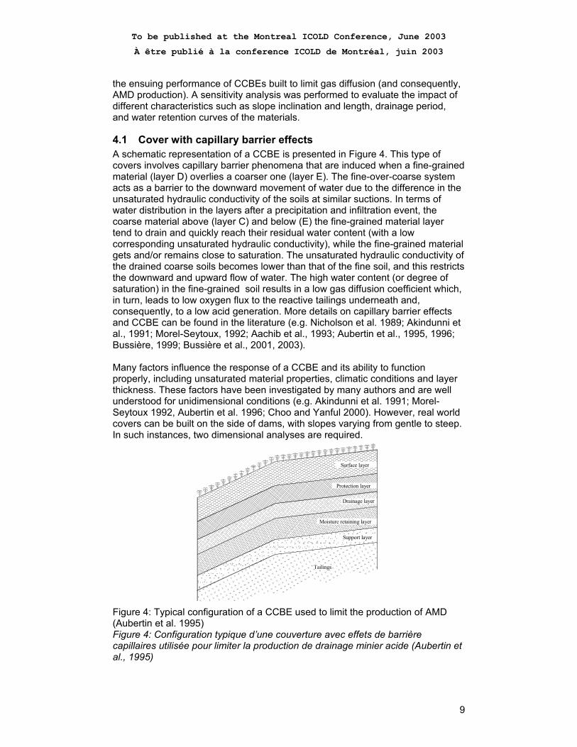
4.1 Cover with capillary barrier effects A schematic representation of a CCBE is presented in Figure 4. This type of covers involves capillary barrier phenomena that are induced when a fine-grained material (layer D) overlies a coarser one (layer E). The fine-over-coarse system acts as a barrier to the downward movement of water due to the difference in the unsaturated hydraulic conductivity of the soils at similar suctions. In terms of water distribution in the layers after a precipitation and infiltration event, the coarse material above (layer C) and below (E) the fine-grained material layer tend to drain and quickly reach their residual water content (with a low corresponding unsaturated hydraulic conductivity), while the fine-grained material gets and/or remains close to saturation. The unsaturated hydraulic conductivity of the drained coarse soils becomes lower than that of the fine soil, and this restricts the downward and upward flow of water. The high water content (or degree of saturation) in the fine-grained soil results in a low gas diffusion coefficient which, in turn, leads to low oxygen flux to the reactive tailings underneath and, consequently, to a low acid generation. More details on capillary barrier effects and CCBE can be found in the literature (e.g. Nicholson et al. 1989; Akindunni et al., 1991; Morel-Seytoux, 1992; Aachib et al., 1993; Aubertin et al., 1995, 1996; Bussière, 1999; Bussière et al., 2001, 2003). Many factors influence the response of a CCBE and its ability to function properly, including unsaturated material properties, climatic conditions and layer thickness. These factors have been investigated by many authors and are well understood for unidimensional conditions (e.g. Akindunni et al. 1991; Morel-Seytoux 1992, Aubertin et al. 1996; Choo and Yanful 2000). However, real world covers can be built on the side of dams, with slopes varying from gentle to steep. In such instances, two dimensional analyses are required.
Surface layer
Protection layer
Drainage layer
Moisture retaining layer
Support layer
Tailings
Figure 4: Typical configuration of a CCBE used to limit the production of AMD (Aubertin et al. 1995) Figure 4: Configuration typique d’une couverture avec effets de barrière capillaires utilisée pour limiter la production de drainage minier acide (Aubertin et al., 1995)
To be published at the Montreal ICOLD Conference, June 2003
À être publié à la conference ICOLD de Montréal, juin 2003
10
4.2 Geometry and hydraulic parameters When a CCBE is inclined, the effects of both vertical and horizontal unsaturated flow must be considered (e.g. Aubertin et al., 1997; Bussière, 1999; Bussière et al., 2003). Due to the particular geometry (inclined layered system), the different material properties, and the variable boundary conditions, the hydraulic behaviour of a given CCBE can be predicted only by the use of unsaturated water flow numerical modeling. The numerical model used in this study is based on a real situation. The main characteristics of the model and materials are: • The length of the sloping cover, depending on the case simulated, is either 50
m or 100 m and the inclination α varies between 11.3° and 18.4° (5H:1V to 3H:1V).
• The model also includes a 25 m horizontal section on top of the dump. Preliminary numerical analyses have indicated that, at this location, the horizontal flow in the cover becomes negligible so a no flux boundary condition was applied to limit the size of the model (see Figure 5).
• The phreatic surface in the sulphide tailings was initially located where it had been observed from piezometer readings in the field (based on an actual case study at the LTA site ; see McMullen et al., 1997, for more details).
• In the simulations, the existing toe drain at the base of the slope was introduced.
• Evaporation was not directly considered for the calculations as previous studies have shown that it should not have a significant effect on the behaviour of the moisture-retaining layer in a three-layer system such as the cover simulated in this study (Yanful and Choo, 1997; Aachib, 1997; Aubertin et al., 1999).
• The initial pressure head at each node, required for transient analyses, was obtained from steady state analysis using the same model. In that simulation, an infiltration flux of 30 mm/month (average site conditions for precipitation minus evaporation) was applied to the top of the cover. Starting from these initial conditions, a drainage period of 60 days was then simulated for each scenario; this period corresponds to an extreme drought situation for a humid climate.
• The thickness of the different layers of the CCBE are: 0.5 m of sand at the bottom, 0.8 m of fine-grained material (three types of material were studied: MRN-Tailings, Fine Silt and Coarse Silt), and 0.3 m of sand at the top.
• The hydraulic functions, required for each material to perform numerical modelling of unsaturated flow in porous media are presented in Figures 6 and 7. As can be observed in Figure 6, there is a significant difference in the water retention properties between the LTA-Sand and the fine-grained materials (MRN-Tailings, Fine Silt and Coarse Silt) used for the water retention layer. This contrast is very useful for creating an effective cover with capillary barrier effects.
• Permeability functions, presented in Figure 15, were determined from the corresponding WRC with the closed form analytical expression (see Equations 2 and 3) of the Mualem (1976) model proposed by van Genuchten (1980).
More details on these numerical simulations can be found in Bussière (1999) and Bussière et al. (2003).

To be published at the Montreal ICOLD Conference, June 2003
À être publié à la conference ICOLD de Montréal, juin 2003
11
25 50 75 100-202468
10121416
Figure 5: Typical mesh used in the unsaturated flow calculations Figure 5: Maillage typique utilisé lors des modélisations numériques de l’écoulement de l’eau en milieu non saturé
0
0.05
0.1
0.15
0.2
0.25
0.3
0.35
0.4
0.45
0.5
1 10 100 1000 10000Suction (cm of water)
Volu
met
ric w
ater
con
tent
LTA-SandMRN-TailingsSulphidic tailingsFine SiltFondation SiltCoarse Silt
Figure 6: Water retention curves of the materials used in the numerical study Figure 6: Courbes de rétention d’eau des matériaux utilisés dans les modélisations numériques
1.00E-11
1.00E-10
1.00E-09
1.00E-08
1.00E-07
1.00E-06
1.00E-05
1.00E-04
1.00E-03
1.00E-02
1.00E-01
1.00E+00
1 10 100 1000 10000Suction (cm of water)
Hyd
raul
ic c
ondu
ctiv
ity (c
m/s
)
LTA-SandMRN-TailingsSulphidic TailingsFine SiltFondation SiltCoarse Silt
Figure 7: Permeability functions of the materials used in the numerical study Figure 7: Fonctions de perméabilité des matériaux utilisés dans les modélisations numériques

To be published at the Montreal ICOLD Conference, June 2003
À être publié à la conference ICOLD de Montréal, juin 2003
12
4.3 Results To evaluate the influence of material properties, slope inclination and length, and drainage time on the hydraulic behaviour of a CCBE, ten simulations were performed. The main characteristics of each simulation are presented in Table 4. Because of space constraints, only a few sample results are presented in Figures 8 to 11. Table 4: Main characteristics of the numerical simulations performed on covered tailings dams. Tableau 4: Principales caractéristiques des simulations numériques sur les digues de rejets miniers recouvertes d’une CEBC Simulation Slope
Inclination Slope
length (m) Moisture-retaining
material (m of water)
Boundary conditions
#1 3:1 50 MRN-Tailings drainage 60 days #2 3:1 50 Fine Silt drainage 60 days #3 4:1 50 MRN-Tailings drainage 60 days #4 5:1 50 MRN-Tailings drainage 60 days #5 3:1 100 MRN-Tailings drainage 60 days #6 4:1 100 MRN-Tailings drainage 60 days #7 5:1 100 MRN-Tailings drainage 60 days #8 3:1 100 Fine Silt drainage 60 days #9 3:1 100 Coarse Silt drainage 60 days #10 3:1 50 Coarse Silt drainage 60 days The main observations from the numerical results can be summarised as follows: • For a similar drainage period (60 days in Figure 8 and 9), one can observe
that the slope influences the moisture distribution in the water-retaining layer. The steepest slope typically induces lower water content at a given distance from the bottom than one that is less inclined.
• If the distance between the phreatic surface and the cover remains the same, the length of the slope does not significantly affect the moisture-distribution in the moisture-retaining layer (see Figures 8 and 11).
• By comparing Figures 8 and 10, one can see that the water-retention properties of the material used in the moisture-retaining layer significantly affect the moisture distribution in the CCBE. For example, the lowest volumetric water content observed, after 60 days of drainage, in Figure 10 was 0.41 (Fine Silt as moisture-retaining material) compared to 0.35 in Figure 8 (MRN-Tailings as moisture-retaining material).

To be published at the Montreal ICOLD Conference, June 2003
À être publié à la conference ICOLD de Montréal, juin 2003
13
0.35
0.35
0.37
0.39
0 .4 1
45 55 65 75 85 95 105 115-2-101234567891011121314151617
Figure 8: Volumetric water content distribution after 60 days of drainage for the following characteristics: 3:1 slope inclination, MRN-Tailings as moisture-retaining material, and a 50m long slope Figure 8: Distribution de la teneur en eau volumique après 60 jours de drainage pour les caractéristiques suivantes du modèle: inclinaison de 3:1, couche de rétention d’eau constituée du MRN-Tailings et longueur de pente de 50 m
0.35
0.37
0.39
0.41
45 55 65 75 85 95 105 115-2-1012345678910111213
Figure 9. Volumetric water content distribution after 60 days of drainage for the following model characteristics: 5:1 slope inclination, MRN-Tailings as moisture-retaining material, and a 50m long slope Figure 9: Distribution de la teneur en eau volumique après 60 jours de drainage pour les caractéristiques suivantes du modèle: inclinaison de 5:1, couche de rétention d’eau constituée du MRN-Tailings et longueur de pente de 50 m

To be published at the Montreal ICOLD Conference, June 2003
À être publié à la conference ICOLD de Montréal, juin 2003
14
0.41
0.43
45 55 65 75 85 95 105 115-2-101234567891011121314151617
Figure 10. Volumetric water content distribution after 60 days of drainage for the following model characteristics: 3:1 slope inclination, Fine Silt as moisture-retaining material, and a 50m long slope Figure 10: Distribution de la teneur en eau volumique après 60 jours de drainage pour les caractéristiques suivantes du modèle: inclinaison de 3:1, couche de rétention d’eau constituée du Fine Silt et longueur de pente de 50 m
0.35
0.35
0.37
0.39
0.41
45 55 65 75 85 95 105 115 125 135 145 155 165-2-101234567891011121314151617181920212223242526272829303132
Figure 11. Volumetric water content distribution after 60 days of drainage for the following model characteristics: 3:1 slope inclination, MRN-Tailings as moisture-retaining material, and a 100m long slope. Figure 11: Distribution de la teneur en eau volumique après 60 jours de drainage pour les caractéristiques suivantes du modèle: inclinaison de 3:1, couche de rétention d’eau constituée du MRN-Tailings et longueur de pente de 100 m

To be published at the Montreal ICOLD Conference, June 2003
À être publié à la conference ICOLD de Montréal, juin 2003
15
4.4 Influence of the geometry on the performance of the CCBE To relate the effect of the geometry to the performance of a CCBE used to limit gas migration by diffusion, a new indicative parameter was proposed by the authors based on the numerical results: the average effective diffusion coefficient for the sloping cover (De_Slope). Parameter De_Slope is evaluated here, in a simplified manner, by determining the value of the degree of saturation Sr (θ/n with n=θsat=0.44; see Figure 6) for each node at mid-depth in the moisture-retaining layer. From these Sr values, it is possible to estimate the equivalent effective diffusion coefficient using predictive equations (e.g. Millington and Shearer, 1971; Collin and Rasmuson, 1988; Aachib et al., 2002). The De_Slope parameter is used here for indicative purposes to allow comparison of different configurations and material properties (but not for actual oxygen flux calculations). Parameter De_slope was calculated for the ten simulations to evaluate the relative performance of the CCBE. It is then possible to use such numerical results to quantify, in a relative manner, the effects of these factors on the performance of an inclined CCBE. To represent the capillary barrier effects in the cover, the term (ψaF-ψrC) is used, where ψaF is the air entry value of the fine-grained material and ψrC is the residual suction for the bottom coarse-grained material (both expressed in m of water). This term, initially proposed by Nicholson et al. (1989) to evaluate the moisture-retaining layer thickness of horizontal CCBE, can also be used to represent the capacity of such layers to remain close to saturation; a larger (ψaF-ψrC) value usually induces better CCBE performance. The performance indicator of the cover (expressed by the parameter De_Slope) is normalised by the inclination of the slope (α). A relationship between cover materials properties (ψaF-ψrC), slope inclination (α), drainage time tD and the relative performance of the sloping CCBE to limit gas migration (De_Slope) can be expressed mathematically as follow (Bussière et al. 2003):
( )[ ]( ) αψψ tanexp 321_ aaaD aFrCSlopee −−+= (6)
where a1 and a3 take fixed values of 5.2x10⁻¹¹ and 15 respectively, and a2 can be estimated with the following linear relationship:
4.00481.02 −= Dta (7)
where tD is the drainage time expressed in days (for instance, if tD = 60 days, a2.= 2.5). It is important to note that boundary conditions have been integrated into these equations. The best performance of a CCBE is associated to a De_Slope value between 10-9 and 10-10 m2/s, for slope angles between 1 and 20°. Such lower boundary values correspond to the effective diffusion coefficient of highly saturated soils (Elberling et al. 1994; Mbonimpa et al., 2002) and are reached asymptotically for a (De_Slope/tanα) value of 5.2x10⁻¹¹. However, when the hydraulic contrast between the fine- and coarse-grained materials is reduced (low values of ψaF-ψrC), the De_Slope value corresponds to a soil layer with a relatively low degree of saturation (De between 5x10⁻⁵ and 2.5x10⁻⁷ m²/s). The proposed empirical equations (Equations 6 and 7) are considered valid for the following specific conditions:

To be published at the Montreal ICOLD Conference, June 2003
À être publié à la conference ICOLD de Montréal, juin 2003
16
• The elevation and length of the sloping cover is sufficient to induce a significant slope effect (i.e. elevation variation between the top and the bottom of the slope should be greater than ψaF).
• The phreatic surface should be relatively near the surface (depth of less than about 3 m), similar to that observed with tailings ponds located in humid climates.
• The climatic and other degradation factors (like wetting-drying and freeze-thaw cycles, animal and roots intrusions) do not change the hydraulic properties (such as WRC) of the materials.
5. Summary and conclusion
Unsaturated flow modelling is a powerful tool that can be used to assist engineers in the design of infrastructures like dams and covers. In this paper, the authors used a FE calculation results to develop simple equations that allow the integration of the unsaturated flow component into the preliminary calculations for the design of tailings impoundment dams and CCBE’s. The advantage of these equations is that they provide rapid estimates that may be very useful during preliminary stages of a project. In the first part of the paper, numerical modelling was used to study conditions of saturated and unsaturated seepage through homogeneous dams and central core dams. When the unsaturated seepage is taken into account, it was found that: • The steady-state seepage flowrate is higher (usually between 10 and 20%,
and even more for smaller dams) than that calculated with approximate methods (hand drawing or electrical analogy) that neglect the unsaturated flow component (see Chapuis and Aubertin, 2001, for details).
• A single equation, based on numerical results, can be used to estimate the seepage rate of a dam as a function of dam geometry and saturated hydraulic conductivity of its impervious material.
• The numerical results illustrate that the complete solution of a saturated and unsaturated flow problem provides better information relative to positive and negative pore water pressures. This also permits a better evaluation of any mechanical problem (deformation analysis, stability analysis).
The second part of the paper deals with the transient unsaturated flow through covers with capillary barrier effects (CCBE) built on dams. In this case, the geometry of the dam affects the ability of the CCBE to limit oxygen migration and, consequently, AMD production from the sulphide tailings underneath. The numerical study show that: • The slope significantly affects the value of parameter De_slope during a
drainage period. Because of this, it also affects the performance of a cover to limit gas diffusion. The results indicate that the inclination effect on parameter De_slope is amplified with increased drainage time.
• The length of the slope may also affect the water distribution in the CCBE, as shown in Figure 11. However, the value of parameter De_slope calculated from these profiles indicates that the length would not significantly affect its magnitude for the cover, for these relatively steep angles.

To be published at the Montreal ICOLD Conference, June 2003
À être publié à la conference ICOLD de Montréal, juin 2003
17
• The contrast between the fine- and coarse-grained soils is a critical parameter on the hydraulic behaviour of inclined CCBE, and on its ensuing ability to limit oxygen flux.
The authors propose a simple equation (based on water retention properties of soils, drainage time, and geometry of the CCBE), which can be used as a preliminary tool for quantifying the relative performance of sloping covers with capillary barrier effects. For actual field applications of a CCBE used to limit gas diffusion, the authors recommend evaluation of the potential for desaturation with Equations 6 and 7, and a subsequent use of transient 2D (or even 3D) calculations if the risk of desaturation is deemed to exist. If desaturation at the top of an inclined CCBE is a source of concern, other studies would be necessary, including detailed calculation of oxygen fluxes along the slope to evaluate the effect of the controlling parameters on AMD production.
6. Acknowledgement
The authors would like to thank NSERC and the participants to the industrial NSERC Polytechnique-UQAT Chair on Environment and Mine Wastes Management for their financial support.
7. References
Aachib, M, Aubertin, M, and Mbonimpa, M. 2002. Laboratory measurements and predictive equations for gas diffusion coefficient of unsaturated soils. Proceedings of the 55th Canadian Geotechnical and 3rd Joint IAH-CNC and CGS Groundwater Speciality Conferences, Niagara Falls, October 2002, pp. 163-171.
Aachib, M. 1997. Étude en laboratoire de la performance des barrières de recouvrement constituées de rejets miniers pour limiter le DMA. Ph.D. Thesis, Mineral Engineering Department, École Polytechnique de Montréal.
Aachib, M., Aubertin, M. and Chapuis, R.P. 1993. Étude en laboratoire de la performance des barrières de recouvrement constituées de rejets miniers pour limiter le drainage minier acide - Un état de la question. Report EPM/RT-93/32, École Polytechnique de Montréal.
Akindunni, F.F., Gillham, R.W. and Nicholson, R.V. 1991. Numerical simulations to investigate moisture-retention characteristics in the design of oxygen-limiting covers for reactive mine tailings. Canadian Geotechnical Journal, 28 :446-451.
Aubertin, M., Mbonimpa, M., Bussière, B. and Chapuis, R.P. 2003. A physically based model to predict the water retention curve from basic geotechnical properties. Canadian Geotechnical Journal (to be published)).
Aubertin, M., Bussière, B. and Bernier, L. 2002. Environnement et gestion des résidus miniers. Manual on CD, Les Éditions de l'École Polytechnique de Montréal.
Aubertin, M., Bussière, B., Joanes, A.-M., Monzon, M. Gagnon, D., Barbera, J.-M., Bédard, C., Chapuis, R.P. and Bernier, L. 1999. Projet sur les barrières sèches construites à partir de résidus miniers, Phase II: essais en place. MEND Report 2.22.2c.

To be published at the Montreal ICOLD Conference, June 2003
À être publié à la conference ICOLD de Montréal, juin 2003
18
Aubertin, M., Ricard, J.F. and Chapuis, R.P. 1998. A predictive model for the water retention curve : application to tailings from hard rock mines. Canadian Geotechnical Journal, 35:55-69.
Aubertin, M., Chapuis, R.P., Bouchentouf, A. and Bussière, B. 1997. Unsaturated flow modeling of inclined layers for the analysis of covers. Proceedings of the 4thICARD, Vancouver, B.C., 2 : 731-746.
Aubertin, M., Bussière, B., Aachib, M., Chapuis, R.P., and Crespo, R. 1996. Une modélisation numérique des écoulements non saturés dans les couvertures multicouches en sols. Hydrogéologie, 96(1): 3-13.
Aubertin, M., Chapuis, R.P., Aachib, M., Bussière, B., Ricard, J.-F. and Tremblay, L. 1995. Évaluation en laboratoire de barrières sèches construites à partir de résidus miniers. MEND Report 2.22.2a.
Averjanov, S.F. 1950. About permeability of subsurface soils in case of incomplete saturation. English Collection, 7: 19-21.
Barbour, S.L. and Yanful, E.K. 1994. A column study of static nonequilibrium fluid pressures in sand during prolonged drainage. Canadian Geotechnical Journal, 31 :299-303.
Bathe, K-J. 1982. Finite Element Procedures in Engineering Analysis. Prentice-Hall.
Bear, J. 1972. Dynamics of Fluids in Porous Media. Dover Publications Inc., New York.
Burdine, N.T. 1953. Relative permeability calculations from pore-size distribution data. Trans. Am. Inst. Of Min. and Metallurgical and Pet. Engrs., 198: 71-78
Bussière, B., Aubertin, M. and Chapuis, R.P. 2003. The behavior of inclined covers used as oxygen barriers. Canadian Geotechnical Journal (to be published).
Bussière, B., Aubertin, M. and Julien, M. 2001. Couvertures avec effets de barrière capillaire pour limiter le drainage minier acide: aspects théoriques et pratiques. Vecteur environnement, 34(3): 37-50.
Bussière, B., Idrissi, M., Elkadri, N. and Aubertin, M. 2000. Simulation des écoulements dans les milieux poreux de saturation variable à l'aide de la formulation mixte de l'équation de Richards. 1st Joint IAH-CNC-CGS Groundwater Specialty Conference, Montréal, 335-342.
Bussière, B. 1999. Étude du comportement hydrique de couvertures avec effets de barrière capillaire inclinées à l'aide de modélisations physiques et numériques. Ph.D. Thesis, Mineral Engineering Department, École Polytechnique de Montréal, 354 pages.
Bussière, B., Aubertin, M., Aachib, M., Chapuis, R.P. and Crespo, R.J. 1995. Unsaturated Flow Modelling of Covers for Reactive Tailings. CAMI ’95, 3rd Canadian Conference on Computer Applications in the Mineral Industry, Montréal, 853-862.
Chapuis, R.P. and Aubertin, M. 2001. A simplified method to estimate saturated and unsaturated seepage through dikes under steady state conditions. Canadian Geotechnical Journal, 38: 1321-1328.
Chapuis, R.P., Chenaf, D., Bussière, B., Aubertin, M. and Crespo, R. 2001. A user's assessment of numerical codes for saturated and unsaturated seepage conditions. Canadian Geotechnical Journal, 38: 1113-1126.
Chapuis, R.P., Crespo, R., Chenaf, D. and Aubertin, M. 1993. Evaluation of a ground water F.E.M. software for steady and unsteady state conditions. Proceedings, 46th Canadian Geotechnical Conference, Saskatoon, pp.61-70.
Childs, E.C. and Collis-George, G.N. 1950. The permeability of porous materials. Proceedings of the Royal Society of London, Series A, 201 : 392-405.
To be published at the Montreal ICOLD Conference, June 2003
À être publié à la conference ICOLD de Montréal, juin 2003
19
Choo, L-P. and Yanful, E.K. 2000. Water flow through cover using modeling and experimental methods. Journal of Geotechnical and Geoenvironmental Engineering, 126 : 324-334.
Clement, T.P., Wise, W.R. and Molz, F.J. 1994. A physically based, two-dimensional, finite difference algorithm for modeling variably saturated flow. Journal of Hydrology, 161 : 71-90.
Collin, M. and Rasmuson, A. 1988. A comparison of gas diffusivity models for unsaturated media. Soil Sci. Soc. Am. J., 52 :1559-1565.
Elberling, B., Nicholson, R. V., Reardon, E. J., and Tibble, P. 1994. Evaluation of sulphide oxidation rates: a laboratory study comparing oxygen fluxes and rates of oxidation product release. Canadian Geotechnical Journal, 31: 375-383.
Farthing, M.W., Kees, C.E. and Miller, C.T. (2003). Mixed finite element methods and higher order temporal approximations for variably saturated groundwater flow. Advances in Water Resources, 26 : 373-394.
Fedors, R.W. 1996. Improvement in nonlinear solution schemes for saturated-unsaturated flow regimes. Proceedings of the 16th Annual American Geophysical Union Hydrology Days, H.J. Morel-Seytoux (ed.), Fort Collins, Colorado, 467-478.
Fredlund, D.G., Xing, A. and Huang, S. 1994. Predicting the permeability function for unsaturated soils using the soil-water characteristic curve. Canadian Geotechnical Journal, 31: 533-546.
Fredlund, D.G. and Rahardjo, H. 1993. Soil Mechanics for Unsaturated Soils. John Wiley & Sons, inc., New York.
Gardner, W.R. 1958. Some steady state solutions of unsaturated moisture flow equations with application to evaporation from a water table. Soil Science, 85 : 228-232.
GEOSLOPE International 1998. SEEP/W User's Guide. Green, R.E. and Corey, J.C. 1971. Calculation of hydraulic conductivity: a further
evaluation of some predictive models. Soil Science Society of America Proceedings, 35:3-8.
Healy, R.W. 1990. Simulation of solute transport in variably saturated porous media with supplemental information on modification to the US Geological Survey’s computer program VS2D. US Geol. Surv. Water-Resour. Invest. Rep., 90-4025.
Hillel, D. 1980. Fundamental of Soil Physics. Academic Press, New York. Holder, A.W., Bedient, P.B. and Dawson, C.N. (2000). FLOTRAN, a three-
dimensional ground water model, with comparison to analytical solutions and other models. Advances in Water Resources, 23 : 517-530.
Huyakorn, P.S., Springer, E.P., Guvanasen, V. and Wadsworth, T.D. 1986. A three dimensionnal finite-element model for simulating water flow in variably saturated porous media. Water Resources Research, 22 : 1790-1808.
Huyakorn, P.S., Thomas, S.D. and Thompson, B.M. 1984. Techniques for making finite elements competitive in modeling flow in variably saturated media. Water Resources Research, 20 : 1099-1115.
Klute, A. and Dirksen, C. 1986. Hydraulic conductivity and diffusivity : laboratory methods. Methods of Soil Analysis, Part I, 2nd Edition, A. Klute (ed.), Agron. Monogr. No. 9, ASA and SSSA, Madison, WI, 687-734.
Leij, F.J., Russell, W.B. and Lesch, S.M. 1997. Closed-form expressions for water retention and conductivity data. Ground Water, 35: 848-858.

To be published at the Montreal ICOLD Conference, June 2003
À être publié à la conference ICOLD de Montréal, juin 2003
20
Leong, E.C. and Rahardjo, H. 1997. Review of soil-water characteristic curve equations. Journal of Geotechnical et Geoenvironmental Engineering, 123: 1106-1117.
Mbonimpa, M., Aubertin, M., Aachib, M. and Bussière, B. 2002. Oxygen diffusion and consumption in unsaturated cover material. Technical Report EPM-RT-02-04, École Polytechnique de Montréal.
McMullen, J., Firlotte, R., Knapp, R. and Aubertin, M. 1997. Les Terrains Aurifères property site closure and rehabilitation - conceptual to construction. Proceedings of the 29th Annual Meeting of the Canadian Mineral Processors, Ottawa, 274-292.
MEND 2001. MEND Manual, Report 5.4.2, Volume 4 – Prevention and Control, Secretariat CANMET.
Millington, R. J. and Shearer, R. C. 1971. Diffusion in aggregated porous media. Soil Science, 57: 1200-1207.
Morel-Seytoux, H.J.1992. The capillary barrier effect at the interface of two soil layers with some contrast in properties. HYDROWAR Report 92.4, Hydrology Days Publications, 57 Shelby Lane, Atherton, CA 94027-3926.
Mualem, Y. 1986. Hydraulic conductivity of unsaturated soils : Prediction and formulas. Methods of Soil Analysis, Part I, 2nd Edition, A. Klute (ed.), Agron. Monogr. No. 9, ASA and SSSA, Madison, WI, 799-823.
Mualem, Y. 1976. A new model for predicting the hydraulic conductivity of unsaturated porous media. Water Resources Research, 12 : 513-522.
Neumann, S.P. 1973. Saturated-unsaturated seepage by finite elements. J. Hydraulic. Div. ASCE, 99 (HY12) : 2233-2250.
Nicholson, R. V., Gillham, R. W., Cherry, J. A., and Reardon, E. J. 1989. Reduction of acid generation in mine tailings through the use of moisture-retaining cover layers as oxygen barriers. Canadian Geotechnical Journal, 26: 1-8.
Richards, L.A. 1931. Capillary conduction of liquids through porous medium. J. Physics. 1 : 318-333.
Rijtema, P.E. 1965. An analysis of actual evapotranspiration. Rep. 659, Cent. For Agri. Publ. and Doc., Wageningen, Netherlands.
van Genuchten, M.Th. 1980. A closed-form equation for predicting the hydraulic conductivity of unsaturated soils. Soil Science Society of America Journal, 44: 892-898.
Woyshner, M.R. and Yanful, E.K. 1995. Modelling and field measurements of water percolation through an experimental soil cover on mine tailings. Canadian Geotechnical Journal, 32 : 601-609.
Yanful, E.K. and Choo, L-P. 1997. Measurement of evaporative fluxes from candidate cover soils. Canadian Geotechnical Journal, 34 : 447-459.
Yeh, T.-C. J., Guzman, A., Srivastava, R. and Gagnard, P.E. 1994. Numerical simulation of the wicking effect in liner systems. Ground Water, 32 : 2-11.
Yuster, S.T. 1951. Theoritical, consideration of multiphase flow in idealized capillary systems. Proceedings of 3rd World Pet. Congr., 2:437-445.