university*of*florida* dept.*of*electrical*and*computer ... reports... ·...
TRANSCRIPT

University of Florida Dept. of Electrical and Computer Engineering EEL 4665/5666 Intelligent Machines Design Laboratory
Atheris Formal Report
Devron Lee Instructors: Dr. A. Antonio Arroyo Dr. Eric M. Schwartz TAs: Mike Pridgen Thomas Vermeer Tim Martin Devin Hughes Ryan Stevens

D Lee | 1
CONTENTS Abstract ..........................................................................................................................................................................................2
Introduction .................................................................................................................................................................................3 Background..............................................................................................................................................................................3
Scope and Objectives ...........................................................................................................................................................3 Integrated System......................................................................................................................................................................4
System Block Diagram ........................................................................................................................................................4
Atheris Control Board .........................................................................................................................................................4 Control / Motor Power .......................................................................................................................................................5
Electronic Speed Controller and Motor .......................................................................................................................6
IR Sensors .................................................................................................................................................................................6 Hall Effect Sensor ..................................................................................................................................................................6
3-‐Axis Accelerometer ..........................................................................................................................................................7 Servos .........................................................................................................................................................................................7
XBee Module............................................................................................................................................................................7
Payload Bay..............................................................................................................................................................................7 Mobile Platform ..........................................................................................................................................................................8
Actuation........................................................................................................................................................................................9
Scope and Objectives ...........................................................................................................................................................9 Types, Purpose, and Application of Actuation..........................................................................................................9
Brushless DC Motor.........................................................................................................................................................9 Servo ...................................................................................................................................................................................11
Behaviors ....................................................................................................................................................................................13
Scope and Objectives ........................................................................................................................................................13 Conclusion..................................................................................................................................................................................14
Appendix .....................................................................................................................................................................................15

D Lee | 2
ABSTRACT Atheris is an autonomous ground vehicle capable of meeting dynamic mission requirements. It features high speed, intelligent movement, a rugged skeleton, and one modular payload bay. It utilizes IR sensors and a 3-‐axis accelerometer for obstacle avoidance and collision detection.

D Lee | 3
INTRODUCTION
BACKGROUND Unmanned vehicles are becoming an increasingly attractive solution to minimizing costs and risks to humans when performing routine or dangerous tasks. Autonomous unmanned ground vehicles see use in a variety of applications, from combat to automated navigation. Some of these vehicles are versatile, with articulated appendages and specialized sensor packages, while others are agile. All of the vehicles, however, have tradeoffs between versatility, speed, and size.
SCOPE AND OBJECTIVES The primary goal of this project was the construction of a smart, adaptable, autonomous platform that can execute dynamic mission objectives. It required a rugged skeleton and shell for structural integrity, and had the ability to travel at speed in order to cover terrain or evade capture.
The Atheris platform attempted to meet the versatility requirement with a varied default sensor array and one modular payload bay. The Atheris could be retrofitted with a payload specific to its mission objective immediately prior to deployment. Additional versatility will be achieved by enabling the platform to act in a swarm configuration. While the available time and funding may be insufficient for building a second robot to demonstrate swarm functionality, the capability can be included in at least a basic level. For example, by leveraging XBEE modules, which automatically set up a mesh network, the single robot becomes a node in a mesh containing just itself, and additional computers could simulate the presence of additional robots by communicating with the mesh through their own XBEE modules.
The speed objective was accomplished by using a brushless motor system and a gear ratio tuned such that the robot could accelerate and travel rapidly. Long range, high speed sensors should be utilized so that the robot can avoid obstacles while maintaining its speed. Torque requirements on the motor were reduced by using composite materials, specifically carbon fiber, for as much of the skeleton and skin as will be appropriate. Using composite materials reduced the body weight and put less strain on the motor.
The Atheris robot was roughly the size of a 1/10 scale remote control truck, thereby achieving a small form factor.

D Lee | 4
INTEGRATED SYSTEM
SYSTEM BLOCK DIAGRAM The components comprising the Atheris are shown in figure 1.
Figure 1. Block Diagram of Integrated System
ATHERIS CONTROL BOARD The Atheris control board is the driving intelligence of the robot. The board has dedicated PWM channels, ADC, input capture, and multifunction GPIO ports so that it can interface to the rest of the system.

D Lee | 5
Figure 2. Detail of Atheris control board
Features: AVR32 -‐ AT32UC3B1256 ADC -‐ AD7908 3-‐Axis Accelerometer – ADXL345
CONTROL / MOTOR POWER The power to the control system and motor was provided through two-‐cell Li-‐Poly batteries that were monitored and conditioned via a dedicated power management board.
Figure 3. Detail of power management board

D Lee | 6
Features: 2.25A Regulator – PTH08080W Solid-‐state Relay Controllable Power Indicator LED Battery voltage outputs for monitoring ESC Feed-‐through
ELECTRONIC SPEED CONTROLLER AND MOTOR The electronic speed controller and motor are off the shelf components that are controlled by the Atheris control board. The electronic speed controller handles all of the power management for the motor.
IR SENSORS Four IR sensors (2x Sharp GP2Y0A02YK0F and 2x Sharp GP2D120) were used to provide mid to short range obstacle detection.
Figure 4. Detail of IR sensors
Although the datasheet described the sensors as having a maximum range of 150cm, the sensors actually were useful for roughly half of that range. Additionally, the sensors were virtually useless in daylight or for detecting black surfaces due to heavy interference from the former and almost complete absorption in the latter. Some characteristic that proved critical for the robot were the low speed and noisiness of the sensors – the robot moved fast enough that it would collide with an obstacle while it was being detected or before the sensors could “see” it.
HALL EFFECT SENSOR
D Lee | 7
A Hall effect sensor, coupled with magnets embedded in the rear wheel, provided a means of calculating the velocity of the robot. It was connected to the input capture peripheral, which in turn was clocked from a real time clock, so as to provide an accurate measurement of the time take for a revolution of the rear wheel. Only two magnets were used, and they were placed on opposite ends of a diameter of the rear tire and in opposite polar configurations so that they would set and unset the Hall effect sensor over the course of one revolution.
3-‐AXIS ACCELEROMETER An ADXL345 digital 3-‐axis accelerometer was used for collision detection in the robot. It features tap and double tap detection, which were used to detected acceleration impulses arising from collision events. The tap and double tap detection were also used as option means of arming and starting the robot.
SERVOS High torque, digital servo (TRA2070) was used for steering.
XBEE MODULE A wireless XBee module provided a means of meshed networking, untethered debugging, and a master override.
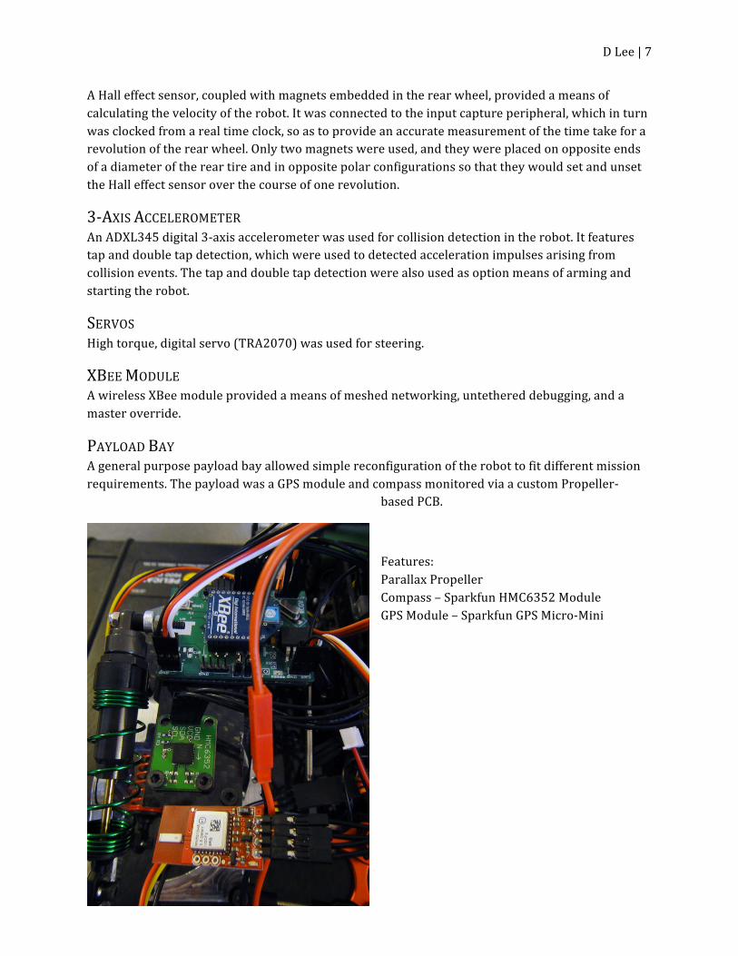
PAYLOAD BAY A general purpose payload bay allowed simple reconfiguration of the robot to fit different mission requirements. The payload was a GPS module and compass monitored via a custom Propeller-‐
based PCB.
Features: Parallax Propeller Compass – Sparkfun HMC6352 Module GPS Module – Sparkfun GPS Micro-‐Mini
Figure 5. Detail of payload

D Lee | 8
MOBILE PLATFORM The Atheris mechanical framework is constructed mostly from milled aluminum (6061 T6). The material was chosen because of its light weight, low cost, and relatively high strength. The particular alloy was chosen for its favorable machining and strength characteristics.
Locomotion is provided via the rear wheel, which is powered from a belt drive configuration.
Figure 6. Render Generated from early Solidworks Model

D Lee | 9
ACTUATION
SCOPE AND OBJECTIVES All of the primary actuation on the Atheris will be rotational actuation for both primary locomotion and steering.
TYPES, PURPOSE, AND APPLICATION OF ACTUATION
BRUSHLESS DC MOTOR Castle Creations Mamba Max Pro ESC Castle Creations CMS36-‐5700 A brushless DC motor provided rotational actuation, and applied this actuation to a system of gears and a belt drive to power the rear wheel. The purpose of the motor was to provide high rotation speed and torque to allow the robot to meet its speed and acceleration objectives. To meet the speed objective, a 100000RPM brushless motor was selected and controlled by an electronic speed controller capable of supplying more than 100A continuous current to the motor. The electronic speed controller was programmed via a 50Hz PWM signal. The characteristics of the PWM are nearly identical to a PWM signal used for controlling a servo: the neutral position is at a 1.5ms pulse width, and 1ms to 2ms pulse widths correspond to full reverse throttle and full forward throttle, respectively.

D Lee | 10
Figure 7. Detail of the motor and speed controller
The final drive ratio was 16.5:1, which include a 12 tooth pinion gear, 90 tooth spur gear, 20 tooth drive pulley, and a 90 tooth tail pulley. This gearing ratio was matched to the roll-‐out length of the rear tire (132mm outer diameter).

D Lee | 11
Figure 8. Detail of motor gearing
With the two cell Li-‐Poly battery selected for the motor battery, the estimated speed of the robot was 44.4mph. Unfortunately, this estimation was never verified. The robot remained almost entirely between 5% and 10% of full throttle because of sensor limitations.
Figure 9. Detail of belt drive
SERVO TRA2070 A high-‐torque digital servo provided rotational actuation to a steering link. The steering link
D Lee | 12
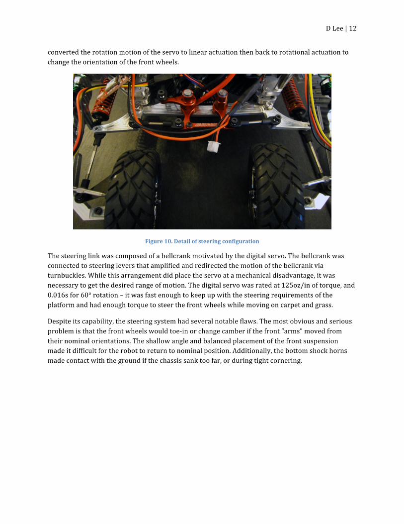
converted the rotation motion of the servo to linear actuation then back to rotational actuation to change the orientation of the front wheels.
Figure 10. Detail of steering configuration
The steering link was composed of a bellcrank motivated by the digital servo. The bellcrank was connected to steering levers that amplified and redirected the motion of the bellcrank via turnbuckles. While this arrangement did place the servo at a mechanical disadvantage, it was necessary to get the desired range of motion. The digital servo was rated at 125oz/in of torque, and 0.016s for 60° rotation – it was fast enough to keep up with the steering requirements of the platform and had enough torque to steer the front wheels while moving on carpet and grass.
Despite its capability, the steering system had several notable flaws. The most obvious and serious problem is that the front wheels would toe-‐in or change camber if the front “arms” moved from their nominal orientations. The shallow angle and balanced placement of the front suspension made it difficult for the robot to return to nominal position. Additionally, the bottom shock horns made contact with the ground if the chassis sank too far, or during tight cornering.

D Lee | 13
BEHAVIORS
SCOPE AND OBJECTIVES The Atheris was intended to have several behavior modes that could be remotely configured or intelligently switched between intelligently. The current behavior mode was to be relayed over the XBee link so that either a remote observer or a swarm controller would have been aware of the robot’s state. Several behavior modes that were planned for implementation are stealth, speed, scanning, and power conservation.
One emergent behavior observed from the steering programming was wall following. The proportional steering algorithm implemented in the robot made it stop turning once the readings on its front-‐facing sensors detected no obstacles, and made the turning angle proportional to difference in distance measurements from the same sensors. The robot would begin a turn gradually and increase its steering angle as it continued into the turn, then gradually reduce it as it moved parallel to or away from the detected obstacle.
For demonstrational purposes, and due to time constraints, the objective of the robot was focused on GPS waypoint navigation. The payload component was programmed independently using Propeller SPIN code and interfaced directly to the primary control board via UART. The compass module in the payload was originally planned for use in providing a bearing, but the magnetic interference from the brushless motor prevented the compass from being effective. The GPS module provided a calculated bearing based on movement and this bearing was used instead of the compass.
Unfortunately, work on integration of the payload was forced to a halt due to a catastrophic failure of the primary control board during a test. The payload can operate independent of the primary control board however, and was being investigated for possible use as a replacement control board.

D Lee | 14
CONCLUSION The Atheris robot proved to be a partial success in meeting its objectives but did not have a full functional special function in the time required. The majority of the time that went into the development of the robot was spent designing and constructing its mechanical aspects, including the original design, the time required for machining all of the aluminum components, and the time spent revising poor designs. Additionally, all of the primary electronics were custom designs, and the primary control board itself was designed and assembled during the beginning of the semester. Due to my own inexperience at the machining at process, and in mechanical engineering, the robot’s physical characteristics weren’t entirely satisfactory. Some of the objectives, such as autonomous high speed movement, also relied on reach goals that couldn’t be attained with the time available.
In general, a second approach at this problem would probably yield better results if less emphasis was placed on the mechanical characteristics of the robot and on custom electronics, and more emphasis and time were devoted to software and mission planning.

D Lee | 15
APPENDIX
SPCTR.AD7908.C /*
* spctr.ad7908.c
*
* Created on: Sep 24, 2010
* Author: Greg
*/
#include "spctr.h"
/* UTILS */
static void custom_delay(int clocks)
{
while(clocks > 0) {
clocks-‐-‐;
}
}
/* END UTILS */
void ad7908Write(unsigned short data)
{
spctr_spiWrite(SPCTR_SPI, data, AD7908_NPCS, 1);

D Lee | 16
custom_delay(5);
}
int ad7908Read(unsigned short *data)
{
unsigned short zeros = 0x0000;
spctr_spiWrite(SPCTR_SPI, zeros, AD7908_NPCS, 1);
unsigned short temp_data;
int channel;
spctr_spiRead(SPCTR_SPI, &temp_data);
channel = (temp_data >> 12);
(*data) = (temp_data >> 4) & 0x00FF;
return channel;
}
short ad7908Config(char sequence_mode, char power_mode, unsigned short channel_info)
/* sequence_mode and power_mode constants can be found in the header file.
* channel_info depends on sequence_mode. If sequence mode is selected (not shadow), then
* channel_info is [0 ... ADD2 ADD1 ADD0], where the ADD bits correspond to max channel.
* If shadow mode is selected, channel_info is a sequence of bits that correspond to a channel.
* The MSB is Vin0, and LSB is Vin7. A 1 activates the channel.
*/
{
unsigned short SEQ;
//char SHDW;

D Lee | 17
unsigned short PM;
unsigned short ADD;
unsigned short AD7908_write = 0x8013;
unsigned short SHADOW_write = 0x0000;
unsigned short highs = 0xFFFF;
if(power_mode == 1) {
PM = 0x0100; //Auto-‐Shutdown
}
else {
PM = 0x0300; //Normal
}
if(sequence_mode == 1) { //SEQUENCE mode
SEQ = 0x4080;
ADD = (channel_info << 10) & 0x1C00;
AD7908_write = AD7908_write | SEQ | ADD | PM;
ad7908Write(highs);
ad7908Write(highs);
ad7908Write(AD7908_write);
}
else { //SHADOW mode
SEQ = 0x0080;
ADD = 0x0000;

D Lee | 18
AD7908_write = AD7908_write | SEQ | ADD | PM;
SHADOW_write = channel_info;
ad7908Write(highs);
ad7908Write(highs);
ad7908Write(AD7908_write);
ad7908Write(SHADOW_write);
}
return AD7908_write;
}
Spctr.ad7908.h
/*
* spctr.ad7908.h
*
* Created on: Sep 24, 2010
* Author: Greg
*/
#ifndef SPCTR_AD7908_H_
#define SPCTR_AD7908_H_
#define AD7908_SELECT 1
#define AD7908_SEQUENCE 1
#define AD7908_SHADOW 0

D Lee | 19
#define AD7908_PWR_NORMAL 0
#define AD7908_AUTO_SHTDWN 1
void ad7908Write(unsigned short data);
int ad7908Read(unsigned short *data);
short ad7908Config(char sequence_mode, char power_mode, unsigned short channel_info);
#endif /* SPCTR_AD7908_H_ */
Spctr.adxl345.c
/*
* spctr.adxl345.c
*
* Created on: Sep 23, 2010
* Author: Dev
*/
#include "spctr.h"
#ifdef DEBUG_MODE
char string[50];
#endif
void adxl345Write(char address, char data)
{
#ifdef DEBUG_MODE

D Lee | 20
short dataOut;
#endif
#ifdef DEBUG_MODE
dataOut = (address << 8) | data;
sprintf(string, " ADXL345 write: %00X\r", dataOut);
spctr_usartWriteLine(string);
#endif
stat = spi_writeRegisterEmptyCheck(SPCTR_SPI);
if(!stat)
{
#ifdef DEBUG_MODE
spctr_usartWriteLine(" ADXL345 write reg not empty\r");
#endif
while(!spi_writeRegisterEmptyCheck(SPCTR_SPI));
}
stat = spctr_spiWrite(SPCTR_SPI, ((address << 8) | data), ADXL345_NPCS, 1);
if(stat != SPI_OK)
{
#ifdef DEBUG_MODE
spctr_usartWriteLine(" ADXL345 write error\r");
#endif
}
}
D Lee | 21
void adxl345Read(char address, unsigned char *data)
{
#ifdef DEBUG_MODE
sprintf(string, " ADXL345 read address: %00X\r", address);
spctr_usartWriteLine(string);
#endif
unsigned short readData;
stat = spctr_spiWrite(SPCTR_SPI, ((address | ADXL345_READ_BIT) << 8), ADXL345_NPCS, 1);
if(stat != SPI_OK)
{
#ifdef DEBUG_MODE
spctr_usartWriteLine(" ADXL345 write address error\r");
#endif
}
stat = spctr_spiRead(SPCTR_SPI, &readData);
if(stat != SPI_OK)
{
#ifdef DEBUG_MODE
spctr_usartWriteLine(" ADXL345 read error\r");
#endif
}
D Lee | 22
(*data) = readData & 0xFF;
#ifdef DEBUG_MODE
sprintf(string, " ADXL345 read data: %00X\r", readData);
spctr_usartWriteLine(string);
#endif
}
void adxl345GetData(adxl345_data *data)
{
unsigned short buffer[6];
spctr_spiWrite(SPCTR_SPI, (ADXL345_DATAX0_REG | ADXL345_READ_BIT | ADXL345_MB_BIT) << 8, ADXL345_NPCS, 0);
spctr_spiRead(SPCTR_SPI, &buffer[0]);
spctr_spiWrite(SPCTR_SPI,ADXL345_READ_BIT << 8, ADXL345_NPCS, 0);
spctr_spiRead(SPCTR_SPI, &buffer[1]);
spctr_spiWrite(SPCTR_SPI,ADXL345_READ_BIT << 8, ADXL345_NPCS, 0);
spctr_spiRead(SPCTR_SPI, &buffer[2]);
spctr_spiWrite(SPCTR_SPI,ADXL345_READ_BIT << 8, ADXL345_NPCS, 1);
spctr_spiRead(SPCTR_SPI, &buffer[3]);
(*data).x = (buffer[0] & 0xFF) | (buffer[1] & 0xFF00);
(*data).y = (buffer[1] & 0xFF) | (buffer[2] & 0xFF00);
(*data).z = (buffer[2] & 0xFF) | (buffer[3] & 0xFF00);

D Lee | 23
}
void adxl345Config()
{
unsigned char clear;
// Deactivate power control (measurement mode)
adxl345Write(ADXL345_POWER_CTL_REG, 0x00);
// Setting output data rate (3200 Hz)
adxl345Write(ADXL345_BW_RATE_REG, 0x0F);
// Setting FIFO mode (Bypass, Trigger -‐> INT2, 32 Samples)
adxl345Write(ADXL345_FIFO_CTL_REG, 0x3F);
// Setting data format (Full Resolution, +/-‐ 16g)
adxl345Write(ADXL345_DATA_FORMAT_REG, 0x0B);
// Set TAP Configurations
adxl345Write(ADXL345_THRESH_TAP_REG, 64); // 4g
adxl345Write(ADXL345_TAP_AXES_REG, 0xE); // X,Y
adxl345Write(ADXL345_DUR_REG, 0x80); // 10ms
adxl345Write(ADXL345_INT_MAP_REG, 0xBF);
adxl345Write(ADXL345_INT_ENABLE_REG, 0x40);
adxl345Read(ADXL345_INT_SOURCE_REG, &clear);

D Lee | 24
// Setting power control (measurement mode)
adxl345Write(ADXL345_POWER_CTL_REG, 0x08);
adxl345Read(ADXL345_INT_SOURCE_REG, &clear);
}
Spctr.adxl345.h
/*
* spctr.adxl345.h
*
* Created on: Sep 19, 2010
* Author: Dev
*/
#ifndef SPCTR_ADXL345_H_
#define SPCTR_ADXL345_H_
#define ADXL345_DEVID_REG 0x00 // Device ID
#define ADXL345_THRESH_TAP_REG 0x1d // Tap Threshold
#define ADXL345_OFSX_REG 0x1e // X-‐Axis Offset
#define ADXL345_OFSY_REG 0x1f // Y-‐Axis Offset
#define ADXL345_OFSZ_REG 0x20 // Z-‐Axis Offset
#define ADXL345_DUR_REG 0x21 // Tap Duration
#define ADXL345_LATENT_REG 0x22 // Tap Latency
#define ADXL345_WINDOW_REG 0x23 // Tap Window
#define ADXL345_THRESH_ACT_REG 0x24 // Activity Threshold

D Lee | 25
#define ADXL345_THRESH_INACT_REG 0x25 // Inactivity Threshold
#define ADXL345_TIME_INACT_REG 0x26 // Inactivity Time
#define ADXL345_ACT_INACT_CTL_REG 0x27 // Axis enable control for activity and inactivity detection
#define ADXL345_THRESH_FF_REG 0x28 // Free-‐fall Threshold
#define ADXL345_TIME_FF_REG 0x29 // Free-‐fall Time
#define ADXL345_TAP_AXES_REG 0x2a // Axis Control for Tap/Double Tap
#define ADXL345_ACT_TAP_STATUS_REG 0x2b // Source of Tap/Double Tap
#define ADXL345_BW_RATE_REG 0x2c // Data Rate and Power Mode Control
#define ADXL345_POWER_CTL_REG 0x2d // Power-‐Saving Features Control
#define ADXL345_INT_ENABLE_REG 0x2e // Interrupt Enable Control
#define ADXL345_INT_MAP_REG 0x2f // Interrupt Mapping Control
#define ADXL345_INT_SOURCE_REG 0x30 // Source of Interrupts
#define ADXL345_DATA_FORMAT_REG 0x31 // Data Format Control
#define ADXL345_DATAX0_REG 0x32 // X-‐Axis Data 0
#define ADXL345_DATAX1_REG 0x33 // X-‐Axis Data 1
#define ADXL345_DATAY0_REG 0x34 // Y-‐Axis Data 0
#define ADXL345_DATAY1_REG 0x35 // Y-‐Axis Data 1
#define ADXL345_DATAZ0_REG 0x36 // Z-‐Axis Data 0
#define ADXL345_DATAZ1_REG 0x37 // Z-‐Axis Data 1
#define ADXL345_FIFO_CTL_REG 0x38 // FIFO Control
#define ADXL345_FIFO_STATUS_REG 0x39 // FIFO Status
#define ADXL345_READ_BIT 0x80
#define ADXL345_MB_BIT 0x40
typedef struct {

D Lee | 26
short x;
short y;
short z;
} adxl345_data;
volatile unsigned char stat;
void adxl345Write(char address, char data);
void adxl345Read(char address, unsigned char *data);
void adxl345Config();
void adxl345GetData(adxl345_data *data);
void adxl345Delay();
#endif /* SPCTR_ADXL345_H_ */
Spctr.board.c
/*
* spctr.board.c
*
* Created on: Sep 24, 2010
* Author: Dev
*/
#include "spctr.h"

D Lee | 27
void spctr_boardInit(void)
{
volatile avr32_pm_t* pm = &AVR32_PM;
/* OSC0 frequency is 12MHz */
pm_switch_to_osc0(pm, FOSC0, OSC0_STARTUP); //Switch main clock to OSC0
/* Setup PLL0 on OSC0 -‐ 12MHz x 10 = 120 MHz */
pm_pll_setup( pm,
0, // use PLL0
9, // MUL=9 in the formula
1, // DIV=1 in the formula
0, // Select OSC0/PLL0 or OSC1/PLL1
16);// PLL count in main clock for the PLL wait lock
pm_pll_set_option(pm, 0, 1, 1, 0); // Divide 120MHz PLL to 60MHz
pm_pll_enable(pm, 0);
pm_wait_for_pll0_locked(pm);
pm_cksel(pm, 0, 0, 0, 0, 0, 0);
flashc_set_wait_state(1);
pm_switch_to_clock(pm, AVR32_PM_MCCTRL_MCSEL_PLL0); // Switch main clock to 60MHz
}
Spctr.board.h
/*
* spctr.board.h

D Lee | 28
*
* Created on: Sep 24, 2010
* Author: Dev
*/
#ifndef SPCTR_BOARD_H_
#define SPCTR_BOARD_H_
// AVR32 Drivers
//#include "adc.h"
#include "eic.h"
#include "gpio.h"
#include "intc.h"
#include "pm.h"
#include "pwm.h"
#include "rtc.h"
#include "spi.h"
#include "tc.h"
#include "usart.h"
#include "flashc.h"
// SPCTR Driver Wrappers
#include "spctr.pwm.h"
#include "spctr.spi.h"
#include "spctr.usart.h"
#include "spctr.tc.h"

D Lee | 29
// SPCTR Devices
#include "spctr.adxl345.h"
#include "spctr.ad7908.h"
// Clock Configuration
#define FOSC32 32768 //!< Osc32 frequency: Hz.
#define OSC32_STARTUP AVR32_PM_OSCCTRL32_STARTUP_8192_RCOSC //!< Osc32 startup time: RCOsc periods.
#define FOSC0 12000000 //!< Osc0 frequency: Hz.
#define OSC0_STARTUP AVR32_PM_OSCCTRL0_STARTUP_2048_RCOSC //!< Osc0 startup time: RCOsc periods.
#define PBACLK_FREQ 60000000
// PWM Configuration
#define SPCTR_PMW0_PIN 7
#define SPCTR_PWM0_CHN 0
#define SPCTR_PWM0_FNC 0
#define SPCTR_PWM1_PIN 8
#define SPCTR_PWM1_CHN 1
#define SPCTR_PWM1_FNC 0
#define SPCTR_PWM2_PIN 13
#define SPCTR_PWM2_CHN 2

D Lee | 30
#define SPCTR_PWM2_FNC 1
#define SPCTR_PWM3_PIN 15
#define SPCTR_PWM3_CHN 4
#define SPCTR_PWM3_FNC 1
#define SPCTR_PWM4_PIN 22
#define SPCTR_PWM4_CHN 6
#define SPCTR_PWM4_FNC 0
#define SPCTR_PWM_CPRD_50HZ 18750
// GPIO Configuration
#define SPCTR_GPIO0 0
#define SPCTR_GPIO1 1
#define SPCTR_GPIO2 2
#define SPCTR_GPIO3 3
#define SPCTR_GPIO4 4
#define SPCTR_GPIO5 5
#define SPCTR_GPIO6 6
#define SPCTR_GPIO7 10
#define SPCTR_GPIO8 20
#define SPCTR_GPIO9 21
// UART Configuration
#define COM_USART (&AVR32_USART1)
D Lee | 31
#define COM_USART_RX_PIN 24
#define COM_USART_RX_FNC 0
#define COM_USART_TX_PIN 23
#define COM_USART_TX_FNC 0
#define COM_USART_CLKMSK AVR32_USART1_CLK_PBA
#define COM_USART_CLKHSB AVR32_PDCA_CLK_HSB
#define COM_USART_CLKPB AVR32_PDCA_CLK_PBA
// SPI Configuration
#define SPCTR_SPI_SCK_PIN 17
#define SPCTR_SPI_SCK_FNC 2
#define SPCTR_SPI_MISO_PIN 25
#define SPCTR_SPI_MISO_FNC 0
#define SPCTR_SPI_MOSI_PIN 14
#define SPCTR_SPI_MOSI_FNC 0
#define SPCTR_SPI_MODFDIS 1
#define SPCTR_SPI (&AVR32_SPI)
// ADXL345 Configuration
#define ADXL345_CS_PIN 16
#define ADXL345_CS_FNC 0
#define ADXL345_BAUD 5000000
#define ADXL345_MODE 3
#define ADXL345_CSREG 0
#define ADXL345_NPCS 0
#define ADXL345_SPCK 0

D Lee | 32
#define ADXL345_TRANS 0
#define ADXL345_STAY 1
#define ADXL345_BITS 16
#define ADXL345_SELECT 0
// AD7908 Configuration
#define AD7908_CS_PIN 9
#define AD7908_CS_FNC 1
#define AD7908_BAUD 15000000
#define AD7908_MODE 1
#define AD7908_CSREG 2
#define AD7908_NPCS 3
#define AD7908_SPCK 0
#define AD7908_TRANS 0
#define AD7908_STAY 0
#define AD7908_BITS 16
#define AD7908_SELECT 1
// ADC Configuration
#define SPCTR_ADC_PIN 3
#define SPCTR_ADC_FNC 0
#define SPCTR_ADC_CHN 0
#define SPCTR_ADC (&AVR32_ADC)
// Input Capture
#define SPCTR_TC (&AVR32_TC)

D Lee | 33
#define SPCTR_TCA0_PIN 26
#define SPCTR_TCA0_FNC 2
void spctr_boardInit(void);
#endif /* SPCTR_BOARD_H_ */
Spctr.c
#include "spctr.h"
/* UTILS */
void software_delay(void)
{
volatile int i;
for(i=0; i<50000; i++){}
}
/* END UTILS */
/* IRQ */
void rtc_irq(void)
{
rtc_clear_interrupt(&AVR32_RTC);
Disable_global_interrupt();
realTimeCount++;
for(gpInt0=0; gpInt0<7; gpInt0++)

D Lee | 34
{
switch(ad7908LastChannel) {
case 0:
ad7908LastChannel = ad7908Read(&sensors.frontRightIR);
break;
case 1:
ad7908LastChannel = ad7908Read(&sensors.rearLeftIR);
break;
case 2:
ad7908LastChannel = ad7908Read(&sensors.rearRightIR);
break;
case 3:
ad7908LastChannel = ad7908Read(&sensors.leftSonar);
break;
case 4:
ad7908LastChannel = ad7908Read(&sensors.rightSonar);
break;
case 5:
ad7908LastChannel = ad7908Read(&batteries.motor);
break;
case 6:
ad7908LastChannel = ad7908Read(&batteries.system);
break;
case 7:
ad7908LastChannel = ad7908Read(&sensors.frontLeftIR);
break;

D Lee | 35
}
}
adxl345GetData(&adxl345Data);
/*if(gpio_get_pin_value(SPCTR_TCA0_PIN))
{
tcTriggered = 1;
} else if(tcTriggered) {
tcTriggered = 0;
tcCapture = realTimeCount;
} */
Enable_global_interrupt();
}
void eic0_irq(void)
{
eic_clear_interrupt_line(&AVR32_EIC, EXT_INT0);
Disable_global_interrupt();
tapCapture = adxl345Data;
adxl345Read(ADXL345_INT_SOURCE_REG, &adxl345Interrupt);
adxl345Interrupt = 1;
Enable_global_interrupt();
}

D Lee | 36
void tc0_irq(void)
{
tcChanStatus = tc_read_sr(SPCTR_TC, 0);
}
void usart1_irq(void)
{
Disable_global_interrupt();
if(spctr_usartReadChar(&cisBuffer) == USART_SUCCESS)
{
switch(cisState)
{
case CIS_BLANK:
if(cisBuffer == 0xF2)
{
cisState = CIS_COMMAND;
}
break;
case CIS_COMMAND:
cisCommand[1] = cisBuffer;
switch(cisCommand[1])
{
case 'S':
cisState = CIS_PARAM;
break;

D Lee | 37
case 'T':
cisState = CIS_PARAM;
break;
default:
cisState = CIS_BLANK;
executeCommand();
break;
}
break;
case CIS_PARAM:
cisCommand[0] = cisBuffer;
cisState = CIS_BLANK;
executeCommand();
break;
default:
cisState = CIS_BLANK;
break;
}
}
Enable_global_interrupt();
}
/* FUNCTIONS */
void executeCommand(void)
{
switch(cisCommand[1])

D Lee | 38
{
case 'I':
// Initialize and set ID
break;
case 'O':
// Begin override
overrideEnabled = 1;
break;
case 'R':
// Release override
//overrideEnabled = 0;
overrideEnabled = 0;
break;
case 'S':
// Steering override
if(overrideEnabled) {
steering = cisCommand[0];
}
break;
case 'T':
// Throttle override
if(overrideEnabled) {
throttle = cisCommand[0];
}
break;
case 'Q':

D Lee | 39
// Manual Stop
manualStopEngaged = 1;
break;
case 'G':
// Manual Stop Release
manualStopEngaged = 0;
motionEnabled = 1;
break;
}
}
void requestID(void)
{
unsigned char done;
int temp;
done = 0;
while(!done)
{
// Send PING
//spctr_usartPutChar(0xF1);
//spctr_usartPutChar(AGENT_TYPE);
spctr_usartPutChar(0x0A);
spctr_usartPutChar(0x00);
spctr_usartPutChar(0x00);
// Wait for ACK

D Lee | 40
if(spctr_usartReadChar(&temp) == USART_SUCCESS) {
spctrID = temp;
done = 1;
}
software_delay();
}
}
void arbitrateSteering(void)
{
short difference;
difference = (sensors.frontLeftIR -‐ sensors.frontRightIR) * 2 + (sensors.rearLeftIR -‐ sensors.rearRightIR) * 4;
if(sensors.rightSonar < 80 || sensors.leftSonar < 80)
{
difference = difference + (sensors.rightSonar -‐ sensors.leftSonar)*0.5;
}
if(difference > 128)
{
difference = 128;
} else if (difference < -‐128) {
difference = -‐128;
}
if(reverseFlag)

D Lee | 41
{
difference = difference * -‐1;
}
steeringNew = (difference / 128.0) * 30.0 + 50.0;
/*
if(abs(difference) < 5 && sensors.frontRightIR >= 80)
{
steering = (difference & 0x1) * 10.0 + 75.0;
} else {
steering = (difference / 255.0) * 30.0 + 50.0;
}*/
steering = (steeringNew + steeringPrevious) / 2;
steeringHyst[hystIndex] = steering;
// 8 positions, & 0x7 for mathematical wrap around
hystIndex = (hystIndex + 1) & 0x7;
if(abs(steering -‐ steeringPrevious) > 5)
{
steeringPrevious = steering;
} else {
steering = steeringPrevious;
}

D Lee | 42
}
void arbitrateThrottle(void)
{
if(collisionDetected)
{
if(!collisionDetectServiced) {
throttleTick = 0;
//wheelHasTurned = 0;
if(!reverseFlag) {
reverseFlag = 1;
} else {
reverseFlag = 0;
}
collisionDetectServiced = 1;
}
if (throttleTick >= 200) {
if(sensors.frontRightIR < 40 && sensors.frontLeftIR < 40) {
throttleTick = 0;
collisionDetected = 0;
reverseFlag = 0;
}
}
} else {
if(sensors.frontRightIR > 80 && sensors.frontLeftIR > 80)
{

D Lee | 43
collisionDetected = 1;
collisionDetectServiced = 0;
}
}
if(throttleTick < 80) {
throttle = 50;
throttleTick++;
} else if (reverseFlag > 0 && throttleTick < 140) {
throttle = 44;
throttleTick++;
} else if (reverseFlag > 0 && throttleTick < 200) {
throttle = 45;
throttleTick++;
/*if(!wheelHasTurned) {
collisionDetectServiced = 0;
}*/
} else if (reverseFlag == 0 && throttleTick < 140) {
throttle = 57;
throttleTick++;
} else if (reverseFlag == 0 && throttleTick < 200) {
throttle = 56;
throttleTick++;
/*if(!wheelHasTurned) {
collisionDetectServiced = 0;
}*/
}

D Lee | 44
}
void setMotionControl(void)
{
unsigned short steeringDuty;
unsigned short throttleDuty;
Disable_global_interrupt();
if(motionEnabled && escReady && !manualStopEngaged)
{
steeringDuty = 50 + (steering * 50) / 100;
spctr_pwmUpdateDuty(STEERING_PWM, steeringDuty);
throttleDuty = 50 + (throttle * 50) / 100;
spctr_pwmUpdateDuty(THROTTLE_PWM, throttleDuty);
gpio_set_gpio_pin(LED_CTRL);
} else if (manualStopEngaged) {
spctr_pwmUpdateDuty(THROTTLE_PWM, 75);
gpio_clr_gpio_pin(LED_CTRL);
}
Enable_global_interrupt();
}
void checkSystemStatus(void)
{
if(batteries.system < 66 || batteries.motor < 66)

D Lee | 45
{
systemOk = 0;
} else {
systemOk = 1;
}
if(!systemOk)
{
motionEnabled = 0;
gpio_clr_gpio_pin(ESC_CTRL);
if(realTimeCount & 0x400) {
gpio_tgl_gpio_pin(LED_CTRL);
}
}
}
/* MAIN */
int main(void)
{
unsigned char gpByte;
char string[120];
eic_options_t eic_options;
overrideEnabled = 0;
manualStopEngaged = 0;
motionEnabled = 0;
realTimeCount = 0;

D Lee | 46
escReady = 0;
escOn = 0;
systemOk = 1;
hystIndex = 0;
steeringPrevious = 50;
statusUpdateTick = 0;
collisionDetectServiced = 1;
tcTriggered = 0;
tcCapture = 0;
tcChanStatus = 0;
wheelHasTurned = 0;
hesPrevious = 0;
cisState = CIS_BLANK;
adxl345Interrupt = 0;
// Configure SPCTR board
spctr_boardInit();
// APM LED
gpio_set_gpio_pin(LED_CTRL);
// ESC OFF
gpio_clr_gpio_pin(ESC_CTRL);
// Setup PWM channels

D Lee | 47
spctr_pwmConfCtrl();
// Setup USART
spctr_usartInit();
// Assign SPCTR ID
//requestID();
// Setup SPI
spctr_spiInit();
// Configure ADXL345
adxl345Config();
adxl345Read(ADXL345_DEVID_REG, &gpByte);
if(gpByte != 0xE5)
{
// Accelerometer dead
systemOk = 0;
}
// Configure ADC in shadow mode
ad7908Config(AD7908_SHADOW, AD7908_PWR_NORMAL, 0xFF);
ad7908Data = 0;
ad7908LastChannel = ad7908Read(&sensors.frontLeftIR);

D Lee | 48
// Init steering servo
spctr_pwmInit(STEERING_PWM, 75);
// Init ESC
spctr_pwmInit(THROTTLE_PWM, 75);
// Init timer
//spctr_tcInit();
// Configure interrupts
Disable_global_interrupt();
INTC_init_interrupts();
INTC_register_interrupt(&rtc_irq, AVR32_RTC_IRQ, AVR32_INTC_INT0);
INTC_register_interrupt(&eic0_irq, AVR32_EIC_IRQ_0, AVR32_INTC_INT0);
//INTC_register_interrupt(&tc0_irq, AVR32_TC_IRQ0, AVR32_INTC_INT0);
INTC_register_interrupt(&usart1_irq, AVR32_USART1_IRQ, AVR32_INTC_INT0);
COM_USART-‐>ier = AVR32_USART_IER_RXRDY_MASK;
// External Interrupt
eic_options.eic_mode = EIC_MODE_LEVEL_TRIGGERED;
eic_options.eic_level = EIC_LEVEL_HIGH_LEVEL;
eic_options.eic_async = EIC_SYNCH_MODE;
eic_options.eic_line = EXT_INT0;
gpio_enable_module_pin(ADXL345_INT, 0);
eic_init(&AVR32_EIC, &eic_options, 1);

D Lee | 49
eic_enable_line(&AVR32_EIC, eic_options.eic_line);
eic_enable_interrupt_line(&AVR32_EIC, eic_options.eic_line);
// Configure RTC
if(!rtc_init(&AVR32_RTC, RTC_OSC_32KHZ, 0))
{
// Real-‐time clock fail!
systemOk = 0;
}
rtc_set_top_value(&AVR32_RTC, 6);
rtc_enable_interrupt(&AVR32_RTC);
rtc_enable(&AVR32_RTC);
// Enable interrupts
Enable_global_interrupt();
// Start timer channel 0
spctr_tcStart(0);
while(1)
{
// Collision or tap detected
if(adxl345Interrupt)
{
adxl345Interrupt = 0;
collisionDetected = 1;

D Lee | 50
collisionDetectServiced = 0;
}
if(!escOn && motionEnabled)
{
escOn = 1;
gpio_set_gpio_pin(ESC_CTRL);
gpio_clr_gpio_pin(LED_CTRL);
realTimeCapture = realTimeCount;
} else if(!escReady && motionEnabled) {
if((realTimeCount > realTimeCapture && realTimeCount -‐ realTimeCapture > 13000) || (realTimeCount < realTimeCapture && realTimeCapture + 13000 < realTimeCount))
{
escReady = 1;
gpio_set_gpio_pin(LED_CTRL);
}
}
hesCurrent = gpio_get_pin_value(SPCTR_TCA0_PIN);
if(!wheelHasTurned && hesCurrent != hesPrevious)
{
wheelHasTurned = 1;
hesPrevious = hesCurrent;
}
checkSystemStatus();
arbitrateThrottle();

D Lee | 51
arbitrateSteering();
setMotionControl();
if(statusUpdateTick == 0)
{
spctr_usartPutChar(0xA0);
spctr_usartPutChar(12);
spctr_usartPutChar(11);
spctr_usartPutChar((char)batteries.system);
spctr_usartPutChar((char)batteries.motor);
spctr_usartPutChar((char)sensors.frontLeftIR);
spctr_usartPutChar((char)sensors.frontRightIR);
spctr_usartPutChar((char)sensors.rearLeftIR);
spctr_usartPutChar((char)sensors.rearRightIR);
spctr_usartPutChar((char)sensors.leftSonar);
spctr_usartPutChar((char)sensors.rightSonar);
spctr_usartPutChar((char)steering);
spctr_usartPutChar((char)throttle);
//spctr_usartPutChar((char)(adxl345Data.x >> 8));
//spctr_usartPutChar((char)(adxl345Data.x & 0xFF));
//spctr_usartPutChar((char)(adxl345Data.y >> 8));
//spctr_usartPutChar((char)(adxl345Data.y & 0xFF));
//spctr_usartPutChar((char)(adxl345Data.z >> 8));
//spctr_usartPutChar((char)(adxl345Data.z & 0xFF));
spctr_usartPutChar(0x00);
}

D Lee | 52
software_delay();
statusUpdateTick = (statusUpdateTick + 1) & 0x3;
}
}
Spctr.h
/*
* spctr.h
*
* Created on: Sep 12, 2010
* Author: Dev
*/
#ifndef SPCTR_H_
#define SPCTR_H_
//#define DEBUG_MODE
// Command Interface States
#define CIS_BLANK 0
#define CIS_COMMAND 1
#define CIS_PARAM 2
#define CIS_PREAMBLE 0xF2
// AVR32 General Includes
#include <avr32/io.h>

D Lee | 53
#include <stdlib.h>
#include <string.h>
#include <stdio.h>
// SCPTR Board Configuration
#include "spctr.board.h"
// Agent Configuration
#include "atheris.h"
// Structs
typedef struct {
unsigned short frontLeftIR;
unsigned short frontRightIR;
unsigned short rearLeftIR;
unsigned short rearRightIR;
unsigned short leftSonar;
unsigned short rightSonar;
} sensorData;
typedef struct {
unsigned short system;
unsigned short motor;
} batteryData;
// Global Vars

D Lee | 54
int spctrID;
unsigned int cisState;
unsigned int cisCommand[2];
int cisBuffer;
unsigned char overrideEnabled;
unsigned char manualStopEngaged;
unsigned char motionEnabled;
unsigned char escOn;
unsigned char escReady;
unsigned char mode;
unsigned char systemOk;
unsigned int gpInt0;
unsigned char adxl345Interrupt;
unsigned char collisionDetected;
unsigned char collisionDetectServiced;
char reverseFlag;
unsigned int steeringTick;
unsigned int throttleTick;
unsigned char statusUpdateTick;
unsigned char previousSteeringDifference;
float steering;
float steeringNew;
float steeringHyst[8];

D Lee | 55
unsigned char hystIndex;
float steeringPrevious;
unsigned char throttle;
unsigned int realTimeCount;
unsigned int realTimeCapture;
unsigned short tcCapture;
unsigned int tcChanStatus;
unsigned char tcTriggered;
unsigned int wheelHasTurned;
unsigned int hesPrevious;
unsigned int hesCurrent;
unsigned short ad7908Data;
unsigned short ad7908LastChannel;
sensorData sensors;
batteryData batteries;
adxl345_data adxl345Data;
adxl345_data tapCapture;
// IRQ
void rtc_irq(void);
void eic0_irq(void);
void tc0_irq(void);
void usart1_irq(void);

D Lee | 56
// Functions
void executeCommand(void);
void software_delay(void);
void requestID(void);
void arbitrateSteering(void);
void arbitrateThrottle(void);
void checkSystemStatus(void);
int main(void);
#endif /* SPCTR_H_ */
Spctr.pwm.c
/*
* spctr.pwm.c
*
* Created on: Sep 23, 2010
* Author: Dev
*/
#include "spctr.h"
void spctr_pwmConfCtrl()
{
pwm_opt_t pwm_opt;
/* PWM controller configuration
* Set clock (A) to MCK / 64

D Lee | 57
*/
pwm_opt.diva = AVR32_PWM_DIVA_CLK_OFF;
pwm_opt.divb = AVR32_PWM_DIVB_CLK_OFF;
pwm_opt.prea = AVR32_PWM_PREA_MCK_DIV_64;
pwm_opt.preb = AVR32_PWM_PREB_MCK;
pwm_init(&pwm_opt);
}
int spctr_pwmInit(unsigned int spctrPwmChannel, unsigned short dutyCycle)
{
avr32_pwm_channel_t pwm_channel = { .ccnt = 0 };
unsigned int channelId;
switch(spctrPwmChannel) {
case 0:
gpio_enable_module_pin(SPCTR_PMW0_PIN, SPCTR_PWM0_FNC);
channelId = SPCTR_PWM0_CHN;
break;
case 1:
gpio_enable_module_pin(SPCTR_PWM1_PIN, SPCTR_PWM1_FNC);
channelId = SPCTR_PWM1_CHN;
break;
case 2:
gpio_enable_module_pin(SPCTR_PWM2_PIN, SPCTR_PWM2_FNC);
channelId = SPCTR_PWM2_CHN;
break;

D Lee | 58
case 3:
gpio_enable_module_pin(SPCTR_PWM3_PIN, SPCTR_PWM3_FNC);
channelId = SPCTR_PWM3_CHN;
break;
case 4:
gpio_enable_module_pin(SPCTR_PWM4_PIN, SPCTR_PWM4_FNC);
channelId = SPCTR_PWM4_CHN;
break;
default:
return 0;
}
pwm_channel.CMR.calg = PWM_MODE_LEFT_ALIGNED;
pwm_channel.CMR.cpol = PWM_POLARITY_LOW;
pwm_channel.CMR.cpd = PWM_UPDATE_DUTY;
pwm_channel.CMR.cpre = AVR32_PWM_CPRE_MCK_DIV_64;
// Required value for frequency F : fCLK / (F * 64)
pwm_channel.cprd = SPCTR_PWM_CPRD_50HZ; // Target F = 50Hz, cprd = 18750
pwm_channel.cdty = (SPCTR_PWM_CPRD_50HZ * (1000-‐dutyCycle)) / 1000; // Duty cycle
pwm_channel.cupd = 0;
pwm_channel_init(channelId, &pwm_channel);
pwm_start_channels(1 << channelId);
return 1;
}
int spctr_pwmUpdateDuty(unsigned int spctrPwmChannel, unsigned short dutyCycle)

D Lee | 59
{
avr32_pwm_channel_t pwm_channel = { .ccnt = 0 };
unsigned int channelId;
switch(spctrPwmChannel) {
case 0:
channelId = SPCTR_PWM0_CHN;
break;
case 1:
channelId = SPCTR_PWM1_CHN;
break;
case 2:
channelId = SPCTR_PWM2_CHN;
break;
case 3:
channelId = SPCTR_PWM3_CHN;
break;
case 4:
channelId = SPCTR_PWM4_CHN;
break;
default:
return 0;
}
pwm_channel.CMR.calg = PWM_MODE_LEFT_ALIGNED;
pwm_channel.CMR.cpol = PWM_POLARITY_LOW;
pwm_channel.CMR.cpd = PWM_UPDATE_DUTY;

D Lee | 60
pwm_channel.CMR.cpre = AVR32_PWM_CPRE_MCK_DIV_64;
pwm_channel.cupd = (SPCTR_PWM_CPRD_50HZ * (1000-‐dutyCycle)) / 1000;
pwm_sync_update_channel(channelId, &pwm_channel);
return 1;
}
Spctr.pwm.h
/*
* spctr.pwm.h
*
* Created on: Sep 23, 2010
* Author: Dev
*/
#ifndef SPCTR_PWM_H_
#define SPCTR_PWM_H_
void spctr_pwmConfCtrl();
int spctr_pwmInit(unsigned int spctrPwmChannel, unsigned short dutyCycle);
int spctr_pwmUpdateDuty(unsigned int spctrPwmChannel, unsigned short dutyCycle);
#endif /* SPCTR_PWM_H_ */
Spctr.spi.c
/*
* spctr.spi.c
D Lee | 61
*
* Created on: Sep 23, 2010
* Author: Dev
*/
#include "spctr.h"
void spctr_spiInit()
{
static const gpio_map_t SPI_GPIO_MAP =
{
{SPCTR_SPI_SCK_PIN, SPCTR_SPI_SCK_FNC},
{SPCTR_SPI_MISO_PIN, SPCTR_SPI_MISO_FNC},
{SPCTR_SPI_MOSI_PIN, SPCTR_SPI_MOSI_FNC},
{ADXL345_CS_PIN, ADXL345_CS_FNC},
{AD7908_CS_PIN, AD7908_CS_FNC}
};
static const spi_options_t spiADXL345Options =
{
.reg = ADXL345_CSREG,
.baudrate = ADXL345_BAUD,
.bits = ADXL345_BITS,
.spck_delay = ADXL345_SPCK,
.trans_delay = ADXL345_TRANS,
.stay_act = ADXL345_STAY,

D Lee | 62
.spi_mode = ADXL345_MODE
};
static const spi_options_t spiAD7908Options =
{
.reg = AD7908_CSREG,
.baudrate = AD7908_BAUD,
.bits = AD7908_BITS,
.spck_delay = AD7908_SPCK,
.trans_delay = AD7908_TRANS,
.stay_act = AD7908_STAY,
.spi_mode = AD7908_MODE
};
static const spi_options_t spiConfig =
{
.modfdis = SPCTR_SPI_MODFDIS
};
gpio_set_gpio_pin(ADXL345_CS_PIN);
gpio_set_gpio_pin(AD7908_CS_PIN);
gpio_enable_module(SPI_GPIO_MAP, sizeof(SPI_GPIO_MAP) / sizeof(SPI_GPIO_MAP[0]));
spi_initMaster(SPCTR_SPI, &spiConfig);
spi_setupChipReg(SPCTR_SPI, &spiADXL345Options, PBACLK_FREQ);
spi_setupChipReg(SPCTR_SPI, &spiAD7908Options, PBACLK_FREQ);

D Lee | 63
spi_selectionMode(SPCTR_SPI, 1, 0, 10);
spi_enable(SPCTR_SPI);
}
spi_status_t spctr_spiWrite(volatile avr32_spi_t *spi, unsigned short data,
unsigned char pcs, unsigned char lastxfer)
{
unsigned int timeout = SPI_TIMEOUT;
unsigned short nullRead;
if (pcs > 14 || lastxfer > 1) {
return SPI_ERROR_ARGUMENT;
}
while (!(spi-‐>sr & AVR32_SPI_SR_TDRE_MASK)) {
if (!timeout-‐-‐) {
return SPI_ERROR_TIMEOUT;
}
}
nullRead = spi-‐>rdr >> AVR32_SPI_RDR_RD_OFFSET;
spi-‐>tdr = (data << AVR32_SPI_TDR_TD_OFFSET) |
(pcs << AVR32_SPI_TDR_PCS_OFFSET) |
(lastxfer << AVR32_SPI_TDR_LASTXFER_OFFSET);

D Lee | 64
return SPI_OK;
}
spi_status_t spctr_spiRead(volatile avr32_spi_t *spi, unsigned short *data)
{
unsigned int timeout = SPI_TIMEOUT;
while ((spi-‐>sr & (AVR32_SPI_SR_RDRF_MASK | AVR32_SPI_SR_TXEMPTY_MASK)) !=
(AVR32_SPI_SR_RDRF_MASK | AVR32_SPI_SR_TXEMPTY_MASK)) {
if (!timeout-‐-‐) {
return SPI_ERROR_TIMEOUT;
}
}
*data = spi-‐>rdr >> AVR32_SPI_RDR_RD_OFFSET;
return SPI_OK;
}
Spctr.spi.h
/*
* spctr.spi.h
*
* Created on: Sep 23, 2010
* Author: Dev
*/

D Lee | 65
#ifndef SPCTR_SPI_H_
#define SPCTR_SPI_H_
void spctr_spiInit();
spi_status_t spctr_spiWrite(volatile avr32_spi_t *spi, unsigned short data, unsigned char pcs, unsigned char lastxfer);
spi_status_t spctr_spiRead(volatile avr32_spi_t *spi, unsigned short *data);
#endif /* SPCTR_SPI_H_ */
Spctr.tc.c
/*
* spctr.tc.c
*
* Created on: Nov 23, 2010
* Author: Dev
*/
#include "spctr.h"
void spctr_tcInit(void)
{
gpio_enable_module_pin(SPCTR_TCA0_PIN, SPCTR_TCA0_FNC);
tc_capture_opt_t capture_opt =

D Lee | 66
{
.channel = 0,
.ldrb = TC_SEL_NO_EDGE,
.ldra = TC_SEL_RISING_EDGE,
.cpctrg = TC_NO_TRIGGER_COMPARE_RC,
.abetrg = TC_EXT_TRIG_SEL_TIOA,
.etrgedg = TC_SEL_RISING_EDGE,
.ldbdis = FALSE,
.ldbstop = FALSE,
.burst = TC_BURST_NOT_GATED,
.clki = TC_CLOCK_RISING_EDGE,
.tcclks = TC_CLOCK_SOURCE_TC1
};
tc_init_capture(&AVR32_TC, &capture_opt);
static const tc_interrupt_t TC_INTERRUPT =
{
.etrgs = 0,
.ldrbs = 0,
.ldras = 1,
.cpcs = 0,
.cpbs = 0,
.cpas = 0,
.lovrs = 0,
.covfs = 0

D Lee | 67
};
tc_configure_interrupts(&AVR32_TC, 0, &TC_INTERRUPT);
}
int spctr_tcReadRA(unsigned int channel)
{
return tc_read_ra(SPCTR_TC, channel);
}
int spctr_tcStart(unsigned int channel)
{
return tc_start(SPCTR_TC, channel);
}
int spctr_tcReadTC(unsigned int channel)
{
return tc_read_tc(SPCTR_TC, channel);
}
int spctr_tcSoftwareTrigger(unsigned int channel)
{
return tc_software_trigger(SPCTR_TC, channel);
}
Spctr.tc.h

D Lee | 68
/*
* spctr.tc.h
*
* Created on: Nov 23, 2010
* Author: Dev
*/
#ifndef SPCTR_TC_H_
#define SPCTR_TC_H_
void spctr_tcInit(void);
int spctr_tcReadRA(unsigned int channel);
int spctr_tcStart(unsigned int channel);
int spctr_tcReadTC(unsigned int channel);
int spctr_tcSoftwareTrigger(unsigned int channel);
#endif /* SPCTR_TC_H_ */
Spctr.usart.c
/*
* spctr.usart.c
*
* Created on: Sep 24, 2010
* Author: Dev
*/

D Lee | 69
#include "spctr.h"
void spctr_usartHR(void)
{
usart_write_line(COM_USART, "*****************************\r");
}
void spctr_usartInit(void)
{
static const gpio_map_t USART_GPIO_MAP =
{
{COM_USART_RX_PIN, COM_USART_RX_FNC},
{COM_USART_TX_PIN, COM_USART_TX_FNC}
};
// USART options.
static const usart_options_t USART_OPTIONS =
{
.baudrate = 115200,
.charlength = 8,
.paritytype = USART_NO_PARITY,
.stopbits = USART_1_STOPBIT,
.channelmode = USART_NORMAL_CHMODE
};
// Assign GPIO to USART.
D Lee | 70
gpio_enable_module(USART_GPIO_MAP, sizeof(USART_GPIO_MAP) / sizeof(USART_GPIO_MAP[0]));
usart_init_rs232(COM_USART, &USART_OPTIONS, PBACLK_FREQ);
}
void spctr_usartWriteLine(const char *string)
{
usart_write_line(COM_USART, string);
}
int spctr_usartGetChar(void)
{
return usart_getchar(COM_USART);
}
int spctr_usartPutChar(int c)
{
return usart_putchar(COM_USART, c);
}
int spctr_usartReadChar(int *c)
{
return usart_read_char(COM_USART, c);
}
Spctr.usart.h

D Lee | 71
/*
* spctr.usart.h
*
* Created on: Sep 24, 2010
* Author: Dev
*/
#ifndef SPCTR_USART_H_
#define SPCTR_USART_H_
void spctr_usartHR(void);
void spctr_usartInit(void);
void spctr_usartWriteLine(const char *string);
int spctr_usartGetChar(void);
int spctr_usartPutChar(int c);
int spctr_usartReadChar(int *c);
#endif /* SPCTR_USART_H_ */