university of birmingham in situ catalytic upgrading of
TRANSCRIPT

University of Birmingham
In Situ Catalytic Upgrading of Heavy Crude withCAPRIHart, Abarasi; Wood, Joseph
DOI:10.3390/en11030636
License:Creative Commons: Attribution (CC BY)
Document VersionPublisher's PDF, also known as Version of record
Citation for published version (Harvard):Hart, A & Wood, J 2018, 'In Situ Catalytic Upgrading of Heavy Crude with CAPRI: Influence of Hydrogen onCatalyst Pore Plugging and Deactivation due to Coke', Energies, vol. 11, no. 3, 636.https://doi.org/10.3390/en11030636
Link to publication on Research at Birmingham portal
Publisher Rights Statement:Published in Energies on 13/03/2018
DOI: 10.3390/en11030636
General rightsUnless a licence is specified above, all rights (including copyright and moral rights) in this document are retained by the authors and/or thecopyright holders. The express permission of the copyright holder must be obtained for any use of this material other than for purposespermitted by law.
•Users may freely distribute the URL that is used to identify this publication.•Users may download and/or print one copy of the publication from the University of Birmingham research portal for the purpose of privatestudy or non-commercial research.•User may use extracts from the document in line with the concept of ‘fair dealing’ under the Copyright, Designs and Patents Act 1988 (?)•Users may not further distribute the material nor use it for the purposes of commercial gain.
Where a licence is displayed above, please note the terms and conditions of the licence govern your use of this document.
When citing, please reference the published version.
Take down policyWhile the University of Birmingham exercises care and attention in making items available there are rare occasions when an item has beenuploaded in error or has been deemed to be commercially or otherwise sensitive.
If you believe that this is the case for this document, please contact [email protected] providing details and we will remove access tothe work immediately and investigate.
Download date: 03. Dec. 2021

energies
Article
In Situ Catalytic Upgrading of Heavy Crude withCAPRI: Influence of Hydrogen on Catalyst PorePlugging and Deactivation due to Coke
Abarasi Hart * ID and Joseph Wood *
School of Chemical Engineering, University of Birmingham, Edgbaston, Birmingham B15 2TT, UK* Correspondence: [email protected] (A.H.); [email protected] (J.W.); Tel.:+44-(0)121-414-5081 (A.H.);
+44-(0)121-414-5295 (J.W.); Fax: +44-(0)121-414-5324 (J.W.)
Received: 23 November 2017; Accepted: 12 March 2018; Published: 13 March 2018
Abstract: Heavy crude oil is known to have low hydrogen-to-carbon ratios compared to light oil.This is due to the significant content of carbon-rich species such as resins and asphaltenes; hence theirupgrading is commonly through carbon-rejection. However, carbon-rejection promotes rapid foulingof catalyst and pore plugging, yielding low upgraded oil and consequently low fuel distillate fractionswhen distilled. The roles of hydrogen-addition on in situ catalytic upgrading were investigated atpre-established conditions (425 ◦C, LHSV 11.8 h−1, and 20–40 bars) using a simulated fixed-bedreactor that mimics the annular sheath of catalyst (CAPRI) surrounding the horizontal producer wellof the Toe-to-Heel Air Injection (THAI) process. It was found that with H-addition, the upgraded oilAmerican Petroleum Institute (API) gravity increased to about 5◦ compared to 3◦ obtained with N2
above 13◦ (THAI feed oil). The fuel distillate fractions increased to 62% (N2, 20 bar), 65% (H2, 20 bar),and 71.8% (H2, 30 bar) relative to 40.6% (THAI feed oil); while the coke contents of the catalyst afterexperiments were 35.3 wt % (N2), and 27.2 wt % (H2). It was also found that catalyst pore pluggingand deactivation due to coke was significantly lower under hydrogen than with nitrogen; hence thecatalyst is less susceptible to coke fouling when the upgrading reaction is carried out under hydrogen.The coke fouling further decreases with increasing hydrogen pressure while the API gravity of theupgraded oil marginally increases by 0.3◦ for every 10 bar increase in pressure from 20 to 40 bar.
Keywords: hydroprocessing; in situ catalytic; heavy crude; upgrading; coking
1. Introduction
Energy security remains a major concern for countries that rely heavily on fossil fuels such aspetroleum, and energy consumption is expected to increase by about 50% in 2050 [1]. About 25 millionB/D of crude oil will have to be produced for the supply to keep pace with the predicted level ofconsumption by 2020 [2]. To accommodate the rising energy demand, supply from abundant reservesof heavy oil and bitumen in Canada, Venezuela and the USA can supplement supply from lightcrude oil reserves which is continuously declining. The dependence on crude oil for global energyneeds will linger until awaited transitions to a globally-sustainable low carbon energy system arecomplete. A number of reports pointed out that this transition period will take a long time; anduntil alternative energy sources are developed and commercialised (including non-energy uses, suchas medical-plastics, chemical feedstock and other plastics industries), the demand for crude oil willcontinue to increase [3].
High viscosity and high impurities (i.e., heteroatoms such as S and N and metals such as Niand V) make extraction, transportation via pipeline and refining of bitumen and heavy oil challengingand cost intensive. This thick and sticky crude oil will not flow under reservoir conditions unlessstimulated by heat or diluted. Hence, they can be mobilised for production through steam injection,
Energies 2018, 11, 636; doi:10.3390/en11030636 www.mdpi.com/journal/energies

Energies 2018, 11, 636 2 of 18
the vapour extraction process [4] and in situ combustion such as the Toe-to-Heel Air Injection (THAI)process [5–8]. Commercially, Steam Assisted Gravity Drainage (SAGD) has been the commonly usedrecovery technique, in which the injected steam sufficiently mobilises the oil but not at high enoughtemperature to initiate in situ upgrading reactions within the reservoir due to heat losses to rockformation. Hence, the produced crude oil needs to be upgraded before refining, which adds to theoverall cost. THAI however involve burning a small portion of the original oil in place to recoverthe rest, while the heat generated from combustion reactions make the heavy crude oil flow easilyto the producer well because of the reduction of its viscosity. Very high temperatures of 450–700 ◦Ccan be achieved within the reservoir, which are sufficiently high temperatures to initiate and sustainupgrading reactions. Incorporating catalytic upgrading process in situ (CAPRI) with THAI, whichinvolves adding an annular sheath of pelleted catalyst around the horizontal producer well has beena subject of investigation since 2002 [7,8]. With this integrated THAI-CAPRI process the thermallycracked oil mobilised by THAI flows across the layer of catalyst, where further upgrading reactionsoccur, which can potentially make the produced oil transportable by pipeline [8]. However, there is ahigh tendency of the pelleted catalyst pores being plugged by coke and metal deposition.
Downhole catalytic upgrading (CAPRI) integrated with THAI recovery technology is a costeffective and environmentally friendly way to exploit these resources [5–7]. In this way, the reservoirwas configured as a catalytic reactor and the requirement for in situ upgrading such as a downholebed of catalyst, sufficient high temperatures to initiate and sustain upgrading reactions and theintimate contact between the mobilised oil and co-reactants over the catalyst was demonstrated [8–16].Conversely, in situ prepared or dispersed nano-sized particles have been reported in the literature asalternative means of providing the downhole bed of catalyst [5–19]. It has been reported that whilethe fluidity of the upgraded oil increased in the range of 2–7◦ API, the catalyst rapidly deactivatesdue to deposits and the pores being plugged by coke from cracked macromolecular weight speciessuch as resins and asphaltenes [10,14].This catalyst bed plugging occurred as a result of the formationand accumulation of metals and coke, forcing shutdown of the process to replace the catalyst [10].The in situ upgrading reactions liberate hydrogen and H-rich gases due to cracking of the heavycrude, as a consequence the reaction is starved of the needed hydrogen for hydroprocessing; hencecarbon-rejection becomes the major route to upgrading [15].
Therefore the main challenge is to sustain the catalyst activity long enough, mitigate cokeformation impact and hydrogen and H-rich gases (e.g., methane and ethane) liberation due tocracking reactions. This can possibly be achieved through the addition of an external hydrogen-donorsource to help suppress coke fouling on the catalyst and to supplement the needed hydrogen forhydroprocessing reactions. Industrially, hydrogen has been used to enhance removal of heteroatomssuch as sulphur (hydrodesulphurisation, HDS), nitrogen (hydrodenitrogenation, HDN), and metals(hydrodemetallisation, HDM). In order to suppress coke deposition from cracked macromoleculeson the catalyst incorporated onto the horizontal producer well of the THAI process, it would benecessary to supply hydrogen in some form. This would be prohibitively expensive to supplydirectly into the reservoir. However, it could be achieved by operating a wet combustion process in amanner that ensures hydrogen production via water-gas shift reactions in situ [17,18], or alternativelyinjecting hydrogen-donor solvents such as cyclohexane [20]; these have been reported to lower cokedeposition on the catalyst. However, there is not much information regarding catalyst pore pluggingdue to coke deposition. This study therefore examines first the contributions of hydrogen to thequality of the upgraded oil in terms of API gravity, viscosity, and yield of fuel distillate fractionsand subsequently evaluates catalyst pore plugging and deactivation caused by coke using mercuryporosimetry and nitrogen adsorption-desorption isotherm to probe the catalyst before and afterupgrading reactions under nitrogen and hydrogen. Also investigated is the contribution of hydrogenpressure to suppressing coke formation and improving fuel distillate fractions in the upgraded oil.
The Whitesands project since 2006 has field proven the THAI process and also achievedtemperatures ranging from 400–700 ◦C, production capacity of 1000 BOPD with the produced oil
Energies 2018, 11, 636 3 of 18
quality ranging from 10–17◦ API and 2000–100 cP viscosity against original bitumen of 7.6◦ API and500,000 cP [21,22]. At these temperatures, the naturally-occurring (connate) water can be convertedinto steam and consequently hydrogen can be liberated in situ via water-gas shift reaction promotedby the host rock minerals in addition to the integrated catalyst in the production liner [21,23,24].Hydroprocessing of heavy oil derived from bitumen was carried out by Kim et al. [25] usingNiMo/alumina catalyst at process conditions: temperature (625–685 K), LHSV (0.14–0.80 h−1), pressure13.7 MPa and H/oil ratio 890 m3·m−3. They found that the API gravity of the upgraded oil withrespect to time-on-stream increased to 16◦ and plateaus at 13.5◦ relative to 9.2◦ for the original heavy oilwhile sulphur and metals removal, residuum conversion, and yields of naphtha and middle distillatesincreased as temperature increased. Coke formation can be suppressed in hydroprocessing at highpressures (15–150 bar) and temperatures (315–425◦) [25–28]; hence, hydrogen-addition was studiedin the pressure range of 20–40 bar to support hydroconversion reactions. In addition, to increasedAPI gravity of the upgraded oil, high level of desulphurisation (79%) and demetallisation (73%) hasbeen reported for hydroprocessing of Arab heavy oil using CoMo/alumina catalyst at temperatures400–412 ◦C, hydrogen pressure 10 MPa and WHSV 0.5 h−1 [26]. Bitumen and heavy oil reservoirs arecommonly low pressure which is why their production is mainly by enhanced oil recovery techniques,but during field production by the THAI process the pressure increases significantly due to air injection,high temperature oxidation as oxygen reacts with deposited coke, super-heated gas which flows aheadof the combustion front, liberated gases from in situ thermo-cracking of the heavy oil, and steamgeneration [21,29,30]. Hence, the THAI-CAPRI process is mainly applicable to a reservoir of depth70 m and above to avoid breakthrough [19]. It has been found that hydrogen production ranges from2.5–15 mol % during the THAI process due to thermo-cracking of heavy oil in situ [21,30]. This level ofhydrogen can be increased by injecting hydrogen-donor solvent to augment the available hydrogenand its partial pressure to enable hydroprocessing reactions in the integrated CAPRI to achieve furtherin situ upgrading as it takes advantage of the well-bore pressure and temperature. Adding hydrogenwould promote hydroprocessing reactions which would inhibit coke formation and improve the yieldof middle distillate fractions [27,31]; however, there is need to evaluate catalyst pore plugging withrespect to extending its lifespan.
2. Materials and Method
The heavy crude oil used in this study was supplied by Petrobank Energy and Resources Ltd.(now Touchstone Exploration Inc., Calgary, AB, Canada), Canada, from their WhiteSands THAI pilot,Conklin, Alberta, Canada. The original oil in place has an API gravity of 8◦, density 1.013 g·cm−3 andviscosity 331.3 Pa·s and was produced at a combustion temperature of about 600 ◦C [5,7]. The THAIheavy oil is approximately water free as it has been partially upgraded and its properties are thus: APIgravity (~13◦), viscosity (0.5 Pa·s), density (0.98 g·cm−3) and asphaltene (11.2 wt %). Quadra-lobedshaped hydrotreating catalyst CoMo/Alumina(Akzo-nobel) with specific surface area of 214 m2·g−1,pore diameter 64 nm, dimensions 1.5 × 1.3 mm and length 5 ± 3.1 mm was used, and more propertiesof the catalyst have been reported by Hart [17].
An experimental set-up previously constructed to represent the annular layer of catalyst in theCAPRI process and the reaction conditions, e.g., temperature, pressure and gas environment typical ofthe THAI process, was also used in this study. The reactor used to simulate the CAPRI add-on to THAIis a fixed catalytic bed of diameter 1 cm and height 11.6 cm. The bed of catalyst represents a cylindricalcore through the annular packed gravel catalyst layer along the horizontal producer well in whichmobilised hot oil flows through by gravity, experiencing catalytic upgrading before being produced.The catalytic bed reactor is characterised with bed porosity of 0.45 and spray flow regime based on thegas (4.22 m·s−1) and the oil (0.03 m·s−1) volumetric fluxes. The spray regime is characterised by largegas-to-oil ratio, gas phase is continuous and oil phase discontinuous and the droplets entrained in thepacked catalyst due to high gas velocity. The system is a continuous flow process in which the THAI oilis introduced into the reactor in the downward flow mode, synonymous to gravity drainage of the hot

Energies 2018, 11, 636 4 of 18
mobilised oil in the reservoir as it flows across the catalyst layer around the horizontal well producerof the THAI process. The THAI oil is preheated to 280 ◦C with the aid of trace heaters wrappedaround the pipe tube, before it enters the reactor for upgrading reaction at 425 ◦C. The descriptionsof the experimental apparatus and procedures have been reported in the literature [10,12,14,19]. Theexperiment was carried out at a reported optimum condition in the literature [10,12], as shown inTable 1. These experimental conditions mimicked the field operation of the integrated CAPRI wherethe hot oil and combustion gases, including hydrogen, flow through the catalyst zone causing furtherin situ upgrading of mobilised oil in a temperature range of +100–400 ◦C [21]. Petrobank Energyand Resources Ltd. [30] reported about 3–15 mol % hydrogen production during the THAI pilottrials at Whitesands, Canada; hence, adding external hydrogen donor would supplement the neededhydrogen and increase its partial pressure to hydroprocessing range 15–150 bar and 315–425 ◦C [28].Consequently, an experiment was performed under nitrogen atmosphere as control to validate theresults with hydrogen.
Table 1. Experimental conditions.
Parameter Value
Temperature (◦C) 425Pressure (bar) 20–40
Feed oil flow rate (mL·min−1) 1Gas-to-oil ratio (mL·mL−1) 200
Residence time (min) 6WHSV (h−1) 9.1GHSV (h−1) 2353LHSV (h−1) 11.8
The API gravity before and after upgrading reaction was measured using an Anton Paar DMA35 portable density meter (Anton Paar GmbH, Graz, Austria) at 20 ◦C. The viscosity of the oil wasdetermined using a Bohlin CVO 50 NF rheometer (Malvern Instruments Ltd., Worcester, UK). AnAgilent 6850 N gas chromatography (GC) calibrated with ASTMD2887 method was used to obtainthe true boiling point (TBP) distribution of the THAI oil and the upgraded oils through simulateddistillation (note: the calibration mix contains hydrocarbons from C5 to C40 and the maximum oventemperature is 280 ◦C; hence, macromolecules such as resins and asphaltenes outside this carbonrange cannot be accounted for by this method (about 0.5% cannot be analysed by the GC due to lowvolatility)). The coke deposit after upgrading reactions was determined using a thermogravimetricanalyser (TGA) (TG 209 F1 Iris® instrument, NETZSCH-Geratebau GmbH, Wittelsbacherstr 42,Germany). The asphaltene content before and after reactions was precipitated using heptane (n-C7H16)in accordance with ASTM D200. The description of these analytical methods has been reported inthe literature [12,19,32]. Micrometritics Analytical Instrument ASAP® 2010 was used to determinethe specific surface area of the catalyst before and after reaction using Brunauer-Emmett-Teller (BET)method while the catalyst pore size distribution before and after upgrading reactions was determinedusing a mercury porosimeter (AutoPoreTMIV 9500, Micromeritics, Norcross, GA, USA).
3. Results and Discussion
The experimental results for the upgrading reactions under nitrogen and hydrogen environmentare presented in this section. In Sections 3.1 and 3.2 the API gravity and viscosity of the upgraded oilsunder N2 and H2 and effect of H2 pressure are presented and discussed. The achievable fuel distillatesfrom the oil before and after reactions are shown in Section 3.3 and the catalyst coke content and poreplugging after each experiment are presented and discussed in Section 3.4.

Energies 2018, 11, 636 5 of 18
3.1. Upgraded Oil API Gravity and Viscosity
API gravity is an indicator of crude oil lightness by comparing its density to that of water, it isused to classify oils into light, medium, heavy, or extra heavy, and also one of the scale that determinesits market value; hence, the larger the API gravity, the lighter the oil. The effect of reaction environment(i.e., hydrogen rich and nitrogen rich) on the upgraded oil API gravity and viscosity as a function oftime-on-stream is in shown Figure 1. Under nitrogen environment, the API gravity increase startedfrom 6◦, decreased promptly to ~2.5◦ at 200 min, and afterward settled at about 2.2◦ for the rest of thereaction. In contrast, under hydrogen atmosphere the upgraded oil API gravity decreased from 7◦ toapproximately 4◦ and stabilised at 3.7◦ throughout the rest of the experiment.
Energies 2018, 11, x FOR PEER REVIEW 5 of 18
3.1. Upgraded Oil API Gravity and Viscosity
API gravity is an indicator of crude oil lightness by comparing its density to that of water, it is
used to classify oils into light, medium, heavy, or extra heavy, and also one of the scale that
determines its market value; hence, the larger the API gravity, the lighter the oil. The effect of
reaction environment (i.e., hydrogen rich and nitrogen rich) on the upgraded oil API gravity and
viscosity as a function of time‐on‐stream is in shown Figure 1. Under nitrogen environment, the API
gravity increase started from 6°, decreased promptly to ~2.5° at 200 min, and afterward settled at
about 2.2° for the rest of the reaction. In contrast, under hydrogen atmosphere the upgraded oil API
gravity decreased from 7° to approximately 4° and stabilised at 3.7° throughout the rest of the
experiment.
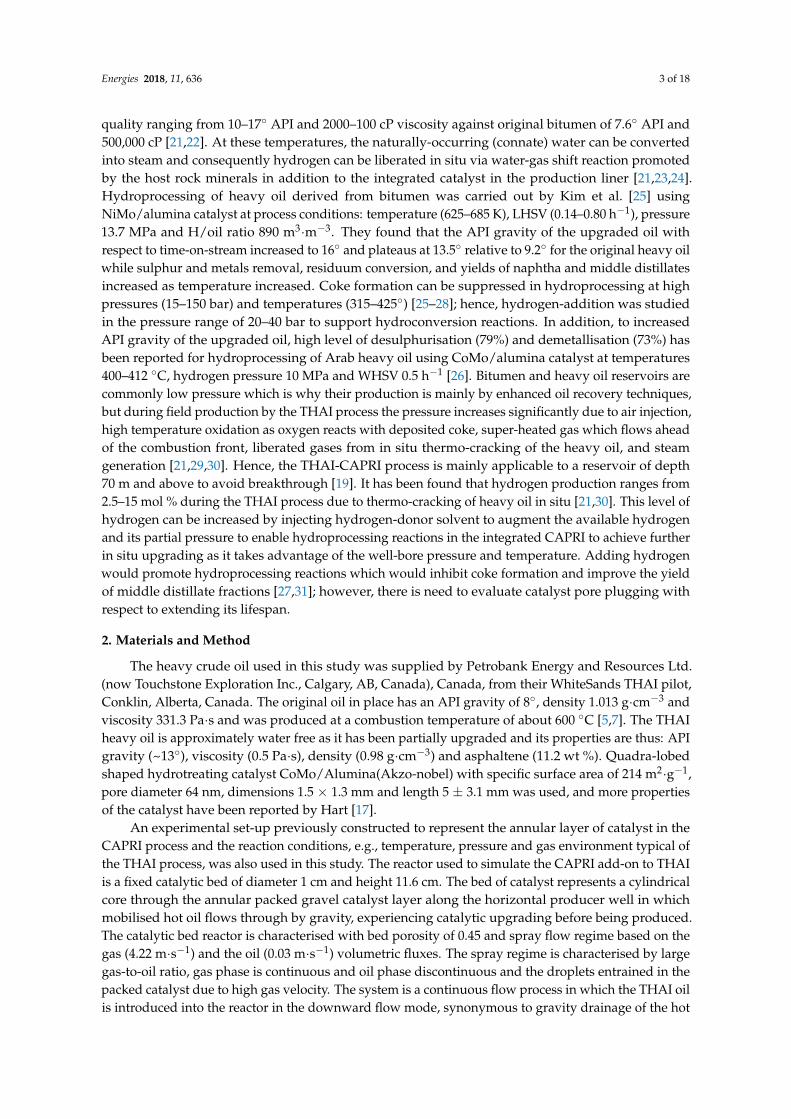
Figure 1. Upgraded oil (a) API gravity increase and (b) viscosity as a function time‐on‐stream at
temperature 425 °C, pressure 20 barg, LHSV 11.8 h−1 and GHSV 2353 h−1.
On average the upgraded oil API gravities are 3.1 ± 0.6° (nitrogen) and ~5 ± 0.5° (hydrogen)
above 13° for the THAI feed oil (Figure 1a). This represents approximately 2° increase attributable to
the addition of hydrogen. Similar results have been reported in references [12–15].
The absolute viscosities of the upgraded oils are 0.093 Pa∙s (nitrogen) and 0.075 Pa∙s (hydrogen)
compared to the 0.5 Pa∙s (THAI feed oil). This represents approximately 81% and 85% viscosity
Figure 1. Upgraded oil (a) API gravity increase and (b) viscosity as a function time-on-stream attemperature 425 ◦C, pressure 20 barg, LHSV 11.8 h−1 and GHSV 2353 h−1.
On average the upgraded oil API gravities are 3.1 ± 0.6◦ (nitrogen) and ~5 ± 0.5◦ (hydrogen)above 13◦ for the THAI feed oil (Figure 1a). This represents approximately 2◦ increase attributable tothe addition of hydrogen. Similar results have been reported in references [12–15].
Energies 2018, 11, 636 6 of 18
The absolute viscosities of the upgraded oils are 0.093 Pa·s (nitrogen) and 0.075 Pa·s (hydrogen)compared to the 0.5 Pa·s (THAI feed oil). This represents approximately 81% and 85% viscosityreductions under nitrogen and hydrogen, respectively (Figure 1b). Wang et al. [33] ascribed the slightlyfurther reduction of viscosity observed under hydrogen environment to HDS and hydrogenationreactions, which potentially increased the amount of light hydrocarbons produced compared to whennitrogen was used. It has been reported that significant amounts of hydrogen and hydrogen-rich gasessuch as H2, CH4 and C2H6 were stripped off from the heavy crude oil into the gas phase [13,15]; thusthe upgrading achieved under a nitrogen environment can therefore be ascribed to carbon-rejection dueto cracking of macromolecular weight species such as resins and asphaltenes. The radical fragmentsfrom the cracked macromolecules can readily regroup to form large hydrocarbon compounds, whilstunder hydrogen environment these free radicals are readily scavenged by active hydrogen to formlower molecular weight hydrocarbons [13].
At a significance level of 0.05 (5%), the one-tailed probability-value (p-value) of a Z-test for theexperimental data at the hypothesized dataset mean of 4◦ API gravity and 0.08 Pa·s. under nitrogenenvironment, the p-value is 0.9997 and with hydrogen environment it is 0.0149. Since the p-value,0.0149 (under H2), is less than 0.05, the null hypothesis (mean = 4◦ API) is rejected in favour of thealternative, that is the upgraded oil API gravity is greater than 4◦. For the viscosity, while the p-value,0.0348 (under N2) is less than 0.05, rejecting the null hypothesis of equal to 0.08 Pa·s, the p-value of0.7696 (under H2) favours it. This implies the viscosity of the upgraded oil under H2 is either less thanor equal to 0.08 Pa·s.
3.2. Effect of Hydrogen Pressure on Upgraded Oil API Gravity and Viscosity
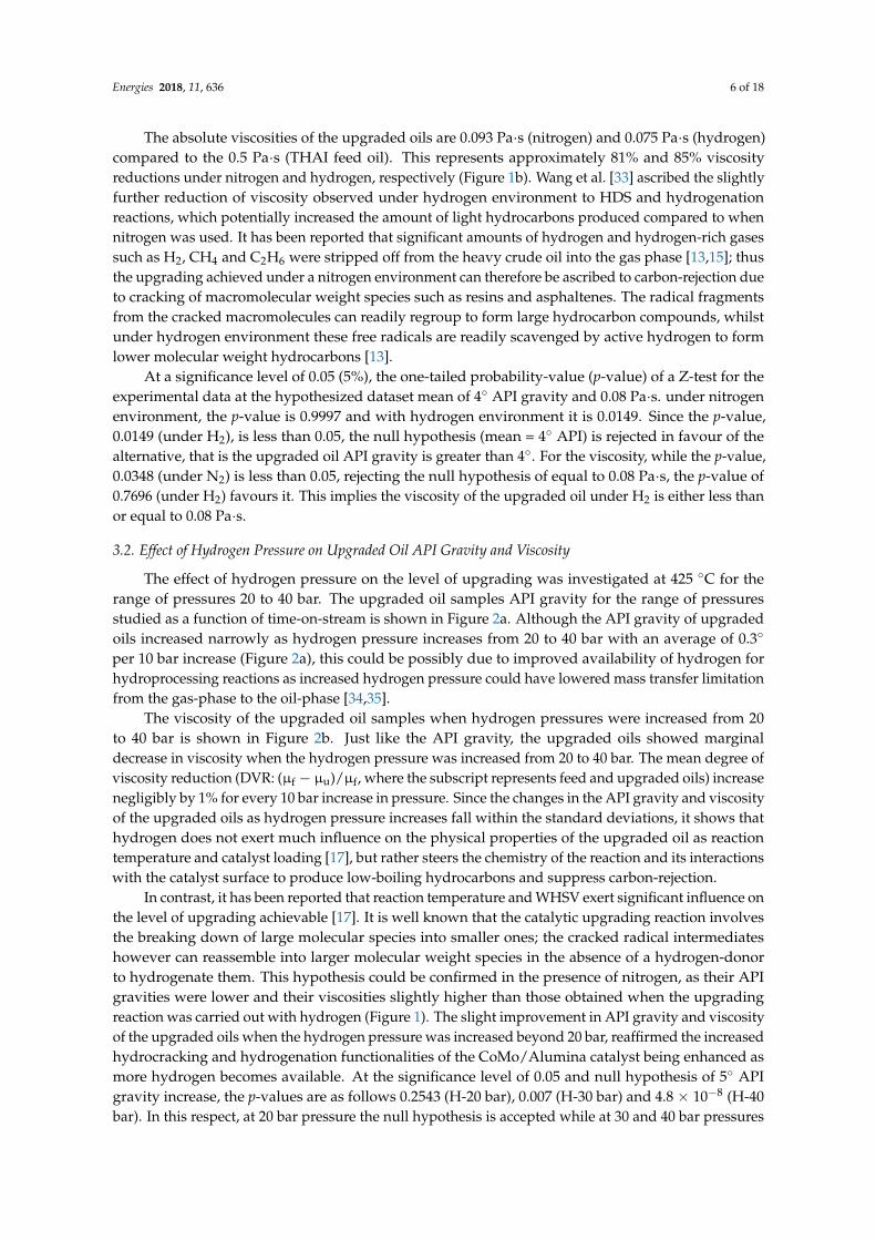
The effect of hydrogen pressure on the level of upgrading was investigated at 425 ◦C for therange of pressures 20 to 40 bar. The upgraded oil samples API gravity for the range of pressuresstudied as a function of time-on-stream is shown in Figure 2a. Although the API gravity of upgradedoils increased narrowly as hydrogen pressure increases from 20 to 40 bar with an average of 0.3◦
per 10 bar increase (Figure 2a), this could be possibly due to improved availability of hydrogen forhydroprocessing reactions as increased hydrogen pressure could have lowered mass transfer limitationfrom the gas-phase to the oil-phase [34,35].
The viscosity of the upgraded oil samples when hydrogen pressures were increased from 20to 40 bar is shown in Figure 2b. Just like the API gravity, the upgraded oils showed marginaldecrease in viscosity when the hydrogen pressure was increased from 20 to 40 bar. The mean degree ofviscosity reduction (DVR: (µf − µu)/µf, where the subscript represents feed and upgraded oils) increasenegligibly by 1% for every 10 bar increase in pressure. Since the changes in the API gravity and viscosityof the upgraded oils as hydrogen pressure increases fall within the standard deviations, it shows thathydrogen does not exert much influence on the physical properties of the upgraded oil as reactiontemperature and catalyst loading [17], but rather steers the chemistry of the reaction and its interactionswith the catalyst surface to produce low-boiling hydrocarbons and suppress carbon-rejection.
In contrast, it has been reported that reaction temperature and WHSV exert significant influence onthe level of upgrading achievable [17]. It is well known that the catalytic upgrading reaction involvesthe breaking down of large molecular species into smaller ones; the cracked radical intermediateshowever can reassemble into larger molecular weight species in the absence of a hydrogen-donorto hydrogenate them. This hypothesis could be confirmed in the presence of nitrogen, as their APIgravities were lower and their viscosities slightly higher than those obtained when the upgradingreaction was carried out with hydrogen (Figure 1). The slight improvement in API gravity and viscosityof the upgraded oils when the hydrogen pressure was increased beyond 20 bar, reaffirmed the increasedhydrocracking and hydrogenation functionalities of the CoMo/Alumina catalyst being enhanced asmore hydrogen becomes available. At the significance level of 0.05 and null hypothesis of 5◦ APIgravity increase, the p-values are as follows 0.2543 (H-20 bar), 0.007 (H-30 bar) and 4.8 × 10⁻⁸ (H-40bar). In this respect, at 20 bar pressure the null hypothesis is accepted while at 30 and 40 bar pressures

Energies 2018, 11, 636 7 of 18
the API gravity increases are most likely to be greater than 5◦ API gravity increase. Conversely, witha null hypothesis of 0.06 Pa·s for the upgraded oil viscosity, the p-values are 0.798 (H-20 bar), 0.998(H-30 bar), and 0.9999 (H-40 bar), respectively.
Energies 2018, 11, x FOR PEER REVIEW 7 of 18
upgraded oil viscosity, the p‐values are 0.798 (H‐20 bar), 0.998 (H‐30 bar), and 0.9999 (H‐40 bar),
respectively.
Maipur et al. [36] proposed an empirical equation for estimating hydrogen consumption, in this
study however the outlet hydrogen flow was not measured; hence, the total hydrogen uptake in
moles during the upgrading reactions was not calculated. However, hydrogen concentrations in the
outlet gas phase decreased by 13.3% (20 bar), 17.33% (30 bar), and 19.83% (40 bar) relative to 99.99%
pure hydrogen fed. This is indicative of hydrogen involvement in hydroprocessing reactions, which
increases as pressure increases [37–40].
Figure 2. Effect of hydrogen pressure on (a) the upgraded oil API gravity and (b) the upgraded oil
viscosity as a function of time‐on‐stream.
3.3. Upgraded Oils True Boiling Point (TBP) Distribution
Simulated distillation was used to derive the TBP curves, which are indicative of the shift in
boiling fractions of the produced oil that has occurred as a result of the upgrading reactions. The TBP
Figure 2. Effect of hydrogen pressure on (a) the upgraded oil API gravity and (b) the upgraded oilviscosity as a function of time-on-stream.
Maipur et al. [36] proposed an empirical equation for estimating hydrogen consumption, in thisstudy however the outlet hydrogen flow was not measured; hence, the total hydrogen uptake inmoles during the upgrading reactions was not calculated. However, hydrogen concentrations in theoutlet gas phase decreased by 13.3% (20 bar), 17.33% (30 bar), and 19.83% (40 bar) relative to 99.99%pure hydrogen fed. This is indicative of hydrogen involvement in hydroprocessing reactions, whichincreases as pressure increases [37–40].

Energies 2018, 11, 636 8 of 18
3.3. Upgraded Oils True Boiling Point (TBP) Distribution
Simulated distillation was used to derive the TBP curves, which are indicative of the shift inboiling fractions of the produced oil that has occurred as a result of the upgrading reactions. TheTBP distribution curves for the THAI feed and upgraded oil samples obtained at hydrogen pressuresof 20–40 bar and that obtained under nitrogen (20 bar) are shown in Figure 3. It is clear that theupgraded oils contain more fuel fractions such as naphtha (Initial Boiling Point, IBP—177 ◦C) andmiddle distillates (177–343 ◦C) compared to the THAI feed oil. Consequently, the upgraded oil in thepresence of hydrogen distilled more naphtha and middle distillate fractions compared to that achievedwhen the upgrading reaction was performed with nitrogen. This improved yield of fuel fractions withhydrogen is consistent with that recorded on the API gravity and viscosity shown in Figure 1.
Energies 2018, 11, x FOR PEER REVIEW 8 of 18
distribution curves for the THAI feed and upgraded oil samples obtained at hydrogen pressures of
20–40 bar and that obtained under nitrogen (20 bar) are shown in Figure 3. It is clear that the
upgraded oils contain more fuel fractions such as naphtha (Initial Boiling Point, IBP—177 °C) and
middle distillates (177–343 °C) compared to the THAI feed oil. Consequently, the upgraded oil in the
presence of hydrogen distilled more naphtha and middle distillate fractions compared to that
achieved when the upgrading reaction was performed with nitrogen. This improved yield of fuel
fractions with hydrogen is consistent with that recorded on the API gravity and viscosity shown in
Figure 1.
Figure 3. The TBP distribution of the THAI feed and upgraded oil.
On the effect of hydrogen pressure on the TBP distribution, it can be observed that the
composition of the upgraded oils for the hydrogen pressure range of 20–40 bar was approximately
identical for the naphtha fractions (IBP—177 °C). However, the upgraded oil at 30 bar hydrogen
pressure produced more middle distillate fractions (177–343 °C) and less residue fraction (343 °C+)
compared to those achieved when the upgrading reactions were carried out at 20 and 40 bars
respectively. In summary, the upgraded oil with hydrogen contained more low‐boiling hydrocarbon
components, followed by the upgraded oil obtained when nitrogen gas was used relative to the
THAI oil studied. Jarullah and co‐workers [41] reported hydrotreatment of conventional crude oil in
a trickle‐bed reactor, from which they deduced that the yield of middle distillate fractions increased
thereafter. This can be attributed to hydrocracking, hydrogenation of free radicals, aromatics and
olefins, and the removal of heteroatoms.
The conversion of residue fractions (343 °C+) was calculated [(343 °C+f − 343 °C+u)/343 °C+f]. It
was found that for nitrogen atmosphere the conversion was 37.4% and hydrogen 44.1% at 425 °C
and gas pressure of 20 bar, while further increase in hydrogen pressure resulted in 52.5% (30 bar)
and 41.2% (40 bar). This represents 6.7–15.1% above that of nitrogen, which further confirmed the
participation of hydrogen in the upgrading reactions. In contrast, unlike the physical properties of
the upgraded oil which shows no appreciable difference in API gravity and viscosity in spite of the
increasing hydrogen pressure (Figure 2), the TBP curves and the residue fraction (343 °C+)
conversion show an appreciable difference outside of the margin of the standard deviation when the
pressure was increased. This is because while cracking which breaks heavy molecules into small
ones results in huge changes in physical properties of the produced oil is temperature dependent,
the pressure influences mainly the hydrogenation reaction without bond cleavage. This is consistent
with the observed increased middle distillate fractions as hydrogen pressure increased [27,28]. The
Figure 3. The TBP distribution of the THAI feed and upgraded oil.
On the effect of hydrogen pressure on the TBP distribution, it can be observed that the compositionof the upgraded oils for the hydrogen pressure range of 20–40 bar was approximately identical for thenaphtha fractions (IBP—177 ◦C). However, the upgraded oil at 30 bar hydrogen pressure producedmore middle distillate fractions (177–343 ◦C) and less residue fraction (343 ◦C+) compared to thoseachieved when the upgrading reactions were carried out at 20 and 40 bars respectively. In summary,the upgraded oil with hydrogen contained more low-boiling hydrocarbon components, followed bythe upgraded oil obtained when nitrogen gas was used relative to the THAI oil studied. Jarullah andco-workers [41] reported hydrotreatment of conventional crude oil in a trickle-bed reactor, from whichthey deduced that the yield of middle distillate fractions increased thereafter. This can be attributed tohydrocracking, hydrogenation of free radicals, aromatics and olefins, and the removal of heteroatoms.
The conversion of residue fractions (343 ◦C+) was calculated [(343 ◦C+f − 343 ◦C+u)/343 ◦C+f].It was found that for nitrogen atmosphere the conversion was 37.4% and hydrogen 44.1% at 425 ◦Cand gas pressure of 20 bar, while further increase in hydrogen pressure resulted in 52.5% (30 bar)and 41.2% (40 bar). This represents 6.7–15.1% above that of nitrogen, which further confirmed theparticipation of hydrogen in the upgrading reactions. In contrast, unlike the physical properties ofthe upgraded oil which shows no appreciable difference in API gravity and viscosity in spite of theincreasing hydrogen pressure (Figure 2), the TBP curves and the residue fraction (343 ◦C+) conversionshow an appreciable difference outside of the margin of the standard deviation when the pressure

Energies 2018, 11, 636 9 of 18
was increased. This is because while cracking which breaks heavy molecules into small ones resultsin huge changes in physical properties of the produced oil is temperature dependent, the pressureinfluences mainly the hydrogenation reaction without bond cleavage. This is consistent with theobserved increased middle distillate fractions as hydrogen pressure increased [27,28]. The Co andMo metals on the catalyst surface were responsible for this hydrogenation functionality while acidsites of the alumina support facilitated the cracking of the macromolecular weight species. Hence,hydroprocessing reactions dominate the catalytic upgrading reactions under hydrogen atmosphereand favourable partial pressures. Shah et al. [10] showed that pressure has little or no effect on thelevel of upgrade under nitrogen environment.
3.4. Upgraded Oil Asphaltene and Spent Catalyst Coke Contents
Asphaltenes are among the largest and heaviest polar component of heavy oil and thus are readilydeposited upon catalyst surfaces as coke-precursors. Being a major contributor to coke formation,hydrogenating radicals formed when they are cracked could reduce the asphaltene content of theproduced oil and potentially lead to a longer catalyst lifetime. The asphaltene content of the upgradedoil samples can be summarised as thus 8.6 ± 0.6 (N2, 20 bar), 7.8 ± 0.4 (H2, 20 bar), 5.7 ± 0.3 (H2,30 bar), and 5.8 ± 0.4 (H2, 40 bar) compared to 11.2 wt % (THAI feed oil). Though the asphaltenecontents of the upgraded oils were lower than that of the THAI oil, the presence of hydrogen furtherdecreased it due to the hydrogenation of cracked fragments which is rarely experienced in the presenceof nitrogen. This reaction involves hydrogen transfer from the gas-phase to the macromolecularradicals in the oil phase, which is possible under high reaction temperatures such as 425 ◦C and highhydrogen pressure [42,43].
The coke contents of the recovered catalyst after experiment with nitrogen (20 bar) and hydrogen(20 to 40 bar) as determined using TGA are presented in Figure 4. It has been reported that the burn-offbeyond 600 ◦C represents coke [44]. The thermogram (TG), that is weight loss with temperature andits differential (DTG) curves show that the coke formation under nitrogen environment is higher(35.4 wt %) compared to hydrogen (27.2 wt %).
With increasing hydrogen pressure from 20 to 40 bar, it was observed that the catalyst coke contentdecreased from 27.2 to 17.3 wt %, signifying that coke formation under hydrogen environment wassensitive to pressure. Hence, the activity of the catalyst can be sustained long enough compared toabout 90 h observed by Shah et al. [10] with nitrogen environment, as the susceptibility of the catalystto coke fouling has been decreased with hydrogen, following the lower coke formation observedcompared to when nitrogen was used.
Zhang and Shaw [45] and Matsumura et al. [46] observed a similar trend in coke content of thecatalyst as hydrogen pressure was increased. Thus, increasing the hydrogen pressure could haveimproved the transfer and the solubility of hydrogen in the oil-phase. Higher hydrogen pressureprovided more hydrogen in the vicinity of the catalyst surface, which is thermodynamically favourablefor hydroprocessing reactions considering the reaction temperature of 425 ◦C [36,37,47].
The TGA only quantifies the total amount of coke deposited on the catalyst after 11 h of experiment;to comprehend the extent of pore plugging mercury porosimetry and nitrogen adsorption-desorptionwere used. The catalyst pore size distribution before and after 11 h of upgrading reactions undernitrogen and hydrogen is shown in Figure 5. Figure 6 shows the nitrogen adsorption-desorptionisotherm for the fresh and spent CoMo/Alumina catalyst. It can be observed that less coke wasformed with hydrogen-addition (Figures 4 and 5), while the entire pores of the catalyst afterreaction under nitrogen was utterly plugged (Figure 5). A narrow pore size distribution can beobserved after the upgrading reaction under hydrogen. Similar observation using the nitrogenadsorption-desorption isotherm after upgrading reactions under hydrogen and nitrogen has beenreported by Hart et al. [12,13]. This observation reaffirmed the suppression of coke formation viahydroporcessing reactions such as hydrocracking, hydrotreating, and hydrogenation of intermediateradicals, olefins, and polynuclear aromatics once they are formed [48,49].

Energies 2018, 11, 636 10 of 18
Energies 2018, 11, x FOR PEER REVIEW 9 of 18
Co and Mo metals on the catalyst surface were responsible for this hydrogenation functionality
while acid sites of the alumina support facilitated the cracking of the macromolecular weight
species. Hence, hydroprocessing reactions dominate the catalytic upgrading reactions under
hydrogen atmosphere and favourable partial pressures. Shah et al. [10] showed that pressure has
little or no effect on the level of upgrade under nitrogen environment.
3.4. Upgraded Oil Asphaltene and Spent Catalyst Coke Contents
Asphaltenes are among the largest and heaviest polar component of heavy oil and thus are
readily deposited upon catalyst surfaces as coke‐precursors. Being a major contributor to coke
formation, hydrogenating radicals formed when they are cracked could reduce the asphaltene
content of the produced oil and potentially lead to a longer catalyst lifetime. The asphaltene content
of the upgraded oil samples can be summarised as thus 8.6 ± 0.6 (N2, 20 bar), 7.8 ± 0.4 (H2, 20 bar), 5.7
± 0.3 (H2, 30 bar), and 5.8 ± 0.4 (H2, 40 bar) compared to 11.2 wt % (THAI feed oil). Though the
asphaltene contents of the upgraded oils were lower than that of the THAI oil, the presence of
hydrogen further decreased it due to the hydrogenation of cracked fragments which is rarely
experienced in the presence of nitrogen. This reaction involves hydrogen transfer from the gas‐phase
to the macromolecular radicals in the oil phase, which is possible under high reaction temperatures
such as 425 °C and high hydrogen pressure [42,43].
The coke contents of the recovered catalyst after experiment with nitrogen (20 bar) and
hydrogen (20 to 40 bar) as determined using TGA are presented in Figure 4. It has been reported that
the burn‐off beyond 600 °C represents coke [44]. The thermogram (TG), that is weight loss with
temperature and its differential (DTG) curves show that the coke formation under nitrogen
environment is higher (35.4 wt %) compared to hydrogen (27.2 wt %).
With increasing hydrogen pressure from 20 to 40 bar, it was observed that the catalyst coke
content decreased from 27.2 to 17.3 wt %, signifying that coke formation under hydrogen
environment was sensitive to pressure. Hence, the activity of the catalyst can be sustained long
enough compared to about 90 h observed by Shah et al. [10] with nitrogen environment, as the
susceptibility of the catalyst to coke fouling has been decreased with hydrogen, following the lower
coke formation observed compared to when nitrogen was used.
Figure 4. Thermogram of the recovered catalyst after experiment under N2 and H2 (20–40 bar).
Standard deviations ±2.6 wt % (N2), ±1.8 wt % (H2, 20 bar), ±1.1 wt % (H2, 30 bar) and 1.3 wt % (H2, 40
bar).
Figure 4. Thermogram of the recovered catalyst after experiment under N2 and H2 (20–40 bar).Standard deviations ±2.6 wt % (N2), ±1.8 wt % (H2, 20 bar), ±1.1 wt % (H2, 30 bar) and 1.3 wt % (H2,40 bar).
Energies 2018, 11, x FOR PEER REVIEW 10 of 18
Zhang and Shaw [45] and Matsumura et al. [46] observed a similar trend in coke content of the
catalyst as hydrogen pressure was increased. Thus, increasing the hydrogen pressure could have
improved the transfer and the solubility of hydrogen in the oil‐phase. Higher hydrogen pressure
provided more hydrogen in the vicinity of the catalyst surface, which is thermodynamically
favourable for hydroprocessing reactions considering the reaction temperature of 425 °C [36,37,47].
The TGA only quantifies the total amount of coke deposited on the catalyst after 11 hours of
experiment; to comprehend the extent of pore plugging mercury porosimetry and nitrogen
adsorption‐desorption were used. The catalyst pore size distribution before and after 11 hours of
upgrading reactions under nitrogen and hydrogen is shown in Figure 5. Figure 6 shows the nitrogen
adsorption‐desorption isotherm for the fresh and spent CoMo/Alumina catalyst. It can be observed
that less coke was formed with hydrogen‐addition (Figures 4 and 5), while the entire pores of the
catalyst after reaction under nitrogen was utterly plugged (Figure 5). A narrow pore size distribution
can be observed after the upgrading reaction under hydrogen. Similar observation using the
nitrogen adsorption‐desorption isotherm after upgrading reactions under hydrogen and nitrogen
has been reported by Hart et al. [12,13]. This observation reaffirmed the suppression of coke
formation via hydroporcessing reactions such as hydrocracking, hydrotreating, and hydrogenation
of intermediate radicals, olefins, and polynuclear aromatics once they are formed [48,49].
In Figure 6, the isotherm of the fresh CoMo/Alumina revealed it is type IV which is
characterised by meso‐pores with specific surface area of 214 m2∙g−1. Compared to the fresh catalyst,
the spent catalyst showed a remarkable drop in nitrogen adsorbed‐desorbed as the relative pressure
approached 1. This is indicative of loss in pore volume and porosity due to coke deposition; hence,
the specific surface areas were decreased to 59.4 m2∙g−1 (after upgrading with hydrogen) and 2.03
m2∙g−1 (after upgrading with nitrogen). While the spent catalyst after the upgrading reaction under
nitrogen environment experienced almost total loss of catalyst surface area and pore volume due to
high coke formation, which obtained with hydrogen experienced moderate loss of area and pore
volume, consistent with the TGA (Figure 4) and porosimetry (Figure 5).
Since the catalyst is less prone to pore plugging and loss of surface due to lower coke formation
when the upgrading reaction occurs under H‐rich environment, the catalytic activity is prolonged
significantly compared to N2 environment. Hence, the catalyst achieved an additional increase in
API gravity of 1–2° over that obtained when the experiment was carried out under N2 (Figure 1). The
reality is that this level of in situ partial upgrading with H2 is still valuable to oil industries as it is
worth approximately $0.5–$1.5 per API point and up to $9/barrel depending on oil price [8].
Figure 5. Mercury porosimetry of catalyst before and after experiment under N2 and H2 at 20 bar. Figure 5. Mercury porosimetry of catalyst before and after experiment under N2 and H2 at 20 bar.

Energies 2018, 11, 636 11 of 18Energies 2018, 11, x FOR PEER REVIEW 11 of 18
Figure 6. Nitrogen adsorption‐desorption isotherm for the fresh and spent CoMo/Alumina after
upgrading reaction under nitrogen and hydrogen environment.
Figure 5 also shows that significant upgrading would have occurred at the early hours of the
experiment as observed in Figure 1; before the catalyst pore channels were plugged, allowing only
the low molecular weight hydrocarbons to access the pores and then get cracked. Once the surface
and pores of the catalyst were covered by coke the level upgrading drops rapidly as noticed in
Figure 1, especially when the upgrading reaction was performed under nitrogen. Also, the
polynuclear aromatics adsorbed onto the external surface of catalyst, could prevent the optimum
utilisation of the internal surface of the catalyst when the upgrading reaction was carried out under
N2. The higher amount of coke formed under nitrogen environment compared to hydrogen (Figures
4 and 5), reaffirmed that the level of upgrading achieved with nitrogen can be attributed mainly to
carbon‐rejection (Figure 1).
The SEM photomicrograph of the catalyst was studied over an area of 2 μm widths and
magnification of 35,000×. Figure 7 shows the photomicrographs of the fresh and coked catalyst after
upgrading reactions in the presence of nitrogen and hydrogen. The surface morphology after
upgrading reactions shows carbonaceous deposits such as precipitated asphaltene and coke on the
surface of the catalyst.
The coke formed an amorphous encapsulate of the catalyst surface and revealed pore plugging.
It is clear that the catalyst experienced severe pore plugging and coking when the upgrading
reaction was carried out under nitrogen environment (Figure 7b) compared to when hydrogen was
used (Figure 7c). This reaffirmed the observations in Figures 4–6. Notably, the coke formed on the
surface of the catalyst after upgrading reactions under hydrogen environment was mostly spheroids
of size ranging from nano to micro‐meters globules, while when nitrogen was used; the coke was an
amorphous compact ground mass with few globules.
The effect of connate water on the catalyst was not investigated as the focus is mainly
deactivation due to coke deposition and catalyst pore plugging. Also, the heavy oil used in this
study as received from Petrobank Energy and Resources Ltd. is approximately free of water.
However, under field production at a temperature range of 400– 700 °C most of the connate water
will be converted into steam and with the aid of the catalyst and the rock minerals more hydrogen
can be produced through the water‐gas shift reaction (CO + H2O → H2 + CO2) and steam‐methane
reforming reaction (CH4 + H2O → CO + 3H2) [17,18,21]. Consequently, in addition to hydrogen being
expensive, it could be challenging to introduce it across the CAPRI zone. Hence, water is a potential
alternative source of hydrogen and its potential has been reported for heavy oil upgrading with
Figure 6. Nitrogen adsorption-desorption isotherm for the fresh and spent CoMo/Alumina afterupgrading reaction under nitrogen and hydrogen environment.
In Figure 6, the isotherm of the fresh CoMo/Alumina revealed it is type IV which is characterisedby meso-pores with specific surface area of 214 m2·g−1. Compared to the fresh catalyst, the spentcatalyst showed a remarkable drop in nitrogen adsorbed-desorbed as the relative pressure approached1. This is indicative of loss in pore volume and porosity due to coke deposition; hence, the specificsurface areas were decreased to 59.4 m2·g−1 (after upgrading with hydrogen) and 2.03 m2·g−1 (afterupgrading with nitrogen). While the spent catalyst after the upgrading reaction under nitrogenenvironment experienced almost total loss of catalyst surface area and pore volume due to highcoke formation, which obtained with hydrogen experienced moderate loss of area and pore volume,consistent with the TGA (Figure 4) and porosimetry (Figure 5).
Since the catalyst is less prone to pore plugging and loss of surface due to lower coke formationwhen the upgrading reaction occurs under H-rich environment, the catalytic activity is prolongedsignificantly compared to N2 environment. Hence, the catalyst achieved an additional increase in APIgravity of 1–2◦ over that obtained when the experiment was carried out under N2 (Figure 1). Thereality is that this level of in situ partial upgrading with H2 is still valuable to oil industries as it isworth approximately $0.5–$1.5 per API point and up to $9/barrel depending on oil price [8].
Figure 5 also shows that significant upgrading would have occurred at the early hours of theexperiment as observed in Figure 1; before the catalyst pore channels were plugged, allowing onlythe low molecular weight hydrocarbons to access the pores and then get cracked. Once the surfaceand pores of the catalyst were covered by coke the level upgrading drops rapidly as noticed inFigure 1, especially when the upgrading reaction was performed under nitrogen. Also, the polynucleararomatics adsorbed onto the external surface of catalyst, could prevent the optimum utilisation ofthe internal surface of the catalyst when the upgrading reaction was carried out under N2. Thehigher amount of coke formed under nitrogen environment compared to hydrogen (Figures 4and 5), reaffirmed that the level of upgrading achieved with nitrogen can be attributed mainly tocarbon-rejection (Figure 1).
The SEM photomicrograph of the catalyst was studied over an area of 2 µm widths andmagnification of 35,000×. Figure 7 shows the photomicrographs of the fresh and coked catalystafter upgrading reactions in the presence of nitrogen and hydrogen. The surface morphology after

Energies 2018, 11, 636 12 of 18
upgrading reactions shows carbonaceous deposits such as precipitated asphaltene and coke on thesurface of the catalyst.
Energies 2018, 11, x FOR PEER REVIEW 12 of 18
supercritical water, steam cracking, and catalytic aquathermolysis [50].The potential of the
CoMo/Alumina catalyst to promote hydrogen production from water through the water‐gas shift
reaction and simultaneously support hydroprocessing reactions by stabilizing the oil cracked while
suppressing coke formation has been reported in the literature [18].
Figure 7. SEM photomicrograph (a) fresh CoMo/Alumina; (b) spent CoMo/Alumina after upgrading
with N2 and (c) spent CoMo/Alumina after upgrading with H2.
Figure 8 depicts the intimate contact between the oil and the catalyst, which resulted in the
occurrence of the upgrading reaction as the hot oil and combustion gases, including hydrogen,
would flow across the catalyst bed taking advantage of the well‐bore pressure and temperature to
further crack the heavy oil. The cracked heavy hydrocarbons into lighter molecular weight
hydrocarbons led to the improved viscosity and API gravity of the upgraded oil (Figure 1), and as a
consequence coke was deposited on the catalyst as illustrated in Figure 8 and observed in
Figures 4–7. The rapid decrease in the upgraded oil API gravities presented in Figure 1a from
20–300 min can be attributed to catalyst deactivation due to coke deposit, as confirmed in
Figures 4–7 which is an indication of the heavy hydrocarbons being cracked into lower fraction
hydrocarbons [17,27]. Heavy metals (e.g., V, Ni, and Fe) and coke deposits have been reported by
Leyva et al. [27] as major contributors to catalyst deactivation due to the cracking of macromolecular
weight species containing heteroatom (e.g., S and N) and heavy metals such as V and Ni during
hydroprocessing of heavy oil as illustrated in Figure 8.
The cracking of the adsorbed macromolecular weight hydrocarbons on the catalyst surface is
aided by the support acid sites while the dissociated hydrogen proton (H•) reacts with a heteroatom
such as sulphur due to the hydrotreating functionality of the impregnated Co and Mo on the
support, and is removed as H2S [17,27]. The other fragments of active hydrocarbon intermediates
(i.e., R1 and R2) are hydrogenated to stable hydrocarbon molecules and released into the oil phase
while the coke and metallic sulphides are deposited on the surface of the catalyst [27]. The
organometallic hydrocarbons in the heavy oil deposits metals (e.g., V, Ni) on the surface of the
catalyst as metallic sulphides (MxSy) as illustrated in Figure 8 [27]. Hence, this reaction is dependent
Figure 7. SEM photomicrograph (a) fresh CoMo/Alumina; (b) spent CoMo/Alumina after upgradingwith N2 and (c) spent CoMo/Alumina after upgrading with H2.
The coke formed an amorphous encapsulate of the catalyst surface and revealed pore plugging.It is clear that the catalyst experienced severe pore plugging and coking when the upgrading reactionwas carried out under nitrogen environment (Figure 7b) compared to when hydrogen was used(Figure 7c). This reaffirmed the observations in Figures 4–6. Notably, the coke formed on the surfaceof the catalyst after upgrading reactions under hydrogen environment was mostly spheroids ofsize ranging from nano to micro-meters globules, while when nitrogen was used; the coke was anamorphous compact ground mass with few globules.
The effect of connate water on the catalyst was not investigated as the focus is mainly deactivationdue to coke deposition and catalyst pore plugging. Also, the heavy oil used in this study as receivedfrom Petrobank Energy and Resources Ltd. is approximately free of water. However, under fieldproduction at a temperature range of 400– 700 ◦C most of the connate water will be convertedinto steam and with the aid of the catalyst and the rock minerals more hydrogen can be producedthrough the water-gas shift reaction (CO + H2O→ H2 + CO2) and steam-methane reforming reaction(CH4 + H2O→ CO + 3H2) [17,18,21]. Consequently, in addition to hydrogen being expensive, it couldbe challenging to introduce it across the CAPRI zone. Hence, water is a potential alternative source ofhydrogen and its potential has been reported for heavy oil upgrading with supercritical water, steamcracking, and catalytic aquathermolysis [50]. The potential of the CoMo/Alumina catalyst to promotehydrogen production from water through the water-gas shift reaction and simultaneously supporthydroprocessing reactions by stabilizing the oil cracked while suppressing coke formation has beenreported in the literature [18].

Energies 2018, 11, 636 13 of 18
Figure 8 depicts the intimate contact between the oil and the catalyst, which resulted in theoccurrence of the upgrading reaction as the hot oil and combustion gases, including hydrogen, wouldflow across the catalyst bed taking advantage of the well-bore pressure and temperature to furthercrack the heavy oil. The cracked heavy hydrocarbons into lighter molecular weight hydrocarbonsled to the improved viscosity and API gravity of the upgraded oil (Figure 1), and as a consequencecoke was deposited on the catalyst as illustrated in Figure 8 and observed in Figures 4–7. The rapiddecrease in the upgraded oil API gravities presented in Figure 1a from 20–300 min can be attributed tocatalyst deactivation due to coke deposit, as confirmed in Figures 4–7 which is an indication of theheavy hydrocarbons being cracked into lower fraction hydrocarbons [17,27]. Heavy metals (e.g., V, Ni,and Fe) and coke deposits have been reported by Leyva et al. [27] as major contributors to catalystdeactivation due to the cracking of macromolecular weight species containing heteroatom (e.g., S andN) and heavy metals such as V and Ni during hydroprocessing of heavy oil as illustrated in Figure 8.
Energies 2018, 11, x FOR PEER REVIEW 13 of 18
on hydrogen availability and catalyst activity. However, in a hydrogen limited medium such as a
nitrogen environment, the intermediate fragments can readily aggregate to form bigger
hydrocarbon molecules, which explains why the upgraded oils under this environment have lower
API gravities and lower fuel distillate fractions compared to those obtained when the upgrading
reaction was carried out with hydrogen (Figures 1 and 3). As a consequence of starved hydrogen
when the reaction was carried out under nitrogen, the crack hydrocarbon radicals polymerised and
condensed into higher molecular weight species leading to higher coke formation and catalyst pore
plugging observed in Figures 5–7. Whilst under hydrogen the cracked radicals are stabilised into the
oil‐phase hence the upgraded oil has lower asphaltene component [13,17].
Figure 8. Typical interactions at catalyst surface for HDM and HDS reactions with hydrogen (metals
such Ni and V are removed as metallic sulphides (i.e., MxSy, M is metal) and R1 and R2 are
hydrocarbon intermediates).
Heavy oil is a complex mixture of different classes of hydrocarbons grouped into paraffins,
olefins, naphthenes, aromatics, hetero‐atomic compounds, and poly‐nuclear aromatics (e.g., resins
and asphaltenes). Figure 9 summarises generic pathways the different classes of hydrocarbons
found in the heavy oil would undergo depending on the reaction environment. Under nitrogen
environment, a higher amount of coke was observed as confirmed in Figures 4–7 as well as higher
catalyst deactivation can be noticed from 20–300 min in Figure 1 compared to when hydrogen was
used. These observations are possible if the reactions that result in coke formation are amplified
under nitrogen environment such as dehydrogenation, polymerisation, and condensation of
aromatics into polynuclear aromatics, including the cracking of macromolecular weight
hydrocarbons into lighter fractions. While cracking and ring opening are mostly temperature
dependent, hydrogenation, dehydrogenation and polymerisation/condensation are largely
promoted by the reaction environment under favourable pressure. As a consequence, olefins
produced by dehydrogenation of paraffins, thermal or catalytic cracking of the oil and the aromatics
fractions under nitrogen environment would have readily polymerised into larger molecular weight
compounds compared to when hydrogen was used.
Figure 8. Typical interactions at catalyst surface for HDM and HDS reactions with hydrogen (metalssuch Ni and V are removed as metallic sulphides (i.e., MxSy, M is metal) and R1 and R2 are hydrocarbonintermediates).
The cracking of the adsorbed macromolecular weight hydrocarbons on the catalyst surface is aidedby the support acid sites while the dissociated hydrogen proton (H•) reacts with a heteroatom such assulphur due to the hydrotreating functionality of the impregnated Co and Mo on the support, andis removed as H2S [17,27]. The other fragments of active hydrocarbon intermediates (i.e., R1 and R2)are hydrogenated to stable hydrocarbon molecules and released into the oil phase while the coke andmetallic sulphides are deposited on the surface of the catalyst [27]. The organometallic hydrocarbonsin the heavy oil deposits metals (e.g., V, Ni) on the surface of the catalyst as metallic sulphides (MxSy)as illustrated in Figure 8 [27]. Hence, this reaction is dependent on hydrogen availability and catalystactivity. However, in a hydrogen limited medium such as a nitrogen environment, the intermediatefragments can readily aggregate to form bigger hydrocarbon molecules, which explains why theupgraded oils under this environment have lower API gravities and lower fuel distillate fractionscompared to those obtained when the upgrading reaction was carried out with hydrogen (Figures 1and 3). As a consequence of starved hydrogen when the reaction was carried out under nitrogen, the

Energies 2018, 11, 636 14 of 18
crack hydrocarbon radicals polymerised and condensed into higher molecular weight species leadingto higher coke formation and catalyst pore plugging observed in Figures 5–7. Whilst under hydrogenthe cracked radicals are stabilised into the oil-phase hence the upgraded oil has lower asphaltenecomponent [13,17].
Heavy oil is a complex mixture of different classes of hydrocarbons grouped into paraffins,olefins, naphthenes, aromatics, hetero-atomic compounds, and poly-nuclear aromatics (e.g., resinsand asphaltenes). Figure 9 summarises generic pathways the different classes of hydrocarbonsfound in the heavy oil would undergo depending on the reaction environment. Under nitrogenenvironment, a higher amount of coke was observed as confirmed in Figures 4–7 as well as highercatalyst deactivation can be noticed from 20–300 min in Figure 1 compared to when hydrogen wasused. These observations are possible if the reactions that result in coke formation are amplifiedunder nitrogen environment such as dehydrogenation, polymerisation, and condensation of aromaticsinto polynuclear aromatics, including the cracking of macromolecular weight hydrocarbons intolighter fractions. While cracking and ring opening are mostly temperature dependent, hydrogenation,dehydrogenation and polymerisation/condensation are largely promoted by the reaction environmentunder favourable pressure. As a consequence, olefins produced by dehydrogenation of paraffins,thermal or catalytic cracking of the oil and the aromatics fractions under nitrogen environment wouldhave readily polymerised into larger molecular weight compounds compared to when hydrogenwas used.
Energies 2018, 11, x FOR PEER REVIEW 14 of 18
Figure 9. Classes of catalytic upgrading reaction pathways for large aliphatic, naphthenic, and
aromatic species in the heavy crude in the absence and presence of hydrogen.
On the other hand, the presence of hydrogen supported and promoted hydrocracking,
hydrogenation, and hydrotreating (HDS, HDN, and HDM) reactions, while nitrogen environment
favoured cracking, dehydrogenation, polymerisation, and condensation of aromatic ring reactions
which resulted in high carbon‐rejection as is observed in Figures 4–7. We have previously shown
that more aliphatic hydrocarbon and less olefinic gases were produced when the upgrading reaction
was performed under hydrogen environment compared to nitrogen [13]. This proves that in the
presence of nitrogen, hydrogenation is very limited and carbon‐rejection was dominant during the
upgrading process. This was affirmed by the presence of more hydrogen and H‐rich gases such as
methane and ethane in the gas‐phase [13,15], and as a consequence higher coke formation and
catalyst pore plugging was observed when nitrogen was used as was confirmed from the analysis of
the spent catalyst coke content and its pore plugging presented in Figures 4–7. However, with
hydrogen environment, hydroprocessing (i.e., hydrocracking, hydrogenation, and hydrotreating)
reactions were amplified as shown in Figure 9, including hydrogenation of free radicals, unsaturated
hydrocarbons, and aromatics which inhibited polymerisation reactions and increased the lighter
fractions of the upgraded oil. These promoted reaction pathways in Figure 9 due to the presence of
hydrogen contributed towards the additional 0.5–2° API increase observed in Figure 1 and the more
naphtha and middle distillate fuel fractions obtained upon simulated distillation presented in Figure
3 over those attained when nitrogen was used. Hence, the upgraded oils obtained with hydrogen
environment were lighter and richer in lower molecular weight hydrocarbons than those obtained
when nitrogen was used.
Figure 9. Classes of catalytic upgrading reaction pathways for large aliphatic, naphthenic, and aromaticspecies in the heavy crude in the absence and presence of hydrogen.
On the other hand, the presence of hydrogen supported and promoted hydrocracking,hydrogenation, and hydrotreating (HDS, HDN, and HDM) reactions, while nitrogen environmentfavoured cracking, dehydrogenation, polymerisation, and condensation of aromatic ring reactions

Energies 2018, 11, 636 15 of 18
which resulted in high carbon-rejection as is observed in Figures 4–7. We have previously shown thatmore aliphatic hydrocarbon and less olefinic gases were produced when the upgrading reaction wasperformed under hydrogen environment compared to nitrogen [13]. This proves that in the presenceof nitrogen, hydrogenation is very limited and carbon-rejection was dominant during the upgradingprocess. This was affirmed by the presence of more hydrogen and H-rich gases such as methane andethane in the gas-phase [13,15], and as a consequence higher coke formation and catalyst pore pluggingwas observed when nitrogen was used as was confirmed from the analysis of the spent catalyst cokecontent and its pore plugging presented in Figures 4–7. However, with hydrogen environment,hydroprocessing (i.e., hydrocracking, hydrogenation, and hydrotreating) reactions were amplified asshown in Figure 9, including hydrogenation of free radicals, unsaturated hydrocarbons, and aromaticswhich inhibited polymerisation reactions and increased the lighter fractions of the upgraded oil. Thesepromoted reaction pathways in Figure 9 due to the presence of hydrogen contributed towards theadditional 0.5–2◦ API increase observed in Figure 1 and the more naphtha and middle distillate fuelfractions obtained upon simulated distillation presented in Figure 3 over those attained when nitrogenwas used. Hence, the upgraded oils obtained with hydrogen environment were lighter and richer inlower molecular weight hydrocarbons than those obtained when nitrogen was used.
4. Conclusions
The role of hydrogen in downhole catalytic upgrading of heavy crude was investigated at 425 ◦C,LHSV 11.8 h−1, and 20–40 bars which are within the hydroprocessing range. It was found that thecatalytic upgrading under nitrogen improved the API gravity of the upgraded oil by 3◦ on average,and the quality of the produced oil was further improved by 2◦ when the upgrading reaction wascarried out under hydrogen environment above 13◦ (THAI feed oil). The fluidity of upgraded oil forpipeline transportation was increased by approximately 83% compared to 0.5 Pa·s (THAI feed oil)irrespective of the reaction environment. Consequently, the upgraded oil with hydrogen environmentcontains greater quantities of hydrocarbons that can be converted into transport fuels upon distillationthan that obtained with nitrogen.
The coke formation and its consequence of pore plugging is a major cause of catalyst deactivation.While the catalyst pores were completely plugged after the upgrading reaction under nitrogenenvironment with coke content of 35.4 wt %, the catalyst benefited from less proneness to cokefouling and lower pore plugging when the upgrading reaction was carried out with hydrogen whichhad a coke content of 27.2 wt %. Since the catalyst was less susceptible to pore plugging due to lesscoke formation when hydrogen was used, the catalytic activity was prolonged, which is reflected onthe upgraded oil API gravity being approximately 0.5–2◦ higher than that obtained when nitrogenwas used after 11 h time-on-stream experiment. This fouling effect due to coke formation was furtherreduced by about 9 wt % as the hydrogen pressure increased from 20 to 40 bar.
In the reservoir, this hydrogen environment and its partial pressure can be achieved byaugmenting the hydrogen liberated from the in situ thermal cracking of the heavy oil by eitheroperating the THAI-CAPRI process under wet combustion to liberate hydrogen in situ through thewater-gas-shift reaction, since temperatures of 400–700 ◦C can be achieved by in situ combustion, or byintroducing a hydrogen-donor solvent. However, Petrobank Energy and Resources Ltd. found that themobilised hot temperatures range from +100 ◦C to 400 ◦C [21], in which temperatures below 400 ◦C areinsufficient to sustain catalytic cracking in the CAPRI zone. Therefore, future outlook to circumventthis challenge will be to heat the CAPRI zone electromagnetically such as induction heating sincemagnetic fields can permeate the formation in order to augment and create a uniform temperature of425 ◦C.
Acknowledgments: We would like to acknowledge the Petroleum Technology Development Fund (PTDF),Nigeria, the scholarship for Abarasi Hart and the Engineering and Physical Science Research Council (EPSRC)with Grant Nos.EP/E057977/1, EP/J008303/1 and EP/N032985/1, United Kingdom. The THAI oil was suppliedby Petrobank Energy and Resources, Ltd. (now Touchstone Exploration Inc.), Canada.

Energies 2018, 11, 636 16 of 18
Author Contributions: Joseph Wood and Abarasi Hart conceived and designed the experiments which resultsare reported here; Abarasi Hart performed the experiments and analysed the data under the supervision ofJoseph Wood; the materials and analytical tools used in the experiments were provided by the EPSRC (PrincipalInvestigator Joseph Wood); Abarasi Hart wrote the initial draft of the paper which was significantly reviewed byJoseph Wood.
Conflicts of Interest: The authors declare no conflict of interest. The authors declare no competingfinancial interest.
Data Access: Data sets from the above work are available via epapers.bham.ac.uk.
Nomenclature
THAI Toe-to-Heel Air InjectionCAPRI CAtalytc upgrading PRocess In situHDS HydrodesulphurisationHDN HydrodenitrogenationHDM HydrodemetallisationTBP True Boiling PointIBP Initial Boiling PointTGA Thermogravimetric AnalysisDTG Differential ThermogravimetricDVR Degree of Viscosity ReductionLHSV Liquid Hourly Space VelocityGHSV Gas Hourly Space VelocityWHSV Weight Hourly Space VelocityAPI American Petroleum InstituteSEM Scanning Electron Microscope
References
1. Sawatdeenarunat, C.; Nguyen, D.; Surendra, K.C.; Shrestha, S.; Rajendran, K.; Oechsner, H.; Xie, L.;Khanal, K.S. Anaerobibiorefinery: Current status, challenges and opportunities. Bioresour. Technol. 2016, 215,304–313. [CrossRef] [PubMed]
2. Zitha, P.; Felder, R.; Zornes, D.; Brown, K.; Mohanty, K. Increasing Hydrocarbon Recovery Factors. 2011.Available online: http://www.spe.org/industry/increasing-hydrocarbon-recovery-factors.php (accessed on13 November 2017).
3. Hein, J.F. Geology of bitumen and heavy oil: An overview. J. Pet. Sci. Eng. 2017, 154, 551–563. [CrossRef]4. Upreti, S.R.; Lohi, A.; Kapadia, R.A.; El-Ha, R. Vapor extraction of heavy oil and bitumen: A review. Energy
Fuels 2007, 21, 1562–1574. [CrossRef]5. Xia, T.M.; Greaves, M.; Werfilli, W.S.; Rathbone, R.R. Downhole conversion of Lloydminster heavy oil using
THAI-CAPRI process. In Proceedings of the SPE/PS-CIM/CHOA International Thermal Operations andHeavy Oil Symposium and International Horizontal Well Technology Conference, Calgary, AB, Canada,4–7 November 2002.
6. Guo, K.; Zhang, Y.; Shi, Q.; Yu, Z. The effect of carbon-supported nickel nanoparticles in the reduction ofcarboxylic acids for in situ upgrading of heavy crude. Energy Fuels 2017. [CrossRef]
7. Xia, T.X.; Greaves, M. 3-D physical model studies of downhole catalytic upgrading of Wolf Lake heavy oilusing THAI. In Proceedings of the Petroleum Society’s Canadian International Petroleum Conference 2001,Calgary, AB, Canada, 12–14 June 2001; Paper 2001-17.
8. Ayasse, C.; Greaves, M.; Turta, A. Oilfield In Situ Hydrocarbon Upgrading Process. U.S. Patent 6,412,557 B1,2 July 2002.
9. Hassanzadeh, H.; Abedi, J. Modelling and parameter estimation of ultra-dispersed in situ catalytic upgradingexperiments in a batch reactor. Fuel 2010, 89, 2822–2828. [CrossRef]
10. Shah, A.; Fishwick, R.P.; Leeke, G.A.; Wood, J.; Rigby, S.P.; Greaves, M. Experimental optimisation of catalyticprocess in situ for heavy-oil and bitumen upgrading. J. Can. Pet. Technol. 2011, 50, 33–47. [CrossRef]

Energies 2018, 11, 636 17 of 18
11. Galarraga, E.C.; Scott, C.; Loria, H.; Pereira-Almao, P. Kinetic models for upgrading Athabasca bitumenusing unsupported NiWMo catalyst at low severity conditions. Ind. Eng. Chem. Res. 2012, 51, 140–146.[CrossRef]
12. Hart, A.; Shah, A.; Leeke, G.; Greaves, M.; Wood, J. Optimization of the CAPRI process for heavy oilupgrading: Effect of hydrogen and guard bed. Ind. Eng. Chem. Res. 2013, 52, 15394–15406. [CrossRef]
13. Hart, A.; Leeke, G.; Greaves, M.; Wood, J. Downhole heavy crude oil upgrading using CAPRI: Effect ofhydrogen and methane gases upon upgrading and coke formation. Fuel 2014, 119, 226–235. [CrossRef]
14. Hart, A.; Wood, J.; Greaves, M. In Situ Catalytic Upgrading of Heavy Oil Using a Pelletized Ni-Mo/Al2O3
Catalyst in the THAI Process. J. Pet. Sci. Eng. 2017, 156, 958–965. [CrossRef]15. Hart, A.; Wood, J.; Greaves, M. Laboratory Investigation of CAPRI Catalytic THAI-add-on Process for Heavy
Oil Production and In Situ Upgrading. J. Anal. Appl. Pyrolysis 2017. [CrossRef]16. Al-Marshed, A.; Hart, A.; Leeke, G.; Greaves, M.; Wood, J. Effectiveness of Different Transition Metal
Dispersed Catalysts for In Situ Heavy Oil Upgrading. Ind. Eng. Chem. Res. 2015, 54, 10645–10655. [CrossRef]17. Hart, A. Advanced Studies of Catalytic Upgrading of Heavy Oils. Ph.D. Thesis, University of Birmingham,
Birmingham, UK, 2014.18. Hart, A.; Leeke, G.; Greaves, M.; Wood, J. Downhole heavy crude oil upgrading using CAPRI: Effect of
steam upon upgrading and coke formation. Energy Fuels 2014, 8, 1811–1819. [CrossRef]19. Hart, A.; Greaves, M.; Wood, J. A comparative study of fixed-bed and dispersed catalytic upgrading of heavy
crude oil using-CAPRI. Chem. Eng. J. 2015, 282, 213–223. [CrossRef]20. Hart, A.; Lewis, C.; White, T.; Greaves, M.; Wood, J. Effect of cyclohexane as hydrogen-donor in
ultradispersed catalytic upgrading of heavy oil. Fuel Process. Technol. 2015, 138, 724–733. [CrossRef]21. Annual Report of the Petrobank Energy and Resources Ltd. 2007. Available online: https://www.knotia.ca/
kstore/productinfo/fric08/PDFs/Petrobank%20Energy%20and%20Resources%20Ltd.%20AR_2007.pdf(accessed on 28 February 2018).
22. Xia, T.X.; Greaves, M. Upgrading Athabasca Tar Sand Using Toe-to-Heel Air Injection. In Proceedings of the2000 SPE/Petroleum Society of CIM International Conference on Horizontal Well Technology, Calgary, AB,Canada, 6–8 November 2000.
23. Maity, S.K.; Ancheyta, J.; Marroquın, G. Catalytic Aquathermolysis Used for Viscosity Reduction of HeavyCrude Oils: A Review. Energy Fuels 2010, 24, 2809–2816. [CrossRef]
24. Dobrynkin, N.M.; Batygina, M.V.; Noskov, A.S. Studies of Catalytic Properties of Inorganic Rock Matrices inRedox Reactions. J. Sustain. Dev. Energy Water Environ. Syst. 2017, 5, 408–416. [CrossRef]
25. Kim, J.-W.; Longstaff, C.D.; Hanson, V.F. Upgrading of bitumen-derived heavy oils over a commercial HDNcatalyst. Fuel 1997, 76, 1143–1150. [CrossRef]
26. Rankel, A.L. Hydroprocessing of Heavy Oil over CoMo/Carbon Supported Catalysts. Energy Fuels 1993, 7,937–942. [CrossRef]
27. Leyva, C.; Rana, S.M.; Trejo, F.; Ancheyta, J. On the Use of Acid-Base-Supported Catalysts forHydroprocessing of Heavy Petroleum. Ind. Eng. Chem. Res. 2007, 46, 7448–7466. [CrossRef]
28. Hsu, C.S.; Robinson, P.R. Practical Advances in Petroleum Processing; Springer: Berlin, Germany, 2006; Volume 1,pp. 23–34.
29. Petrobank Encouraged by Early Combustion Operations at WHITESANDS THAITM Project.2006. Available online: http://www.marketwired.com/press-release/petrobank-encouraged-by-early-combustion-operations-at-whitesands-thai-tm-project-tsx-pbg-611527.htm (accessed on 28 February 2018).
30. Whitesands Project Performance Review. 2009. Available online: https://www.aer.ca/documents/oilsands/insitupresentations/2009AthabascaPetrobankWhitesandsTHAI9770.pdf (accessed on 28 February 2018).
31. Ancheyta, J.; Betancourt, G.; Centeno, G.; Marroquın, G. Catalyst Deactivation during Hydroprocessing ofMaya Heavy Crude Oil. (II) Effect of Temperature during Time-on-Stream. Energy Fuels 2003, 17, 462–467.[CrossRef]
32. Brown, A.R.; Hart, A.; Coker, V.S.; Lloyd, J.R.; Wood, J. Upgrading of heavy oil by dispersed biogenicmagnetite catalysts. Fuel 2016, 185, 442–448. [CrossRef]
33. Wang, Y.; Yanling, C.; Jing, H.; Pei, L.; Chao, Y. Mechanism of catalytic aquathermolysis: Influences on heavyoil by two types of efficient catalytic Ions: Fe3+ and Mo6+. Energy Fuels 2010, 24, 1502–1510. [CrossRef]
34. Sambi, I.S.; Khulbe, K.C.; Mann, R.S. Catalytic hydrotreatment of heavy gas oil. Ind. Eng. Chem. Prod. Dev.1982, 21, 575–580. [CrossRef]

Energies 2018, 11, 636 18 of 18
35. Elizalde, I.; Rodriguez, A.M.; Ancheyta, J. Modeling the effect of pressure and temperature on thehydrocracking of heavy crude oil by the continuous kinetic lumping approach. Appl. Catal. A Gen. 2010, 382,205–212. [CrossRef]
36. Mapiour, M.; Sundaramurthy, V.; Dalai, A.K.; Adjaye, J. Effect of hydrogen partial pressure on hydrotreatingof heavy gas oil derived from oil-sands bitumen: Experimental and kinetics. Energy Fuels 2010, 24, 772–784.[CrossRef]
37. Cai, H.-Y.; Shaw, J.M.; Chung, K.H. Hydrogen solubility measurements in heavy oil and bitumen cuts. Fuel2001, 80, 1055–1063. [CrossRef]
38. Mapiour, M.; Sundaramurthy, V.; Dalai, A.K.; Adjaye, J. Effect of hydrogen purity on hydroprocessing ofheavy gas oil derived from oil-sands bitumen. Energy Fuels 2009, 23, 2129–2135. [CrossRef]
39. Rezaei, H.; Liu, X.; Ardakani, J.S.; Smith, J.K.; Bricker, M. A study of Cold Lake vacuum residuehydroconversion in batch and semi-batch reactors using unsupported MoS2 catalysts. Catal. Today 2010, 150,244–254. [CrossRef]
40. Longstaff, D.C.; Deo, M.D.; Hanson, F.V. Hydrotreatment of bitumen from the Whiterocks oil sands deposit.Fuel 1994, 73, 1523–1530. [CrossRef]
41. Jarullah, T.A.; Mujtaba, M.I.; Wood, S.A. Improvement of the middle distillate yields during crude oilhydrotreatment in a trickle-bed reactor. Energy Fuels 2011, 25, 773–781. [CrossRef]
42. Fathi, M.M.; Pereira-Almao, P. Kinetic modelling of Arab light vacuum residue upgrading by aquaprocessingat high space velocities. Ind. Eng. Chem. Res. 2013, 52, 612–623. [CrossRef]
43. Liu, D.; Li, Z.; Fu, Y.; Zhang, Y.; Gao, P.; Dai, C.; Zheng, K. Investigation on asphaltene structures duringVenezuela heavy oil hydrocracking under various hydrogen pressures. Energy Fuels 2013, 27, 3692–3698.[CrossRef]
44. Hart, A.; Omajali, J.B.; Murray, A.J.; Macaskie, L.E.; Greaves, M.; Wood, J. Comparison of the effects ofdispersed noble metal (Pd) biomass supported catalysts with typical hydrogenation (Pd/C, Pd/Al2O3) andhydrotreatment catalysts (CoMo/Al2O3) for in-situ heavy oil upgrading with Toe-to-Heel Air Injection(THAI). Fuel 2016, 180, 367–376. [CrossRef]
45. Zhang, X.; Shaw, M.J. Impact of multiphase behaviour on coke deposition in heavy oils hydroprocessingcatalysts. Energy Fuels 2006, 20, 473–480. [CrossRef]
46. Matsumura, A.; Kondo, T.; Sato, S.; Saito, K.; de Souza, W.F. Hydrocracking Brazilian Marlin vacuum residuewith natural limonite. Part I: Catalytic activity of natural limonite. Fuel 2005, 84, 411–416. [CrossRef]
47. Al-Mutairi, A.; Marafi, A. Effect of the operating pressure on residual oil hydroprocessing. Energy Fuels 2012,26, 7257–7262. [CrossRef]
48. Millan, M.; Adell, C.; Hinojosa, C.; Herod, A.A.; Kandiyoti, R. Mechanisms of catalytic activity in heavilycoated hydrocracking catalysts. Oil Gas Sci. Technol. 2008, 63, 69–78. [CrossRef]
49. Ovalles, C.; Rogel, E.; Moir, E.M.; Brait, A. Hydroprcessing of vacuum residues: Asphaltene characterisationand solvent extraction of spent slurry catalysts and the relationships with catalyst deactivation. Appl. Catal.A Gen. 2017, 532, 57–64. [CrossRef]
50. Fumoto, E.; Sato, S.; Takanohashi, T. Characterization of an iron-oxide-based catalyst used for catalyticcracking of heavy oil with steam. Energy Fuels 2018. [CrossRef]
© 2018 by the authors. Licensee MDPI, Basel, Switzerland. This article is an open accessarticle distributed under the terms and conditions of the Creative Commons Attribution(CC BY) license (http://creativecommons.org/licenses/by/4.0/).