unit 5-repair, rehabilitation and retrofitting of
TRANSCRIPT

UNIT 5-REPAIR, REHABILITATION AND RETROFITTING OF STRUCTURES
2Marks
1. What is overlay? (Nov/Dec 2018)
Overlays may be used to restore a spelling or disintegrated surface or to
protect the existing concrete from the attack of aggressive agents. Overlays
used for this purpose include concrete or mortar, bituminous compounds etc.
Epoxies should be used to bond the overlays to the existing concrete surface.
2. How to overcome low member strength?(April/May 2018)
The distress is due to inadequate stirrups either due to deficiency in the of
provision of C- stamps, U-clamp fixed externally along the length of beam to
provide adequate these will be protected by covering with rich mortar or
concreting as the a later stage.
3. What is the techniques required for repairing cracks? (Nov-2013)
• Bonding with epoxies
• Routing and sealing
• Stitching
• Blanketing
• External stressing
• Grouting
• Autogenous healing

4. Write the ranges of thermal conductivity , thermal diffusivity, specific
heat , coefficient of thermal expansion of concrete (April/May 2017)
Thermal conductivity ranges from 1.4 to 3.6 joule/meter square per second.
For a normal concrete value of diffusivity lies in between 0.002 to 0.006 m2h
Coefficient of thermal expansion of concrete is about 10 millionths per degree
Celsius (10x10-6/C), although values ranging from 7 to 12 millionths per degree
Celsius have been observed.
5. How will you develop demolition strategy (Nov/Dec 2018)
The controlled demolition ensures minimum disruption to the general public and
transportation systems. Road closures and waterway traffic halts are put in place
for preparation, detonation, and debris clearing. Depending on the size of the
bridge, clearing the debris can usually be completed in a matter of days so that
diversions can be lifted.
6. List the methods of demolition used in construction methods
(Nov/Dec 2017)(April/May 2018)
Controlled Demolition Technique
Explosive Demolition method
7. List any two methods of retrofitting of structures subjected to
leakage(Nov/Dec 2017)
The most common methods of pressure management include establishing
zone boundaries, fixed outlet pressure control valves, pump and level control,
time modulated control valves and flow modulated control valves

8. List the pre planning activities to be done before demolition of
buildings (April/May 2017)
Get the building inspected.
Acquire the necessary permits.
Disconnect existing services.
Tear down the house.
Haul away the debris.
Learn more about house demolition:
Keep reading about house demolition costs:
9. How to repair a crack repair by routing and sealing (April/May
2019)
This method simply involves enlarging the cracks on the surface and then
filling and sealing it with a joint sealant. It is important to take care of the
width to depth aspect ratio when sealing the joint so that there is enough
room left for the movement.
10. Suggest the guidelines for construction in different seismic zones
(April/May 2019)
One way to to make a simple structure more resistant to these lateral forces
is to tie the walls, floor, roof, and foundations into a rigid box that holds
together when shaken by a quake. The most dangerous building
construction, from an earthquake point of view, is unreinforced brick or
concrete block.
11. Define stitching.
The tensile strength of a cracked concrete section can be restored by stitching
in a manner similar to sewing cloth.
12.Whatdo you mean by blanketing? (Nov-2013)
This is the simplest and most common technique for sealing cracks and is
applicable for sealing both fine pattern cracks and larger isolated. The cracks
should be dormant unless they are opened up enough to put in a substantial
paten in which case the repair may be more property termed as "Blanketing”.
13.Defineexternal stressing. (Nov-2009)
Development of cracking in concrete is due to tensile stress and can be
arrested by removing these stresses. Further the cracks can be closed by
including a compressive force sufficient to overcome the tension a residual
compression.
14 .Write short notes on Autogenous healing.
The inherent ability of concrete to heal cracks within "autogenous healing”.
This is used for sealing dormant cracks such as precast units cracked in handling
of cracks developed during the precast pilling sealing of cracks in water hands
and sealing of cracks results of temporary conditions.
15. Give short note on Jacketing. (Nov-2013)
Jacketing consists of restoring or increasing the section of an existing
member by encasing it in a new concrete. This method is useful for protection of
section against further deterioration by providing additional to in member.
16.Givean account on how metal bonding is done on concrete
member.
On the tension side of the beam 2to 3mm steel plates are to the existing
beam to increase its capacity. The glue or adhesive should compatible with the
existing concrete with behavioral characteristics under load addition to providing
integrity with parent member.

17.Definegrouting. (Apr/May 2011)
Grouting can be performed in a similar manner as the injection of an
epoxy. However the use of an epoxy is the better solution except where
considerations for the resistance of cold weather prevent such use in which case
grouting is the comparable alternative.
18.Give a short note on epoxy coatings.
These are organic compound which when activated with suitable hardening
agents form strong chemically resistant structures having excellent adhesive
properties. They are used as binders or adhesives to bond new concrete patches
to existing surfaces or hand together cracked portions. Once hardened, this
compound will not melt, flow or bleed. Care should be taken to place the epoxy
within the pot life period after mixing.
19.Whatare protective surface coatings?
During of concrete can be substantially improved by preventive
maintenance in the form of weather proofing surface treatments. These
treatments are used to seal the concrete surface ad to inhibit the intrusion of
moisture or chemicals.
20.Listsome materials used as protective surface coatings. (Apr/May
2009)
Materials used for this purpose include oils such as linseed oils, petroleum
etc.
21. Define dry pack. (Apr/May 2012)
Dry packing is the hand placement of a very dry mortar and subsequent
tamping or ramming of the mortar into place producing an intimate contact
between the old and new concrete work.

22.Givea brief account on routing and sealing.
This method involves enlarging the cracks along its exposed surface, filling
and finally sealing it with a suitable material. This is the simplest and most
common technique for sealing cracks and is applicable for sealing both fine
pattern cracks and larger isolated.
23.List any four causes of cracks?
Use of unsound material
Poor & bad workmanship
Use of high water-cement ratio
Freezing & thawing Thermal effects
Shrinkage stresses
24.Whatare the types of cracks? (Apr/May 2012)
i) Class-1: Cracks leading to structural failure
ii) Class-2: Cracks causing corrosion
iii) Class-3: Cracks affecting function
iv) Class-4:Cracks affecting appearance
25.Whatis pneumatically applied mortar?
Pneumatically applied mortar is used for the restoration of when the
location of deterioration is relatively at shallow depth. It can be used on vertical
as well as on horizontal surfaces and is particularly restoring surfaces spalled to
corrosion of the reinforcement. Damaged concrete elements also retrofitted using
this method. This also has known as gunning or shotcreting techniques.
26.What is caging with steel?
A steel caging is prepared and made to surround the existing masonry so
that lateral expansion when it is loaded in compression. The confinement of
masonry will steel cage increases its capacity and ductility.

27.Give a brief note on dogs in stitching. (Apr/May 2012)
The dogs are thin and long and to cannot take much of compressive force.
The dogs must be stiffened and strengthened by encasement in an overlay or
some similar means.
28 .Give some concrete materials used to overcome weathering action
on concrete.
The two concrete repair materials used were (/) a flow able concrete with 16
mm aggregate and containing a plasticizer and a shrinkage-compensating
additive, to be cast against forms in heights up to 1.5m, and (//) a patching
mortar to be applied b rendering, for areas less than .01
29. What is dry pack?
Dry packing is the hand placement of a low wlcratio mortar which is
subsequently rammed into place to produce a dense mortar plug having tight
contact to the existing concrete, because of the. lowwlcratio, there is little
shrinkage and the patch remains tight, with good durability, strength, and water
tightness.
30. What are the characteristics of good coatings?
A wide range of surface penetrating sealers and coatings are available.
They ranges from purely cosmetic treatments to thick membranes and can be
applied to cracked concrete. If cracking has reached a stable condition, then a
can usually be applied successfully. Low viscosity, low solid resistance solutions
such as epoxies haven been used to seal the surface of concrete in areas that
are not subjected to wear.
31. How the jacketing is done?
Jacketing is the process of fastening 8 durable material over concrete and
filling the gap with a grout that provides needed performance characteristics, the
materials used for jacket are metals, rubber, plastics, ferrocement and concrete.
A steel reinforcement cage is constructed around the damages section onto
which shotcrete or cast-in-place concrete is laid. Sometimes brackets are cast
externally along with jackets to encase the damaged members.
32. Discuss about the process of guniting?
The guniting process applied to damaged concrete structures is as follow:
The cement and sand are batched and are mixed in the usual way and conveyed
through a hosepipe with the help of compressed air, a separate pipe line brings
water under pressure and. the, water and cement aggregate mix are passed
through and intimately mixed in a special manifold and then projected at high
velocity to the surface being repaired.
33. Differentiate between: "shoring and underpinning"?
Underpinning Shoring
Underpinning Shoring
Underpinning in foundation should be
addressed and supervised by an
engineer. The underpinning process
must be started from the corners and
the working inwards. Underpinning
·must be', made only on load bearing
walls.
Shoring supports the forms, workers,
and fresh concrete at the top level.
The shore posts may be wood,
aluminium, or steel. Shores distribute
the loads from the form to the slab
below which is the top surface of the
reshore system. Shoring and
reshoring at the ground level is a
special condition
34. Give any four characteristics of coatings to concrete?
Surface Coatings
Anti Carbonation Coatings
Surface Impregnation coatings
Coatings to protect from Acidic environment.
35. Explain about vacuum concrete.
For concrete surfaces that contain a large number of cracks
vacuumimpregnation may be used. The part of structure to be repaired is

enclosed withinas air tight plastic cover and then the aim from all cracks within
coverer is sackedby applying vacuum, after exhausting the air from all cracks.
The monomer of resingrout is forced under one atmosphere pressure in cracks
and pores of the concretesurfaces.
36. Define stitching?
The cracks are bridged with U shaped metal units called stitching dogs
beforebeing repairs with a rigid resin material. This can establish restoration of
thestrength and integrity of cracked section. Stitching may accentuate
restraintscausing cracking. Strengthening of adjacent areas of the structures to
take theadditional stress may be required.
37. Advantages of slab jacking technique.
II Cost effectiveness-grouts leveling is frequently the most
economicalmethod.
Down time it's generally faster than other methods of repair.
Surface maintenance - for concrete pavements, the repair maintains
thesurface of texture and appearance, provides a smooth riding surface,
andextends the useful life of the concrete surfacing.
38. Define FRC; explain the effect of volume fraction on fresh concrete
properties?
Define:
Fibre reinforced concrete can be defined as a composite material
consistingof mixtures of cement, mortar or concrete and discontinuous, discrete,
uniformlydispersed suitable fibres.
Volume of fibres:
The strength of the composite largely depends on the quantity of fibres,
theeffect of volume on the toughness and strength. The fibre volume at which
thissituation is reached depends on the length and diameter of the fibre.

16 Marks
1. How do you strengthen the various structural elements? Explain
in detail with sketches.(Nov/Dec 2018)
Repair/Strengthening Columns, Beams and slabs
These form the basic structural elements in most of the building structural
systems,which are deteriorated and require attention to improve the load
carrying capacity.
Their structural modification or strengthening would give the required
relief to thestructure and enhance its performance as under:
1. COLUMNS: The strengthening of columns may be required for the
following
a. Capacity: The load carrying capacity of the column can be
enhanced bysection enlargement. Different types of arrangement for
section enlargementare shown in Fig. 6.11
b. Ductility/confinement: The ductility of the column can be
enhanced byproviding additional tiles, steel plate bonding, and fibre wrap.

c. Joints: The joints play crucial for resisting earthquake forces. The
joints can bestrengthening by enlargement, jacketing by steel collar and
fibre wrap.
2. BEAMS: These can be strengthened for:
a. Flexural Strength: The flexural strength of the beam can be
enhanced by
Section enlargement in compression,
Additional reinforcement in the tension. Caution shall be exercised
toensure that section is not over reinforced while providing
additionalreinforcement to compensate loss of reinforcement due to
corrosionetc.

The provisioning for enhanced tensile strength if being undertaken,this
should be accompanied with corresponding increase in compressionas
well .Due to such increased flexural capacities extra shear
capacitiesrequired to ensure ductile behaviour during earthquake shall
alsoconsidered for provision.
MS plate bonding
High Strength Fibre Fabric Wrap Technique (without
sectionenlargement)
b. Shear Strength:
The shear strength of the beam can be enhanced by any of thefollowing:
Section enlargement
Shear ties anchored in compression zone of beam.
Post tension strap around the section
Diagonally anchored bolts (the holes are drilled perpendicular to
the
possible shear cracks)

MS Steel plate bonding
Fibre wraps
3. SLABS:
The performance of the slab can be improved by providing
overlays(in case of negative moment deficiency) or underlay (in case of
positive momentdeficiency). The addition of overlay/underlay will also
increase the stiffness ofthe slabs and control the excessive deflections
problems.
The slabs are generallysafe in shear and as such no need is likely to
occur for shear strengthening exceptflat slabs near column capital.

2. Elaborate the preliminary consideration for strengthening of
foundation(Nov/Dec 2018)
Pick a site, making sure to investigate the conditions of the soil.
Have your lot surveyed. This is to determine and locate the actual
corners of the foundation so the entire foundation can be formed.
Start digging. Your excavation contractor carries out this step in the
process.
Install the footings. Keep in mind that you may be pouring concrete
into wood forms or directly into trenches to create the footings.
Seal the footings to protect them from moisture. Be sure to
purchase a high quality sealer, and experts recommend that you to
a ready mix producer and ask where they would recommend a high
quality sealer.
Once the concrete has cured, use concrete block to create the stem
walls if you're building a basement.
Treat your foundation walls with another round of sealer to keep
moisture out.
3. Explain how cracked reinforced concrete elements are repaired
by providing additional steel?(April/May 2019)
(or)
With sketches explain how doyou improve the load carrying
capacity of columns and beams.(April/May 2017)
(or)
State and explain the various options for strengthening a
concrete with low member strength.

1. PLATE BONDING
Plate bonding is an inexpensive, versatile and advanced technique for
rehabilitation,up gradation of concrete structures by mechanically
connecting MS plates by boltingand gluing to their surfaces with epoxy
Plate bonding cansubstantially increase strength, stiffness, ductility
and stability of the reinforced concreteelements and can be used
effectively for seismic retrofitting.
In this method the bolts, which are first used to hold the plates in
position during construction,act as permanent shear connectors and
integral restraints.
The bolts are also designed toresist interface forces assuming the
epoxy glue used as non-existent assuming it as destroyed by fire,
chemical break down, rusting or simply bad workmanship.
Since epoxy is prone to premature deboning, use of mechanical
anchorage along with epoxy bonding is considered more reliable.
Since the steel plates are unobtrusive, with this technique original
sizes of the structural membersare not increased significantly.

This method is preferred where enlargement of the membersis going to
affect the headroom, existing windows, doors and other fixtures.
2. RCC JACKETING
Reinforced concrete jacketing increases the member size significantly.
This has the advantageof increasing the member stiffness and is
useful where deformations are to be controlled. Ifcolumns in a building
are found to be slender, RC jacketing provides a better solution
foravoiding buckling problems.
Design for strengthening/repair work is based on compositeaction
between the old and the new work. Strain compatibility calculations
may have to becarried out carefully giving due accounts to factors
such as creep.
As the new jacket is tobehave compositely with the parent member,
the new jacket can take additional loads onlywith the increase in the
stresses & strains in the old one.
The problem arises if the;
Old concrete has reached limiting strain and is not likely to
sustain any more significantstrain
Old concrete is weak and porous and started deteriorating due to
weathering actionand corrosion of reinforcement.
The question then arises as to whether the composite action should be
abandoned and the new jacket (plate or RC) designed to carry the
entire load. It is perhaps best todesign the strengthening in this
manner, but detailing must be right to ensure transfer of load tothe
new jacket, if the old concrete fails.
It is however, necessary to ensure perfect bond alsobetween the old
and new concrete by providing shear keys and effective bond coat with
the use of epoxy or polymer modified cement slurry giving strength not
less than that of newconcrete.

Plate bonding and RC jacketing are the common methods of
strengthening RCC structures(detail procedure and stages given in Fig
6.8). The cost difference between the two methodsis not significant.
A choice has to be made between the two methods based on actual
needsand the suitability of each method with respect to the structural
/architectural and other detailsof buildings.
3. FIBRE WRAP TECHNIQUE:
The fibre wrap technique, also known as Composite Fiber System
is a non-intrusive structural strengthening technique that increases the
load carrying capacity (shear, flexural, compressive) and ductility of
reinforced concrete members without causing any destruction or distress
to the existing concrete. (Refer Fig 6.10)
There are two systems followed in adopting this technique:
a. Bi-directional Woven Fabric
b. Uni-directional E-glass Fibres:
a. Bi-directional Woven Fabric:
This system comprises of woven fabric presoaked in specially
formulated epoxy and applied over prepared surface after application
of epoxy primer.

Woven fibre fabric is composed of bi-directional high strength fibers
that are combined with specially formulated epoxy in a pre-
determined proportion to form a composite-Material.
This composite material is wrap applied onto the reinforced concrete
or steel member requiring strengthening or protection and left to cure
at ambient temperature.
The subsequent layer/s of unidirectional fibre fabric could be applied
after giving the required overlap along the direction of fibres as per
design requirements
b. Uni-directional E-glass Fibres:
This system comprises of precut unidirectional E-glass fibre wrapped
over epoxy primer applied prepared surface of member requiring
structural strengthening and/or surface protection.
Subsequent to its wrapping, it is saturated with epoxy using rollers
and stamping brushes manually to remove air bubbles, if any and left
to cure at ambient temperature. The subsequent layer/s of
unidirectional fibre fabric could be applied after giving the required
overlap along the direction of fibres as per design requirements.
Though the underlying principle of the above two methods is more or
less identical, but the application techniques and basic materials

adopted are at slight variance. Each of the above systems has their
own merits.
Enhancement in lateral drift ductility and horizontal shear carrying
capacities of a concrete member can also be obtained by confinement
of the member by this method. The flexural, shear and axial load
carrying capacities of the structural members can be enhanced by
appropriate orientation of primary fibres of the composites.
The resulting cured membrane not only strengthens the reinforced
concrete member but also acts as an excellent barrier to corrosive
agents, which are detrimental to concrete and the reinforcement.
Ingress of water,oxygen and carbon dioxide through the external
surface of concrete member is prevented by the application of
composite jacket.
The system is useful for its structural enhancement and protection
capabilities under severe environmental conditions.
It can be used for retrofitting of a wide variety of structures that
include bridges, flyovers, chimneys, water tanks, buildings, large
diameter pipes, industrial plants, jetties, sea-front and underwater
structures
4.Illustrate the stitching procedure to repair a crack
Stitching of Cracks
Stitching of cracks seems to be simple and a durable method. In this
method, holes are drilled in a way that entry and exit points are made
across the cracks. Through the holes, a number of U-shaped metallic
staples are passed through and at the ends, the holes are anchored
strongly. Grout or epoxy can be used to anchor the ends.

5. Explain the different methods of strengthening the concrete
structures against cyclone? (April/May 2019)
System based strengthening techniques
Most of the strengthening strategies have recently been based on
global strengthening schemes as per which the structure is usually
strengthened for limiting lateral displacements in order to
compensate the low ductility.
In these methods causing a change in the global behavior of a
building, as explained above, a behavioral change takes place when
new members are added to the building.
For a building which is currently used, it is important that the new
members which are to be added to the structure are few in number
and they are designed to ensure a significant increase in the load
capacity and stiffness of the structure.

It is well known by construction engineers that this target may most
easily and economically be achieved through reinforced concrete
and steel shear walls.
Shear walls that are to be added to the building can be designed in
the form of infill shear wall or external shear wall.
Below are presented some of the most frequently applied system
based strengthening methods.
Infill shear walls
Among the global strengthening methods, addition of RC infill is the
most popular one.Many researchers have focused on the addition of
infill RC walls and found that theinstallation of RC infill walls greatly
improves lateral load capacity and stiffness of thestructure.
Even in cases of application to damaged buildings, the infill method
can yieldsatisfactory results.
In the strengthening method with infill walls, the existing partition
walls in the building areremoved and high strength reinforced
concrete shear walls are built instead.
Insuch a strengthening application, the shear walls bear majority of
the earthquake loads andlimits the displacement behavior of the
building while the frame system resists very lowamounts of the
earthquake loads.
Reinforced concrete infill walls can also be used as partial walls and
wing walls. Door and window openingsmay also be provided in these
walls to allow the building to deliver its architecturalfunctions
although they reduce stiffness and strength of the wall.
In such applicationspreventing the construction of infill walls in the
form of a full-fill wall, many experimentalstudies indicated that these
walls develop more brittle damages compared to full-fill walls.
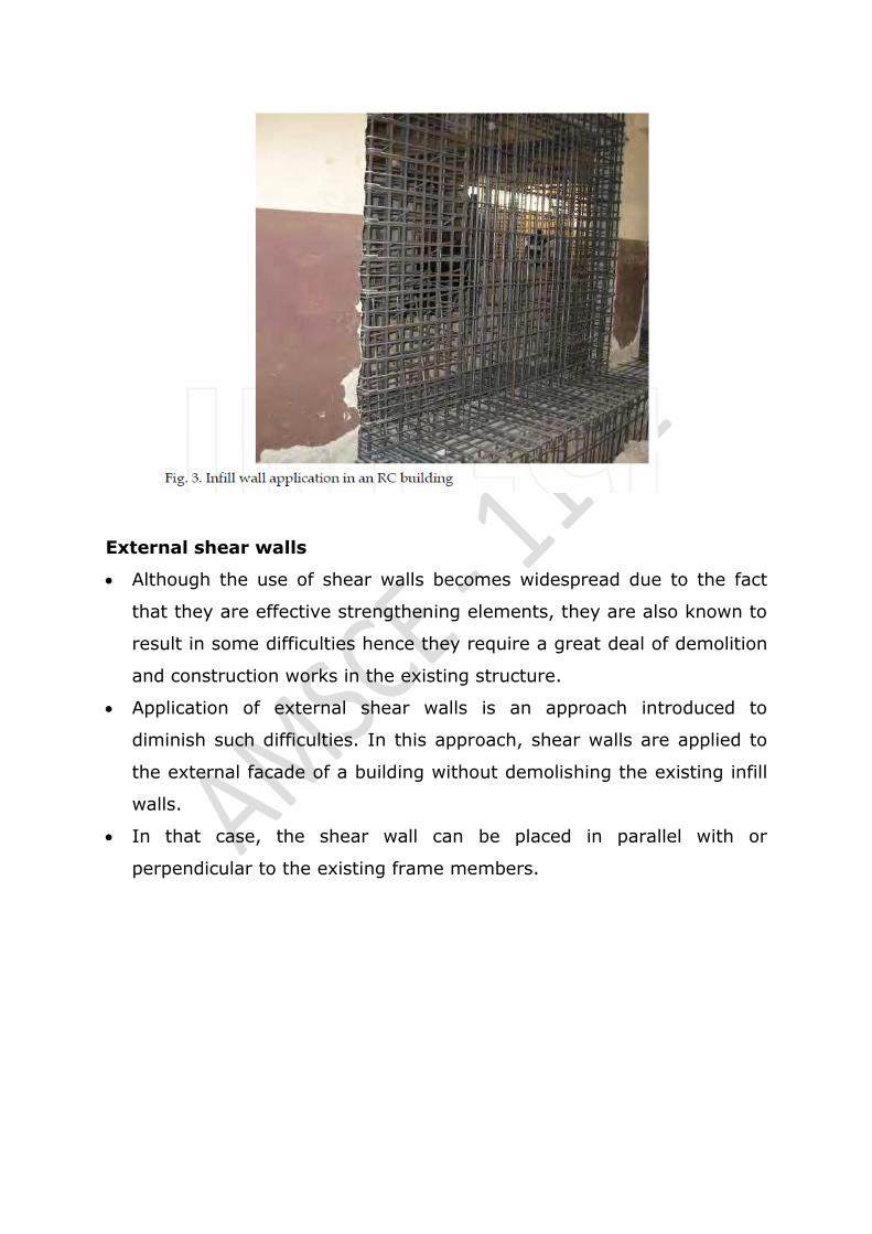
External shear walls
Although the use of shear walls becomes widespread due to the fact
that they are effective strengthening elements, they are also known to
result in some difficulties hence they require a great deal of demolition
and construction works in the existing structure.
Application of external shear walls is an approach introduced to
diminish such difficulties. In this approach, shear walls are applied to
the external facade of a building without demolishing the existing infill
walls.
In that case, the shear wall can be placed in parallel with or
perpendicular to the existing frame members.

In case the shear walls are located perpendicular to the building
façade, large openings are needed in the building facade. The shear
walls installed function like a buttress.
In cases where pile foundation is not applied for the shear wall
foundation, such shear walls are effective in only one direction.
In order to create a positive effect on earthquake resistance of the
building, they must be installed at opposite facades.
This increases the required amount of shear walls and costs. For all
these reasons, external shear walls that located perpendicular to the
external facade are not preferred in the application.

Steel bracing
Steel bracing for RC frames has also been used to reduce drift
demands. Bracing can either be implemented inside the frame or
applied from outside of the system like RC walls. Post-tensioning can
also be applied to bracing elements.

In either case, steel bracing offers more suitable solutions in
aesthetical terms for numerous applications. Although its application
inside the building is not easy for those buildings with small openings,
it particularly allows easy installation across the axes on external
facades. Research on various types of bracing styles is available in the
literature.
Architectural characteristics and functionality can be less disturbed by
using an appropriate bracing style. Figure 11 presents the use of
buttress type steel shear wall constructed on the building‟s external
facade as a different example.
Design of steel elements must be made in conformity with the details
specified in steel standards and codes. For the connection between the
existing structure and steel members, the anchor design principles
given in the subsequent section may be utilized.
Another mode of damage that must especially be considered in the
buttress type steel shear walls is to be the out-of-plane buckling of the
compression elements of the buttress type shear wall placed.
If possible, it is recommended to install lateral supports at storey
levels to prevent lateral buckling. Use of such elements may also
economize design of shear walls to a certain extent.

Infill strengthening
Another method that can be used apart from adding new ductile
shear walls to a building with an inadequate earthquake resistance
is to improve both capacities and ductility of the existing brittle
partition walls which are constructed between columns and beams
in the form of fills.
Those walls of which effects on the behavior are not considered
during structural design can generally produce a certain bracing
effect and make a positive contribution to the behavior.
There are too many uncertainties regarding the behavior of these
members and they are not likely to produce a desired bracing effect
at all times.
Partition walls may also lead to brittle damages across the
surrounding columns by exhibiting many different behaviors.
In addition, these walls are the members that are first damaged and
lose their bearing capacity in a building under earthquake loads. A
wide range of methods were developed to enhance capacity and
ductility of these walls.
6. How do you repair and rehabilitate a structure distressed due to
fire? (April/May 2018)
Surface Preparation
The original concrete cover was chipped off to expose the existing
reinforcing bars. Cleaning of the reinforcing bars proceeded
immediately using a wet type sand blasting equipment until all the
reinforcing bars were to bare white metal finish.
High pressure water spraying is used immediately before epoxy
application in order to remove all loose and defective concrete and for
final cleaning of reinforcing bars. This utilized a 6,000 psi (41.3 Mpa)

High Pressure washer. The quality of bonding surface and rough
texture was assured by this final surface preparation procedure.
The tight spaces and reinforcing bars cages required epoxy application
by hand brushing. It was therefore necessary to require that the epoxy
would have an adequately long “overlay time” of at least six (6) hours
to allow application, erection of forms and pouring of concrete. This
requirement meant that the forms would have to be collapsible and
allow for easy installation.
Prefabricated laminated plywood forms were specified to eliminate the
need to refinish the stripped surfaces.
Concreting
It was necessary to pour the concrete columns in two lifts with the last
lift being poured monolithically with the upper Beam Column joint .
Maximum 3/8” (9.5mm) aggregate was specified to ensure that the
congested areas are effectively filled by concrete.
Breather holes were punched in the slabs to prevent entrapment of air
that could block the flow of concrete. Very small diameter hand held
electric Driven Pencil Poker Vibrators were utilized in most instances
due to the tight spaces involved.
The Concrete Mix required the use of a plasticizer because of the low
water cement ratio (0.42) required on top of the minimum guide
specification of fc‟=4000 psi (27.6 Mpa) Concrete Cylinder
Compressive Strength.
The low water cement ratio was required to reduce shrinkage to a
minimum. Wet curing of the poured concrete elements also helped to
reduce shrinkage. The more than liberal distribution of new and old
reinforcing bars in a way prevented shrinkage movements that would
have otherwise caused concrete to crack.
7. Explain the methods used for fire protection in RC building.
(April/May 2019) (Nov/Dec 2017)
If the bottom side of the slab is subjected to fire, the strength of the
concrete and the reinforcing steel will decrease as the temperature
increase. However, it can take up to three hours for the heat to
penetrate through the concrete cover to the steel reinforcement.
As the strength of the steel reinforcement decreases, the moment
capacity of the slab decreases. When the moment capacity of the slab
is reduced to the magnitude of the moment caused by the applied
load, flexural collapse will occur.
It is important to point out that duration of fire until the reinforcing
steel reaches the critical strength depends on the protection to the
reinforcement provided by the concrete cover.
Fire resistance in concrete structures will vary in relation to the type
of aggregate used. Table 1 shows a summary of the minimum
thickness requirements for floor slabs and cast in place walls for
different concrete types and for different
Fire resistance ratings. Table 2 summarizes the minimum column
dimensions for different concrete type s and different fire resistance
ratings.
Another factor to be considered in complying with fire-resistive
requirements is the minimum thickness of concrete cover for the
reinforcement. The minimum concrete cover to the positive moment
reinforcement is given in Table 3 for one-way or two-way slabs with
flat undersurfaces. The minimum concrete
Cover to the positive moment reinforcement (bottom steel) in
reinforced concrete beams is shown in Table 4.


COLUMNS
The fiber reinforcing on the columns was applied transversely and
designed to increase the ultimate compressive load of the members by
confining the concrete.
The insulation completely covered the fiber reinforcing and hence the
entire surface of the column. The applied thickness of the insulation on
the round column was 15mm and the applied thickness on the square
column was 20mm.
BEAM SLAB ASSEMBLIES
The fiber reinforcing on the beams consisted of a longitudinal strip
along the bottom of the beam‟s web designed to increase the flexural
strength and a stirup on each end. The stirrup on the ends was
designed to show shear reinforcing.
Although both beams received identical fiber reinforcing, the insulation
was applied to the beams in two different configurations. This was to
address the goal of reducing the amount of required surface area that
has to be covered.
The first beam assembly consisted of the insulation being applied over
the underside of the beam as well as continuing up the web and
extending onto the underside of the flange for a small distance.
Insulation on this specimen was applied at 15mm thickness. This is the
layout that would be anticipated for beams strengthened for both
flexure and shear. The second specimen consisted of the insulation
being applied to the underside of the beam and then terminating a
short distance upto the web.
Insulation on this specimen was applied at 20mm thickness. This
layout was designed for beams strengthened with FRP to increase
flexural capacity only. The amount of the insulation system was
optimized to be the most cost effective solution.

Both beam assemblies and both columns passed the requirements of
the testing for 4 hours. They sustained the applied load without failure
and met all the internal steel temperature requirements.
In the United States and Canada, this testing meets the requirements
to provide up to a 4 hour rating and demonstrates that the FRP
strengthened section can take higher design loads during the fire
event.
8. Explain the different repair methods of various types of
cracks:(April/May 2019)
I. REPAIR OF DORMANT CRACKS:
Sealing of Cracks:
Sealing of cracks as stand alone repair should be used in
conditionswhere structural repair is not necessary. Isolated cracks
whetherextending through the concrete section or partially into it,
should be sealedat the concrete surfaces.
For this a slot of approx. 25mm wide should besaw cut upto 10mm
deep along the crack keeping crack at the center ofthe slot.
The concrete should be chiseled out from between the two sawcut
edges and concrete should be further undercut beyond the 10mmdepth
up to say 20mm depth so that the base width is slightly greater
thanthe surface width.
After the slot is thoroughly cleaned, soaked with waterfor 10 hrs. and
surface dried, a bond coat/ primer coat, of an approximatelatex
bonding compound should be applied.
Once the primer becomestacky, high strength polymer modified
cementitious mortar withspecification mentioned in Para 10.1 should
be filled in the slot, properlytamped and surface finished.

Curing compound should be applied assoon as surface becomes touch
dry. 7 days wet curing should be done bycovering with wet Hessian
and polythene sheet.
Routing and Sealing of Cracks:
Alternatively a V-groove should be prepared along the crack at the
surfaceranging in depth from 6 to 25mm and minimum opening at
surface of6mm Fig.
A concrete saw, hand tools or pneumatic tools may be used. The
grooveis then cleaned by air blasting, sand blasting or water blasting
and dried.A sealant is placed into the dry groove and allowed to cure.
The sealant may be any of several materials, including
epoxies,urethanes, silicones, polysulphides, asphaltic materials or
polymermortars.
A bond breaker may be provided at the bottom of the groove toallow
the sealant to change shape, without a concentration of stress onthe
bottom. The bond breaker may be polyethylene strip or tape which
willnot bond to the sealant.
Bond Breaking:
In some cases over bonding (strip coating) is used independently of or
inconjunction with sealing. For this an area approx. 25 to 75mm on
eachside of the crack is sand blasted or cleaned by other means, and a

coating(such as urethane) 1 to 2mm thick in a band is applied over the
crack.
Abond breaker may be used over the crack or over a crack
previouslysealed (Fig. 12). Cracks subject to minimal movement may
be overbanded, but if significant movement can take place, sealing
must be usedin conjunction with over banding to ensure a water proof
repair.
Fig. Effect of Bond Breaker
Epoxy Injection:
Cracks as narrow as 0.3mm can be bonded by the injection of
epoxysuccessfully in buildings, bridges and other concrete structures.
However,unless the cause of the cracking has been corrected, it will
probably recurnear the original crack.
If the cause of the crack cannot be removed and itis not causing
reduction in strength of the structure, then either the crackcould be
sealed with flexible sealant thus treating it as a joint or establisha
joint that will accommodate the movement and then the crack should
begrouted with epoxy.
With the exception of certain moisture tolerantepoxies, this technique
is not applicable if the cracks are actively leakingand cannot be dried
out. Epoxy injection requires a high degree of skill forsatisfactory
execution, and the ambient temperature may limit applicationof the
technique.

II. REPAIR TO ACTIVE CRACKS:
Drilling and Plugging through Crack:
One of the approximate methods would be to drill holes normal to
cracks, fillthem with a suitable epoxy or epoxy-mortar formulation and
then placereinforcement bars (of predetermined sizes and lengths) in
them to stitchacross the cracks.
The bars may be placed in the clean holes prior to fillingthe epoxy (so
as to save loss of epoxy) but then great care is needed not toentrap
any air.
Stitching:
Stitching involves drilling holes on both sides of the crack and grouting
inU-shaped metal units with short legs (staples or stitching dogs) that
spanthe crack as shown in Figure.
Stitching should be used when tensile strength has to be restored
backacross major cracks. Stitching a crack tends to stiffen the
structure andthe stiffening may increase the overall structural restrain,
causing theconcrete to crack elsewhere.
Therefore, it is necessary that properinvestigation is done and if
required, adjacent section or sections arestrengthened using

technically designed reinforcing methods. Becausestresses are often
concentrated, using this method in conjunction withother methods may
be necessary.
The procedure consists of drilling holes on both sides of the
crack,cleaning the holes and anchoring the legs of the staples in the
holes, witheither a non-shrink cement grout or any epoxy resin-based
bondingsystem.
The staples should be variable in length, orientation, or both andthey
should be located so that the tension transmitted across the crack
isnot applied to a single plane within the section but is spread over an
area.
External Prestressing:
The flexural cracks in reinforced concrete can be arrested and
evencorrected by the „Post –tensioning‟ method. It closes the cracks
byproviding compression force to compensate for tensions and adds
aresidual compression force.
This method requires anchorage of the tierods(or wires) to the
anchoring device (the guide – bracket- angles) attached to the beam
Fig.
Fig.14 Post tensioning crack beam
The rods or wires are then tensioned by tightening the end-nuts or
byturning of turnbuckles in the rods against the anchoring
devices.However, it may become necessary in certain critical case to
run at leastan approximate stress-check to guard against any possible
adverseeffects.

Drilling and Plugging:
When cracks run in reasonable straight lines and are accessible at
oneend, drilling down the length of the crack and grouting it to form a
key as shown in Fig. couldrepair them.
A hole of 50 to 75mm dia depending on width of crack should be
drilled,centered on and following the crack. The hole must be large
enough tointersect the crack along its full length and provide enough
repair materialto structurally take the loads exerted on the key.
The drilled hole shouldthen be cleaned, made tight and filled with
grout. The grout key preventstransverse movements of the sections of
concrete adjacent to the crack.The key will also reduce heavy leakage
through the crack and loss of soilfrom behind a leaking wall.
If water tightness is essential and structuralload transfer is not, the
drilled hole should be filled with a resilient materialof low modulus in
lieu of grout. If the key effect is essential, the resilientmaterial can be
placed in a second hole, the first being grouted.
Gravity Filling:

Low viscosity monomers and resins can be used to seal cracks with
widthof 0.03mm to 0.3mm by gravity filling. High molecular-
weightmethacrylates, urethanes and some low viscosity epoxies
could be usedsuccessfully.
Lower the viscosity, finer the cracks that can be filled. Firstthe
surface should be cleaned by air blasting and/ or water blasting.
Wetsurfaces should be permitted to dry several days to obtain the
best crackfilling. The monomer or resin can be poured on the
surface and spreadwith brooms or rollers
Cement Grouting:
Wide cracks, particularly in mass concrete abutments/piers and
masonrysubstructures may be repaired by filling with portland cement
grout. Thismethod is effective in sealing the crack in concrete, but it
will notstructurally bond cracked sections.
Chemical Grouting:
It consists of solutions of two or more chemicals, such as
urethanes,sodium silicates, and acrylomides that combine to form a
gel, a solidprecipitate, or foam. Cracks in concrete as narrow as
.05mm could befilled with grout.
9. Discuss the sea water attack on concrete? /Marine exposure
(April/May 2019)
Effects of Continuous Immersion of Concrete in Sea Water.
Concrete that is totally and continuously immersed in water, even ifthe
water contains dissolved salts such as are found in sea water
generallymay be regarded as being in a protected exposure.

Continuous immersionusually provides a uniformity of environment
with respect to temperatureand moisture content that prevents the
immersed concrete from being subjectedto such deteriorating
influences as frost action, volume change dueto wetting and drying,
and differential volume change due to moisture content differences
between the surface and the interior.
Continuous immersionalso tends to reduce the potential for chemical
reaction by removingchanges in degree of saturation as a mechanism
for the flow into and outof the concrete of solutions containing ions
that are capable of attacking'constituents of the concrete, and leaving
only concentration gradients asthe means of ingress of such ions.
The aggressiveness of water increases withincreasing concentration of
the relevant substances, but that aggressivenessis also increased by
higher temperatures, higher pressures, wetting and drying, or
mechanical abrasion by fast-flowing or turbulent waters.
Effects of Intermittent Immersion of Concrete in Sea Water
Most concrete structures exposed to sea water are partially or
whollysituated so that they are sometimes immersed in sea water and
sometimesexposed to the air.
If the structure is located where the temperaturesfall below freezing,
then the concrete that is exposed to the air withfalling tide is probably
subjected to as severe frost action as is any concretein natural
exposure.
The second important effect on concrete related to wetting and
dryingis the volume change relations due to changes in, or changes in
uniformityof, moisture content. Thesephenomena often referred to as
"dryingshrinkage" effects.
10. What are the different methods of demolition (or) Explain the
procedure for demolishing main structural members(Nov/Dec
2018) (April/May 2017) (Nov/Dec 2017) (April/May 2018)

There are two types of demolition
A. Non explosive demolition method
B. Explosive demolition method
A. Non explosive demolition method
Demolition of a structure done with some or other equipment
without use of any explosive. Different equipments used for the
demolition activity are
A.1 Sledge Hammers and rammers
A sledge hammer and rammers, equipment used for removing a
stone wall or a single column. It consists of a long stem with a
metallic head. It is used to give impacts on the surfaces and that
cause the demolition of structure. It cannot be used for removal
of large buildings.
A.2 Excavators and Bulldozers
Hydraulic excavators may be used to topple one-or two-story
buildings by an undermining process. The undermining process
means erode the base or foundation, i.e., dig or excavate
beneath the foundation so as to make it collapse.
The strategy of excavation is to undermine the building while
controlling the manner and direction in which it falls.
The demolition project manager will determine where under
mining is necessary so that the building is pulled into the desired
manner and direction.
Safety and cleanup considerations are also taken into account in
determining how the building is undermined and ultimately
demolished.
A.3 Wrecking Balls or Spilling Balls

In case of buildings have greater heights 5 onwards story
machineries like normal excavators and bulldozers are not
sufficient. In such cases crane with wrecking balls or spilling balls
are used to perform the demolition activity.
The wrecking balls are steel balls hanging from a steel rope
which is attached to the crane.
This method is more effective only for high rise masonry
structures because of the uncontrolled backward movement of
steel ball after the impact on the wall surface.
Nowadays this method is not commonly used because of this
uncontrolled behavior of wrecking balls which may cause some
other accident.
B. Explosive Demolition method
The basic idea of explosive demolition is quite simple, easy and fast.
If we remove the support of the structure of a building at a certain
point, the section of the building above the point will come down on
the part of the building below that point from where it is exploded.
If this upper section is heavy enough, it will collide with the lower
part with sufficient force to cause significant damage. The
explosives are just trigger for the demolition. It‟s gravity that brings
the building down.
Demolition blasters or blasting expert (“Blasting expert” means a
person who is the holder of a valid mine blasting certificate.) load
explosives on several different levels of the building so that the
building structure falls down on itself at multiple points.
When everything is planned and executed correctly, the total
damage of the explosives and falling building material is sufficient

to collapse the structure entirely, so cleanup crews are left with only
a pile of rubble.
The main challenge and risk in bringing a building down is controlling
which way it falls. There are mainly two ways to bring down a building,
1. Falling like a tree
2. Falling from crest to foot
B.1 Falling like a Tree
In this method the blasting crew to collapses the building over on
one side, into a parking lot or other open area with the help of
blast.
This sort of blast is the easiest to execute, and it is generally the
safest way to perform demolition which is something like felling a
tree.
For example to topple the building to the north, the blasters
detonate explosives on the south side of the building first , in the
same way you would chop into a tree from the south side if you
wanted it to fall in that direction .
Blasters may also secure steel cables to support columns in the
building, so that they are pulled a certain way as they crumble.
B.2 Falling from crest to foot
Many times, a building is surrounded by numbers of structures
that must be preserved. In this case, the blasters are used for true
implosion, demolishing the building so that it collapses straight
down into its own foot (that means the total area of building is
removed into the base of the building).
This requires great skill that only some handful of demolition
companies in the world attempt it.
Mainly there are two methods of dismantling:

1. Primary dismantling
2. Secondary Dismantling
1. Primary Dismantling:
(a) To break up the structure with an aim to reduce the height and
size of the elements.
(b) To break the structural elements into pieces that can be easily
handled for immediate removal from on site location.
2. Secondary Dismantling:
To reduce the size of the demolished debits for disposal, salvage of
scrap or processing elsewhere.
Primary dismantling methods:
Speitters
Non explosive cracking agent
Controlled demolition.
Thermal lancing
Crane and Ball method
Diamond sawing
Robotic machines.
Secondary dismantling methods:
Rock breaker
Jack hammers
o Pneumatic
o Electrical
o Hydraulic
o Petrol Engine
Concrete Pulveriser
Hand held clippers
Hydro demolition
Hydraulic Rock Breakers
Diamond sawing and Drilling

Diamond wire s.awing system
Silent expansive chemicals
Controlled Demolition (Implosion)
Hydraulic Bursting/splitting
Thermal lancing
Hydro demolition
Robotic demolition.
Controlled Demolition Technique
Implosion is a term coined by the internationally renowned
company “Controlled Demolition International" USA (CD!) for their
specialised method of demolition of tall structures. concrete, steel and
wood.
The CDI Technique:
Implosion Technology involves careful and detailed study of the
structure to Identify critical locations for placing explosives, to calculate
the amount. of charge required to plan the sequence of explosion etc. It
presents debris of concrete flying outside the defined area.
When combined with carefully timed explosive charges and
gravitational energy, the CDI Implosion Technology allows unbelievable
control over the failure of complex structures while maximizing
fragmentation of debris.
Basic Diamond Tools:
(a) Diamond Segment
Man made arsenal to attack concrete
Can be molded in many shops to suit base weapon.
(b) Common shapes of Diamond Tools
Circular Blade dia range from 100 mm to 300 mm or more
Core drill dia range from 10 rnm to 2000 mm

Wire String of beads to form endless Wire
Special shapes Cup grinders. Disc grinders
(c) Diamond Techniques
Flat sawing
Wall sawing
Core drilling
Wire sawing
Hand Sawing
Diamond Grinding
(d) Special Diamond Tools
Cup Grinders and discs
Diamond chain saw
Diamond crack saw
Span saw
Multiple wheel saws for grooving and grinding.
(e) Flat Sawing:
Use floor saw
Machines with circular diamond blade to cut horizontal members
like slabs, beams and flooring
(f) Wall sawing
Wall sawing uses circular Diamond blade with Hydraulic / Electric /
Pneumatic drive motor mounted on tracks ideal for cutting RCC walls.
(g) Core drilling
Core drilling uses diamond tipped Bits with Hydraulic /Electric /
Pneumatic drill motors.
Used for modelling holes or cutting long openings by stitch drilling
Wire Sawing: Ultimate Demolition Tool:

In wire sawing, a diamond beaded wire is reared around the RCC
members to be cut The wire is rotated at a high speed (10 km/hr) by a
special machine while constantly applying a pulling force. The diamond
wire penetrates and cuts through the steel and concrete.
Water is used as a lubricating coolant
Wire sawing has no limitation on the size of RCC member to
be cut.
This technique is ideal for fast primary demolition.
Hand Sawing:
Hand sawing uses a light weight hand held machine with diamond
Blade to cut RCC ill any direction. By this technique even over head
cutting is possible.
Hydraulic Splitters / Busters
Creates enormous stresses within the concrete bars producing
tensile cracking of concrete.
Dismantling Tools:
Hand operated Machines
Crane mounted Machines
Excavator mounted Machines
Special Machines
Robotic Machines.
11. What are the precaution to prevent water leakage in roofs and
sunken floors(April/May 2017)
1. Replace Missing Shingles Immediately.

2. Fix Ponding Surfaces.
3. Regularly Clean Your Gutters.
4. Inspect Flashing Around Vents, Valleys, Chimneys, Pipes, Skylights.
5. Inspect Your Attic Ceiling.
6. Remove Ice Buildup During Heavy Snows.
7. Find the Leakage Source
8. Fill Cracks
9. Regular Professional Maintenance
12.Explain pre-planning activities of demolition activity. (April/May
2019)
The different steps before the start of a demolition process are:
A. Surveying of site
B. Removal of hazardous materials from the site
C. Preparation of plan along with strategy to implement
D. Stability report from local authorities
E. Safety measures to be used.
A. Surveying of Site
1. Building surveying
2. Structural surveying
A.1 Building surveying
(a) Record Drawings
(b) Survey of Buildings
(c) Hazardous Materials on and in surrounding
A.2 Structural surveying
(a) Record Drawings
(b) Survey Items
(c) Special Structures
(d) Investigation and Testing at site

B. Removal of Hazardous Materials from site
B.1 Asbestos Containing Material if any on site
B.2 Presence of Soil Contamination Material
C. Preparation of plan and strategy
C.1 A detail plan showing:
C.2 A detail layout plan of all floors of the building to be
demolished,
C.3 A Detail plan showing the structural arrangement
C.4 A Detail plan showing the steps for the demolition
D. Detail Stability Report
E. Safety Measures
E.1 Training to workers
E.2 Maintenance of equipment from time to time
E.3 Electrical appliances Safety
E.4 Fire and fire extinguishers
E.5 Occupational Health a priority
E.6 Emergency Exit in Demolition Sites for safety
E.7 Vibration and its Effect
13. Consider a RC structure in a marine environment, discuss the
possible types of distress likely to affect the structure and suggest
suitable remedy/protection for the structure.
Suitable remedy/protection for the structures:
a) cathodic protection
b) impressed current system
a. Titanium Anode Mesh Encapsulation
b. Titanium Anode Mesh integral pile jacket system
c. Titanium Ribbon Mesh Slotted system
d. Discrete Anode system

c) sacrificial system
a. Arc sprayed aluminum zinc Indian
b. Zinc Mesh integral pile jacket system
c. Cast Zinc Anodes