unit 5 numerical controllibvolume5.xyz/industrialmanagementengineering/btech/semester5/... · dnc...
TRANSCRIPT

Unit 5 Numerical Control
Sections:
1. Fundamentals of NC Technology
2. Computer Numerical Control
3. Distributed Numerical Control
4. Applications of NC
5. NC Part Programming

Numerical Control (NC) Defined
Programmable automation in which the mechanical actions of a ‘machine
tool’ are controlled by a program containing coded alphanumeric data
that represents relative positions between a work head (e.g., cutting
tool) and a work part
MachineControl Unit
Power
ProgramInstructions
TransformationProcess

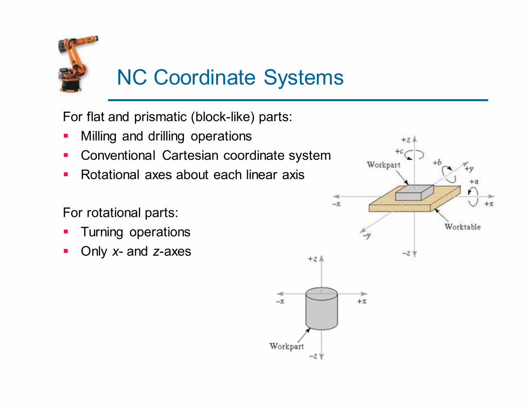
NC Coordinate Systems
For flat and prismatic (block-like) parts:
� Milling and drilling operations
� Conventional Cartesian coordinate system
� Rotational axes about each linear axis
For rotational parts:
� Turning operations
� Only x- and z-axes

Motion Control Systems
Point-to-Point systems
� Also called position systems
� System moves to a location and performs an
operation at that location (e.g., drilling)
� Also applicable in robotics
Continuous path systems
� Also called contouring systems in machining
� System performs an operation during movement (e.g., milling and turning)

Interpolation Methods
1. Linear interpolation
� Straight line between two points in
space
2. Circular interpolation
� Circular arc defined by starting point, end point, center or radius, and
direction
3. Helical interpolation
� Circular plus linear motion
4. Parabolic and cubic interpolation
� Free form curves using higher order equations

Absolute vs. Incremental Positioning
Absolute positioning
Move is: x = 40, y = 50
Incremental positioning
Move is: x = 20, y = 30.

Computer Numerical Control (CNC)
� Storage of more than one part program
� Various forms of program input
� Program editing at the machine tool
� Fixed cycles and programming subroutines
� Interpolation
� Acceleration and deceleration computations
� Communications interface
� Diagnostics

Machine Control Unit

DNC
� Direct numerical control (DNC) – control of multiple
machine tools by a single (mainframe) computer
through direct connection and in real time
� 1960s technology
� Two way communication
� Distributed numerical control (DNC) – network consisting of central computer connected to machine
tool MCUs, which are CNC
� Present technology
� Two way communication

Distributed Numerical Control
MachineControl Unit
TransformationProcess
MachineControl Unit
MachineControl Unit
CentralComputer NC Pgms
BTR BTR BTR
Computer Network
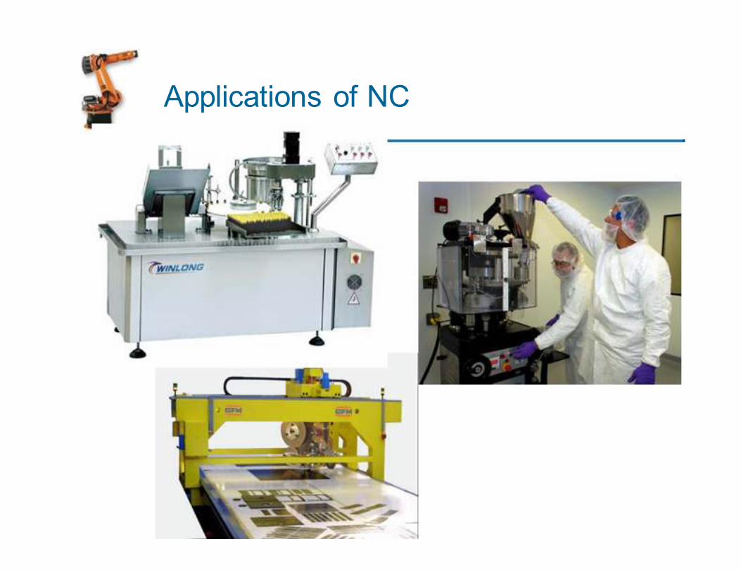
Applications of NC

NC Application Characteristics
(Machining)
� Batch and High Volume production
� Repeat and/or Repetitive orders
� Complex part geometries
� Mundane operations
� Many separate operations on one part

Cost-Benefits of NC
Costs
� High investment cost
� High maintenance effort
� Need for skilled programmers
� High utilization required
Benefits
� Cycle time reduction
� Nonproductive time reduction
� Greater accuracy and repeatability
� Lower scrap rates
� Reduced parts inventory and floor space
� Operator skill-level reduced
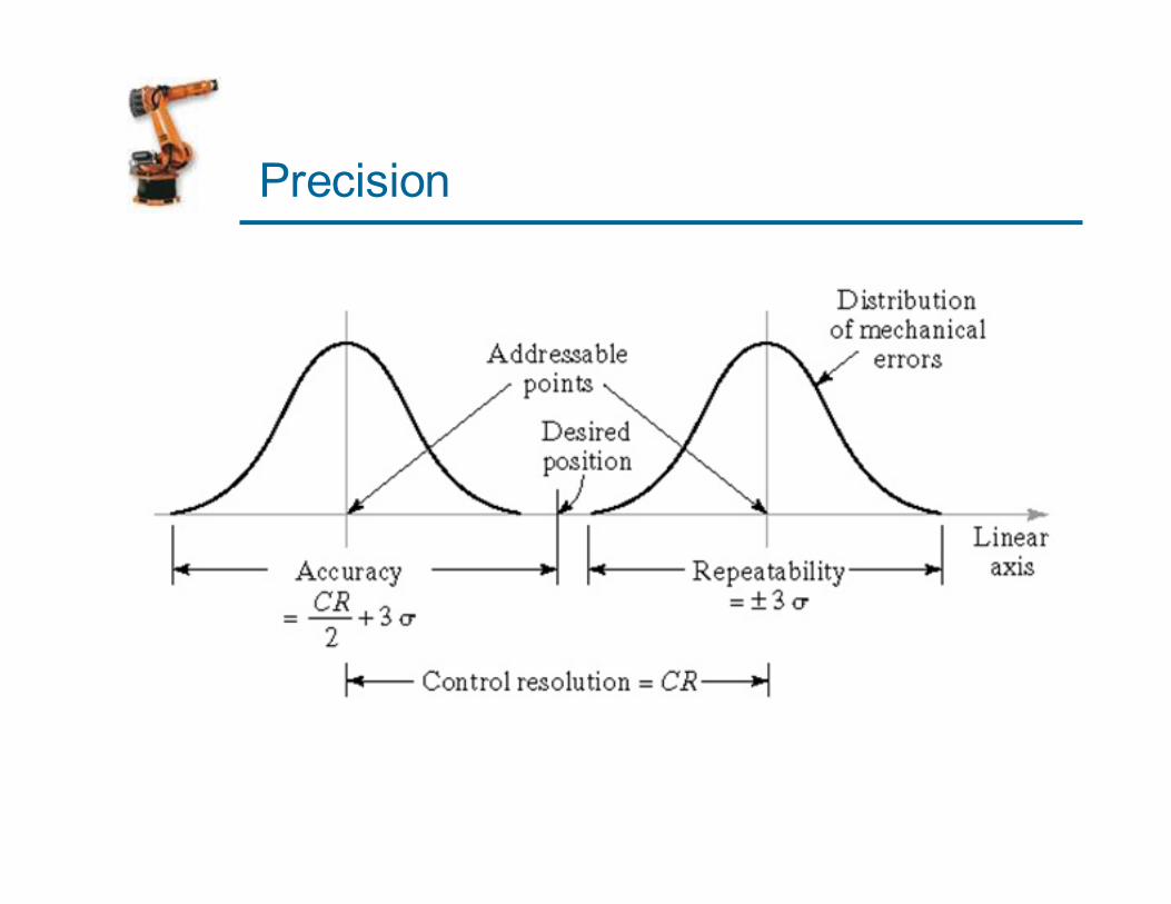
Precision

NC Part Programming
1. Manual part programming
2. Manual data input
3. Computer-assisted part programming
4. Part programming using CAD/CAM

Manual Part Programming
Binary Coded Decimal System
� Each of the ten digits in decimal system (0-9) is
coded with four-digit binary number
� The binary numbers are added to give the value
� BCD is compatible with 8 bits across tape format, the
original storage medium for NC part programs
� Eight bits can also be used for letters and symbols

Creating Instructions for NC
� Bit - 0 or 1 = absence or presence of hole in the tape
� Character - row of bits across the tape
� Word - sequence of characters (e.g., y-axis position)
� Block - collection of words to form one complete
instruction
� Part program - sequence of instructions (blocks)

Block Format
Organization of words within a block in NC part program
� Also known as tape format because the original
formats were designed for punched tape
� Word address format - used on all modern CNC
controllers
� Uses a letter prefix to identify each type of word
� Spaces to separate words within the block
� Allows any order of words in a block
� Words can be omitted if their values do not
change from the previous block
Types of Words
N - sequence number prefix
G - preparatory words
� Example: G00 = PTP rapid traverse move
X, Y, Z - prefixes for x, y, and z-axes
F - feed rate prefix
S - spindle speed
T - tool selection
M - miscellaneous command
� Example: M07 = turn cutting fluid on

Example: Word Address Format
N001 G00 X07000 Y03000 M03
N002 Y06000
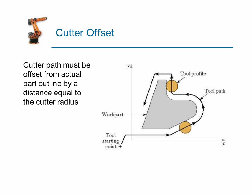
Cutter Offset
Cutter path must be
offset from actual
part outline by a
distance equal to
the cutter radius

Issues in Manual Part Programming
� Adequate for simple jobs, e.g., PTP drilling
� Linear interpolation
G01 G94 X050.0 Y086.5 Z100.0 F40 S800
� Circular interpolation
G02 G17 X088.0 Y040.0 R028.0 F30
� Cutter offset
G42 G01 X100.0 Y040.0 D05

Example
NC part program code
N001 G21 G90 G92 X-050.0 Y-050.0 Z010.0; N002 G00 Z-020.0 S1989 M03;
N003 G01 G94 G42 Y0 D05 F398; N004 G01 X075.0; N005 G01 X150.0 Y043.02; N006 G01 Y070.0; N007 G01 X080.0;
N008 G17 G02 X050.0 Y100.0 R030.0; N009 G01 Y125.0;
N010 G01 X0; N011 G01 Y0 N012 G40 G00 X-050.0 Y-050.0 Z010.0 M05;
N013 M30;
Comments
Define origin of axes. Rapid to cutter depth, turn spindle on.
Bring tool to starting y-value, start cutter offset. Mill lower horizontal edge of part. Mill angled edge at 35 degrees. Mill vertical edge at right of part. Mill horizontal edge leading to arc.
Circular interpolation around arc. Mill vertical step above arc.
Mill top part edge. Mill vertical edge at left of part. Rapid move to target point, cancel offset, spindle stop.
End of program, stop machine.
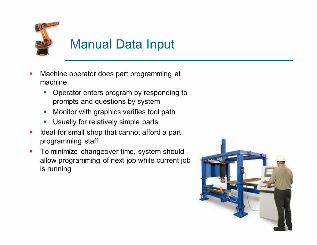
Manual Data Input
� Machine operator does part programming at machine
� Operator enters program by responding to
prompts and questions by system
� Monitor with graphics verifies tool path
� Usually for relatively simple parts
� Ideal for small shop that cannot afford a part
programming staff
� To minimize changeover time, system should
allow programming of next job while current job is running

Computer-Assisted Part Programming
� Write machine instructions using natural language
type statements
� Statements translated into machine code of the MCU
� APT (Automatically Programmed Tool) Language

Sample Statements
� Part is composed of basic geometric elements and
mathematically defined surfaces
� Examples of statements:
P4 = POINT/35,90,0
L1 = LINE/P1,P2
C1 = CIRCLE/CENTER,P8,RADIUS,30
� Tool path is sequence of points or connected line and arc segments
� Point-to-Point command: GOTO/P4
� Continuous path command: GOLFT/L1,TANTO,C1

NC Part Programming Using
CAD/CAM

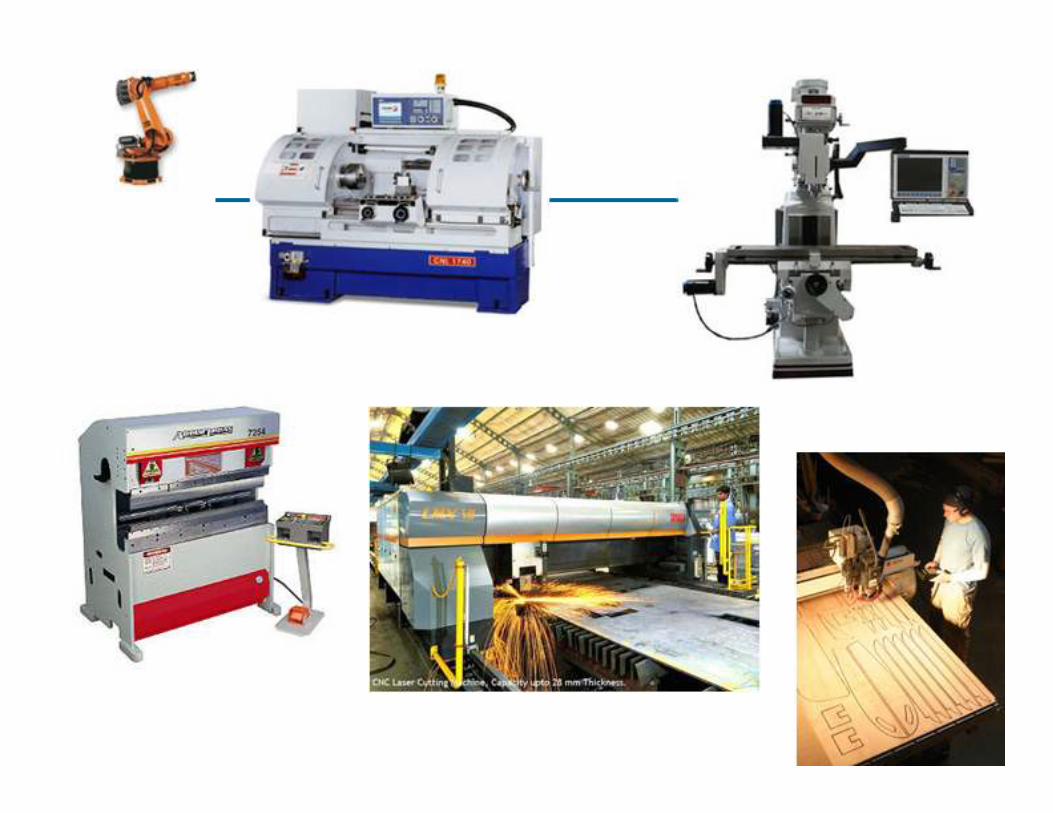
YouTube
� CNC Milling
� CNC Punching
� CNC Adhesive Bonding
� CNC Drug Insertion
� CNC Bioprocessing
� CAD/CAM
� Etc.