ch 7 numerical control - fkm.utm.myjinhoe/notes/skmp4722 modern... · system moves to a location...
TRANSCRIPT
©2008 Pearson Education, Inc., Upper Saddle River, NJ. All rights reserved. This material is protected under all copyright laws as they currently exist. No portion of this material may be reproduced, in any form or by any means, without permission in writing from the publisher. For the exclusive use of adopters of the book
Automation, Production Systems, and Computer-Integrated Manufacturing, Third Edition, by Mikell P. Groover.
Ch 7 Numerical Control
Sections:1. Fundamentals of NC Technology2. Computer Numerical Control3. DNC4. Applications of NC5. Engineering Analysis of NC Positioning Systems6. NC Part Programming

©2008 Pearson Education, Inc., Upper Saddle River, NJ. All rights reserved. This material is protected under all copyright laws as they currently exist. No portion of this material may be reproduced, in any form or by any means, without permission in writing from the publisher. For the exclusive use of adopters of the book
Automation, Production Systems, and Computer-Integrated Manufacturing, Third Edition, by Mikell P. Groover.
Numerical Control (NC) Defined
Form of programmable automation in which the mechanical actions of a machine tool or other equipment are controlled by a program containing coded alphanumeric dataThe alphanumeric data represent relative positions between a workhead (e.g., cutting tool) and a workpartWhen the current job is completed, a new program can be entered for the next job

©2008 Pearson Education, Inc., Upper Saddle River, NJ. All rights reserved. This material is protected under all copyright laws as they currently exist. No portion of this material may be reproduced, in any form or by any means, without permission in writing from the publisher. For the exclusive use of adopters of the book
Automation, Production Systems, and Computer-Integrated Manufacturing, Third Edition, by Mikell P. Groover.
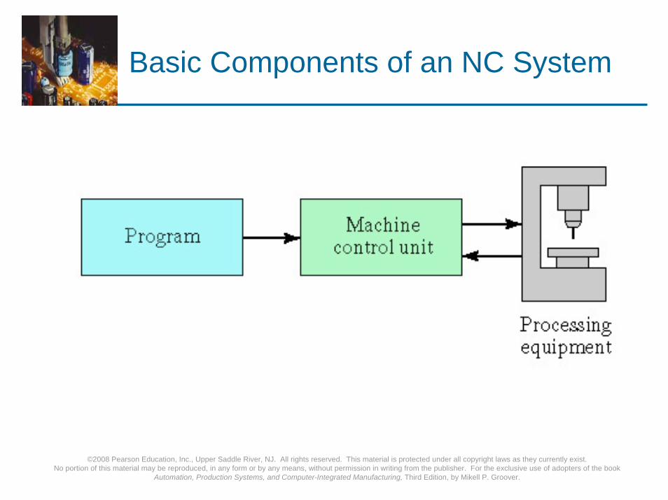
Basic Components of an NC System
1. Program of instructionsPart program in machining
2. Machine control unitControls the process
3. Processing equipmentPerforms the process
©2008 Pearson Education, Inc., Upper Saddle River, NJ. All rights reserved. This material is protected under all copyright laws as they currently exist. No portion of this material may be reproduced, in any form or by any means, without permission in writing from the publisher. For the exclusive use of adopters of the book
Automation, Production Systems, and Computer-Integrated Manufacturing, Third Edition, by Mikell P. Groover.
Basic Components of an NC System

©2008 Pearson Education, Inc., Upper Saddle River, NJ. All rights reserved. This material is protected under all copyright laws as they currently exist. No portion of this material may be reproduced, in any form or by any means, without permission in writing from the publisher. For the exclusive use of adopters of the book
Automation, Production Systems, and Computer-Integrated Manufacturing, Third Edition, by Mikell P. Groover.
NC Coordinate Systems
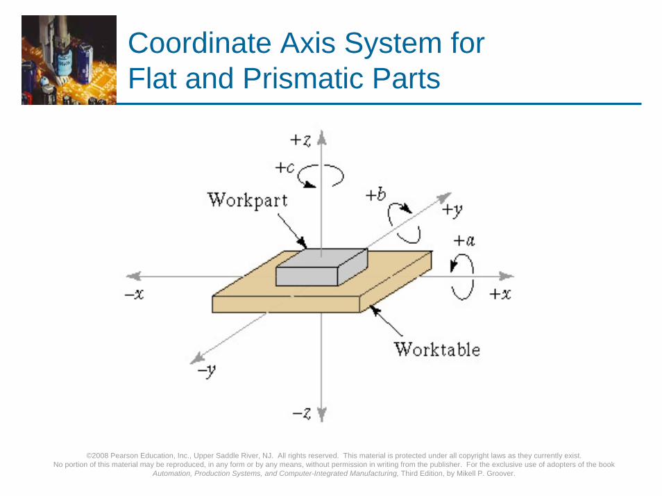
For flat and prismatic (block-like) partsMilling and drilling operationsConventional Cartesian coordinate systemRotational axes about each linear axisRight hand rule
©2008 Pearson Education, Inc., Upper Saddle River, NJ. All rights reserved. This material is protected under all copyright laws as they currently exist. No portion of this material may be reproduced, in any form or by any means, without permission in writing from the publisher. For the exclusive use of adopters of the book
Automation, Production Systems, and Computer-Integrated Manufacturing, Third Edition, by Mikell P. Groover.
Coordinate Axis System for Flat and Prismatic Parts
©2008 Pearson Education, Inc., Upper Saddle River, NJ. All rights reserved. This material is protected under all copyright laws as they currently exist. No portion of this material may be reproduced, in any form or by any means, without permission in writing from the publisher. For the exclusive use of adopters of the book
Automation, Production Systems, and Computer-Integrated Manufacturing, Third Edition, by Mikell P. Groover.
NC Coordinate Systems
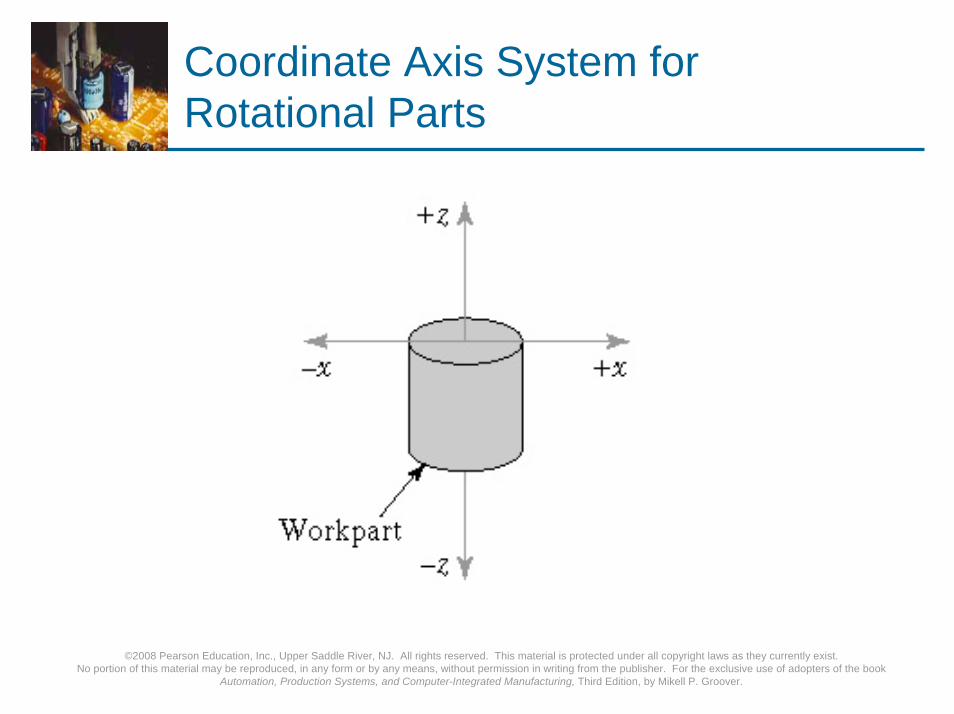
For rotational parts:Turning operationsConventional Cartesian coordinate system, but only x- and z-axesy-axis not needed in turning
©2008 Pearson Education, Inc., Upper Saddle River, NJ. All rights reserved. This material is protected under all copyright laws as they currently exist. No portion of this material may be reproduced, in any form or by any means, without permission in writing from the publisher. For the exclusive use of adopters of the book
Automation, Production Systems, and Computer-Integrated Manufacturing, Third Edition, by Mikell P. Groover.
Coordinate Axis System for Rotational Parts
©2008 Pearson Education, Inc., Upper Saddle River, NJ. All rights reserved. This material is protected under all copyright laws as they currently exist. No portion of this material may be reproduced, in any form or by any means, without permission in writing from the publisher. For the exclusive use of adopters of the book
Automation, Production Systems, and Computer-Integrated Manufacturing, Third Edition, by Mikell P. Groover.
Motion Control Systems
Point-to-Point systemsAlso called position systemsSystem moves to a location and performs an operation at that location (e.g., drilling)Also applicable in robotics
Continuous path systems Also called contouring systems in machiningSystem performs an operation during movement (e.g., milling and turning)
©2008 Pearson Education, Inc., Upper Saddle River, NJ. All rights reserved. This material is protected under all copyright laws as they currently exist. No portion of this material may be reproduced, in any form or by any means, without permission in writing from the publisher. For the exclusive use of adopters of the book
Automation, Production Systems, and Computer-Integrated Manufacturing, Third Edition, by Mikell P. Groover.
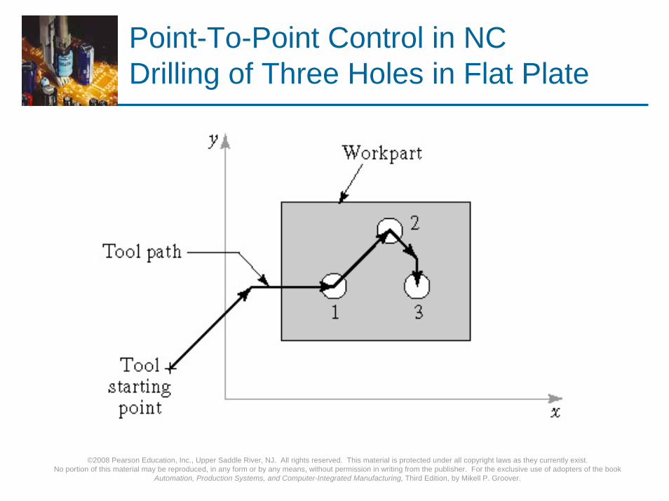
Point-To-Point Control in NCDrilling of Three Holes in Flat Plate
©2008 Pearson Education, Inc., Upper Saddle River, NJ. All rights reserved. This material is protected under all copyright laws as they currently exist. No portion of this material may be reproduced, in any form or by any means, without permission in writing from the publisher. For the exclusive use of adopters of the book
Automation, Production Systems, and Computer-Integrated Manufacturing, Third Edition, by Mikell P. Groover.
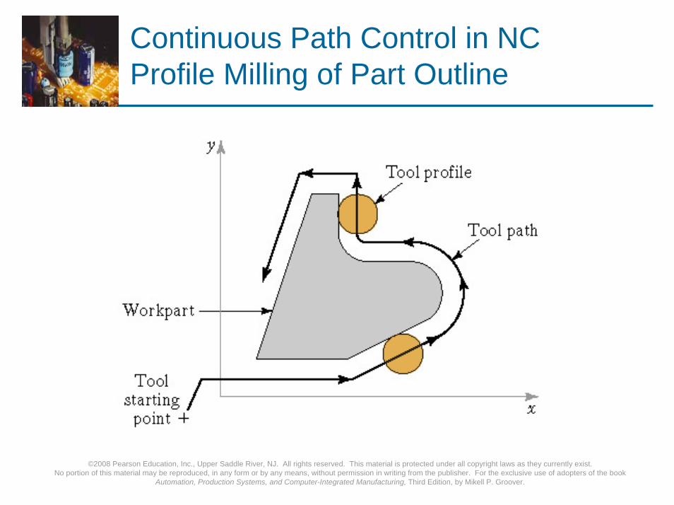
Continuous Path Control in NCProfile Milling of Part Outline

©2008 Pearson Education, Inc., Upper Saddle River, NJ. All rights reserved. This material is protected under all copyright laws as they currently exist. No portion of this material may be reproduced, in any form or by any means, without permission in writing from the publisher. For the exclusive use of adopters of the book
Automation, Production Systems, and Computer-Integrated Manufacturing, Third Edition, by Mikell P. Groover.
Interpolation Methods
1. Linear interpolationStraight line between two points in space
2. Circular interpolationCircular arc defined by starting point, end point, center or radius, and direction
3. Helical interpolationCircular plus linear motion
4. Parabolic and cubic interpolationFree form curves using higher order equations
©2008 Pearson Education, Inc., Upper Saddle River, NJ. All rights reserved. This material is protected under all copyright laws as they currently exist. No portion of this material may be reproduced, in any form or by any means, without permission in writing from the publisher. For the exclusive use of adopters of the book
Automation, Production Systems, and Computer-Integrated Manufacturing, Third Edition, by Mikell P. Groover.
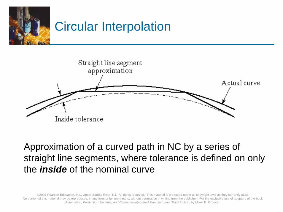
Circular Interpolation
Approximation of a curved path in NC by a series of straight line segments, where tolerance is defined on only the inside of the nominal curve
©2008 Pearson Education, Inc., Upper Saddle River, NJ. All rights reserved. This material is protected under all copyright laws as they currently exist. No portion of this material may be reproduced, in any form or by any means, without permission in writing from the publisher. For the exclusive use of adopters of the book
Automation, Production Systems, and Computer-Integrated Manufacturing, Third Edition, by Mikell P. Groover.
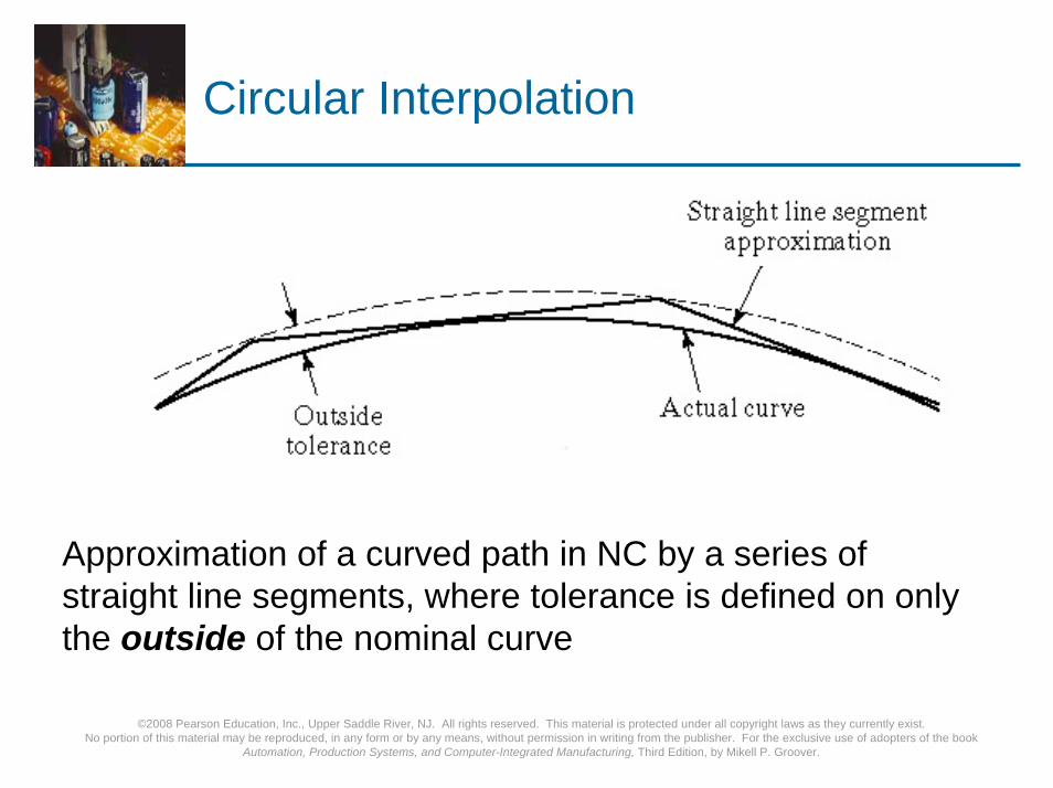
Circular Interpolation
Approximation of a curved path in NC by a series of straight line segments, where tolerance is defined on only the outside of the nominal curve

©2008 Pearson Education, Inc., Upper Saddle River, NJ. All rights reserved. This material is protected under all copyright laws as they currently exist. No portion of this material may be reproduced, in any form or by any means, without permission in writing from the publisher. For the exclusive use of adopters of the book
Automation, Production Systems, and Computer-Integrated Manufacturing, Third Edition, by Mikell P. Groover.
Circular Interpolation
Approximation of a curved path in NC by a series of straight line segments, where tolerance is defined on both the inside and outside of the nominal curve

©2008 Pearson Education, Inc., Upper Saddle River, NJ. All rights reserved. This material is protected under all copyright laws as they currently exist. No portion of this material may be reproduced, in any form or by any means, without permission in writing from the publisher. For the exclusive use of adopters of the book
Automation, Production Systems, and Computer-Integrated Manufacturing, Third Edition, by Mikell P. Groover.
Absolute and Incremental Positioning
Absolute positioningLocations defined relative to origin of axis system
Incremental positioningLocations defined relative to previous positionExample: drilling
©2008 Pearson Education, Inc., Upper Saddle River, NJ. All rights reserved. This material is protected under all copyright laws as they currently exist. No portion of this material may be reproduced, in any form or by any means, without permission in writing from the publisher. For the exclusive use of adopters of the book
Automation, Production Systems, and Computer-Integrated Manufacturing, Third Edition, by Mikell P. Groover.
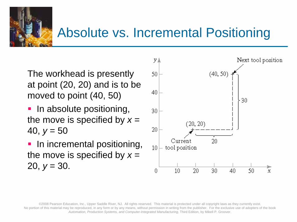
Absolute vs. Incremental Positioning
The workhead is presently at point (20, 20) and is to be moved to point (40, 50)
In absolute positioning, the move is specified by x = 40, y = 50
In incremental positioning, the move is specified by x = 20, y = 30.

©2008 Pearson Education, Inc., Upper Saddle River, NJ. All rights reserved. This material is protected under all copyright laws as they currently exist. No portion of this material may be reproduced, in any form or by any means, without permission in writing from the publisher. For the exclusive use of adopters of the book
Automation, Production Systems, and Computer-Integrated Manufacturing, Third Edition, by Mikell P. Groover.
Computer Numerical Control (CNC) –Additional Features
Storage of more than one part programVarious forms of program inputProgram editing at the machine toolFixed cycles and programming subroutinesInterpolationAcceleration and deceleration computationsCommunications interfaceDiagnostics

©2008 Pearson Education, Inc., Upper Saddle River, NJ. All rights reserved. This material is protected under all copyright laws as they currently exist. No portion of this material may be reproduced, in any form or by any means, without permission in writing from the publisher. For the exclusive use of adopters of the book
Automation, Production Systems, and Computer-Integrated Manufacturing, Third Edition, by Mikell P. Groover.
Configuration of CNC Machine Control Unit
©2008 Pearson Education, Inc., Upper Saddle River, NJ. All rights reserved. This material is protected under all copyright laws as they currently exist. No portion of this material may be reproduced, in any form or by any means, without permission in writing from the publisher. For the exclusive use of adopters of the book
Automation, Production Systems, and Computer-Integrated Manufacturing, Third Edition, by Mikell P. Groover.
DNC
Direct numerical control (DNC) – control of multiple machine tools by a single (mainframe) computer through direct connection and in real time
1960s technologyTwo way communication
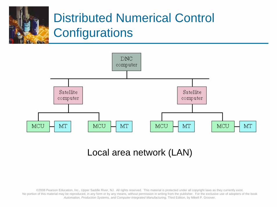
Distributed numerical control (DNC) – network consisting of central computer connected to machine tool MCUs, which are CNC
Present technologyTwo way communication

©2008 Pearson Education, Inc., Upper Saddle River, NJ. All rights reserved. This material is protected under all copyright laws as they currently exist. No portion of this material may be reproduced, in any form or by any means, without permission in writing from the publisher. For the exclusive use of adopters of the book
Automation, Production Systems, and Computer-Integrated Manufacturing, Third Edition, by Mikell P. Groover.
General Configuration of a Direct Numerical Control System
Connection to MCU is behind the tape reader (BTR). In distributed NC, entire programs are downloaded to each MCU, which is CNC rather than conventional NC

©2008 Pearson Education, Inc., Upper Saddle River, NJ. All rights reserved. This material is protected under all copyright laws as they currently exist. No portion of this material may be reproduced, in any form or by any means, without permission in writing from the publisher. For the exclusive use of adopters of the book
Automation, Production Systems, and Computer-Integrated Manufacturing, Third Edition, by Mikell P. Groover.
Distributed Numerical Control Configurations
Switching network
©2008 Pearson Education, Inc., Upper Saddle River, NJ. All rights reserved. This material is protected under all copyright laws as they currently exist. No portion of this material may be reproduced, in any form or by any means, without permission in writing from the publisher. For the exclusive use of adopters of the book
Automation, Production Systems, and Computer-Integrated Manufacturing, Third Edition, by Mikell P. Groover.
Distributed Numerical Control Configurations
Local area network (LAN)
©2008 Pearson Education, Inc., Upper Saddle River, NJ. All rights reserved. This material is protected under all copyright laws as they currently exist. No portion of this material may be reproduced, in any form or by any means, without permission in writing from the publisher. For the exclusive use of adopters of the book
Automation, Production Systems, and Computer-Integrated Manufacturing, Third Edition, by Mikell P. Groover.
Applications of NC
Machine tool applications:Milling, drilling, turning, boring, grindingMachining centers, turning centers, mill-turn centersPunch presses, thermal cutting machines, etc.
Other NC applications:Component insertion machines in electronicsDrafting machines (x-y plotters)Coordinate measuring machinesTape laying machines for polymer compositesFilament winding machines for polymer composites
©2008 Pearson Education, Inc., Upper Saddle River, NJ. All rights reserved. This material is protected under all copyright laws as they currently exist. No portion of this material may be reproduced, in any form or by any means, without permission in writing from the publisher. For the exclusive use of adopters of the book
Automation, Production Systems, and Computer-Integrated Manufacturing, Third Edition, by Mikell P. Groover.
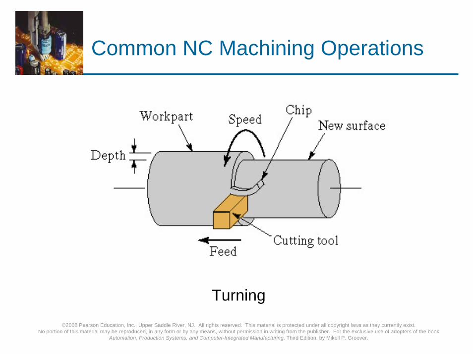
Common NC Machining Operations
Turning

©2008 Pearson Education, Inc., Upper Saddle River, NJ. All rights reserved. This material is protected under all copyright laws as they currently exist. No portion of this material may be reproduced, in any form or by any means, without permission in writing from the publisher. For the exclusive use of adopters of the book
Automation, Production Systems, and Computer-Integrated Manufacturing, Third Edition, by Mikell P. Groover.
Common NC Machining Operations
MillingDrilling

©2008 Pearson Education, Inc., Upper Saddle River, NJ. All rights reserved. This material is protected under all copyright laws as they currently exist. No portion of this material may be reproduced, in any form or by any means, without permission in writing from the publisher. For the exclusive use of adopters of the book
Automation, Production Systems, and Computer-Integrated Manufacturing, Third Edition, by Mikell P. Groover.
CNC Horizontal Milling Machine
©2008 Pearson Education, Inc., Upper Saddle River, NJ. All rights reserved. This material is protected under all copyright laws as they currently exist. No portion of this material may be reproduced, in any form or by any means, without permission in writing from the publisher. For the exclusive use of adopters of the book
Automation, Production Systems, and Computer-Integrated Manufacturing, Third Edition, by Mikell P. Groover.
NC Application Characteristics (Machining)
Where NC is most appropriate:1. Batch production2. Repeat orders3. Complex part geometries4. Much metal needs to be removed from the starting
workpart5. Many separate machining operations on the part6. The part is expensive
©2008 Pearson Education, Inc., Upper Saddle River, NJ. All rights reserved. This material is protected under all copyright laws as they currently exist. No portion of this material may be reproduced, in any form or by any means, without permission in writing from the publisher. For the exclusive use of adopters of the book
Automation, Production Systems, and Computer-Integrated Manufacturing, Third Edition, by Mikell P. Groover.
Advantages of NC
Nonproductive time is reducedGreater accuracy and repeatabilityLower scrap ratesInspection requirements are reducedMore complex part geometries are possibleEngineering changes are easier to makeSimpler fixturesShorter lead timesReduce parts inventory and less floor spaceOperator skill-level requirements are reduced

©2008 Pearson Education, Inc., Upper Saddle River, NJ. All rights reserved. This material is protected under all copyright laws as they currently exist. No portion of this material may be reproduced, in any form or by any means, without permission in writing from the publisher. For the exclusive use of adopters of the book
Automation, Production Systems, and Computer-Integrated Manufacturing, Third Edition, by Mikell P. Groover.
Disadvantages of NC
Higher investment costCNC machines are more expensive
Higher maintenance effortCNC machines are more technologically sophisticated
Part programming issuesNeed for skilled programmersTime investment for each new partRepeat orders are easy because part program is already available
Higher utilization is required
©2008 Pearson Education, Inc., Upper Saddle River, NJ. All rights reserved. This material is protected under all copyright laws as they currently exist. No portion of this material may be reproduced, in any form or by any means, without permission in writing from the publisher. For the exclusive use of adopters of the book
Automation, Production Systems, and Computer-Integrated Manufacturing, Third Edition, by Mikell P. Groover.
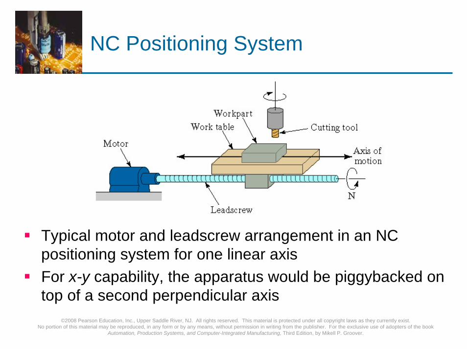
NC Positioning System
Typical motor and leadscrew arrangement in an NC positioning system for one linear axisFor x-y capability, the apparatus would be piggybacked on top of a second perpendicular axis
©2008 Pearson Education, Inc., Upper Saddle River, NJ. All rights reserved. This material is protected under all copyright laws as they currently exist. No portion of this material may be reproduced, in any form or by any means, without permission in writing from the publisher. For the exclusive use of adopters of the book
Automation, Production Systems, and Computer-Integrated Manufacturing, Third Edition, by Mikell P. Groover.
Analysis of Positioning NC Systems
Two types of NC positioning systems:1. Open-loop - no feedback to verify that the actual
position achieved is the desired position2. Closed-loop - uses feedback measurements to
confirm that the final position is the specified positionPrecision in NC positioning - three measures:1. Control resolution2. Accuracy3. Repeatability
©2008 Pearson Education, Inc., Upper Saddle River, NJ. All rights reserved. This material is protected under all copyright laws as they currently exist. No portion of this material may be reproduced, in any form or by any means, without permission in writing from the publisher. For the exclusive use of adopters of the book
Automation, Production Systems, and Computer-Integrated Manufacturing, Third Edition, by Mikell P. Groover.
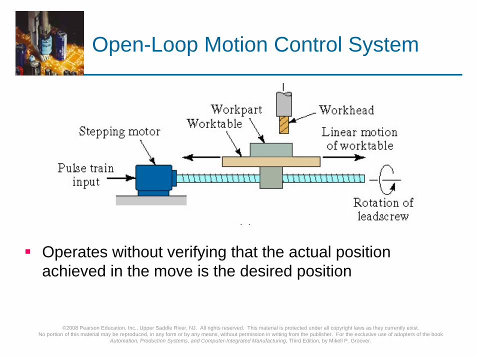
Open-Loop Motion Control System
Operates without verifying that the actual position achieved in the move is the desired position
©2008 Pearson Education, Inc., Upper Saddle River, NJ. All rights reserved. This material is protected under all copyright laws as they currently exist. No portion of this material may be reproduced, in any form or by any means, without permission in writing from the publisher. For the exclusive use of adopters of the book
Automation, Production Systems, and Computer-Integrated Manufacturing, Third Edition, by Mikell P. Groover.
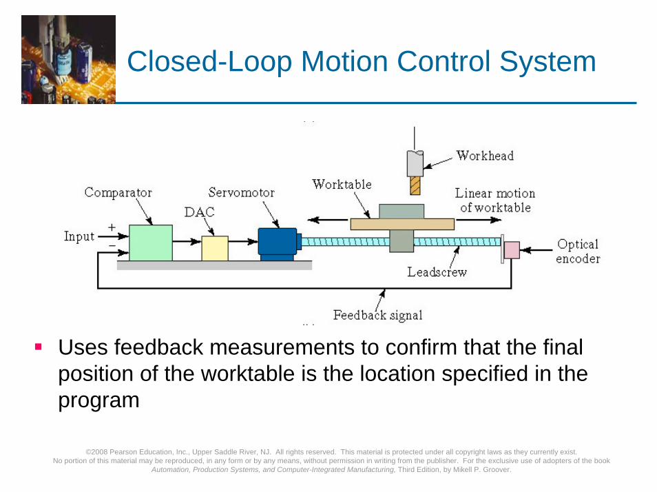
Closed-Loop Motion Control System
Uses feedback measurements to confirm that the final position of the worktable is the location specified in the program

©2008 Pearson Education, Inc., Upper Saddle River, NJ. All rights reserved. This material is protected under all copyright laws as they currently exist. No portion of this material may be reproduced, in any form or by any means, without permission in writing from the publisher. For the exclusive use of adopters of the book
Automation, Production Systems, and Computer-Integrated Manufacturing, Third Edition, by Mikell P. Groover.
Optical Encoder
Device for measuring rotational position and speedCommon feedback sensor for closed-loop NC control

©2008 Pearson Education, Inc., Upper Saddle River, NJ. All rights reserved. This material is protected under all copyright laws as they currently exist. No portion of this material may be reproduced, in any form or by any means, without permission in writing from the publisher. For the exclusive use of adopters of the book
Automation, Production Systems, and Computer-Integrated Manufacturing, Third Edition, by Mikell P. Groover.
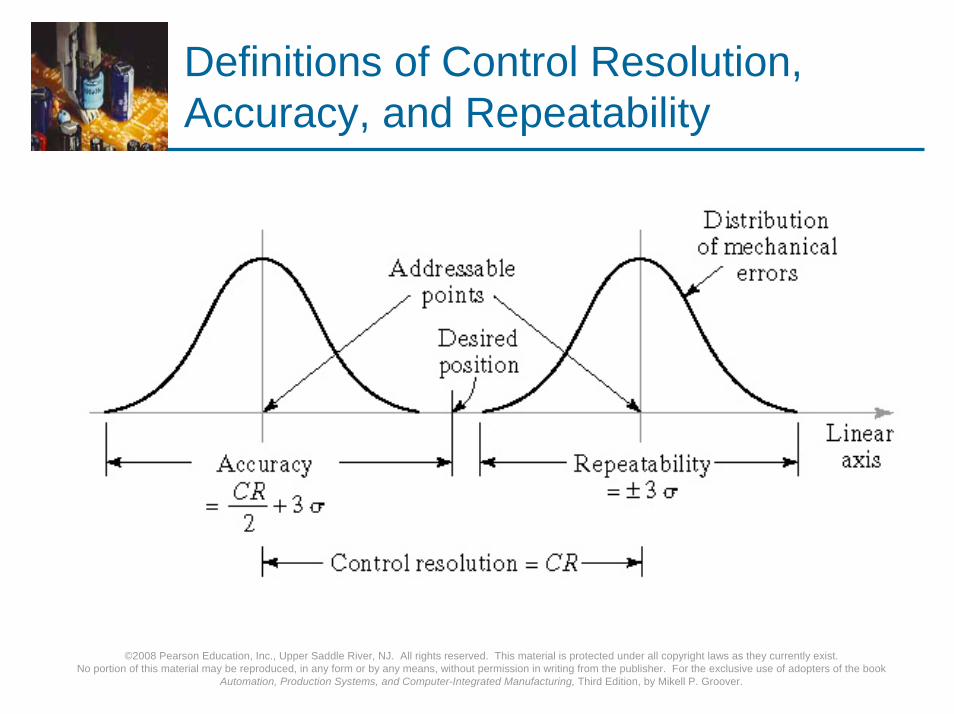
Precision in NC Positioning
Three measures of precision:1. Control resolution - distance separating two adjacent
addressable points in the axis movement2. Accuracy - maximum possible error that can occur
between the desired target point and the actual position taken by the system
3. Repeatability - defined as ±3σ of the mechanical error distribution associated with the axis
©2008 Pearson Education, Inc., Upper Saddle River, NJ. All rights reserved. This material is protected under all copyright laws as they currently exist. No portion of this material may be reproduced, in any form or by any means, without permission in writing from the publisher. For the exclusive use of adopters of the book
Automation, Production Systems, and Computer-Integrated Manufacturing, Third Edition, by Mikell P. Groover.
Definitions of Control Resolution, Accuracy, and Repeatability

©2008 Pearson Education, Inc., Upper Saddle River, NJ. All rights reserved. This material is protected under all copyright laws as they currently exist. No portion of this material may be reproduced, in any form or by any means, without permission in writing from the publisher. For the exclusive use of adopters of the book
Automation, Production Systems, and Computer-Integrated Manufacturing, Third Edition, by Mikell P. Groover.
NC Part Programming
1. Manual part programming2. Computer-assisted part programming3. Part programming using CAD/CAM4. Manual data input

©2008 Pearson Education, Inc., Upper Saddle River, NJ. All rights reserved. This material is protected under all copyright laws as they currently exist. No portion of this material may be reproduced, in any form or by any means, without permission in writing from the publisher. For the exclusive use of adopters of the book
Automation, Production Systems, and Computer-Integrated Manufacturing, Third Edition, by Mikell P. Groover.
Binary Coded Decimal System
Each of the ten digits in decimal system is coded with four-digit binary numberThe binary numbers are added to give the valueBCD is compatible with 8 bits across tape format, the original storage medium for NC part programsEight bits can also be used for letters and symbols

©2008 Pearson Education, Inc., Upper Saddle River, NJ. All rights reserved. This material is protected under all copyright laws as they currently exist. No portion of this material may be reproduced, in any form or by any means, without permission in writing from the publisher. For the exclusive use of adopters of the book
Automation, Production Systems, and Computer-Integrated Manufacturing, Third Edition, by Mikell P. Groover.
Creating Instructions for NC
Bit - 0 or 1 = absence or presence of hole in the tapeCharacter - row of bits across the tapeWord - sequence of characters (e.g., y-axis position)Block - collection of words to form one complete instructionPart program - sequence of instructions (blocks)

©2008 Pearson Education, Inc., Upper Saddle River, NJ. All rights reserved. This material is protected under all copyright laws as they currently exist. No portion of this material may be reproduced, in any form or by any means, without permission in writing from the publisher. For the exclusive use of adopters of the book
Automation, Production Systems, and Computer-Integrated Manufacturing, Third Edition, by Mikell P. Groover.
Block Format
Organization of words within a block in NC part programAlso known as tape format because the original formats were designed for punched tapeWord address format - used on all modern CNC controllers
Uses a letter prefix to identify each type of wordSpaces to separate words within the blockAllows any order of words in a blockWords can be omitted if their values do not change from the previous block

©2008 Pearson Education, Inc., Upper Saddle River, NJ. All rights reserved. This material is protected under all copyright laws as they currently exist. No portion of this material may be reproduced, in any form or by any means, without permission in writing from the publisher. For the exclusive use of adopters of the book
Automation, Production Systems, and Computer-Integrated Manufacturing, Third Edition, by Mikell P. Groover.
Types of Words
N - sequence number prefixG - preparatory words
Example: G00 = PTP rapid traverse moveX, Y, Z - prefixes for x, y, and z-axesF - feed rate prefixS - spindle speedT - tool selectionM - miscellaneous command
Example: M07 = turn cutting fluid on

©2008 Pearson Education, Inc., Upper Saddle River, NJ. All rights reserved. This material is protected under all copyright laws as they currently exist. No portion of this material may be reproduced, in any form or by any means, without permission in writing from the publisher. For the exclusive use of adopters of the book
Automation, Production Systems, and Computer-Integrated Manufacturing, Third Edition, by Mikell P. Groover.
Example: Word Address Format
N001 G00 X07000 Y03000 M03N002 Y06000
©2008 Pearson Education, Inc., Upper Saddle River, NJ. All rights reserved. This material is protected under all copyright laws as they currently exist. No portion of this material may be reproduced, in any form or by any means, without permission in writing from the publisher. For the exclusive use of adopters of the book
Automation, Production Systems, and Computer-Integrated Manufacturing, Third Edition, by Mikell P. Groover.
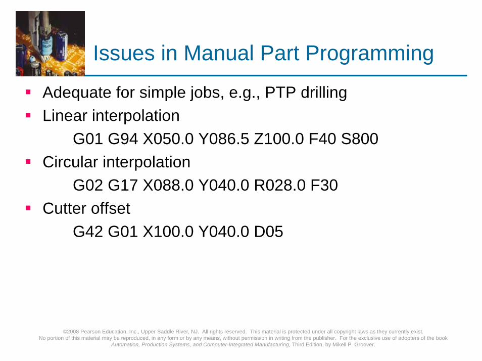
Issues in Manual Part Programming
Adequate for simple jobs, e.g., PTP drillingLinear interpolation
G01 G94 X050.0 Y086.5 Z100.0 F40 S800Circular interpolation
G02 G17 X088.0 Y040.0 R028.0 F30Cutter offset
G42 G01 X100.0 Y040.0 D05

©2008 Pearson Education, Inc., Upper Saddle River, NJ. All rights reserved. This material is protected under all copyright laws as they currently exist. No portion of this material may be reproduced, in any form or by any means, without permission in writing from the publisher. For the exclusive use of adopters of the book
Automation, Production Systems, and Computer-Integrated Manufacturing, Third Edition, by Mikell P. Groover.
Computer-Assisted Part Programming
Manual part programming is time-consuming, tedious, and subject to human errors for complex jobsMachining instructions are written in English-like statements that are translated by the computer into the low-level machine code of the MCUAPT (Automatically Programmed Tool)The various tasks in computer-assisted part programming are divided between
The human part programmerThe computer
©2008 Pearson Education, Inc., Upper Saddle River, NJ. All rights reserved. This material is protected under all copyright laws as they currently exist. No portion of this material may be reproduced, in any form or by any means, without permission in writing from the publisher. For the exclusive use of adopters of the book
Automation, Production Systems, and Computer-Integrated Manufacturing, Third Edition, by Mikell P. Groover.
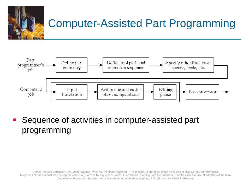
Computer-Assisted Part Programming
Sequence of activities in computer-assisted part programming
©2008 Pearson Education, Inc., Upper Saddle River, NJ. All rights reserved. This material is protected under all copyright laws as they currently exist. No portion of this material may be reproduced, in any form or by any means, without permission in writing from the publisher. For the exclusive use of adopters of the book
Automation, Production Systems, and Computer-Integrated Manufacturing, Third Edition, by Mikell P. Groover.
Part Programmer's Job
Two main tasks of the programmer:1.Define the part geometry2.Specify the tool path

©2008 Pearson Education, Inc., Upper Saddle River, NJ. All rights reserved. This material is protected under all copyright laws as they currently exist. No portion of this material may be reproduced, in any form or by any means, without permission in writing from the publisher. For the exclusive use of adopters of the book
Automation, Production Systems, and Computer-Integrated Manufacturing, Third Edition, by Mikell P. Groover.
Defining Part Geometry
Underlying assumption: no matter how complex the part geometry, it is composed of basic geometric elements and mathematically defined surfacesGeometry elements are sometimes defined only for use in specifying tool pathExamples of part geometry definitions:
P4 = POINT/35,90,0L1 = LINE/P1,P2C1 = CIRCLE/CENTER,P8,RADIUS,30

©2008 Pearson Education, Inc., Upper Saddle River, NJ. All rights reserved. This material is protected under all copyright laws as they currently exist. No portion of this material may be reproduced, in any form or by any means, without permission in writing from the publisher. For the exclusive use of adopters of the book
Automation, Production Systems, and Computer-Integrated Manufacturing, Third Edition, by Mikell P. Groover.
Specifying Tool Path and Operation Sequence
Tool path consists of a sequence of points or connected line and arc segments, using previously defined geometry elementsPoint-to-Point command:
GOTO/P0Continuous path command
GOLFT/L2,TANTO,C1
©2008 Pearson Education, Inc., Upper Saddle River, NJ. All rights reserved. This material is protected under all copyright laws as they currently exist. No portion of this material may be reproduced, in any form or by any means, without permission in writing from the publisher. For the exclusive use of adopters of the book
Automation, Production Systems, and Computer-Integrated Manufacturing, Third Edition, by Mikell P. Groover.
Other Functions in Computer-Assisted Part Programming
Specifying cutting speeds and feed ratesDesignating cutter size (for tool offset calculations)Specifying tolerances in circular interpolationNaming the programIdentifying the machine tool

©2008 Pearson Education, Inc., Upper Saddle River, NJ. All rights reserved. This material is protected under all copyright laws as they currently exist. No portion of this material may be reproduced, in any form or by any means, without permission in writing from the publisher. For the exclusive use of adopters of the book
Automation, Production Systems, and Computer-Integrated Manufacturing, Third Edition, by Mikell P. Groover.
Cutter Offset
Cutter path must be offset from actual part outline by a distance equal to the cutter radius
©2008 Pearson Education, Inc., Upper Saddle River, NJ. All rights reserved. This material is protected under all copyright laws as they currently exist. No portion of this material may be reproduced, in any form or by any means, without permission in writing from the publisher. For the exclusive use of adopters of the book
Automation, Production Systems, and Computer-Integrated Manufacturing, Third Edition, by Mikell P. Groover.
Computer Tasks in Computer-Assisted Part Programming
1. Input translation – converts the coded instructions in the part program into computer-usable form
2. Arithmetic and cutter offset computations – performs the mathematical computations to define the part surface and generate the tool path, including cutter offset compensation (CLFILE)
3. Editing – provides readable data on cutter locations and machine tool operating commands (CLDATA)
4. Postprocessing – converts CLDATA into low-level code that can be interpreted by the MCU
©2008 Pearson Education, Inc., Upper Saddle River, NJ. All rights reserved. This material is protected under all copyright laws as they currently exist. No portion of this material may be reproduced, in any form or by any means, without permission in writing from the publisher. For the exclusive use of adopters of the book
Automation, Production Systems, and Computer-Integrated Manufacturing, Third Edition, by Mikell P. Groover.
NC Part Programming Using CAD/CAM
Geometry definitionIf the CAD/CAM system was used to define the original part geometry, no need to recreate that geometry as in APT
Automatic labeling of geometry elementsIf the CAD part data are not available, geometry must be created, as in APT, but user gets immediate visual feedback about the created geometry

©2008 Pearson Education, Inc., Upper Saddle River, NJ. All rights reserved. This material is protected under all copyright laws as they currently exist. No portion of this material may be reproduced, in any form or by any means, without permission in writing from the publisher. For the exclusive use of adopters of the book
Automation, Production Systems, and Computer-Integrated Manufacturing, Third Edition, by Mikell P. Groover.
Tool Path Generation Using CAD/CAM
Basic approach: enter the commands one by one (similar to APT)
CAD/CAM system provides immediate graphical verification of the command
Automatic software modules for common machining cycles
Profile millingPocket millingDrilling bolt circles
©2008 Pearson Education, Inc., Upper Saddle River, NJ. All rights reserved. This material is protected under all copyright laws as they currently exist. No portion of this material may be reproduced, in any form or by any means, without permission in writing from the publisher. For the exclusive use of adopters of the book
Automation, Production Systems, and Computer-Integrated Manufacturing, Third Edition, by Mikell P. Groover.
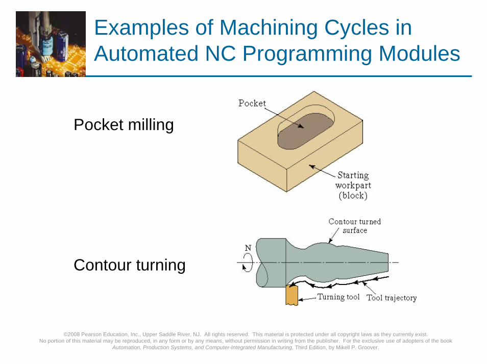
Examples of Machining Cycles in Automated NC Programming Modules
Pocket milling
Contour turning

©2008 Pearson Education, Inc., Upper Saddle River, NJ. All rights reserved. This material is protected under all copyright laws as they currently exist. No portion of this material may be reproduced, in any form or by any means, without permission in writing from the publisher. For the exclusive use of adopters of the book
Automation, Production Systems, and Computer-Integrated Manufacturing, Third Edition, by Mikell P. Groover.
Examples of Machining Cycles in Automated NC Programming Modules
Facing and shoulder facing
Threading (external)
©2008 Pearson Education, Inc., Upper Saddle River, NJ. All rights reserved. This material is protected under all copyright laws as they currently exist. No portion of this material may be reproduced, in any form or by any means, without permission in writing from the publisher. For the exclusive use of adopters of the book
Automation, Production Systems, and Computer-Integrated Manufacturing, Third Edition, by Mikell P. Groover.
Manual Data Input
Machine operator does part programming at machineOperator enters program by responding to prompts and questions by systemMonitor with graphics verifies tool pathUsually for relatively simple parts
Ideal for small shop that cannot afford a part programming staffTo minimize changeover time, system should allow programming of next job while current job is running