unit 47: engineering plant technology - free study technology/out4t3.pdf · unit 47: engineering...
TRANSCRIPT

(c) D.J.Dunn www.freestudy.co.uk 1
UNIT 47: Engineering Plant Technology
Unit code: F/601/1433 QCF level: 5 Credit value: 15
OUTCOME 4 - POWER SUPPLY EQUIPMENT
TUTORIAL 3 – TURBINES
4 Be able to analyse and report on the performance of power supply equipment
Diesel engines: specific applications of diesel engines and analysis of relevant performance
parameters e.g. compression ratio, fuel cut-off ratio, air standard efficiency for low speed and
medium/high speed diesel engines, engine trials, 2 and 4 stroke effect on output, indicated and
brake mean effective pressure, indicated and brake power, indicated and brake thermal
efficiency, mechanical efficiency, relative efficiency, specific fuel consumption
Steam turbines: measurement of power output; effect of temperature change across turbine;
impulse and reaction principles; pass out; back pressure and condensing turbines; avoidance of
wet steam; limitations on efficiency
Gas turbines: single and double shaft; regeneration and reheat; efficiency with and without
regeneration; economics of gas turbine
Alternative energy sources: wind turbines, wave energy, waste recycling, geothermal
The performance testing of steam and gas turbines are covered in national standards which can only
be studied by purchasing the relevant standards.
ASME PTC 6 for the USA. See:
http://catalog.asme.org/home.cfm?CATEGORY=CS&TAXONOMYITEMID=3104
BS EN 60953-1:1996 See:
http://www.standardsdirect.org/standards/standards2/StandardsCatalogue24_view_16233.html
This web address gives a pdf file with lots of information and pictures of steam plant and its
controls.
www.dti.gov.uk/files/file18243.pdf
You will find a wealth of information and free learning material from this web site that also
includes a free steam tables and calculator.
http://www.spiraxsarco.com/esc/

(c) D.J.Dunn www.freestudy.co.uk 2
IMPULSE and REACTION TURBINES
Turbines are generally classified as either impulse or reaction. This refers to the type of force acting
on it and causing it to rotate.
The first diagram shows a simple impulse turbine. Fluid issues
from a nozzle and hits the vanes on a wheel and makes it turn.
IMPULSIVE FORCES are exerted on an object when it diverts or
changes the flow of a fluid passing over it. A basic principle is that
the pressure of the fluid is all changed into kinetic energy by the
fixed nozzle and then the kinetic energy is converted into
mechanical work by the impulse as it is deflected by the vanes on the
rotor.
The second diagram illustrates a simple reaction turbine (Hero's
turbine). The water inside the sphere turns into steam and issues from
two nozzles. These behave like rotating rockets and drive the whole
assembly around. A basic principle is that the pressure of the fluid is
changed into kinetic energy by the rotating nozzles and it is the
reaction to the force used to accelerate the fluid through the nozzles
that causes rotation.
PRACTICAL IMPULSE DESIGN
Practical turbines have many designs
with mixes of both reaction and
impulse principles. The diagram
illustrates a practical impulse turbine
for steam and gas. The rotor has vanes
arranged around the edge. Fluid is
directed at the vanes or blades in an
axial direction by a set of nozzles.
If there is no pressure drop in the
process, the resulting force on the vane
is entirely due to the change in the momentum of the fluid and the force is entirely impulsive. It is
of interest to note that the name impulsive comes from Newton’s second law of motion that tells us
F = m v where F is the impulsive force.
The change in velocity in a tangential direction is called the velocity of whirl Δvw. If we use this,
we get the force acting in a tangential direction. F = mΔvw
Suppose the vanes to be rotating on a mean circle of diameter D at N rev/s. The linear velocity of
the vanes is u m/s. This is given by the equation u = DN
The power produced by any moving force is the product of force and velocity and this is the
theoretical power produced by the rotor known as the Diagram Power.
DIAGRAM POWER = m vw ND
The construction of the vector diagrams that would enable you to find Δvw is not covered in this
module but you will find it in tutorials on the website under the heading of thermodynamics.

(c) D.J.Dunn www.freestudy.co.uk 3
A practical impulse turbine needs several sets of
moving vanes and fixed vanes as shown. The
fixed vanes act as nozzles that convert pressure
into velocity. The steam/gas from the nozzles is
deflected by the moving row. There is a pressure
drop over each fixed row. Normally the fixed
vanes are attached to the turbine case and the
moving vanes to the rotor.
WORKED EXAMPLE No.1
The vanes on a simple steam turbine are mounted on a rotor with a mean diameter of 0.6 m. The
steam flows at a rate of 0.8 kg/s and the velocity in the whirl direction is changed by 80 m/s.
The turbine rotates at 600 rev/min. Calculate the diagram power.
SOLUTION
Rotor Speed N = 600/60 = 10 rev/s
Velocity of the vanes u = ND = x 10 x 0.6 = 18.85 m/s
Diagram Power DP = m u vw = 0.8 x 18.85 x 80 = 1206.5 W
REACTION THEORY
In a pure reaction turbine, the rotating vanes act as nozzles and the steam/gas expands as it flows
through the vanes and accelerates. The pressure of the fluid falls and the kinetic energy increases.
The force required to accelerate the steam/gas through the passage is F = m v where Δv is the change in velocity through the passages. Every force has an equal and opposite reaction so the force
that pushes the fluid through the passages has an equal and opposite reaction that propels the rotor.
In practice, pure reaction turbines are
rare and most popular designs use a
combination of impulse and reaction.
The diagram illustrates the configuration
for such a turbine. The fixed rows
accelerate the steam and there is a
pressure drop over the row. The moving
row also accelerates the steam and there
is a further pressure drop over the
moving row. The moving blades are thus
moved by both impulse and reaction
forces. If the rows of blades are
identical, the pressure drop over each is
the same and there is 50% impulse and
50% reaction.
The moving vanes experience both reaction and impulsive forces and the two together is given by
the change in momentum. The same formulae is used to calculate the diagram power.
D. P. = m vwND

(c) D.J.Dunn www.freestudy.co.uk 4
AXIAL FORCE
The change in momentum that produces the force on the
vane/blade is not only in the direction of rotation. There is
also a change of velocity and hence momentum in the
direction of the axis of rotation and this pushes the turbine
rotor in that direction. This would require a large thrust
bearing in the turbine design. This can be avoided by
placing two identical rotors back to back so the axial thrust cancels out as shown in the schematic
diagram. This is usual for steam turbine layouts.
Because the volume of the steam or gas increases greatly as it progresses along the axis, the height
of the blades increases in order to accommodate it. The picture shows a steam turbine with the
casing removed. You can see that it matches the schematic with the short vanes at the middle. The
fixed vanes are in the case.
SELF ASSESSMENT EXERCISE No.1
1. A steam turbine has its vanes on a mean diameter of 1.2 m and rotates at 1500 rev/min. The
change in the velocity of whirl is 65 m/s and the change in the axial velocity is 20 m/s. The flow rate is 1 kg/s. Calculate the following.
i. The diagram power. (6.12 kW)
ii. The axial force. (20 N)
2. A steam turbine is to be designed to rotate at 3000 rev/min and produce 5 kW of power when
1 kg/s is used. The vanes will be placed on a mean diameter of 1.4 m. Calculate the change in
the velocity of whirl that will have to be produced. (22.7 m/s)
3. A gas turbine has rotor blades on a mean diameter of 0.5 m and the rotor turns at 2000 rev/min.
The change in the whirl velocity is 220 m/s and the diagram power is 2 MW. Calculate the mass
flow rate of gas. (173.6 kg/s)

(c) D.J.Dunn www.freestudy.co.uk 5
STEAM TURBINE LAYOUTS
There are many configurations for steam turbines depending on the power and applications. On a
large power station you might see typically a High Pressure Turbine, Intermediate Pressure Turbine
and Low Pressure Turbine. Each turbine set is known as a cylinder. The H.P. and I.P. cylinders are
shown back to back to reduce axial thrust. There are two L.P. cylinders similarly laid out. The
steam is returned from the high pressure cylinder to the boiler to be re-superheated. The low
pressure cylinder will contain the steam with the largest volume so the rotor has long vanes on it. In
the L.P. cylinder, the steam will start to condense and become wet. The water droplets in the steam
would normally be very damaging and cause erosion to the vanes. The L.P. cylinder is designed
with this in mind. The schematic shows the use of feed heaters which extract steam from cylinders
to heat the feed water. This improves the efficiency.
The picture below shows the same layout with top case removed from the turbines.

(c) D.J.Dunn www.freestudy.co.uk 6
BACK-PRESSURE AND PASS-OUT TURBINES
If an industry needs sufficient quantities of process steam (e.g. for sugar refining) and electric
power, it becomes economical to use the steam for both purposes. This is done with a steam turbine
and generator and the process steam is obtained in two ways as follows.
By exhausting the steam at the required pressure (typically 2 bar) to the process instead of to
the condenser. A turbine designed to do this is called a BACK-PRESSURE TURBINE.
By bleeding steam from an intermediate stage in the expansion process. A turbine designed
to do this is called a PASS-OUT TURBINE.
The steam cycle is standard except for these modifications.
BACK-PRESSURE TURBINES
Back-pressure turbines are designed to operate with a
back pressure, unlike normal turbines that operate with
a vacuum at the exhaust. The diagram shows the basic
circuit.
WORKED EXAMPLE No. 2
A boiler supplies steam to a back pressure turbine at 50 bar and 400oC. This is expanded to a
back pressure of 3 bar where it is supplied to a process with a dryness fraction of 0.935. The
turbine drives a 60 MW electric generator. Determine the mass flow rate of the steam.
SOLUTION
Referring to the previous cycle sketch for location points we find
h2= 3196 kJ/kg h3 = hf + xhfg at 3 bar = 561 + 0.935(2164) = 2584 kJ/kg
Change in enthalpy = 2584 - 3196 = -612 kJ/kg
The power output of the turbine is found from the steady flow energy equation so
P = m(-612) kW P = -612 m kW (output)
Equate to 60 MW
60 000 = 612 m
m = 98 kg/s – the flow rate of the steam.

(c) D.J.Dunn www.freestudy.co.uk 7
PASS-OUT TURBINES
The circuit of a simple pass-out turbine plant is shown
below. Steam is extracted between stages of the turbine
for process use. The steam removed must be replaced by
make up water at point 6.
WORKED EXAMPLE No.3
A pass-out turbine plant works as follows. The boiler produces 33.7 kg/s of steam at 60 bar and
500oC and this is expanded through two stages of turbines. The first stage expands to 3 bar
where 4 kg/s of steam is removed. The second stage expands to 0.09 bar.
The condenser produces saturated water. The make up water is supplied at 1bar and 20oC. The
specific volume of the water is 0.001 m3/kg through out.
Monitoring shows that the specific enthalpy after the first stage (3 bar point) is 2678 kJ/kg and
after the second stage (0.09 bar) is 2166 kJ/kg. The specific enthalpy of the feed water entering
the boiler is 167.2 kJ/kg.
Calculate the following.
i The power output of the turbines.
ii The heat input to the boiler.
iii The power input to the feed pumps.
iv The thermal efficiency of the cycle.
v The specific steam consumption.
SOLUTION Refer to the last diagram for cycle point numbers.
h1 = 167.2 kJ/kg h2 = 3421 kJ/kg from tables h3 = 2678 kJ/kg h4 = 2166 kJ/kg.
POWER OUTPUT OF TURBINES
First Stage
Pout = 33.7(h2 – h3 ) = 33.7 (3421 - 2678) = 25039 kW
Second Stage
Pout = (29.7)(h3 - h4) = (29.7)( 2678 - 2166) = 15206 kW
Total power produced by the turbines = 40245 kW
HEAT INPUT TO BOILER
in= m(h2 - h1) = 33.7(3421 – 167.2) = 109653 kW or 109.7 MW

(c) D.J.Dunn www.freestudy.co.uk 8
POWER INPUT TO PUMPS
h1 = 167.2 kJ/kg (Given in question)
h6 = 84 kJ/kg (water at 1 bar and 20oC)
h5 = hf at 0.09 bar = 183 kJ/kg.
Volume of water = mass x 0.001
P1 = Vp = 4 x 0.001 x (60 - 1) x 105 = 23600 W or 23.6 kW
P2 = Vp = (29.7) x 0.001 x (60 - 0.09) x 105 = 177933 W or 177.9 kW
Total = 201.5 kW
The net power produced by the plant is 40245 – 201.5 = 40043 kW or 40.04 MW
EFFICIENCY Efficiency = = 40.04/109.7 = 36.5 %
SPECIFIC STEAM CONSUMPTION SCC = 40.04/33.7 = 1.188 MJ/kg
STEAM TURBINE PERFORMANCE
The previous sections have described various steam plant arrangements. These schematics do not
show the many other items of plant used such as de-aerators, de-superheaters, make up water, gland
leakages, vapour recovery and many more. Monitoring the performance of the plant is not a simple
because all these things have to be measured.
To monitor the overall plant performance, a modern system would have as much instrumentation as
required linked to a computer. The computer would be linked to data bases such as steam tables.
This would allow the enthalpy of the steam and water to be computed at all points and continuous
monitoring of power and efficiency is possible. One of the most difficult things to monitor is the
dryness fraction and flow rate of steam.
There are guidelines and standards for determining the performance of steam turbines. In the main
the quality of the steam at entry, exit and intermediate positions is measured and the enthalpy
determined to see how efficiently it is being used. The power output of the turbine would normally
be absorbed by the alternator and the electric power can be easily measured. There are many things
to be considered such as the POWER FACTOR of the electrical output.
Earlier studies told us that the theoretical power output of a turbine is the change in enthalpy ΔH. At
the simplest level, the specific enthalpy at inlet and outlet must be determined along with the mass
flow. Once the system is running steadily, the mass flow will be the flow rate of the feed water
which is easier to measure than the flow rate of the steam.
Theoretical Power = m Δh
One important parameter to be measured is the SPECIFIC STEAM CONSUMPTION. This is given
by
S.S.C. = Power Output/mass flow
In reality, the calculations are more complex because of the mass being bled for the feed heaters,
process steam and so on.

(c) D.J.Dunn www.freestudy.co.uk 9
SELF ASSESSMENT EXERCISE No.2
1. A steam cycle is performed as follows. The boiler produces 3 kg/s of superheated steam at 60
bar and 400oC. The steam is supplied to a turbine that it expands it without loss to 1.5 bar and
dryness fraction 0.882. The exhaust steam is supplied to a process. The feed water is supplied to
the pump at 1.013 bar and 100oC and delivered to the boiler at 60 bar. The pump may be
considered as ideal.
Calculate the following.
i. The power output of the turbine. (2.2 MW)
ii. The heat input to the boiler. (8.3 MW)
iii. The power input to the pump. (17.7 kW)
iv. The thermal efficiency of the cycle. (26.3%)
2. A back pressure steam cycle works as follows. The boiler produces 8 kg/s of steam at 40 bar
and 500oC. This is expanded without loss to 2 bar and dryness fraction 0.993. The pump is
supplied with feed water at 0.5 bar and 30oC and delivers it to the boiler at 31oC and 40 bar.
Calculate the following.
i. The net power output. (6 MW)
ii. The heat input to the boiler. (26.5 MW)
iii. The thermal efficiency of the cycle. (22.5%)

(c) D.J.Dunn www.freestudy.co.uk 10
GAS TURBINE ENGINES
In this section we will examine the basic
layout of common gas turbine engine
sets. The simplest gas turbine draws in
air from the atmosphere with a
continuous flow compressor. This is
usually an axial stage followed by a
centrifugal stage to turn the flow through
90o to the combustion chamber. The fuel
is injected into the hot air and ignited.
This requires an electric ignition system
as the air is not hot enough for
spontaneous ignition until the
combustion is up to working
temperature. The hot air then expands
into the turbine. The shaft of the turbine
powers the compressor and the load
attached to the output. The exhaust
passes out to atmosphere.
Studying the thermodynamics of the ideal cycle shows that the theoretical efficiency is given by the
following formulae.
)T-(T
)T-(T1
Φ
Pη
23
14
in
nettth and 0.286-
pth r1η rp is the pressure compression ratio.
This is called the Joule Cycle Efficiency and is based on the properties of air throughout the cycle.
The efficiency of gas turbine engines increases with pressure compression ratio. In practice this is
limited, as the type of compressor needed to produce very large flows of air cannot do so at high
pressures. 6 bar is a typical pressure for the combustion chamber. Also in reality the gas after the
combustion chamber is not air but a mixture of air and combustion products so this formula is only
a guide to performance.
WORKED EXAMPLE No. 4
A gas turbine uses a pressure ratio is 6/1. The air is heated from 200oC to 950oC in the
combustion chamber. The flow rate of air is 0.2 kg/s. Assuming a specific heat of 1.005 kJ/kg
K, calculate the following.
i. The ideal thermal efficiency.
ii. The heat transfer into the combustion chamber.
iii. The net power output to the load.
SOLUTION
kW 60.3 150.8 x 0.4P
Φ
Pη
kW 150.8472.4)-(1223 x 1.005 x 0.2)T-(TmcΦ
40%or 0.461r1η
nett
in
nettth
23pin
0.286-0.286-pth

(c) D.J.Dunn www.freestudy.co.uk 11
SELF ASSESSMENT EXERCISE No. 3
The specific heat capacity is 1.005 kJ/kg K throughout.
1. A simple gas turbine draws in air at 1 bar and compresses it to 7 bar. The air is heated from 185
oC to 700oC in the combustion chamber. The flow rate of air is 0.4 kg/s. Calculate the
following.
i. The ideal thermal efficiency. (42.7 %)
ii. The heat transfer into the heater. (206.7 kW)
iii. The net power output. (88.26 kW)
2. A simple gas turbine draws in 3 kg/s of air from atmosphere at 1 bar and compresses it to
10 bar. The air is heated from 293 oC to 920oC in the combustion chamber. Calculate the
following.
i. The ideal thermal efficiency. (48.2 %)
ii. The net power output. (911 Kw)
3. A simple gas turbine draws in 7 kg/s of air from atmosphere at 1 bar and compresses it to 9 bar.
The air is heated from 267 oC to 850oC in the combustion chamber. Calculate the following.
i. The ideal thermal efficiency. (46.7 %)
ii. The net power output. (1.916 MW)
FREE TURBINES
Most designs used for gas turbine sets use two turbines, one to drive the compressor and a free
turbine. The free turbine drives the load and it is not connected directly to the compressor. It may
also run at a different speed to the compressor. The diagram shows the layouts for parallel and
series turbines.

(c) D.J.Dunn www.freestudy.co.uk 12
INTERCOOLING AND REHEATING
The power output and thermal
efficiency of a gas turbine are
improved by the use of reheaters and
coolers. The air is compressed in
stages and cooled between each
stage. This reduces the power input
to the compressor. The reverse also
applies. If several stages of turbine
expansions are used and the gas
reheated between stages, the power
output and efficiency is increased.
The diagram shows this configuration.
EXHAUST GAS HEAT EXCHANGER
The exhaust gas from a turbine is hotter than
the air leaving the compressor. If heat is
passed to the air from the exhaust gas, then
less fuel is needed in the combustion chamber
to raise the air to the operating temperature.
This requires an exhaust heat exchanger. The
layout is shown in the diagram.
In order to solve problems associated with this cycle, it is necessary to determine the temperature
prior to the combustion chamber (T3).
A perfect heat exchanger would heat up the air so that T3 is the same as T5. It would also cool
down the exhaust gas so that T6 becomes T2. In reality this is not possible so the concept of
THERMAL RATIO is used. This is defined as the ratio of the enthalpy given to the air to the
maximum possible enthalpy lost by the exhaust gas. cpa is the specific heat capacity of air and cpg
is the specific heat capacity of the exhaust gas. ma is the mass of the air and mg is the mass of the
exhaust gas.
The enthalpy lost by the exhaust gas is H = mgcpg(T5 - T6)
This would be a maximum if the gas is cooled down such that T6 = T2. Of course in reality this
does not occur and the maximum is not achieved and the gas turbine does not perform as well as
predicted by this idealisation.
H (maximum) = mgcpg(T5-T2)
The enthalpy gained by the air is H (air) = macpa(T3-T2)
Hence the thermal ratio is )T(Tcm
)T(TcmT.R.
25pgg
23paa
Since the mass of fuel added in the combustion chamber is small compared to the air flow we often
neglect the difference in mass and the equation becomes
)T(Tc
)T(TcT.R.
25pg
23pa

(c) D.J.Dunn www.freestudy.co.uk 13
WORKED EXAMPLE No. 5
A gas turbine draws in air from atmosphere and compresses it with a pressure ratio of 7.5. The
air passes through an exhaust gas heat exchanger before reaching the combustion chamber. The
temperatures at various points in the cycle are given on the diagram. The specific heat capacity
cp for air is 1.005 kJ/kg K and for the exhaust gas is 1.15 kJ/kg K. Assume no losses and a
constant mass flow rate of 1kg/s.
Calculate the ideal efficiency given that the exhaust heat exchanger has a thermal ratio of 0.8.
Compare this to the efficiency when no heat exchanger is used.
SOLUTION
Referring to the numbers used on the diagram the solution is as follows.
T2 = 231oC T5 = 681
oC
Solution with heat exchanger
Use the thermal ratio to find T3.
231T414 4501.15
231T1.0050.8
2316811.15
231T1.0050.8
)T(Tc
)T(TcT.R. 3
33
25pg
23pa
T3 = 645 oC
In order find the thermal efficiency, it is best to solve the power of the compressor and turbine.
COMPRESSOR P(in)= mCpa(T2-T1) = 1 x 1.005 (231- 10) = 222 Kw
TURBINE
P(out) = mCpg(T4-T5) = 1 x 1.15 (1300 - 681) = 712 kW
P(net) = P(out) - P(in) = 490 kW (to the load)
COMBUSTION CHAMBER
(in)combustion chamber) = mCpg(T4-T3)
(in)= 1.15(1300 - 645) = 753 kW
th = P(net)/(in) = 490/753 = 0.65 or 65%
Without the heat exchanger the efficiency is th = 1 – rp-0.286 = 1-7.5
-0.286 = 0.438 or 43.8%

(c) D.J.Dunn www.freestudy.co.uk 14
SELF ASSESSMENT EXERCISE No. 4
1. A gas turbine uses a pressure ratio of 7/1. The compressor draws in 0.7 kg/s of air at 10oC and
after compression the temperature is 220 oC. The temperature after heating in the combustion
chamber is 1000 oC and after expanding through nthe turbine it is 457 oC. The specific heat
capacity cp is 1.005 kJ/kg K for air and gas. Assume no losses from the compressor or turbine.
Calculate the net power output and the thermal efficiency when an exhaust heat exchanger with
a thermal ratio of 0.8 is used. (Answers 234 kW and 56%)
2. A gas turbine draws in air from the atmosphere at 1.02 bar and 27oC. The air is compressed to
6.4 bar and 234oC. The air entering the turbine is at 1227
oC and this expands to 1.02 bar and
615oC. Assume the specific heat cp is 1.005 kJ/kg K for both the turbine and compressor. Ignore
the addition of mass in the burner. Calculate the following.
i. The air standard efficiency. (40.8%)
ii. The efficiency when an exhaust heat exchanger with a thermal ratio of 0.75 is
added. (70.7%)
Note that in reality friction in the compressor and turbine result in higher temperatures at exit and
this reduces the efficiency so figures like that in the last problem are not obtained in practice. The
solution to the next problem is just the same as before but more realistic temperatures are given.
SELF ASSESSMENT EXERCISE No. 5
1. A gas turbine uses a pressure ratio of 6.5/1. The compressor draws in 1 kg/s of air at 15oC and
after compression the temperature is 254 o
C. The temperature after heating in the combustion
chamber is 1200 oC and after expansion through the turbine the temperature is 732 o
C. The
specific heat capacity cp for air is 1.005 kJ/kg K and for the exhaust gas is 1.15 kJ/kg K.
i. The ideal efficiency without a heat exchanger. (41.4%)
ii. The ideal efficiency when an exhaust heat exchanger with a thermal ratio of 0.75 is
added. (48.3%)

(c) D.J.Dunn www.freestudy.co.uk 15
WASTE HEAT RECOVERY
When large amounts of hot exhaust gas are produced by either gas turbines or large diesel engines,
the heat in the exhaust gas may be recovered for useful applications such as using it to produce hot
water or steam in a boiler. A factory might well use a gas turbine to produce electric power and hot
water or steam. This is more economical than buying electricity. Similar schemes may be used with
any source of hot gas such as burning waste rubbish and hydrocarbon gases produced by landfill
sites or bio-digesters. Bio fuels are increasingly being used as a renewable source of fuel but this
has problems in a world hungry for food and the conflicts of wild life conservation.
Waste Heat Recovery System
SELF ASSESSMENT EXERCISE No. 6
A factory is to be built that uses both electricity and steam. There are two proposals to be
considered.
PROPOSAL 1 Produce steam in an oil fired boiler and purchase electricity.
PROPOSAL 2 Generate electric power with a gas turbine and produce steam in a waste heat
boiler using the exhaust gas.
OPERATING DATA FOR STEAM BOILER
Mass Flow rate 1 kg/s
Steam condition 5 bar and dry saturated.
Feed water temperature 15oC.
When burning fuel, the combustion efficiency is typically 85%
When using exhaust gas, the heat transfer from the gas may be assumed to be equal to the heat
gained by the water and steam. The exhaust gas is cooled to 100oC before leaving the boiler.
GAS TURBINE DATA
Pressure ratio 7
Inlet air temperature 15oC
Combustion chamber temperature 229 oC at inlet and 1500
oC at outlet
Exhaust Temperature 743 oC

(c) D.J.Dunn www.freestudy.co.uk 16
FUEL DATA
Any fuel to be burned in either the gas turbine or the boiler will be light oil with a calorific
value of 42 MJ/kg.
The cost of fuel is 12.7 pence per kg.
Electricity cost 2.5 pence per kWhr (1 kWhr = 3600 kJ)
PROPERTIES
AIR BURNED GAS
cp=1.005 kJ/kg K cp =1.1 kJ/kg K
Produce a report comparing the costs for both schemes. You will need to do the following tasks.
GUIDANCE
STEAM BOILER
Determine the following.
i. The energy required to make the steam.
ii. The fuel required in kg/s.
iii. The mass of exhaust gas required to produce the same steam in kg/s.
GAS TURBINE
You will need to equate the heat transfer from burning fuel to the energy required to raise the
temperature in the combustion chamber.
Determine the following.
vi. The mass flow of air.
v. The fuel burned in kg/s.
vi. The Power input of the compressor.
vii. The power output of the turbine.
viii. The net power for generating electricity.
COSTING
Base the cost of option 1 on the cost of fuel plus the cost of buying the same electricity as for
option 2.
Base the cost on the cost of fuel only.
What other factors would you consider when making a decision on which option take?

(c) D.J.Dunn www.freestudy.co.uk 17
ALTERNATIVE ENERGY SOURCES
Fossil fuel has become expensive and controversial as new supplies become more difficult to
extract and carbon dioxide is increasingly blamed for global warming. The search for greater
economy of fuel usage and for alternate renewable energy sources has become paramount and the
following discusses some aspects of this.
Hydro-electricity is a well used and most efficient energy sources. Hydro electric schemes produce
vast amounts of electricity very economically. The main problem is that the most readily accessible
sources of hydro-electric power are in areas of the planet where few people live (i.e. the mountains)
and distributing the electric power to the populated areas is uneconomical. For example Norway has
more than enough hydro-electricity for all its energy needs but it is easier for them to export oil and
gas than electricity. The flooding of valleys and damming of rivers is controversial but effective.
Geo-thermal energy is readily available as a source of heat but again the main sources are in remote
areas. Various ways are used to obtain steam from deep under the Earth’s crust to run steam power
plant. These are in volcanic regions where the hot rock is close to the surface. For example
countries like Iceland could generate enough geo-thermal electric power to supply much of Europe
but it is too remote to send electric power over long distances. Note that if anyone invented a
superconductor that could be used at normal temperatures - the problem would be solved.
Another factor is that leading industrial nations would like to be independent of foreign energy
sources for security reason.
Wind Turbines like other alternative sources of renewable energy
have their critics and attract the attention of objectors of one kind or
another. One of the most controversial is the use of wind farms both
on shore and off shore. Whilst the energy is free to extract with wind
turbines, the wind does not blow constantly and is not reliable. The
cost of manufacture, erection, maintenance and connection to the
electricity supply network, when compared to the value of the energy
produced, is not presently cost effective without subsidies.
(c) D.J.Dunn www.freestudy.co.uk 18
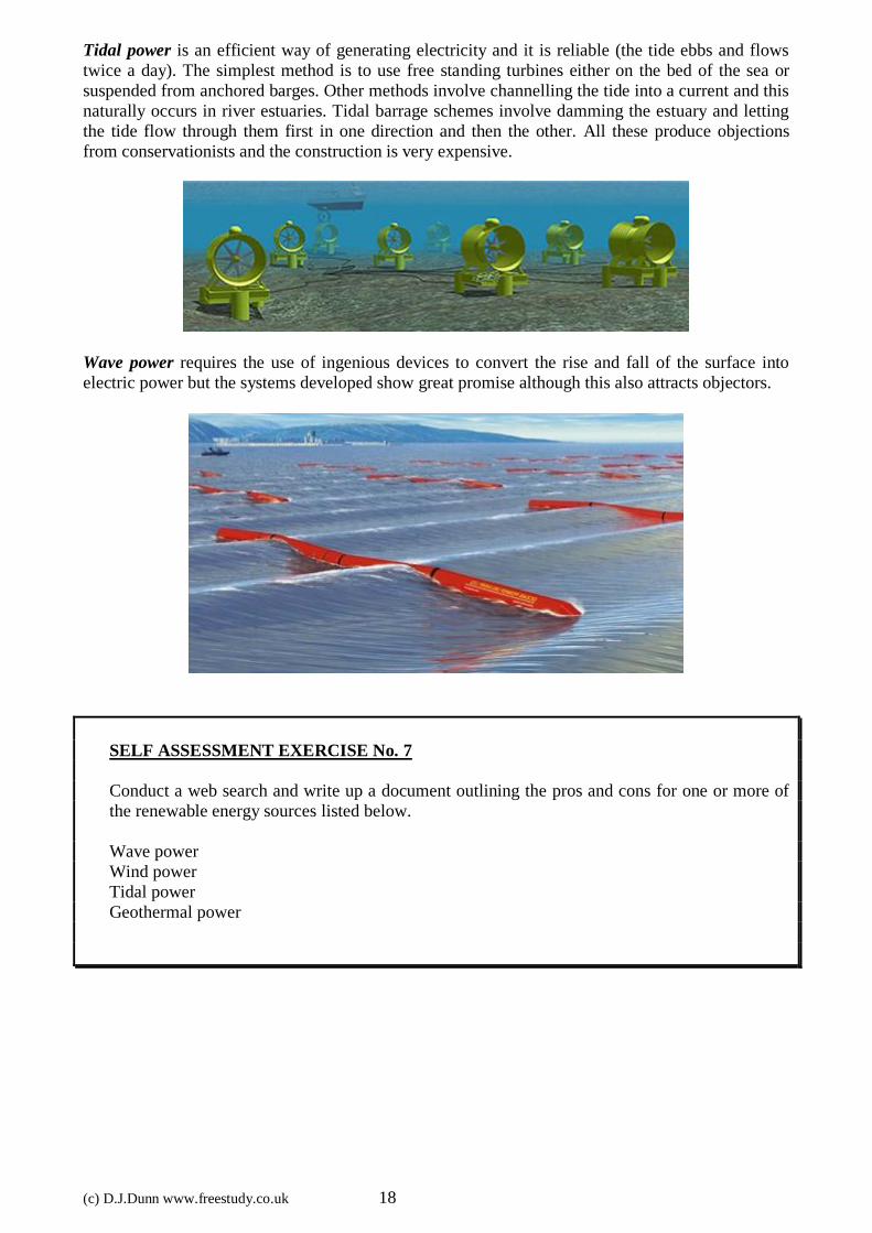
Tidal power is an efficient way of generating electricity and it is reliable (the tide ebbs and flows
twice a day). The simplest method is to use free standing turbines either on the bed of the sea or
suspended from anchored barges. Other methods involve channelling the tide into a current and this
naturally occurs in river estuaries. Tidal barrage schemes involve damming the estuary and letting
the tide flow through them first in one direction and then the other. All these produce objections
from conservationists and the construction is very expensive.
Wave power requires the use of ingenious devices to convert the rise and fall of the surface into
electric power but the systems developed show great promise although this also attracts objectors.
SELF ASSESSMENT EXERCISE No. 7
Conduct a web search and write up a document outlining the pros and cons for one or more of
the renewable energy sources listed below.
Wave power
Wind power
Tidal power
Geothermal power