unit 1(part-2)sensors and transducer
TRANSCRIPT

UNIT -1
• Sensors & TRANSDUCER
By
V.D.TAMILARASANResearch associate cum Assistant Professor
Mechanical Engineering DepartmentBannari Amman Institute of Technology

DEFINITION
• SENSOR1. It is defined as an element
which produces signalrelating to the quantitybeing measured
2. sensor can be defined as“A device which providesa usable output in responseto a specified measured.”
• TRANSDUCER1. It is defined as an element
when subjected to somephysical changeexperiences a relatedchange or an elementwhich converts a specifiedmeasured into a usableoutput by using atransduction principle.
2. It can also be defined as adevice that converts asignal from one form ofenergy to another form.

TYPE OF SENSORS AND ITS APPLICATIONS
• IN MECHATRONICS SYSTEM WE NEED TO MEASURE THE FOLLOWING PHYSICAL QUANTITIES
– SENSORS AND TRANSDUCERS ARE THE KEY ELEMENT USED FOR THE MEASUREMENT OF THE PHYSICAL QUANTITIES
– DISPLACEMENT
– TEMPERATURE
– PRESSURE
– STRESS
– POSITION AND
PROXIMITY
– VELOCITY
– MOTION
– FORCE
– LIQUID FLOW
– LIQUID LEVEL
– LIGHT SENSORS

• SENSORS– ELEMENT IN A MEASUREMENT SYSTEM THAT ACQUIRES A PHYSICAL
PARAMETER AND CHANGES INTO A SIGNAL(ALSO CAN BE DEFINED AS PART OF A TRANSDUCER WHICH SENSES OR RESPOND TO A PHYSICAL QUANTITY OR MEASURAND
SENSOR NORMALLY SENSES THE FOLLOWING PHYSICAL QUANTITIES
- POSITION- FORCES- DISTANCE- STRAIN- VIBRATION- TEMPERATURE- ACCELERATION ETC.
EXAMPLE OF SENSOR– A THERMOCOUPLE SENSES THE CHANGE IN TEMPERATURE

• TRANSDUCER– CONVERTS ENERGY FROM ONE FORM TO ANOTHER
TEMPERATURE, STRAIN --------- ELECTRICAL ENERGY
EXAMPLE- ACCELEROMETER GIVES OUTPUT VOLTAGE PROPORTIONAL TO THE MECHANICAL MOTION OF THE OBJECT

Active transducers generate electric current or voltagedirectly in response to environmental stimulation (Active
transducers are those which do not require any power source for theiroperation. They work on the energy conversion principle. They produce anelectrical signal proportional to the input (physical quantity). For example, a
thermocouple is an active transducer.)
Passive transducers produce a change in some passiveelectrical quantity, such as capacitance, resistance, orinductance, as a result of stimulation. These usuallyrequire additional electrical energy forexcitation.(Transducers which require an external power sourcefor their operation is called as a passive transducer. Theyproduce an output signal in the form of some variation inresistance, capacitance or any other electrical parameter, whichthan has to be converted to an equivalent current or voltagesignal.)

EXAMPLE OF ACTIVE TRANSDUCER

EXAMPLE OF PASSIVE TRANSDUCER

PERFORMANCE TERMINOLOGY
• 1. RANGE
• 2. SPAN
• 3. ERROR
• 4. ACCURACY
• 5. PRECISION
• 6. SENSITIVITY
• 7. HYSTERISIS
• 8. REPEATABILITY
• 9. REPRODUCIBILITY
• 10. READABILITY
• 11. RESOLUTION
• 12. DEAD ZONE
• 13. DEAD TIME
• 14. BACKLASH
• 15. BIAS
• 16. TOLERANCE
• 17. DRIFT
• 18. UNCERTAINITY

1. RANGE – DIFFERENCE BETWEEN MINIMUM AND MAXIMUM VALUES OF A QUANTITYEX. 10KN TO 100KN
2. SPAN – IT IS THE DIFFERENCE BETWEEN MAXIMUM AND MINIMUM VALUES OF THE QUANTITY TO BE MEASUREDEX. 100-10 = 90KN
3. ERROR – DEVIATION OF THE TRUE VALUE FROM THE MEASURED VALUEERROR = MEASURED VALUE – TRUE VALUE
4. ACCURACY – IT REPRESENTS HOW CLOSELY THE MEASURED VALUE AGREES WITH THE TRUE VALUE
5. PRECISION – IT REFERS TO REPEATABILITY OR CONSISTENCY OF MEASUREMENTS WHEN THE MEASUREMENTS ARE CARRIED OUT UNDER IDENTICAL CONDITIONS AT SHORT INTERVAL OF TIME
6. SENSITIVITY – IT IS THE RATIO OF THE MAGNITUDE OF THE OUTPUT SIGNAL TO THE MAGNITUDE OF THE INPUT SIGNALSENSITIVITY = OUTPUT/INPUT
7. HYSTERISIS – DIFFERENCE IN THE OUTPUT FOR A GIVEN INPUT WHEN THIS VALUE IS APPROACHED FROM THE OPPOSITE DIRECTION

8. REPEATABILITY – CLOSENESS OF AGREEMENT AMOUNG NUMBER OF CONSECUTIVE MEASUREMENTS OF THE OUTPUT FOR THE SAME VALUE OF INPUT UNDER THE SAME OPERATING CONDITIONS
9. REPRODICIBILITY - CLOSENESS OF AGREEMENT AMOUNG NUMBER OF CONSECUTIVE MEASUREMENTS OF THE OUTPUT FOR THE SAME VALUE OF INPUT UNDER THE SAME OPERATING CONDITIONS OVER A PERIOD OF TIME
10. READABILITY – CLOSENESS WITH WHICH THE SCALE OF AN ANALOGUE INSTRUMENT CAN BE READ
11. RESOLUTION – SMALLEST CHANGE IN A MEASURED VARIABLE TO WHICH AN INSTRUMENT WILL RESPOND ORMINIMUM VALUE OF THE INPUT SIGNAL REQUIRED TO CAUSE AN APPRECIABLE CHANGE OR AN INCREMENT IN THE OUTPUT
12. DEAD ZONE – TIME TAKEN BY AN INSTRUMENT TO BEGIN ITS RESPONSE
13. BACKLASH –IT IS THE LOST MOTION OR FREE PLAY OF THE MECHANICAL ELEMENTS SUCH AS GEARS, LINKAGES ETC
14. BIAS – THE CONSTANT ERROR THAT EXISTS OVER THE FULL RANGE OF MEASUREMENT OF AN INSTRUMENT

HYSTERESIS CURVE
• The hysteresis is an errorof a sensor, which isdefined as the maximumdifference in output atany measurement valuewithin the sensor’sspecified range whenapproaching the pointfirst with increasing andthen with decreasing theinput parameter

15. TOLERANCE – MAXIMUM ALLOWABLE ERROR IN THE MEASUREMENT
16. DRIFT – THE VARIATION OF CHANGE IN OUTPUT FOR A GIVEN INPUT OVER A PERIOD OF TIME
17. UNCERTAINITY – DOUBT ABOUT THE UNCERATAINITY OFTHE EXACTNESS OF MEASURENT RESULTS
18. ZERO DRIFT – CHANGES THAT OCCUR IN THE OUTPUT WHEN THERE IS ZERO INPUT

NONLINEARITY
• The nonlinearityindicates the maximumdeviation of the actualmeasured curve of asensor from the idealcurve
• Nonlinearity (%) =Maximum deviation ininput ⁄ Maximum fullscale input

Classification of sensors
Detail classification of sensors in view of their applications in manufacturing is as follows.
• A. Displacement, position and proximity sensors • Potentiometer • Strain-gauged element • Capacitive element • Differential transformers •
Eddy current proximity sensors • Inductive proximity switch • Optical encoders • Pneumatic sensors • Proximity switches (magnetic) • Hall effect sensors
• B. Velocity and motion • Incremental encoder • Tachogenerator • Pyroelectric sensors
• C. Force • Strain gauge load cell
• D. Fluid pressure • Diaphragm pressure gauge • Capsules, bellows, pressure tubes • Piezoelectric sensors •
Tactile sensor •
• E. Liquid flow• Orifice plate • Turbine meter F. Liquid level • Floats • Differential pressure
• G. Temperature• Bimetallic strips • Resistance temperature detectors • Thermistors • Thermo-diodes and
transistors • Thermocouples • Light sensors • Photo diodes • Photo resistors

DISPLACEMENT, POSITION
AND PROXIMITY
SENSORS

DISPLACEMENT SENSORS- MEASURE THE AMOUNT BY WHICH AN OBJECT HAS BEEN MOVED
POSITION SENSOR- DETERMINE THE POSITION OF THE OBJECT IN RELATION TO SOMEREFERENCE POINT
PROXIMITY SENSOR-IT IS TH EFORM OF POSITION SENSOR AND USED TO DETERMINEWHEN AN OBJECT HAS MOVED TO WITHIN SOME PARTICULAR CRITICAL DISTANCEOF THE SENSOR
TYPES OF DISPLACEMENT AND POSITION SENSORS
1. CONTACT SENSOR2. NON CONTACT SENSOR

POTENTIOMETER SENSOR
A POTENTIOMETER CONSIST OF A RESISTANCE ELEMENT WITH A SLIDING CONTACT
WHICH CAN BE MOVED ALONG THE LENGTH OF THE ELEMENT . SUCH ELEMENT
CAN BE USED FOR LINEAR OR ROTARY DISPLACEMENTS, THE DISPLACEMENT
BEING CONVERTED INTO A POTENTIAL DIFFERENCE

THE ROTARY POTENTIOMETER CONSIST OF CIRCLE WIRE WOUND TRRACK OR A FLIM OF CONDUCTIVITY PLASTIC WHICH IS ROTATABLE SLIDING CONTACT CAN BE ROTATED

• Relative permittivity of the dielectric between the plates
• Permittivity of free space• Area of overlap between the two
plates• Plate separation
Capacitive sensor for the motion of linear displacement a. One of the plate is moved by
displacement so the plate separation take place
b. The displacement cause that cause the area of overlap of change
c. The displacement cause the dielectric between the plate to change

FORMS OF CAPACITIVE SENSING ELEMENTS

LVDT (LINEAR VARIABLE DIFFERENTIAL TRANSFORMER)
DIFFERENTIAL TRANSFORMER

LVDT
• CONSIST OF THREE COIL SYMMETERICALLY SPACED ALONG THE INSULATED TUBES
• THE LEFT SIDE COIL IS PRIMARY COIL AND OTHER TWO COILS ARE SECONFARY COIL WHICH ARE CONNECTED PARALLEL TO EACH OTHER.
• THE MAGNETIC OR IRON CORE MOVE BETWEEN THIS TWO COIL AS THE RESULT OF THE DISPLACEMENT BEING MONITORED
• THE AC INPUT TO THE PRIMARY COIL,AC EMF ARE INDUCED IN THE SEECONDARY COIL
• As the core moves, these mutual inductances change, causing the voltagesinduced in the secondary's to change. The coils are connected in reverseseries, so that the output voltage is the difference (hence "differential")between the two secondary voltages. When the core is in its centralposition, equidistant between the two secondary's, equal but oppositevoltages are induced in these two coils, so the output voltage is zero.

The linear variable differential transformer (LVDT) is a type of electrical transformer used formeasuring linear displacement. The transformer has three solenoidal coils placed end-to-endaround a tube. The center coil is the primary, and the two outer coils are the secondaries. Acylindrical ferromagnetic core, attached to the object whose position is to be measured, slidesalong the axis of the tube.An alternating current is driven through the primary, causing a voltage to be induced in eachsecondary proportional to its mutual inductance with the primary. The frequency is usually in therange 1 to 10 kHz.As the core moves, these mutual inductances change, causing the voltages induced in thesecondaries to change. The coils are connected in reverse series, so that the output voltage is thedifference (hence "differential") between the two secondary voltages. When the core is in itscentral position, equidistant between the two secondaries, equal but opposite voltages areinduced in these two coils, so the output voltage is zero.When the core is displaced in one direction, the voltage in one coil increases as the otherdecreases, causing the output voltage to increase from zero to a maximum. This voltage is inphase with the primary voltage. When the core moves in the other direction, the output voltagealso increases from zero to a maximum, but its phase is opposite to that of the primary. Themagnitude of the output voltage is proportional to the distance moved by the core (up to its limitof travel), which is why the device is described as "linear". The phase of the voltage indicates thedirection of the displacement.Because the sliding core does not touch the inside of the tube, it can move without friction,making the LVDT a highly reliable device. The absence of any sliding or rotating contacts allows theLVDT to be completely sealed against the environment.LVDTs are commonly used for position feedback in servomechanisms, and for automatedmeasurement in machine tools and many other industrial and scientific applications.

OPTICAL ENCODER
AN ENCODER IS A DEVICE THAT PROVIDES A DIGITAL OUTPUT AS A RESULT OF LINEAR OR ANGULAR DISPLACEMENT
BASICALLY THEY ARE TWO TYPES
1. INCREMENTAL ENCODER
2. ABSOLUTE ENCODER
INCREMETAL ENCODER DETECTS CHANGES IN ROTATION FROM SOME DATUM POSITION
ABSOLUTE ENCODER GIVE THE ACTUAL ANGULAR POSITION
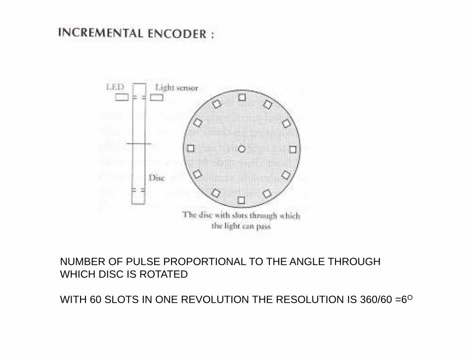
NUMBER OF PULSE PROPORTIONAL TO THE ANGLE THROUGH
WHICH DISC IS ROTATED
WITH 60 SLOTS IN ONE REVOLUTION THE RESOLUTION IS 360/60 =6O

ABSOLUTE ENCODER
USED TO MEASURE ANGULAR DISPLACEMENT
GIVES OUTPUT IN THE FORM OF BINARY NUMBER OF SEVERAL DIGITS,EACH
SUCH NUMBER REPRESENTING A PARTICULAR ANGULAR POSITION
TYPICAL ENCODER IS OF 10 TO 12 TRACKS
10 TRACKS =210 =1024 POSITION
RESOLUTION = 360/1024 = 0.35O

INORDER TO PREVENT MISALIGNMENT DUE TO TWO OR MORE BIT CHANGE,
SINGLE BIT CHANGE IS USED

STRAIN GUAGE
Bonded wire strain gauge
Displacement sensor
• Displacement sensors are basically used for the measurement of movement of an object.
• Potentiometer Sensors
• Strain Gauges
• Capacitive element based sensor
• Linear variable differential transformer (LVDT)

Potentiometer Sensors

• It works on the principle of conversion of mechanical displacement into an electrical signal.
• The sensor has a resistive element and a sliding contact (wiper). The slider moves along this conductive body, acting as a movable electric contact.

• The output voltage is proportional to the displacement of the slider over the wire
• Then the output parameter displacement is calibrated against the output voltage VA.

APPLICATIONmachine-tool controlsElevatorsautomobile throttle controlscontrol of injection molding machineswoodworking machineryPrintingSprayingrobotics

Strain GaugesThe strain in an element is a ratio of change in length in the direction of applied load to the original length of an element. The strain changes the resistance R of the element.∆R/R α ε; ∆R/R = G ε G is the constant of proportionality and is called as gauge factor. In general,
the value of G is considered in between 2 to 4 and the resistances are taken of the order of 100 Ω.
• These foils are made of Constantan alloy (copper-nickel 55-45% alloy) and are bonded to a backing material plastic (ployimide), epoxy or glass fiber reinforced epoxy.
Applications of strain gauges • Strain gauges are widely used in experimental stress analysis and diagnosis
on machines and failure analysis. • multi-axial stress fatigue testing• proof testing• residual stress• vibration measurement• torque measurement• bending • deflection measurement• Compression• tension measurement and strain measurement.

Capacitive element based sensor

• Capacitive sensor is of non-contact type sensor • primarily used to measure the linear
displacements from few millimeters to hundreds of millimeters
• It comprises of three plates, with the upper pair forming one capacitor and the lower pair another
• The linear displacement might take in two forms: one of the plates is moved by the
displacement so that the plate separation changes area of overlap changes due to the
displacement.

• The capacitance C of a parallel plate capacitor is given by, • C = εr εo A / d• where εr is the relative permittivity of the dielectric between the plates,
εo permittivity of free space, A area of overlap between two plates and d the plate separation
• Relative permittivity is the factor by which the electric field between the charges is decreased relative to vacuum
• The permittivity of free space (a vacuum) is a physical constant equal to approximately 8.85 x 10⁻¹² farad per meter (F/m)
• Capacitive elements can also be used as proximity sensor. The approach of the object towards the sensor plate is used for induction of change in plate separation. This changes the capacitance which is used to detect the object.
• Applications of capacitive element sensors • • Feed hopper level monitoring • Small vessel pump control • Grease
level monitoring • Level control of liquids • Metrology applications
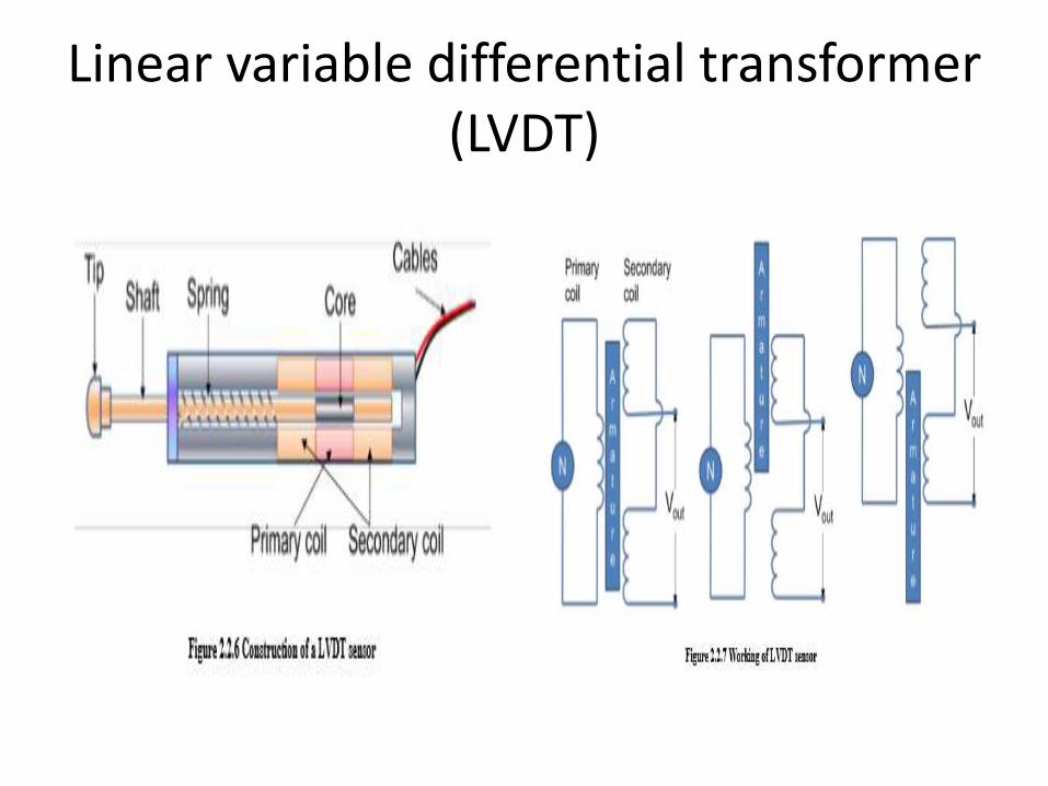
Linear variable differential transformer (LVDT)

• Linear variable differential transformer (LVDT) is a primary transducer used for measurement of linear displacement with an input range of about ± 2 to ± 400 mm in general.
• It has three coils symmetrically spaced along an insulated tube.
• The central coil is primary coil and the other two are secondary coils.
• Secondary coils are connected in series in such a way that their outputs oppose each other. A magnetic core attached to the element of which displacement is to be monitored is placed inside the insulated tube.

• Due to an alternating voltage input to the primary coil, alternating electromagnetic forces (emfs) are generated in secondary coils
• When the magnetic core is centrally placed with its half portion in each of the secondary coil regions then the resultant voltage is zero
• If the core is displaced from the central position as shown in Figure 2.2.7, say, more in secondary coil 1 than in coil 2, then more emf is generated in one coil
• If the magnetic core is further displaced, then the value of resultant voltage increases in proportion with the displacement

proximity sensors
• Proximity sensors are a type of position sensor and are used to trace when an object has moved with in particular critical distance of a transducer
• Eddy current proximity sensors
• Inductive proximity switch
• Optical encoders
• Pneumatic Sensors
• Proximity Switches
• Hall effect sensor

Eddy current proximity sensors

• Eddy current proximity sensors are used to detect non-magnetic but conductive materials
• They comprise of a coil, an oscillator, a detector and a triggering circuit• When an alternating current is passed thru this coil, an alternative
magnetic field is generated. If a metal object comes in the close proximity of the coil, then eddy currents are induced in the object due to the magnetic field
• These eddy currents create their own magnetic field which distorts the magnetic field responsible for their generation. As a result, impedance of the coil(The opposition to current flowing through a coil in an AC circuit is determined by the AC resistance, more commonly known as Impedance(Z), of the circuit) changes and so the amplitude of alternating current. This can be used to trigger a switch at some pre-determined level of change in current
• Applications of inductive proximity switches • Industrial automation: counting of products during production or transfer • Security: detection of metal objects, arms, land mines

Applications of eddy current proximity sensors
• Automation requiring precise location
• Machine tool monitoring
• Final assembly of precision equipment such as disk drives
• Measuring the dynamics of a continuously moving target, such as a vibrating element
• Drive shaft monitoring
• Vibration measurements

Inductive proximity switch

• Inductive proximity switches are basically used for detection of metallic objects
• components; the coil, oscillator, detection circuit and output circuit
• An alternating current is supplied to the coil which generates a magnetic field. When, a metal object comes closer to the end of the coil, inductance of the coil changes.

Optical encoders
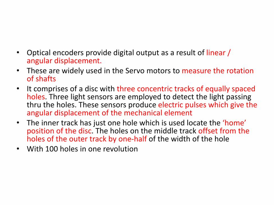
• Optical encoders provide digital output as a result of linear / angular displacement.
• These are widely used in the Servo motors to measure the rotation of shafts
• It comprises of a disc with three concentric tracks of equally spaced holes. Three light sensors are employed to detect the light passing thru the holes. These sensors produce electric pulses which give the angular displacement of the mechanical element
• The inner track has just one hole which is used locate the ‘home’ position of the disc. The holes on the middle track offset from the holes of the outer track by one-half of the width of the hole
• With 100 holes in one revolution

Pneumatic Sensors

• Pneumatic sensors are used to measure the displacement as well as to sense the proximity of an object close to it
• The displacement and proximity are transformed into change in air pressure.
• Low pressure air is allowed to escape through port A. In the absence of any obstacle / object
• However when an object obstructs the low pressure air (Port A), there is rise in pressure in output port B. This rise in pressure is calibrated to measure the displacement or to trigger a switch
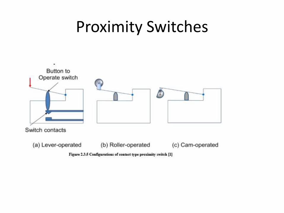
Proximity Switches

• These are small electrical switches which require physical contact and a small operating force to close the contacts

• Magnet based Reed switches are used as proximity switches. When a magnet attached to an object brought close to the switch, the magnetic reeds attract to each other and close the switch contacts.
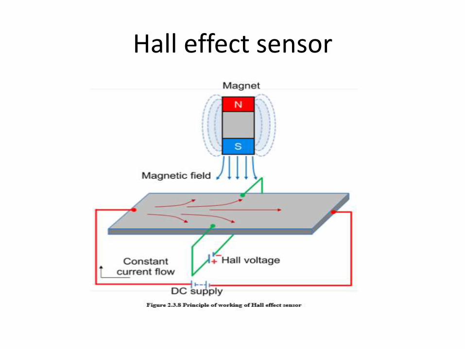
Hall effect sensor

• Hall effect sensors work on the principle that when a beam of charge particles passes through a magnetic field, forces act on the particles and the current beam is deflected from its straight line path
• Thus one side of the disc will become negatively charged and the other side will be of positive charge.

application
• The typical application of Hall effect sensor is the measurement of fluid level in a container. The container comprises of a float with a permanent magnet attached at its top. An electric circuit with a current carrying disc is mounted in the casing. When the fluid level increases, the magnet will come close to the disc and a potential difference generates. This voltage triggers a switch to stop the fluid to come inside the container.

Velocity, motion, force and pressure sensor

• Tachogenerator works on the principle of variable reluctance
• It consists of an assembly of a toothed wheel and a magnetic circuit
• Toothed wheel is mounted on the shaft or the element of which angular motion is to be measured.
• Magnetic circuit comprising of a coil wound on a ferromagnetic material core.
• As the wheel rotates, the air gap between wheel tooth and magnetic core changes which results in cyclic change in flux linked with the coil.
• The alternating emf generated is the measure of angular motion


• An alternating current (AC) generator can also be used as a techognerator
• It comprises of rotor coil which rotates with the shaft
• The rotor rotates in the magnetic field produced by a stationary permanent magnet or electromagnet.
• During this process, an alternating emf is produced which is the measure of the angular velocity of the rotor

Strain Gauge as force Sensor

• Strain gauge based sensors work on the principle of change in electrical resistance
• When, a mechanical element subjects to a tension or a compression the electric resistance of the material changes
• This is used to measure the force acted upon the element.
• Generally strain gauges are used to measure forces up to 10 MN. The non-linearity and repeatability errors of this transducer are ±0.03% and ±0.02% respectively

Fluid pressure

• Chemical, petroleum, power industry often need to monitor fluid pressure
• Various types of instruments such as diaphragms, capsules, and bellows are used to monitor the fluid pressure
• Specially designed strain gauges doped in diaphragms are generally used to measure the inlet manifold pressure in applications such as automobiles
• Specially designed strain gauges doped in diaphragms are generally used to measure the inlet manifold pressure in applications such as automobiles

Bellow with a LVDT

• A stack of capsules is called as ‘Bellows’. Bellows with a LVDT sensor measures the fluid pressure in terms of change in resultant voltage across the secondary coils of LVDT

Tactile sensors

• In general, tactile sensors are used to sense the contact of fingertips of a robot with an object
• They are also used in manufacturing of ‘touch display’ screens of visual display units (VDUs) of CNC machine tools
• the construction of piezo-electric polyvinylidene fluoride (PVDF) based tactile sensor
• It has two PVDF layers separated by a soft film which transmits the vibrations. An alternating current is applied to lower PVDF layer which generates vibrations due to reverse piezoelectric effect.
• These vibrations are transmitted to the upper PVDF layer via soft film. These vibrations cause alternating voltage across the upper PVDF layer
• pressure is applied on the upper PVDF layer the vibrations gets affected and the output voltage changes

Piezoelectric sensor

• Piezoelectric sensor is used for the measurement of pressure, acceleration and dynamic-forces such as oscillation, impact, or high speed compression or tension.
• It contains piezoelectric ionic crystal materials such as Quartz
• On application of force or pressure these materials get stretched or compressed.
• During this process, the charge over the material changes and redistributes
• One face of the material becomes positively charged and the other negatively charged.
• The net charge q on the surface is proportional to the amount x by which the charges have been displaced

Liquid flow1. Liquid flow is generally measured by applying the Bernoulli’s
principle of fluid flow through a constriction2. The quantity of fluid flow is computed by using the pressure drop
measured. The fluid flow volume is proportional to square root of pressure difference at the two ends of the constriction
• Orifice plate• Turbine meter etc.

• It has a disc with a hole at its center, through which the fluid flows.
• The pressure difference is measured between a point equal to the diameter of the tube upstream and a point equal to the half the diameter downstream.
• It exhibits nonlinear behavior and does not work with slurries. It has accuracy of ± 1.5%.
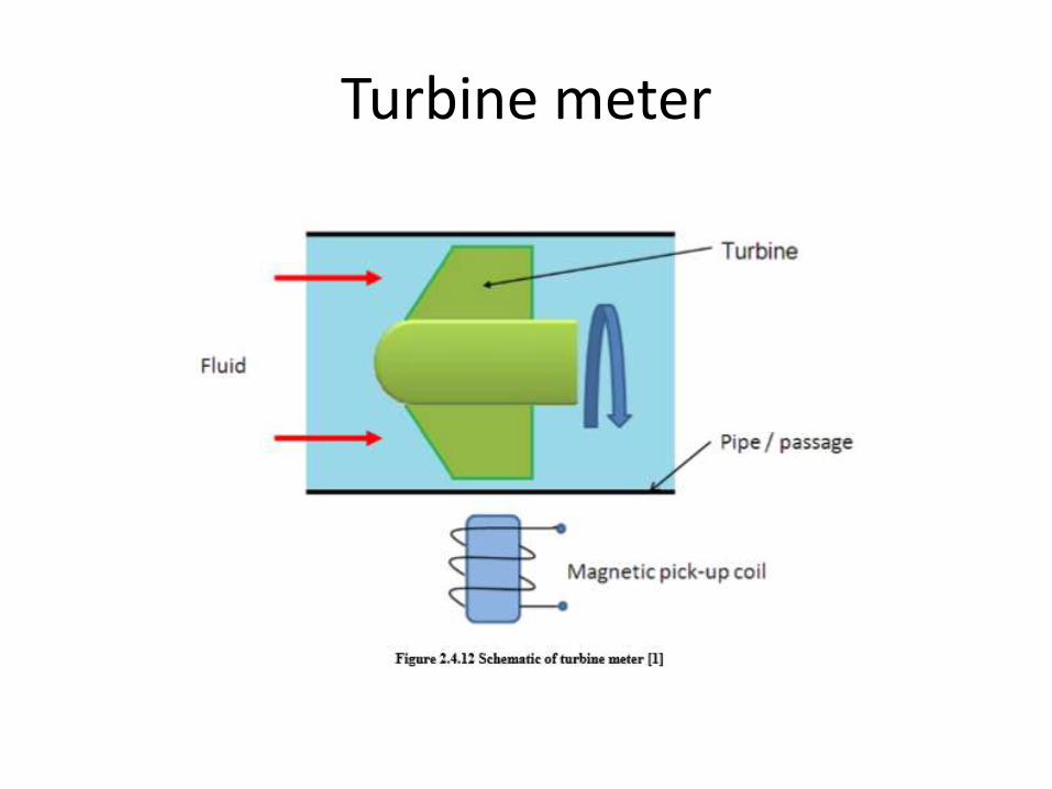
Turbine meter

• It has a multi blade rotor mounted centrally in the pipe along which the flow is to be measured
• The fluid flow rotates the rotor. Accordingly the magnetic pick up coil counts the number of magnetic pulses generated due to the distortion of magnetic field by the rotor blades.
• The angular velocity is proportional to the number of pulses and fluid flow is proportional to angular velocity.

Temperature and light sensors
• Temperature conveys the state of a mechanical system in terms of expansion or contraction of solids, liquids or gases, change in electrical resistance of conductors, semiconductors and thermoelectric emfs
• bimetallic strips
• Thermocouples
• thermistors


• Bimetallic strips are used as thermal switch in controlling the temperature or heat in a manufacturing process or system
• It contains two different metal strips bonded together
• The metals have different coefficients of expansion. On heating the strips bend into curved strips with the metal with higher coefficient of expansion on the outside of the curve

• As the strips bend, the soft iron comes in closer proximity of the small magnet and further touches.
• Then the electric circuit completes and generates an alarm.
• In this way bimetallic strips help to protect the desired application from heating above the pre-set value of temperature

Thermistors
• Thermistors follow the principle of decrease in resistance with increasing temperature.
• The material used in thermistor is generally a semiconductor material such as a sintered metal oxide (mixtures of metal oxides, chromium, cobalt, iron, manganese and nickel) or doped polycrystalline ceramic containing barium titanate(BaTiO3) and other compounds

• As the temperature of semiconductor material increases the number of electrons able to move about increases which results in more current in the material and reduced resistance
• Thermistors are available in the form of a bead (pressed disc), probe or chip
• It has a small bead of dimension from 0.5 mm to 5 mm coated with ceramic or glass material. The bead is connected to an electric circuit through two leads. To protect from the environment, the leads are contained in a stainless steel tube.
Applications of Thermistors • To monitor the coolant temperature and/or oil temperature inside
the engine • To monitor the temperature of an incubator• To control the operations of consumer appliances such as toasters,
coffee makers, refrigerators, freezers, hair dryers, etc.

Thermocouple
• Thermocouple works on the fact that when a junction of dissimilar metals heated, it produces an electric potential related to temperature As per Thomas Seebeck (1821),
• when two wires composed of dissimilar metals are joined at both ends and one of the ends is heated, then there is a continuous current which flows in the thermoelectric circuit
• The net open circuit voltage (the Seebeckvoltage) is a function of junction temperature and composition of two metals
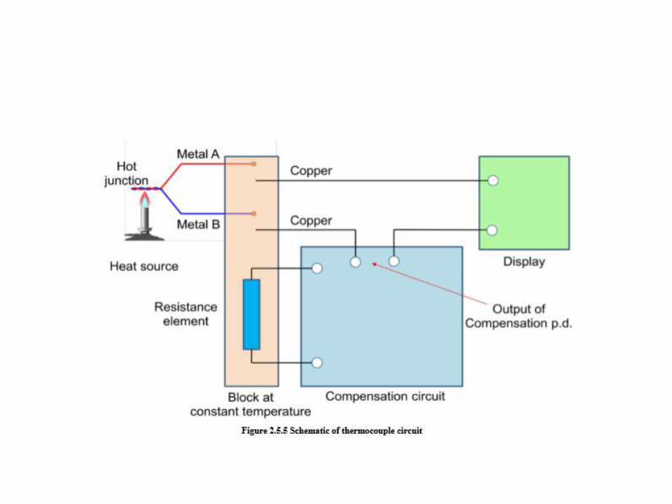

• Applications of Thermocouples • To monitor temperatures and chemistry throughout the steel making process • Testing temperatures associated with process plants e.g. chemical production and petroleum refineries • Testing of heating appliance safety

Light sensors
• A light sensor is a device that is used to detect light.
• There are different types of light sensors such as
• photocell/photoresistor
• photo diodes

Photoresistor

• Photoresistor is also called as light dependent resistor (LDR). • It has a resistor whose resistance decreases with increasing incident light intensity. • It is made of a high resistance semiconductor material, cadmium sulfide (CdS). • The resistance of a CdS photoresistor varies inversely to the amount of light
incident upon it.• Photoresistor follows the principle of photoconductivity which results from the
generation of mobile carriers when photons are absorbed by the semiconductor material.
• The CdS resistor coil is mounted on a ceramic substrate. This assembly is encapsulated by a resin material. The sensitive coil electrodes are connected to the control system though lead wires. On incidence of high intensity light on the electrodes, the resistance of resistor coil decreases which will be used further to generate the appropriate signal by the microprocessor via lead wires.
•

Applications of photo resistor
• • Computers, wireless phones, and televisions, use ambient light sensors to automatically control the brightness of a screen • Barcode scanners used in retailer locations work using light sensor technology • In space and robotics: for controlled and guided motions of vehicles and robots. The light sensor enables a robot to detect light. Robots can be programmed to have a specific reaction if a certain amount of light is detected. • Auto Flash for camera • Industrial process control
Photo diodes
• Photodiode is a solid-state device which converts incident light into an electric current
• It is made of Silicon. It consists of a shallow diffused p-n junction, normally a p-on-n configuration
• When photons of energy greater than 1.1eV (the bandgapof silicon) fall on the device, they are absorbed and electron-hole pairs are created
• The depth at which the photons are absorbed depends upon their energy. The lower the energy of the photons, the deeper they are absorbed.
• Then the electron-hole pairs drift apart. When the minority carriers reach the junction, they are swept across by the electric field and an electric current establishes.
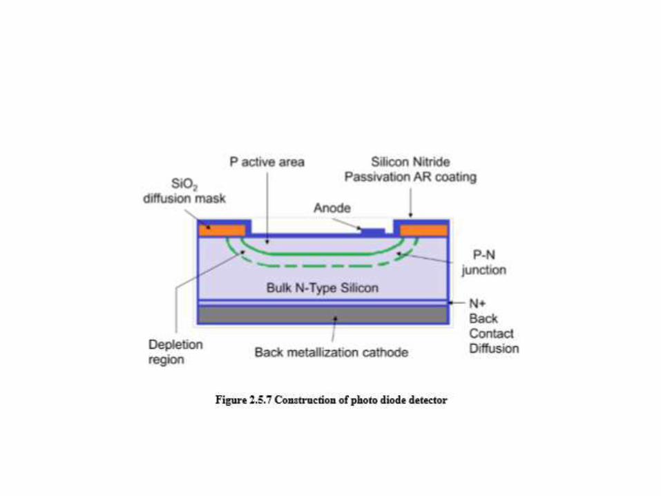

• Photodiodes are one of the types of photodetector, which convert light into either current or voltage
• It is constructed from single crystal silicon wafers. It is a p-n junction device. The upper layer is p layer
• It is very thin and formed by thermal diffusion or ion implantation of doping material such as boron. Depletion region is narrow and is sandwiched between p layer and bulk n type layer of silicon
• Light irradiates at front surface, anode, while the back surface is cathode. The incidence of light on anode generates a flow of electron across the p-n junction which is the measure of light intensity

• Applications of photo diodes • Camera: Light Meters, Automatic Shutter Control, Auto-focus, Photographic Flash Control •
• Medical: CAT Scanners - X ray Detection, Pulse Oximeters, Blood Particle Analyzers •
• Industry • Bar Code Scanners • Light Pens • Brightness Controls • Encoders • Position Sensors • Surveying Instruments • Copiers - Density of Toner Safety Equipment • Smoke Detectors • Flame Monitors • Security Inspection Equipment - Airport X ray • Intruder Alert - Security System
•
• NPTEL – Mechanical – Mechatronics and Manufacturing Automation •
• Joint initiative of IITs and IISc – Funded by MHRD Page 39 of 56 • Automotive • Headlight Dimmer • Twilight Detectors • Climate Control - Sunlight Detector •
• Communications • Fiber Optic Links • Optical Communications • Optical Remote Control