unit-1: crystal structure and crystal engineering of
TRANSCRIPT

Unit-1: Crystal Structure and Crystal Engineering of Organic Solids Close-Packing of Identical Spheres
Crystals are of course three-dimensional objects, exploring the properties of arrays in two-dimensional space. This will make it easier to develop the basic ideas without complication and to visualize in 3-D.
The interior of the square-packed array is in contact with four other marbles, while this number rises to six in the hexagonal-packed arrangement. It should also be apparent that the latter scheme covers a smaller area (contains less empty space) and is therefore a more efficient packing arrangement. If you are good at geometry, you can show that square packing covers 78 percent of the area, while hexagonal packing yields 91 percent coverage.
If the atoms are identical and are bound together mainly by dispersion forces which
are completely non-directional, they will favor a structure in which as many atoms can be in direct contact as possible. This will, of course, be the hexagonal arrangement.
Directed chemical bonds between atoms have a major effect on the packing. The version of hexagonal packing shown at the right occurs in the form of carbon known as graphite which forms 2-dimensional sheets. Each carbon atom within a sheet is bonded to three other carbon atoms. The result is just the basic hexagonal structure with some atoms missing.
The coordination number of 3 reflects the sp2-hybridization of carbon in graphite, resulting in plane-trigonal bonding and thus the sheet structure. Adjacent sheets are bound by weak dispersion forces, allowing the sheets to slip over one another and giving rise to the lubricating and flaking properties of graphite. Lattices
The underlying order of a crystalline solid can be represented by an array of regularly spaced points that indicate the locations of the crystal's basic structural units. This array is called a crystal lattice. Crystal lattices can be thought of as being built up from repeating units containing just a few atoms. These repeating units act much as a rubber stamp: press it on the paper, move ("translate") it by an amount equal to the lattice spacing, and stamp the paper again.

The gray circles represent a square array of lattice points.
The orange square is the simplest unit cell that can be used to define the 2-
dimensional lattice.
Building out the lattice by moving ("translating") the unit cell in a series of steps,
Although real crystals do not actually grow in this manner, this process is
conceptually important because it allows us to classify a lattice type in terms of the simple repeating unit that is used to "build" it. We call this shape the unit cell. Any number of primitive shapes can be used to define the unit cell of a given crystal lattice. The one that is actually used is largely a matter of convenience, and it may contain a lattice point in its centre, as you see in two of the unit cells shown here. In general, the best unit cell is the simplest one that is capable of building out the lattice.
Shown above are unit cells for the close-packed square and hexagonal lattices. Although we could use a hexagon for the second of these lattices, the rhombus is preferred because it is simpler.

Notice that in both of these lattices, the corners of the unit cells are centred on a lattice
point. This means that an atom or molecule located on this point in a real crystal lattice is shared with its neighbouring cells. As is shown more clearly here for a two-dimensional square-packed lattice, a single unit cell can claim "ownership" of only one-quarter of each molecule, and thus "contains" 4 × ¼ = 1 molecule.
The unit cell of the graphite form of carbon is also a rhombus, in keeping with the hexagonal symmetry of this arrangement. Notice that to generate this structure from the unit cell, we need to shift the cell in both the x- and y- directions in order to leave empty spaces at the correct spots. We could alternatively use regular hexagons as the unit cells, but the x+y shifts would still be required, so the simpler rhombus is usually preferred. As you will see in the next section, the empty spaces within these unit cells play an important role when we move from two- to three-dimensional lattices. Cubic Crystals
In order to keep this lesson within reasonable bounds, we are limiting it mostly to crystals belonging to the so-called cubic system. In doing so, we can develop the major concepts that are useful for understanding more complicated structures (as if there are not enough complications in cubics alone!) But in addition, it happens that cubic crystals are very commonly encountered; most metallic elements have cubic structures, and so does ordinary salt, sodium chloride.
We usually think of a cubic shape in terms of the equality of its edge lengths and the
90° angles between its sides. For example, you can rotate a cube 90° around an axis perpendicular to any pair of its six faces without making any apparent change to it. We say that the cube possesses three mutually perpendicular four-fold rotational axes, abbreviated C4 axes. But if you think about it, a cube can also be rotated around the axes that extend

between opposite corners; in this case, it takes three 120° rotations to go through a complete circle, so these axes (also four in number) are three-fold or C3 axes.
Cubic crystals belong to one of the seven crystal systems whose lattice points can be extended indefinitely to fill three-dimensional space and which can be constructed by successive translations (movements) of a primitive unit cell in three dimensions. As we will see below, the cubic system, as well as some of the others, can have variants in which additional lattice points can be placed at the center of the unit or at the center of each face. The three types of cubic lattices
Structural examples of all three are known, with body- and face-centered (BCC and FCC) being much more common; most metallic elements crystallize in one of these latter forms. But although the simple cubic structure is uncommon by itself, it turns out that many BCC and FCC structures composed of ions can be regarded as interpenetrating combinations of two simple cubic lattices, one made up of positive ions and the other of negative ions. Notice that only the FCC structure, which we will describe below, is a close-packed lattice within the cubic system. Close-packed lattices in three dimensions
Close-packed lattices allow the maximum amount of interaction between atoms. If these interactions are mainly attractive, then close-packing usually leads to more energetically stable structures. These lattice geometries are widely seen in metallic, atomic, and simple ionic crystals.
As we pointed out above, hexagonal packing of a single layer is more efficient than square-packing, so this is where we begin. Imagine that we start with the single layer of green atoms shown below. We will call this the A layer. If we place a second layer of atoms (orange) on top of the A-layer, we would expect the atoms of the new layer to nestle in the hollows in the first layer. But if all the atoms are identical, only some of these void spaces will be accessible.
In the diagram on the left, notice that there are two classes of void spaces between the A atoms; one set has a vertex pointing up, while the other set has down-pointing vertices. Each void space constitutes a depression in which atoms of a second layer (the B-layer) can nest. The two sets of void spaces are completely equivalent, but only one of these sets can be

occupied by a second layer of atoms whose size is similar to those in the bottom layer. In the illustration on the right above we have arbitrarily placed the B-layer atoms in the blue voids, but could just as well have selected the white ones. Two choices for the third layer lead to two different close-packed lattice types
Now consider what happens when we lay down a third layer of atoms. These will fit into the void spaces within the B-layer. As before, there are two sets of these positions, but unlike the case described above, they are not equivalent.
The atoms in the third layer are represented by open blue circles in order to avoid
obscuring the layers underneath. In the illustration on the left, this third layer is placed on the B-layer at locations that are directly above the atoms of the A-layer, so our third layer is just another A layer. If we add still more layers, the vertical sequence A-B-A-B-A-B-A... repeats indefinitely.
In the diagram on the right above, the blue atoms have been placed above the white (unoccupied) void spaces in layer A. Because this third layer is displaced horizontally (in our view) from layer A, we will call it layer C. As we add more layers of atoms, the sequence of layers is A-B-C-A-B-C-A-B-C..., so we call it ABC packing.
For the purposes of clarity, only three atoms of the A and C layers are shown in these
diagrams. But in reality, each layer consists of an extended hexagonal array; the two layers are simply displaced from one another.
These two diagrams that show exploded views of the vertical stacking further illustrate the rather small fundamental difference between these two arrangements— but, as you will see below, they have widely divergent structural consequences. Note the opposite orientations of the A and C layers The Hexagonal closed-packed structure
The HCP stacking shown on the left just above takes us out of the cubic crystal system into the hexagonal system, so we will not say much more about it here except to point out each atom has 12 nearest neighbors: six in its own layer, and three in each layer above and below it.

The cubic close-packed structure Below we reproduce the FCC structure that was shown above.
The B-layer atoms form a hexagon, but this is a cubic structure. The FCC stack is inclined with respect to the faces of the cube, and is in fact coincident with one of the three-fold axes that passes through opposite corners. It requires a bit of study to see the relationship, and we have provided two views to help you. The one on the left shows the cube in the normal isometric projection; the one on the right looks down upon the top of the cube at a slightly inclined angle.
Both the CCP and HCP structures fill 74 percent of the available space when the atoms have the same size. You should see that the two shaded planes cutting along diagonals within the interior of the cube contain atoms of different colors, meaning that they belong to different layers of the CCP stack. Each plane contains three atoms from the B layer and three from the C layer, thus reducing the symmetry to C3, which a cubic lattice must have.

The FCC unit cell The figure below shows the the face-centered cubic unit cell of a cubic-close packed
lattice.
Each corner atom is shared with eight adjacent unit cells and so a single unit cell can claim only 1/8 of each of the eight corner atoms. Similarly, each of the six atoms centered on a face is only half-owned by the cell. The grand total is then (8 × 1/8) + (6 × ½) = 4 atoms per unit cell. Interstitial Void Spaces The atoms in each layer in these close-packing stacks sit in a depression in the layer below it. As we explained above, these void spaces are not completely filled. (It is geometrically impossible for more than two identical spheres to be in contact at a single point.) We will see later that these interstitial void spaces can sometimes accommodate additional (but generally smaller) atoms or ions.
If we look down on top of two layers of close-packed spheres, we can pick out two classes of void spaces which we call tetrahedral and octahedral holes. Common cubic close-packed structures
It can be shown from elementary trigonometry that an atom will fit exactly into an octahedral site if its radius is 0.414 as great as that of the host atoms. The corresponding figure for the smaller tetrahedral holes is 0.225.
Many pure metals and compounds form face-centered cubic (cubic close- packed) structures. The existence of tetrahedral and octahedral holes in these lattices presents an opportunity for "foreign" atoms to occupy some or all of these interstitial sites. In order to retain close-packing, the interstitial atoms must be small enough to fit into these holes without disrupting the host CCP lattice. When these atoms are too large, which is commonly the case in ionic compounds, the atoms in the interstitial sites will push the host atoms apart so that the face-centered cubic lattice is somewhat opened up and loses its close-packing character. The rock-salt structure
Alkali halides that crystallize with the "rock-salt" structure exemplified by sodium chloride can be regarded either as a FCC structure of one kind of ion in which the octahedral holes are occupied by ions of opposite charge, or as two interpenetrating FCC lattices made up of the two kinds of ions. The two shaded octahedra illustrate the identical coordination of the two kinds of ions; each atom or ion of a given kind is surrounded by six of the opposite kind, resulting in a coordination expressed as (6:6).

How many NaCl units are contained in the unit cell? If we ignore the atoms that were placed outside the cell in order to construct the octahedra, you should be able to count fourteen "orange" atoms and thirteen "blue" ones. But many of these are shared with adjacent unit cells.
An atom at the corner of the cube is shared by eight adjacent cubes, and thus makes a 1/8 contribution to any one cell. Similarly, the center of an edge is common to four other cells, and an atom centered in a face is shared with two cells. Taking all this into consideration, you should be able to confirm the following tally showing that there are four AB units in a unit cell of this kind.
Orange Blue
8 at corners: 8 x 1/8 = 1 12 at edge centers: 12 x ¼ = 3 6 at face centers: 6 x ½ = 3 1 at body center = 1 total: 4 total: 4
If we take into consideration the actual sizes of the ions (Na+ = 116 pm, Cl– =
167 pm), it is apparent that neither ion will fit into the octahedral holes with a CCP lattice composed of the other ion, so the actual structure of NaCl is somewhat expanded beyond the close-packed model.
The space-filling model on the right depicts a face-centered cubic unit cell of chloride ions (purple), with the sodium ions (green) occupying the octahedral sites. The zinc-blende structure: using some tetrahedral holes
Since there are two tetrahedral sites for every atom in a close-packed lattice, we can have binary compounds of 1:1 or 1:2 stoichiometry depending on whether half or all of the tetrahedral holes are occupied. Zinc-blende is the mineralogical name for zinc sulfide, ZnS. An impure form known as sphalerite is the major ore from which zinc is obtained.

This structure consists essentially of a FCC (CCP) lattice of sulfur atoms (orange) (equivalent to the lattice of chloride ions in NaCl) in which zinc ions (green) occupy half of the tetrahedral sites. As with any FCC lattice, there are four atoms of sulfur per unit cell, and the the four zinc atoms are totally contained in the unit cell. Each atom in this structure has fournearest neighbors, and is thus tetrahedrally coordinated. It is interesting to note that if all the atoms are replaced with carbon, this would correspond to the diamond structure. The fluorite structure: all tetrahedral sites occupied
Fluorite, CaF2, having twice as many ions of fluoride as of calcium, makes use of all eight tetrahedral holes in the CPP lattice of calcium ions (orange) depicted here. To help you understand this structure, we have shown some of the octahedral sites in the next cell on the right; you can see that the calcium ion at A is surrounded by eight fluoride ions, and this is of course the case for all of the calcium sites. Since each fluoride ion has four nearest-neighbor calcium ions, the coordination in this structure is described as (8:4).
Although the radii of the two ions (F–= 117 pm, Ca2+ = 126 pm does not allow true close packing, they are similar enough that one could just as well describe the structure as a FCC lattice of fluoride ions with calcium ions in the octahedral holes. Simple- and body-centered cubic structures
In Section 4 we saw that the only cubic lattice that can allow close packing is the face-centered cubic structure. The simplest of the three cubic lattice types, the simple cubic lattice, lacks the hexagonally-arranged layers that are required for close packing. But as shown in this exploded view, the void space between the two square-packed layers of this cell constitutes an octahedral hole that can accommodate another atom, yielding a packing

arrangement that in favorable cases can approximate true close-packing. Each second-layer B atom (blue) resides within the unit cell defined the A layers above and below it.
The A and B atoms can be of the same kind or they can be different. If they are the same, we have a body-centered cubic lattice. If they are different, and especially if they are oppositely-charged ions (as in the CsCl structure), there are size restrictions: if the B atom is too large to fit into the interstitial space, or if it is so small that the A layers (which all carry the same electric charge) come into contact without sufficient A-B coulombic attractions, this structural arrangement may not be stable. The cesium chloride structure
CsCl is the common model for the BCC structure. As with so many other structures involving two different atoms or ions, we can regard the same basic structure in different ways. Thus if we look beyond a single unit cell, we see that CsCl can be represented as two interpenetrating simple cubic lattices in which each atom occupies an octahedral hole within the cubes of the other lattice.
Hexagonal Close Packed Crystal Structure (HCP)
If you look at the figure below, you might think that hexagon close-packed crystal structure is more complicated than face-centered cubic crystal structure. In fact, it is a simpler structure. Think back to the last section where we constructed first one layer of atoms and then a second layer of atoms for face-centered cubic structure. Now, for hexagonal close-packed crystal structure, we do not construct a third layer. Instead, the third layer is simply the first layer repeated, the fourth layer is the second layer repeated, and so on and so on as shown in the figure below.
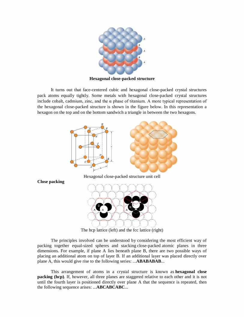
Hexagonal close-packed structure
It turns out that face-centered cubic and hexagonal close-packed crystal structures
pack atoms equally tightly. Some metals with hexagonal close-packed crystal structures include cobalt, cadmium, zinc, and the α phase of titanium. A more typical representation of the hexagonal close-packed structure is shown in the figure below. In this representation a hexagon on the top and on the bottom sandwich a triangle in between the two hexagons.
Hexagonal close-packed structure unit cell
Close packing
The hcp lattice (left) and the fcc lattice (right)
The principles involved can be understood by considering the most efficient way of
packing together equal-sized spheres and stacking close-packed atomic planes in three dimensions. For example, if plane A lies beneath plane B, there are two possible ways of placing an additional atom on top of layer B. If an additional layer was placed directly over plane A, this would give rise to the following series: ...ABABABAB...
This arrangement of atoms in a crystal structure is known as hexagonal close
packing (hcp). If, however, all three planes are staggered relative to each other and it is not until the fourth layer is positioned directly over plane A that the sequence is repeated, then the following sequence arises: ...ABCABCABC...

This type of structural arrangement is known as cubic close packing (ccp). The unit
cell of a ccp arrangement of atoms is the face-centered cubic (fcc) unit cell. This is not immediately obvious as the closely packed layers are parallel to the {111} planes of the fcc unit cell. There are four different orientations of the close-packed layers. The packing efficiency can be worked out by calculating the total volume of the spheres and dividing by the volume of the cell as follows: The 74% packing efficiency is the maximum density possible in unit cells constructed of spheres of only one size. Most crystalline forms of metallic elements are hcp, fcc, or bcc (body-centered cubic). The coordination number of atoms in hcp and fcc structures is 12 and its atomic packing factor (APF) is the number mentioned above, 0.74. This can be compared to the APF of a bcc structure, which is 0.68. Crystal Structures Fundamental Concepts
Atoms self-organize in crystals, most of the time. The crystalline lattice, is a periodic array of the atoms. When the solid is not crystalline, it is called amorphous. Examples of crystalline solids are metals, diamond and other precious stones, ice, graphite. Examples of amorphous solids are glass, amorphous carbon (a-C), amorphous Si, most plastics To discuss crystalline structures it is useful to consider atoms as being hard spheres, with well-defined radii. In this scheme, the shortest distance between two like atoms is one diameter. Unit Cells
The unit cell is the smallest structure that repeats itself by translation through the crystal. We construct these symmetrical units with the hard spheres. The most common types of unit cells are the faced-centered cubic (FCC), the body-centered cubic (FCC) and the hexagonal close-packed (HCP). Other types exist, particularly among minerals. The simple cube (SC) is often used for didactical purpose, no material has this structure. The closest packed direction in a BCC cell is along the diagonal of the cube; in a FCC cell is along the diagonal of a face of the cube. Polymorphism and Allotropy
Some materials may exist in more than one crystal structure, this is called polymorphism. If the material is an elemental solid, it is called allotropy. An example of allotropy is carbon, which can exist as diamond, graphite, and amorphous carbon. Close-Packed Crystal Structures
The FCC and HCP are related, and have the same APF. They are built by packing spheres on top of each other, in the hollow sites). The packing is alternate between two types of sites, ABABAB in the HCP structure, and alternates between three types of positions, ABCABC in the FCC crystals. Crystalline and Non-Crystalline Materials Single Crystals
Crystals can be single crystals where the whole solid is one crystal. Then it has a regular geometric structure with flat faces.

Polycrystalline Materials A solid can be composed of many crystalline grains, not aligned with each other. It is
called polycrystalline. The grains can be more or less aligned with respect to each other. Where they meet is called a grain boundary. Anisotropy
Different directions in the crystal have a different packing. For instance, atoms along the edge FCC crystals are more separated than along the face diagonal. This causes anisotropy in the properties of crystals; for instance, the deformation depends on the direction in which a stress is applied. X-Ray Diffraction Determination of Crystalline Structure – not covered Non-Crystalline Solids
In amorphous solids, there is no long-range order. But amorphous does not mean random, since the distance between atoms cannot be smaller than the size of the hard spheres. Also, in many cases there is some form of short-range order. For instance, the tetragonal order of crystalline SiO2 (quartz) is still apparent in amorphous SiO2 (silica glass.) Body Centred Cubic Structure
At room temperatures, elements Li, Na, K, Rb, Ba, V, Cr and Fe have structures that can be described as body centre cubic (bcc) packing of spheres. The other two common ones are face centred cubic (fcc) and hexagonal closest (hcp) packing. This type of structure is shown by the diagram below. In a crystal structure, the arrangement extends over millions and millions of atoms, and the above diagram shows the unit cell, the smallest unit that, when repeatedly stacked together, will generate the entire structure.
Actually, the unit we draw is more than a unit
cell. We use the centre of the atoms (or spheres) to represent the corners of the unit cell, and each of these atoms are shared by 8 unit cells. There is a whole atom located in the centre of the unit cell. Usually, the length of the cell edge is represented by a. The direction from a corner of a cube to the farthest corner is called body diagonal (bd). The face diagonal (fd) is a line drawn from one vertex to the opposite corner of the same face. If the edge is a, then we have: fd2 = a2 + a2 = 2 a2 bd2 = fd2 + a2 = a2 + a2 + a2 = 3 a2
Atoms along the body diagonal (bd) touch each other. Thus, the body diagonal has a length that is four times the radius of the atom, R. bd = 4 R
The relationship between a and R can be worked out by the Pythagorean theorem: (4 R)2 = 3 a2 Thus,

4 R = sqrt(3) a or a = 4R/sqrt(3)
Recognizing these relationships enable you to calculate parameters for this type of crystal. For example, one of the parameter is the packing fraction, the fraction of volume occupied by the spheres in the structure. Face Centered Cubic Structure (FCC)
If, instead of starting with a square, we start with a triangle and continue to add atoms, packing as tightly as we can, we will end up with a layer of atoms as shown in the figure below.
First layer of hexagonal structure
Now let me put an atom on top of that first layer over one of the 'B' positions and let it
rest down into one of the valleys. I can now place two more atoms in nearby 'B' positions so that each will rest in their own valley in such a way that all three atoms will touch and form a triangle. Now let me add more atoms to the second layer, packing them in as tightly as possible. These two layers are shown in the figure below. If you look closely, you should be able to see that the second layer only covers half of the valleys produced by the first layer. The 'C' valleys are left uncovered. In fact, half of the valleys of the second layer line up with the unoccupied 'C' valleys of the first layer.
First and second layer of hexagonal structure
Now let’s put a third layer where the atoms are placed where the unoccupied valleys
of the first two layers lineup, the 'C' valleys. It is a little difficult to visualize, but if one of the top layer atoms is one corner of our cube and that corner is pointing out then we obtain the cube shown in the figure below.

Complete three layer hexagonal structure
This crystal structure is known as face-centered cubic and has atoms at each corner of
the cube and six atoms at each face of the cube. It is shown in the figure below. This structure, as well as the next structure we are going to discuss, has the atoms packed as tightly as theoretically possible. Metals that possess face-centered cubic structure include copper, aluminum, silver, and gold.
Face centred cubic (fcc) structure
Cation-anion radius ratio
Critical Radius Ratio. This diagram is for coordination number six: 4 anions in the plane shown, 1 above the plane and 1 below. The stability limit is at rC/rA = 0.414
In condensed matter physics and inorganic chemistry the cation-anion radius ratio is the ratio of the ionic radius of the cation to the ionic radius of the anion in a cation-anion compound. According to Pauling's rules for crystal structures, the allowed size of the

cation for a given structure is determined by the critical radius ratio. If the cation is too small, then it will attract the anions into each other and they will collide hence the compound will be unstable due to anion-anion repulsion; this occurs when the radius ratio drops below 0.155. At the stability limit the cation is touching all the anions and the anions are just touching at their edges (radius ratio = 0.155). For radius ratios greater than 0.155, the compound may be stable. The table below gives the relation between radius ratio and coordination number, which may be obtained from a simple geometrical proof.
Radius Ratio Coordination number Type of void Example < 0.155 2 Linear
0.155 - 0.225 3 Triangular Planar B2O3
0.225 - 0.414 4 Tetrahedral ZnS, CuCl 0.414 - 0.732 6 Octahedral NaCl, MgO 0.732 - 1.000 8 Cubic CsCl, NH4Br
Polyhedron
"Polyhedra" redirects here. For the relational database system, see Polyhedra DBMS. For the game magazine, see Polyhedron (magazine). For the scientific journal, see Polyhedron (journal). For the occlusion bodies in Baculovirus infection, see Polyhedrin.
Examples of polyhedra
Regular tetrahedron
Small stellated dodecahedron
Icosidodecahedron
Great cubicuboctahedron
Rhombic triacontahedron
A toroidal polyhedron
In geometry, a polyhedron is a solid in three dimensions with flat polygonal faces, straight edges and sharp corners or vertices. The word polyhedron comes from the classical greek, as polyhedron. A convex polyhedron is the convex hull of finitely many points, not all on the same plane. Cubes and pyramids are examples of convex polyhedra. A polyhedron is a 3-dimensional example of the more general polytope in any number of dimensions. Sodium Oxide
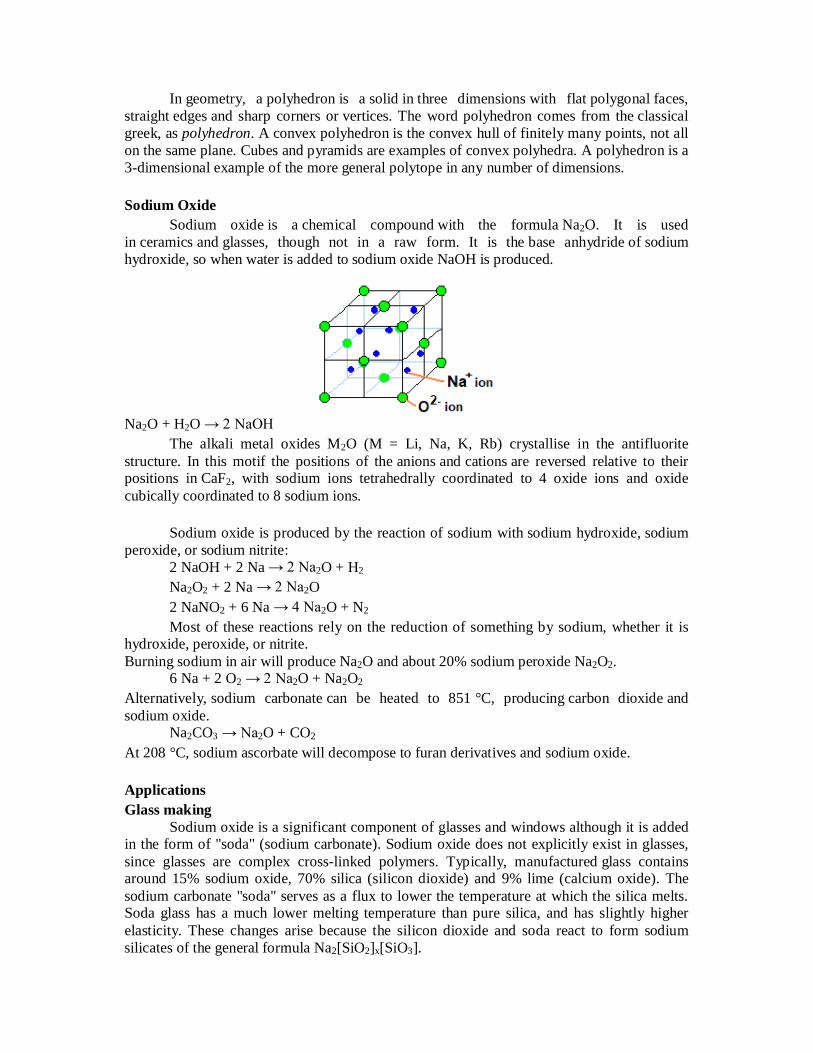
Sodium oxide is a chemical compound with the formula Na2O. It is used in ceramics and glasses, though not in a raw form. It is the base anhydride of sodium hydroxide, so when water is added to sodium oxide NaOH is produced.
Na2O + H2O → 2 NaOH
The alkali metal oxides M2O (M = Li, Na, K, Rb) crystallise in the antifluorite structure. In this motif the positions of the anions and cations are reversed relative to their positions in CaF2, with sodium ions tetrahedrally coordinated to 4 oxide ions and oxide cubically coordinated to 8 sodium ions.
Sodium oxide is produced by the reaction of sodium with sodium hydroxide, sodium peroxide, or sodium nitrite:
2 NaOH + 2 Na → 2 Na2O + H2 Na2O2 + 2 Na → 2 Na2O 2 NaNO2 + 6 Na → 4 Na2O + N2 Most of these reactions rely on the reduction of something by sodium, whether it is
hydroxide, peroxide, or nitrite. Burning sodium in air will produce Na2O and about 20% sodium peroxide Na2O2.
6 Na + 2 O2 → 2 Na2O + Na2O2 Alternatively, sodium carbonate can be heated to 851 °C, producing carbon dioxide and sodium oxide.
Na2CO3 → Na2O + CO2 At 208 °C, sodium ascorbate will decompose to furan derivatives and sodium oxide. Applications Glass making
Sodium oxide is a significant component of glasses and windows although it is added in the form of "soda" (sodium carbonate). Sodium oxide does not explicitly exist in glasses, since glasses are complex cross-linked polymers. Typically, manufactured glass contains around 15% sodium oxide, 70% silica (silicon dioxide) and 9% lime (calcium oxide). The sodium carbonate "soda" serves as a flux to lower the temperature at which the silica melts. Soda glass has a much lower melting temperature than pure silica, and has slightly higher elasticity. These changes arise because the silicon dioxide and soda react to form sodium silicates of the general formula Na2[SiO2]x[SiO3].

Na2CO3 → Na2O + CO2 Na2O + SiO2 → Na2SiO3 A. Simple Cubic Cell
As you rotate the spacefill model around you will notice that all the spheres (ions or atoms) are in contact with each other. Observe that in the simple cubic cell the edge equals two atomic radii. The volume of the unit cell then is the edge cubed (edge3). But the unit cell only contains, on the lattice points, an eighth of the volume of the sphere (ion or atoms). Because there are a total of eight one eighth volume spheres in the cell the simple cubic unit contains one net particle. One important question should be asked: what is the efficiency of packing same size atoms in simple cubes?
B. Body-centered Cubic Cell
Rotate the body-centered cubic (bcc) unit cell. As the name suggests it contains an ion or atom in the center of the cube. If all the spheres have the same radius, like in metals, then the spheres centered on the lattice points do not make contact with each other. Another way of looking at the layout is using 2-dimensional layer diagrams. The bcc has 3 layers (along the z-axis), which would look like this:
So in this case the edge is greater than two atomic radii of the lattice corners. To determine the edge value we must rely on the diagonal of the two opposite corners of the unit cell. This cube diagonal is 4 atom radius. The number of particles in a bcc unit cell is 2, determined as follows: 8 spheres on the lattice corners each with an eighth of their volume within the cell and one sphere completely embedded in the lattice.
We might expect to have a greater packaging efficiency because there are more particles within the lattice compared to a simple cubic cell. But we should realize that the lattice volume has increased accordingly. The ratio of the volumes where all particles are

equal gives us a 68.0%. Potassium (alkali metal) and iron are examples of metals that arrange themselves in bcc.
The virus that causes foot and mouth disease in animals also exhibits bcc crystal arrangements. C. Face-centered Cubic Cell
Illustrated left is the face-centered cubic (fcc) unit cell. It has a particle in the middle of each of the six faces of the cube. The two-dimensional layer representation shows that there are six particles which have half of their volumes within the lattice. The total number of particles within the lattice can be calculated as follows: 8 particles on the lattice corners, 6 particles with half of their volumes within the lattice. This gives us a total of 4. alculation of the edge value is quite straightforward.
Face-centered cubic cells have a 74.0% packaging efficiency for spheres or ions of
equal diameter. Some examples of fcc arrangements are: aluminum, copper and buckminsterfullerenes C60. It is crucial that we consider that there are holes within these lattices which can be filled with smaller ions or particles - we will see this later - thus increasing packaging efficiency. Compounds like salts fulfill this requirement. Ions of opposite charge can occupy these spaces. The result is an organized three-dimensional arrangement of ions and counter-ions. D. Ionic Compounds
Ionic compounds are made up of anions and cations. Usually the larger anions make up the framework of the crystal lattice and the smaller cations then occupy the spaces or holes left between the framework of anions. Packing arrangements like simple cubic (sc), cubic close-packed (ccp), hexagonal close-packed (hcp) are examples of structures which minimize same charge interactions. The Simple Cubic Hole
Let's start with anions packing in simple cubic cells. As you can see in Figure 6 the cation can sit in the hole where 8 anions pack. An example of this packing is CsCl (See the CsCl file left; Cl- yellow, Cs+ green). This lattice framework is arrange by the chloride ions forming a cubic structure. The smaller cesium cation sits in the hole surrounded by 8 chloride ions. Alternatively, it can be viewed as a chloride anion surrounded by 8 cesium cations. Both have coordination number 8. Each unit cell has one cesium ion and one chloride ion.
The cubic hole is quite large. Compare the sizes of Cs+ (1.69 Å) to Cl- (1.81 Å). It is convenient at this point to clarify the misconception concerning CsCl arrangement. Cesium chloride does not pack in a body-centered cubic structure. In a body-centered cubic structure all the atoms in the unit cell are identical (See section on Body- centered Cubic Cell). As you

may have noticed the cation occupying the center of the cube is smaller than the anions on the corners of the cube.
Cesium oxide
Cesium oxide describes inorganic compounds composed of cesium and oxygen. The following binary oxides of cesium are known: Cs11O3, Cs4O, Cs7O, and Cs2O. Both the oxide and suboxides are brightly coloured. The species Cs2O forms yellow-orange hexagonal crystals.
Cesium oxide is used in photo cathodes to detect infrared signals in devices such
as image intensifiers, vacuum photodiodes, photomultipliers, and TV camera tubes L. R. Koller described the first modern photo emissive surface in 1929–30 as a layer of cesium on a layer of cesium oxide on a layer of silver. It is a good electron emitter; however, its high vapor pressure limits its usefulness. Elemental magnesium reduces cesium oxide to elemental cesium, forming magnesium oxide as a side-product.
Cs2O + Mg → 2Cs + MgO Cs2O is hygroscopic, forming the corrosive CsOH on contact with water. Rutile
Rutile is a mineral composed primarily of titanium dioxide, TiO2. Rutile is the most common natural form of TiO2. Many rarer polymorphs of TiO2 are known:
anatase (sometimes known by the name "octahedrite"), a metastable tetragonal mineral of pseudo-octahedral habit;
brookite, an orthorhombic mineral; TiO2 (B), a monoclinic form.[5] (akaogiite and riesite are the very current monoclinic
new adds)

Rutile has one of the highest refractive indices at visible wavelengths of any known crystal and also exhibits a particularly large birefringence and high dispersion. Owing to these properties, it is useful for the manufacture of certain optical elements, especially polarization optics, for longer visible and infrared wavelengths up to about 4.5 µm. Natural rutile may contain up to 10% iron and significant amounts of niobium and tantalum. Rutile derives its name from the Latin rutilus, red, in reference to the deep red color observed in some specimens when viewed by transmitted light.
Rutile has a tetragonal unit cell, with unit cell parameters a = b = 4.584 Å, and c =
2.953 Å. The titanium cations have a coordination number of 6, meaning they are surrounded by an octahedron of 6 oxygen atoms. The oxygen anions have a coordination number of 3, resulting in a trigonal planar coordination. Rutile also shows a screw axis when its octahedra are viewed sequentially.
Rutile crystals are most commonly observed to exhibit a prismatic or acicular growth
habitwith preferential orientation along their c axis, the [001] direction. This growth habit is favored as the {110} facets of rutile exhibit the lowest surface free energy and are therefore thermodynamically most stable. The c-axis oriented growth of rutile appears clearly in nanorods, nanowires and abnormal grain growth phenomena of this phase. Perovskite
A perovskite is any material with the same type of crystal structure as calcium titanium oxide (CaTiO3), known as the perovskite structure, or XIIA2+VIB4+X2−
3 with the oxygen in the face centers. Perovskites take their name from the mineral, which was first discovered in the Ural mountains of Russia by Gustav Rose in 1839 and is named after Russian mineralogist L. A. Perovski (1792–1856). The general chemical formula for perovskite compounds is ABX3, where 'A' and 'B' are two cations of very different sizes, and X is an anion that bonds to both. The 'A' atoms are larger than the 'B' atoms. The ideal cubic-symmetry structure has the B cation in 6-fold coordination, surrounded by an octahedron of anions, and the A cation in 12-fold cuboctahedral coordination. The relative ion size requirements for stability of the cubic structure are quite stringent, so slight buckling and distortion can produce several lower-symmetry distorted versions, in which the coordination numbers of A cations, B cations or both are reduced.
Natural compounds with this structure are perovskite, loparite, and the silicate perovskite bridgmanite.

The perovskite structure is adopted by many oxides that have the chemical formula ABO3. In the idealized cubic unit cell of such a compound, type 'B' atom sits at cube corner positions (0, 0, 0), type 'A' atom sits at body centre position (1/2, 1/2, 1/2) and oxygen atoms sit at face centred positions (1/2, 1/2, 0). (The diagram shows edges for an equivalent unit cell with A in body centre, B at the corners, and O in mid-edge).
The relative ion size requirements for stability of the cubic structure are quite
stringent, so slight buckling and distortion can produce several lower-symmetry distorted versions, in which the coordination numbers of A cations, B cations or both are reduced. Tilting of the BO6 octahedra reduces the coordination of an undersized A cation from 12 to as low as 8. Conversely, off-centering of an undersized B cation within its octahedron allows it to attain a stable bonding pattern. The resulting electric dipole is responsible for the property of ferroelectricity and shown by perovskites such as BaTiO3 that distort in this fashion.
The orthorhombic and tetragonal phases are most common non-cubic variants.
Complex perovskite structures contain two different B-site cations. This results in the possibility of ordered and disordered variants. Rhenium trioxide
Rhenium trioxide or rhenium (VI) oxide is an inorganic compound with the formula ReO3. It is a red solid with a metallic cluster, which resembles copper in appearance. It is the only stable trioxide of the Group 7 elements (Mn, Tc, Re).
Rhenium trioxide can be formed by reducing rhenium (VII) oxide with carbon monoxide.
Re2O7 + CO → 2 ReO3 + CO2 Re2O7 can also be reduced with dioxane.

Rhenium oxide crystallizes with a primitive cubic unit cell, with a lattice parameter of 3.742 Å (374.2 pm). The structure of ReO3 is similar to that of perovskite (ABO3), without the large A cation at the centre of the unit cell. Each rhenium center is surrounded by an octahedron defined by six oxygen centers. These octahedra share corners to form the 3-dimensional structure. The coordination number of O is 2 because each oxygen atom has 2 neighbouring Re atoms. Upon heating to 400 °C under vacuum, it undergoes disproportionation:
3 ReO3 → Re2O7 + ReO2
ReO3 is unusual for an oxide because it exhibits very low resistivity. It behaves like
a metal in that its resistivity decreases as its temperature decreases. At 300 K, its resistivity is 100.0 nΩ·m, whereas at 100 K, this decreases to 6.0 nΩ·m, 17 times less than at 300 K. Rhenium trioxide finds some use in organic synthesis as a catalyst for amide reduction. Potassium Tetrafluoridenickelate (II) - K2NiF4
Potassium Tetrafluoridenickelate (II) is structurally related to perovskite. It can be thought of as containing single slices from the perovskite structure sharing four F- atoms from the octahedra within the layer and having terminal F atoms above and below the layer. These layers are separated by K+ ions and are displaced relative to one another.
The spinel structure
The spinels have the general formula AB2X4. Where: AII = a divalent cation like Mg, Cr, Mn, Fe, Co, Ni, Cu, Zn, Cd, Sn BIII = a trivalent cation like Al, Ga, In, Ti, V, Cr, Mn, Fe, Fe, Co, Ni X = O, S, Se etc.
Structure of Normal Spinels (AB2O4): The divalent AII ions occupy the tetrahedral voids, whereas the trivalent BIII ions occupy the octahedral voids in the close packed arrangement of oxide ions.

A normal spinel can be represented as: (AII)tet(BIII)2octO4
E.g. MgAl2O4 (known as spinel), Mn3O4, ZnFe2O4, FeCr2O4 (chromite) etc.
Antispinel Structure
An inverse spinel is an alternative arrangement where the divalent ions swap with half of the trivalent ions so that the M(II) now occupy octahedral sites i.e. B(AB)O4.
In this case Ni(II) is octahedral and half of the Fe(III) are tetrahedral. Complexes that share this structure include. A number of 1st row TM oxides and sulfides. Structures of Inverse spinels (B(AB)O4): The AII ions occupy the octahedral voids, whereas half of BIII ions occupy the tetrahedral voids. It can be represented as: (BIII)tet(AIIBIII)octO4
E.g. Fe3O4 (ferrite), CoFe2O4, NiFe2O4 etc. The above inverse spinels can also be written as: Fe3O4 = FeIII(FeIIFeIII)O4 CoFe2O4 = FeIII(CoIIFeIII)O4 NiFe2O4 = FeIII(NiIIFeIII)O4
The number of octahedral sites occupied may be ordered or random. The random
occupation leads to defected spinels. E.g. NiAl2O4 for which the formula can be written as (Al0.75Ni0.25)tet [Ni0.75Al1.25]octaO4. Another defected spinel is γ-Al2O3
Hydrogen-Bonded Supramolecular Motifs In the crystal structures of two organic salts, namely, trimethoprim sorbate dihydrate
and trimethoprim o-nitrobenzoate, the trimethoprim [2,4-diamino-5-(3‘,4‘,5‘-trimethoxybenzyl)pyrimidine] moieties are protonated at one of the ring nitrogens. In both the compounds, the carboxylate oxygens are hydrogen-bonded to the protonated pyrimidine rings to form the hydrogen-bonded cyclic bimolecular motif. These motifs further self-organize in two different ways to give different types of hydrogen-bonded supramolecular architectures.

In the crystal structures of two organic salts, namely, trimethoprim sorbate dihydrate
and trimethoprim o-nitrobenzoate, the pyrimidine moieties of trimethoprim are protonated at one of the ring nitrogens. In both the compounds, the carboxylate oxygens are hydrogen-bonded to the protonated pyrimidine rings to form the hydrogen-bonded cyclic bimolecular motif. These motifs further self-organize in two different ways to give different types of hydrogen-bonded networks in the two crystal structures. In compound 1, the two inversion related motifs pair through a pair of N−H···N hydrogen bonds involving an unprotonated ring nitrogen and 4-amino group. In addition to this pairing, one of the water oxygens bridges the 2- and 4-amino groups on both sides of pairing to form a complementary DADA (D refers to the hydrogen-bond donor and A refers to the hydrogen-bond acceptor) array of quadruple hydrogen bonds. In compound 2, there is no base-pairing, and the cyclic hydrogen-bonded bimolecular motifs self-assemble into a hydrogen-bonded supramolecular ladder through N−H···O and C−H···O hydrogen bonds. The o-nitrobenzoate ions form a supramolecular chain, the ions being linked by aromatic C−H···O (of the nitro group) hydrogen bonds.