uniflow boxer engine-report - simon penny
TRANSCRIPT

Greensteam Design Report: Uniflow Boxer Engine Tae Rugh, Summer 2020
This engine has two diametrically opposed cylinders with corresponding pistons that are connected by a scotch yoke. Since this engine utilizes uniflow exhaust and the cylinders are opposite each other, one cylinder is always in a power stroke while the other is in its return stroke. A flywheel is necessary to ensure smooth running at top and bottom dead center. An overhung crank has been implemented in the design to drive the scotch yoke, since traditional crank shafts are very difficult to manufacture and require extreme precision. Inlet valve actuation is accomplished by 2 spool valves driven by a cam attached to the shaft. Part Breakdown
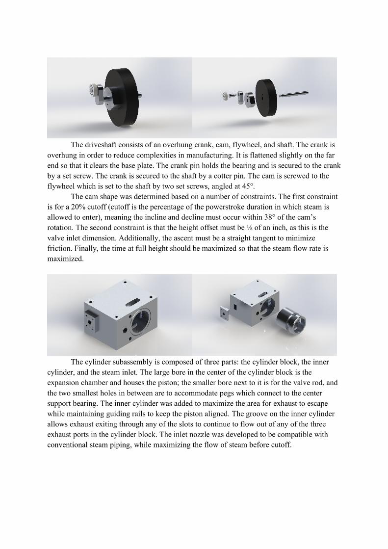
The driveshaft consists of an overhung crank, cam, flywheel, and shaft. The crank is overhung in order to reduce complexities in manufacturing. It is flattened slightly on the far end so that it clears the base plate. The crank pin holds the bearing and is secured to the crank by a set screw. The crank is secured to the shaft by a cotter pin. The cam is screwed to the flywheel which is set to the shaft by two set screws, angled at 45°. The cam shape was determined based on a number of constraints. The first constraint is for a 20% cutoff (cutoff is the percentage of the powerstroke duration in which steam is allowed to enter), meaning the incline and decline must occur within 38° of the cam’s rotation. The second constraint is that the height offset must be ⅛ of an inch, as this is the valve inlet dimension. Additionally, the ascent must be a straight tangent to minimize friction. Finally, the time at full height should be maximized so that the steam flow rate is maximized.
The cylinder subassembly is composed of three parts: the cylinder block, the inner
cylinder, and the steam inlet. The large bore in the center of the cylinder block is the expansion chamber and houses the piston; the smaller bore next to it is for the valve rod, and the two smallest holes in between are to accommodate pegs which connect to the center support bearing. The inner cylinder was added to maximize the area for exhaust to escape while maintaining guiding rails to keep the piston aligned. The groove on the inner cylinder allows exhaust exiting through any of the slots to continue to flow out of any of the three exhaust ports in the cylinder block. The inlet nozzle was developed to be compatible with conventional steam piping, while maximizing the flow of steam before cutoff.

The piston head has an extruded threaded rod which screws into the scotch yoke. The scotch yoke connection part is a single solid body which will be easy to manufacture with a CNC machine. It is relatively thick and has large fillets to account for the significant forces that this part experiences as the piston is shot back and forth at extremely high speeds.
The spool valve consists of the valve rod, cam follower wheel, and pin. The piston rod has been bored to allow steam into the expansion chamber during the powerstroke for a duration based on the cutoff timing determined by the cam shape. The follower wheel follows the path of the cam with minimal friction, and is held in place by the pin.
The center support bearing (left) is placed directly next to the overhung crank in order
to minimize the weight of the overhang. It is supported by dowel pegs which insert into the cylinder blocks on each side. Square extruded cuts have been incorporated to reduce overall weight. The second support bearing (right) is placed on the far end of the driveshaft to maximize distance between the support bearings. It is secured to the base plate by two bolts.

The base plate holds all of the other components in place. The two rectangular cuts are to allow space for the flywheel and scotch yoke which project beyond the base plate. The two slots are for the bottom exhaust ports on the cylinder blocks. The base plate is supported by two bars to allow sufficient clearance for the flywheel and scotch yoke. Files
- Master CAD - Renders