unified real time dynamic state...
TRANSCRIPT
POWER GRID CORPORATION OF INDIA LTD GURGAON
Feb’12
te A Report
Unified Real Time Dynamic State Measurement
(URTDSM)

TABLE OF CONTENTS
EXECUTIVE SUMMARY
CHAPTER-1: INTRODUCTION & SYNCHROPHASOR…………………………...…………. 1
1.1 Background....................................................................................................................... 1
1.2 Phasor & Synchrophasor Technology ............................................................................. 2
1.3 Synchrophasor Application Worldwide ............................................................................. 3
CHAPTER- 2: PHASOR MEASUREMENT IN INDIA ............................................................ 5
2.1 Phasor Measurement Practice in India. ............................................................................ 5
2.2 PMU Pilot project in Northern Region Grid ...................................................................... 6
2.3 Utiliization of PMU Data. ................................................................................................... 8
CHAPTER-3: EXISTING OPERATION TOOL IN SYSTEM OPERATION .......................... 13
3.1 Existing SCADA/EMS Operation .................................................................................... 13
3.2 Limitation in Existing SCADA/EMS. ................................................................................ 14
3.3 Communication Infrastructure ........................................................................................ 15
CHAPTER-4: WAMS FOR URTDSM.................................................................................. 17
4.1 Wide Area Monitoring System ........................................................................................ 17
4.2 Measurement process in WAMS .................................................................................... 17
4.3 Phasor Data Concentrator(PDC). ................................................................................... 20
4.4 Communication. .............................................................................................................. 20
4.5 Nodel PDC, Master Phasor Data Concentrator & Super PDC....................................... 21
4.6 Panel of Experts ............................................................................................................. 22
4.7 PMU/PDC Deplyment Plan ............................................................................................ 23
4.8 Visualization Tool ........................................................................................................... 26
4.9 Capacity Building- Training ............................................................................................. 26
CHAPTER-5: ANALYTICS FOR USE OF PMU DATA........................................................ 27
5.1 Analytics……….. ................................................................................................ 27
CHAPTER-6: METHODOLOGY OF IMPLEMENTATION & ESTIMATED COST............... 30 6.1 Methodology of Implementation...................................................................................... 30
6.2 Estimated Cost................................................................................................................ 31
CHAPTER-7: SOME BENIFITS ........................................................................................... 33 SUMMARY SEET & APPENDIX


Report on URTDSM
I
Executive Summary
BACKGROUND Spread of Indian Power System in increasing to new dimensions especially with the
synchronous interconnection NEW grid with Southern Regional Grid. In future single
grid of more than 250 GW capacity shall be operated in next 4-5 years. With the growth
of meshed network, complexities due to change in power flow direction, wide variation
in supply & demand etc. have grown manifold. Open Electricity Market has given a new
paradigm shift the way power is generated, transmitted and distributed. Further, In order
to maintain sustainability, emphasis has been given to develop renewable energy and
its integration with the grid. All these poses challenges in terms of grid security, safety
and stability under different operating conditions and has also increased the complexity
towards the monitoring and control of such large grid.
Existing SCADA/EMS has the capability to provide only steady state view of the power
system with high data flow latency. Synchrophasor measurements using PMU over
wide-area facilitate dynamic real time measurements and visualization of power system
which are useful in monitoring safety and security of the grid as well enable in taking
control/corrective actions in the new regime of grid management.
WAMS pilot project implemented in Northern Region (NR) consists of PMUs along with
GPS installed at selected 9 substations in the grid and a Phasor Data Concentrator
(PDC) and other associated equipment is placed at Northern Regional Load Despatch
Center (NRLDC). From the phasor data, load angle between different pockets of the
grid is available more accurately with updation time of order of few milliseconds and this
enhances the capability of the tools available to grid operator. The data historian
provided is collecting concentrated data from PDC and shall be useful for post event
analysis of any grid incidences. In the past data has also been utilized to observe low
frequency oscillations and checking effectiveness of SPS operations.

Report on URTDSM
II
Most programs for WAMS technology world over have three stages to implement
phasor technology. The initial stage is to collect and archive phasor and frequency data
from important locations throughout the grid using PMU to determine the topology and
operating limits. In Second stage, the data gathered along with real-time phasor and
frequency measurements to calculate grid conditions using analytical functions to make
suggestions to grid operator to keep grid stable and reliable. The third and final stage is
to do all of the above automatically without human intervention.
Recognising the need of WAMS application in Indian Power System, it is proposed to
follow the same philosophy i.e. installation of PMUs on substations at 400kV level and
above in the State & Central grids, all generating stations at 220kV level and above
HVDC terminals, important inter-regional connection points, inter-national connection
points etc., provision of PDC at all SLDCs, RLDCs and NLDC along with visualization
aids as a first phase. This shall facilitate an Unified Real-time Dynamic State
Measurements (URTDSM) towards improved system operation. In the subsequent
phases, development of software based analytic functions to be undertaken.
PROPOSED URTDSM IN INDIAN POWER SYSTEM List of PMU and PDCs to be installed at various substations in Central & State utilities
as part of URTDSM is tabulated as under:
Region Sub‐stations No of feeders PMU Nodal PDC MPDC SPDC
Main & Back‐up NLDC
ISTS STU ISTS STU ISTS STU NR 83 96 434 435 227 231 6 9 1 WR 60 76 520 415 267 216 11 4 1 ER 51 44 395 199 202 105 4 5 1 SR 60 71 348 289 183 152 6 4 1 NER 18 22 95 69 50 36 0 3 1 Total 272 309 1792 1407 929 740 27 25 5 581 3199 1669 57 2
In addition to above, Remote console at each RPC(5) , UT(3) ,Sikkim (1), NTMC(2)
,CEA(1) & NER States(4) ,Total 16 Remote consoles are proposed.

Report on URTDSM
III
Based on the availability of existing Fibre Optic(FO) communication link as well as FO
link under implementation, it is proposed that implementation may be undertaken in
two(2) phases; Phase-1 where substations with FO link would be available by 2014-15
and; Phase-2 in balance substations where separate FO link to be established. Details
are tabulated as under:
N R‐PH‐1 N R‐PH‐II PDC
S/st Feeder PMU S/st Feeders PMU Nodal PDC MPDC SPDC
UP 17 82 44 7 28 15 1 1
Rajasthan 8 42 24 17 61 35 1 1
Himachal Pradesh 0 0 0 3 6 3 0 1
Uttrakhand 1 2 1 5 16 8 0 1 Haryana 3 21 11 11 46 23 0 1 Delhi 3 18 9 4 14 7 0 1 J&K 0 0 0 1 2 1 0 1 Punjab 3 22 11 7 38 19 0 1 BBMB 6 37 20 0 0 0 4 1 CS 74 394 206 9 40 21 1 Total 115 618 326 64 251 132 6 9 1
SR‐PH‐I SR‐PH‐II PDC
S/St Feeders PMU S/St Feeders PMU Nodal PDC MPDC SPDC
Andhra Pradesh 10 61 32 18 60 32 2 1 Karnataka 1 8 4 18 65 33 0 1 Tamilnadu 3 14 7 13 49 27 0 1 Kerala 2 7 4 6 25 13 0 1 Central 57 338 178 3 10 5 4 1 TOTAL 73 428 225 58 209 110 6 4 1
WR‐PH‐I WR‐PH‐II PDC
S/ST Feeders PMU S/ST Feeders PMU Nodal PDC MPDC SPDC
MAHARASTRA 4 34 18 26 128 65 2 1 MADHYA PRADESH 8 57 30 6 30 16 1 1
Report on URTDSM
IV
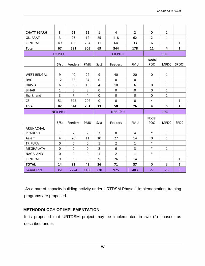
CHATTISGARH 3 21 11 1 4 2 0 1 GUJARAT 3 23 12 25 118 62 2 1 CENTRAL 49 456 234 11 64 33 6 1 Total 67 591 305 69 344 178 11 4 1
ER‐PH‐I ER‐PH‐II PDC
S/st Feeders PMU S/st Feeders PMU Nodal PDC MPDC SPDC
WEST BENGAL 9 40 22 9 40 20 0 1 DVC 12 66 34 0 0 0 1 ORISSA 6 30 16 4 10 6 0 1 BIHAR 1 6 3 0 0 0 0 1 Jharkhand 3 7 4 0 0 0 0 1 CS 51 395 202 0 0 0 4 1 Total 82 544 281 13 50 26 4 5 1
NER‐PH‐I NER‐Ph‐II PDC
S/St Feeders PMU S/st Feeders PMU Nodal PDC MPDC SPDC
ARUNACHAL PRADESH 1 4 2 3 8 4 * 1 Assam 4 20 11 10 27 14 0 1 TRIPURA 0 0 0 1 2 1 * MEGHALAYA 0 0 0 2 6 3 * 1 NAGALAND 0 0 0 1 2 1 * CENTRAL 9 69 36 9 26 14 1 TOTAL 14 93 49 26 71 37 0 3 1 Grand Total 351 2274 1186 230 925 483 27 25 5
As a part of capacity building activity under URTDSM Phase-1 implementation, training
programs are proposed.
METHODOLOGY OF IMPLEMENTATION
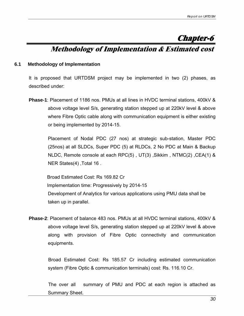
It is proposed that URTDSM project may be implemented in two (2) phases, as
described under:

Report on URTDSM
V
Phase-1: Placement of 1186 nos. PMUs at all lines in HVDC terminal stations, 400kV &
above voltage level S/s, generating station stepped up at 220kV level & above
where Fibre Optic(FO) cable along with communication equipment is either
existing or being implemented by 2014-15.
Placement of Nodal PDC (27 nos) at strategic sub-station, Master PDC
(25nos) at SLDCs, Super PDC (5) at RLDCs, 2 No PDC at Main & Backup
NLDC, Remote console at each RPC(5) , UT(3) ,Sikkim , NTMC(2),CEA(1) &
NER States(4) ,Total 16 .
Broad Estimated Cost: Rs 169.82 Cr
Implementation time: Progressively by 2014-15
Development of Analytics for various applications using PMU data shall be
taken up in parallel.
Phase-2: Placement of balance 483 nos. PMUs at all HVDC terminal stations, 400kV &
above voltage level S/s, generating station stepped up at 220kV level & above
along with provision of Fibre Optic connectivity and communication
equipments.
Broad Estimated Cost: Rs 185.57 Cr including estimated communication
system (Fibre Optic & communication terminals) cost: Rs. 116.10 Cr.
• Estimated cost of URTDSM Phase-1 for WAMS: Rs. 169.82 Cr.
• Estimated cost of URTDSM Phase-2 for WAMS: Rs. 69.47 Cr.
Total cost of WAMS (Ph-1 & 2) : Rs. 239.29 Cr.
• Estimated cost of communication system under Phase-2: Rs. 116.10 Cr

Report on URTDSM
VI

Report on URTDSM
Chapter-1 Introduction & Synchrophasor
1.1 BACKGROUND Indian power system is spreading at a fast pace to meet the growing requirement. In
order to facilitate optimal utilization of unevenly distributed energy resources,
strengthening of regional grids through inter-State/regional system is taking place
continuously. Out of the five(5) regional grids, four(4) grids viz Northern, Western,
Eastern and North-Eastern regions with capacity of about 137 GW have been
synchronized with one another while the remaining Southern grid (49 GW) is
expected to be synchronized by 2014.
Widely spreading grid has also increased the complexity towards monitoring and
control of such large grid. Significant quantum of power exchange among the regions
triggered by Short-term Open Access, at times leads to congestion in certain
corridors. Factors like seasonal loads, effects of weather and critical events also led
to complex operating scenarios like fast changing power flow patterns coupled with
significant loading upto emergency level etc. As per Indian electricity grid code each
State/DISCOM is responsible for maintaining its load generation balance. Frequency
is allowed to vary under specified band. Flexibility in frequency led to over drawal,
under drawal, over generation and under generation by the utilities leading to over
loading of lines and rise and dip of voltages in the grid. The excessive penetration of
renewable generation due its unpredictability, variability and intermittency will also
pose challenges in operation of the grid. Under such complexities, carrying out
security assessment on real time basis and responding to contingencies are critical
for maintaining reliability and stability of the grid.
Recent advances in measurement, communications and analytic technologies have
produced a range of new options. In particular, wide area measurement systems
(WAMS) have come to the fore as a means to address not just immediate reliability
concerns but also operations issues like enhancing transfer capability in real time,
advanced automatic corrective actions like adaptive islanding, blocking/de-blocking
1
Report on URTDSM
of distance relay zones under power swings, better visualization through state
measurements, decision support tools etc.
The existing SCADA/EMS provides only the steady state view of the power system.
These systems take a minute to deliver a snap shot of a system whose characterstic
are changing very fast. In contrast to the conventional SCADA system where RTUs
are used to acquire voltage, current and frequency, Wide Area Monitoring system
acquire current, voltage (both magnitude and phase angle) and frequency
measurement by phasor measurement and are also time synchronised via Global
Positioning System (GPS) receiver to a time resolution of 1 micro sec. so that Real
Time Dynamic State Measurements/Monitoring of System across the widely spread
grid is possible. The wide area measurement facilitates better, faster analyses of grid
conditions, which in turn provide operators with more time and more options to
preserve system stability. It also represents a quantum leap in the quality of data on
which everyday operational decisions are based. This will help in maintaining grid
safety and security and will be a step towards intelligent and self healing grid.
Deployment of this technology in Indian Power System has been envisaged in the
Report of Working Group on Power for 11th Plan, Government of India as well as in
National Electricity Policy.
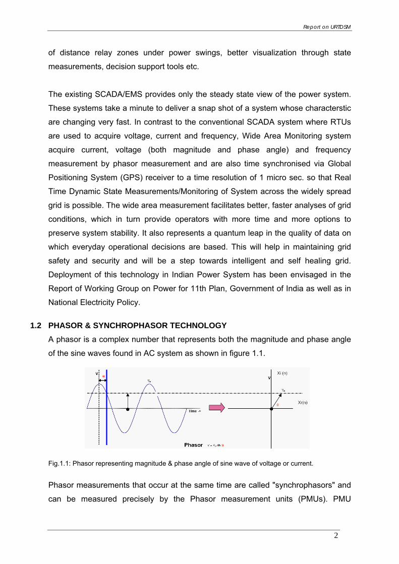
1.2 PHASOR & SYNCHROPHASOR TECHNOLOGY A phasor is a complex number that represents both the magnitude and phase angle
of the sine waves found in AC system as shown in figure 1.1.
Fig.1.1: Phasor representing magnitude & phase angle of sine wave of voltage or current.
Phasor measurements that occur at the same time are called "synchrophasors" and
can be measured precisely by the Phasor measurement units (PMUs). PMU
2
Report on URTDSM
measurements are taken at high speed typically 25 or 50 samples per second –
compared to one every 4 to 10 seconds using conventional technology. Each
measurement is time-stamped according to a common time reference. Time
stamping allows phasors at different locations to be time-aligned (or synchronized)
thus providing a comprehensive view of the entire grid at central location. A typical PMU installation as a part of wide area monitoring system (WAMS) network
consists of phasor measurement units (PMUs) dispersly placed throughout the
electricity grid at strategic locations in order to cover the diverse footprint of the grid.
A Phasor Data Concentrator (PDC) at central location collects the information from
PMUs and provides alert and alarm for emergency situations as well as facilitates
development of different types of analytics for smooth operation of grid on real time
basis. The PMU data is also transmit to Supervisory Control and Data Acquisition
(SCADA) system after time aligning the same. The WAMS technology requires high
bandwidth communication network for rapid data transfer matching the frequency of
sampling of the PMU data.
1.3 SYNCHROPHASOR APPLICATION WORLDWIDE
Worldwide many utilities from North America, Europe, China, Russia and Brazil have
started using/developing the new PMU applications to harness the potential benefits
of this emerging technology in operating very large electrical grids.
In 2006, China's Wide Area Monitoring Systems (WAMS) for its six(6) grids had 300
PMUs installed mainly at 500kV and 330kV substations and power plants. Presently
China has installed more than 1000 PMUs in their Grid. By 2012, China plans to
have PMUs at all 500kV substations and all power plants of 300MW and above
In U.S there are ten(10) synchrophasor projects underway involving 57 utilities and
grid operators across the country and installing about 850 networked PMUs. By
2013, the devices will be operating in nearly all regions of the country. The Eastern
Interconnect Phasor Project (EIPP) (now known as the North American
Synchrophasor Initiative, or NASPI), has over 40 connected phasor measurement
units collecting data into a "Super Phasor Data Concentrator" system centered at
Tennessee Valley Authority (TVA). Southern California Edison is successfully using
3

Report on URTDSM
synchrophasors today to trigger some automated grid protection functions on their
system
Oklahoma Gas & Electric Co.(OG&E), USA uses synchrophasor technology as a
practical tool to locate and solve real-world operating problems. The utility has added
more than 100 PMUs to the system, which provided monitoring almost 30% of its
transmission grid. From the synchrophasor data, OG&E can determine if a
disturbance is cleared by high-speed or step-distance (delayed) tripping. The data is
being used to locate the source of event disturbance and proceed with an
investigation. Another valuable use of synchrophasor data is the detection of
equipment failure, most of which is not detectable by SCADA system. System
stability assessment is being carried out using synchrophasor data especially
capturing the intricacies of an interconnected system like low frequency oscillations
due to generation control problem or other reasons. The benefit of PMU
measurements at the point of wind farm interconnection facilitates customer to
receive clean power (in terms of voltage fluctuation/flicker) while maintaining the
level of system stability necessary for reliable power system operation.
Apart from above nations, other countries like South Africa, Brazil, USSR, Western
Electricity Coordinating Council (WECC) whose service territory extends from
Canada to Mexico and some European countries have deployed/ planning to deploy
a large no. of PMUs in their system.
4

Report on URTDSM
Chapter-2 Phasor Measurement in India
2.1 PHASOR MEASUREMENT PRACTICE IN INDIA
National and Regional Load Despatch Centres in India are being operated by Power
Systems Operation Corporation(POSOCO), a wholly owned subsidiary of
POWERGRID, whereas State Load DespatchCentres are operated by respective
State utilities. They are equipped with State-of-the-Art SCADA/EMS system.
Telemetry from different sub-stations and power plants are being received at each
SLDC/RLDC and subsequently to NLDC which are being utilized in day to day
operations of the regional grid.
Synchronous Interconnection of regional grids forming large interconnected system
(for example formation of NEW grid ) and various changes undergoing in the Indian
power industry requires better situational awareness of the grid event and
visualization at the control center for real time system operation. Knowledge about
the angular separation between different nodes of a power system has always been
of great interest for power system operators. Phase angle measurement is
commonly used in auto synchronization of generating stations and check
synchronization relays used at substations for closing of lines as well as during
three-phase auto-reclosing. All these applications are at the local level.
Prior to the introduction of Phasor Measurement Units (PMUs) at control centre level
this analogue value is normally not considered as measurable in SCADA system and
hence does not form a part of the SCADA measurement. However SCADA
technology does provide an estimate of the relative phase angle difference (with
respect to a reference bus) through the State Estimator. The State estimator uses
the SCADA inputs (analogue and digital measurands) to estimate the system state
viz. node voltage and angle.
Information about phase angle difference between two different nodes in a power
system has also been calculated based on the real time power flow between the
5

Report on URTDSM
nodes, bus voltages and network reactance using standard equation δ = sin-1
(P*X/V1*V2). Angular information at control centre is also obtained by placing phase
angle transducer at strategic locations and interfacing it in existing SCADA system
However all the above methods of calculation of phase angle difference have
limitations due to resolution, data latency, updation time and data skewedness.
Update time in the SCADA system is considerably large (up to 10-15 seconds) for
visualizing and controlling the dynamics of power system. The real time angular
measurement in the power system avoids above uncertainties and can be relied on
to assess the transmission capability in real time which is very crucial in efficiently
operating the present electricity market mechanism.
PMUs are able to measure what was once immeasurable: phase difference at
different substations. A pilot project was implemented in Northern Region (NR) to
assess the potential of PMU/synchrophasor measurements. Experienced gained
with this pilot project is described in the following paragraph.
2.2 PMU PILOT PROJECT IN NORTHERN REGION GRID The PMU pilot project implemented in NR consists of PMUs along with GPS installed
at selected 9 substations in the grid(Refer Fig-2.1). A Phasor Data Concentrator and
other associated equipment are placed at Northern Regional Load Despatch Centre
(NRLDC) located at New Delhi as shown in Fig 2.2.
Fig 2.1: Locations of PMUs in the NR
Fig 2.2: Hardware Architecture of PMU Pilot Project
6

Report on URTDSM
7
PMUs have been installed at Vindhychal HVDC, Dadri HVDC, 400kV S/s at Kanpur,
Moga, Agra, Hisar, Kishenpur, Bassi and KarchamWangtoo. PMUs are presently taking
voltage & current inputs. Voltage inputs have been provided from CVT/PT of the main
bus of the substation. PDC and associated equipments installed at NRLDC is shown in
Fig 2.3. PMU along with GPS as installed at one of the location are shown in Fig 2.4.
Phasor data at each PMU is being sampled at 25 samples per second with GPS time
stamping and transferred to Phasor Data Concentrator (PDC) provided at NRLDC
through dedicated 64kbps fiber optic communication link. The phasor data received
from all the locations is merged and time aligned in the PDC. The time aligned data
from PDC is provided to operator console for visualization.
The visualization display on an operator console is shown in Fig 2.5 to 2.8. PDC data is
also fed to a data historian provided at NRLDC. Data from historian can be made
available to external database through ODBC (Open Database Connectivity) and
spreadsheet for further analysis. PDC has also been provided with OPC (OLE for
Process Control) server in order to transfer real time phasor data to existing SCADA
system. Communication between PMUs at remote locations and PDC at central location
takes place as per IEEE C37.118 standard.
Fig 2. 3: PDC and other Equipments at Fig 2. 4: PMU and GPS at Substation NRLDC

Report on URTDSM
8
Fig 2.5 Fig-2.6
Fig 2.7 Fig 2.8
2.3 UTILIZATION OF PMU DATA
The data from synchrophasor is a huge leap from the data from SCADA system. An
accurate measurement of voltage and current phasors for four locations in the grid is
now available with a resolution of 40 ms i.e, 25 samples per second. The precise
relative phase angle separation can also be seen. Apart from these angular separation
other important system monitoring parameters such as frequency, rate of change of
frequency, positive sequence phase voltages and power flow are also available. Even
the limited exposure with synchrophasor data has been a revelation in terms of its
Report on URTDSM
9
potential for future applications. The data is being examined closely for drawing
inferences. Some of the inferences are as under:
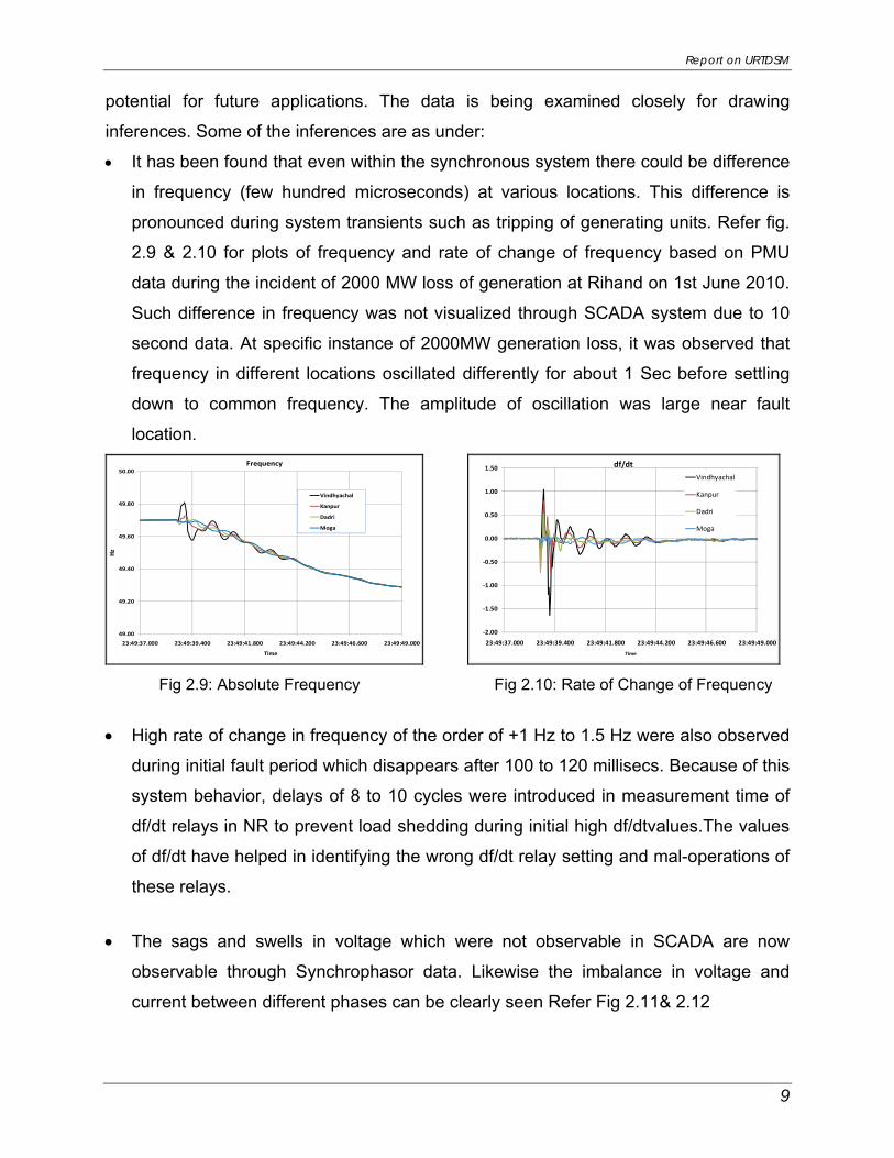
• It has been found that even within the synchronous system there could be difference
in frequency (few hundred microseconds) at various locations. This difference is
pronounced during system transients such as tripping of generating units. Refer fig.
2.9 & 2.10 for plots of frequency and rate of change of frequency based on PMU
data during the incident of 2000 MW loss of generation at Rihand on 1st June 2010.
Such difference in frequency was not visualized through SCADA system due to 10
second data. At specific instance of 2000MW generation loss, it was observed that
frequency in different locations oscillated differently for about 1 Sec before settling
down to common frequency. The amplitude of oscillation was large near fault
location.
49.00
49.20
49.40
49.60
49.80
50.00
23:49:37.000 23:49:39.400 23:49:41.800 23:49:44.200 23:49:46.600 23:49:49.000
Hz
Time
Frequency
Vindhyachal
Kanpur
Dadri
Moga
‐2.00
‐1.50
‐1.00
‐0.50
0.00
0.50
1.00
1.50
23:49:37.000 23:49:39.400 23:49:41.800 23:49:44.200 23:49:46.600 23:49:49.000Time
df/dt Vindhyachal
Kanpur
Dadri
Moga
Fig 2.9: Absolute Frequency Fig 2.10: Rate of Change of Frequency
• High rate of change in frequency of the order of +1 Hz to 1.5 Hz were also observed
during initial fault period which disappears after 100 to 120 millisecs. Because of this
system behavior, delays of 8 to 10 cycles were introduced in measurement time of
df/dt relays in NR to prevent load shedding during initial high df/dtvalues.The values
of df/dt have helped in identifying the wrong df/dt relay setting and mal-operations of
these relays.
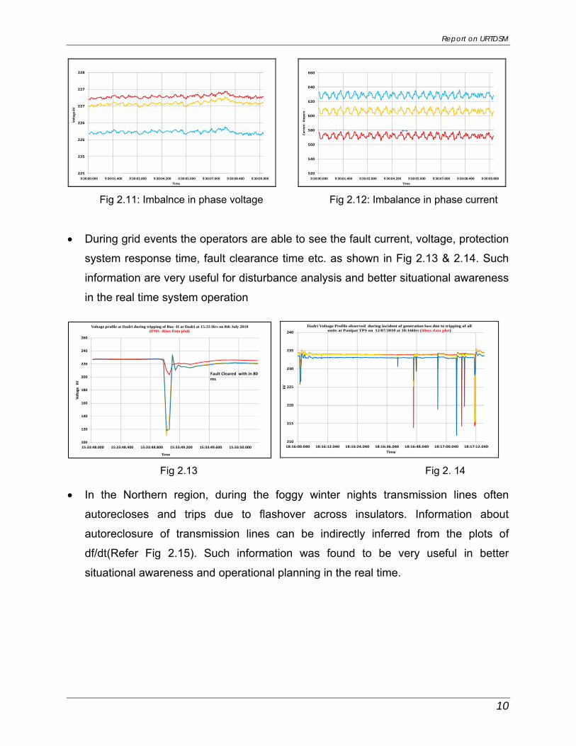
• The sags and swells in voltage which were not observable in SCADA are now
observable through Synchrophasor data. Likewise the imbalance in voltage and
current between different phases can be clearly seen Refer Fig 2.11& 2.12
Report on URTDSM
10
225
225
226
226
227
227
228
9:30:00.000 9:30:01.400 9:30:02.800 9:30:04.200 9:30:05.600 9:30:07.000 9:30:08.400 9:30:09.800
Volta
ge‐kV
Thou
sand
s
Time 520
540
560
580
600
620
640
660
9:30:00.000 9:30:01.400 9:30:02.800 9:30:04.200 9:30:05.600 9:30:07.000 9:30:08.400 9:30:09.800
Curren
t ‐Am
pere
Time Fig 2.11: Imbalnce in phase voltage Fig 2.12: Imbalance in phase current • During grid events the operators are able to see the fault current, voltage, protection
system response time, fault clearance time etc. as shown in Fig 2.13 & 2.14. Such
information are very useful for disturbance analysis and better situational awareness
in the real time system operation
210
215
220
225
230
235
240
18:16:00.040 18:16:12.040 18:16:24.040 18:16:36.040 18:16:48.040 18:17:00.040 18:17:12.040
kVTh
ousand
s
Time
Dadri Voltage Profile observed during incident of generation loss due to tripping of all units at Panipat TPS on 12/07/2010 at 18:16Hrs (40ms data plot)
Fig 2.13 Fig 2. 14
100
120
140
160
180
200
220
240
260
15:33:48.000 15:33:48.400 15:33:48.800 15:33:49.200 15:33:49.600 15:33:50.000
Volta
ge k
VTh
ousand
s
Time
Voltage profile at Dadri during tripping of Bus -II at Dadri at 15:33 Hrs on 8th July 2010 (PMU 40ms Data plot)
Fault Cleared with in 80 ms
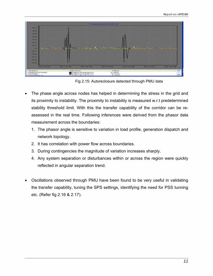
• In the Northern region, during the foggy winter nights transmission lines often
autorecloses and trips due to flashover across insulators. Information about
autoreclosure of transmission lines can be indirectly inferred from the plots of
df/dt(Refer Fig 2.15). Such information was found to be very useful in better
situational awareness and operational planning in the real time.
Report on URTDSM
11
Fig 2.15: Autoreclosure detected through PMU data
• The phase angle across nodes has helped in determining the stress in the grid and
its proximity to instability. The proximity to instability is measured w.r.t predetermined
stability threshold limit. With this the transfer capability of the corridor can be re-
assessed in the real time. Following inferences were derived from the phasor data
measurement across the boundaries:
1. The phasor angle is sensitive to variation in load profile, generation dispatch and
network topology.
2. It has correlation with power flow across boundaries.
3. During contingencies the magnitude of variation increases sharply.
4. Any system separation or disturbances within or across the region were quickly
reflected in angular separation trend.
• Oscillations observed through PMU have been found to be very useful in validating
the transfer capability, tuning the SPS settings, identifying the need for PSS tunning
etc. (Refer fig 2.16 & 2.17).

Report on URTDSM
12
49.90
49.92
49.94
49.96
49.98
50.00
50.02
50.04
50.06
50.08
50.10
50.12
4:28:53.000 4:28:57.000 4:29:01.000 4:29:05.000 4:29:09.000 4:29:13.000 4:29:17.000
Hz
Time
Frequency profile on 16th July 2011 from 04:28 ‐ 04:31 Hrs (40ms data plot)
4:29:07.5604:28:57.240
DADRI.FREQ MOGA.FREQ HISSAR.FREQ
Fig 2.16 Fig 2.17 • Delay in operating time of SPS for reliable evacuation of additional 2x250 MW
generation in the Baspa Hydro, Jhakri Hydro and KarchamWangtoo Hydro complex
could be detected only through the PMU measurements available at NRLDC that
was suitably corrected.
• Oscillations observed through PMU in the entire NEW grid system, during high
loading of 400 kV Tehri-Merrut line, when one of this D/C line was out for
construction of Koteshwar evacuation facilitated the need for proper tuning of PSS
at Tehri end to avoid in major disturbances / damage to generators.
• Information obtained through PMUs has been found to be very helpful in monitoring
the performance of protection system in the grid. Some of the discrepancies in
overvoltage settings and unnecessary overvoltage tripping could be detected
through the PMU, those were later rectified.
• PMU measurement has also been found to be very useful in validating the real time
online SCADA network model and offline network models

Report on URTDSM
13
Chapter-3 Existing Operation Tool in System Operation
3.1 EXISTING SCADA/EMS OPERATION
The Supervisory Control and Data Acquisition (SCADA)/Energy Management Systems
(EMS) are based on distributed architecture incorporating open system features. The
communication system consisting of Fiber Optic and Microwave provide faster and
reliable data transfer and voice communication between Control Centers.
SCADA/EMS system is hierarchical in nature having four levels of hierarchies. At
national level, SCADA/EMS systems of all five (5) RLDCs report to NLDC. Data from
each RLDC is transmitted to NLDC in real time on dedicated communication lines. At
regional level, RLDC coordinates all the inter-state activities of SCADA/EMS systems of
SLDCs of a region. SCADA systems of all the Sub-LDCs of a state report to the SLDC
of that state. The hierarchy of grid management is shown in Fig. 3.1
Fig 3.1: Hierarchy in Grid Operation management
Main components of the SCADA system at RLDC and SLDC are SCADA/EMS server
and ICCP server. SCADA/EMS or data server maintain all data acquired from other

Report on URTDSM
14
SLDCs etc and make it available to display and reporting. ICCP (Inter Control-center
Communication Protocol) server acts as gateway for transfer of data between SLDCs
and between RLDC and SLDCs. SCADA/EMS system at RLDC, SLDC and Sub-LDC
are based on distributed architecture and open standards. The major functions of the
SCADA/EMS system are summarized below:-
SCADA Functions • Data acquisition from RTUs
• Supervisory control of power system element (not being used at present)
• Historical data storage and retrieval
• Sequence of events recording
EMS Functions
• Operation Monitoring
• Operation Scheduling-Load Forecasting, Hydro Scheduling, Interchange
Scheduling
• Network Analysis - State Estimation, Bus Load Forecast, Contingency Analysis,
Optimum Power Flow
3.2 LIMITATION IN EXISTING SCADA/EMS
In existing SCADA/EMS the field data is obtained from RTUs. As the RTUs are
scattered in large geographical Area, the data from a cluster of RTUs are concentrated
at Sub-LDC level and sent to SLDC and then to RLDC by wide band communication as
shown in the Fig 3.2. Thus the data updation time at the main control centre is having a
latency of few seconds ranging from 10 to 30 seconds. Based on this updation, the
state of the power system is estimated using state estimator every few minutes or on
operators demand. But this estimation has its own limitations because data from
different locations has time skewed as the data is not time synchronized. Some of the
data is reported directly by RTU and some is updated through ICCP. Even the data
coming from different RTU/ICCP comes in different scan group and through different
channels of communication (Fibre Optic, Digital Microwave, PLCC). Thus at times the
estimate does not converge due to time skew in measured values or wrong parameter
or telemetry failure and in even when it converges the accuracy is low.. Due to slow rate

Report on URTDSM
15
of data update at times, the fluctuations are observed in the network through SCADA
system due to fault/power swing/ loss of generation/load but the operators find it difficult
to accurately pin point the cause and location of problems.
Fig 3.2: Data flow time in SCADA
Data Flow Latency
3.3 COMMUNICATION INFRASTRUCTURE The communication network built under ULDC (Unified Load Desptch &
Communication) project consists of Fiber Optic, Digital Microwave (DMW) and PLCC
based Communication System. In August, 2008, DoT intimated that 2.3 to 2.4 GHz
frequency band presently being used for microwave communication will be allocated for
Broadband Wireless Access (BWA.) services as per GOI guidelines. Hence, the users
of 2.3 – 2.4 GHz band are required to vacate the band. Accordingly, establishment of
Fibre Optic networks under Microwave replacement projects have been undertaken for
NR, SR, ER & NER and approved by respective RPCs which is under implementation.
In addition, Fibre Optic links are being implemented under expansion projects for WR,
NR, ER & SR.
RTU RTU RTURTU RTU RTU
SUB LDC SUB LDC SUB LDCSUB LDC SUB LDC SUB LDC
SLDC SLDC SLDCSLDC SLDC SLDC
ERLDC WRLDC NRLDC SRLDC NERLDC
20
15
1 Plant/Sub Station Level
Group of Distt. Level
State HQ Level
Region Level
National Level
25
NLDCNLDC
12-15 seconds 12-15 seconds
12-15 seconds
12-15 secs
12-15 seconds
RTU RTU
SKEWIn sec
30
2 seconds
2 seconds
2 seconds
Report on URTDSM
16
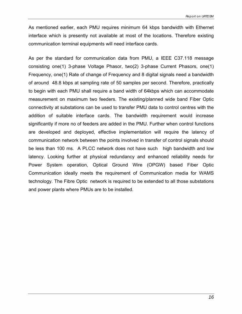
As mentioned earlier, each PMU requires minimum 64 kbps bandwidth with Ethernet
interface which is presently not available at most of the locations. Therefore existing
communication terminal equipments will need interface cards.
As per the standard for communication data from PMU, a IEEE C37.118 message
consisting one(1) 3-phase Voltage Phasor, two(2) 3-phase Current Phasors, one(1)
Frequency, one(1) Rate of change of Frequency and 8 digital signals need a bandwidth
of around 48.8 kbps at sampling rate of 50 samples per second. Therefore, practically
to begin with each PMU shall require a band width of 64kbps which can accommodate
measurement on maximum two feeders. The existing/planned wide band Fiber Optic
connectivity at substations can be used to transfer PMU data to control centres with the
addition of suitable interface cards. The bandwidth requirement would increase
significantly if more no of feeders are added in the PMU. Further when control functions
are developed and deployed, effective implementation will require the latency of
communication network between the points involved in transfer of control signals should
be less than 100 ms. A PLCC network does not have such high bandwidth and low
latency. Looking further at physical redundancy and enhanced reliability needs for
Power System operation, Optical Ground Wire (OPGW) based Fiber Optic
Communication ideally meets the requirement of Communication media for WAMS
technology. The Fibre Optic network is required to be extended to all those substations
and power plants where PMUs are to be installed.

Report on URTDSM
17
Chapter-4 WAMS for URTDSM
4.1 WIDE AREA MONITORING SYSTEM (WAMS)
A WAMS (Wide Area Monitoring Systems) using Phasor measurement unit (PMUs) is
advanced measurement system that provides synchronized measurements at subsec
rate. The WAMS technology provides phasor measurements in terms of amplitude and
phase angle of voltage and current over a widely spread grid.
The components of WAMS consists of Phasor Measurement Units (PMUs), Phasor
Data Concentrators (PDCs), Visualization aids, Application and Analysis modules, Data
archiving and storage etc. The basic infrastructure of WAMS technology is PMU, wide-
band communication and PDC units.
4.2 MEASUREMENT PROCESS IN WAMS
Bus voltage and current phasors in transmission line is measured directly through PMU
in terms of amplitude as well as phase angle. Input to the PMU is taken from bus PT
and line CT at the substation including time signal through GPS. Phase angle is
measured relative with GPS frame. The standard PMU presently available in market is
capable of taking two sets of three phases current, one set of three phase voltage and 8
digital inputs. Thus, current signals from any 2 feeders can be connected to one
PMU.Based on this number of PMUS in a station is calculated. Output from PMUs in a
particular station (sending station) is transmitted through a LAN switch and router to
PDC.
A Phasor Data Concentrator (PDC) is used to collect data from multiple PMUs and
other PDCs. A PDC also aligns data by time tag to create a time synchronized dataset,
and transmit this dataset to other information system. All data concentrators are
connected locally to the respective host computer, printers and operators console via
Ethernet. PDCs can also filter the data so that it can be fed to applications which use
slow sample data such as SCADA system. The PDC is capable of correlating the time
Report on URTDSM
18
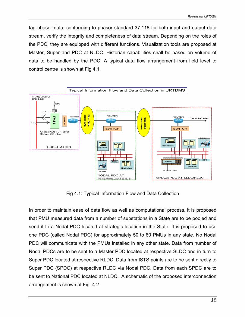
tag phasor data; conforming to phasor standard 37.118 for both input and output data
stream, verify the integrity and completeness of data stream. Depending on the roles of
the PDC, they are equipped with different functions. Visualization tools are proposed at
Master, Super and PDC at NLDC. Historian capabilities shall be based on volume of
data to be handled by the PDC. A typical data flow arrangement from field level to
control centre is shown at Fig 4.1.
Fibre Optic
based WAN
SWITC
HPT
CT
PM
U
TRANSMISSION ONE LINE
PrinterWorkstation
Firewall
PDC
Historian
GPS
SCADA LAN
ROUTERROUTER ROUTER
Printer
Workstation
Nodal PDC
Historian
GPS
Printer
GPS
Typical Information Flow and Data Collection in URTDMS
Analog:V,Φ,I , f , df/dtStatus: CB , Iso
To NLDC PDC
SWITCH
NODAL PDC AT INTERMEDIATE S/S
SWITCH
MPDC/SPDC AT SLDC/RLDC
Fibre Optic
based WAN
SUB-STATION
Fig 4.1: Typical Information Flow and Data Collection
In order to maintain ease of data flow as well as computational process, it is proposed
that PMU measured data from a number of substations in a State are to be pooled and
send it to a Nodal PDC located at strategic location in the State. It is proposed to use
one PDC (called Nodal PDC) for approximately 50 to 60 PMUs in any state. No Nodal
PDC will communicate with the PMUs installed in any other state. Data from number of
Nodal PDCs are to be sent to a Master PDC located at respective SLDC and in turn to
Super PDC located at respective RLDC. Data from ISTS points are to be sent directly to
Super PDC (SPDC) at respective RLDC via Nodal PDC. Data from each SPDC are to
be sent to National PDC located at NLDC. A schematic of the proposed interconnection
arrangement is shown at Fig. 4.2.

Report on URTDSM
19
Super PDC at RLDCs
PDC at Back up NLDC PDC at NLDC
Master PDC at SLDCs
Remote Console at RPCs
State Stns
PMU1
PMUn
Router/switch
Sub Stn 1
UNIFIED REAL TIME DYNAMIC STATE MEASUREMENT SYSTEM HIERARCHY
Nodal PDC at sub-stationNodal PDC at sub-station
State Stns
PMU1
PMUn
Router/switch
Sub Stn A
State Stns
PMU1
PMUn
Router/switch
Sub Stn m
Centre Stns
PMU1
PMUn
Router/switch
Sub Stn B
Remote Consoleat UT(3) & NER States(4),
Sikkim ,NTMC(2),CEA
Fig 4.2: Hierarchy of Unified Real Time Dynamic Measurement System
Most programs for WAMS technology world over have three (3) stages of
implementation. The first stage is to install PMU, PDC and collect/archive phasor data
from important locations throughout the grid to determine the topology and operating
limits. In Second stage, the data gathered along with real-time phasor and frequency
measurements to calculate grid conditions using analytical functions to make
suggestions to grid operator to keep grid stable and reliable. The final stage is to carry
out all of the above functions automatically.
In Indian Power System context, it is proposed to follow the similar philosophy i.e.
installation of PMUs on substations at 400kV level and above in the State & Central
grids, all generating stations at 220kV level and above, HVDC terminals, important inter-
regional/national connection points etc., provision of PDC at strategic sub-stations to
collect the data of nearby PMUs, all SLDCs, RLDCs and NLDC along with visualization
aids as a first phase. This shall facilitate a Unified Real-time Dynamic State Measurements (URTDSM) tool towards improved system operation. In the subsequent
phases, development of software based analytic functions and automatic corrective
actions will be undertaken.

Report on URTDSM
20
4.3 PHASOR DATA CONCENTRATOR (PDC)
The electrical parameters measured by a number of PMUs are to be collected by some
device either locally or remotely, this function is performed by Phasor Data Concentrator
(PDC). A PDC forms a node in a system where phasor data from a number of PMUs is
collected, correlated and fed as a single stream to other applications. In a hierarical set
up the PDCs can also be used to collect the data from number of down stream PDCs.
PDC provides additional functions as under:
• It performs quality checks on the phasor data and inserts appropriate flags
• It checks disturbance flags and records files of data for analysis
• It monitors the overall measurement system and provides a display and record of
performance
• It can provide a number of specialized outputs that can be interfaced with the other
system e.g SCADA/EMS system.
4.4 COMMUNICATION The Communication infrastructure is critical backbone in the architecture of a WAMS
system. PMU devices are distributed over a wide area, covering various locations within
the boundary of a power system. The PMU devices are then connected to one or many
control centers over the communication network. Fibre Optic Communication network
due to its high bandwidth offer low latency for communication between PMU to PDC
and PDC to PDC. The Fibre Optic terminal equipments will have the provision of in-built
Ethernet port. The Ethernet port shall be used in the communication network of WAMS
for dedicated channels.. The existing SDH equipment will have Ethernet converter for
converting from E-1 to Ethernet.
The network architecture would then be composed of a main optical fibre backbone
connected to the substation Router/Switch. In turn, the PMU can be connected to the
substation through Switch and Switch. The PMU measurements are then transferred to
a PDC, which time aligns the phasors. Block diagram of communication architecture
between PMUs at the locations in substations and information exchange at the
substation control room is shown at Fig 4.3.

Report on URTDSM
21
Router
Sub Station Control Room
2 No Bays
2 No Bays
2 No Bays
GPS Receiver
PMU
GPS Receiver
Switch
PMUCT/PT
GPS Receiver
PMUCT/PTCT/PT
IEEE C 37.118
Switchyard Area
Fig. 4.3: Communication architecture between Substation PMUs & Control centre
4.5 Nodal PDC, Master Phasor Data Concentrator (MPDC) & Super PDC A nodal PDC shall be located at strategic location in Central and State Sector to pool
the data of PMUs installed in various sub-stations of that area. Approximately for 50 to
60 PMUs one nodal PDC is planned. Nodal PDC is equipped with Historian for data
storage. Master PDC will collect and correlate the required data from PMUs and Nodal
PDCs under its area of operation. The Master PDC shall be located at the SLDC
Control Center. It is proposed to have an analytical tool and visualization software
package for all Master PDC. The Master PDC will also be connected to a central
database for long-term archiving of the collected data for post disturbance analysis.
Super PDCs are to be placed at each RLDC which will collect data from PMUs at ISTS
stations and ISGS as well as from MPDC. The PDC at NLDC will collect information
from all the five (5) Super PDCs at RLDCs. Remote console is proposed at each RPC
and NTAMC for carrying out analysis/studies. The proposed WAMS architecture for
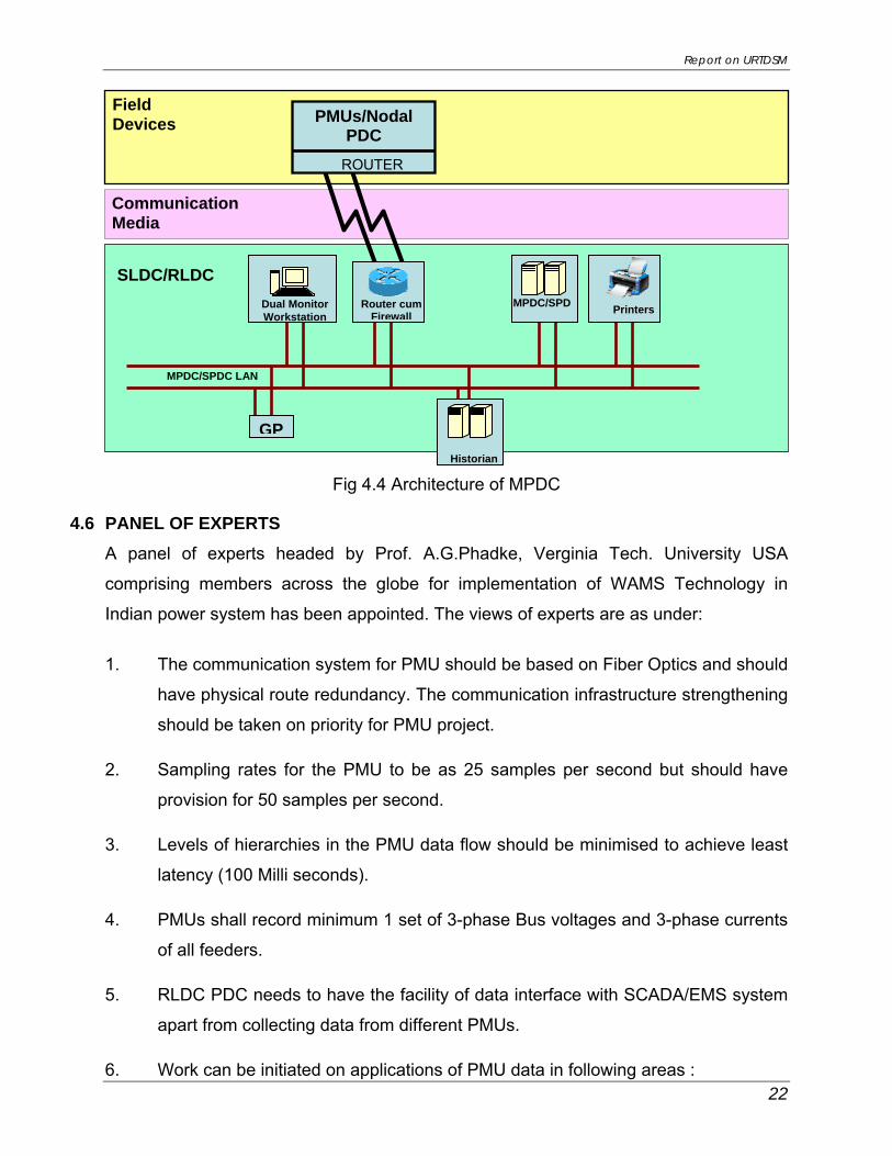
Unified Real Time Dynamic State Measurements (URTDSM) is shown at Fig. 4.4
Report on URTDSM
22
Communication Media
Field Devices
Dual Monitor Workstation
GPHistorian
Router cum Firewall
PMUs/Nodal PDC
MPDC/SPDC LAN
SLDC/RLDC
ROUTER
MPDC/SPD Printers
Fig 4.4 Architecture of MPDC
4.6 PANEL OF EXPERTS A panel of experts headed by Prof. A.G.Phadke, Verginia Tech. University USA
comprising members across the globe for implementation of WAMS Technology in
Indian power system has been appointed. The views of experts are as under:
1. The communication system for PMU should be based on Fiber Optics and should
have physical route redundancy. The communication infrastructure strengthening
should be taken on priority for PMU project.
2. Sampling rates for the PMU to be as 25 samples per second but should have
provision for 50 samples per second.
3. Levels of hierarchies in the PMU data flow should be minimised to achieve least
latency (100 Milli seconds).
4. PMUs shall record minimum 1 set of 3-phase Bus voltages and 3-phase currents
of all feeders.
5. RLDC PDC needs to have the facility of data interface with SCADA/EMS system
apart from collecting data from different PMUs.
6. Work can be initiated on applications of PMU data in following areas :

Report on URTDSM
23
• Transfer Capability Assessment
• Analysis of sustained oscillations
• CT/CVT validation
• Vulnerability of relay characteristic
4.7 PMU/PDC DEPLOYMENT PLAN
In line with the forgoing discussions the requirement of PDCs and PMU has been
estimated. The approach is presented as under:
1. PMU will take one(1) 3 phase voltage, two(2) three phase currents, and 8 digital
signals.The PMU will provide 3 phase positive sequence voltages as magnitude and
angle,3 phase positive sequence currents magnitude and angle ,Frequency, Rate of
change of frequency(df/dt) & Active and Reactive power may be derived either at
PMUs or PDC from the measured values.
2. Installation of PMU at each HVDC and 400kV & above substations in State and
ISTS network
3. PMU at generation switchyard at 220kV level and above
4. 220kV Inter-regional transmission lines
5. One(1) Nodal PDC at strategic location where number of PMUs are more than
forty(40)
6. One(1) Master PDC at each SLDC and one(1) Super PDC at each RLDC
7. New 400kV and above substations along with transmission lines coming up by 2014-
15 time frame are considered.
8. “N-1” redundancy in the measurement through PMU i.e. each end of a line is to be
monitored.

Report on URTDSM
24
List of PMU and PDC to be installed at various substations in Central & State utilities is
tabulated as under:
Region Sub‐stations No of feeders PMU Nodal PDC MPDC SPDC
Main & Back‐up NLDC
ISTS STU ISTS STU ISTS STU NR 83 96 434 435 227 231 6 9 1 WR 60 76 520 415 267 216 11 4 1 ER 51 44 395 199 202 105 4 5 1 SR 60 71 348 289 183 152 6 4 1 NER 18 22 95 69 50 36 0 3 1 Total 272 309 1792 1407 929 740 27 25 5 581 3199 1669 57 2
In addition, installation of Remote console at each RPC(5) , UT(3) ,Sikkim(1) , NTMC(2)
,CEA(1) & NER States(4) ,Total 16 are proposed.
Details of phase wise implementation of PMU and PDC proposed in different regions
are given at Appendix-NR, SR, WR, ER & NER. It is proposed that under URTDSM
Phase-1, 1186 PMUs shall be installed where FO connectivity would be available by
2014-15. 351 substations along with PDC at various control centres may be installed in
Ist Phase. In the Phase-2, balance 483 nos. PMU may be installed on availability of FO
connectivity links at 230 substations. Above PMU nos. are indicative only. Exact no.
shall be identified at the time of preparation of DPR.
Based on the availability of existing Fibre Optic (FO) communication link as well as FO
link under implementation by 2014-15, details of PMU locations in each regions as well
as balance is tabulated as under:
N R‐PH‐1 N R‐PH‐II PDC
S/st Feeder PMU S/st Feeders PMU Nodal PDC MPDC SPDC
UP 17 82 44 7 28 15 1 1
Rajasthan 8 42 24 17 61 35 1 1
Himachal Pradesh 0 0 0 3 6 3 0 1

Report on URTDSM
25
Uttrakhand 1 2 1 5 16 8 0 1 Haryana 3 21 11 11 46 23 0 1 Delhi 3 18 9 4 14 7 0 1 J&K 0 0 0 1 2 1 0 1 Punjab 3 22 11 7 38 19 0 1 BBMB 6 37 20 0 0 0 4 1 CS 74 394 206 9 40 21 1 Total 115 618 326 64 251 132 6 9 1
SR‐PH‐I SR‐PH‐II PDC
S/St Feeders PMU S/St Feeders PMU Nodal PDC MPDC SPDC
Andhra Pradesh 10 61 32 18 60 32 2 1 Karnataka 1 8 4 18 65 33 0 1 Tamilnadu 3 14 7 13 49 27 0 1 Kerala 2 7 4 6 25 13 0 1 Central 57 338 178 3 10 5 4 1 TOTAL 73 428 225 58 209 110 6 4 1
WR‐PH‐I WR‐PH‐II PDC
S/ST Feeders PMU S/ST Feeders PMU Nodal PDC MPDC SPDC
MAHARASTRA 4 34 18 26 128 65 2 1 MADHYA PRADESH 8 57 30 6 30 16 1 1
CHATTISGARH 3 21 11 1 4 2 0 1 GUJARAT 3 23 12 25 118 62 2 1 CENTRAL 49 456 234 11 64 33 6 1 Total 67 591 305 69 344 178 11 4 1
ER‐PH‐I ER‐PH‐II PDC
S/st Feeders PMU S/st Feeders PMU Nodal PDC MPDC SPDC
WEST BENGAL 9 40 22 9 40 20 0 1 DVC 12 66 34 0 0 0 1 ORISSA 6 30 16 4 10 6 0 1 BIHAR 1 6 3 0 0 0 0 1 Jharkhand 3 7 4 0 0 0 0 1 CS 51 395 202 0 0 0 4 1 Total 82 544 281 13 50 26 4 5 1
NER‐PH‐I NER‐Ph‐II PDC

Report on URTDSM
26
S/St Feeders PMU S/st Feeders PMU Nodal PDC MPDC SPDC
ARUNACHAL PRADESH 1 4 2 3 8 4 * 1 Assam 4 20 11 10 27 14 0 1 TRIPURA 0 0 0 1 2 1 * MEGHALAYA 0 0 0 2 6 3 * 1 NAGALAND 0 0 0 1 2 1 * CENTRAL 9 69 36 9 26 14 1 TOTAL 14 93 49 26 71 37 0 3 1 Grand Total 351 2274 1186 230 925 483 27 25 5
4.8 VISUALIZATION TOOL
In URTDSM Phase-1 implementation, the user interface application software is required
to visualize and analyze the real time phasor data. User interface is provided for the
configuration, monitoring and analysis of multiple synchronized phasor data on single
and multiple displays. Some typical visualization parameters are as follows:
• Deviation of frequency from nominal
• Rate-of-change of frequency exceeding a set value
• Voltage magnitude outside upper or lower boundaries
• Active or reactive power exceeding limits
• Voltage angle difference between selected points exceeding limits
Visualization displays rapidly detect abnormal power flow or sudden change in power
flow across the line, voltage violation areas etc.
4.9 CAPACITY BUILDING - TRAINING
As a part of capacity building activity under URTDSM Phase-1 implementation, training
programs are proposed. These programs shall be conducted in collaboration with
Vendors and Academic Institutes for executives of state utilities, CTU, POSOCO, CEA
and RPCs. Visit to utilities where WAMS are implemented world wide are also
envisaged for international exposure which would help better understanding and
appreciation of the subject.

Report on URTDSM
27
Chapter-5Analytics for use of PMU data
5.1 ANALYTICS
Synchronized measurements are the next generation of paradigm shift technology,
enabling improvements in planning, operating and maintaining the Electric Grid. The
measurements have lot of potential applications and would help the system operator
and planner in general. For some applications (e.g. angular separation alarming on a
situational awareness dashboard), benefits to an individual entity are achieved only by
having system wide information. As a result, a well planned system wide PMU
deployment, implementing optimal system architecture, is necessary to take a full
advantage of the technology. Some of the applications are:
1) Vulnerability test on relay characteristics
2) Instrument transformer measurement validation
3) Dynamic State Measurements - Wide Area measurement and control in regional
transmission networks-Linear State Estimation
4) Supervised Zone-3 protection scheme to prevent unwanted tripping of distance
relays
5) Schemes for controlling angular instability (i.e., out of step protection and smart
islanding)
6) Emergency control schemes for controlling frequency and voltage instabilities
7) Increase the reliability of the power grid by detecting faults early, preventing local
events allowing for isolation of operative system, and the prevention of power
outages.
8) Improved transmission corridor capability.
9) Adaptive islanding
10) Network transient stability model validation
11) Load shedding and other load control techniques such as demand response
mechanisms to manage a power system
The analytics from S.No 1 to 8 shall be developed in the phase-I of URTDSM scheme and 9 to 11 in Phase-II of the scheme.
Report on URTDSM
28
The brief description of analytics is below:- Vulnerability test on relay characteristics: The transmission system protection relays
plays important role in determining the network. If a fault on line persists for long
duration without being detected and isolated then it may cause severe damage to the
network security. Hence the settings of protection relays are made sensitive to detect
even the weakest fault. These settings some time make relay vulnerable to false
operation during remote fault or when the system is highly stressed The power system
network in India is growing at rapid pace .New generation, substations and transmission
lines getting commissioned every month. So the relay that was set properly for one
network condition may become vulnerable to undesired tripping when network condition
changes. The aim of this module is to use PMU based measurements to identify such
relays that are vulnerable to insecure tripping in event of remote faults.
Instrument transformers measurement validation: - Instrument transformers have
two kinds of errors namely Ratio Correction Factor (RCF) and Phase Angle Correction
Factor (PACF) which changes with time. This means that the instrument transformers
would produce biased measurements if they are not properly calibrated. Phasor
Measurement Units (PMUs) can be used for online testing of Instrument Transformer by
measurement of voltage magnitude and phase angles. Output voltage signals from
various instrument transformers are compared with phasor of calibrated instrument
transformer and accuracy of different CT/CVT can be computed.
Dynamic State Measurements: The measurements from supervisory control and Data
Acquisition (SCADA) System from RTUs in the Sub Station is obtained in sequential
polling. The time taken from first scan to estimation of state may be upto a minute in
hierarchical system. Thus Control Center decision making is based on slightly old
Power System State. This assumption of the system not changing its state from scan to
State Estimation gives a Static view of System which is of not much use when system
is undergoing oscillation e.g., after clearing of a fault, or system is undergoing large
change due to sudden load throw off ,ramping up of load morning & evening.
A dynamic state estimator / monitor based on PMU inputs will, typically, directly use
voltage and current phasor measurements. Hence, the estimate of the system state can

Report on URTDSM
29
be obtained by solving just one linear least squares problem or linear least absolute
value minimization problem. Therefore, such estimators are, sometimes, referred as to
linear estimators. As the linear estimators require lower computational burden than the
non-linear estimators, their output can be computed on a cycle-to-cycle basis.
Supervise Zone-3 protection: Distance relays are widely used for transmission line
protection. These relays also provide remote backup protection for transmission lines.
There are a few issues of mal operations of these relays and triggering of relay in Zone-
3 due to electromechanical oscillations like power swings. The dynamic state estimator
will track the oscillations in the system and will block and unblock the tripping.
Schemes for controlling angular instability (i.e., out of step protection and smart islanding:- Load encroachment and out of step conditions can lead to mal operation of distance
relays. Load encroachment refers to reduction in the magnitude of the impedance seen
by distance relay due to either large load currents or reduction of bus voltage. If this
causes the apparent impedance seen by the relay to lie with in the relay characteristics
(either zone-2 or zone-3) then distance relay will initiate a trip decision.
Synchronized measurement of phasors by PMUs provides direct measurement of
phase angles. When this phase angle information is available at control centre, then
direct monitoring of the swings become reality. Based on real time swings observation
analytics shall be developed.
Emergency control schemes for controlling frequency and voltage instabilities:- With the advent of WAMS, event feedback based control is feasible for improvement of
voltage or angle stability.
For voltage stability based load shedding, the inputs could be a combination of voltage
magnitudes and generator reactive power or over-excitation limiter outputs at several
locations. Susceptibility to voltage instability or extremely low steady state voltage could
be gauged from the reactive power margins at various generating stations.
Network transient stability model validation: The model validation requires comparing result of line simulation studies with Actual Measurements indifferent scenario and correcting the model parameters.

Report on URTDSM
30
Chapter-6Methodology of Implementation & Estimated cost
6.1 Methodology of Implementation
It is proposed that URTDSM project may be implemented in two (2) phases, as
described under:
Phase-1: Placement of 1186 nos. PMUs at all lines in HVDC terminal stations, 400kV &
above voltage level S/s, generating station stepped up at 220kV level & above
where Fibre Optic cable along with communication equipment is either existing
or being implemented by 2014-15.
Placement of Nodal PDC (27 nos) at strategic sub-station, Master PDC
(25nos) at all SLDCs, Super PDC (5) at RLDCs, 2 No PDC at Main & Backup
NLDC, Remote console at each RPC(5) , UT(3) ,Sikkim , NTMC(2) ,CEA(1) &
NER States(4) ,Total 16 .
Broad Estimated Cost: Rs 169.82 Cr
Implementation time: Progressively by 2014-15
Development of Analytics for various applications using PMU data shall be
taken up in parallel.
Phase-2: Placement of balance 483 nos. PMUs at all HVDC terminal stations, 400kV &
above voltage level S/s, generating station stepped up at 220kV level & above
along with provision of Fibre Optic connectivity and communication
equipments.
Broad Estimated Cost: Rs 185.57 Cr including estimated communication
system (Fibre Optic & communication terminals) cost: Rs. 116.10 Cr.
The over all summary of PMU and PDC at each region is attached as
Summary Sheet.

Report on URTDSM
31
6.2 ESTIMATED COST
The break up of broad estimated cost of two phase of URTDSM project is as under.
Estimated Cost
S.No. Items Unit (Nos.)
Unit rate (Rs. in Cr)
(Rs. in Cr)
1 Phase-1
1.1 PMU including GPS & Panel for mounting PMU
1186 0.1 118.6
1.2 Nodal PDC(27), Master PDC (25) and Super PDC (5) at RLDC ,2 No PDC at Main & Back up NLDC including Workstation, Operator console & Printers, Panels
59 0.15 8.85
1.3 Data archiving server with storage & Recovery server and visualization software
59 0.25 14.75
1.4 Communication interfaces, routers/switch and misc items
410 0.01 4.1
1.5 Advanced Fire wall and intrusion detection
59 0.01 0.59
1.6 Miscellaneous incl Remote Console L.S 2.5
1.7 Capacity building – Training of Central & State utilities/operators
L.S 5.0
Sub-total(a)
154.39
1.8 Contingency 10% of (a)
15.43
Total(b) 169.82
2 Phase-2 2.1 PMU including GPS & Panel for
mounting PMU 483 0.1 48.3
2.2 Communication interfaces, routers/switch and misc
230 0.01 2.3
2.3 FO Length- OPGW (in Km) 5000 0.02 100
2.4 STM-16 SDH (2 Gpbs) 230 0.07 16.1 2.5 Miscellaneous L.S 2

Report on URTDSM
32
Sub-total (c)
168.7
2.6 Contingency 10% of (c)
16.87
Total(d) 185.57
GRAND TOTAL(b+d) 355.39
Say 355
• Estimated cost of URTDSM Phase-1 for WAMS : Rs. 169.82 Cr.
• Estimated cost of URTDSM Phase-2 for WAMS : Rs. 69.47 Cr.
Total cost of WAMS (Ph-1 & 2) : Rs. 239.29 Cr.
• Estimated cost of communication system under Phase-2: Rs. 116.10 Cr

Report on URTDSM
33
Chapter-7Some Benefits
India has diversified electricity market in which power is contracted on different type of
contracts such as long term, medium term and short term power purchase agreements.
These is a day ahead Power Exchange for collective trading. Transmission systems are
now squeezed between two great forces; on one side, increasing demand, energy
trading and economic pressures are pushing transmission owners and grid operators to
maximize the use of transmission assets and on the other side is the reliability concern.
For day-to-day congestion management, actual flow on a line is compared to Total
Transfer Capability (TTC), which is based on thermal limitations, voltage limitations, or
stability limitations of the line. The assumptions used in offline TTC calculations may
lead to unused transfer capability and lost opportunity costs in the dispatch process.
The extent to which the excessive margins contributed to the total congestion costs is
unknown. Congestion relief occurs through the ability to use actual transfer limits
instead of conservative limits imposed due to angle and voltage constraints. PMU
technology has been identified as either necessary (e.g. stability limitations) or
beneficial (e.g. thermal and voltage limitations) in addressing this issue.
PMU based WAMS Technology will allow available transmission capacity to be based
on these precise real-time measurements rather than existing coarser measurements or
simulation methods. This will increase the effective capacity of congested corridors, if
any, increase transmission asset utilization and lower the energy costs to consumers.
As per the “ Report on Power Market 2010-11 dated 28.7.2011.pdf” by CERC, during
the year 2010-11, the actual volume transacted was about 13.54 billion kWh whereas
the value of unconstrained cleared volume on the two power exchanges was of the
order of 14.27 billion kWh, indicating that the actual transacted volume could have been
about 5% higher had there been no congestion present in the system.
The cost benefits calculation tabulated in Table 7.1 conservatively assumes that
congestion cost will be alleviated by 10% with enhancement of ATC/TTC calculations in
the existing algorithms, thus decreasing the gap between Unconstrained Cleared

Report on URTDSM
34
Volume and Actual Cleared Volume.As per table below economic benefits worth a
minimum of Rs. 730 Cr in a 20 year period can be achieved.
Table 7.1: Cost Benefits by Increased ATC/TTC
S.No. Description Unit Value
A Unconstrained Cleared Volume* BU 14.27
B Actual Cleared Volume and hence scheduled BU 13.54
C Volume of electricity that could not be cleared as hence not scheduled because of congestion (A-B)
BU 0.73
D Volume of electricity that could not be cleared as % to Actual Cleared Volume
- 5.39
E Increase in Actual Cleared Volume after implementation of WAMS (say 10% of C)
BU 0.073
F Increase in Revenue due to increased TTC/ATC (Assuming 1kWhr = Rs. 5) Rs. cr 36.5
G Increase in revenue for 20 Years Rs. cr 730
* This power would have been scheduled had there been no congestion

S/st Feeder PMU S/st Feeders PMU Nodal PDC MPDC SPDCUP 17 82 44 7 28 15 1 1Rajasthan 8 42 24 17 61 35 1 1Himachal Pradesh 0 0 0 3 6 3 0 1
Uttrakhand 1 2 1 5 16 8 0 1Haryana 3 21 11 11 46 23 0 1Delhi 3 18 9 4 14 7 0 1J&K 0 0 0 1 2 1 0 1Punjab 3 22 11 7 38 19 0 1BBMB 6 37 20 0 0 0 4 1CS 74 394 206 9 40 21 1Total 115 618 326 64 251 132 6 9 1
S/St Feeders PMU S/St Feeders PMU Nodal PDC MPDC SPDCAndhra Pradesh 10 61 32 18 60 32 2 1Karnataka 1 8 4 18 65 33 0 1Tamilnadu 3 14 7 13 49 27 0 1Kerala 2 7 4 6 25 13 0 1Central 57 338 178 3 10 5 4 1TOTAL 73 428 225 58 209 110 6 4 1
S/ST Feeders PMU S/ST Feeders PMU Nodal PDC MPDC SPDCMAHARASTRA 4 34 18 26 128 65 2 1MADHYA PRADESH 8 57 30 6 30 16 1 1CHATTISGARH 3 21 11 1 4 2 0 1GUJARAT 3 23 12 25 118 62 2 1CENTRAL 49 456 234 11 64 33 6 1Total 67 591 305 69 344 178 11 4 1
S/st Feeders PMU S/st Feeders PMU Nodal PDC MPDC SPDCWEST BENGAL 9 40 22 9 40 20 0 1DVC 12 66 34 0 0 0 1ORISSA 6 30 16 4 10 6 0 1BIHAR 1 6 3 0 0 0 0 1Jharkhand 3 7 4 0 0 0 0 1CS 51 395 202 0 0 0 4 1Total 82 544 281 13 50 26 4 5 1
S/St Feeders PMU S/st Feeders PMU Nodal PDC MPDC SPDCARUNACHAL PRADESH 1 4 2 3 8 4 * 1Assam 4 20 11 10 27 14 0 1TRIPURA 0 0 0 1 2 1 *MEGHALAYA 0 0 0 2 6 3 * 1NAGALAND 0 0 0 1 2 1 *CENTRAL 9 69 36 9 26 14 1TOTAL 14 93 49 26 71 37 0 3 1Grand Total 351 2274 1186 230 925 483 27 25 5
NER‐Ph‐IINER‐PH‐I
SR‐PH‐I SR‐PH‐II
ER‐PH‐I ER‐PH‐II
PDC
SUMMARY SHEETPDC
PDC
PDC
PDC
WR‐PH‐I WR‐PH‐II
N R‐PH‐1 N R‐PH‐II


APPENDIX Northern Region


1 Anpara 7 Sarnath-1&2,Obra1,2,Mau,Singarauli,Unnao 4 MW Repla.2 Azamgarh 4 Gorakhpur(up),Sarnath,Mau,Sultanpur 2 MW Repla.3 Bareilly 4 Barelli-1&2(PG),Unnao-1,2 2 MW Repla.4 Moradabad 4 Bareli-1&2,Kashipur,Muradnagar 2 Existing5 Muradnagar 5 Muzaffarnagar,Dadri,Agra(UPPPCL),Muradabad,Panki 3 Existing6 Muzaffarnagar 5 Vishnu Prayag-1&2,Meerut,Muradnagar,Rishkesh 3 MW Repla.7 Panki 6 Unnao1,2,Kanpur-1&2,Obra,Muradnagar 3 MW Repla.8 Sultanpur 3 Obra,Azamgarh,lko(pg) 2 MW Repla.9 Unnao 8 Lko(PG)-1&2,Lko(UP),Barelli(UP)-1&2,Agra(UP),Anpara,Panki 4 Existing10 Lucknow 4 Barelli(PG)Lucknow(UP),Unnao,Singarauli 2 MW Repla.11 Obra 4 Anpra-1,2,Sultanpur,Unnao 2 MW Repla.12 Sarnath 5 Allahabad,Azamgarh,Anpara-1&2,Biharsharif 3 Existing13 Fatehpur 2 Sasaram,Agra 1 MW Repla.
14 Khara 2 Samli, Shaharanpur 1 MW Repla.15 Harduaganj 6 Khurja-1&2,Atrauli,Hathras,Mainpuri-PG,UPPCL 3 MW Repla.16 Obra 5 RewaRoad-1,2&3,Shahupuri 3 MW Repla.17 Sahupuri 8 Pusauli,Karmasa,obra-1&2,Ajamgarh-1,2 4 MW Repla.
82 44
18 Heera pura 6 Bassi-1&2,Merta,Hindaun,Dahra-1&2 3 Existing19 Jodhpur 5 Merta,jaiselmer,Kankroli,Rajwest-1&2 3 MW Repla.20 Merta City 5 Kota-1&2,Heerapur,Ratangarh,Jodhpur 3 MW Repla.21 Ratangarh 5 Suratgarh-1&2,Sikar-1&2,Merta 3 MW Repla.22 Sikar 6 Ratangarh-1&2,Agra-1&2,Bassi-1&2 3 NR Expan23 RAPP_C 5 Kota-1,Kankroli-1&2,Nagda-1&2 3 MW Repla.
24 Kota TPS 9 Kota-1,2,3&4,Beawar-1&2,Sanganer,Jaipur,m nagar 5 MW Repla.25 Bhilwara 1 Chhabra 1 Existing
42 24
26 Pong 6 Dasuya-1,2,Jallandaher-1,2,Bairasul,Jassor 3 MW Repla.27 Dehar 2 Panchkula,Rajpura 1 MW Repla.28 Bhakra(L&R) 9 Ganguwal-1,2,3,4,5,Mahilpur-1,2,Jamalpur-1,2, 5 MW Repla.29 Bhiwani 3 Hisar,Bhadurgarh,Rajpura 2 Existing30 Panipat 3 Dadri 1,2 Panchkula-1 2 Existing
31 Ganguwal 14Bhakra-1,2&3,bhakra(R)-1,&2,Dhar-1&2,Jamalpur-1&2,Govingarh-
1,&2,Jagdhari-1,Mohali-1,daulkote-1 7 MW Repla.
37 20
32 Rishikesh 2 Kishenpur,Muzaffarnagar 1 MW Repla.
2 1
33 Panipat-ST1 6 panipath-BBMB-1,2,3&4,Sonipath-1&2 3 MW Repla.34 Panipat-ST2 11 Safidon-1,2,3&4,Jind-1&2,Nissing-1&2,Rohtak-1&2,Kernal 6 MW Repla.35 Faridbad 4 palla-1&2, Samaypur-1&2 2 NR Expan
21 11
36 Bamnauli 4 Jattikalan-1&2,Ballabhgarh-1&2 2 Existing37 Bawana 8 Abdullapur-1,2,Hisar,Bhadurgarh,Bamnaulli-1,2,,Mandaula-1,2 4 Existing38 I.P.Gas turbine 6 Rajghat-1&2,Patparganj-1&2,Pragatigas turbin-1&2 3 MW Repla.
18 9
39 Bhatinda GND TPS 4 Muktsat-1&2,Lehra -1&2 2 MW Repla.40 Ropar GGS TPS 10 Govindnagar-1,2,3&4,Jamsher-1&2,Sanehwal-1&2,Mohali-1&2 5 MW Repla.41 Lehara 8 Mansa-1&2,Batinda-1&2,bazakhana-1&2,barnala-bbmb,PSEB 4 MW Repla.
22 11
1 ABDULLAPUR 10Bawana-1,Sonapat(HVPNL), Sonepat-1&2,Panchkula-1&2,Karcham Wangtoo-1&2, dehradun-1&2 5 NR Expan
2 Agra 14Agra-1&2(UP),Auriya-1&2,bassi-1,2&3,Kanpur,Ballabhgarh,Sikar-1&2,Bhiwadi,Gwaliar-1,2 7 NR Expan
NORTHERN REGION -Ph I
220 kV SEB S/S
RAJASTHAN
S.No. Name of Station No. of feeders
UTTAR PRADESH
FO Connectivity
400 kV SEB S/S
400 kV SEB S/S
No. of PMU
400 kV SEB S/SHARYANA
220 kV SEB S/S
Name of Feeder
400 kV SEB S/S
BBMB
UTTARAKHAND
220 kV SEB S/S
400 kV SEB S/SHIMACHAL PRADESH
400 kV SEB S/S
220 kV SEB S/S
Delhi
J&K400 kV SEB S/S
400 kV S/S
PUNJAB220 kV SEB S/S
220 kV SEB S/S
CENTRAL
NR-Ph-I/1

3 Allahabad 10Mainpuri-1&2,Kanpur-1&2,Singaruli-1&2,Rihand-1&2,Biharsharif,Sarnath 5 MW Repla.
4 Amritsar 1 Jalandhar 1 MW Repla.5 Bahadurgarh 4 Bawana,Bhiwani,sonepat-1,2 2 MW Repla.6 Balia 10 Patna-1&2,Biharsharif-1&2,Lko(PG)-1&2,Mau-1&2,Bargh-1&2 5 Existing
7 Ballabgarh 11Bamnauli-1&2,Maharanibagh,Kanpur1,2,G Noida,Agra,Bhiwadi,gurgaon,Mainpuri-1,2 6 Existing
8 Bareilly 10Muradabad-1&2,Muradnagar-1&2,Barelli-1&2(UPPCL),Lucknow-1&2,Lucknow(UP) 5 MW Repla.
9 Bassi 9 Agra-1,2&3,Jaipur-1&2,Bhiwadi-1&2,Sikar-1&2 5 Existing10 Bhiwadi 7 Bassi-1&2,Hissar,Ballabhgarh,Moga-1&2,Agra 4 Existing11 DADRI HVDC 4 Dadri-Thermal 2 Existing12 Fatehabad 4 Moga,Hissar,Khedar-1,2 2 NR Expan13 Hisar 8 Patiala,Kaithal,Bawana,Bhiwani,Bassi,Moga-1,2,Kheddar-1&2 4 Existing14 Jalandhar 6 Chamer-I-1&2,Amritsar,Moga-1&2,Ludhiana 3 MW Repla.15 Kaithal 6 Patiala 1,2,hissar 1,2,meerut-1&2 3 NR Expan
16 Kanpur 11Panki-1&2,Agra,Auria-1&2,Ballabhgarh1,2,3,Allahabad-1,2&,Singarauli 6 Existing
17 Kishenpur 9 wagoora-1&2,Baglihar-1&2,Dulhasti 1,2,Chamer-II,Moga-1&2 5 Existing18 Kota 4 Merta-1&2,RAPP-C-1,2 2 MW Repla.
19 Lucknow 12Gorakhpur-1,2,3,4,Balia-1&2,Barelli-1&2,Unnao-1&2,Luknow(UP),Sultanpur 6 MW Repla.
20 Ludhiana 6 Malerkotla,jalandhar,patiala-1,2,Koldam-1,2 3 MW Repla.21 Maharani bagh 2 Dadri,ballabhgarh 1 Existing22 Mainpuri 4 Allahabad-1&2,Ballabhgarh-1&2 2 MW Repla.23 Malerkotla 3 Patiala,dadri,Ludhiana 2 MW Repla.24 Mandola 11 Meerut-1&2,Bawana-1&2,Dadri-1&2,Bareli-1&2 6 Existing25 Meerut 8 Mandaula-1&2,Koteshwar1&2,Muzaffpur,Kaithal-1,2,Moga 4 Existing
26 Moga 11Mandaula-1,2,3&4,Bareilly-1&2, Tehri pooling-1&2,Muzaffarnagar, Baghpat-1&2 6 MW Repla.
27 Nallagarh 6 N Jhakri-1&2,Patiala-1&2,Koldam-1,2 3 NR Expan28 Patiala 7 Kaithal-1,2,Nalagarh-1,2Malerkotala,Ludhiana-1,2 4 MW Repla.29 Rihand HVDC 2 Rihand-N-1,2 1 MW Repla.30 Rihand-NT 6 Singrauli-1,2,Allahabad-1,2,Rihnad-HVDC-1,2 3 MW Repla.31 Roorkee 2 Muzaffarnagr,Rishikesh 1 NR Expan32 Wagoora 5 Uri-I-1&2,Uri-II-1,New Wanpoh-1&2 3 NR Expan33 Kankroli 6 Zerda-1&2,RAPP-C-1&2,Jodhpur,Bhinmal 3 NR Expan34 Gurgaon 4 Daulatabad-1,2,Maneser-1,2 2 Existing
35 Bhiwani 8Bhiwani(BBMB), Bahduragarh, Hissar, Bawana, Mahendergarh-1&2, Jind-1&2 4 NR Expan
36 Bhinmal 2 Zerda,Kankorili 1 NR Expan37 Koteswar 6 Meerut-1&2,Tehri-1,2,Koteshwar-1,2 3 NR Expan38 Sonipat 4 Bhadurgarh-1,2,Abdullapur-1,2 2 Existing
39 DADRI 8Panipath-1&2,mandola-1&2,Maharanibagh,GreaterNoida,Muradnagar,Malerkotla 4 MW Repla.
40 Singrauli 9 Vindhyachal-1,2,Rihand-1,2,Alahabad-1,2,Anapara,Luknow,Kanpur 5 MW Repla.41 Chamera 1 3 Chamera-II ,Jalandhar-1&2 2 NR Expan42 Chamera 2 2 Kishenpur,chamera-I 1 NR Expan43 Dulhasti 2 Kishenpur-1,2 1 NR Expan44 Dhauli Ganga 2 Pithoragarh,Barelliey 1 NR Expan45 Pithoragarh 2 Dhauliganga,Barelly 1 NR Expan46 Uri 3 Wagoora-1,2,UriII 2 Existing47 Naptha Jhakri 6 Baspa-1&2,Rampur-1&2,Abdullapur-1&2 3 NR Expan48 Tehri 2 Koteshwar-1,2 1 NR Expan49 Tehri pooling point 6 Tehri -1&2, Koteshwar-1&2, Meerut-1&2 350 Wanpoh 6 Wagoora-1 & 2, Kishenpur 1 to 4 3 NR Expan51 Chamera III 220kV 6 Pooling Point-2, Budhil-1 3 NR Expan52 Parbati I P.S. 6 Parbati-II, Parbati-III, Koldam, Nallagarh, Amritsar, Hamirpur 3 NR Expan53 Parbati II 2 Parbati-III & parbati pooling 1 NR Expan54 Parbati III 2 Parbati-II & parbati pooling 1 NR Expan55 Koldam 4 Ludhiana-2 & Parbati pooling and Nalagarh 2 NR Expan56 Hamirpur PG-400 2 Parbati pooling & Amritsar 1 NR Expan57 Panchkula-400 4 Nathpa Jhakri-2 & Abdullapur-2 2 NR Expan58 Dehradun-400 4 Abdullapur-2, Saharanpur-2 2 NR Expan59 Saharanpur-400 6 Dehardun-2, bagpat-2, Roorkee-2 3 NR Expan60 Pithoragarh-220kV 4 2 NR Expan61 Lucknow-765 1 Balia-1 1 NR Expan62 Sohowal-400 4 Balia-2 & lucknow-2 2 NR Expan63 Balia-765 2 Gaya, Lucknow 1 NR Expan64 Varanasi-765 5 Gaya-2, Fatehpur-1, Kanpur-2, 3 NR Expan65 Kanpur-765 3 Varnasi-2 & Jatikara-1 2 NR Expan66 Fatehpur PG-765 4 Varnasi-1, Sasaram-1 & agra-2 2 NR Expan67 Agra 765 6 Fatehpur-2, Gwalior-2, Meerut-1, Jatikara-1 3 NR Expan68 Manesar-400 4 Gurgaon-2, Neemrana-2 2 NR Expan69 Neemrana-400 8 Manesar-2, Jhunjhunu-2, Bhiwadi-2, Sikar-2 4 NR Expan70 Kotputli-400 2 Bhiwadi-1, Jaipur-1 1 NR Expan71 Jaipur (S)-400 4 Agra-2, Jaipur-2 2 NR Expan72 Jind-400 4 Bhiwani-2, HVPNL-2 2 NR Expan73 Jhatikara-765 2 Bhiwani, Agra 1 NR Expan74 Moga 765 1 Bhiwani 1 NR Expan
394 206
NR-Ph-I/2

1 Agra 4 Agra-1&2(PG),Muradnagar,Unnao 2 No2 Greater noida 2 Ballabhgarh,Dadri 1 No3 Gorakhpur 4 Gorakhpur(pg)-1&2,Azamgarh,Mau 2 No
4 Mau 5 Azamgarh,Anpara,Balia-1&2,Gorakhpur 3 No
5 N.A.P.P. 5Khurja-1&2,Moradabad,Simbholi,Atrauli 3 No
6 Parichha 4 Orai-1,2&3,Safai 2 No7 Tanda 4 Sultanpur-1&2,Gorakhpur,Basti 2 No
28 15
8 Suratgarh TPS 3 Ratangarh-1&2,Bikaner 2 No9 Bikaner 1 Suratgarh 1 No
10 Hindaun 3 Heerapur,G.T.Power station,chhabra 2 No11 G.T.Power Station 1 Hindaun 1 No12 Jaisalmer 2 Jodhpur,Barmer 1 No13 Chhabra 3 Hindaul,Dahra-1&2 2 No14 Dahra 4 Chhabra-1&2,Heerapur-1&2 2 No15 Anta-765/400kV 8 Jaipur-2, Chbara-2, Kawai-2, Kalisndh-2 4 No16 Kawai 2 Anta-2 1 No17 Kalisindh 2 anta-2 1 No18 Ajmer 2 Jaipur 765 1 No
19 Jaipur-765/400kV 12 Anta-1&2, Gwalior-1 &2, Bhiwani-1 Jaipur's -4, Ajmer-2 6 No
20 Suratgarh 5 Suratgarh(old)-1 &2,Ratangarh-1&2,Bikaner-1 3 No21 Giral 1 Barmer 1 No22 RAPP-A 4 Kota-1 &2,RAPP-B,Debari 2 No23 RAPP-B 5 Chittorgarh-1&2,Rapp-A,Kota,Debari 3 No24 Morak(IR) 3 Ujjain-1, 2 No
61 35
25 Baspa 2 Karcham Wangtoo-1&2 1 No
26 Bhabha 2 Kunihar-1,Juri-1 1 No27 Giri 2 Khodri-1,2 1 No
6 3
28 Vishnuprayag 2 Muzaffarnagar-1&2 1 No29 Kashipur-400 4 Bareilly-2, roorkee-1, sravanthi-1 2 No
30 Chibro 2 khodri-1&2 1 No
31 Khodri 6chibro-1&2,Rishikesh,majri,Shaharanpur-1&2 3 No
32 Tanakpur 2 C.B.ganj,PG 1 No16 8
33 Daultabad 4 Gurgaon-1&2,Jhajjar-1&2 2 No34 Jhajjar 4 Mundka-1&2,Daultabad-1&2 2 No35 Kheddar 4 Fatehabad-1,2,Kirori,1&2 2 No
36 Sirsa (nuhiyawali) 2 Hissar (T), Fatehbad 1 No37 Hissar(H) 4 Hissar(T)-2 Jind-2 2 No38 Jhajjar-CLP 4 Dhanoda-2, Rohtak-2 2 No39 Rohtak 4 Jhajjar CLp-2 Sonepat H-2 2 No
40 Sonepat (deepalpur) 4 Abdullapur, Bawana, Sonepat H-2 2 No41 Mahndeargarh 4 Bhiwani(PG)-2, Dhanoda-2 2 No
42 Dhanoda 6 Mahendargarh-2, Dulatabad-2, Jhajjar(CLP)-2 3 No
43 Yamuna nagar 6Yamunangr-1&2,Nissing-1&2,Abdullapur-1,2 3 No
46 23
44 Loni Road 2 Dadri-2 1 No
220 kV SEB S/S
UTTARAKHAND400 kV SEB S/S
220 kV SEB S/S
HARYANA
FO Connectivity
400 kV SEB S/S
220 kV SEB S/S
HIMACHAL PRADESH
RAJASTHAN
220 kV SEB S/S
400 kV SEB S/SUTTAR PRADESH
Delhi
S.No. Name of Station No. of feeders Name of Feeder No. of PMU
400 kV SEB S/S
400 kV SEB S/S
NORTHERN REGION -Ph II
220 kV SEB S/S
400 kV SEB S/S
NR-Ph-II/1

45 Mundka 4 Jhajjar-1&2,Jattikalan,Bawna 2 No
46 Rajghat 2 I.P. Gas turbines-1&2 1 No
47 Pragati gas Turbine 6I.P.Gas turbine-1&2,Park street 1,2,MaharaniBagh-1,2 3 No
14 7
No48 Baglihar 2 Kishenpur-1&2 1
2 1
49 Rajpur generation 4 Rajpura-1&2, Nakodar-1&2 2 No50 Rajpura 4 Rajpura gen-1&2, Dhuri-1&2 2 No51 Talwandi 6 Dhuri-2, Muktsar-2, Nakodra, Moga 3 No52 Muktsar 4 Talwandi-2, Makhu-2 2 No
53 Makhu 8Amritsar-2, Batala-2, Nakodar-2, Muktsar-2 4 No
54 Batala 4 Makhu-2 Nakodar-2 2 No
55 Nakodar 8Batala-2 Rajpura gen-2, Talwandi-1, Moga-1 Makhu-2 4 No
38 19
56 Gorakhpur 8 Lko(PG)-1&2,3,4,Gorakhpur(up)-1&2,Muzaffarpur-1&2 4 No57 Auriya 4 Kanpur-1&2,Agra-1&2(PG) 2 No58 Bairasiul 2 Pong-1,Joasor 1 No59 UR-II 2 Uri-I & Wagoora 1 No
60 Tapovan Vishnugad 2 Srinagar-1 &2 1 No61 Meerut-765 2 Agra-1, Bhiwani 1 No62 Bhiwani-765 3 Jattikalan, Moga, Jaipur 2 No
No
63 Unchahar 11Raebareli-1,2&3,fatehpur-1&2,chinhat,Hardoi,kanpur-1,2,3&4 6 No
64 Salal 6 Kishanpur-1,2,3&4,Jammu-1&2 340 21
400 kV SEB S/S
220 kV SEB S/S
400 kV S/SCENTRAL
220 kV SEB S/SPUNJAB
J&K
220 kV SEB S/S
NR-Ph-II/2

N’JHAKRI
URI-I URI-II WAGOORA WANPOH
KISHENPUR
DULHASTI
CHAMERA-II
CHAMERA-I
JALL
AN
DH
AR
MOGA
PATIALA
PANCHKULA
PANIPATSLDC
PARBATI-IIPARBATI-III
KOLDAM
LUHRI
NALLAGARH
ROORKEE
SAHARANPUR
DEHRADUN
ABDULLAPUR
MUZAFFARNAGAR
MEERUTBAGPATKAITHAL
DADRIHVDC
MAHARANIBAGHBALLABHGARH
GU
RG
AO
N
MANESARNEEMRANAKOTPUTLI
JAIPUR(BASSI)
JAIPUR (S)
PARBATI P.S.
TEHRI P.S.
TEHRIKOTESHWAR
CHAMERA-III
CHAMERA P.S.
HISSAR
JIND
JHATIKARA
BHIWANI
BAHADURGARH
SONIPAT
BULANDSHAHAR
MUNDKA FATEHABAD
HAMIRPUR-II
HAMIRPUR (CS)
FARIDABAD GAS
BAMNOLI
KASHIPUR
BAREILLY(PG)
PITHORAGARH
DHAULIGANGASHAHJAHANPUR
LUC
KN
OW
(PG
)
SOHAWAL
BALIA
BALIA 765
AGRA
AGRA 765
KANPUR
VARANASI
VARANASI 765
765kV KANPUR (CS)
FATEHAPUR
MOGA 765
MANDULA
BADARPUR
LUDHIANAMALERKOTLA
ALLAHABAD
SAMBHA
KANKROLI
KOTA SUB-LDC
RATANGARH 400
HEERAPURASLDC
SIKAR
RAPP C
KOTA PG
BHINMAL
AZAMGARHUP
SARNATHUPPTCL
ANPARA BUPPTCL
RIHAND HVDCSINGRAULIL
RIHAND(T)B
HIW
AD
I
AMRITSAR
BAREILLY765kV
LKO765
KTPS
Merta
JODHPUR
FIBRE OPTIC COMMUNICATION NETWORK WITH PMU LOCATION IN NORTHERN REGION –Phase-I
DEHAR
PANKIMAINPURI PG
FATEHAPUR UP
HARDUAGANJ
MURADNAGAR
MORADABAD
MUZAFFARNA GAR
OBRA
BAREILLYUP
SULTANPU R
UNNAO
KHARA
PONG
RISHIKESH
I.P. POWER
PANIPAT ST1 &2 SAHUPURI
MOHALI
BHAKRA L&R
GANGUWAL
BAWANA
LEHARA M
BHATINDA
ROPAR
SLDC/ PROP. MPDC LOCATION
SUBSTATION
EXIST. FO CABLE
FO CABLE UNDER EXPANSION PROJ.
Legends:
Proposed Location of PMU
FO CABLE UNDER MW REPLAC. PROJ.
RLDC, DELHI
GLADINI SLDC
PATIALASLDC
JUTOGH SLDC
PANIPAT ST 1&2
RAMPUR
LUCKNOWSLDC
MINTO ROADSLDC
RLDC/ PROP. SPDC LOCATION
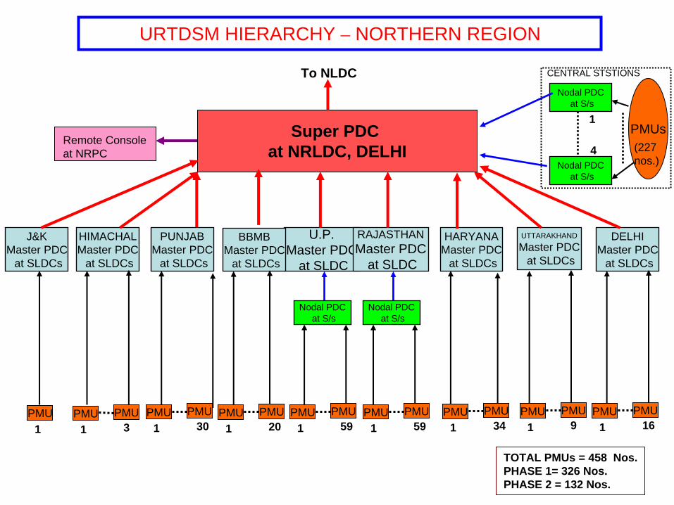
Super PDC at NRLDC, DELHI
URTDSM HIERARCHY – NORTHERN REGION
Nodal PDCat S/s
Nodal PDCat S/s
PMUs(227nos.)
1
4
To NLDC
Remote Console at NRPC
TOTAL PMUs = 458 Nos.PHASE 1= 326 Nos.PHASE 2 = 132 Nos.
U.P.Master PDC
at SLDC
Nodal PDCat S/s
J&KMaster PDC
at SLDCs
RAJASTHANMaster PDC
at SLDC
Nodal PDCat S/s
HIMACHALMaster PDC
at SLDCs
PUNJABMaster PDC
at SLDCs
HARYANAMaster PDC
at SLDCs
UTTARAKHAND
Master PDCat SLDCs
DELHIMaster PDC
at SLDCs
1PMU
1PMU PMU
3 1PMU PMU
30 1PMU PMU
59 1PMU PMU
59 1PMU PMU
34 1PMU PMU
9 1PMU PMU
16
CENTRAL STSTIONS
BBMBMaster PDC
at SLDCs
1PMU PMU
20

APPENDIX Southern Region

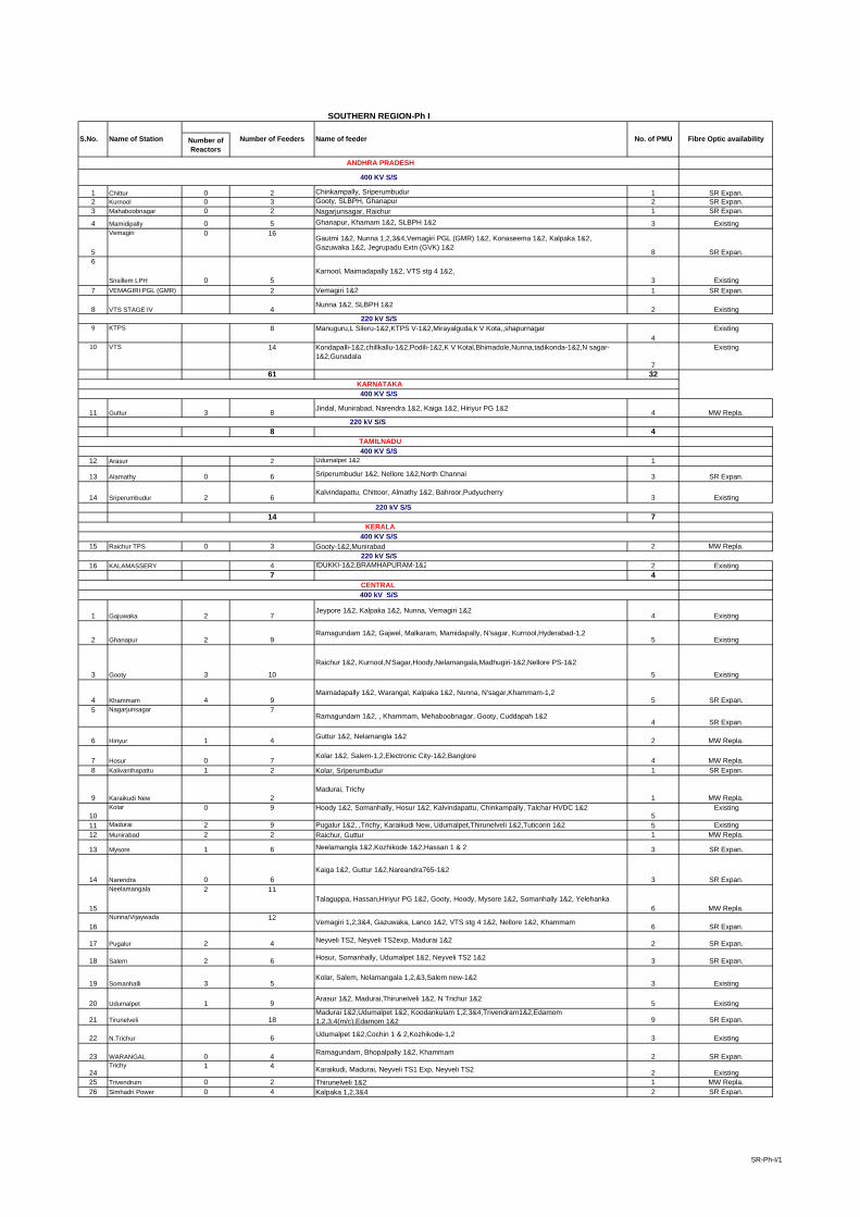
Number of Reactors
1 0 2 Chinkampally, Sriperumbudur 1 SR Expan.2 Kurnool 0 3 Gooty, SLBPH, Ghanapur 2 SR Expan.3 Mahaboobnagar 0 2 Nagarjunsagar, Raichur 1 SR Expan.
4 Mamidipally 0 5 Ghanapur, Khamam 1&2, SLBPH 1&2 3 Existing
5
Vemagiri 0 16Gautmi 1&2, Nunna 1,2,3&4,Vemagiri PGL (GMR) 1&2, Konaseema 1&2, Kalpaka 1&2, Gazuwaka 1&2, Jegrupadu Extn (GVK) 1&2
8 SR Expan.6
Srisillem LPH 0 5Karnool, Maimadapally 1&2, VTS stg 4 1&2,
3 Existing7 VEMAGIRI PGL (GMR) 2 Vemagiri 1&2 1 SR Expan.
8 VTS STAGE IV 4Nunna 1&2, SLBPH 1&2
2 Existing
9 KTPS 8 Manuguru,L Sileru-1&2,KTPS V-1&2,Mirayalguda,k V Kota,,shapurnagar4
Existing
10 VTS 14 Kondapalli-1&2,chillkallu-1&2,Podili-1&2,K V Kotal,Bhimadole,Nunna,tadikonda-1&2,N sagar-1&2,Gunadala
7
Existing
61 32
11 Guttur 3 8 Jindal, Munirabad, Narendra 1&2, Kaiga 1&2, Hiriyur PG 1&2 4 MW Repla.
8 4
12 Arasur 2 Udumalpet 1&2 1
13 Alamathy 0 6 Sriperumbudur 1&2, Nellore 1&2,North Channai 3 SR Expan.
14 Sriperumbudur 2 6Kalvindapattu, Chittoor, Almathy 1&2, Bahroor,Pudyucherry
3 Existing
14 7
15 Raichur TPS 0 3 Gooty-1&2,Munirabad 2 MW Repla.
16 KALAMASSERY 4 IDUKKI-1&2,BRAMHAPURAM-1&2 2 Existing7 4
1 Gajuwaka 2 7Jeypore 1&2, Kalpaka 1&2, Nunna, Vemagiri 1&2
4 Existing
2 Ghanapur 2 9Ramagundam 1&2, Gajwel, Malkaram, Mamidapally, N'sagar, Kurnool,Hyderabad-1,2
5 Existing
3 Gooty 3 10
Raichur 1&2, Kurnool,N'Sagar,Hoody,Nelamangala,Madhugiri-1&2,Nellore PS-1&2
5 Existing
4 Khammam 4 9Maimadapally 1&2, Warangal, Kalpaka 1&2, Nunna, N'sagar,Khammam-1,2
5 SR Expan.5 Nagarjunsagar 7
Ramagundam 1&2, , Khammam, Mehaboobnagar, Gooty, Cuddapah 1&24 SR Expan.
6 Hiriyur 1 4 Guttur 1&2, Nelamangla 1&2 2 MW Repla.
7 Hosur 0 7Kolar 1&2, Salem-1,2,Electronic City-1&2,Banglore
4 MW Repla.8 Kalivanthapattu 1 2 Kolar, Sriperumbudur 1 SR Expan.
9 Karaikudi New 2Madurai, Trichy
1 MW Repla.
10Kolar 0 9 Hoody 1&2, Somanhally, Hosur 1&2, Kalvindapattu, Chinkampally, Talchar HVDC 1&2
5Existing
11 Madurai 2 9 Pugalur 1&2, ,Trichy, Karaikudi New, Udumalpet,Thirunelveli 1&2,Tuticorin 1&2 5 Existing12 Munirabad 2 2 Raichur, Guttur 1 MW Repla.
13 Mysore 1 6 Neelamangla 1&2,Kozhikode 1&2,Hassan 1 & 2 3 SR Expan.
14 Narendra 0 6Kaiga 1&2, Guttur 1&2,Nareandra765-1&2
3 SR Expan.
15
Neelamangala 2 11Talaguppa, Hassan,Hiriyur PG 1&2, Gooty, Hoody, Mysore 1&2, Somanhally 1&2, Yelehanka
6 MW Repla.
16Nunna/Vijaywada 12 Vemagiri 1,2,3&4, Gazuwaka, Lanco 1&2, VTS stg 4 1&2, Nellore 1&2, Khammam 6 SR Expan.
17 Pugalur 2 4 Neyveli TS2, Neyveli TS2exp, Madurai 1&2 2 SR Expan.
18 Salem 2 6 Hosur, Somanhally, Udumalpet 1&2, Neyveli TS2 1&2 3 SR Expan.
19 Somanhalli 3 5Kolar, Salem, Nelamangala 1,2,&3,Salem new-1&2
3 Existing
20 Udumalpet 1 9Arasur 1&2, Madurai,Thirunelveli 1&2, N Trichur 1&2
5 Existing
21 Tirunelveli 18Madurai 1&2,Udumalpet 1&2, Koodankulam 1,2,3&4,Trivendram1&2,Edamom 1,2,3,4(m/c),Edamom 1&2 9 SR Expan.
22 N.Trichur 6 Udumalpet 1&2,Cochin 1 & 2,Kozhikode-1,2 3 Existing
23 WARANGAL 0 4 Ramagundam, Bhopalpally 1&2, Khammam 2 SR Expan.
24Trichy 1 4 Karaikudi, Madurai, Neyveli TS1 Exp, Neyveli TS2 2 Existing
25 Trivendrum 0 2 Thirunelveli 1&2 1 MW Repla.26 Simhadri Power 0 4 Kalpaka 1,2,3&4 2 SR Expan.
CENTRAL 400 kV S/S
KERALA400 KV S/S
220 kV S/S
SOUTHERN REGION-Ph I
Number of FeedersName of Station No. of PMUName of feeder
TAMILNADU400 KV S/S
220 kV S/S
220 kV S/S
KARNATAKA 400 KV S/S
220 kV S/S
Fibre Optic availability
ANDHRA PRADESH
400 KV S/S
Chittur
S.No.
SR-Ph-I/1

27 Nellore 3 8 Sriperumubudur 1 & 2,Krishnapatnam UMPP-1&2 ,Vijayawada-1,2,Thiruvalem-1,2 4 Sr Expan.28 Kaiga Atomic Power Stn 0 6 Narendra 1&2, Guttur 1&2,Sirsi-2 3 SR Expan.
29 Neyveli TS1 Ext. 0 2 Neyveli TS 2, Trichy 1 SR Expan.
30Neyveli TS2 0 7 Salem 1&2, Trichy, Neyveli TS1 Exp,Neyveli TS2, Bahror,Puducherry 4 SR Expan.
31 Neyveli TS2 Exp 2 Pugalur, Neyveli TS1 1 SR Expan.
32
guttur+A61 5Mehaboobnagar, Gooty 1&2, BTPS,Munirabad
3 MW Repla.
33Ramagundam STPS 3 10 Chandrapur 1&2, Warangal, Nagarjuna Sagar 1&2,Ghanapur 1&2, Gajwel, Malkaram, Dichipally 5 SR Expan.
34
Kurnool765 9Nellore-1&2,Raichur-1,N,sagar-1,Gooty-1,Kurnool(AP)-1&2,Thiruvalem-1,2
5 SR Expan.
35
Raichur765 7Kurnool-1&2,Raichur-1&2,Gooty-1&2,Sholapur-1
4 SR Expan.
36 Narendra 765 6 Kolhapur-1&2,Narendra-1&2,Madhugri-1,2 3 SR Expan.
37Madhugiri765 7
Gooty-1&2,Yelahanka 1 &2,New Salem-1,Narendra-1,24 SR Expan.
38Yelahanka 6 Neelamangla-1 ,Hoody-1&2,Somanhally-1,Madhugiri-1&2 3 SR Expan.
39Hassan 3 Mysore 1&2,Neelmangalam 2 SR Expan.
40Bidadi 4 Neelamangla 1 & 2,Somnahalli 1 & 2 2 SR Expan.
41Cuddappah PG 3 Nagarjunsagar-1,2,Chitoor 2 SR Expan.
42Nagapattanam PS 4 Neyveli -1, Trichy-1,Salem new-1,2 2 SR Expan.
43Neyveli TS 6 Neyveli TS2, Neyveli TS2exp, Madurai 1&2
3 SR Expan.
44Thiruvanthapuram 6
3 SR Expan.
45Salem PS 5 Somanahalli-1&2,Nagapattanam PS-1,2,Madugiri-1 3 SR Expan.
46Cochin 4 Edamom 1,2(D/C),North Trichur 1,2 (D/C) 2 SR Expan.
47Puducherry 2 Neyveli TS2,Sriparembadur
1 SR Expan.
48Kundakulam 4 Tiruneveli 1,2,3,4 2 SR Expan.
49Kozhikode 2 Mysore 1&2 1 SR Expan.
50 Kayamkulam PG 6 3 SR Expan.
51
Edamom 8Tirunelveli 1,2,3,4(M/C),Tirunelveli 6 &7(D/C),Muvattupuzha 1,2(D/C)
4 MW Repla.52 PFBR Kalpakkam 6 Kanchepuram 1 &2,Arni 1&2,Sirucheri 1&2 3 SR Expan.53 Tiruvalam 10 Chitoor-1,2,Nellore 1,2,Sholinganallur-1,2,Kurnool-1,2,Kolar-1,Sriperumbudur-1 5 SR Expan.54 765 kV Nellore 8 Simhapuri – 1&2,Nellore-1&2,Kurnool-1&2,Gooty 1&2 4 SR Expan.55 Hyderabad 4 Wardha-1,2,Ghanapur-1,2 2 SR Expan.56 Vemagiri(765)-PS 2 Gazuwaka ,Vijayawada 1 SR Expan.57 Khammam-765 2 Khammam 1&2, 1 SR Expan.
338 178
SR-Ph-I/2

1 Upper Sileru 5 Kolar, Chittoor, N'Sagar 1&2,Balimela 3 No
2 Dichpally 1 Ramagundam 1 No
3 Gajwal 2Ramagundam
1 No4
Gautami Power Stn 2 Vemagiri 1&2 1 No5 Kalpaka 10 Khammam 1&2, Vemagiri 1&2, Simadri 1,2,3&4, Gazuwaka 1&2 5 No6 MALKARAM 2 Ghanapur, Ramagundam 1 No7 BHOOPALAPPALLY 2 Warangal 1&2 1 No
8 KONASEEMA 2Vemagiri 1&2
1 No
9 JEGRUPADU EXTN (GVK) 2 Vemagiri 1&2 1 No10 LANCO 2 Nunna 1&2 1 No
11 Upper Sileru 3 Pendurthi,Donikarayi,Balimela 2 No12 Lower Sileru 6 Barasur-1&2,KTPS-1&2,Bommur, Donkarai 3 No13 Vijjeswaram-I 2 Bommur,Bhimadole 1 No14 Vijjeswaram-II 5 Bommur-1&2,Nidadavolu-1&2,K.V.Kota 3 No15 Jegurupadu 2 Bommur,Nidadavolu 1 No16 Spectrum 2 Kakinada-1&2 1 No
17 Jurala 2 Mehaboobnagar-1&2 1 No18 Muddanur 8 Anantpur-1&2,Yerraguntla-1&2,Pulvendula-1&2,chinakampally-1&2 4 No
60 32
19 BTPS 2 Raichur, Jindal 1 No20 Hoody 4 Kolar 1&2, Gooty,Nelamangala 2 No21 KUDITINI 2 Alipur, Lingapur 1 No22 JINDAL 2 Guttur, BTPS 1 No
23 Almatty 2 Bagalkot,b Bagewadi 1 No24 Belgaum 4 Narendra, chikkodi 2 No25 Lingapur 10 Kushtagi,Sindhanur,Kuditini,Ittagi,Gaitag,Enercon,Munirabad-1&2,JSW-1&2 5 No26 JSW 2 Lingapur-1&2 1 No27 Supa 2 Ambewadi,ponda 1 No28 Nagjheri 8 Ambewadi-1&2,Hubli-1,2,3&4,Kodasalli-1&2 4 No29 Kadra 4 Ambewadi,Kaliga,Karwar-1&2 2 No30 Jog 2 Sharawat.shimoga 1 No31 Sharawti 9 Shimoga-1,2,3&4,Talaguppa-1&2,Hubli-1&2,Jog 5 No32 S.Tail Race 2 Talaguppa-1&2 1 No33 Varahi 2 Shimoga,kemar 1 No34 Kodasalli 4 Nagjahri-1&2,Kaiga, kadra 2 No35 Chikodi 2 Kholapur-1,2 1 No36 Ambewadi 2 Ponda-1,2 1 No
65 33
37 Sholinganallur 2 Tiruvalam -1,2 1 No
38 NORTH CHENNAI 8HI-TECH,ENNORE,TONDIARPET-1&2,KILPURK,S P BUDUR,MOSUR,ALMATHY 4 No
39 HI-TECH 2 NORTH CHENNAI,GUMMDIPOONDI 1 No40 ENNORE 3 NORTH CHENNAI,MANALI,TONDIARPET 2 No41 METTUR TPS 8 SALEM-1,2&3,SINGARAPETTAI,METTUR,METTUR TUNNEL,GOBI,INGUR 4 No42 METTUR TUNNEL 2 METTUR TPS,METTUR 1 No43 PYKARA ULTIMATE 2 ARASUR,KUNDAH 3 1 No
44 KUNDAH 3 3 KUNDAH 1,KUNDAH 2,PYKARA ULTIMATE 2 No45 KUNDAH 1 2 KUNDAH 3,THUDIYALUR 1 No
46 KUNDAH 2 2 KUNDAH 3,ARASUR 1 No47 KADAMPARAI 3 UDULMALPET,UDULMALPET(MYVADI)-1&2 2 No48 P P NALLUR 3 THIRUVARUR,KADALANGUDI-1&2 2 No49 TUTICORIN 9 1&2,AUTO-1&2,PARAMAKUDI 5 No
49 27
50 Talaguppa 3Hassan-1,Neelmangala-1,2
2 No
51 Kasarkode 2 Vadakkara,kanjirode 1 No52 BRAMHAPURAM 4 LOWER PERIYAR-1&2,KALAMASSERY-1&2 2 No53 LOWER PERIYAR 6 IDUKKI-1&2,BRAMHAPURAM-1&2,Trichur-1&2 3 No54 SABRIGIRI 6 PALLOM-1&2,EDAMON-1,2&3,THENI 3 No55 KAYAMKULAM 4 NEW PALOM-1&2,KUNDARA,EDAPPON 2 No
Number of Feeders
SOUTHERN REGION - Ph II
KERALA400 KV S/S
No. of PMU
KARNATAKA 400 KV S/S
Name of feeder
220 kV S/S
220 kV S/S
220 kV S/S
TAMILNADU400 KV S/S
Fibre Optic availability
ANDHRA PRADESH
400 KV S/S
S.No. Name of Station
SR-Ph-II/1

25 13
56 North Chennai 4 Sriperumbudur 1& 2 , Alamathy 1 & 2 2 No57 Tuticorin 2 Madurai 1&2 1 No
58Chulliar /Erlapalli 4 Udumalpet 1 & 2, Madakathara (North Trichur) 1 & 2 2 No
10 5
CENTRAL 400 kV S/S
SR-Ph-II/2

Udumalpet
TrichurNorth
Kalamassery SLDC
Chalakudy
Pallom Edappon Kundra Trivendrum(North)
HYDERABADSLDC
Ghanapur
Shapur Nagar
WARRANGAL
Ramagundam/ Mamidipally
DURSHED
Cochin
Hyderabad Pooling Station
Palakad
KO
ZHIK
OD
E B
SRISAILAM LBPH
RamagundamNTPC
Warangal PG
Vijayawada VTPS
Khammam PG
VeemagiriPooling Station
KarnoolAPTRANSCO
Somayajulapally
Gooty
Somanhally
Bidadi
Neelmangala
Mysore
Kozhikode
Hassan
HiriyurDavangere/Gutur
Munirabad
Raichur400kV
Raichur 765kV
Yelahanka
Madhugiri765kV
Narendra765kV
Kaiga
Bhimadole
Bommur
Kakinada
Veemagiri
GazuwakaVishkahapatnamSRISAILAM PH
Tallapally
N’Sagar PH
Ananthpur
Muddanur
Ch’Pally Sub-LDC Cuddappah PG ChittorAPTRANSCO
Kolar
Nellore
SriperambudurAlamathy
Chennai SLDC
HosurMPTS (TNEB)Arasur
Salem 400kV
Edamon
Nagapattanam PS
Salem 230kV
Madurai 400kV
Erode
Trichy 230 kV
Thiruvarur 230kV
Tanjore 230kV
Trichy 400kV TNEB
Trichy 400kV PGKaraikudi
Karaikudi400kV
S.P. Koil
Neyveli TS-I
PugalurNeyvelliTS2 Exp.
NeyvelliTS2
NeyvelliTS1 Exp.
Pon
dy
Madurai Sub-LDC
Villianur
Pondicherry SCC
Tiru
nelv
eli
Thiruvananthapuram
Kundakulam
Kalivanthapattu
Kayakulam PG
Narendra400kV
Salem Pooling Stn.
Mehboob Nagar
Simhadri -II
220kV KhammamAPTRANSCO
Kurnool 765kV
220kV KTPS APTRANSCO
NAGARJUN SAGAR
104
189
FIBRE OPTIC COMMUNICATION NETWORK WITH PMU LOCATION IN SOUTHERN REGION –Phase-I
SLDC/ PROP. MPDC LOCATION
SUBSTATION
EXIST. FO CABLE
FO CABLE UNDER EXPANSION PROJ.
Legends:
Proposed Location of PMU
FO CABLE UNDER MW REPLAC. PROJ.
SRLDC
RLDC/ PROP. SPDC LOCATION

Super PDC at SRLDC, BANGLORE
URTDSM HIERARCHY – SOUTHERN REGION
Nodal PDCat S/s
Nodal PDCat S/s
PMUs(183 nos.)
1
3
To NLDC
Remote Console at SRPC
Remote Console at PONDY
KERALAMaster PDC
at SLDCs
PMU PMU1 17
TOTAL PMUs = 335 Nos.PHASE 1= 225 Nos.PHASE 2 = 110 Nos.
KARNATAKAMaster PDC
at SLDCs
PMU PMU1 37
TAMILNADUMaster PDC
at SLDCs
PMU PMU1 34
A.P.Master PDC
at SLDC
Nodal PDCat S/s
Nodal PDCat S/s
PMUs(64nos.)
CENTRAL STATIONS

APPENDIX Western Region

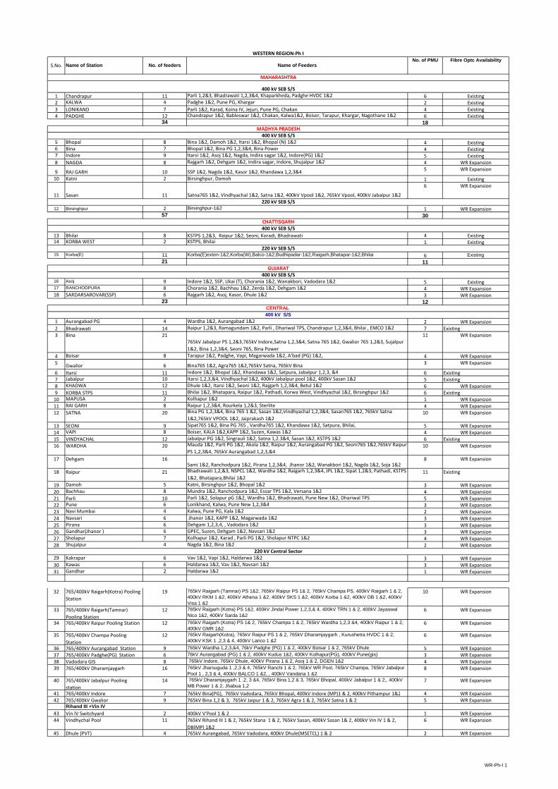
1 Chandrapur 11 Parli 1,2&3, Bhadrawati 1,2,3&4, Khaparkheda, Padghe HVDC 1&2 6 Existing2 KALWA 4 Padghe 1&2, Pune PG, Khargar 2 Existing3 LONIKAND 7 Parli 1&2, Karad, Koina IV, Jejuri, Pune PG, Chakan 4 Existing4 PADGHE 12 Chandrapur 1&2, Bableswar 1&2, Chakan, Kalwa1&2, Boiser, Tarapur, Khargar, Nagothane 1&2 6 Existing
34 18
5 Bhopal 8 Bina 1&2, Damoh 1&2, Itarsi 1&2, Bhopal (N) 1&2 4 Existing6 Bina 7 Bhopal 1&2, Bina PG 1,2,3&4, Bina Power 4 Existing7 Indore 9 Itarsi 1&2, Asoj 1&2, Nagda, Indira sagar 1&2, Indore(PG) 1&2 5 Existing8 NAGDA 8 Rajgarh 1&2, Dehgam 1&2, Indira sagar, Indore, Shujalpur 1&2 4 WR Expansion
9 RAJ GARH 10 SSP 1&2, Nagda 1&2, Kasor 1&2, Khandawa 1,2,3&4 5 WR Expansion
10 Katni 2 Birsinghpur, Damoh 1 Existing
11 Sasan 11 Satna765 1&2, Vindhyachal 1&2, Satna 1&2, 400kV Vpool 1&2, 765kV Vpool, 400kV Jabalpur 1&2
6 WR Expansion
12 Birsinghpur 2 Birsinghpur-1&2 1 WR Expansion57 30
13 Bhilai 8 KSTPS 1,2&3, Raipur 1&2, Seoni, Koradi, Bhadrawati 4 Existing14 KORBA WEST 2 KSTPS, Bhilai 1 Existing
15 Korba(E) 11 Korba(E)exten-1&2,Korba(W),Balco-1&2,Budhipadar-1&2,Raigarh,Bhatapar-1&2,Bhilai 6 Existing21 11
16 Asoj 9 Indore 1&2, SSP, Ukai (T), Chorania 1&2, Wanakbori, Vadodara 1&2 5 Existing17 RANCHODPURA 8 Chorania 1&2, Bachhau 1&2, Zerda 1&2, Dehgam 1&2 4 WR Expansion18 SARDARSAROVAR(SSP) 6 Rajgarh 1&2, Asoj, Kasor, Dhule 1&2 3 WR Expansion
23 12
1 Aurangabad PG 4 Wardha 1&2, Aurangabad 1&2 2 WR Expansion2 Bhadrawati 14 Raipur 1,2&3, Ramagundam 1&2, Parli , Dhariwal TPS, Chandrapur 1,2,3&4, Bhilai , EMCO 1&2 7 Existing3 Bina 21
765kV Jabalpur PS 1,2&3,765kV Indore,Satna 1,2,3&4, Satna 765 1&2, Gwalior 765 1,2&3, Sujalpur 1&2, Bina 1,2,3&4, Seoni 765, Bina Power
11 WR Expansion
4 Boisar 8 Tarapur 1&2, Padghe, Vapi, Magarwada 1&2, A'bad (PG) 1&2, 4 WR Expansion5 Gwalior 6 Bina765 1&2, Agra765 1&2,765kV Satna, 765kV Bina 3 WR Expansion
6 Itarsi 11 Indore 1&2, Bhopal 1&2, Khandawa 1&2, Satpura, Jabalpur 1,2,3, &4 6 Existing7 Jabalpur 10 Itarsi 1,2,3,&4, Vindhyachal 1&2, 400kV Jabalpur pool 1&2, 400kV Sasan 1&2 5 Existing8 KHADWA 12 Dhule 1&2, Itarsi 1&2, Seoni 1&2, Rajgarh 1,2,3&4, Betul 1&2 6 WR Expansion9 KORBA STPS 11 Bhilai 1&2, Bhatapara, Raipur 1&2, Pathadi, Korwa West, Vindhyachal 1&2, Birsinghpur 1&2 6 Existing10 MAPUSA 2 Kolhapur 1&2 1 WR Expansion11 RAI GARH 8 Raipur 1,2,3&4, Rourkela 1,2&3, Sterlite 4 WR Expansion12 SATNA 20 Bina PG 1,2,3&4, Bina 765 1 &2, Sasan 1&2,Vindhyachal 1,2,3&4, Sasan765 1&2, 765kV Satna
1&2,765kV VPOOL 1&2, Jaiprakash 1&210 WR Expansion
13 SEONI 9 Sipat765 1&2, Bina PG 765 , Vardha765 1&2, Khandawa 1&2, Satpura, Bhilai, 5 WR Expansion14 VAPI 8 Boiser, KALA 1&2,KAPP 1&2, Suzen, Kawas 1&2 4 WR Expansion15 VINDYACHAL 12 Jabalpur PG 1&2, Singrauli 1&2, Satna 1,2.3&4, Sasan 1&2, KSTPS 1&2 6 Existing16 WARDHA 20 Mauda 1&2, Parli PG 1&2, Akola 1&2, Raipur 1&2, Aurangabad PG 1&2, Seoni765 1&2,765kV Raipur
PS 1,2,3&4, 765kV Aurangabad 1,2,3,&410 WR Expansion
17 Dehgam 16Sami 1&2, Ranchodpura 1&2, Pirana 1,2,3&4, Jhanor 1&2, Wanakbori 1&2, Nagda 1&2, Soja 1&2
8 WR Expansion
18 Raipur 21 Bhadrawati 1,2,&3, NSPCL 1&2, Wardha 1&2, Raigarh 1,2,3&4, JPL 1&2, Sipat 1,2&3, Pathadi, KSTPS 1&2, Bhatapara,Bhilai 1&2
11 Existing
19 Damoh 5 Katni, Birsinghpur 1&2, Bhopal 1&2 3 WR Expansion20 Bachhau 8 Mundra 1&2, Ranchodpura 1&2, Essar TPS 1&2, Versana 1&2 4 WR Expansion21 Parli 10 Parli 1&2, Solapur pG 1&2, Wardha 1&2, Bhadrawati, Pune New 1&2, Dhariwal TPS 5 WR Expansion22 Pune 6 Lonikhand, Kalwa, Pune New 1,2,3&4 3 WR Expansion23 Navi Mumbai 4 Kalwa, Pune PG, Kala 1&2 2 WR Expansion24 Navsari 6 Jhanor 1&2, KAPP 1&2, Magarwada 1&2 3 WR Expansion25 Pirana 6 Dehgam 1,2,3,4, , Vadodara 1&2 3 WR Expansion26 Gandhar(Jhanor ) 6 GPEC, Suzen, Dehgam 1&2, Navsari 1&2 3 WR Expansion27 Sholapur 7 Kolhapur 1&2, Karad , Parli PG 1&2, Sholapur NTPC 1&2 4 WR Expansion28 Shujalpur 4 Nagda 1&2, Bina 1&2 2 WR Expansion
29 Kakrapar 6 Vav 1&2, Vapi 1&2, Haldarwa 1&2 3 WR Expansion30 Kawas 6 Haldarwa 1&2, Vav 1&2, Navsari 1&2 3 WR Expansion31 Gandhar 2 Haldarwa 1&2 1 WR Expansion
32 765/400kV Raigarh(Kotra) Pooling Station
19 765kV Raigarh (Tamnar) PS 1&2, 765kV Raipur PS 1& 2, 765kV Champa PS, 400kV Raigarh 1 & 2, 400kV RKM 1 &2, 400kV Athena 1 &2, 400kV SKS 1 &2, 400kV Korba 1 &2, 400kV DB 1 &2, 400kV Visa 1 &2
10 WR Expansion
33 765/400kV Raigarh(Tamnar) Pooling Station
12 765kV Raigarh (Kotra) PS 1&2, 400kV Jindal Power 1,2,3,& 4, 400kV TRN 1 & 2, 400kV Jayaswal Nico 1&2, 400kV Sarda 1&2
6 WR Expansion
34 765/400kV Raipur Pooling Station 12 765kV Raigarh (Kotra) PS 1& 2, 765kV Champa 1 & 2, 765kV Wardha 1,2,3 &4, 400kV Raipur 1 & 2, 400kV GMR 1&2
6 WR Expansion
35 765/400kV Champa Pooling Station
12 765kV Raigarh(Kotra), 765kV Raipur PS 1 & 2, 765kV Dharamjaygarh , Kurushetra HVDC 1 & 2, 400kV KSK 1 ,2,3 & 4, 400kV Lanco 1 &2
6 WR Expansion
36 765/400kV Aurangabad Station 9 765kV Wardha 1,2,3,&4, 76kV Padghe (PG) 1 & 2, 400kV Boisar 1 & 2, 765kV Dhule 5 WR Expansion37 765/400kV Padghe(PG) Station 6 76kV Aurangabad (PG) 1 & 2, 400kV Kudus 1&2, 400kV Kolhapur(PG), 400kV Pune(gis) 3 WR Expansion38 Vadodara GIS 8 765kV Indore, 765kV Dhule, 400kV Pirana 1 & 2, Asoj 1 & 2, DGEN 1&2 4 WR Expansion39 765/400kV Dharamjaygarh 16 765kV Jharsuguda 1 ,2,3 & 4, 765kV Ranchi 1 & 2, 765kV WR Pool, 765kV Champa, 765kV Jabalpur
Pool 1 , 2,3 & 4, 400kV BALCO 1 &2, , 400kV Vandana 1 &28 WR Expansion
40 765/400kV Jabalpur Pooling station
14 765kV Dharamjaygarh 1 ,2, 3 &4, 765kV Bina 1,2 & 3, 765kV Bhopal, 400kV Jabalpur 1 & 2,, 400kV MB Power 1 & 2, Jhabua 1,2
7 WR Expansion
41 765/400kV Indore 7 765kV Bina(PG), 765kV Vadodara, 765kV Bhopal, 400kV Indore (MP)1 & 2, 400kV Pithampur 1&2 4 WR Expansion42 765/400kV Gwalior 9 765kV Bina 1,2 & 3, 765kV Jaipur 1 & 2, 765kV Agra 1 & 2, 765kV Satna 1 & 2 5 WR Expansion
Rihand III +Vin IV43 Vin IV Switchyard 2 400kV V'Pool 1 & 2 1 WR Expansion44 Vindhychal Pool 11 765kV Rihand III 1 & 2, 765kV Stana 1 & 2, 765kV Sasan, 400kV Sasan 1& 2, 400kV Vin IV 1 & 2,
DB(MP) 1&26 WR Expansion
45 Dhule (PVT) 4 765kV Aurangabad, 765kV Vadodara, 400kV Dhule(MSETCL) 1 & 2 2 WR Expansion
220 kV Central Sector
CHATTISGARH
400 kV S/S
220 kV SEB S/S
GUJARAT400 kV SEB S/S
CENTRAL
400 kV SEB S/S
220 kV SEB S/S
No. of feedersFibre Optc Availability
MAHARASHTRA
400 kV SEB S/S
WESTERN REGION‐Ph I
MADHYA PRADESH400 kV SEB S/S
Name of StationS.No.No. of PMU
Name of Feeders
WR-Ph-I 1

46 400kV Kolapur (PG) 6 765kV Narendra 1 & 2, 400kV Kolahpur 1 & 2, 400kV Mapusa 1 & 2 3 WR Expansion47 765/400kV Pune GIS 12 765kV Solapur 1&2, 400kV Solapur STPP 1&2, 400kV Kolhapur, 400kV Aurbd(existing) 1&2, 400kV
Parli(exs) 1&2, 400kV Padghe(GIS), 400kV HEGL 1,26 WR Expansion
48 Magarwada GIS 4 400kV Navsari 1 & 2, 400kV Boisar 1&2 2 WR ExpansionUT DNH
49 Kala GIS 4 400kV Vapi 1 & 2, 400kV Navi Mumbai 1&2 2 WR Expansion456 234
WR-Ph-I 2

1 Akola 6 Aurangabad 1&2,Wardha 1&2, Bhusawal, Koradi 3 No2 Aurangabad 10 Akola1&2, Aurangabad PG 1&2, Bhusawal , Bableswar, Bhusawal II 1&2, Pune (N) 1&2 5 No3 Bableshwar 6 Padghe 1&2, Dhule 1&2, Aurangabad, Bhusawal 3 No4 Bhusawal 6 Babhaleshwar, Aurangabad, Koradi, Bhusawal II 1&2, Akola 3 No5 Bhusawal II 4 Aurangabad 1&2, Bhusawal 1&2 2 No6 Dabhol 4 New Koina 1&2, Nagothane 1&2 2 No7 Dhule 6 Bableswar 1&2, Khandawa 1&2, SSP 1&2 3 No8 Jejuri 2 Koina IV, Lonikhand 1 No9 Jaigad 4 Karad 1&2, New Koina 1&2 2 No10 Karad 8 Sholapur PG, Kolhapur 1&2, Jaigad 1&2, New Koina 1&2, Lonikhand 4 No11 Khargar 2 Pdghe, Kalwa 1 No12 KOLHAPUR 4 Sholapur PG 1&2, Karad 1&2 2 No13 KORADI 5 Khaparkheda, Akola, Bhusawal, Satpura, Bhilai 3 No14 KOYNA IV 4 New Koina 1&2, Jejuri, Lonikhand 2 No15 NAGOTHANE 4 Dabhol 1&2, Padghe 1&2 2 No16 PARLI 8 Parli PG 1&2, Chandrapur 1,2&3, Solapur, Lonikhand 1&2 4 No17 SOLAPUR 2 Sholapur PG, Parli 1 No18 NEW KOYNA 10 Dabhol 1&2, Jaigad 1&2, Karad 1&2, Koina IV 1&2, JSW 1&2 5 No19 Khaperkheda 2 Chandrapur, Koradi 1 No
20 Nasik 8 Babhaleshwar-1&2,Navsari-1&2,Padghe-1&2,kalwa,R.steel 4 No21 Bhira 1 Kindalgaon 1 No22 Tillari 2 Gadhinglaj,TD Ponda Goa 1 No23 Paras 6 chikhali-1&2,Balapur MIDC-1&2,Apatapa-A1-1&2 3 No24 Uran 4 Apta-1,2,3&4,Kharghar 2 No25 Khaperkheda 6 Bhugaon, Wardha, Kalmeswar, Koradi, Ambazari 1&2 3 No26 Trombay 4 Kalwa-1,2&3,Kandalgaon 2 No
128 65
27 Indira sagar 4 Satpura, Indore 1&2, Nagda 2 No28 SATPURA 4 Koradi, Seoni, Itarsi, Indira Sagar 2 No29 Brisingpur 5 KSTPS 1&2, Damoh 1&2, Katni 3 No
30 Omkareswar 5 Kandwa,Nimrani,Julwania,Barwa-1&2 3 No31 Amarkantak 8 Birsinghpur‐1,2&3,Sidhi,jabalpur‐1&2,korba west‐1&2 4 No32 Bansgar sagar-I 4 Rewa-1&2,Santa-1&2 2 No
30 16
33 Korba(E)exten 4 Korba(E)-1&2,Korba(W)-1&2 2 No4 2
33 Chorania 9 Rachodpura 1&2, Kasor, Asoj 1&2, Amreli, Hadala, CGPL 1&2 5 No34 CGPL 6 Bachhau 1&2, Chorania 1&2, Jetpur 1&2 3 No35 GPEC 2 Jhanor, Kasor 1 No36 Hadala 6 Jetpur, Vadinar 1&2, APL, Varsana, Chorania 3 No37 Jetpur 4 Amreli, Hadala, CGPL 1&2 2 No38 KASOR 5 Rajgarh 1&2, Chorania, GPEC, SSP 3 No39 SOJA(nardipur) 4 Zerda ,Dehgam,Wanakbori 1&2 2 No40 UKAI(T) 2 Asoj 1&2 1 No41 WANAKBORI 3 Asoj, Dehgam 1&2 2 No42 Amreli 6 Chorania, Jetpur, Vadinar 1&2, Shahpoorji 1&2 3 No43 Zerda 11 Bhinmal, Kankroli, , APL 1,2,3 &4, Ranchodpur 1&2, Nardipur 1,2 &3 6 No44 Varsana 9 Mundra , Hadala , OPGG 1&2, Halvad 1,2&3, Bachau 1&2 5 No45 Halvad 8 Salaya 1&2, Varsana 1&2, Vadavi 1&2,Varsana, Hadala 4 No46 Sami 4 APL 1&2, Dehgam 1&2 2 No
47 Gandhi Nagar 8 Mehsana‐1&2,Asoja‐1&2,Chhatral‐1&2,Ranasan‐1&2 4 No48 Khadana 4 Dhansura-1&2,Godhra-1&2 2 No49 Ukai(H) 4 Achhalim-1,&2,Ukai(TH)-1&2 2 No50 Utran 1 Ichhapur 1 No51 Essar 2 Jamnagar-1&2 1 No52 GSEG 2 Kim-1&2 1 No53 Mangrol(Surat LPP) 4 Zagadia-1&2,Bharuch-1&2 2 No54 Sikka 2 Jamnagar-1&2 1 No55 Akrimota 4 Panendro-1&2,Nakhatrana-1&2 2 No56 Panendro 6 Anjar-1&2,Nakhatrana-1&2,Akrmota-1&2 3 No57 GPPL 2 Savarkundla,Kovaya 1 No
118 62
58 Bhatpara 2 Raipur, KSTPS 1 No59 Tarapur 4 Boiser 1&2, Padghe, Dahanu BSES 2 No60 SIPAT 8 Seoni765 1&2, Ranchi 1&2, Raipur 1,2&3, Pathad 4 No
14 761 NPCIL (Kakrapar) 4 400kV Navsari1&2, Vapi 1&2 2 No62 WR POOL 13 765kV Sipat 1 & 2, 765kV Seoni 1 ,2, & 3, 765kV Dharamjaygarh , 400kV Dheeru 1 &2,
400kV ACB(MCCPL) 1 &2, 400kV Mahan 400kV , 400kV Pathadi 1&2 7 No
63 Bhopal (PVT) 4 765kV Jabalpur Pool, 765kV Indore, 400kV Bhopal(MP) 1 & 2 2 No64 Solapur STPP 4 Solapur (PG) 1& 2, Pune PG 1 & 2 2 No
WESTERN REGION ‐ Ph II
MADHYA PRADESH400 kV SEB S/S
Name of StationS.No.No. of PMU
220 kV SEB S/S
Name of Feeders
220 kV SEB S/S
No. of feedersFibre Optc Availability
MAHARASHTRA400 kV SEB S/S
220 kV Central Sector
CHATTISGARH
400 kV S/S
220 kV SEB S/S
GUJARAT400 kV SEB S/S
220 kV SEB S/S
CENTRAL
400 kV SEB S/S
Wr-Ph-II 1

65 765kV Solapur 4 765kV Raichur 1&2, 765kV Pune 1&2 2 No66 Mauda 2 Wardha 1 & 2 167 Betul 3 400kV Khandwa 1 & 2 , Mauda II 268 Mauda II STPP 2 Betul 1 & 2 1
64 33
Wr-Ph-II 2
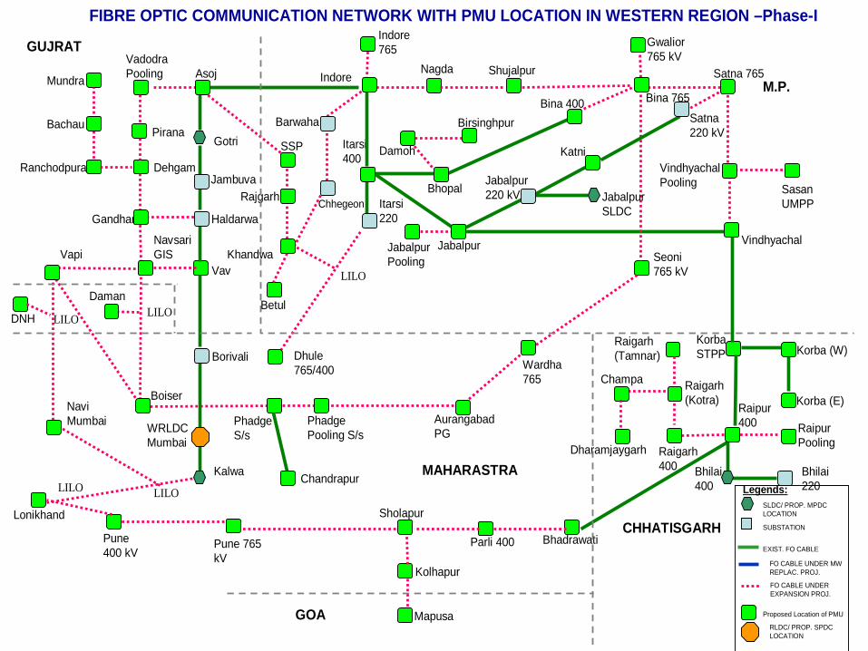
FIBRE OPTIC COMMUNICATION NETWORK WITH PMU LOCATION IN WESTERN REGION –Phase-I
Bachau
Ranchodpura
Mundra
Dehgam
Pirana
VadodraPooling
Gandhar Haldarwa
Asoj
Gotri
Jambuva
NavsariGIS
Vav
Borivali
Vapi
DNH
Indore
Itarsi400
SSP
Rajgarh
Khandwa
Itarsi220
Dhule765/400
Nagda Shujalpur
Bina 765
Indore 765 Gwalior
765 kV
Bhopal
Bina 400
Damoh
Birsinghpur
Satna 765
Jabalpur Vindhyachal
SasanUMPP
VindhyachalPooling
KorbaSTPP Korba (W)
Korba (E)Raipur 400
Bhilai400
Bhilai220
Raipur Pooling
Raigarh400
Raigarh(Kotra)
Raigarh(Tamnar)
Champa
Dharamjaygarh
Daman
NaviMumbai
Boiser
PhadgeS/s
Aurangabad PG
Wardha765
Seoni765 kV
BhadrawatiParli 400
Sholapur
Pune 765 kV
Pune400 kV
Mapusa
Kolhapur
Jabalpur SLDC
Jabalpur Pooling
Jabalpur 220 kV
Katni
Satna220 kV
Kalwa
WRLDC Mumbai
Lonikhand
LILOLILO
LILO
LILOLILO
PhadgePooling S/s
Barwaha
Chhegeon
GUJRAT
MAHARASTRA
M.P.
CHHATISGARH
GOA
Chandrapur
Betul
SLDC/ PROP. MPDC LOCATION
SUBSTATION
EXIST. FO CABLE
FO CABLE UNDER EXPANSION PROJ.
Legends:
Proposed Location of PMU
FO CABLE UNDER MW REPLAC. PROJ.
RLDC/ PROP. SPDC LOCATION

Super PDC at WRLDC, MUMBAI
URTDSM HIERARCHY – WESTERN REGION
M.P.Master PDC
at SLDC
CHATTISGARHMaster PDC
at SLDCs
MAHARASHTRAMaster PDC
at SLDC
GUJRATMaster PDC
at SLDC
Nodal PDCat S/s
PMU PMU1 46
PMU PMU1 13
Nodal PDCat S/s
Nodal PDCat S/s
PMUs(83nos.)
Nodal PDCat S/s
Nodal PDCat S/s
PMUs(74 nos.)
Nodal PDCat S/s
Nodal PDCat S/s
PMUs(267nos.)
1
6
To NLDC
Remote Console at WRPC
Remote Console at Goa, DD &DNH
TOTAL PMUs = 483 Nos.PHASE 1= 305 Nos.PHASE 2 = 178 Nos.
CENTRAL STATIONS

APPENDIX Eastern Region


Name of Station No. of feeders Name of Feeder No. of PMU FO Availability
1 Arambagh 5 PPSP 1&2, Baekeshwar, Kolaghat,Bidhinagar 3 MW Replac.2 Bakreshwar 2 Jeerat, Arambagh 1 MW Replac.3 Bidhannagar 7 PPSP 1&2, Arambag, Durgapur 1 & 2, DPL 1&2 4 MW Replac.4 Jeerat 4 Bahrampur, BKTPP, Kolaghat, Rajarhat 2 MW Replac.5 KOLAGHAT 3 Jeerat, Baripara, Arambag 2 MW Replac.6 Purulia PSP 4 Arambag 1&2, Bidhannagar 1&2 2 MW Replac.
7 Kasba 5 Jeerat-1&2, New Town, Budge-Budge 1&2 3 MW Replac.8 Kolaghat 4 Haldwara 1&2, Howrha 1&2 2 MW Replac.9 Bakreshwar 6 Bidhannagar 1&2, Gokarna 1&2, Santagachia 1&2 3 MW Replac.
40 22
10 DSTPS 2 Mejia,Maithon 1 MW Replac.11 Kodarma TPS 4 Biharshariff-1,2,Gaya 1,2 2 MW Replac.12 Mejia-b 4 Maithon 1,2 &3, Jamshedpur 2 MW Replac.13 Maithon RB TPS 4 Ranchi (PG) 1&2, Maithon 1&2 2 MW Replac.14 Bokaro TPS 2 Koderma 1,2 1 MW Replac.15 Durgapur TPS 4 Raghunathpur 1&2,Jamshedpur 1&2 2 MW Replac.16 Raghunathpur TPS 6 Maithon, Ranchi 1,2&3, Durgapur TPS 1&2 3 MW Replac.17 Mejia 6 Waria-1&2,Chandrapur-1&2,Kalswari-1&2 3 MW Replac.18 Waria(DTPS) 3 Mejia-1&2,Bnagar 2 MW Replac.19 Bokaro 4 Jamshedpur-1&2,CTPS-1&2 2 MW Replac.20 CTPS(Chanderpur) 9 Maithan(PG)-1&2,Bokaro-1&2,Kalyaneshwar1,2,3 &4,Santhld 5 MW Replac.
21 Budhipadar 18 IB Vally 1,2,3&4, Bargarh 1&2, Tarkera 1&2, Vedanta 1&2, Korba 1,2&3, SPS, Bhusan, MSP, Katapally 1&2 9 MW Replac.
66 34
22 MENDHASAL 6 M'Mundali 1 &2, Uttara 1&2, KVK, Duburi 3 Existing
23 MERAMANDALI 7 Bolangir , Mehdhsal 1 &2, TSTPP 1&2, Duburi 1 &2 4 MW Replac.
24 Rengali 4 Rengali(o)‐1&2,Nalco,TSTPP 2 ER Expan.25 TTPS(Talcher) 6 Joda‐1&2,Meramundali‐1&2,Nalco,TSTPP 3 Consul.26 U.Kolab 3 Jayangar‐1&2,Therubali 2 Consul.27 BALIMELA(H) 4 Jayangar‐1,2&3,Upper Sileru 2 Consul.
30 16
28 MUZAFFAPUR 6 Gorakhpur 1&2, Biharsharif 1&2, Purnea 1&2 3 MW Replac.6 3
29 Patratu 4 Bodhgya‐1,2&3,Hatia 2 MW Replac.30 Tenughat 2 Biharshariff(BSEB),parratu 1 MW Replac.31 Tenughat 1 Biharsharif 1 MW Replac.
7 4
1 Biharshariff 16Balia 1&2, Muzaffarpur 1&2, Lakhisarai 1&2,Banka 1 &2, Pusauli 1&2, koderma 1&2, Purnea 1 &2,Varanasi 1&2 8 MW Replac.
2 Durgapur 7 Jamshedpur, Farakka 1&2, Sagardighi 1&2,Maithon 1&2 4 Existing3 Farraka 12 Malda 1&2, Kahalgaon 1,2,3&4, Durgapur 1&2, Sagardighi, Baharampur, Purnea, Rajarha 6 Existing4 Indrawati 3 Jeypore, Rengali 2 ER Expan.5 Indrawati HPS 3 Upper Indravati, Rengali, Jeypore 2 ER Expan.
6 Jamshedpur 12Mejia-B, Maithon, Durgapur, Baripada, Chaibasa1&2, Durgapur TPS 1&2, Adhunik 1&2,Jamshedpur(DVC) 6 Existing
7 Jeypore 4 Gazuwaka 1&2, Indravati , Meeramandali 2 Existing8 Kahalgaon(KHSTPP) 12 Farakka 1,2,3 &4, Maithon 1&2,Barh 1&2, Banka 1&2, Lakhisarai 1&2 6 Existing
9 MAITHON 13Maithon RB 1&2, Kahalgaon 1&2, Ranchi,Jamshedpur, Gaya 1&2, Mejia-B 1,2,&3, Raghunathpur,Durgapur 7 MW Replac.
10 MALDA 4 Farkka 1&2, Purnea 1&2 2 Existing11 MUZAFFAPUR 6 Gorakhpur 1&2, Purnea 1&2, B'Shariff 1&2 3 MW Replac.12 Purnea 12 Muzaffarpur 1&2, karandeghi 1,2,3&4, Malda 1&2, Biharsharif 1&2, Farakka, Gokarana 6 ER Expan.13 PATNA 12 Balia 12,3&4, Barh 1,2,3&4, karandeghi 1&2,Nabinagar 1&2 6 ER Expan.14 RANCHI 12 Rourkela 1&2, Maithon, Sipat 1&2, Maithaon-RB 1&2, Raghunathpur 1,2&3 , Corporate-I 1&2 6 MW Replac.15 RENGALI 4 Keonjhar, TSTPP 1&2, Upper Indravat 2 ER Expan.16 ROURKELA 12 Raigarh 1&2, Ranchi 1&2, Chaibasa 1&2, TSTPP 1,2,3&4 Jharsuguda PS 1&2 6 Existing
17 SASARAM(Pusauli) 11 765kV Fatehpur,765kV Gaya,765kV Varanasi, Sarnath 1&2, B'Shariff 1&2, Dalotganj 1&2, Nabinagar 1&2 6 Existing18 Binaguri 17 Malbase 9 Existing19 SUBHASHGRAM 4 Sagardighi, Rajarhat, Haldia 1&2 2 ER Expan.20 TALCHER 12 Kolar 1&2, Rengali 1&2, Meeramandali 1&2, Rourkela 1,2,3&4, Behrampur 1&2 6 Existing21 TEESTA 2 Rangpo 1&2 1 `22 Barh 8 Patna 1,2,3&4,KHSTPP 1&2,Gorakhpur 1&2 4 ER Expan.23 Baripada 6 Chanditala, Keonjhar,KVK, Duburi, Jamshedpur , Jamshedpur (DVC) 3 ER Expan.24 LakhiSarai 4 Kahalgaon 1&2, Biharsharif 1&2 2 ER Expan.25 Banka 4 Kahalgaon 1&2, Biharsharif 1&2 2 ER Expan.26 Dalotganj 2 Sasaram 1&2 1 ER Expan.27 Uttara 4 Mehandsal 1&2, Khargpur1&2 2 ER Expan.28 Chiabasa 4 Jamshedpur 1&2, Rourkela 1&2 2 ER Expan.29 Keonjhar 2 Rengali, Baripada 1 ER Expan.30 Bolangir 2 Meramundali, Jeypore 1 ER Expan.
31 Angul 18765kV Jharsuguda 1,2,3&4, Jindal 1&2, Monnet 1&2, GMR 1&2, Lanco 1,2,3&4 Navbharat 1&2, 765kV Srikakulum1&2 9 ER Expan.
32 Jharsuguda 18765kV Angul 1,2,3&4, 765kV Dharamjaygarh 1,2,3&4, 400kV Rourkela 1&2, 400kV Raigarh 1&2, 400kV Strelite1,2,3&4, 400kV Ind barath 1&2 9 ER Expan.
33 Jindal 2 400kV Angul 1&2 1 ER Expan.34 Monnet 2 400kV Angul 1&2 1 ER Expan.35 GMR 2 400kV Angul 1&2 1 ER Expan.36 Lanco 4 400kV Angul 1,2,3 &4 2 ER Expan.
WEST BENGAL
400 kV SEB S/S
DVC
220 kV SEB S/S
ORISSA
S.No.
Inter-region
CENTRAL
400 kV S/S
400 kV SEB S/S
220 kV SEB S/S
BIHAR220 kV SEB S/S
JHARKHAND220 kV SEB S/S
EASTERN REGION - PH 1
ER-PH-I/1

37 Navbharat 2 400kV Angul 1&2 1 ER Expan.38 Strelite 4 400kV Jharsuguda 1,2,3&4 2 ER Expan.39 Ind barath 2 400kV Jharsuguda 1&2 140 Kishanganj (karandeghi) 14 Siliguri 1,2,3&4, Purnea 1,2,3 &4, 400kV Teesta III 1&2, Patna 1&2, Mangan 1&2 7 ER Expan.
41 Rangpo 16400kV Teesta V 1&2, 400kV Mangan 1&2, Siliguri 1&2, Karandeghi 1&2, 220kV New Melli 1,2,3&4, 220kV Teesta V1&2, 220kV Rongnichu 1&2 8 ER Expan.
42 New Melli 10 220kV TT PP 1&2, 220V Ranjit-IV 1&2, 220kV Jorehthang 1&2,220kV Rangpo 1,2,3&4 5 ER Expan.43 Mangan 6 400kV Rangpo 1&2, Teesta III 1&2, Kishanjang 1&2 3 ER Expan.44 TT Pool 8 220kV Tingting 1&2,220kV Tashding 1&2, 220kV Gati Sada 1&2, 220kV New Melli 1&2 4 ER Expan.
45 Alipurduar 14400kV Bongigaon 1&2, 400kV Tala 1&2, 400kV Siliguri 1,2,3&4, B'Charyali HVDC 1&2, Agra HVDC 1&2Punatsanghu 1&2 7 Under HVDC
46 Jharkhand Pool 8 Ranchi New 1&2, Gaya 1&2, Essar 1&2, Corporate 1&2 4 ER Expan.
47 765kV Gaya 13765kV Varanasi 1&2, 400kV Koderma 1&2, 400kV Maithon 1&2, 400kV NKSTPP 1&2, 765kV Sasaram,400kVNabinagar 1&2, 400kB Jpool 1&2 7 ER Expan.
48 765/400kV Ranchi (N) 9 765kV Dharamjaygarh, 400kV Ranchi 1,2,3&4, 400kV NKSTPP 1&2, 400kV JPOOL 1&2 5 ER Expan.49 Rajarhat 6 Gokarna, Farakka, Subhashgram, jeerat, Chanditala 1&2 3 ER Expan.50 Baharampur 4 400kV Farakka, 400kV Jeerat, Bheramara (Bangladesh) 1&2 2 ER Expan.
Inter Regional51 Birpara 7 Chukha 1&2, Bongaigaon 1&2, Malbase, Binaguri 1&2 4 ER Expan.
395 202
220 kV S/S
ER-PH-I/2

Name of Station No. of feeders Name of Feeder No. of PMU FO Availability
1 Sagar Dighi 6 Farakka, Subhashgram, Durgapur 1 &2, Gokarna !&2 3 No2 Gokarana 6 Sagardighi 1&2, Chanditala 1&2, Rajarhat, Purnea 3 No3 Chanditala 6 Gokarana 1&2, Kharagpur 1&2, Rajarhat &2 3 No4 Kharagpur 6 Baripada, Kolaghat, Chanditala 1&2, Uttara 1&2 3 No5 DPL(Durgapur Pvt.) 2 Bidhannagar 1&2 1 No6 Durgapur 4 Bidinagar-1&2,Sagar Dighi 1&2 2 No
7 Santaldih 6 Bisanpur-1&2,Asansol-1&2,Chandil,CTPS 3 No8 DPL 2 B'nagar-1&2 1 No9 Sagardighi 2 Gokarna-1&2 1 No
40 20
10 Upper Indravati 1 Indravati 1 No
11 Indravati HEP 4 Theruvali‐1,2,3&4 2 No12 IB Valley 2 Budhipadar‐1&2 1 No13 Nalco 3 Rengali,Meramundali,TTPS 2 No
10 6
ORISSA
S.No.
WEST BENGAL
400 kV SEB S/S
EASTERN REGION -Ph II
400 kV SEB S/S
220 kV SEB S/S
220 kV SEB S/S
ER-Ph-II/1

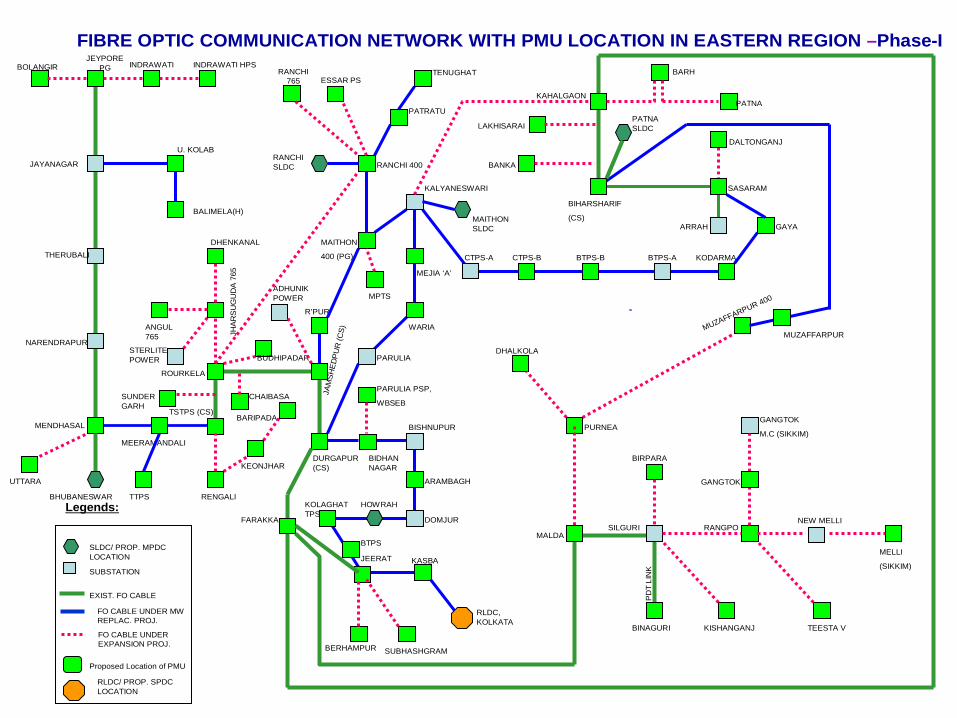
JEYPORE PGBOLANGIR INDRAWATI INDRAWATI HPS
JAYANAGAR
THERUBALI
NARENDRAPUR
MENDHASAL
MEERAMANDALI
TSTPS (CS)
RENGALI
ROURKELA
JHA
RS
UG
UD
A 7
65
ANGUL 765
DHENKANAL
STERLITE POWER
SUNDERGARH
KEONJHAR
BARIPADA
ADHUNIK POWER
JAM
SHED
PUR
(CS)
DURGAPUR (CS)
CHAIBASA
BIDHANNAGAR
BISHNUPUR
ARAMBAGH
DOMJUR
HOWRAHKOLAGHAT TPS
JEERAT KASBA
RLDC, KOLKATA
SUBHASHGRAM
PARULIA PSP,
WBSEB
PARULIA
MEJIA ‘A’
WARIA
KALYANESWARI
MAITHON
400 (PG)
RANCHI 400
R’PUR
MPTS
ESSAR PSRANCHI
765
CTPS-A CTPS-B BTPS-B BTPS-A
BIHARSHARIF
(CS)GAYA
KODARMA
SASARAM
ARRAH
DALTONGANJ
KAHALGAON
FARAKKA
LAKHISARAI
BANKA
BARH
PATNA
MALDA
PURNEA
DHALKOLA
SILGURI RANGPO
BINAGURI
BIRPARA
KISHANGANJ TEESTA V
GANGTOK
GANGTOK
M.C (SIKKIM)
NEW MELLI
MELLI
(SIKKIM)
MUZAFFARPUR 400
BERHAMPURP
DT
LIN
K
UTTARA
FIBRE OPTIC COMMUNICATION NETWORK WITH PMU LOCATION IN EASTERN REGION –Phase-I
BTPS
U. KOLAB
BALIMELA(H)
TTPS
MUZAFFARPUR
PATRATU
TENUGHAT
BUDHIPADAR
BHUBANESWAR
SLDC/ PROP. MPDC LOCATION
SUBSTATION
EXIST. FO CABLE
FO CABLE UNDER EXPANSION PROJ.
Legends:
Proposed Location of PMU
FO CABLE UNDER MW REPLAC. PROJ.
PATNA SLDC
MAITHON SLDC
RANCHI SLDC
RLDC/ PROP. SPDC LOCATION

Super PDC at ERLDC, KOLKATA
URTDSM HIERARCHY – EASTERN REGION
Nodal PDCat S/s
Nodal PDCat S/s
PMUs(202 nos.)
1
4
To NLDC
Remote Console at ERPC
Remote Console at SIKKIM
JHARKHANDMaster PDC
at SLDCs
PMU PMU1 4
TOTAL PMUs = 307 Nos.PHASE 1= 281 Nos.PHASE 2 = 26 Nos.
WEST BENGALMaster PDC
at SLDCs
PMU PMU1 42
ORISSAMaster PDC
at SLDCs
PMU PMU1 22
BIHARMaster PDC
at SLDCs
PMU PMU1 3
CENTRAL STATIONS
DVCMaster PDC
at SLDCs
PMU PMU1 34

APPENDIX North Eastern Region

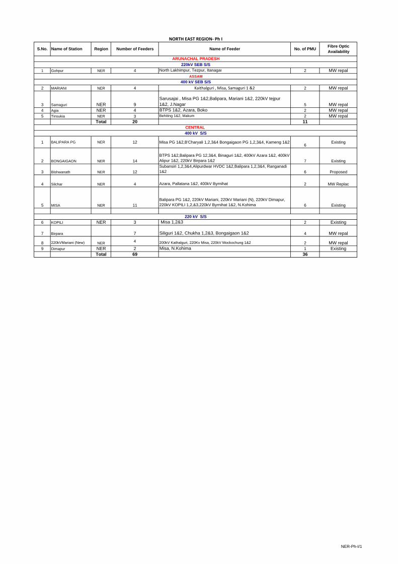
1 Gohpur NER 4 North Lakhimpur, Tezpur, Itanagar 2 MW repal
2 MARIANI NER 4 Kaithalguri , Misa, Samaguri 1 &2 2 MW repal
3 Samaguri NER 9Sarusajai , Misa PG 1&2,Balipara, Mariani 1&2, 220kV tejpur 1&2, J.Nagar 5 MW repal
4 Agia NER 4 BTPS 1&2, Azara, Boko 2 MW repal5 Tinsukia NER 3 Behiting 1&2, Makum 2 MW repal
Total 20 11
1 BALIPARA PG NER 12 Misa PG 1&2,B'Charyali 1,2,3&4 Bongaigaon PG 1,2,3&4, Kameng 1&26
Existing
2 BONGAIGAON NER 14BTPS 1&2,Balipara PG 12,3&4, Binaguri 1&2, 400kV Azara 1&2, 400kV Alipur 1&2, 220kV Birpara 1&2 7 Existing
3 Bishwanath NER 12Subansiri 1,2,3&4,Alipurdwar HVDC 1&2,Balipara 1,2,3&4, Ranganadi 1&2 6 Proposed
4 Silchar NER 4 Azara, Pallatana 1&2, 400kV Byrnihat 2 MW Replac
5 MISA NER 11Balipara PG 1&2, 220kV Mariani, 220kV Mariani (N), 220kV Dimapur, 220kV KOPILI 1,2,&3,220kV Byrnihat 1&2, N.Kohima 6 Existing
6 KOPILI NER 3 Misa 1,2&3 2 Existing
7 Birpara 7 Siliguri 1&2, Chukha 1,2&3, Bongaigaon 1&2 4 MW repal
8 220kVMariani (New) NER 4 200kV Kathalguri, 220Kv Misa, 220kV Mockochung 1&2 2 MW repal9 Dimapur NER 2 Misa, N.Kohima 1 Existing
Total 69 36
CENTRAL
400 kV SEB S/S
NORTH EAST REGION‐ Ph I
Number of Feeders Fibre Optic AvailabilityS.No.
ARUNACHAL PRADESH
Name of Station
400 kV S/S
Name of Feeder
220kV SEB S/S
ASSAM
Region No. of PMU
220 kV S/S
NER-Ph-I/1

1 Subansiri(Lower) NER 4 B'Charyali 1,2,3&4 2 NER-
2 Deomali NER 2 Kathalguri, Miao 1 No3 Miao NER 2 Tezu, Deomali 1 No
Total 8 4
4 Tejpur NER 4 Balipara 1&2, Samaguri 1&2 2 No
5Sarusajai NER 6
Azara, Samaguri , boko, Langpi 1&2, J.nagar 3 No
6 Boko NER 2 Azara, Sarsusajai 1 No7 Longpi NER 2 Sarusajai 1&2 1 No8 Behiating NER 2 Tinsukia 1&2 1 No9 Amingaon NER 2 Rangia 1&2 1 No10 Makum NER 2 Kathalguri, Tinsukia 1 No11 RANGIA NER 3 Amingaon 1&2, Borrnagar 2 No12 Bornagar NER 2 BTPS, Bornagar 1 No13 J.NAGAR NER 2 Samaguri, sarsujai 1 No
Total 27 14
14 PK Bari NER 2 Silchar, Palatana 1 No
15 Mawngap NER 4 N.SHILONG 1&2, Byrnihath 1&2 2 No16 N.shilong NER 2 Mawngap 1&2 1 No
6 3
17 N.KOHIMA 2 Dimapur , Misa 1 No
1 KATHALGURI NER 2220kV Mariani (New),220kVMariani, 220kV Mukum 1 No
2 RANGANADI NER 2 B'Charyali 1&2 1 No3 Khupi NER 2 Tejpur 1&2 1 No4 Pallatana NER 2 Silchar, PKBARI 1 No5 BTPS NER 4 Salakati 1&2, Agia 1&2, 2 No
6 AZARA NER 8
400kV Silichar, 400kV Bongigaon 1&2, 400kV Azara, 220kV Agai 1&2, 220kV Sarusajai, 220kV BOKO 4 No
7 Byrnihat NER 3 400kV Silchar, 400kV Azara, 220kV Mawngap 2 No
8 Khangdong 1 Kopili 1 No9 Mockochung NER 2 220kV Mariani (New) 1&2 1 No
Total 26 14
400 kV SEB S/S
CENTRAL
220 kV S/S
400 kV S/S
MEGAHLYA
NAGALAND
TRIPURA
NORTH EAST REGION‐Ph II
ASSAM
400 kV SEB S/S
220 kV SEB S/S
Number of Feeders
Fibre Optic AvailabilityS.No.
ARUNACHAL PRADESH
Name of Station Region No. of PMUName of Feeder
NER-Ph-II/1

MANIPUR
NAGALAND
TRIPURA
MEGHALAYA
ASSAM
RLDC, SHILLONG
MISA
BALIPARABONGAIGAON
MARIANI
DIMAPUR
SAMAGURI
BTPS
MARIYANI PG
IMPHAL (PG)
KOPILI
KUMARGHAT
AGARTALA
KHLIEHRIAT
GOHPUR
KAHELIPARA SLDC
SARUSAJAI
NEHU, SLDCUMIAM -I
UMIAM-III
KHANDONG
BADARPUR(PG)
AGBPP
KOHIMA
LAKWA NAMRUP
ARUNACHAL PRADESH
MIZORAM
TINSUKIA NAMSAI
AGIA
JIRIBAM
SILCHAR(PG)
ITANAGAR (SLDC)
ITANAGARPG
KOLASIB
AIZAWL(PG)
SRIKONAPAILAPOOL
FIBRE OPTIC COMMUNICATION NETWORK WITH PMU LOCATION IN NORTH EASTERN REGION –Phase-I
BISWANATH CHARIYALI
ALIPURDWAR
SLDC/ PROP. MPDC LOCATION
SUBSTATION
EXIST. FO CABLE
FO CABLE UNDER EXPANSION PROJ.
Legends:
Proposed Location of PMU
FO CABLE UNDER MW REPLAC. PROJ.
RLDC/ PROP. SPDC LOCATION

Super PDC at NERLDC, SHILLONG
URTDSM HIERARCHY – NORTH EASTERN REGION
PMUs(50 nos.)
To NLDC
Remote Console at NERPC
Remote Console at ,TRIPURA,NAGALAND, MANIPUR & MIZORAM
TOTAL PMUs = 86 Nos.PHASE 1= 49 Nos.PHASE 2 = 37 Nos.
Arunachal PradeshMaster PDC
at SLDCs
PMU PMU1 6
PMU
2
CENTRAL STATIONS
,Tripura, Nagaland
MeghalayaMaster PDC
at SLDCs
PMU PMU1 3
ASSAMMaster PDC
at SLDCs
PMU PMU1 25