understanding the use and applications of shock response ...€¦ · of shock response spectrum...
TRANSCRIPT

UNDERSTANDING THE USE AND APPLICATIONS
OF SHOCK RESPONSE SPECTRUM METHOD
CLAUDIE HUTIN DATA PHYSICS (France)
INTRODUCTION
Definition of the Shock Response SpectrumShock tests are performed to verify that a structure or a device can support transient vibrations encountered during its lifein real environmental conditions One of the shock testing formats is the Shock Response Spectrum. Shock ResponseSpectrum (SRS) analysis is, by definition, the maximum response of a series of Single Degree Of Freedom (SDOF)systems of same damping to a given transient signal.
The degree of freedom is defined as the ability to move along or around only one axis. These SDOF systems are selectedas a reference to analyse transient phenomena. Instead of analysing them by FFT process, the SRS uses anothermathematical tool provided by this SDOF reference. Indeed, the FFT algorithm is not suited to non-stationary signals ofshort duration and one states the hypothesis that due to the shortness of the vibrations, the severity can be characterise bytheir maximum effects on the SDOF set.
Equivalence principleEven if the selected reference (SDOF systems) does not represent the equipment to be tested, we can assume that if twodifferent excitations have the same severity (SRS), they will induce equivalent effects on this equipment.This notion of equivalence is at the origin of the using of the SRS because a synthesised pulse can replace a complexexcitation whose severity is the same. Typical applications are: simulation of gunfire, launching, seismic, military aircrafttaking off or landing etc…
SRS testing provides the ability to synthesise a complex waveform that can be applied to electrodynamic orelectrohydraulic exciters in a controlled manner with consistent repeatability avoiding the using of shock machines thatlimit the shape of the excitation pulse. The severity of the test is maximised using SRS techniques.
Advantage of a generalised qualificationThe qualification of equipment is often performed using a record of its specific vibration environment.This procedure must take into account the particular conditions of the records:
q Possible evolutions of some parametersq Uncertainties on the source of excitationq Location of the equipmentq *Etc…
In other words, the time domain transient signal used must not be considered as unique whichever are the conditions ofrecording.
If the environment is characterised by the SRS of the transient it becomes possible to average or envelope differentspectra of different records as to extend the frequency bandwidth or increase the level in particular areas of uncertainties.Then the resulting calculated SRS provides a reference for a global qualification of the equipment, simulating differentconditions of use.
TEST PROCEDURE
The SRS test procedure is very close to any transient testing format; the main difference being that in an SRS test, a timedomain signal is synthesised from the RRS (Required Response Spectrum). We can summarise the procedure as follows:
1) Shock response synthesis2) Calculation of the transfer function of the test facility including amplifier + shaker + table + fixture + structure to be
tested.3) Calculation of one or several drive signals for single or multi axes testing4) Feasibility control to verify that the test facility limits are not exceeded5) Sending and measurement6) Control of the validity of the test by comparing RRS with TRS (Test Response Spectrum) of the control points7) Correction if necessary after each transient sent to the shaker in closed loop
SRS SYNTHESIS
Shock Response Spectrum synthesis is a process where a time history is created whose SRS is exactly the same as therequired one.
In the definition of SRS, only the maximum responses of the SDOF systems are conserved. It appears then that some datais lost in the information. It is easy to understand that the generation of a time domain signal involves the selection ofdifferent unknown parameters.
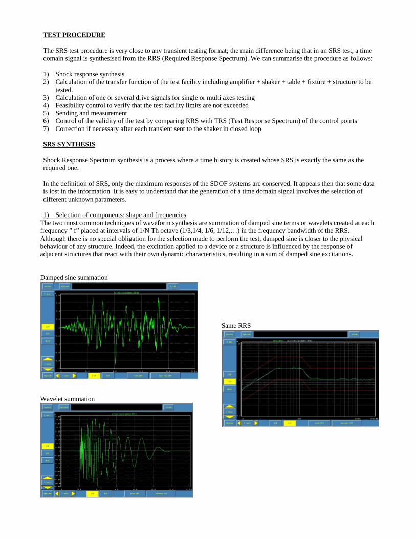
1) Selection of components: shape and frequenciesThe two most common techniques of waveform synthesis are summation of damped sine terms or wavelets created at eachfrequency ” f” placed at intervals of 1/N Th octave (1/3,1/4, 1/6, 1/12,…) in the frequency bandwidth of the RRS.Although there is no special obligation for the selection made to perform the test, damped sine is closer to the physicalbehaviour of any structure. Indeed, the excitation applied to a device or a structure is influenced by the response ofadjacent structures that react with their own dynamic characteristics, resulting in a sum of damped sine excitations.
Damped sine summation
Wavelet summation
Same RRS

2) Delay and number of cycles of componentsThe number of cycles in each term and the placement in time (the delay of appearing within the total time domain windowof synthesis) is user defined.
In fact it is recommended to follow rules of “good sense”:q Wavelet: same delay for all components provides a better accelerogram shape.q Damped sine: the components of heavy weight are placed at the beginning of the time record for a waveform
coherent with natural events.
Heavyweight processing is necessary to create a synthesised time domain record meeting the requirements of the SRS test.Today’s powerful processors help the user in the process of automatically calculating optimal selection of delays and thenumber of cycles to observe the required rules.
The only user decision concerns the total duration of the waveform. Normally this parameter should be part of the testrequirements given automatically with the RRS. If not, the choice is guided by the lowest frequency of the RRS and by thetype of the environment to be simulated.
Another parameter can help in the choice of this duration: it is named ZPA (Zero Period Acceleration). It corresponds tothe asymptotic value of the RRS.and should be also the maximum value of the waveform. When the duration is coherentwith the RRS, one can verify this redundancy.
3) Compensation of the damped sine componentsWavelets defined by acceleration versus time, carefully applied with an odd number of cycles, involve zero velocity anddisplacement at the end of the transient.
On the contrary, damped sine components don’t involve a non-zero value for velocity and displacement at the end of eachsend. It naturally follows that the same must be true for the sum of several components. This particularity can be dangerousfor both the shaker and for the structure under test; some compensation must be performed to avoid this problem. Differenttechniques exist such as:
q Compensating each component of the synthesised waveformq Using the “ZERD” method, which does not excessively modify the physical damped sine shape and leads to a
zero value for both velocity and displacement of the synthesis.
4) Weight of componentsIndividual compensated components are summed and input to the SRS calculation. Then, their amplitudes are adjusted inan iterative manner until the SRS of the synthesised waveform matches the RRS as closely as possible. A technique toachieve good synthesis with a natural waveform shape is to use alternate positive and negative component start polarities.

SRS FEASIBILITY
The ability to perform the entire SRS test is limited by several factors.
1) Dynamics of the RRSA classical problem is encountered when the dynamics of the spectrum (for example, the ratio between the maximum partand the asymptote) is incoherent with the mathematical equation of SRS and especially when it is greater than it should be.
This situation can be due to different processes applied to basic Shock Response Spectrum calculations (average, envelop,increasing of some areas) to define the RRS reference for the test. In this case, the synthesis matches the maximum part ofthe spectrum with a higher level than expected for the asymptote value.
The problem is also encountered when the RRS includes several maximum areas separated by low levels involving a highdynamic range. One must keep in mind that the SRS of only one component defined at one specific frequency, influencesall the adjacent frequencies: even if the synthesis implies zero level for the adjacent components, the spectrum will not bezero and sometimes higher than the requirement.
Introducing negative levels does not solve the problem.
Engineers performing the test most often think that the structure is overtested in this area, but the situation cannot beavoided due to incoherent data.
2) Incoherent parametersAnother current problem encountered concerns the lower frequencies of the RRS. The specification of the lowestfrequency implies a minimum value for the duration of the synthesis (say 1Hz implies at least 1s of duration). If this isincompatible with the test specification, the RRS must be modified to a frequency compatible with the maximum duration.Indeed, this parameter is normally of higher importance because it characterises the type of event to be reproduced.
3) Shaker limits
Another current problem concerns the feasibility of the test in terms of the shaker displacement, velocity and accelerationlimits:
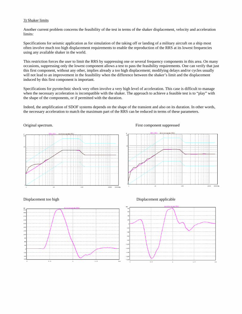
Specifications for seismic application as for simulation of the taking off or landing of a military aircraft on a ship mostoften involve much too high displacement requirements to enable the reproduction of the RRS at its lowest frequenciesusing any available shaker in the world.
This restriction forces the user to limit the RRS by suppressing one or several frequency components in this area. On manyoccasions, suppressing only the lowest component allows a test to pass the feasibility requirements. One can verify that justthis first component, without any other, implies already a too high displacement; modifying delays and/or cycles usuallywill not lead to an improvement in the feasibility when the difference between the shaker’s limit and the displacementinduced by this first component is important.
Specifications for pyrotechnic shock very often involve a very high level of acceleration. This case is difficult to managewhen the necessary acceleration is incompatible with the shaker. The approach to achieve a feasible test is to “play” withthe shape of the components, or if permitted with the duration.
Indeed, the amplification of SDOF systems depends on the shape of the transient and also on its duration. In other words,the necessary acceleration to match the maximum part of the RRS can be reduced in terms of these parameters.
Original spectrum. First component suppressed
Displacement too high Displacement applicable

SRS CLOSED LOOP CONTROL
When the synthesised waveform is performed as its feasibility checking, the resulting signal must be reproduced on thetesting facility with one or several shakers and DOF (Degrees Of Freedom) As for any vibration testing, a pre-test isnecessary to get a first estimation of the transfer function or the transfer function matrix. Then the drive signal(s) can becomputed and reproduced.
If we could assume that the functions obtained during the pre-test are perfect (non-noisy data), and unique (linearbehaviour), we could output the drive signal(s)directly and work in open loop without any correction. In reality the pre-test must be performed at low level first; the obtained functions can be noisy as also different from those of higher levelsand in particular of the nominal level.
For these reasons, control and correction must be performed during the entire test and corrections applied to update thedrive signal(s) after each send.
The control is affected more efficiently if different types of corrections are provided. The correction, which seems themore obvious, involves modifying the drive(s) in terms of the differences between RRS and the obtained TRS becausereally RRS is the reference to match. One must be reminded that the qualification of the structure submitted to a RRS isvaluable if and only if the TRS is greater than the RRS in the entire frequency bandwidth of interest: just one frequencyhaving an amplitude below the RRS leads to a requirement to redo the test.
In practice, other corrections must be provided to manage particular situations.
q The reference might be in the form of a time history corresponding to a captured record or to the designdepartment result of a FE calculation.
q The RRS must be modified because non feasible completely (low frequencies suppressed or digital filteringapplied for example)
In these two cases the correction must be performed in time domain comparing the external or synthesised waveform(s)with the obtained signal(s) at the control points.
q The whole facility and structure behaves non-linearly.
This difficult case must be managed using coefficients of correction, which can be different within the total bandwidth.Sometimes user-defined corrections are applied to force amplification or reduction of the component weights in specificfrequency areas.
CONCLUSION
The technique of SRS testing is very convenient to reproduce complex signals accurately using the power of today’scontrollers, respecting the aspect of a generalised qualification.
Laboratories involved in the seismic qualification of equipment installed in a Nuclear Power Plant have used thistechnique for many years. They have probably been pioneers using SRS, usually in a multi-shaker control manner.
Within the last 10-15 years, other industrial fields have understood the advantages of the technique and have caused thetesting technique to evolve in different directions. Today, the range of applications using SRS is becoming very largeincluding the extremes from seismic qualification (low frequencies, long duration, high displacement), to pyrotechnictesting involving very high frequencies and accelerations and to launch, Gun Fire and aircraft take off and landing.
All are possible if we use flexible tools for synthesis and control to adjust the requirements to make the test feasible.
The needs for SRS testing will continue to evolve: the tendency today being to reproduce as closely as possible, the realconditions of the environment.
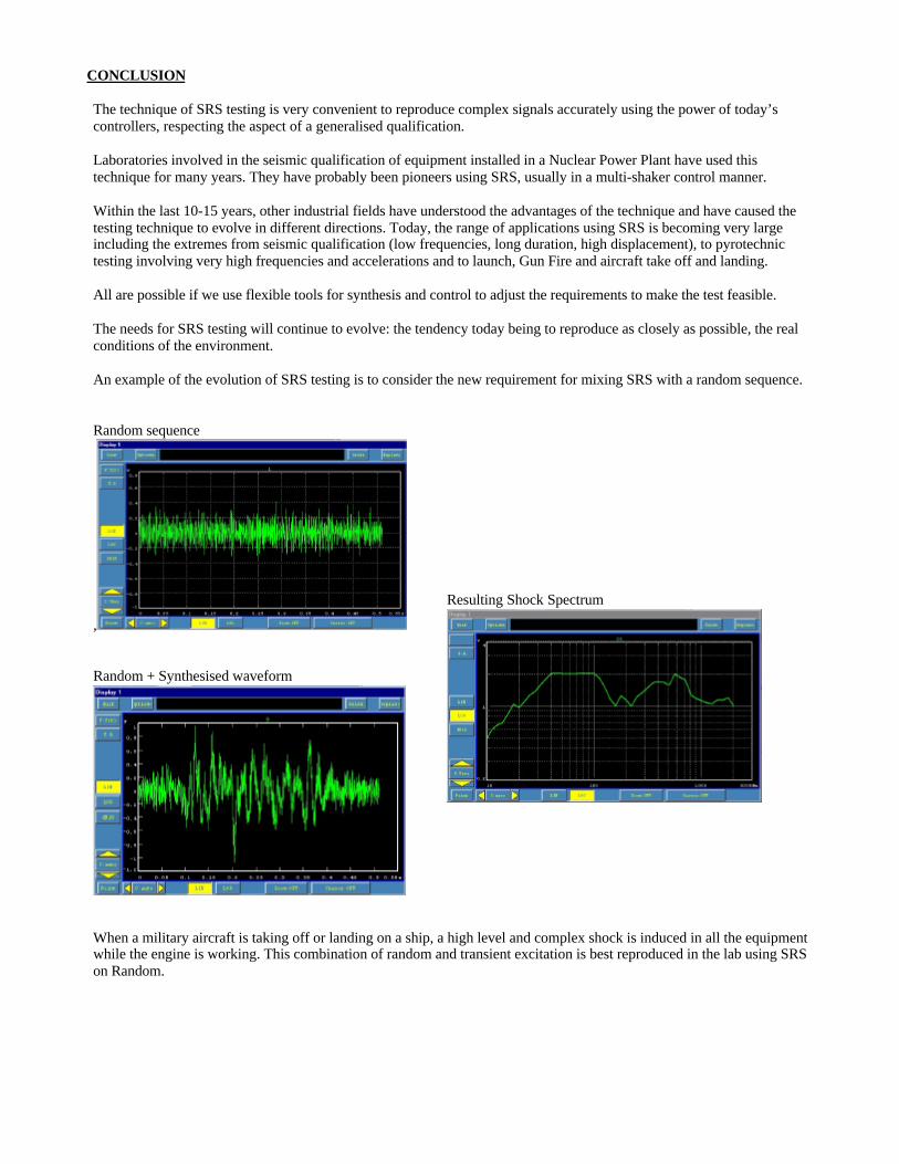
An example of the evolution of SRS testing is to consider the new requirement for mixing SRS with a random sequence.
Random sequence
,
Random + Synthesised waveform
When a military aircraft is taking off or landing on a ship, a high level and complex shock is induced in all the equipmentwhile the engine is working. This combination of random and transient excitation is best reproduced in the lab using SRSon Random.
Resulting Shock Spectrum