understanding 3m™ ultra hard metric (uhm) connectors ... · understanding 3m ultra hard metric...
TRANSCRIPT

Understanding 3M™ Ultra Hard Metric (UHM) Connectors
3M Electronic Solutions Division 3MUHMWEBID_100809
Understanding 3M Ultra Hard Metric (UHM) Connectors“Enabling performance of next generation 2 mm Hard Metric systems”
© 3M 2009. All Rights Reserved.
Webinar Instructions Overview3M Electronic Solutions Division
Scheduled for 30 minutes including a brief Q & A at the end.
Recorded for rebroadcasting at a later date..
All questions need to be sent via chat feature; Incoming phone lines are mutedAll questions need to be sent via chat feature; Incoming phone lines are muted
Selected questions will be answered in Q&A. All other questions will be answered directly via email or a phone call. y p
Promo: Flip™ UltraHD Video Camcorder
Registered participants will need to enter the promotional code: 3MUHM in the Registered participants will need to enter the promotional code: 3MUHM in the field provided in the post webinar survey
** Only Live Event participants eligible for giveaway **
© 3M 2009. All Rights Reserved.
O y e e t pa t c pa ts e g b e o g ea ay
© 3M 2009. All Rights Reserved.

3M Electronic Solutions Division
Understanding 3M™ Ultra Hard Metric (UHM) Connectors“Enabling performance of next generation 2 mm Hard Metric systems”
Jim Vana Jim Vana 3M High Speed Interconnects Applications Engineer
© 3M 2009. All Rights Reserved.© 3M 2009. All Rights Reserved.

2mm Hard Metric (HM)
2mm HM is the industry’s most successful backplane connector system with a strong history. It is adopted by many backplane y g y p y y pstandards…. Right Angle Female Receptacle ( Socket ) Vertical Male
Pin Header
cPCI type backplane (5-row A22, B19, B22)VME 64x backplane (5-row B19) PXI backplane (5-row A22, B22)
J1J1
J2
Backplane
3U Front Plug-in board
Widely available from many connector manufacturers with a vibrant supply chain
4© 3M 2009. All Rights Reserved.
pp y

Crosstalk
One of the major problems in high-speed, high density applications is Crosstalk.
Increased NoiseIncreased Noise at 7 Gbps
TDR
TX
NEXT
FEXT
5© 3M 2009. All Rights Reserved.

The 3MTM Ultra Hard Metric (UHM) Socket Connector
The UHM connector offers the ability yto support high-speed differential signals in 2mm HM systems without costly backplane and daughter card costly backplane and daughter card re-designs.
Th UHM t i hi ld d HM The UHM connector is a shielded HM socket, designed to be intermateable and footprint compatible to HM sockets with superior impedance control and crosstalk reduction.
6© 3M 2009. All Rights Reserved.

Shielding of the 3MTM Ultra Hard Metric (UHM) Socket C tConnector
The UHM socket features i di id l i l hi ldi f individual coaxial shielding of each signal contact. This enables orientation of differential pairs in both rows and columns.
7© 3M 2009. All Rights Reserved.
Horizontal Contact ShieldingVertical Contact Shielding

Performance Improvement by Performance Improvement by Crosstalk reduction…
UHM decreased
noise at 7 Gbps TXFEXT
TDR
NEXT
Increased Noise at 7 Gbps
8© 3M 2009. All Rights Reserved.

Example of a 2mm HM Backplane Connector System with a Example of a 2mm HM Backplane Connector System with a 3MTM Ultra Hard Metric (UHM) Socket Connector
UHM Right Angle Socket / Receptacle
ExternalExternal ground /
shield wipers
Typical 5-row 2 mm HMTypical 5 row 2 mm HM Vertical Header
( +2 ground pins version shown )UHM internal shielding
6th row press fit pins
9
6 row press fit pins
© 3M 2009. All Rights Reserved.

Compatibility to the HM PCB-footprint
The 3MTM Ultra Hard Metric (UHM) Socket Connector’s internal coaxial t hi ldi i t d t d th PCB th h th f/ type shielding is connected to ground on the PCB through the f/z-row. Two options are available: Every odd pin is connected (f) or all pins are connected (f/z).
f /z ( shield)
e
d
c
b
a2 mm
2 mm
10
Edge of Free Board
2 mm
Finished hole 0.550 - 0.650 mm
© 3M 2009. All Rights Reserved.
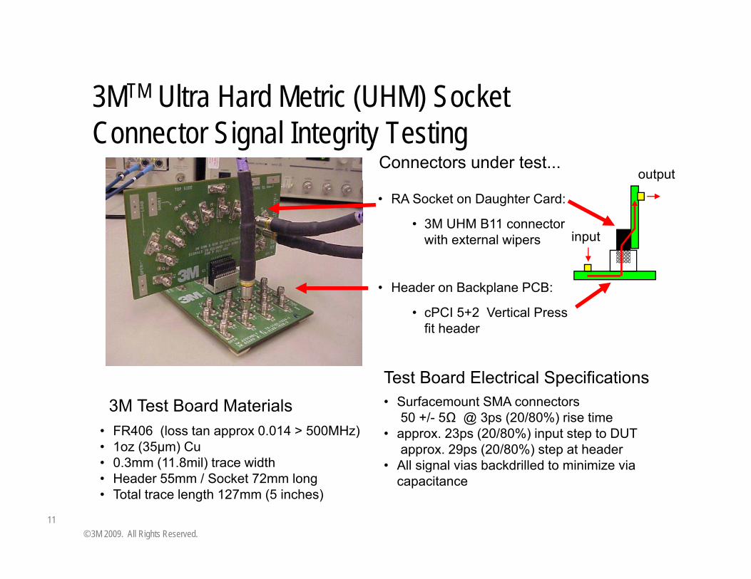
3MTM Ultra Hard Metric (UHM) Socket 3 U a a d e c (U ) Soc eConnector Signal Integrity Testing
Connectors under test...output
• RA Socket on Daughter Card:
• 3M UHM B11 connectorwith external wipers input
p
• Header on Backplane PCB:
• cPCI 5+2 Vertical Press fit header
3
fit header
Surfacemount SMA connectors
Test Board Electrical Specifications3M Test Board Materials
• FR406 (loss tan approx 0.014 > 500MHz)• 1oz (35μm) Cu• 0.3mm (11.8mil) trace width
• Surfacemount SMA connectors50 +/- 5Ω @ 3ps (20/80%) rise time
• approx. 23ps (20/80%) input step to DUT approx. 29ps (20/80%) step at header
• All signal vias backdrilled to minimize via
11
• Header 55mm / Socket 72mm long • Total trace length 127mm (5 inches)
gcapacitance
© 3M 2009. All Rights Reserved.

Row Differential Eye Patterns at 7Gb/s
Recorded Eye Diagrams (including test board) at 7Gb/s show equal performance for all rows with an eye opening of 60% or betterperformance for all rows, with an eye opening of 60% or better
A B C
D E
12© 3M 2009. All Rights Reserved.

Row Differential Impedance ProfileRow Differential Impedance Profile[33ps (20/80) rise time, typical for 5Gb/s]
cPCI Vertical Header mated to the 3MTM Ultra Hard Metric
UHM Row Differential Impedance110
cPCI Vertical Header mated to the 3MTM Ultra Hard Metric (UHM) Right Angle Socket
23 ps95
100
105
110
e (o
hms)
(20%-80%)
80
85
90
Diffe
rent
ial I
mpe
danc
A23B23
UHM Socket 33 ps
70
75
0.50 0.75 1.00 1.25 1.50 1.75 2.00 2.25
Time (ns)
C23D23E23
cPCI Header
Vias
Socket Vias
UHM Socket
33 ps(20%-80%)
13© 3M 2009. All Rights Reserved.
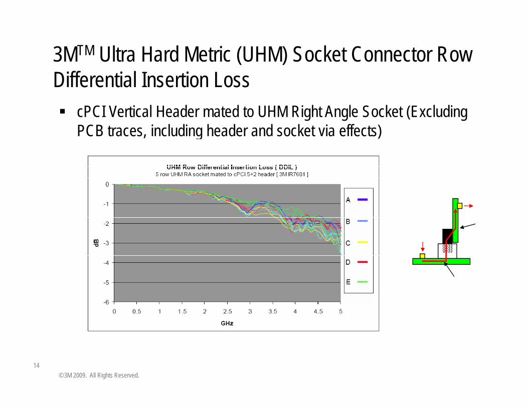
3MTM Ultra Hard Metric (UHM) Socket Connector Row Diff ti l I ti L
cPCI Vertical Header mated to UHM Right Angle Socket (Excluding PCB t i l di h d d k t i ff t )
Differential Insertion Loss
PCB traces, including header and socket via effects)
14© 3M 2009. All Rights Reserved.

TDR Multi-Aggressor CrosstalkTDR Multi Aggressor Crosstalk[33ps (20/80) rise time, typical for 5Gb/s]
Multi-Aggressor Crosstalk
7%
8%
2 NEXT+2 FEXT @33ps
TDR 3%
4%
5%
6%
mai
n C
ross
talk
(%)
TX
NEXT
FEXT
TDR
0%
1%
2%
3%
A B C D ETi
me
Dom
NEXT A B C D E
Row
15© 3M 2009. All Rights Reserved.

3MTM Ultra Hard Metric (UHM) Socket mated to 2mm Hard Metric Header S-parameter Model2mm Hard Metric Header S-parameter Model
A 40-port S-parameter model has been developed for 5 row UHM connector mated to developed for 5 row UHM connector mated to a 5+2 row Hard Metric header.CST Microwave Studio was used to create a model using a bandwidth of 30GHz.model using a bandwidth of 30GHz.The model does not include via effects.
E Row
16© 3M 2009. All Rights Reserved.

VME 64X 6U Application IEC 61076-4-101VME 64X 6U Application IEC 61076-4-101 2 mm Hard Metric Connectors
5 rows x 19 columns (B19)
Problem:Increasing I/O throughput through P0 2 mm Hard Metric connector
Solution:Solution:The 3MTM Ultra Hard Metric (UHM) Socket Connector B19 enabled 4 lanes PCI Express data link through P0 PCI Express data link through P0 between the computer board and the carrier
17© 3M 2009. All Rights Reserved.

cPCI 3U Application – Rear I/OcPCI 3U Application Rear I/OProblem:Increasing I/O throughput through rear I/O plug in boardIncreasing I/O throughput through rear I/O plug in board
Solution:The 3MTM Ultra Hard Metric (UHM) Socket Connector B22 enabled SATA data link through J2 connector
J2Type B 1-22pos Type AB 1 22
rJ2
3U Front Plug-in board 3U Rear Plug-in board
P2
J1
yp p
Type A 1-25pos
1-22pos
P1
Cable I/O option
18© 3M 2009. All Rights Reserved.
p

6U ApplicationProblem:Increasing I/O throughput through rear I/O plug in board
Solution:The 3MTM Ultra Hard Metric (UHM) Socket Connector B22 enabled Multi-Gigabit data links
6U Front Plug-in board 6U Rear Plug-in board
J5
J4
Type B22
Type A25 Type A 25pos
rJ5Type AB 22pos
rJ4
rP5
rP4P4
P5
J2Type B22
J3Type B19 rJ3Type AB 19pos
rP3
P2
P3 Cable I/O
19© 3M 2009. All Rights Reserved.
J1Type A25 P1

3MTM Ultra Hard Metric (UHM) Product family2 mm Hard Metric Standard Connector System
2 mm x 2 mm contact interface5 row: 2 mm x 2 mm PCB footprint (A, B, CL,CR, AB)8 row: 1.5 mm x 2 mm PCB footprint (D, E, FL, FR, DE)
Impedance Matched50 Ω Single Ended50 Ω Single-Ended100 Ω Differential
Low CrosstalkLow Crosstalk<7% Multi aggressor when mated with Unshielded 2mm Header @ Tr=33ps for typical configurations; UHM Socket alone has significantly less Crosstalk
Press-fit sockets are designed to be intermateable to 2mm Hard Metric headers designed to IEC 61076-4-101
20
Press-fit sockets are PCB footprint compatible with 2mm Hard Metric Sockets
© 3M 2009. All Rights Reserved.

Outlook
The 3MTM Ultra Hard Metric (UHM) Socket Connectors, 5-row and 8-row, are available today., y
UHM B22 socket is currently defined in next generation CompactPCI® PICMG 2 30 Standard Draft to support CompactPCI® PICMG 2.30 Standard Draft to support Multi-Gigabit I/O ( 3M work group member )
Work is ongoing on a UHM header for further increased Work is ongoing on a UHM header for further increased system performance with the same design goals and philosophy: to have internal shielding for higher performance and optimum ground connection but still be performance and optimum ground connection, but still be foot print compatible to 5+2 HM headers.
21© 3M 2009. All Rights Reserved.

For more information….
Please visit http://www.3m.com/highspeed for…Please visit http://www.3m.com/highspeed for…
Tech DatasheetsTech Datasheets3D modelsS l dSample ordersWhite papersProduct newsAnd more……..
22© 3M 2009. All Rights Reserved.

Important NoticeThe information we are furnishing you is being provided free of charge and iss g y s g p g sbased on tests performed at 3M laboratory facilities or by our suppliers. Whilewe believe that these test results are reliable, their accuracy or completeness isnot guaranteed. Your results may vary due to differences in test types andconditions. This information is intended for use by persons with the knowledgeand technical skills to analyze, handle and use such information. You mustevaluate and determine whether the product is suitable for your intended
li ti Th f i i f ti i id d “AS IS” I idi thiapplication. The foregoing information is provided “AS-IS”. In providing thisinformation 3M makes no warranties regarding product use or performance,including any implied warranty of merchantability or fitness for a particular use.
For Product warranty information, please see Product Literature.
3M is a trademark of 3M Company.
All other trademarks are the property of their respective owners
23
All other trademarks are the property of their respective owners.
© 3M 2009. All Rights Reserved.

Question & Answer Session3M Electronic Solutions Division
1. What is PICMG ?
2 Wh ill PICMG 2 30 d ft t d d b l d fi l? 2. When will PICMG 2.30 draft standard be released as final?
3. What are expected to be the most common applications driven b ne t generation CompactPCI? by next generation CompactPCI?
4. Can UHM connector be used for Single-end transmission as well ??
24© 3M 2008. All Rights Reserved.

Closing Comments3M Electronic Solutions Division
gLink to webinar recording will be available on 3M’s websites
www 3m com/highspeedwww.3m.com/highspeed
www.3m.com/interconnect
3 /3www.3m.com/3mxpress
Remember to enter the promotional code: 3MUHM in the field provided in the post webinar surveyprovided in the post webinar survey
25© 3M 2008. All Rights Reserved.

3M Electronic Solutions Division
Thank you for your attention.
26© 3M 2009. All Rights Reserved.© 3M 2008. All Rights Reserved.