underground storage of natural gas and co 2 in salt
TRANSCRIPT
Harmonising Rock Engineering and the Environment – Qian & Zhou (eds)© 2012 Taylor & Francis Group, London, ISBN 978-0-415-80444-8
Underground storage of natural gas and CO2 in salt caverns
in deep and ultra-deep water offshore Brazil
A.M. da Costa, C.S. Amaral & E. PoiateR&D Center, Petrobras, Brazil
A.M.B. Pereira
Department of Civil Engineering, Fluminense Federal University (UFF), Rio de Janeiro, Brazil
L.F. Martha, M. Gattass & D. Roehl
Computer Graphics Technology Group, Pontifical Catholic University of Rio de Janeiro (PUC-Rio), Rio de Janeiro, Brazil
ABSTRACT: With the application of new technologies for processing and interpreting seismic data, PETROBRAS, in recentyears, has achieved great success in the discovery of giant oil fields underlying thick layers of rock salt. Due to the mechanicalbehavior of these rocks, subject to the creep phenomenon, it was developed a large research and development project in order todetermine the creep properties of these rocks and the application of computational simulations to predict the behavior of deepwells during the drilling of these layers. If on one hand the salt layers, with thicknesses ranging from 2000m to 5000m, are achallenge in drilling activity, they can be considered in the logistic flow of gas and final destination of CO2. The rock salt hasnegligible porosity when compared to other geomaterials, which guarantees excellent impermeability to most fluids and gases,even under high pressures. Another phenomenon associated with rock salt is the process of self-healing. Taking advantage ofthese physical-chemical and structural properties of rock salt, caverns opened by dissolution in salt domes have been used forstorage of hydrocarbons and other products. Considering the large regional thicknesses and continuity of rock salt overlyingthe presalt reservoirs, PETROBRAS is studying the strategy and technical and economic feasibility for the use of undergroundstorage of natural gas and CO2 in salt caverns. Despite being a technology already dominated worldwide is unprecedented, theoffshore application in deep and ultra-deep water.
Subject: Underground storage
Keywords: rock caverns, mine design, numerical modeling, stability analysis, oil reservoir
1 INTRODUCTION
The rock salt has negligible porosity when compared to othergeomaterials, which ensures excellent sealing to most fluidsand gases, even under high pressures. Rock salt is also subjectto the phenomenon of visco-plastic creep deformation whichdevelops in the time domain the relaxation of the deviatoric orshear stresses, to the condition of a steady-state equilibriumwith constant creep strain rate and can tolerate high levelsof strain without develop structural damage of its mineralskeleton.
This phenomenon can be observed in nature in the sedi-mentary layers intercepted by salt domes or other structuresassociated with the natural movement of salt. Another phe-nomenon associated with the salt rock is the process ofself-healing, where cracks and faults are self-healedwith time.Taking advantage of these physical-chemical and structuralproperties of rock salt, caverns developed by solution min-ing in salt domes have been used for storage of hydrocarbonsand other products. Conventional underground salt mines arealso used for final destination of radioactive material (nuclearwaste).
Currently there are about 1600 caverns opened by solu-tion mining in North America for this purpose and inapproximately equal number in Europe. Among them the
most important hydrocarbon underground storage is the“Strategic Petroleum Reserve, the largest strategic petroleumreserve in the world in the Gulf of Mexico, United States,where is stored 727 million barrels of crude oil in 60 cavesopen by solution mining, 600m high and 60m in diameter.Currently this project is being expanded to 1 billion barrelsof oil.
Considering the great regional thickness and continuity ofrock salt in the Santos Basin oil province in Brazil it is understudy the strategy and technical and economical feasibilityevaluation for the use of underground offshore caverns openedby solution mining, Figure 1.
The Santos Basin, offshore southeast Brazil, is one of theBrazilian basins that is receiving considerable industry atten-tion nowadays, with the discovery of the giant oil fields knownas Pre-Salt reservoirs.
The Pre-Salt reservoirs in Santos basin are located in waterdepth varying from 150m up to 2200m. To reach the Pre-Salt reservoirs located in deep water it is necessary to drillthrough 2000m of salt rock, mainly halite, and in someplaces, tachyhydrite (CaCl2·2MgCl2·12H2O), and carnallite(KCl·MgCl2·6H2O) intercalations are found.
Despite being a technology already dominated worldwideis unprecedented its offshore application in deepwater andultra-deep waters.
1659
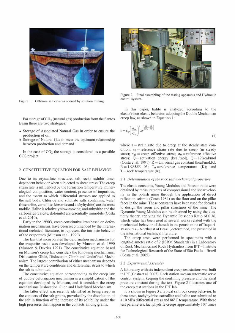
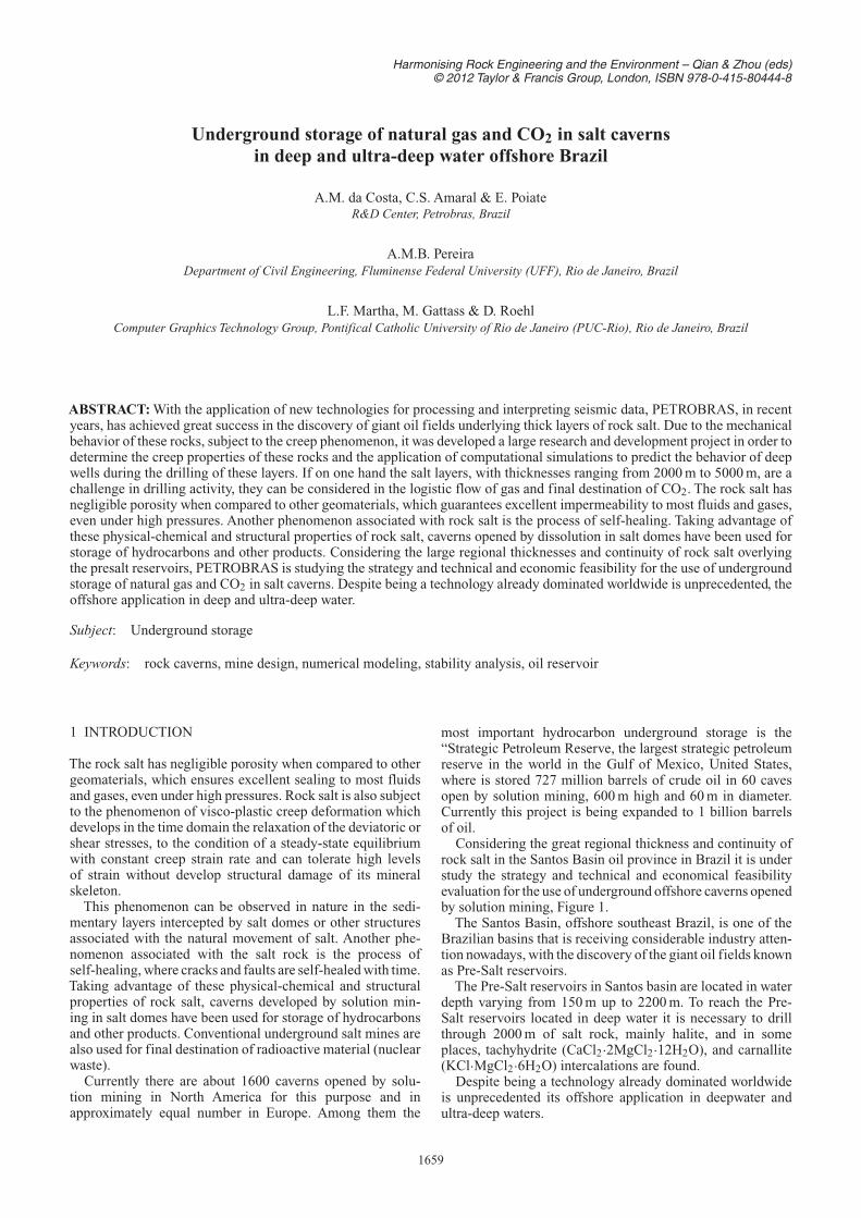
Figure 1. Offshore salt caverns opened by solution mining.
For storage of CH4 (natural gas) production from the SantosBasin there are two strategies:
• Storage of Associated Natural Gas in order to ensure theproduction of oil.
• Storage of Natural Gas to meet the optimum relationshipbetween production and demand.
In the case of CO2 the storage is considered as a possibleCCS project.
2 CONSTITUTIVE EQUATION FOR SALT BEHAVIOR
Due to its crystalline structure, salt rocks exhibit time-dependent behavior when subjected to shear stress. The creepstrain rate is influenced by the formation temperature, miner-alogical composition, water content, presence of impurities,and the extent to which differential stresses are applied tothe salt body. Chloride and sulphate salts containing water(bischofite, carnallite, kieserite and tachyhydrite) are themostmobile.Halite is relatively slow-moving, and anhydrite and thecarbonates (calcite, dolomite) are essentially immobile (Costaet al. 2010).
Early in the 1990’s, creep constitutive laws based on defor-mation mechanisms, have been recommended by the interna-tional technical literature, to represent the intrinsic behaviorof the evaporates (Munson et al. 1990).
The law that incorporates the deformation mechanisms forthe evaporite rocks was developed by Munson et al. 1990(Munson & Devries 1991). The constitutive equation basedon Munson’s creep law considers the following mechanisms:Dislocation Glide, Dislocation Climb and Undefined Mech-anism. The largest contribution of either mechanism dependson the temperature conditions and differential stress to whichthe salt is submitted.
The constitutive equation corresponding to the creep lawof double deformation mechanism is a simplification of theequation developed by Munson, and it considers the creepmechanisms Dislocation Glide and Undefined Mechanism.
The latter effect was recently identified as being creep inthe contacts of the salt grains, provoked by the dissolution ofthe salt in function of the increase of its solubility under thehigh pressures that happen in the contacts among grains.
Figure 2. Final assembling of the testing apparatus and Hydrauliccontrol system.
In this paper, halite is analyzed according to theelasto/visco-elastic behavior, adopting theDoubleMechanismcreep law, as shown in Equation 1:
where ε = strain rate due to creep at the steady state con-dition; ε0 = reference strain rate due to creep (in steadystate); εef = creep effective stress; σ0 = reference effectivestress; Q= activation energy (kcal/mol), Q= 12 kcal/mol(Costa et al. 1991); R=Universal gas constant (kcal/mol.K),R= 1.9858E−03; T0 = reference temperature (K); andT= rock temperature (K).
2.1 Determination of the rock salt mechanical properties
The elastic constants, Young Modulus and Poisson ratio wereobtained by measurements of compressional and shear veloc-ity in the potash mine through the application of directreflection seismic (Costa 1984) on the floor and on the pillarfaces in the mine. These constants have been used for decadesto design the room and pillar structures of the mine. TheDynamic Young Modulus can be obtained by using the elas-ticity theory, applying the Dynamic Poisson’s Ratio of 0.36,which value has been used in several works related with themechanical behavior of the salt in the potash mine of Taquari-Vassouras – Northeast of Brazil, determined, and presented inthe international technical literature.
The creep tests were performed in specimens with alength/diameter ratio of 2 (ISRM Standards) in a Laboratoryof Rock Mechanics and Rock Hydraulics from IPT – Institutefor Technological Research of the State of São Paulo – Brazil(Costa et al. 2005).
2.2 Experimental Assembly
A laboratory with six independent creep test stations was builtin IPT (Costa et al. 2005). Each station uses an automatic servocontrol system, keeping the confining pressure and the axialpressure constant during the test. Figure 2 illustrates one ofthe creep test stations in the IPT lab.
It is shown in Figure 3 a typical salt rock creep behavior. Inthese tests, tachyhydrite, carnallite and halite are submitted toa 10MPa differential stress and 86◦C temperature.With thesetest parameters, tachyhydrite creeps approximately 107 times
1660
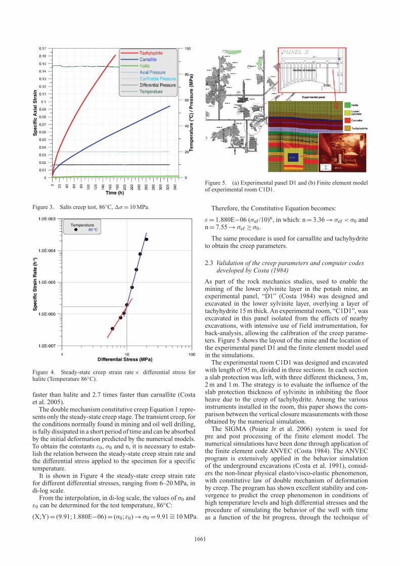
Figure 3. Salts creep test, 86◦C, 1σ = 10MPa.
Figure 4. Steady-state creep strain rate× differential stress forhalite (Temperature 86◦C).
faster than halite and 2.7 times faster than carnallite (Costaet al. 2005).
The double mechanism constitutive creep Equation 1 repre-sents only the steady-state creep stage.The transient creep, forthe conditions normally found in mining and oil well drilling,is fully dissipated in a short period of time and can be absorbedby the initial deformation predicted by the numerical models.To obtain the constants ε0, σ0 and n, it is necessary to estab-lish the relation between the steady-state creep strain rate andthe differential stress applied to the specimen for a specifictemperature.
It is shown in Figure 4 the steady-state creep strain ratefor different differential stresses, ranging from 6–20MPa, indi-log scale.
From the interpolation, in di-log scale, the values of σ0 andε0 can be determined for the test temperature, 86◦C:
(X;Y)= (9.91; 1.880E−06)= (σ0; ε0)→ σ0 = 9.91∼= 10MPa.
Figure 5. (a) Experimental panel D1 and (b) Finite element modelof experimental room C1D1.
Therefore, the Constitutive Equation becomes:
ε = 1.880E−06 (σef /10)n, in which: n= 3.36→ σef < σ0 and
n= 7.55→ σef ≥ σ0.
The same procedure is used for carnallite and tachyhydriteto obtain the creep parameters.
2.3 Validation of the creep parameters and computer codesdeveloped by Costa (1984)
As part of the rock mechanics studies, used to enable themining of the lower sylvinite layer in the potash mine, anexperimental panel, “D1” (Costa 1984) was designed andexcavated in the lower sylvinite layer, overlying a layer oftachyhydrite 15m thick.An experimental room, “C1D1”, wasexcavated in this panel isolated from the effects of nearbyexcavations, with intensive use of field instrumentation, forback-analysis, allowing the calibration of the creep parame-ters. Figure 5 shows the layout of the mine and the location ofthe experimental panel D1 and the finite element model usedin the simulations.
The experimental room C1D1 was designed and excavatedwith length of 95m, divided in three sections. In each sectiona slab protection was left, with three different thickness, 3m,2m and 1m. The strategy is to evaluate the influence of theslab protection thickness of sylvinite in inhibiting the floorheave due to the creep of tachyhydrite. Among the variousinstruments installed in the room, this paper shows the com-parison between the vertical closure measurements with thoseobtained by the numerical simulation.
The SIGMA (Poiate Jr et al. 2006) system is used forpre and post processing of the finite element model. Thenumerical simulations have been done through application ofthe finite element code ANVEC (Costa 1984). The ANVECprogram is extensively applied in the behavior simulationof the underground excavations (Costa et al. 1991), consid-ers the non-linear physical elasto/visco-elastic phenomenon,with constitutive law of double mechanism of deformationby creep. The program has shown excellent stability and con-vergence to predict the creep phenomenon in conditions ofhigh temperature levels and high differential stresses and theprocedure of simulating the behavior of the well with timeas a function of the bit progress, through the technique of
1661
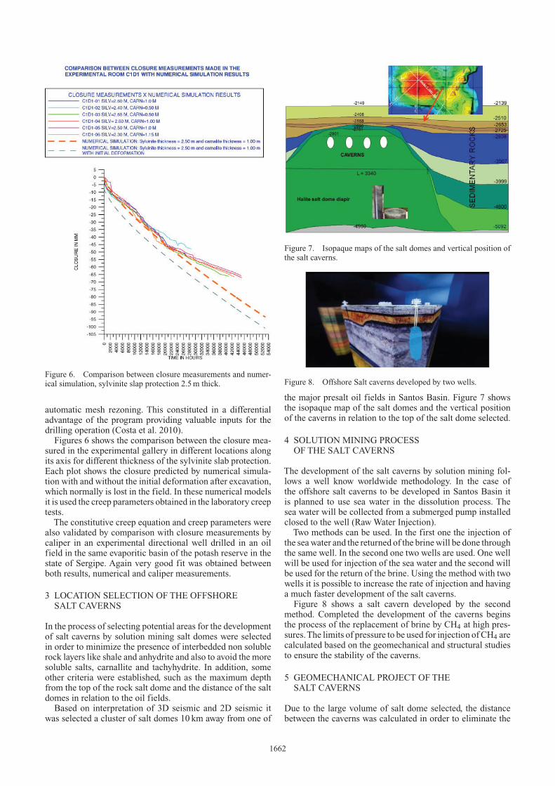
Figure 6. Comparison between closure measurements and numer-ical simulation, sylvinite slap protection 2.5m thick.
automatic mesh rezoning. This constituted in a differentialadvantage of the program providing valuable inputs for thedrilling operation (Costa et al. 2010).
Figures 6 shows the comparison between the closure mea-sured in the experimental gallery in different locations alongits axis for different thickness of the sylvinite slab protection.Each plot shows the closure predicted by numerical simula-tion with and without the initial deformation after excavation,which normally is lost in the field. In these numerical modelsit is used the creep parameters obtained in the laboratory creeptests.
The constitutive creep equation and creep parameters werealso validated by comparison with closure measurements bycaliper in an experimental directional well drilled in an oilfield in the same evaporitic basin of the potash reserve in thestate of Sergipe. Again very good fit was obtained betweenboth results, numerical and caliper measurements.
3 LOCATION SELECTION OF THE OFFSHORESALT CAVERNS
In the process of selecting potential areas for the developmentof salt caverns by solution mining salt domes were selectedin order to minimize the presence of interbedded non solublerock layers like shale and anhydrite and also to avoid the moresoluble salts, carnallite and tachyhydrite. In addition, someother criteria were established, such as the maximum depthfrom the top of the rock salt dome and the distance of the saltdomes in relation to the oil fields.
Based on interpretation of 3D seismic and 2D seismic itwas selected a cluster of salt domes 10 km away from one of
Figure 7. Isopaque maps of the salt domes and vertical position ofthe salt caverns.
Figure 8. Offshore Salt caverns developed by two wells.
the major presalt oil fields in Santos Basin. Figure 7 showsthe isopaque map of the salt domes and the vertical positionof the caverns in relation to the top of the salt dome selected.
4 SOLUTION MINING PROCESSOF THE SALT CAVERNS
The development of the salt caverns by solution mining fol-lows a well know worldwide methodology. In the case ofthe offshore salt caverns to be developed in Santos Basin itis planned to use sea water in the dissolution process. Thesea water will be collected from a submerged pump installedclosed to the well (RawWater Injection).
Two methods can be used. In the first one the injection ofthe seawater and the returned of the brinewill be done throughthe same well. In the second one two wells are used. One wellwill be used for injection of the sea water and the second willbe used for the return of the brine. Using the method with twowells it is possible to increase the rate of injection and havinga much faster development of the salt caverns.
Figure 8 shows a salt cavern developed by the secondmethod. Completed the development of the caverns beginsthe process of the replacement of brine by CH4 at high pres-sures.The limits of pressure to be used for injection of CH4 arecalculated based on the geomechanical and structural studiesto ensure the stability of the caverns.
5 GEOMECHANICAL PROJECT OF THESALT CAVERNS
Due to the large volume of salt dome selected, the distancebetween the caverns was calculated in order to eliminate the
1662
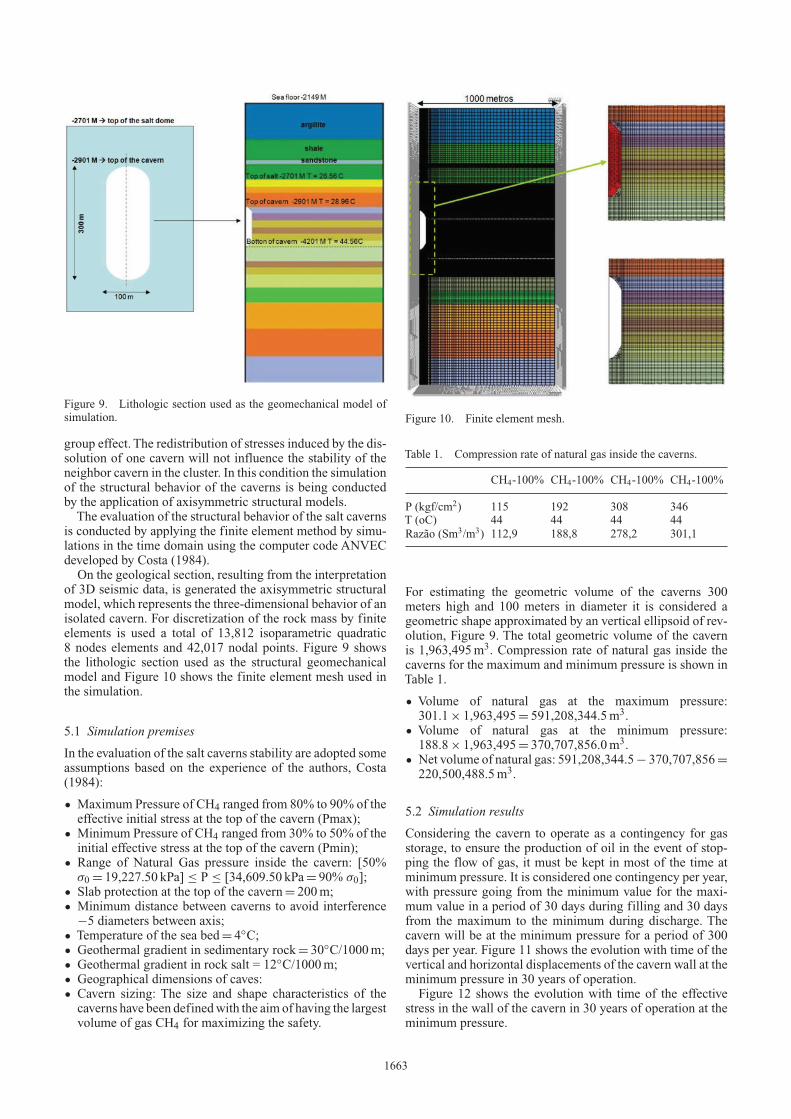
Figure 9. Lithologic section used as the geomechanical model ofsimulation.
group effect. The redistribution of stresses induced by the dis-solution of one cavern will not influence the stability of theneighbor cavern in the cluster. In this condition the simulationof the structural behavior of the caverns is being conductedby the application of axisymmetric structural models.
The evaluation of the structural behavior of the salt cavernsis conducted by applying the finite element method by simu-lations in the time domain using the computer code ANVECdeveloped by Costa (1984).
On the geological section, resulting from the interpretationof 3D seismic data, is generated the axisymmetric structuralmodel, which represents the three-dimensional behavior of anisolated cavern. For discretization of the rock mass by finiteelements is used a total of 13,812 isoparametric quadratic8 nodes elements and 42,017 nodal points. Figure 9 showsthe lithologic section used as the structural geomechanicalmodel and Figure 10 shows the finite element mesh used inthe simulation.
5.1 Simulation premises
In the evaluation of the salt caverns stability are adopted someassumptions based on the experience of the authors, Costa(1984):
• Maximum Pressure of CH4 ranged from 80% to 90% of theeffective initial stress at the top of the cavern (Pmax);
• Minimum Pressure of CH4 ranged from 30% to 50% of theinitial effective stress at the top of the cavern (Pmin);
• Range of Natural Gas pressure inside the cavern: [50%σ0 = 19,227.50 kPa] ≤ P ≤ [34,609.50 kPa= 90% σ0];
• Slab protection at the top of the cavern= 200m;• Minimum distance between caverns to avoid interference
−5 diameters between axis;• Temperature of the sea bed= 4◦C;• Geothermal gradient in sedimentary rock= 30◦C/1000m;• Geothermal gradient in rock salt = 12◦C/1000m;• Geographical dimensions of caves:• Cavern sizing: The size and shape characteristics of the
caverns have been definedwith the aim of having the largestvolume of gas CH4 for maximizing the safety.
Figure 10. Finite element mesh.
Table 1. Compression rate of natural gas inside the caverns.
CH4-100% CH4-100% CH4-100% CH4-100%
P (kgf/cm2) 115 192 308 346T (oC) 44 44 44 44
Razão (Sm3/m3) 112,9 188,8 278,2 301,1
For estimating the geometric volume of the caverns 300meters high and 100 meters in diameter it is considered ageometric shape approximated by an vertical ellipsoid of rev-olution, Figure 9. The total geometric volume of the cavernis 1,963,495m3. Compression rate of natural gas inside thecaverns for the maximum and minimum pressure is shown inTable 1.
• Volume of natural gas at the maximum pressure:301.1× 1,963,495= 591,208,344.5m3.
• Volume of natural gas at the minimum pressure:188.8× 1,963,495= 370,707,856.0m3.
• Net volume of natural gas: 591,208,344.5− 370,707,856=
220,500,488.5m3.
5.2 Simulation results
Considering the cavern to operate as a contingency for gasstorage, to ensure the production of oil in the event of stop-ping the flow of gas, it must be kept in most of the time atminimum pressure. It is considered one contingency per year,with pressure going from the minimum value for the maxi-mum value in a period of 30 days during filling and 30 daysfrom the maximum to the minimum during discharge. Thecavern will be at the minimum pressure for a period of 300days per year. Figure 11 shows the evolution with time of thevertical and horizontal displacements of the cavern wall at theminimum pressure in 30 years of operation.
Figure 12 shows the evolution with time of the effectivestress in the wall of the cavern in 30 years of operation at theminimum pressure.
1663
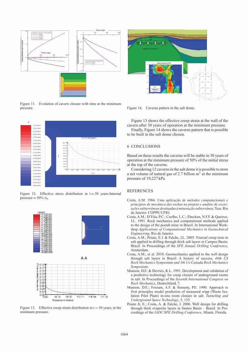
Figure 11. Evolution of cavern closure with time at the minimumpressure.
Figure 12. Effective stress distribution in t= 30 years-Internalpressure= 50% σ0.
Figure 13. Effective creep strain distribution in t= 30 years, at theminimum pressure.
Figure 14. Caverns pattern in the salt dome.
Figure 13 shows the effective creep strain at the wall of thecavern after 30 years of operation at the minimum pressure.
Finally, Figure 14 shows the caverns pattern that is possibleto be built in the salt dome chosen.
6 CONCLUSIONS
Based on these results the caverns will be stable in 30 years ofoperation at the minimum pressure of 50% of the initial stressat the top of the caverns.
Considering 12 caverns in the salt dome it is possible to storea net volume of natural gas of 2.7 billion m3 at the minimumpressure of 19,227 kPa.
REFERENCES
Costa, A.M. 1984. Uma aplicação de métodos computacionais eprincípios de mecânica das rochas no projeto e análise de escav-ações subterrâneas destinadas àmineração subterrânea.Tese.Riode Janeiro: COPPE/UFRJ.
Costa, A.M.; D’Elia, P.C.; Coelho, L.C.; Ebecken, N.F.F. & Queiroz,J.L. 1991. Rock mechanics and computational methods appliedto the design of the postah mine in Brazil. In International Work-shop Applications of Computational Mechanics in GeotechnicalEngineering, Rio de Janeiro.
Costa, A.M.; Poiate, E.J. & Falcão, J.L. 2005. Triaxial creep tests insalt applied in drilling through thick salt layers in Campos Basin-Brazil. In Proceedings of the SPE Annual Drilling Conference,Amsterdam.
Costa, A.M.; et al. 2010. Geomechanics applied to the well designthrough salt layers in Brazil: A history of success, 44th USRock Mechanics Symposium and 5th Us-Canada Rock MechanicsSymposium.
Munson, D.E. & Devries, K.L. 1991. Development and validation ofa predictive technology for creep closure of underground roomsin salt. In Proceedings of the Seventh International Congress onRock Mechanics, Deutschland, 7.
Munson, D.E.; Fossum, A.F. & Senseny, P.E. 1990. Approach tofirst principles model prediction of measured wipp (Waste Iso-lation Pilot Plant) in-situ room closure in salt. Tunneling andUnderground Space Technology, 5, 135.
Poiate Jr, E.; Costa, A. & Falcão, J. 2006. Well design for drillingthrough thick evaporite layers in Santos Basin – Brazil. In Pro-ceedings of the IADC/SPE Drilling Conference, Miami, Florida.
1664