unbalanced fault analysisraelshat/courses_dr/eleb7.old/newnotes... · unbalanced faults unbalance...
TRANSCRIPT
ELE B7 Power Systems ELE B7 Power Systems Engineering Engineering
Unbalanced Fault Analysis
Slide # 1
Unbalanced Fault Analysis
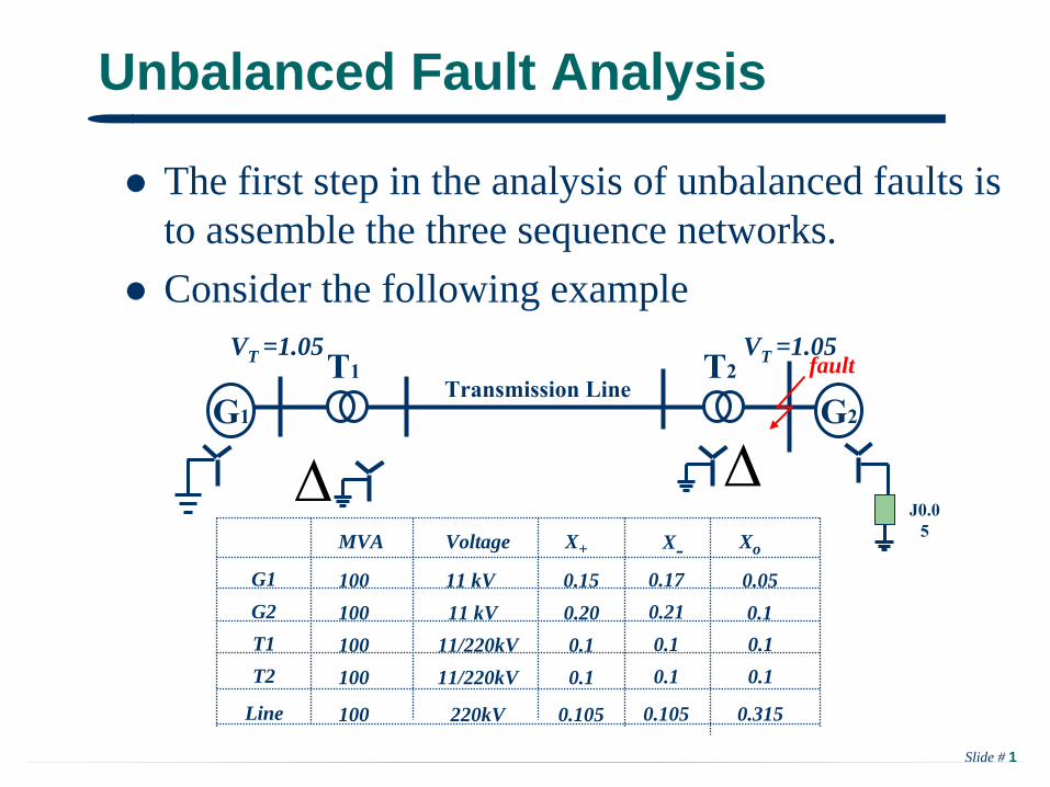
The first step in the analysis of unbalanced faults is to assemble the three sequence networks.
Consider the following example
T1
G1
T2 Transmission Line
VT =1.05
G2
J0.0
5
fault
G1
MVA X+Voltage X- Xo
100 0.1511 kV 0.05G2 100 0.2011 kV 0.1T1 100 0.111/220kVT2 100 0.111/220kV
Line 100 0.105220kV
0.170.21
0.10.1
0.315
0.10.1
0.105
VT =1.05
Slide # 2
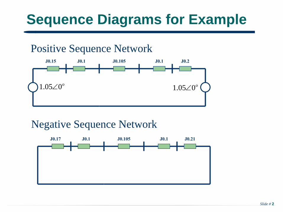
Sequence Diagrams for Example
Positive Sequence Network
Negative Sequence Network
J0.2J0.1J0.15 J0.1 J0.105
o005.1 o005.1
J0.21J0.1J0.17 J0.1 J0.105
Slide # 3
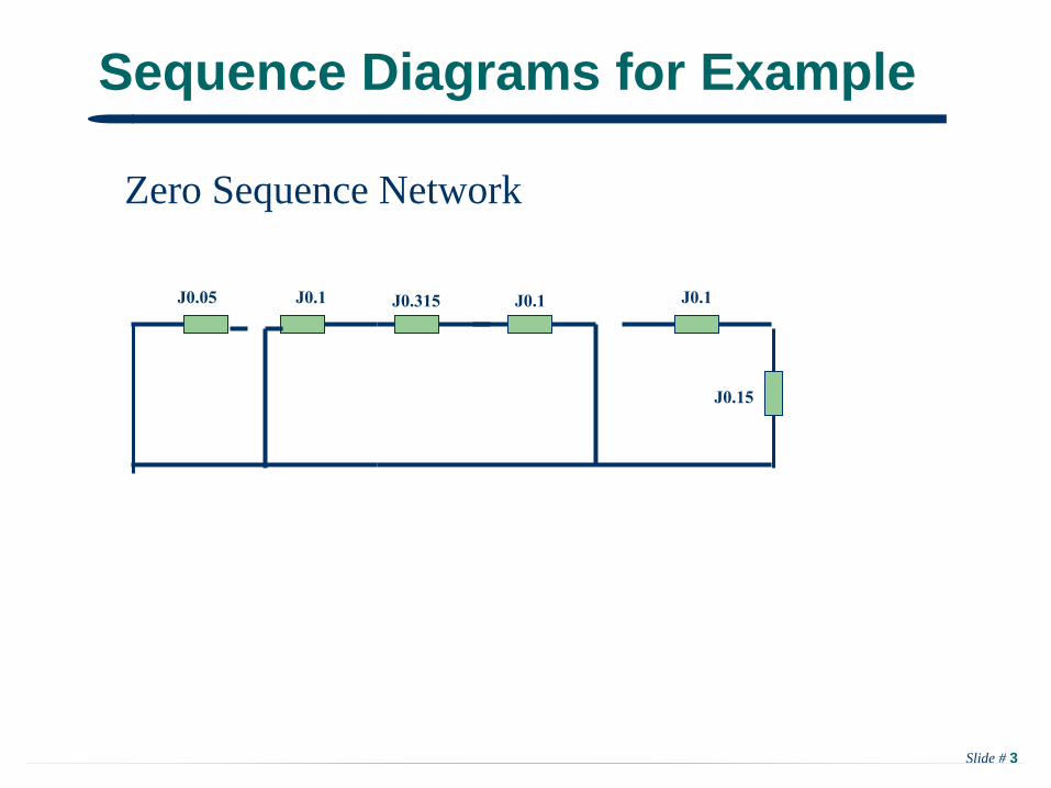
Sequence Diagrams for Example
Zero Sequence Network
J0.1J0.1
J0.15
J0.1 J0.315J0.05
Slide # 4
Create Thevenin Equivalents
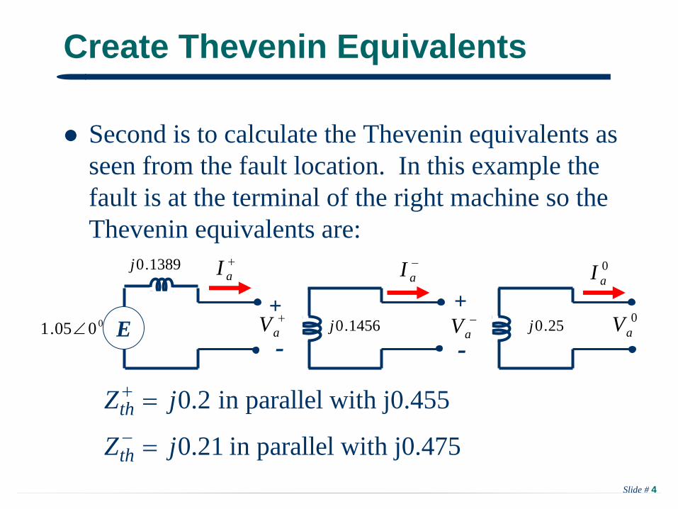
Second is to calculate the Thevenin equivalents as seen from the fault location. In this example the fault is at the terminal of the right machine so the Thevenin equivalents are:
0.2 in parallel with j0.455
0.21 in parallel with j0.475th
th
Z j
Z j
aI
E
1389.0j
0005.1
aV+
-
aI
aV
+
-0
aV
0aI
25.0j1456.0j
Slide # 5
Single Line-to-Ground (SLG) Faults
Unbalanced faults unbalance the network, but only at the fault location. This causes a coupling of the sequence networks. How the sequence networks are coupled depends upon the fault type. We’ll derive these relationships for several common faults.
With a SLG fault only one phase has non-zero fault current -- we’ll assume it is phase A.
Slide # 6
SLG Faults, cont’d
bV
bI
cV
cIaVaI
fZ
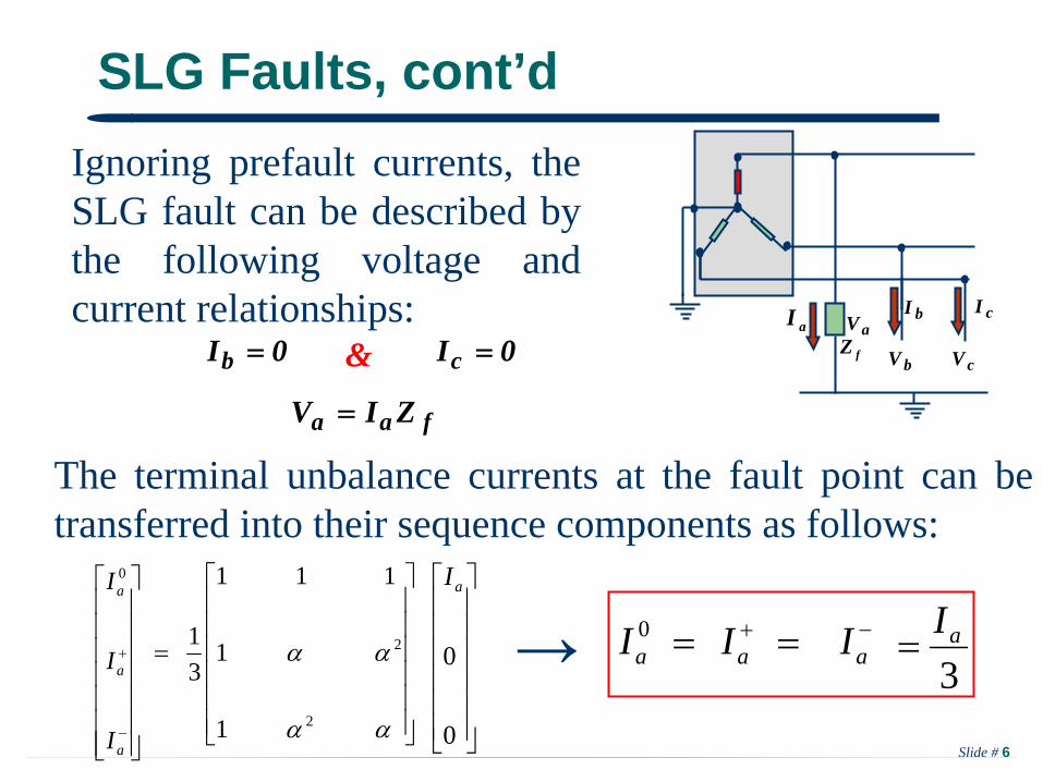
Ignoring prefault currents, the SLG fault can be described by the following voltage and current relationships:
0Ib 0Ic
faa ZIV
&
The terminal unbalance currents at the fault point can be transferred into their sequence components as follows:
0
0
aI
2
2
1
1
111
31
a
a
a
I
I
I 0
0aI
aI aI
3aI
→
Slide # 7
SLG Faults, cont’d
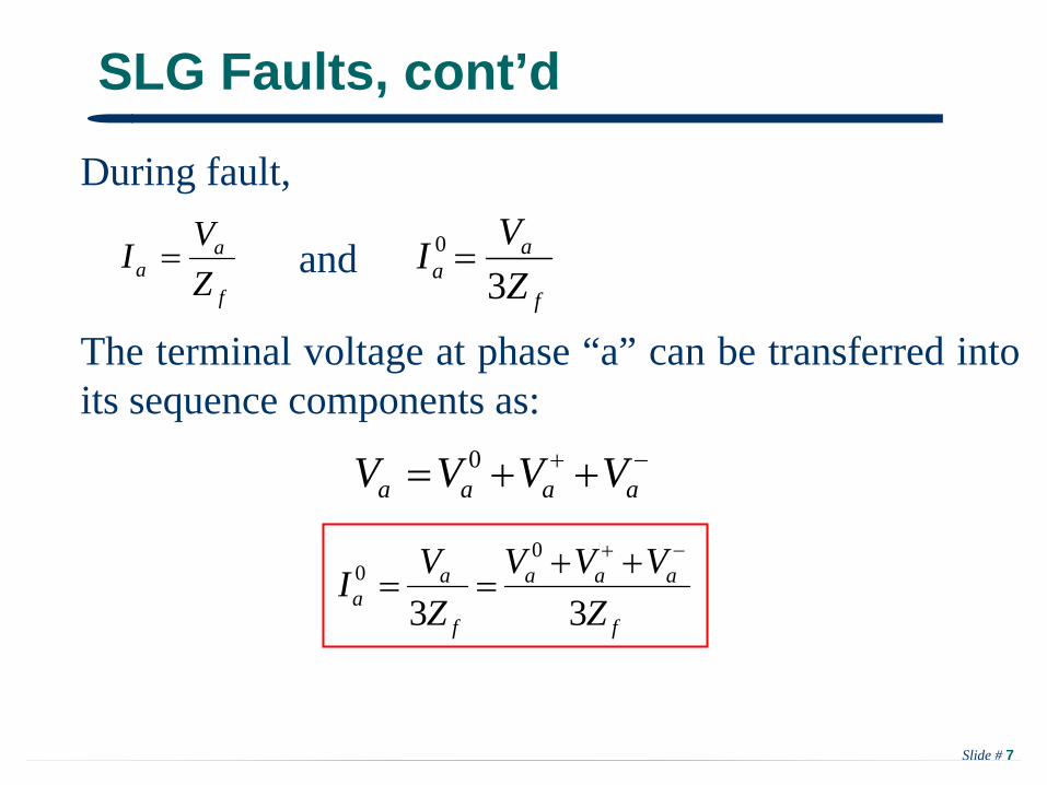
During fault,
f
aa Z
VI f
aa Z
VI3
0 and
f
aaa
f
aa Z
VVVZVI
33
00
aaaa VVVV 0
The terminal voltage at phase “a” can be transferred into its sequence components as:
Slide # 8
SLG Faults, cont’d
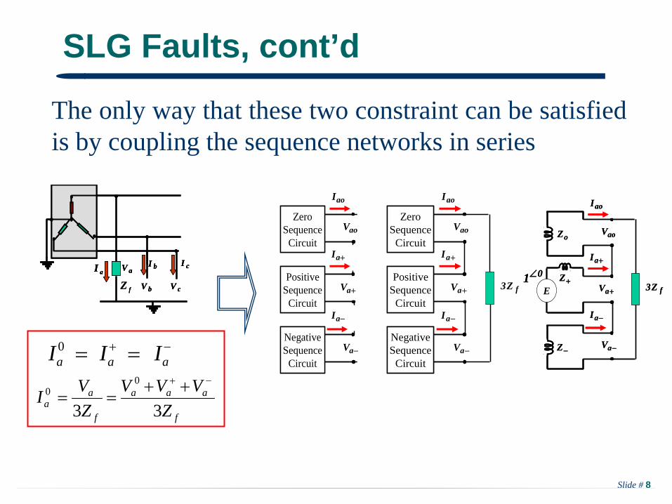
The only way that these two constraint can be satisfied is by coupling the sequence networks in series
aoI
ZeroSequence
Circuit
ZeroSequence
Circuit
NegativeSequence
Circuit
NegativeSequence
Circuit
PositiveSequence
Circuit
PositiveSequence
Circuit
aI
aI
aV
aV
aoV
fZ3
aoI
aI
aI
aV
aV
aoV
fZ3E
Z
Z
oZ
01
aoI
aI
aI
aV
aV
aoV
fZ3E
Z
Z
oZ
01bV
bI
cV
cIaVaI
fZ bV
bI
cV
cIaVaI
bV
bI
cV
cIaVaI
fZ
aoI
ZeroSequence
Circuit
ZeroSequence
Circuit
NegativeSequence
Circuit
NegativeSequence
Circuit
PositiveSequence
Circuit
PositiveSequence
Circuit
aI
aI
aV
aV
aoV
0aI
aI aI
f
aaa
f
aa Z
VVVZVI
33
00
Slide # 9
Example:
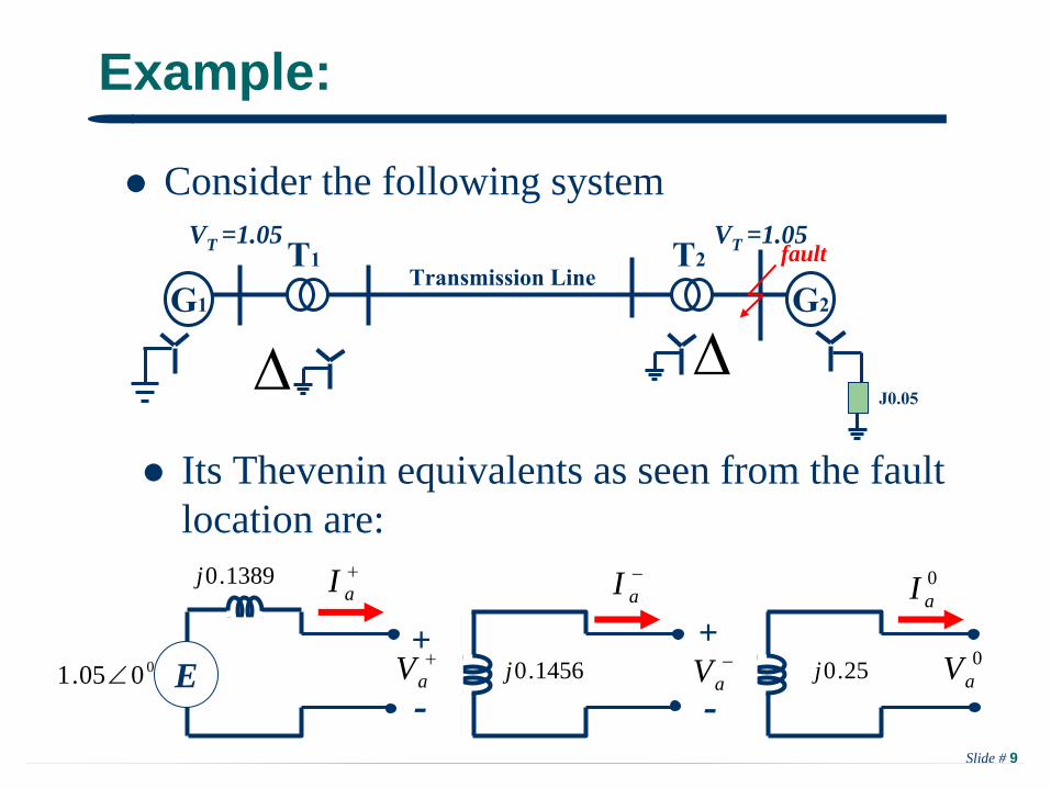
Consider the following system
T1
G1
T2 Transmission Line
VT =1.05
G2
J0.05
fault
VT =1.05
Its Thevenin equivalents as seen from the fault location are:
aI
E
1389.0j
0005.1
aV+
-
aI
aV
+
-0
aV
0aI
25.0j1456.0j
Slide # 10
Example, cont’d
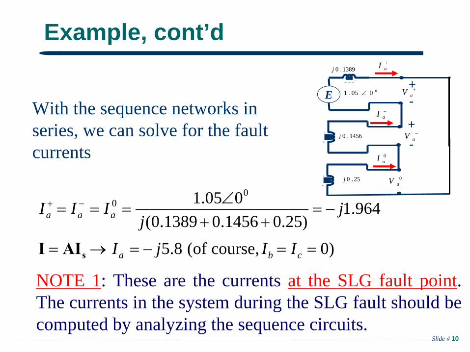
With the sequence networks in series, we can solve for the fault currents
)0course,of(8.5
964.1)25.01456.01389.0(
005.1 00
cba
aaa
IIjI
jj
III
sAII
NOTE 1: These are the currents at the SLG fault point. The currents in the system during the SLG fault should be computed by analyzing the sequence circuits.
aI
E
1389.0j
0005.1
aV+-
aI
aV
+-
0aV
0aI
25.0j
1456.0j

Slide # 11
Example, cont’d
From the sequence currents we can find the sequence voltages as follows:
178.0166.1,178.0166.1,0
,,005.1 00
jVjVV
ZIVZIVZIV
cba
ooaaaaaa
sAVV
NOTE 2: These are the voltages at the SLG fault point. The voltages at other locations in the system (during the SLG fault) should be computed by analyzing the sequence circuits.
Slide # 12
Line-to-Line (LL) Faults
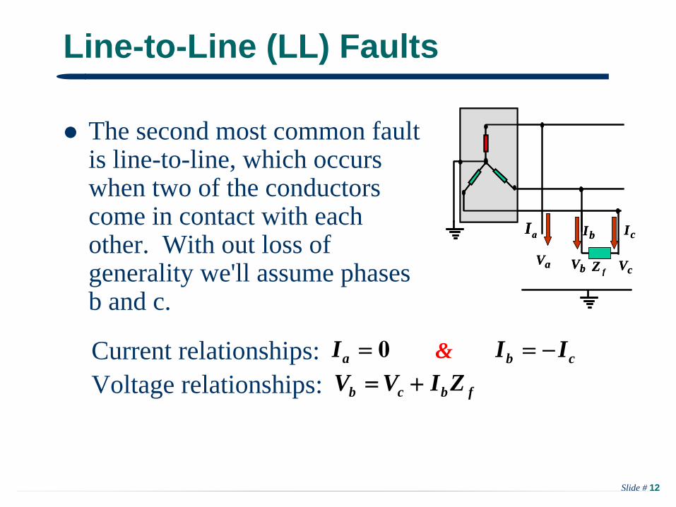
The second most common fault is line-to-line, which occurs when two of the conductors come in contact with each other. With out loss of generality we'll assume phases b and c.
bV
bI
cV
cI
aV
aI
fZbV
bI
cV
cI
aV
aI
fZ
0aI cb II
fbcb ZIVV &Current relationships:
Voltage relationships:
Slide # 13
LL Faults, cont'd
b
b
I
I
0
2
2
1
1
111
31
a
a
a
I
I
I 0
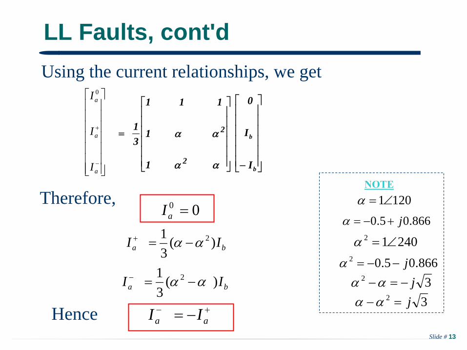
Using the current relationships, we get
00 aI
aa II
ba II )(31 2
ba II )(31 2
24012
1201NOTE
32 j866.05.02 j
866.05.0 j
32 j
Therefore,
Hence

Slide # 14
LL Faults, con'td
00 aI
00 aI0000 ZIV aa
Therefore, it is obvious that, during a LL Faults there is no zero sequence components in the sequence circuit that represents this fault.
Using the symmetrical components, then:
fbcb ZIVV
aaab VVVV 20
During LL fault, we have:
)( 20 aaaffb IIIZZI
cV
aI
bV
bI
cVaV
aIfZ
++
__
+
_
0Vao 0Vao oZoZ
aaac VVVV 20
Slide # 15
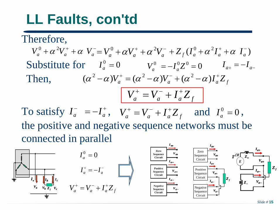
LL Faults, con'tdTherefore,
aaa VVV 20 aaa VVV 20 )( 20 aaaf IIIZ
aa II00 aI
faaa ZIVV )()()( 222
faaa ZIVV
Substitute for 0000 ZIV aa
Then,
ZeroSequenceCircuit
NegativeSequenceCircuit
PositiveSequenceCircuit
aoI
aI
aI
aV
aV
aoVZero
SequenceCircuit
ZeroSequenceCircuit
NegativeSequenceCircuit
NegativeSequenceCircuit
PositiveSequenceCircuit
PositiveSequenceCircuit
aoI
aI
aI
aV
aV
aoV
bV
bI
cV
cI
aV
aI
fZbV
bI
cV
cI
aV
aI
fZ
ZeroSequence
Circuit
NegativeSequence
Circuit
PositiveSequence
Circuit
aoI
aI
aI
aV
aV
aoV
fZ
ZeroSequence
Circuit
ZeroSequence
Circuit
NegativeSequence
Circuit
NegativeSequence
Circuit
PositiveSequence
Circuit
PositiveSequence
Circuit
aoI
aI
aI
aV
aV
aoV
fZ
00 aI
aa II
faaa ZIVV
aI
aI
aV
aV
E
Z
Z01
fZ
aI
aI
aV
aV
E
Z
Z01
fZ
To satisfy 00 aI aa II faaa ZIVV , and ,the positive and negative sequence networks must be connected in parallel

Slide # 16
LL Faults-Example
0005.1
1456.0j
aI
0aV
0aI
25.0j
1389.0j
E
fZE
fZaI
aV
aV
1456.0j0005.1 E
fZ
E
fZ1389.0j
aV
aI
aV
aI
In the previous example, assume a phase-b-to-phase-c fault occurs at the busbar of generator 2 (G2 )
39.6
39.6
0
90691.3
90691.3
0
0
0
2
2
1
1
111
31
c
b
a
I
I
I
Solving the network for the currents, we get0
0
90691.3)1456.01389.0(
005.1
jIa
Note: Zf = 0
Slide # 17
LL Faults-Example, cont'd
2
2
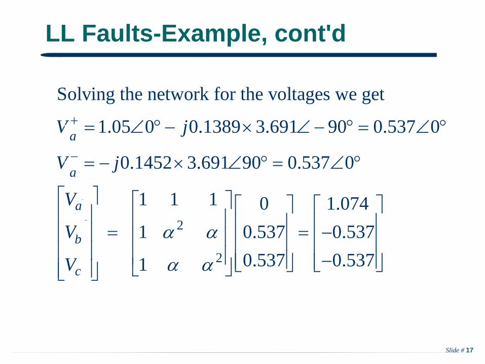
Solving the network for the voltages we get
1.05 0 0.1389 3.691 90 0.537 0
0.1452 3.691 90 0.537 0
1 1 1 0 1.0741 0.537 0.537
0.537 0.5371
f
f
faf
bf
c
V j
V j
V
V
V
a
a
Slide # 18
Double Line-to-Ground Faults
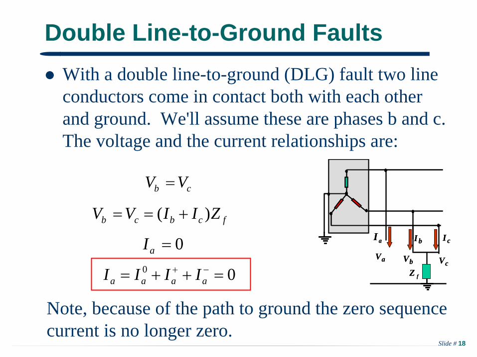
With a double line-to-ground (DLG) fault two line conductors come in contact both with each other and ground. We'll assume these are phases b and c. The voltage and the current relationships are:
bV
bI
cV
cI
aV
aI
fZbV
bI
cV
cI
aV
aI
fZ
cb VV
fcbcb ZIIVV )(
0aI
00 aaaa IIII
Note, because of the path to ground the zero sequence current is no longer zero.

Slide # 19
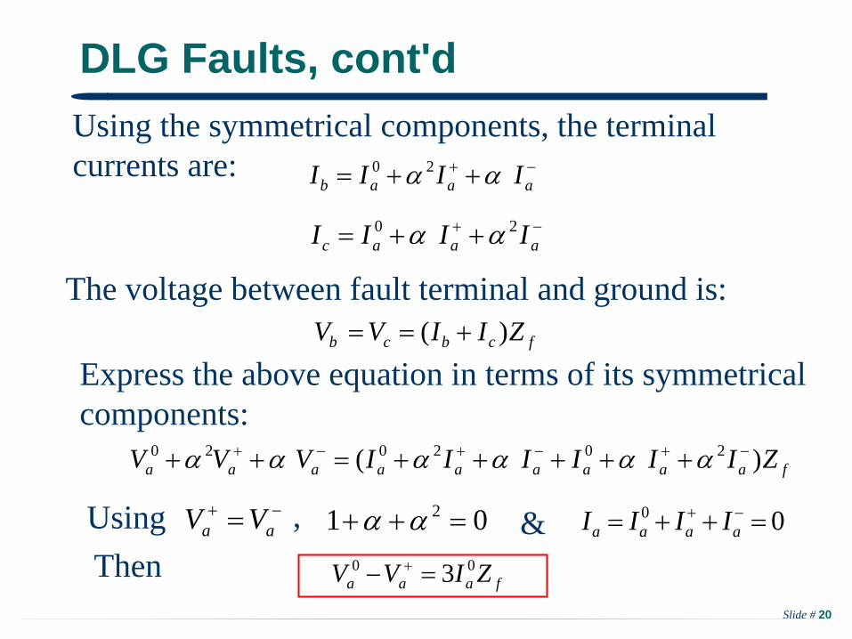
DLG Faults, cont'dUsing the symmetrical components, the terminal voltages are: bbbb VVVV 0
aaab VVVV 20
aaaaaa VVVVVV 2020 cb VV
aa VV
aa VV )()( 22
aaac VVVV 20
Slide # 20
DLG Faults, cont'd
faaaaaaaaa ZIIIIIIVVV )( 202020
Using the symmetrical components, the terminal currents are: aaab IIII 20
aaac IIII 20
fcbcb ZIIVV )( The voltage between fault terminal and ground is:
Express the above equation in terms of its symmetrical components:
aa VV 01 2 00 aaaa IIIIUsing &,
faaa ZIVV 00 3 Then
Slide # 21
DLG Faults, cont'd
aoI
ZeroSequence
Circuit
ZeroSequence
Circuit
NegativeSequence
Circuit
NegativeSequence
Circuit
PositiveSequence
Circuit
PositiveSequence
Circuit
aI
aI
aV
aV
aoV
bV
bI
cV
cI
aV
aI
fZbV
bI
cV
cI
aV
aI
fZ
ZeroSequence
Circuit
ZeroSequence
Circuit
NegativeSequence
Circuit
NegativeSequence
Circuit
PositiveSequence
Circuit
PositiveSequence
Circuit
aoI
aI
aI
aV
aV
aoV
fZ3
aoI
aI
aI
aV
aV
aoV
E
Z
Z
oZ
01
fZ3
aoI
aI
aI
aV
aV
aoV
E
Z
Z
oZ
01
fZ3
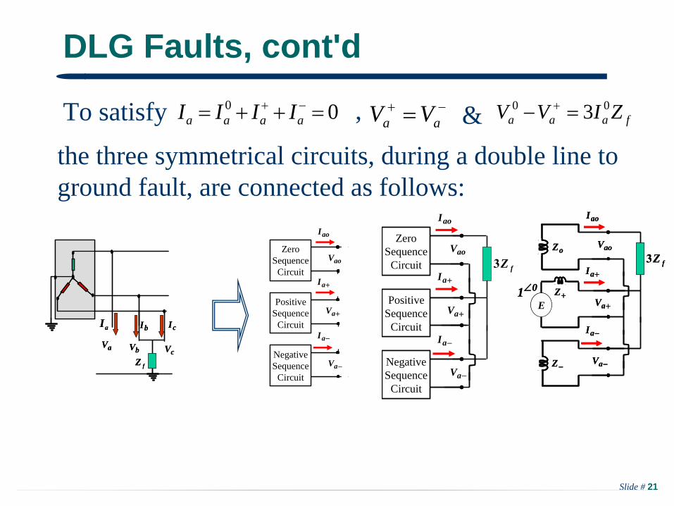
the three symmetrical circuits, during a double line to ground fault, are connected as follows:
To satisfy &, aa VV00 aaaa IIII faaa ZIVV 00 3
Slide # 22
DLG Faults-Example
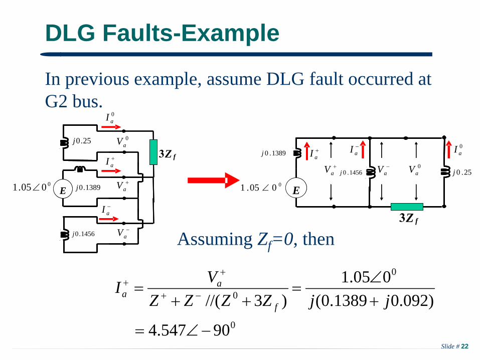
In previous example, assume DLG fault occurred at G2 bus.
Assuming Zf =0, then
0
0
0
90547.4
)092.01389.0(005.1
)3//(
jjZZZZVI
f
aa
1389.0j0005.1
25.0j
1456.0j
E
fZ3
EaI
0aI
0aV
aV
aV
aI
aI
E
fZ3
E0005.1
1389.0j
25.0j1456.0j
aV
aI
aV 0
aV
0aI
Slide # 23
DLG Faults, cont'd
aI
E
fZ3
E0005.1
1389.0j
25.0j1456.0j
aV
aI
aV 0
aV
0aI
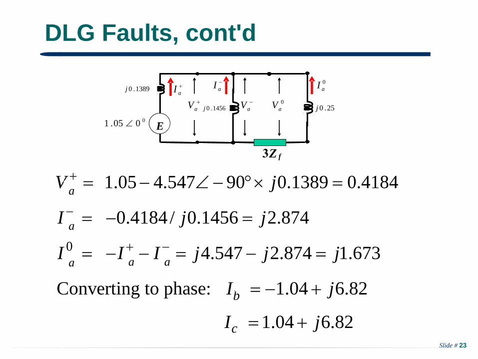
0
1.05 4.547 90 0.1389 0.4184
0.4184/ 0.1456 2.874
4.547 2.874 1.673
Converting to phase: 1.04 6.82
1.04 6.82
f
f
f f f
fbf
c
V j
I j j
I I I j j j
I j
I j
a
a
a
a a
Slide # 24
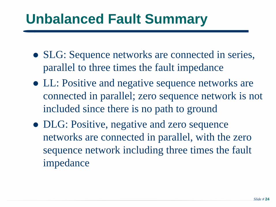
Unbalanced Fault Summary
SLG: Sequence networks are connected in series, parallel to three times the fault impedance
LL: Positive and negative sequence networks are connected in parallel; zero sequence network is not included since there is no path to ground
DLG: Positive, negative and zero sequence networks are connected in parallel, with the zero sequence network including three times the fault impedance
Slide # 25
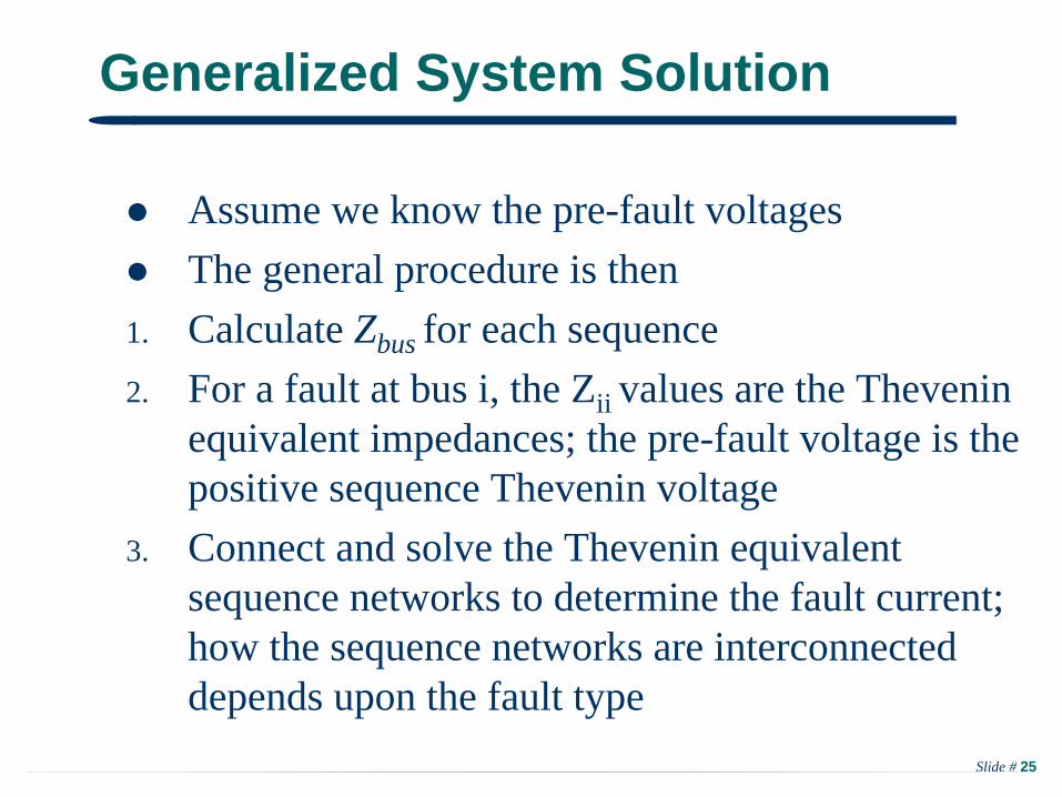
Generalized System Solution
Assume we know the pre-fault voltages
The general procedure is then
1. Calculate Zbus for each sequence2. For a fault at bus i, the Zii values are the Thevenin
equivalent impedances; the pre-fault voltage is the positive sequence Thevenin voltage
3. Connect and solve the Thevenin equivalent sequence networks to determine the fault current; how the sequence networks are interconnected depends upon the fault type

Slide # 26
Generalized System Solution, cont’d
4. Sequence voltages throughout the system are given by 0
0
0
0
prefaultfIZ
V V
This is solvedfor each sequence network!
5. Phase values are determined from the sequence values
Slide # 27
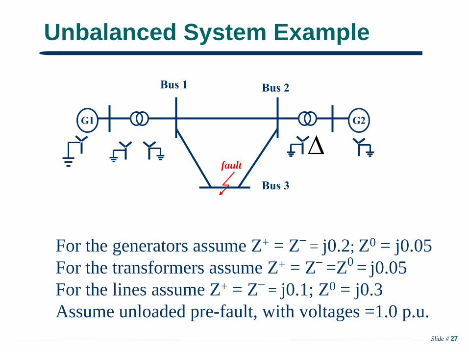
Unbalanced System Example
For the generators assume Z+ = Z
= j0.2; Z0 = j0.05For the transformers assume Z+ = Z
=Z0 = j0.05
For the lines assume Z+ = Z
= j0.1; Z0 = j0.3Assume unloaded pre-fault, with voltages =1.0 p.u.
G1
Bus 1
G2
fault
Bus 2
Bus 3

Slide # 28
Positive/Negative Sequence Network
24 10 10 0.1397 0.1103 0.12510 24 10 0.1103 0.1397 0.12510 10 20 0.1250 0.1250 0.175
bus busj
Y Z
Negative sequence is identical to positive sequence
j0.2 j0.05 j0.1
o00.1 o00.1
Bus 1
fault
Bus 2
Bus 3
j0.05 j0.2
j0.1j0.1
j
Slide # 29
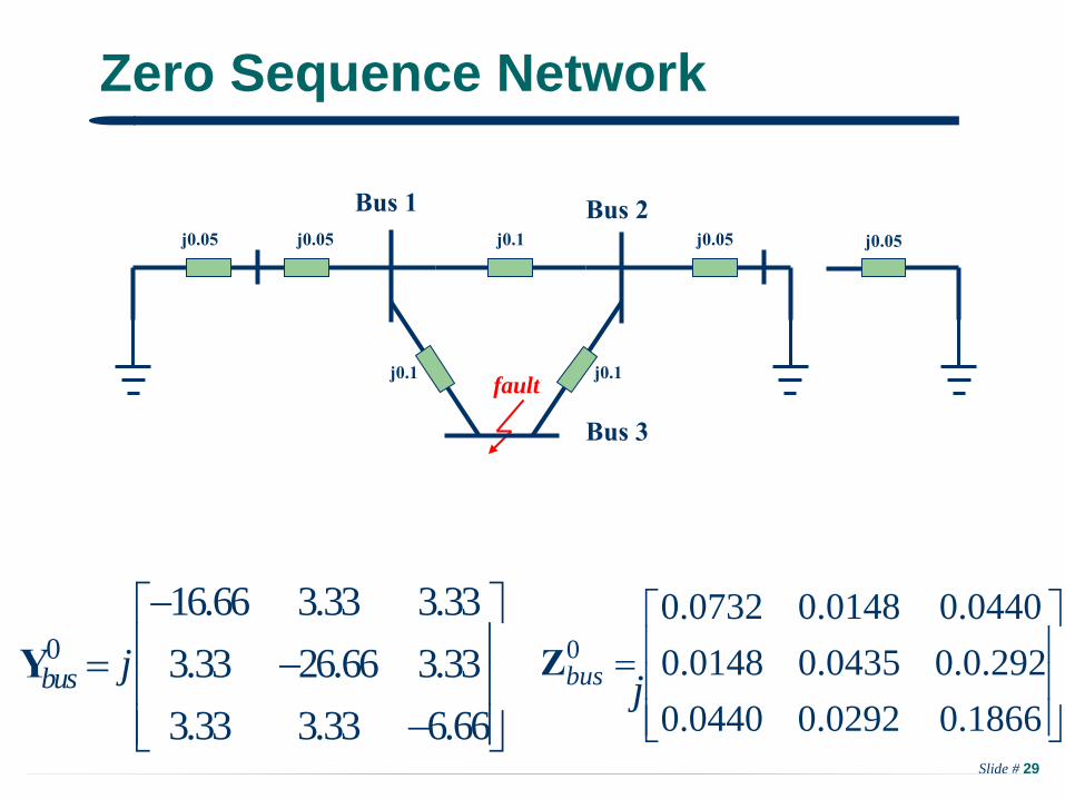
Zero Sequence Network
016.66 3.33 3.333.33 26.66 3.333.33 3.33 6.66
bus j
Y
j0.05 j0.05 j0.1
Bus 1
fault
Bus 2
Bus 3
j0.05 j0.05
j0.1j0.1
00.0732 0.0148 0.04400.0148 0.0435 0.0.2920.0440 0.0292 0.1866
bus
Zj
Slide # 30
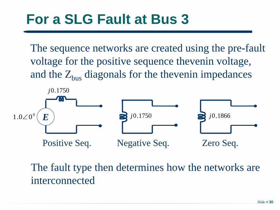
For a SLG Fault at Bus 3
The sequence networks are created using the pre-faultvoltage for the positive sequence thevenin voltage,and the Zbus diagonals for the thevenin impedances
Positive Seq. Negative Seq. Zero Seq.
The fault type then determines how the networks areinterconnected
E
1750.0j
000.1 1866.0j1750.0j
Slide # 31
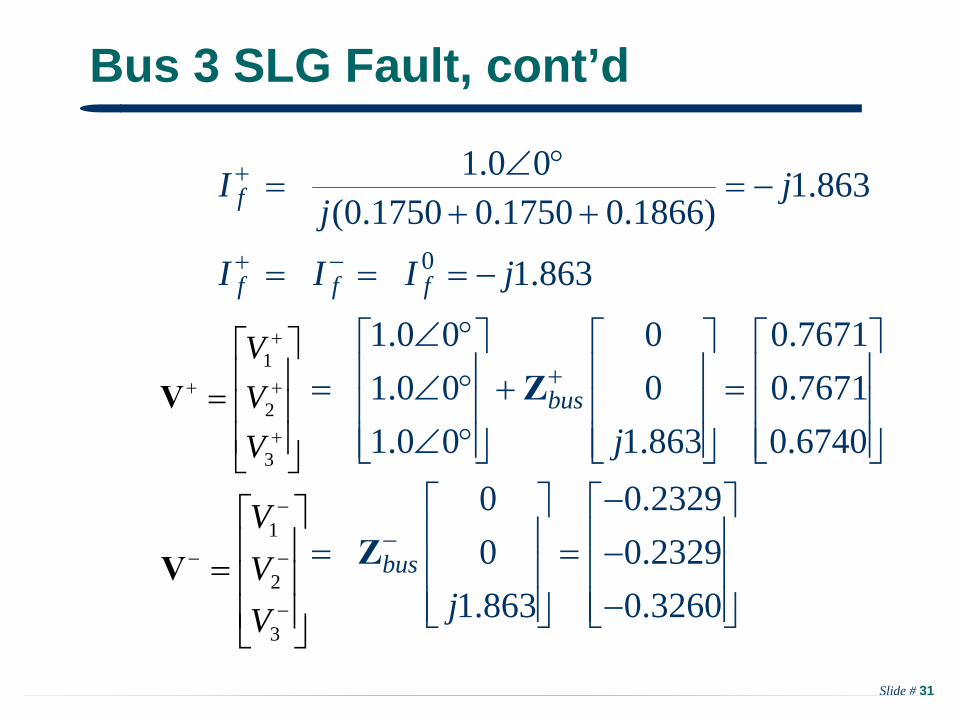
Bus 3 SLG Fault, cont’d
0
1.0 0 1.863(0.1750 0.1750 0.1866)
1.863
1.0 0 0 0.76711.0 0 0 0.76711.0 0 1.863 0.6740
0 0.23290 0.2329
1.863 0.3260
f
f f f
bus
bus
I jj
I I I j
j
j
V Z
V Z
3
2
1
VVV
V
3
2
1
VVV
V

Slide # 32
Bus 3 SLG Fault, cont’d
0 0
3
1
0 0.08200 0.0544
1.863 0.3479We can then calculate the phase voltages at any bus
0.3479 00.6740 0.522 0.8660.3260 0.522 0.8660.0820
0.7671
bus
j
jj
V Z
V A
V A0.4522
0.3491 0.8660.2329 0.3491 0.866
jj
c
b
a
VVV
3V
c
b
a
VVV
1V
0
3
02
01
0
VVV
V
Slide # 33
Faults on Lines
The previous analysis has assumed that the fault is at a bus. Most faults occur on transmission lines, not at the buses
For analysis these faults are treated by including a dummy bus at the fault location. How the impedance of the transmission line is then split depends upon the fault location
Slide # 34
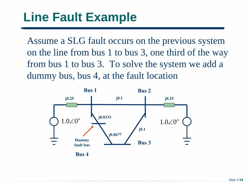
Line Fault Example
Assume a SLG fault occurs on the previous system on the line from bus 1 to bus 3, one third of the wayfrom bus 1 to bus 3. To solve the system we add adummy bus, bus 4, at the fault location
j0.25 j0.1
o00.1 o00.1
Bus 1 Bus 2
Bus 3
j0.25
j0.1
j0.0333
j0.0677Dummy fault bus
Bus 4

Slide # 35
Line Fault Example, cont’d
44 10 0 3010 24 10 00 10 25 1530 0 15 45
Adding the dummy bus only changes the newrow/column entries associated with the dummy bus
0.1397 0.1103 0.1250 0.13480.1103 0.1397 0.1250 0.11520.125
bus
bus
j
j
Y
Z0 0.1250 0.1750 0.1417
0.1348 0.1152 0.1417 0.1593
The Ybusnow has4 buses