uml2 as an adl hierarchichal hardware modeling … · architecture description languages 133 uml2...
TRANSCRIPT
Architecture Description Languages 133
UML2 AS AN ADL HIERARCHICHALHARDWARE MODELING
Arnaud [email protected]
Philippe [email protected]
Jean-Luc [email protected]
Laboratoire d'informatiquefondamentale de LilleUniversite des sciences et technologies de LilleFrance
Abstract Taking into account the hardware architecture specificities is a crucial step inthe development of an efficient application. This is particularly the case for em-bedded systems where constraints are strong (real-time) and resources limited(computing, power). This approach is called co-design, and it is found moreor less explicitly in ADLs. Much work have been done around co-design andADLs, but no standard notation and semantics have emerged. Concerning soft-ware engineering, UML has become a recognized standard language for mod-eling, proving the need of users for common syntax and vocabulary to specifytheir applications. We believe that it would useful to use the well achieved syn-tax and vocabulary of UML for both applications and hardware architectures,that is to say using UML as an ADL. Our approach consists in a clear special-ization of an UML subset via a the proposition of a generic profile that allowsthe definition of precise semantic and syntaxic rules. The generic profile canthen be extended to suit the need of the user. To illustrate our subject, we givea refinement example of the profile to get relevant informations for a simula-tion at the TLM level (Transaction Level Modeling). The modeling of the TexasInstrument OMAP2410 and OMAP2420 is provided as an example.

134 Architecture Description Languages
1. Hardware Modeling and UML
The usage of an ADL permits to represent static or dynamic characteris-tics of a system. This system is either a software or a hardware system. Forembedded systems, both system are defi ned: you need to co-design your ap-plication and your hardware platform in the same time with respect to specifi cconstraints.
Concerning software engineering, UML (Unifi ed Modeling Language) [Ob-ject Management Group, Inc., 2003] has become a standard language for mod-eling. It does not present a particular methodology and it can be used to modeldifferent point of view of the same model. UML 2 introduces the compo-nent notion and structure diagrams that facilitate architecture modeling. Withdeployment diagrams, UML 2 also considers hardware descriptions and map-ping. Unfortunately, the model for applications differs from the model forhardware. The same comment applies for the mapping of an application on aparticular hardware, for example a System on Chip: we want to benefi t fromthe component notion, the hierarchical constructs of the structural and behav-ioral diagrams for the hardware design as well as for the software design.
We defi ne our hardware description metamodel based on the UML 2.0component notion. The structural specifi cation is suffi cient to generate Sys-temC [Open SystemC Initiative, 2002] code to produce a TLM (TransactionLevel Modeling) simulation once the mapping of an application on this hard-ware model is achieved.
1.1 Related Work
Several proposals, emerged from the OMG world or not, introduce hardwaremodeling techniques and/or concepts. Only a few ones are "sold" as ADLs.
AADL [Feiler et al., 2003] (Avionics Architecture Description Language)is the only proposal which clearly advocates the use of UML as an ADL. Thislanguage is based on MetaH. It is used to describe the structure of an embeddedsystem as a gathering of software and hardware components. It can describeboth functional (data inputs and outputs) and non functional (such as timing)aspects of components. A UML profi le for AADL (based on UML 2) is understandardization, and will be soon submitted to the OMG. Concerning the hard-ware modeling part of this proposal, four concepts are introduced: memory,processor, bus and device. We will see later in this paper that our proposal isnot semantically far from this one. However, the goal of hardware modeling(called platform) in AADL is not the same as ours. The platform specifi ca-tion is more or less used to apply schedulability and fault tolerance analysisverifi cation tools (that is to say to verify that a software associated to one plat-form meets the requirements that the system must satisfy), whereas the toolswe plan to use are rather optimization tools (for mapping of computing, data,

Architecture Description Languages 135
and communications). Moreover, we can't clearly see in the specifi cation ofthe language how the hardware concepts can be composed and/or assembled.
The UML SPT Profile [Object Management Group, Inc., 2002] (Schedul-ing, Performance, and Time analysis) is an UML 1.x OMG standard profilefor embedded systems modeling. It introduces various hardware (or more gen-erally platform) modeling concepts and an interesting resource classifi cationaccording to three criteria: purpose (processor, communication and device),activeness (a resource is active when it is able to generate stimuli, and passivewhen it is only able to react when prompted by stimuli), and protection (a re-source is protected when the access to services it offers is restricted accordingto some control access policy). However, the profi le gives no clear orientationand methodology on the way it can be used. Moreover, the underlying exe-cution model (a resource is acquired and then released) is too restrictive andunfortunately does not suit our needs.
HaSoC [Green and Edwards, 2002a, Green and Edwards, 2002b] (Hard-ware and Software Objects on Chip) is a platform-based design methodologyusing UML to represent high-level structure and behaviour of the hardware ar-chitecture model of an application platform. The hardware architecture modelof HASoC distinguishes general-purpose hardware (processors, memory), pro-grammable logic (FPGAs), fi xed-function (custom) hardware, and intercon-nection elements. This model enables to generate SystemC code for simulationand particularly for hardware synthesis. For our purpose, distinction betweenprogrammable and non programmable units is not necessary x, as hardwaresynthesis is not one of our goal. Moreover, this model doesn't seem to exploithierarchical capabilities offered by UML 2.
The SLOOP [Zhu et al., 2002] (System Level design with Object-OrientedProcess) design process integrates a methodology based on UML for both SoCmodeling and performance evaluation at system level. The hardware modelproposed is similar to those previously presented: it proposes hardware ele-ments such as processors, memories, buses and hardware devices. However,the hardware architectures are modeled via deployment diagrams, with variousstereotypes applied to "Nodes". This choice has the benefi t of being simple andrelatively natural for people coming from the UML world. Indeed, deploymentdiagrams are used to coarsely describe execution platforms for applications.But we believe that deployment diagrams are too restrictive to model archi-tectures (no hierarchy, no encapsulation via ports and interfaces, no behaviordescription...), and that the same model must be used for both hardware andsoftware.
136 Architecture Description Languages
1.2 Proposal
Our approach consists in a clear specialization of an UML subset for whichwe can defi ne precise syntactic and semantic rules. This prevents from all kindof ambiguities in the model2.
The abstract syntax of our model is described by a MOF metamodel defi nedas an extension of the UML 2 metamodel. The metamodeling brings a set oftools which will enable us to specify our application and hardware architec-ture models using UML tools, to reuse functional and physical IPs, to ensurerefi nements between abstraction levels via mapping rules, to ensure interoper-ability between the different abstraction levels used in a same codesign, andto ensure the opening to other tools, like verifi cation tools, thought the useof standards. The concrete syntax is defi ned by a profi le for UML 2. Thisprofi le is, for the moment, only based on UML 2 class diagrams and internalstructure diagrams3. In this paper, we focus on the description of the pro-fi le(there is almost a "one to one" equivalence between concepts introducedin the metamodel and stereotypes introduced in the profi le). The generic rulesand concepts are described in a generic part of the profi le. This generic ele-ments are then refi ned via an extension of the profi le to fi t to the needs of theuser (documentation, simulation at various abstraction levels, optimization...).
The fi rst part of the paper summaries the so-called "Y model approach" [Du-moulin et al., 2003], and describes the generic part of the profi le, focusing onthe set of "basic blocks" that defi ne the syntax and semantics of our hardwarearchitecture model. Therefore, we propose a classifi cation, at the same timeboth functional and structural, in order to identify each kind of components4
of our model. Then, we specify the construction rules which govern compo-nents assembling and composition.
The second part of this document shows how an extension of the profi lecan be used to refi ne the "basic blocks", in order to produce models suited toa particular use. For that, we give an extension of the used profi le to gatherrelevant informations of a simulation at a TLM level in an environment suchas SystemC. As a conclusion, we illustrate our subject with a case study: theTIOMAP2410 and OMAP2420 [Texas Instruments, 2004].
2. Y Model Approach
Our proposal is partially based upon the "Y-chart" concepts [Gajski andKuhn, 1983]. A clear distincition is made between application and hardware,which are related via an explicit mapping.
The application and hardware architecture are described by different meta-models. Some concepts handle within these two metamodels are similar inorder to unify and so simplify their understanding and use.

Architecture Description Languages 137
- Applca Ion and araitloc uroaeeadalcnconoap-ie
PIM
PSM
TDfaMlxtoi Fnaxaa Nttmn
Figure 1. Y Model Approach
The proposed methodology is to separately design the two models for theapplication and the hardware architecture (maybe by two different people).At this point, it becomes possible to map the application model on the hard-ware architecture model. For this purpose we introduce a third metamodel, theso-called association metamodel, to express the associations between the func-tional components of the application model and the hardware components ofthe hardware model. This third metamodel imports the fi rst two metamodels.
3. Hierarchical Hardware Architecture Model
We present here the different hardware components that we introduce in ourmodel, and we give the rules on the way to compose and assemble them witheach other.
The hardware components represent abstractions of physical hardware ar-chitecture elements. A hardware component owns an interface materialized byits ports, and a structure defi ned by an assembly of components via an internalstructure diagram.
3.1 Resource Classification
We propose to classify the resources according to two criteria: a functionalcriterion, and a structural criterion (Fig. 2). Each resource is characterized bya composition of these two criteria. In UML, it comes to apply two stereotypesto each component.
138 Architecture Description Languages
szo13owmu
CO
0..1 0
rTTDMetam^t^cturaFsature
.1
HwComponent
ElementaryHvuflComponent
AA A A
CompoundHwComponent
RepetitionHwComponent
ActiveComponent
PasmveComponent
InierconnectComponent
T l
3
I
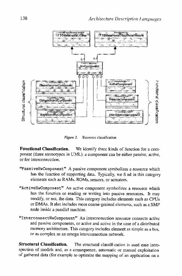
Figure 2. Resource classification
Functional Classification. We identify three kinds of function for a com-ponent (three stereotypes in UML): a component can be either passive, active,or for interconnection.
"PassiveHwComponent" A passive component symbolizes a resource whichhas the function of supporting data. Typically, we fi nd in this categoryelements such as RAMs, ROMs, sensors, or actuators.
"ActiveHwComponent" An active component symbolizes a resource whichhas the function or reading or writing into passive resources. It maymodify, or not, the data. This category includes elements such as CPUsor DMAs. It also includes more coarse-grained elements, such as a SMPnode inside a parallel machine.
"InterconnectHwComponent" An interconnection resource connects activeand passive components, or active and active in the case of a distributedmemory architecture. This category includes element as simple as a bus,or as complex as an omega interconnection network.
Structural Classification. The structural classifi cation is used ease intro-spection of models and, as a consequence, automatic or manual exploitationof gathered data (for example to optimize the mapping of an application on a
Architecture Description Languages 139
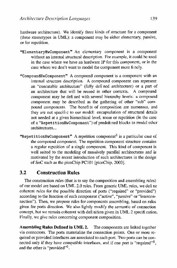
hardware architecture). We identify three kinds of structure for a component(three stereotypes in UML): a component may be either elementary, passive,or for repetition.
"ElementaryHwComponent" An elementary component is a componentwithout an internal structural description. For example, it could be usedin the case where we have an hardware IP for this component, or in thecase where we don't want to model the component more fi nely.
"CompoundHwComponent" A compound component is a component with aninternal structure description. A compound component can representan "executable architecture" (fully defined architecture) or a part ofan architecture that will be reused in other contexts. A compoundcomponent may be defi ned with several hierarchy levels: a compoundcomponent may be described as the gathering of other "sub" com-pound components. The benefi ts of composition are numerous, andthey are not specifi c to our model: encapsulation of structural detailsnot needed at a given hierarchical level, reuse or repetition (in the caseof a "RepetitionHwComponent") of predefi ned blocks to model otherarchitectures...
"RepetitionHwComponent" A repetition component5 is a particular case ofthe compound component. The repetition component structure containsa regular repetition of a single component. This kind of component iswell suited to the modeling of massively parallel architectures and ismotivated by the recent introduction of such architectures in the designof SoC such as the picoChip PC101 [picoChip, 2003].
3.2 Construction Rules
The construction rules (that is to say the composition and assembling rules)of our model are based on UML 2.0 rules. From generic UML rules, we defi necoherent rules for the possible direction of ports ("required" or "provided")according to the function of each component ("active", "passive" or "intercon-nection"). Then, we propose rules for components assembling, based on rulesgiven for ports direction. We also lightly modify the semantic of connectionconcept, but we remain coherent with defi nition given in UML 2 specifi cation.Finally, we give rules concerning component composition.
Assembling Rules Defined in UML 2. The components are linked togethervia connectors. The ports materialize the connection points. One or more re-quired or provided interfaces are associated to each port. Two ports can be con-nected only if they have compatible interfaces, and if one port is "required"6,and the other is "provided"0.

140 Architecture Description Languages
The methods associated to each interface represent services. A compo-nent with a required port is able to emit services requests to its environment,whereas a component with a provided port provides a set of services to itsenvironment.
Ports "direction". We use assembling rules defi ned in UML to restrictpossible directions of ports (required or provided) associated to each kind ofcomponents of our architecture model.
A passive component only owns provided ports, as it can only propose ser-vices for data support (read/write) to active components. An active componenttypically owns required ports, as it can emit read or write services requests topassive components. It can also own provided ports to receive requests emittedby other active components, for example in the case of a distributed memoryarchitecture. An interconnection component owns required and provided, as ithas the function of linking active and passive components, or active and(Fig. 5)active components.
Assembling Rules. Respecting rules previously mentioned, two passivecomponents can not be connected together (on both sides, there are only pro-vided ports). We add the constraint that all connections between active andpassive components or between active and active components must be done viaan interconnection component. This constraint enables to ease and systematizethe parsing of models. Moreover, a clear identifi cation of the interconnectionresources enables to associate properties to these resources (such as bandwidth,or latency).
Connections Semantics. Services associated to ports are implicit accordingto the function of the component and the defi nition we gave of these functions(the active components require read/write services to passive components viainterconnection components). As a consequence, an incomplete model in thestandard UML formalism (that is to say with no interfaces associated to ports)can be interpreted without ambiguities in the context of our profi le. The userof the profi le is free to add the interface suited to the case he is modeling.
Connections between ports are interpreted as potential data paths offered byarchitecture, more than paths for services exchanges. This semantics is closeto the semantics of connections between modules in SystemC.
In our case, the association of interfaces to ports in a hardware architectureis a way to refi ne its specifi cation according to application mapped on thisarchitecture.
Composition Rules. A passive compound component may only containother passive components. A active compound component can only contain

Architecture Description Languages 141
other interconnection components. An active component can contain all kindsof component. The top level component in the hierarchy is necessarily a activecompound (or repetition) component. By this way, the parsing of an architec-ture consists in a traversal of active compound or repetition components.
4. A Profile Refinement for TLM Level SimulationIn this section, we show a refi nement of the generic profi le designed to get
relevant informations from a simulation at a TLM level, such as execution time,load of interconnection elements, load balancing of active elements... The pro-fi le refi nement consists in extending stereotypes defi ned in the generic partby adding them properties. First of all, we describe data types associated toproperties of various modeling elements. Then, we show successively a refi ne-ment for active elements, for passive elements, and fi nally for interconnectionelements.
4.1 Data Types
Data types described here are used to type properties added to various re-fi ned model elements:
TimeExpression is an expression representing a duration ("13ns")
FrequencyExpression is an expression representing a clock frequency("1.2MHz")
CapacityExpression is an expression representing a capacity ("16Mo")
BandWidthExpression is an expression representing a bandwidth("3.5Go/s")
4.2 Active Component Refinement
To refi ne the concept of active component, we introduce two kinds of com-ponents: "CPU" and "DMA" (Fig. 3). These components extend (in a UML pointview, but particularly in a semantic point of view) the defi nition of the activecomponent.
'CPU" Component. A CPU represents a resource able to read and writein passive resources, with or without data modifi cations. It also symbolizes aresource able to execute functions defi ned in the application model. It is po-tentially able to execute all functions, except if the list of functions is explicitlyrestricted7. CPU is a generic term gathering CPUs (strict meaning), DSPs, oreven FPGAs (i.e. all kind of programmable or not programmable resource ableto realize a computation on data). A CPU is characterized by four attributes:

142 Architecture Description Languages
ActtveComponent
CPU
frequency: Frequence/ExpressionwordSize: IntegerdataCache; CapacityExpressioninstructionCache. CapacrtyExpression
< <stereotype»DMA
channels'. IntegercycleStealing: Boolean
Figure 3. Active component refinement
frequency: Frequency-Expression. This property represents the clock fre-quency of the CPU. For example, it can be used to determin the exe-cution duration of a function, in the case where the number of cyclesnecessary to execute this function on this CPU is known.
wordSize: Integer. This property represents the size of the words handledby the CPU. The size expression unit is the bit.
dataCache: CapacityExpression. This property represents the size of thedata cache of the CPU.
instructionCache: CapacityExpression. This property represents thesize of the instruction cache of the CPU.
'DMA"Component. A DMA is characterized by its number of channels andby the policy it uses: whether it is based on cycle-stealing or not.
4.3 Passive Component Refinement
To refi ne the concept of passive component, we introduce three kinds ofcomponent: "Memory", "Sensor" and "Actuator" (Fig. 4). These compo-nents extend (in a UML point view, but particularly in a semantic point ofview) the defi nition of the passive component.
'Memory" Component. A memory has the function of supporting data. Itis characterized by six attributes:
capacity: CapacityExpression. This property represents the size of thememory.

Architecture Description Languages 143
_ _ _.
Memory
saga-ell? *
Sensor Actuator
Figure 4. Passive component refinement
la tency: TimeExpression. This property represents the latency related toa memory access. The value is expressed in time, and not in cycles, inorder to make easier the reuse of memory component for several archi-tecture modelings, or in the case of heterogeneous architectures (severalkinds of CPU accessing the same memory component).
readBandWidth: BandWidthExpression. This property represents the readbandwidth of the memory.
writeBandWidth: BandWidthExpression. This property represents thewrite bandwidth of the memory.
wordSize: CapacityExpression. This property represents the size of amemory word.
burs t : Integer . This property represents the number of memory word col-lected when an access in burst mode occurs.
'Sensor"Component. A sensor represents a resource able to periodicallycatch data from its environment, and put it at hardware architecture disposal.Sensors are classifi ed in the category of passive elements, in the way that theycan be considered as read only memories. A active element can periodicallyget (read) data to compute or move from it. A sensor is characterized by twoattributes:
la tency: TimeExpression. This property represents the latency related toa read access.
readBandWidth: BandWidthExpression. This property represents the readbandwidth of the sensor.

InterconnectComponent
144 Architecture Description Languages
Actuator"Component. An actuator is the opposite of a sensor, that isto say a resource that provides data from the hardware architecture to its en-vironment. Actuators are classifi ed in the category of passive elements, in theway that they can be considered as write only memories. An active componentcan periodically give (write) data to it. An actuator is characterized by twoattributes:
la tency: TimeExpression. This property represents the latency related toa write access.
writeBandWidth: BandWidthExpression. This property represents thewrite bandwidth of the actuator.
4.4 Interconnection Component Refinement
To refine the concept of intercon-nection component, we introduce onekind of component: "Interconnect"(Fig. 5). This component extends (in aUML point view, but particularly in a se-mantic point of view) the defi nition ofthe interconnection component.
i n t e r connec t " Component. Theinterconnect is not more precise seman-tically than the interconnection compo-nent defi ned in the generic part of theprofi le. It's just an interconnection en-riched with properties used for a simula-
„ i t T , . , * • J Figure 5. Interconnection component re-tion at a TLM level. It is charactenzed fin^ment
by two attributes:
la tency: TimeExpression. This property represents the latency related toan access to the interconnection component.
bandwidth: BandWidthExpression. This property represents the band-width of the interconnect.
5. Modeling examples: The TI OMAP2410 andOMAP2420
We present in this section two modeling examples. Specifi cations are delib-erately not complete, and are just introduced for an illustration purpose. Weillustrate the use of various modeling elements (refi ned or not) of our model,
«stereotype»Interconnect
latency ;TimeExpressionbandwidth: BandWidthExpression
Architecture Description Languages 145
« ActiveCompanent, GompoundComponent»
OMAP2410
p
a
Jntercorcn #ct:fri hw eoi
rt^
- Q
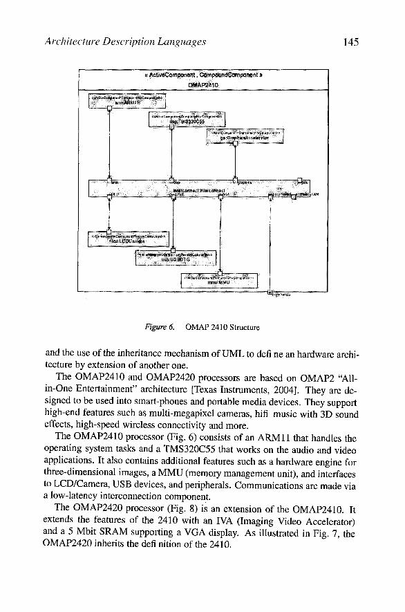
OMAP 2410 Structure
and the use of the inheritance mechanism of UML to defi ne an hardware archi-tecture by extension of another one.
The OMAP2410 and OMAP2420 processors are based on 0MAP2 "All-in-One Entertainment" architecture [Texas Instruments, 2004]. They are de-signed to be used into smart-phones and portable media devices. They supporthigh-end features such as multi-megapixel cameras, hifi music with 3D soundeffects, high-speed wireless connectivity and more.
The OMAP2410 processor (Fig. 6) consists of an ARM 11 that handles theoperating system tasks and a TMS320C55 that works on the audio and videoapplications. It also contains additional features such as a hardware engine forthree-dimensional images, a MMU (memory management unit), and interfacesto LCD/Camera, USB devices, and peripherals. Communications are made viaa low-latency interconnection component.
The OMAP2420 processor (Fig. 8) is an extension of the OMAP2410. Itextends the features of the 2410 with an IVA (Imaging Video Accelerator)and a 5 Mbit SRAM supporting a VGA display. As illustrated in Fig. 7, theOMAP2420 inherits the defi nition of the 2410.

146 Architecture Description Languages
««ActlveComponent,CompoundHwComponent»i»
OMAP 2410
.-.peripherals
<<ActlveComponent,CompoundHwComponent>>
OMAP2420
iia
y
Figure 7. Inheritance link between OMAP2410 and OMAP 2420 Figure 8. OMAP 2420 Structure
6. Conclusion
We have shown how we use UML 2 as an ADL, focusing on the hardwaremodel of our approach. The model we have presented enables a description ofhardware architectures at a high abstraction level. This model is implementedin a UML profi le. This profi le introduces generic concepts, with clear semanticand syntaxic basis, that can be refi ned for particular use. We gave an exampleof profi le refi nement to get relevant informations from a simulation at a TLMlevel, and we illustrated our subject with the modeling of the TI OMAP2410and OMAP2420.
This is only the fi rst step of our approach. We are currently working onmechanisms to express repetition of architectural elements. It enables for ex-ample to easily model regular hardware architectures such as hypercubes, orcomplex interconnection networks such as Omega networks. The repetitionsare expressed in the context of the "RepetitionHwComponent", with mecha-nisms similar to ones used in the application model to express data parallelismvia dependency expressions.
Moreover, we plan to soon introduce behavioral descriptions of hardwarecomponents. Typically, such informations would be taken into account in oursimulation environment. For example, it would be useful the describe the be-havior of a shared interconnect element (priority policy) to get informationsabout latency.

Architecture Description Languages 147
Notes
1. As we'll see later, we just tell which functions can be executed by a processing unit
2. This restriction does not mean that the usage of the other UML elements are forbidden. It onlymeans that all the elements added by a user in a model will not be taken into account by tools which exploitthe profi le.
3. We are investigating the introduction of activity diagrams, and possibly state diagrams, to modelhardware architecture behavior
4. In this document, the term 'Component" refers to UML 2 'StructuredClass".
5. This kind of component is part of a work in progress and will not be detailed in this paper.
6. A 'required port" refers to a port with a required interface , and a 'provided port" refers to a portwith a provided interface.
7. The way to restrict a list of executable functions is not described here. This problem is rather relatedto the association model.
References
[Dumoulin et al., 2003] Dumoulin, Cedric, Boulet, Pierre, Dekeyser, Jean-Luc, and Marquet,Philippe (2003). UML 2.0 structure diagram for intensive signal processing applicationspecification. Research Report RR-4766, INRIA.
[Feiler et al., 2003] Feiler, Peter H., Lewis, Bruce, and Vestal, Steve (2003). The SAE avionicsarchitecture description language (AADL) standard : A basis for model-based architecture-driven embedded systems engineering. In RTAS 2003 Workshop on Model-Driven Embed-ded Systems.
[Gajski and Kuhn, 1983] Gajski, D. D. and Kuhn, R. (1983). Guest editor introduction: NewVLSI-tools. IEEE Computer, 16(12):11-14.
[Green and Edwards, 2002a] Green, Peter and Edwards, Martyn (2002a). The modeling ofembedded systems using hasoc. In Design, Automation and Test in Europe Conference andExhibition (DATE '02), Paris, France.
[Green and Edwards, 2002b] Green, Peter and Edwards, Martyn (2002b). Platform modelingwith UML and systemc. In Forum on specification and Design Languages (FDL'02).
[Object Management Group, Inc., 2002] Object Management Group, Inc., editor (2002).(UML) Profile for Schedulability, Performance, and Time Specification, http: //www. omg.org/cgi-bin/doc?ptc/2002-03-02/.
[Object Management Group, Inc., 2003] Object Management Group, Inc., editor (2003).(UML 2.0): Superstructure Draft Adopted Specification, http: //www. omg. org/cgi -bin/doc?ptc/03-07-06/.
[Open SystemC Initiative, 2002] Open SystemC Initiative (2002). SystemC. http://www.systemc.org/.
[picoChip, 2003] picoChip (2003). PC101 and PC 102 datasheets, http://www.picochip.com/technology/picoarray.
[Texas Instruments, 2004] Texas Instruments (2004). OMAP 2 architecture,http://focus.ti.com/docs/general/splashdsp.jhtml?&path=templatedata/cm/°/0splashdsp/data/omap2.
[Zhu et al., 2002] Zhu, Qiang, Matsuda, Akio, Kuwamura, Shinya, Nakata, Tsuneo, and Shoji,Minoru (2002). An obect-oriented design process for system-on-chip using UML. In Pro-ceedings of the 15th international symposium on System Synthesis, pages 249-259, Kyoto,Japan.

SESSION 3: DOMAIN SPECIFICARCHITECTURE DESCRIPTIONLANGUAGES