regular hardware architecture modeling with uml2 · regular hardware architecture modeling with...
TRANSCRIPT
Regular Hardware Architecture Modeling with UML 2
Arnaud CUCCURU, Pierre BOULET, Jean-Luc DEKEYSERLaboratoire d’Informatique Fondamentale de Lille
University of Lille, France{Cuccuru,Boulet,Dekeyser}@lifl.fr
Abstract
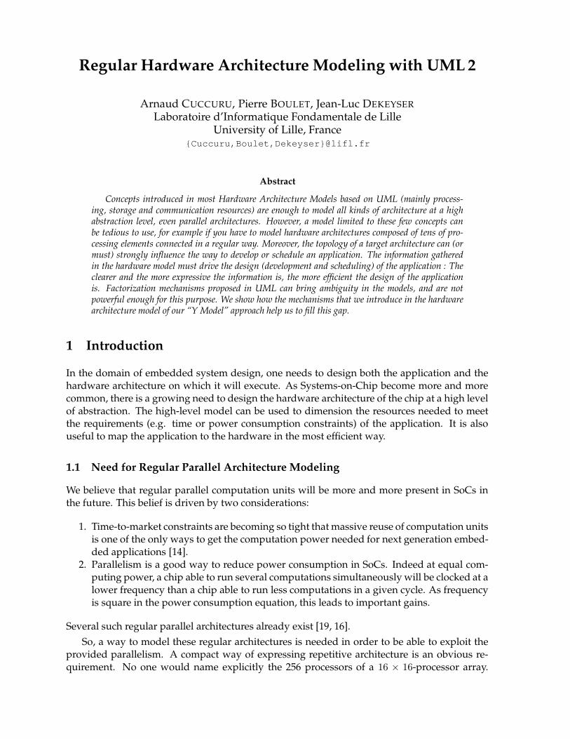
Concepts introduced in most Hardware Architecture Models based on UML (mainly process-ing, storage and communication resources) are enough to model all kinds of architecture at a highabstraction level, even parallel architectures. However, a model limited to these few concepts canbe tedious to use, for example if you have to model hardware architectures composed of tens of pro-cessing elements connected in a regular way. Moreover, the topology of a target architecture can (ormust) strongly influence the way to develop or schedule an application. The information gatheredin the hardware model must drive the design (development and scheduling) of the application : Theclearer and the more expressive the information is, the more efficient the design of the applicationis. Factorization mechanisms proposed in UML can bring ambiguity in the models, and are notpowerful enough for this purpose. We show how the mechanisms that we introduce in the hardwarearchitecture model of our “Y Model” approach help us to fill this gap.
1 Introduction
In the domain of embedded system design, one needs to design both the application and thehardware architecture on which it will execute. As Systems-on-Chip become more and morecommon, there is a growing need to design the hardware architecture of the chip at a high levelof abstraction. The high-level model can be used to dimension the resources needed to meetthe requirements (e.g. time or power consumption constraints) of the application. It is alsouseful to map the application to the hardware in the most efficient way.
1.1 Need for Regular Parallel Architecture Modeling
We believe that regular parallel computation units will be more and more present in SoCs inthe future. This belief is driven by two considerations:
1. Time-to-market constraints are becoming so tight that massive reuse of computation unitsis one of the only ways to get the computation power needed for next generation embed-ded applications [14].
2. Parallelism is a good way to reduce power consumption in SoCs. Indeed at equal com-puting power, a chip able to run several computations simultaneously will be clocked at alower frequency than a chip able to run less computations in a given cycle. As frequencyis square in the power consumption equation, this leads to important gains.
Several such regular parallel architectures already exist [19, 16].So, a way to model these regular architectures is needed in order to be able to exploit the
provided parallelism. A compact way of expressing repetitive architecture is an obvious re-quirement. No one would name explicitly the 256 processors of a 16 × 16-processor array.
Another good reason for wanting a factorized notation is that such a notation would be morecomprehensible for a compiler. As the regularity of the architecture is expressed, it can be ex-ploited to regularly map some repetitive computations (as usually appear in signal processingapplications) to the available processing units, thus decreasing the optimization time whileproducing some more efficient and compact code.
1.2 Hardware Modeling and UML
During the last four years, several proposals, emerged from the OMG world or not, have in-troduced hardware modeling techniques and/or concepts as extensions of UML [18] (UnifiedModeling Language).
AADL [7] (Avionics Architecture Description Language) is used to describe the structure of anembedded system as a gathering of software and hardware components. It can describeboth functional (data inputs and outputs) and non functional (such as timing) aspects ofcomponents. A UML profile for AADL (based on UML 2) is under standardization, andwill be soon submitted to the OMG. The hardware model part of this proposal introducesfour concepts : memory, processor, bus and device.
UML SPT Profile [17] (Scheduling, Performance, and Time analysis) is an UML 1.x OMG stan-dard profile for embedded system modeling. It introduces various hardware (or moregenerally platform) modeling concepts and an interesting resource classification accord-ing to three criteria: purpose (processor, communication and device), activeness (a resourceis active when it is able to generate stimuli, and passive when it is only able to react whenprompted by stimuli), and protection (a resource is protected when the access to servicesit offers is restricted according to some control access policy).
HaSoC [9, 10] (Hardware and Software Objects on Chip) is a platform-based design methodol-ogy using UML to represent the high-level structure and the behavior of the hardware ar-chitecture model of an application platform. The hardware architecture model of HaSoCdistinguishes general-purpose hardware (processors, memory), programmable logic (FP-GAs), fixed-function (custom) hardware, and interconnection elements. This model en-ables to generate SystemC code for simulation and particularly for hardware synthesis.
SLOOP [21] (System Level design with Object-Oriented Process) is a design process that inte-grates a methodology based on UML for both SoC modeling and performance evaluationat system level. The hardware model proposed is similar to those previously presented: itproposes hardware elements such as processors, memories, buses and hardware devices.
ACCORD/UML methodology [15] is basically an extension of UML for distributed real-timeembedded systems modeling, taking into account only the software part of a system. Inthe ACOTRIS project [1], ACCORD UML has been extended with hardware modelingfunctionalities. The hardware model is in fact the SynDEx [20] hardware model : Proces-sors are connected via Communication Media.
None of the above models proposes some specific way to express regular parallel architec-tures in a factorized way. UML itself proposes a few factorization mechanisms, though.
1.3 UML 2 Factorization Mechanisms Limitations
UML proposes basic factorization mechanisms in internal structure diagrams. Indeed, it’s pos-sible to add cardinalities on parts and connectors in the components structure. Nevertheless,these mechanisms are intended to be used for simple connection patterns, such as the “star con-nector pattern” illustrated in Fig. 1. How to model complex patterns such as a “perfect shuffle”(see Fig. 2) between two stages of an Omega interconnection network [3] ? In the same way,
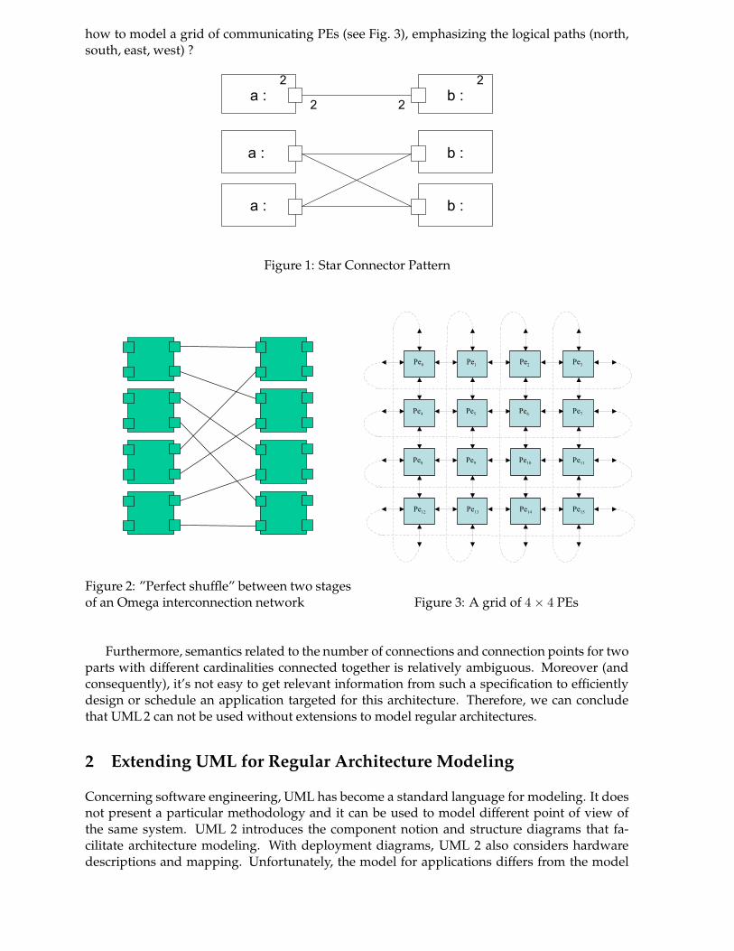
how to model a grid of communicating PEs (see Fig. 3), emphasizing the logical paths (north,south, east, west) ?
Figure 1: Star Connector Pattern
Figure 2: ”Perfect shuffle” between two stagesof an Omega interconnection network Figure 3: A grid of 4 × 4 PEs
Furthermore, semantics related to the number of connections and connection points for twoparts with different cardinalities connected together is relatively ambiguous. Moreover (andconsequently), it’s not easy to get relevant information from such a specification to efficientlydesign or schedule an application targeted for this architecture. Therefore, we can concludethat UML 2 can not be used without extensions to model regular architectures.
2 Extending UML for Regular Architecture Modeling
Concerning software engineering, UML has become a standard language for modeling. It doesnot present a particular methodology and it can be used to model different point of view ofthe same system. UML 2 introduces the component notion and structure diagrams that fa-cilitate architecture modeling. With deployment diagrams, UML 2 also considers hardwaredescriptions and mapping. Unfortunately, the model for applications differs from the model
for hardware. The same comment applies for the mapping of an application on a particularhardware, for example a System-on-Chip: we want to benefit from the component notion, andthe hierarchical constructs of the structural and behavioral diagrams for the hardware designas well as for the software design.
However, as we have shown in the previous section, factorization mechanisms proposedin UML structural diagrams can bring ambiguity in the models, and are not powerful enoughto be suited to our needs. Therefore, our approach consists in extending a subset of UML toenable the modeling of regular architectures. In [2], we have presented a hierarchical hardwarearchitecture model, with precise syntactic and semantic rules. The UML extensions we presentin this paper are integrated in this model.
The abstract syntax of our model is described by a MOF metamodel defined as an extensionof the UML 2 metamodel. The metamodeling brings a set of tools which will enable us tospecify our application and hardware architecture models using UML tools, to reuse functionaland physical IPs, to ensure refinements between abstraction levels via mapping rules, to ensureinteroperability between the different abstraction levels used in a same codesign, and to ensurethe opening to other tools, like verification tools, thought the use of standards. The concretesyntax is defined by a profile for UML 2. This profile is, for the moment, only based on UML 2class diagrams and internal structure diagrams 1. In this paper, we focus on the descriptionof the profile (there is almost a “one to one” equivalence between concepts introduced in themetamodel and stereotypes introduced in the profile).
Section 3 summaries the so-called “Y model approach” [6], and gives a brief recall on thebasics of our hardware architecture model and section 4 presents the mechanisms we introduceto model regular architectures.
3 The "Y Model" approach
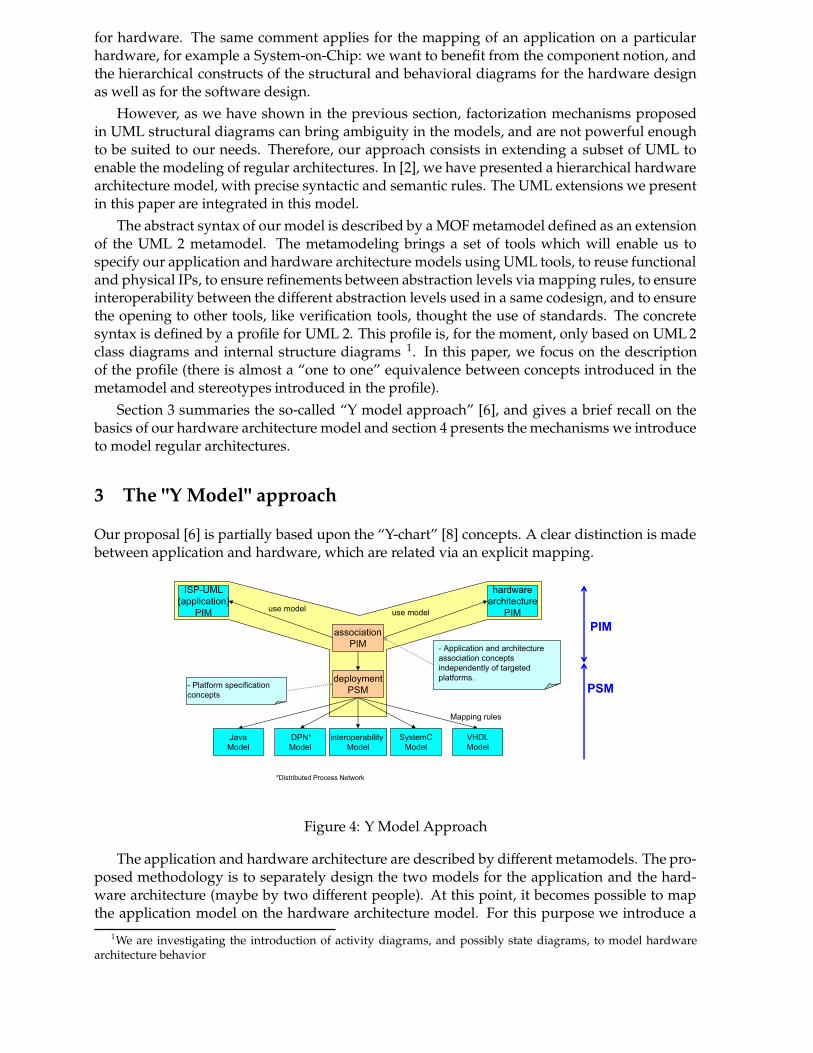
Our proposal [6] is partially based upon the “Y-chart” [8] concepts. A clear distinction is madebetween application and hardware, which are related via an explicit mapping.
ISP-UML
(application)
PIM
hardware
architecture
PIM
Mapping rules
use modeluse model
- Platform specification
concepts
association
PIM
deployment
PSM
- Application and architecture
association concepts
independently of targeted
platforms.
PIM
PSM
SystemC
Model
VHDL
Model
Java
Model
DPN*
Model
interoperability
Model
*Distributed Process Network
Figure 4: Y Model Approach
The application and hardware architecture are described by different metamodels. The pro-posed methodology is to separately design the two models for the application and the hard-ware architecture (maybe by two different people). At this point, it becomes possible to mapthe application model on the hardware architecture model. For this purpose we introduce a
1We are investigating the introduction of activity diagrams, and possibly state diagrams, to model hardwarearchitecture behavior
third metamodel, the so-called association metamodel, to express the associations between thefunctional components of the application model and the hardware components of the hardwaremodel. This third metamodel imports the first two metamodels.
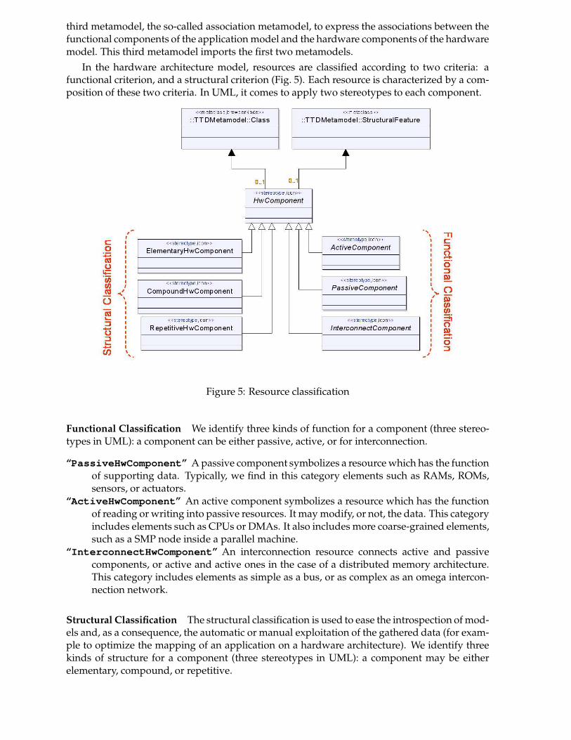
In the hardware architecture model, resources are classified according to two criteria: afunctional criterion, and a structural criterion (Fig. 5). Each resource is characterized by a com-position of these two criteria. In UML, it comes to apply two stereotypes to each component.
Figure 5: Resource classification
Functional Classification We identify three kinds of function for a component (three stereo-types in UML): a component can be either passive, active, or for interconnection.
“PassiveHwComponent” A passive component symbolizes a resource which has the functionof supporting data. Typically, we find in this category elements such as RAMs, ROMs,sensors, or actuators.
“ActiveHwComponent” An active component symbolizes a resource which has the functionof reading or writing into passive resources. It may modify, or not, the data. This categoryincludes elements such as CPUs or DMAs. It also includes more coarse-grained elements,such as a SMP node inside a parallel machine.
“InterconnectHwComponent” An interconnection resource connects active and passivecomponents, or active and active ones in the case of a distributed memory architecture.This category includes elements as simple as a bus, or as complex as an omega intercon-nection network.
Structural Classification The structural classification is used to ease the introspection of mod-els and, as a consequence, the automatic or manual exploitation of the gathered data (for exam-ple to optimize the mapping of an application on a hardware architecture). We identify threekinds of structure for a component (three stereotypes in UML): a component may be eitherelementary, compound, or repetitive.
“ElementaryHwComponent” An elementary component is a component without an internalstructural description. For example, it could be used in the case where we have a hard-ware IP for this component, or in the case where we don’t want to model the componentmore finely.
“CompoundHwComponent” A compound component is a component with an internal struc-ture description. A compound component can represent an “executable architecture”(fully defined architecture) or a part of an architecture that will be reused in other con-texts. A compound component may be defined with several hierarchy levels: it may bedescribed as the gathering of other “sub” compound components. The benefits of com-position are numerous, and they are not specific to our model: encapsulation of struc-tural details not needed at a given hierarchical level, reuse or repetition (in the case of a“RepetitiveHwComponent”) of predefined blocks to model other architectures...
“RepetitiveHwComponent” A repetitive component is a particular case of the compoundcomponent. The repetitive component structure contains a regular repetition of a singlecomponent. This kind of component is well suited to the modeling of regular parallelarchitectures. The next section will focus on the way to express such kind of architecturesusing a repetitive component.
4 Regular Hardware Architecture Modeling via Dependence Expres-sions
Basically, our proposal consists in using mechanisms similar to those we have used in the ap-plication model. Similiraty between concepts handled within these two models permits tounify and so simplify their understanding and use. This unification is possible as the modelingproblems encountered in the two models are actually the same: Expressing the repetition ofcomponents and the factorization of the dependences among them.
In the application model, these mechanisms are mainly used to express data parallelism inthe context of a “DataParallelComponent” [6].
In the hardware architecture model, the UML extensions we introduce enable us to define“iterators” over architectural elements: The “RepetitiveHwComponent”. The structure of a“RepetitiveHwComponent” contains only one instance of an hardware component, i.e. theinstance of the component that must be repeated. A RepetitiveHwComponent is characterizedby an iteration space, explicitely given or deduced from the specification of the component.
With the “MultiPort” concept, we allow to see a port as a collection of ports, or an arrayof ports, with possibly several dimensions and a size for each dimension.
Via the expression of dependence vectors, these two concepts enable to model complexconnection patterns such as a perfect shuffle (Fig. 2) or regular architectures such as a 16 × 16-PE grid (Fig. 3). Let us illustrate our subject with these two academic examples.
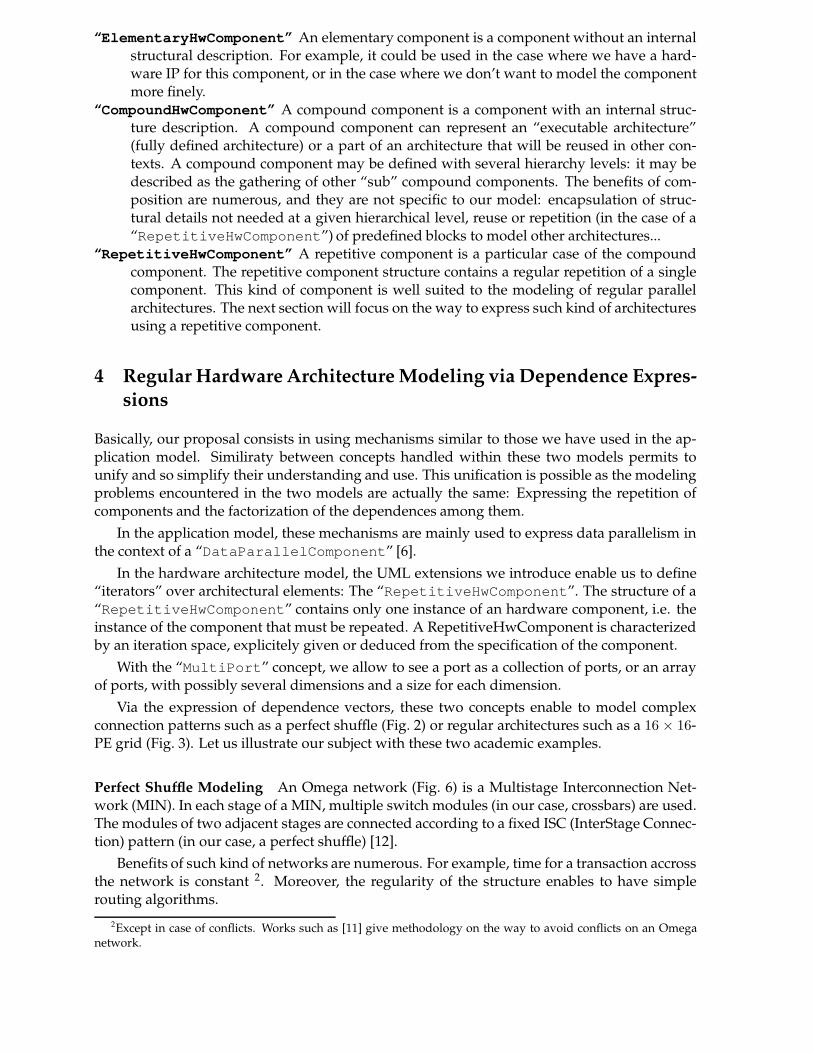
Perfect Shuffle Modeling An Omega network (Fig. 6) is a Multistage Interconnection Net-work (MIN). In each stage of a MIN, multiple switch modules (in our case, crossbars) are used.The modules of two adjacent stages are connected according to a fixed ISC (InterStage Connec-tion) pattern (in our case, a perfect shuffle) [12].
Benefits of such kind of networks are numerous. For example, time for a transaction accrossthe network is constant 2. Moreover, the regularity of the structure enables to have simplerouting algorithms.
2Except in case of conflicts. Works such as [11] give methodology on the way to avoid conflicts on an Omeganetwork.
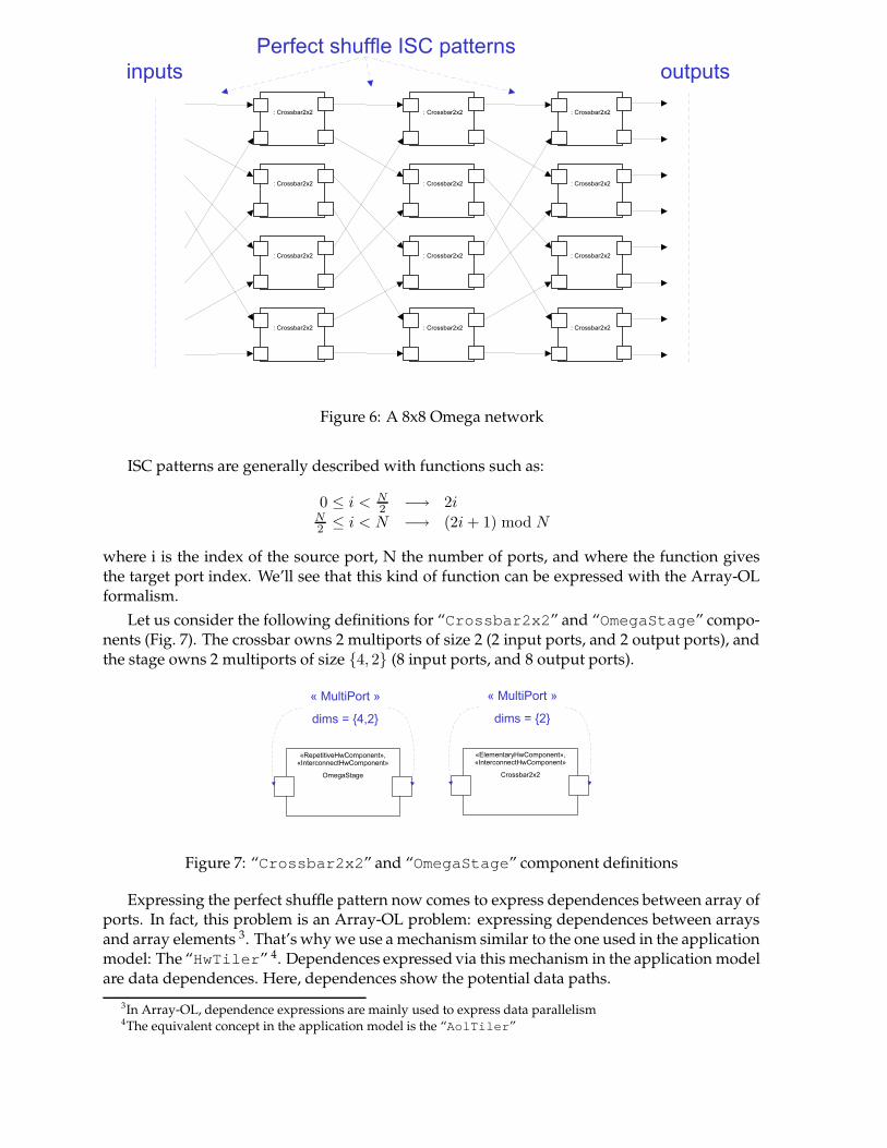
Figure 6: A 8x8 Omega network
ISC patterns are generally described with functions such as:
0 ≤ i < N
2−→ 2i
N
2≤ i < N −→ (2i + 1) mod N
where i is the index of the source port, N the number of ports, and where the function givesthe target port index. We’ll see that this kind of function can be expressed with the Array-OLformalism.
Let us consider the following definitions for “Crossbar2x2” and “OmegaStage” compo-nents (Fig. 7). The crossbar owns 2 multiports of size 2 (2 input ports, and 2 output ports), andthe stage owns 2 multiports of size {4, 2} (8 input ports, and 8 output ports).
Figure 7: “Crossbar2x2” and “OmegaStage” component definitions
Expressing the perfect shuffle pattern now comes to express dependences between array ofports. In fact, this problem is an Array-OL problem: expressing dependences between arraysand array elements 3. That’s why we use a mechanism similar to the one used in the applicationmodel: The “HwTiler” 4. Dependences expressed via this mechanism in the application modelare data dependences. Here, dependences show the potential data paths.
3In Array-OL, dependence expressions are mainly used to express data parallelism4The equivalent concept in the application model is the “AolTiler”
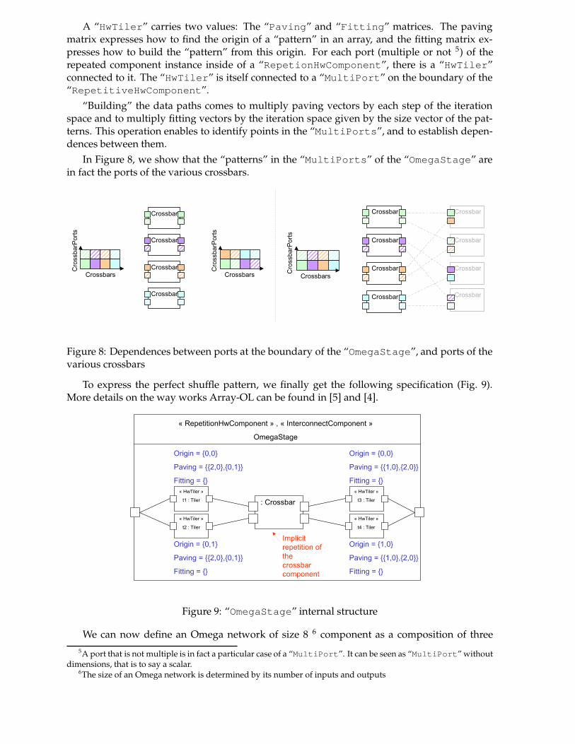
A “HwTiler” carries two values: The “Paving” and “Fitting” matrices. The pavingmatrix expresses how to find the origin of a “pattern” in an array, and the fitting matrix ex-presses how to build the “pattern” from this origin. For each port (multiple or not 5) of therepeated component instance inside of a “RepetionHwComponent”, there is a “HwTiler”connected to it. The “HwTiler” is itself connected to a “MultiPort” on the boundary of the“RepetitiveHwComponent”.
“Building” the data paths comes to multiply paving vectors by each step of the iterationspace and to multiply fitting vectors by the iteration space given by the size vector of the pat-terns. This operation enables to identify points in the “MultiPorts”, and to establish depen-dences between them.
In Figure 8, we show that the “patterns” in the “MultiPorts” of the “OmegaStage” arein fact the ports of the various crossbars.
Figure 8: Dependences between ports at the boundary of the “OmegaStage”, and ports of thevarious crossbars
To express the perfect shuffle pattern, we finally get the following specification (Fig. 9).More details on the way works Array-OL can be found in [5] and [4].
Figure 9: “OmegaStage” internal structure
We can now define an Omega network of size 8 6 component as a composition of three5A port that is not multiple is in fact a particular case of a “MultiPort”. It can be seen as “MultiPort” without
dimensions, that is to say a scalar.6The size of an Omega network is determined by its number of inputs and outputs
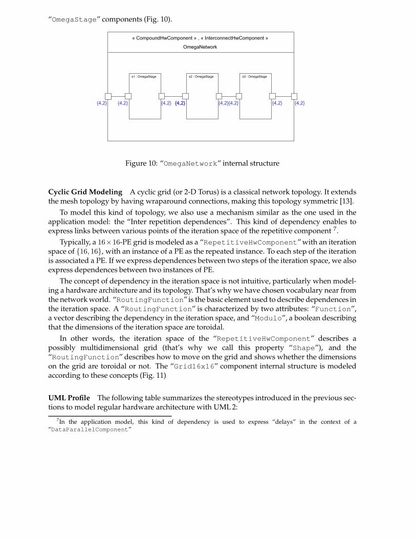
“OmegaStage” components (Fig. 10).
Figure 10: “OmegaNetwork” internal structure
Cyclic Grid Modeling A cyclic grid (or 2-D Torus) is a classical network topology. It extendsthe mesh topology by having wraparound connections, making this topology symmetric [13].
To model this kind of topology, we also use a mechanism similar as the one used in theapplication model: the “Inter repetition dependences”. This kind of dependency enables toexpress links between various points of the iteration space of the repetitive component 7.
Typically, a 16×16-PE grid is modeled as a “RepetitiveHwComponent” with an iterationspace of {16, 16}, with an instance of a PE as the repeated instance. To each step of the iterationis associated a PE. If we express dependences between two steps of the iteration space, we alsoexpress dependences between two instances of PE.
The concept of dependency in the iteration space is not intuitive, particularly when model-ing a hardware architecture and its topology. That’s why we have chosen vocabulary near fromthe network world. “RoutingFunction” is the basic element used to describe dependences inthe iteration space. A “RoutingFunction” is characterized by two attributes: “Function”,a vector describing the dependency in the iteration space, and “Modulo”, a boolean describingthat the dimensions of the iteration space are toroidal.
In other words, the iteration space of the “RepetitiveHwComponent” describes apossibly multidimensional grid (that’s why we call this property “Shape”), and the“RoutingFunction” describes how to move on the grid and shows whether the dimensionson the grid are toroidal or not. The “Grid16x16” component internal structure is modeledaccording to these concepts (Fig. 11)
UML Profile The following table summarizes the stereotypes introduced in the previous sec-tions to model regular hardware architecture with UML 2:
7In the application model, this kind of dependency is used to express “delays” in the context of a“DataParallelComponent”
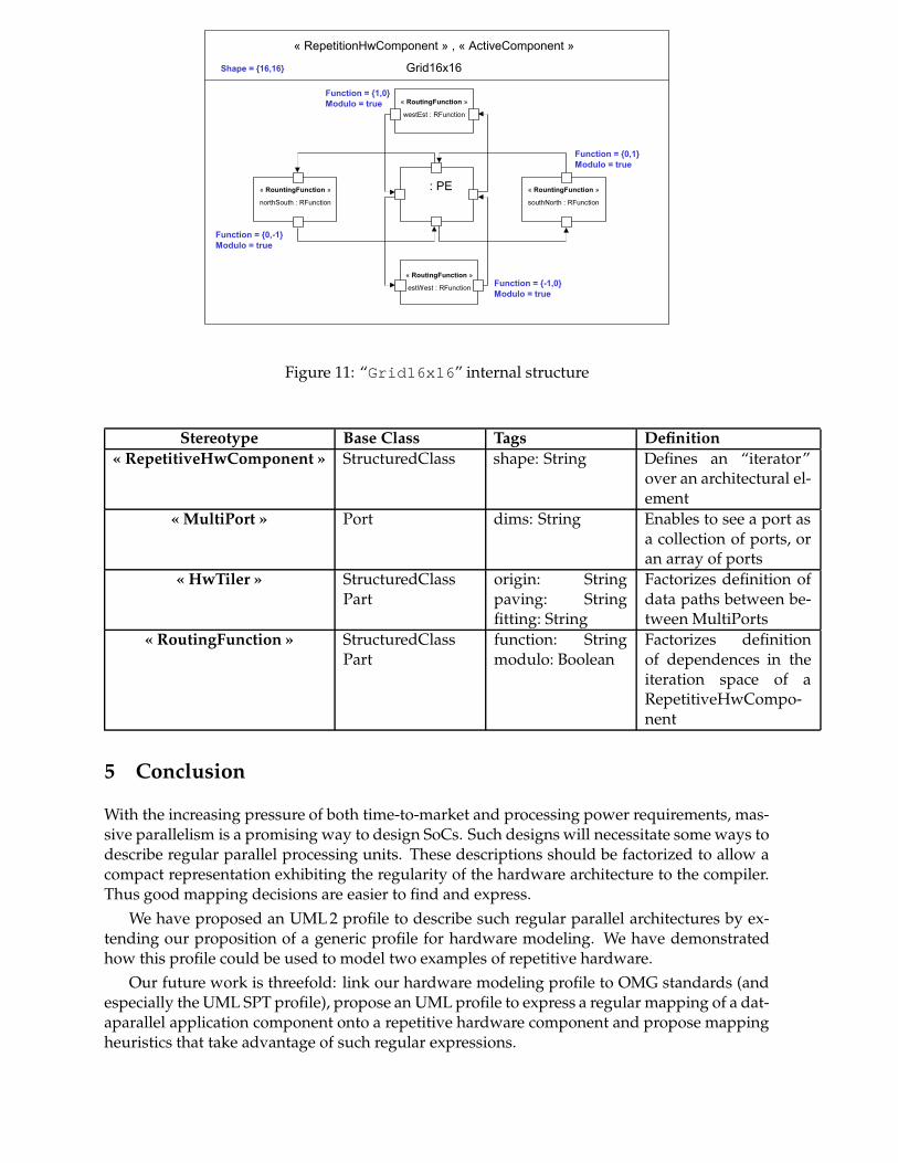
Figure 11: “Grid16x16” internal structure
Stereotype Base Class Tags Definition« RepetitiveHwComponent » StructuredClass shape: String Defines an “iterator”
over an architectural el-ement
« MultiPort » Port dims: String Enables to see a port asa collection of ports, oran array of ports
« HwTiler » StructuredClassPart
origin: Stringpaving: Stringfitting: String
Factorizes definition ofdata paths between be-tween MultiPorts
« RoutingFunction » StructuredClassPart
function: Stringmodulo: Boolean
Factorizes definitionof dependences in theiteration space of aRepetitiveHwCompo-nent
5 Conclusion
With the increasing pressure of both time-to-market and processing power requirements, mas-sive parallelism is a promising way to design SoCs. Such designs will necessitate some ways todescribe regular parallel processing units. These descriptions should be factorized to allow acompact representation exhibiting the regularity of the hardware architecture to the compiler.Thus good mapping decisions are easier to find and express.
We have proposed an UML 2 profile to describe such regular parallel architectures by ex-tending our proposition of a generic profile for hardware modeling. We have demonstratedhow this profile could be used to model two examples of repetitive hardware.
Our future work is threefold: link our hardware modeling profile to OMG standards (andespecially the UML SPT profile), propose an UML profile to express a regular mapping of a dat-aparallel application component onto a repetitive hardware component and propose mappingheuristics that take advantage of such regular expressions.
References
[1] Acotris (analyse et conception à objets temps réel pour implantation asyn-chrone/synchrone). http://www.acotris.c-s.fr/.
[2] Arnaud Cuccuru, Philippe Marquet, and Jean-Luc Dekeyser. UML 2 as an ADL : Hierar-chical hardware modeling. Technical report, INRIA, To appear.
[3] Lawrie D.A. Access and alignment of data in an array processor. IEEE Trans. Comput.,C-24(12):1145–1155, December 1975.
[4] Alain Demeure. Les modèles dans Array-OL: De la spécification d’applications de Traite-ment de Signal à la conception d’architectures et la génération des codes. In 5th AAAWorkshop on Algorithm Architectue Adequation, INRIA Rocquencourt, France, January 2000.
[5] Alain Demeure, Anne Lafage, Emmanuel Boutillon, Didier Rozzonelli, Jean-Claude Du-fourd, and Jean-Louis Marro. Array-OL : Proposition d’un formalisme tableau pour letraitement de signal multi-dimensionnel. In Gretsi, Juan-Les-Pins, France, September 1995.
[6] Cédric Dumoulin, Pierre Boulet, Jean-Luc Dekeyser, and Philippe Marquet. UML 2.0structure diagram for intensive signal processing application specification. Research Re-port RR-4766, INRIA, March 2003.
[7] Peter H. Feiler, Bruce Lewis, and Steve Vestal. The SAE avionics architecture descriptionlanguage (AADL) standard : A basis for model-based architecture-driven embedded sys-tems engineering. In RTAS 2003 Workshop on Model-Driven Embedded Systems, May 2003.
[8] D. D. Gajski and R. Kuhn. Guest editor introduction: New VLSI-tools. IEEE Computer,16(12):11–14, December 1983.
[9] Peter Green and Martyn Edwards. The modeling of embedded systems using hasoc. InDesign, Automation and Test in Europe Conference and Exhibition (DATE’02), Paris, France,March 2002.
[10] Peter Green and Martyn Edwards. Platform modeling with UML and systemc. In Forumon specification and Design Languages (FDL’02), September 2002.
[11] Wijshoff H.A.G. and Van Leeuwen J. On linear skewing schemes and d-ordered vectors.IEEE Trans. Comp., C-36(2):233–239, February 1987.
[12] Kai Hwang and Zhiwei Xu. Scalable Parallel Computing, chapter Buses, Crossbar, and Mul-tistage Switches, pages 301–302. WCB, 1998.
[13] Kai Hwang and Zhiwei Xu. Scalable Parallel Computing, chapter Network Topologies andProperties, pages 289–290. WCB, 1998.
[14] ITRS. Design, 2003 edition. http://public.itrs.net/, 2003.
[15] P. Lanusse, S.Gérard, and F.Terrier. Real-time modeling with UML : The ACCORD ap-proach. In UML 98 : Beyond the notation, Mulhouse, France, 1998.
[16] NEC Corporation. NEC unveils a new class of system LSI solutions, the dynamicallyreconfigurable processor LSI architecture, at microprocessor forum. http://www.nec.co.jp/press/en/0210/1601.html, 2002.
[17] Object Management Group, Inc., editor. (UML) Profile for Schedulability, Performance, andTime Specification. http://www.omg.org/cgi-bin/doc?ptc/2002-03-02/, May2002.

[18] Object Management Group, Inc., editor. (UML 2.0): Superstructure Draft Adopted Specifica-tion. http://www.omg.org/cgi-bin/doc?ptc/03-07-06/, July 2003.
[19] picoChip. Pc101 picoarray. http://www.picochip.com/technology/picoarray.
[20] Yves Sorel and Christophe Lavarenne. SynDEx Documentation Index. INRIA, 2000. http://www-rocq.inria.fr/syndex/doc/.
[21] Qiang Zhu, Akio Matsuda, Shinya Kuwamura, Tsuneo Nakata, and Minoru Shoji. Anobect-oriented design process for system-on-chip using UML. In Proceedings of the 15thinternational symposium on System Synthesis, pages 249–259, Kyoto, Japan, 2002.