um2124 user manual - stmicroelectronics...july 2017 docid029868 rev 2 1/37 um2124 user manual...
TRANSCRIPT

July 2017 DocID029868 Rev 2 1/37
www.st.com
UM2124 User manual
Getting started with the six-step firmware library for STM32 Nucleo boards based on STM32F microcontrollers
Introduction The six-step (trapezoidal) firmware is an easy-to-use and low requirement brushless scalar software library for three phase permanent magnet (PMSM) and brushless DC motors (BLDC) developed for STM32 microcontrollers.
The procedure to configure the six-step firmware library for STM32F microcontrollers and drive a BLDC motor in both open and closed loop is described in the following sections.
The current control method is based on sensorless mode but it is compatible with hall and encoder speed sensor modes.
The rotor position is reconstructed by BEMF detection.
The six-step library is written in the C programming language and it is based on STM32Cube library. The IDE tools supported are IAR Workbench, Keil and AC6. The core of this control algorithm is embedded inside the X-CUBE-SPN7 and X-CUBE-SPN8 firmware package available on the ST web site.
A prerequisite for using this library is basic knowledge of the C programming language, three phase motor drives and power inverter hardware. In-depth knowledge of STM32 functions is only required for customizing existing modules and for adding new ones for complete application development.
Contents UM2124
2/37 DocID029868 Rev 2
Contents
1 Acronyms and abbreviations ......................................................... 5
2 Features ........................................................................................... 6
2.1 Six-step software library in X-CUBE-SPN7 and X-CUBE-SPN8 packages ........................................................................................................ 6
2.2 Development tools ............................................................................ 6
2.3 Toolchains ......................................................................................... 7
2.3.1 Programming tools ............................................................................. 7
3 Implementation of six-step motor control algorithm in STM32 Nucleo microcontroller ............................................................................ 8
3.1 Introduction to BLDC theory .............................................................. 8
3.2 Rotor synchronization ....................................................................... 9
3.3 Motor driver control ........................................................................... 9
3.3.1 Current mode control .......................................................................... 9
3.3.2 Voltage mode control........................................................................ 11
3.3.3 Rotor speed measurement ............................................................... 11
3.3.4 Commutation, demagnetization delay and zero crossing event....... 13
3.3.5 Zero crossing detection method ....................................................... 15
3.3.6 Startup procedure ............................................................................. 16
4 X-CUBE-SPN7 and X-CUBE-SPN8 software expansion for STM32Cube ............................................................................................ 18
4.1 Firmware package architecture overview ........................................ 18
4.2 How to identify the six-step library version ...................................... 21
5 Getting started with the STM32 six-step firmware library .......... 22
6 Designing an application at user level using the firmware library31
6.1 Run a different BLDC motor ............................................................ 31
6.2 DAC settings for debug ................................................................... 34
6.3 How to use the API function for application development ............... 35
7 Revision history ............................................................................ 36
UM2124 List of tables
DocID029868 Rev 2 3/37
List of tables
Table 1: List of acronyms ............................................................................................................................ 5 Table 2: ROM and RAM requirements ....................................................................................................... 6 Table 3: Main mapped peripherals ........................................................................................................... 23 Table 4: Header file basic parameters ...................................................................................................... 23 Table 5: Header file advanced parameters (open loop control) ............................................................... 23 Table 6: Six-step advanced parameters for motor driving (current mode) ............................................... 25 Table 7: Six-step advanced parameters for motor driving (voltage mode) ............................................... 25 Table 8: Six-step general parameters for motor driving ........................................................................... 26 Table 9: Six-step firmware library not exported functions......................................................................... 27 Table 10: Six-step firmware library exported functions (APIs).................................................................. 27 Table 11: Document revision history ........................................................................................................ 36
List of figures UM2124
4/37 DocID029868 Rev 2
List of figures
Figure 1: BLDC motor control sequence .................................................................................................... 8 Figure 2: six-step phase voltage with BEMF sequence and PWM modulation .......................................... 8 Figure 3: Current mode control ................................................................................................................. 10 Figure 4: ETR function on current mode control ....................................................................................... 10 Figure 5: Voltage mode control ................................................................................................................. 11 Figure 6: Sinusoidal construction .............................................................................................................. 12 Figure 7: Trapezoidal construction ........................................................................................................... 12 Figure 8: High and low frequency timer signals ........................................................................................ 13 Figure 9: BEMF signal and zero crossing detection ................................................................................. 14 Figure 10: Demagnetization time .............................................................................................................. 14 Figure 11: Demagnetization: delay time (N=3) ......................................................................................... 15 Figure 12: Demagnetization: delay time (N=2) ......................................................................................... 15 Figure 13: BEMF measuring during the OFF-time and ADC sampling .................................................... 16 Figure 14: Alignment and ramp-up generation ......................................................................................... 17 Figure 15: Project workspace on IAR IDE ................................................................................................ 18 Figure 16: X-CUBE-SPN7 software architecture ...................................................................................... 19 Figure 17: X-CUBE-SPN8 software architecture ...................................................................................... 19 Figure 18: X-CUBE-SPN8 folder contents ................................................................................................ 20 Figure 19: six-step library version ............................................................................................................. 21 Figure 20: Acceleration rate and number of steps .................................................................................... 24 Figure 21: six-step firmware library component overview ........................................................................ 28 Figure 22: six-step main firmware routines: low priority task .................................................................... 29 Figure 23: six-step main firmware routines: medium priority task ............................................................ 29 Figure 24: six-step main firmware routines: high priority task .................................................................. 30 Figure 25: New motor running .................................................................................................................. 32 Figure 26: Motor successful initialization .................................................................................................. 33 Figure 27: Motor successful initialization zoom ........................................................................................ 33

UM2124 Acronyms and abbreviations
DocID029868 Rev 2 5/37
1 Acronyms and abbreviations Table 1: List of acronyms
Acronym Description
ACC acceleration constant
API application programming interface
ARR autoreload register
BEMF back electromotive force
BLDC brushless DC motor
DAC digital to analog converter
DC direct current
ETR external trigger
IDE integrated development environment
PMSM permanent magnet synchronous motor
PWM pulse-width modulation
UART universal asynchronous receiver transmitter

Features UM2124
6/37 DocID029868 Rev 2
2 Features
2.1 Six-step software library in X-CUBE-SPN7 and X-CUBE-SPN8 packages
The BLDC software library source code is available on www.st.com.
The six-step library is included in two different firmware packages called X-CUBE-SPN7 (tailored for X-NUCLEO-IHM07M1) and X-CUBE-SPN8 (tailored for X-NUCLEO-IHM08M1) which provide the compliance with STM32 ODE in STM32 Nucleo expansion platforms.
The main library features are:
supported trapezoidal six-step method
sensorless mode: BEMF (back electromagnetic force) voltage on the non-energized phase is monitored and used to trigger the commutation events
voltage mode: PWM duty cycle is set directly via a PWM 16-bit timer
current mode: the inner current loop and an external speed loop are used to control motor winding current. The output of a speed PI regulator becomes the input of the current loop that generates the PWM signal.
DC bus voltage measurement
fault handling (overcurrent)
one channel virtual DAC functionality for debugging.
Table 2: ROM and RAM requirements
Configuration ROM (Kbytes) RAM (Kbytes)
Six-step algorithm 7 0.5
X-CUBE-SPN7(1) 24 1
X-CUBE-SPN8(1) 24 1
Notes:
(1)It includes the STM32Cube library (ROM size: 12Kbytes). The remaining memory size is for the compliance with ST - STM32 ODE
2.2 Development tools
The BLDC firmware library is specific to some hardware platforms, in particular the X-CUBE-SPN7 with X-NUCLEO-IHM07M1 and the X-CUBE-SPN8 with X-NUCLEO-IHM08M1.
For evaluation purposes or new user development, it is recommended to use these hardware platforms together with STM32 Nucleo development board.
The X-CUBE-SPN7 is compatible with the following boards:
NUCLEO-F030R8
NUCLEO-F103RB
NUCLEO-F302R8
NUCLEO-F401RE
P-NUCLEO-IHM001
X-NUCLEO-IHM07M1
The X-CUBE-SPN8 is compatible with the following boards:

UM2124 Features
DocID029868 Rev 2 7/37
NUCLEO-F302R8
NUCLEO-F401RE
X-NUCLEO-IHM08M1
For the X-NUCLEO-IHM08M1 expansion board with 6-step control, keep the capacitor C5 mounted; in case of poor motor current regulation during startup, reduce its value. For further info refer to UM1996, "Getting started with X-NUCLEO-IHM08M1 low-voltage BLDC motor driver expansion board based on STL220N6F7 for STM32 Nucleo", available at www.st.com.
2.3 Toolchains
The library has been compiled through different integrated development environment (IDE) interfaces: IAR EWARM 7.4, Keil MDK-ARM v.5 and AC6 Workbench.
In the X-CUBE packages, it is possible to choose the right project workspace based on the MCU.
2.3.1 Programming tools
The six-step firmware library is preloaded in the motor control Nucleo pack (P-NUCLEO-IHM001).
For the other cases:
1 download the X-CUBE-SPN7 or X-CUBE-SPN8 firmware packages from www.st.com.
2 open the project workspace from the IDE tool available (IAR EWARM, Keil MDK-ARM v.5 or AC6 Workbench) choosing the right STM32 Nucleo development board.
3 change the motor and drive parameters
4 compile the firmware
5 upload the binary
When using the STM32 Nucleo development boards no additional programming tool (for instance external ST-Link, J-Link or equivalent) is needed as it is already embedded.

Implementation of six-step motor control algorithm in STM32 Nucleo microcontroller
UM2124
8/37 DocID029868 Rev 2
3 Implementation of six-step motor control algorithm in STM32 Nucleo microcontroller
3.1 Introduction to BLDC theory
A brushless three phase motor is made of a fixed part (a three winding set called "stator") and a mobile part (containing a permanent magnet called "rotor").
In BLDC motor control, the electrical cycle is subdivided into six commutation steps. For each step, the bus voltage is applied to one of the motor three phase windings whereas the ground is applied to a second winding. The third winding remains open. The successive steps are executed in the same way except that the motor phase winding changes to generate a rotating stator field (see Figure 1: "BLDC motor control sequence"): the red arrow shows the stator flux vector rotation of and the blue arrow shows its direction.
A BLDC motor has a trapezoidal BEMF (back electromagnetic force) induced into the motor phase windings. The BLDC drive is also called trapezoidal control because of the phase current shape. This control method allows having the maximum performance in terms of efficiency and minimum torque ripple since the motor is intrinsically built as BLDC. Figure 2: "six-step phase voltage with BEMF sequence and PWM modulation" shows the voltage applied to a phase (BEMF waveform and PWM modulation).
Figure 1: BLDC motor control sequence
Figure 2: six-step phase voltage with BEMF sequence and PWM modulation

UM2124 Implementation of six-step motor control algorithm in STM32 Nucleo microcontroller
DocID029868 Rev 2 9/37
3.2 Rotor synchronization
The BLDC drive is a synchronous control drive: the maximum efficiency is achieved if the commutation between two consecutive steps is performed only when the rotor is in the right spatial position, which occurs when the BEMF signal and the phase current are synchronized.
The following methods can be implemented to perform the rotor synchronization:
sensored drive, which uses position, Hall or encoder sensors to measure the rotor position.
sensorless drive, based on the BEMF detection. It analyzes the zero crossing of the floating phase BEMF signal to establish the commutation point. The match between the floating phase BEMF signal with respect to the ground point is used to generate the commutation between two consecutive steps in order to achieve the rotor synchronization.
The six-step firmware library (X-CUBE-SPN7 or X-CUBE-SPN8) is only based on sensorless mode, no position sensor is supported. The BEMF signal is analyzed for each step and a new commutation point is calculated step by step. This method allows rotor position synchronization with the drive control.
3.3 Motor driver control
The BLDC drive is performed modulating the phase voltage through a PWM sequence that is generated by two different control methods:
current mode (peak control): two control loops are needed, one inner and one outer. The inner loop generates, by hardware (with analog comparator), the PWM sequence for motor current regulation starting from an analog reference signal; this signal is generated by the outer loop that contains a digital PI regulator that compares the speed reference with the motor speed real feedback. It provides the torque control and inherent current limitation in the windings.
voltage mode: only one loop is needed, the PI regulator directly generates the PWM regulating the duty cycle value.
3.3.1 Current mode control
Figure 1: "BLDC motor control sequence" shows the current mode (peak current) driving method. The inner loop contains all the components to acquire the motor current, amplify and conditioning the signal to be compared with a reference value. This block output is directly connected to the ETR timer function (MCU features) that regulate the duration of the PWM signals. In this case, PWM Ton are managed by the ETR.

Implementation of six-step motor control algorithm in STM32 Nucleo microcontroller
UM2124
10/37 DocID029868 Rev 2
Figure 3: Current mode control
Figure 4: "ETR function on current mode control" shows how the ETR works during the normal operation. The red line is the motor current regulated at a fixed current reference (green). In blue the PWM signals managed by the ETR, each time the motor current reaches the current reference threshold, the ETR turns PWM signals off.
Figure 4: ETR function on current mode control
UM2124 Implementation of six-step motor control algorithm in STM32 Nucleo microcontroller
DocID029868 Rev 2 11/37
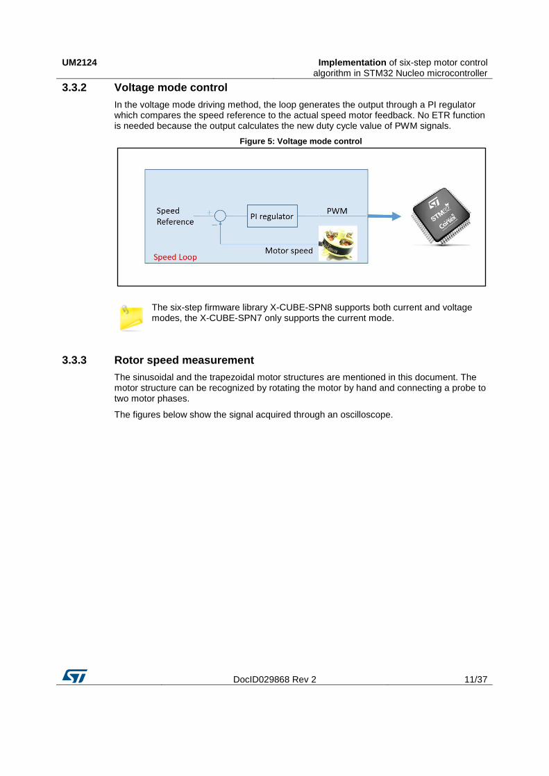
3.3.2 Voltage mode control
In the voltage mode driving method, the loop generates the output through a PI regulator which compares the speed reference to the actual speed motor feedback. No ETR function is needed because the output calculates the new duty cycle value of PWM signals.
Figure 5: Voltage mode control
The six-step firmware library X-CUBE-SPN8 supports both current and voltage modes, the X-CUBE-SPN7 only supports the current mode.
3.3.3 Rotor speed measurement
The sinusoidal and the trapezoidal motor structures are mentioned in this document. The motor structure can be recognized by rotating the motor by hand and connecting a probe to two motor phases.
The figures below show the signal acquired through an oscilloscope.

Implementation of six-step motor control algorithm in STM32 Nucleo microcontroller
UM2124
12/37 DocID029868 Rev 2
Figure 6: Sinusoidal construction
Figure 7: Trapezoidal construction
The rotor magnetic field produces a BEMF signal in the stator windings. If the motor is intrinsically sinusoidal or trapezoidal, the induced BEMF signals are periodic and their frequency is proportional to the frequency of the motor turns. The proportional coefficient is
UM2124 Implementation of six-step motor control algorithm in STM32 Nucleo microcontroller
DocID029868 Rev 2 13/37
the number of motor pole pairs; this number is used to calculate the mechanical speed of the motor: for instance, with 1000 Hz and 10 pole pairs (or 20 poles) the mechanical frequency is equal to 100 Hz.
The motor speed in rpm can consequently be calculated by measuring the electrical frequency of the motor:
Equation 1
𝑀𝑜𝑡𝑜𝑟𝑠𝑝𝑒𝑒𝑑(𝑟𝑝𝑚) =60
𝑃𝑜𝑙𝑒𝑝𝑎𝑖𝑟𝑛𝑢𝑚𝑏𝑒𝑟 × 𝑠𝑡𝑒𝑝𝑡𝑖𝑚𝑒(𝑠) × 6
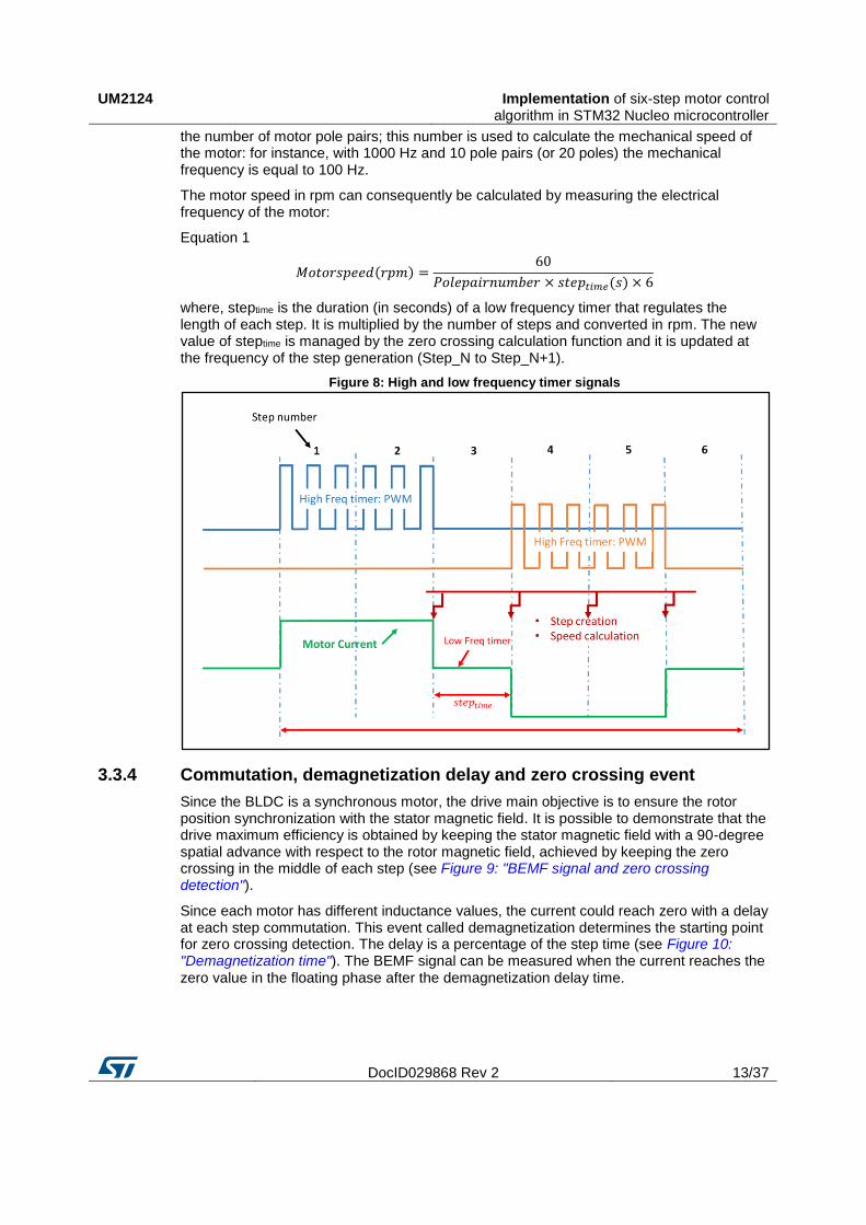
where, steptime is the duration (in seconds) of a low frequency timer that regulates the length of each step. It is multiplied by the number of steps and converted in rpm. The new value of steptime is managed by the zero crossing calculation function and it is updated at the frequency of the step generation (Step_N to Step_N+1).
Figure 8: High and low frequency timer signals
3.3.4 Commutation, demagnetization delay and zero crossing event
Since the BLDC is a synchronous motor, the drive main objective is to ensure the rotor position synchronization with the stator magnetic field. It is possible to demonstrate that the drive maximum efficiency is obtained by keeping the stator magnetic field with a 90-degree spatial advance with respect to the rotor magnetic field, achieved by keeping the zero crossing in the middle of each step (see Figure 9: "BEMF signal and zero crossing detection").
Since each motor has different inductance values, the current could reach zero with a delay at each step commutation. This event called demagnetization determines the starting point for zero crossing detection. The delay is a percentage of the step time (see Figure 10: "Demagnetization time"). The BEMF signal can be measured when the current reaches the zero value in the floating phase after the demagnetization delay time.

Implementation of six-step motor control algorithm in STM32 Nucleo microcontroller
UM2124
14/37 DocID029868 Rev 2
Figure 9: BEMF signal and zero crossing detection
Figure 10: Demagnetization time
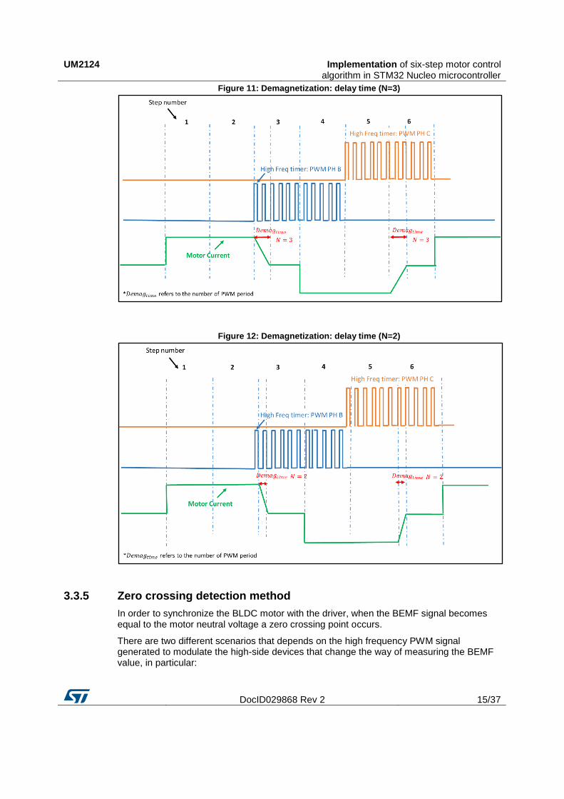
This method is managed through firmware (see Figure 11: "Demagnetization: delay time (N=3)"). Two different modes have been implemented, one is based on look-up-table and one is based on the current step time duration multiplied by a constant. The first is implemented in FW version 1.0, the other one only in version 1.1.0 (Please refer to the next section for further information). Figures Figure 11: "Demagnetization: delay time (N=3)" and Figure 12: "Demagnetization: delay time (N=2)" show the commutation delay at different N values: for instance, for N = 3 the delay time is 2 * T (switching period).
UM2124 Implementation of six-step motor control algorithm in STM32 Nucleo microcontroller
DocID029868 Rev 2 15/37
Figure 11: Demagnetization: delay time (N=3)
Figure 12: Demagnetization: delay time (N=2)
3.3.5 Zero crossing detection method
In order to synchronize the BLDC motor with the driver, when the BEMF signal becomes equal to the motor neutral voltage a zero crossing point occurs.
There are two different scenarios that depends on the high frequency PWM signal generated to modulate the high-side devices that change the way of measuring the BEMF value, in particular:
Implementation of six-step motor control algorithm in STM32 Nucleo microcontroller
UM2124
16/37 DocID029868 Rev 2
1. during PWM T-on time applied to the high-side switch, the motor neutral voltage becomes equal to the bus voltage divided by 2.
2. During PWM T-off time applied to the high-side switch, the motor neutral voltage becomes 0 V.
The zero crossing can be detected during both the on and the off time of the PWM signal.
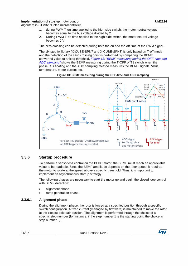
The six-step fw library (X-CUBE-SPN7 and X-CUBE-SPN8) is only based on T-off mode and the detection of the zero crossing point is performed by comparing the BEMF converted value to a fixed threshold. Figure 13: "BEMF measuring during the OFF-time and ADC sampling" shows the BEMF measuring during the T-OFF of T1 switch when the phase C is floating and the ADC sampling method measures the BEMF signals, Vbus, temperature, motor current etc.
Figure 13: BEMF measuring during the OFF-time and ADC sampling
3.3.6 Startup procedure
To perform a sensorless control on the BLDC motor, the BEMF must reach an appreciable value to be readable. Since the BEMF amplitude depends on the rotor speed, it requires the motor to rotate at the speed above a specific threshold. Thus, it is important to implement an asynchronous startup strategy.
The following phases are necessary to start the motor up and begin the closed loop control with BEMF detection:
alignment phase
ramp generation phase
3.3.6.1 Alignment phase
During the alignment phase, the rotor is forced at a specified position through a specific switch configuration. A fixed current (managed by firmware) is maintained to move the rotor at the closest pole pair position. The alignment is performed through the choice of a specific step number (for instance, if the step number 1 is the starting point, the choice is step number 6).
UM2124 Implementation of six-step motor control algorithm in STM32 Nucleo microcontroller
DocID029868 Rev 2 17/37
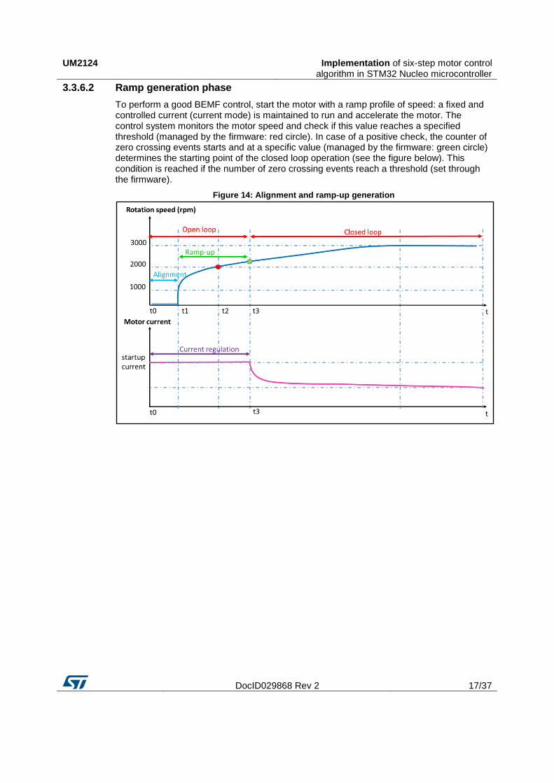
3.3.6.2 Ramp generation phase
To perform a good BEMF control, start the motor with a ramp profile of speed: a fixed and controlled current (current mode) is maintained to run and accelerate the motor. The control system monitors the motor speed and check if this value reaches a specified threshold (managed by the firmware: red circle). In case of a positive check, the counter of zero crossing events starts and at a specific value (managed by the firmware: green circle) determines the starting point of the closed loop operation (see the figure below). This condition is reached if the number of zero crossing events reach a threshold (set through the firmware).
Figure 14: Alignment and ramp-up generation

X-CUBE-SPN7 and X-CUBE-SPN8 software expansion for STM32Cube
UM2124
18/37 DocID029868 Rev 2
4 X-CUBE-SPN7 and X-CUBE-SPN8 software expansion for STM32Cube
4.1 Firmware package architecture overview
The firmware example in X-CUBE-SPN7 and X-CUBE-SPN8 is provided for three different IDE tools, IAR EWARM, Keil MDK-ARM, AC6 Workbench. In this case the IAR IDE workspace appears as shown in the following figure.
Figure 15: Project workspace on IAR IDE
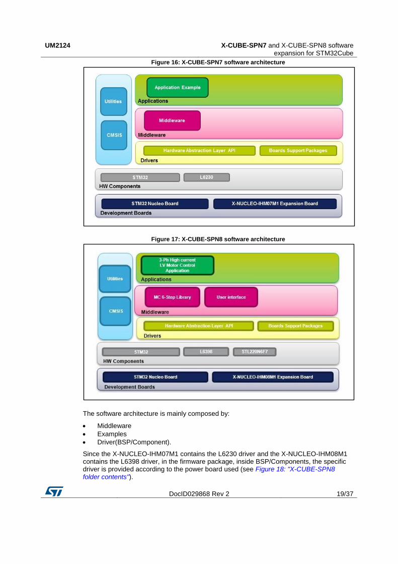
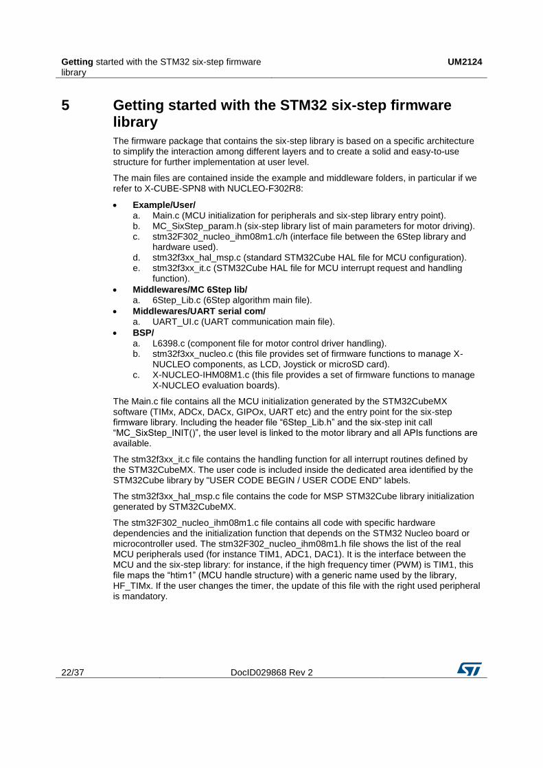
The firmware solution is built around three independent levels that can easily interact with each other as described in Figure 16: "X-CUBE-SPN7 software architecture" and Figure 17: "X-CUBE-SPN8 software architecture".
UM2124 X-CUBE-SPN7 and X-CUBE-SPN8 software expansion for STM32Cube
DocID029868 Rev 2 19/37
Figure 16: X-CUBE-SPN7 software architecture
Figure 17: X-CUBE-SPN8 software architecture
The software architecture is mainly composed by:
Middleware
Examples
Driver(BSP/Component).
Since the X-NUCLEO-IHM07M1 contains the L6230 driver and the X-NUCLEO-IHM08M1 contains the L6398 driver, in the firmware package, inside BSP/Components, the specific driver is provided according to the power board used (see Figure 18: "X-CUBE-SPN8 folder contents").

X-CUBE-SPN7 and X-CUBE-SPN8 software expansion for STM32Cube
UM2124
20/37 DocID029868 Rev 2
Figure 18: X-CUBE-SPN8 folder contents
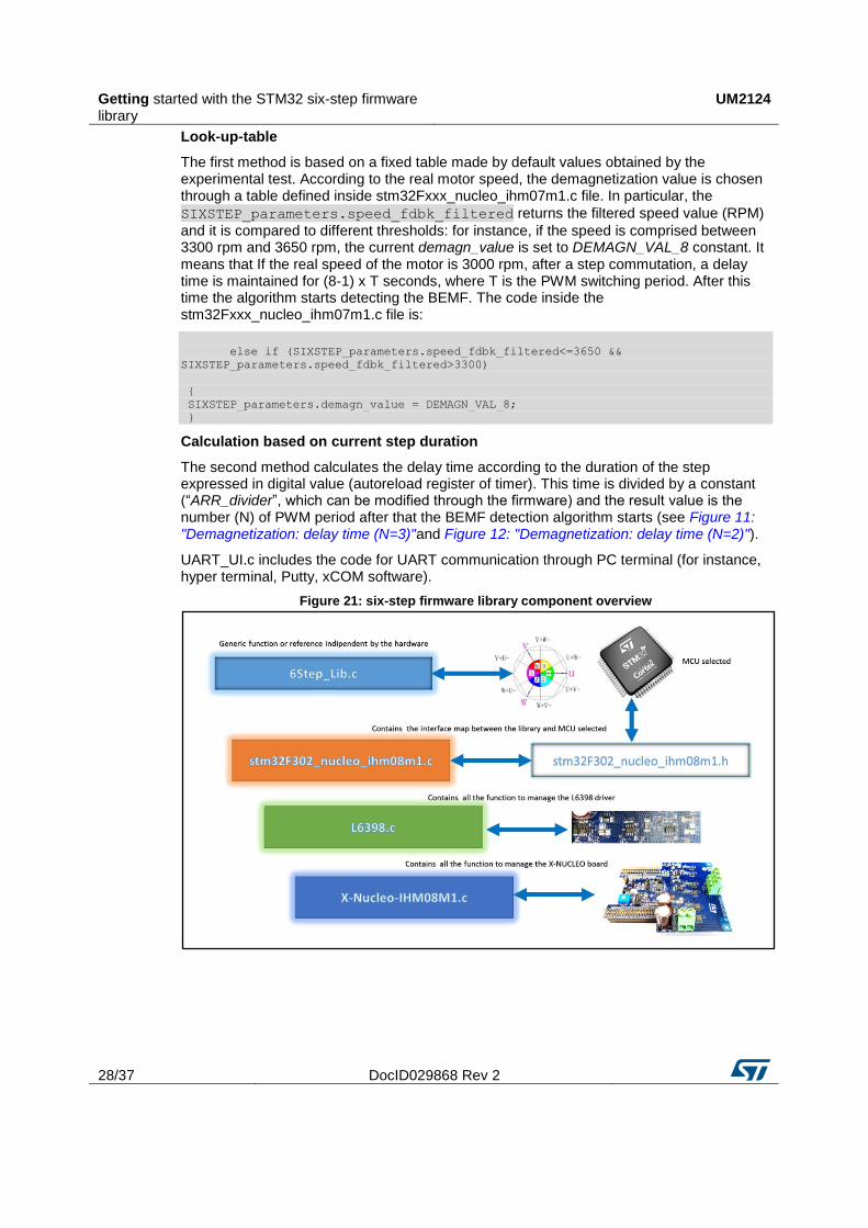
Middleware: the middleware provided in the X-CUBE-SPN7 and X-CUBE-SPN8 packages contains the motor control algorithm core: six-step library (6Step_Lib.c/h) and interface files (stm32f302_ihm0xm1.c/h). The interface file includes the map of STM32 MCU peripherals used (for instance, advanced TIMx, general TIMx, ADCx, DACx, UART etc.) to operate with the MC six-step library. This file must be updated according to the modification directly done or through STM32CubeMX software by the user, if channels or internal peripherals are modified with respect to the default configuration. At middlewares level a serial communication based on UART via an external PC terminal emulator has been included in the X-CUBE-SPN7 and X-CUBE-SPN8 packages (see the UART_UI.c/h and Figure 18: "X-CUBE-SPN8 folder contents").
Examples: the X-CUBE-SPN7 and X-CUBE-SPN8 packages contain an application layer for further code development. This folder is created with Cube MX software and it also contains the main file for firmware initialization (peripherals, MC_6Step and UART communication). In addition, a specific file (MC_SixStep_param.h) has been added to provide the complete list of parameters for the six-step library at application level. The stm32fxxx_it.c file contains the starting point for UART communication and defines all interrupt handlers.

UM2124 X-CUBE-SPN7 and X-CUBE-SPN8 software expansion for STM32Cube
DocID029868 Rev 2 21/37
4.2 How to identify the six-step library version
In order to identify the version of six-step firmware library it is recommended to open the “6Step_Lib.c” file and check for the versioning as shown in the following figure.
Figure 19: six-step library version
Getting started with the STM32 six-step firmware library
UM2124
22/37 DocID029868 Rev 2
5 Getting started with the STM32 six-step firmware library
The firmware package that contains the six-step library is based on a specific architecture to simplify the interaction among different layers and to create a solid and easy-to-use structure for further implementation at user level.
The main files are contained inside the example and middleware folders, in particular if we refer to X-CUBE-SPN8 with NUCLEO-F302R8:
Example/User/ a. Main.c (MCU initialization for peripherals and six-step library entry point). b. MC_SixStep_param.h (six-step library list of main parameters for motor driving). c. stm32F302_nucleo_ihm08m1.c/h (interface file between the 6Step library and
hardware used). d. stm32f3xx_hal_msp.c (standard STM32Cube HAL file for MCU configuration). e. stm32f3xx_it.c (STM32Cube HAL file for MCU interrupt request and handling
function).
Middlewares/MC 6Step lib/ a. 6Step_Lib.c (6Step algorithm main file).
Middlewares/UART serial com/ a. UART_UI.c (UART communication main file).
BSP/ a. L6398.c (component file for motor control driver handling). b. stm32f3xx_nucleo.c (this file provides set of firmware functions to manage X-
NUCLEO components, as LCD, Joystick or microSD card). c. X-NUCLEO-IHM08M1.c (this file provides a set of firmware functions to manage
X-NUCLEO evaluation boards).
The Main.c file contains all the MCU initialization generated by the STM32CubeMX software (TIMx, ADCx, DACx, GIPOx, UART etc) and the entry point for the six-step firmware library. Including the header file “6Step_Lib.h” and the six-step init call “MC_SixStep_INIT()”, the user level is linked to the motor library and all APIs functions are available.
The stm32f3xx_it.c file contains the handling function for all interrupt routines defined by the STM32CubeMX. The user code is included inside the dedicated area identified by the STM32Cube library by "USER CODE BEGIN / USER CODE END" labels.
The stm32f3xx_hal_msp.c file contains the code for MSP STM32Cube library initialization generated by STM32CubeMX.
The stm32F302_nucleo_ihm08m1.c file contains all code with specific hardware dependencies and the initialization function that depends on the STM32 Nucleo board or microcontroller used. The stm32F302_nucleo_ihm08m1.h file shows the list of the real MCU peripherals used (for instance TIM1, ADC1, DAC1). It is the interface between the MCU and the six-step library: for instance, if the high frequency timer (PWM) is TIM1, this file maps the “htim1” (MCU handle structure) with a generic name used by the library, HF_TIMx. If the user changes the timer, the update of this file with the right used peripheral is mandatory.
UM2124 Getting started with the STM32 six-step firmware library
DocID029868 Rev 2 23/37
The table below shows the list of the main peripherals mapped:
Table 3: Main mapped peripherals
Six-step library name MCU structure name
#define HF_TIMx htim1
#define LF_TIMx htim6
#define ADCx hadc1
#define REFx htim16
#define UART huart2
The MC_SixStep_param.h file contains all the parameters to configure the motor driving with the six-step algorithm (for instance the control type (current/voltage mode), the open loop initial current reference, BEMF threshold, speed PI regulator (Kp, Ki parameters), alignment time (msec), target speed (rpm) etc).
Table 4: Header file basic parameters
Constant name Description Unit / max. and typical
value
NUM_POLE_PAIRS Number of BLDC motor pole pairs 16 bit unsigned
DIRECTION Set the motor direction: (0) for CW or (1) for CCW. 0 or 1
TARGET_SPEED Target speed in the closed loop phase when the potentiometer is disabled
RPM, 16 bit unsigned
POTENTIOMETER Enable the potentiometer for speed regulation in closed loop (1 for enable). It doesn’t change the speed threshold control during the open loop phase set by default.
0 or 1
VOLTAGE_MODE Enable the voltage mode control. By default the current mode is enabled (voltage mode disabled).
0 or 1
Table 5: Header file advanced parameters (open loop control)
Constant name Description
Unit / max. and
typical value
STARTUP_CURRENT_REFERENCE(1)
Startup current reference. It is a digital value with the maximum value to be set by the UPPER_OUT_LIMIT parameter. The formula to calculate this value is:
𝑅𝑆𝐻𝑈𝑁𝑇(𝑜ℎ𝑚) × 𝐼𝑆𝐻𝑈𝑁𝑇(𝐴) × 𝑂𝑝𝐴𝑚𝑝𝐺𝑎𝑖𝑛3.3(𝑉)
× UPPER_OUT_LIMIT
16 bit unsigned
ACC Mechanical acceleration rate. This digital value identifies the slope of the acceleration during the time.
32bit unsigned,
RPM/s
MINIMUM_ACC Minimum mechanical acceleration rate (for high inertia motor)
32bit unsigned,
RPM/s

Getting started with the STM32 six-step firmware library
UM2124
24/37 DocID029868 Rev 2
Constant name Description
Unit / max. and
typical value
NUMBER_OF_STEPS(1)
Maximum number of steps for acceleration during the open loop phase. If the closed loop validation is not completed at the end of this time a speed fault error will be generated
16bit unsigned
TIME_FOR_ALIGN Time for alignment msec, 16bit
unsigned
BUTTON_DELAY Delay time to enable push button for new command
msec, 32bit
unsigned
NUMBER_ZCR Number of zero crossing events in sequence for closed loop validation
32bit unsigned
Notes:
(1)See Figure 20: "Acceleration rate and number of steps": the graphs show the different ACC values. At each step number a new speed value is generated. A “SPEED_FDBK” error is generated if the system reaches the maximum NUMBER_OF_STEPS before the closed loop starts (for instance, if the ACC value is too low to reach the target speed).
Figure 20: Acceleration rate and number of steps

UM2124 Getting started with the STM32 six-step firmware library
DocID029868 Rev 2 25/37
Table 6: Six-step advanced parameters for motor driving (current mode)
Closed loop control Current mode Unit
SPEED_LOOP_TIME Time for new execution of speed loop msec, 16 bit
unsigned
KP_GAIN Proportional term of PI regulator 16 bit signed
KI_GAIN Integral term of PI regulator 16 bit signed
KP_DIV Divider for proportional term of PI regulator 16 bit signed, power of two
KI_DIV Divider for integral term of PI regulator 16 bit signed, power of two
LOWER_OUT_LIMIT (1) Minimum output value of PI regulator (minimum current reference for comparator)
16 bit signed
UPPER_OUT_LIMIT Maximum output value of PI regulator (maximum current reference for comparator)
16 bit signed
MAX_POT_SPEED Maximum Speed regulated by potentiometer rpm, 16 bit unsigned
MIN_POT_SPEED Minimum Speed regulated by potentiometer rpm, 16 bit unsigned
VAL_POT_SPEED_DIV(2) Validation potentiometer speed divider Constant
INITIAL_DEMAGN_DELAY Initial value for demagnetization time for BEMF detection. It is a multiple of high frequency PWM signal
16 bit unsigned
Notes:
(1)The reference value of the comparator (embedded in the board) is calculated according to the UPPER_OUT_LIMIT of the PI regulator:
𝐶𝑢𝑟𝑟𝑒𝑛𝑡_𝑅𝑒𝑓𝑒𝑟𝑒𝑛𝑐𝑒_𝑆𝑒𝑡𝑣𝑎𝑙𝑢𝑒 =𝑆𝐼𝑋𝑆𝑇𝐸𝑃_𝑝𝑎𝑟𝑎𝑚𝑒𝑡𝑒𝑟𝑠. 𝐶𝑢𝑟𝑟𝑒𝑛𝑡_𝑅𝑒𝑓𝑒𝑟𝑒𝑛𝑐𝑒
𝑈𝑃𝑃𝐸𝑅_𝑂𝑈𝑇_𝐿𝐼𝑀𝐼𝑇𝑥𝐴𝑅𝑅𝑇𝐼𝑀𝑥
, where SIXSTEP_parameters.Current_Reference is the output of the PI regulator and ARRTIMxis the autoreload
value of a base timer. In case Current_Reference_Setvalue = ARRTIMx, the analog signal (as input of comparator) is generated at 3V3 constant and it is compared to the current real measurement.
(2)At the startup the potentiometer is used to set the speed threshold for closed loop validation. It is possible to increase this value (VAL_POT_SPEED_DIV) to reduce the maximum threshold value respect to the maximum speed.
Table 7: Six-step advanced parameters for motor driving (voltage mode)
Closed loop control Voltage mode Unit
KP_GAIN_VM(1) Proportional term of PI regulator 16 bit signed
KI_GAIN_VM Integral term of PI regulator 16 bit signed
KP_DIV_VM Divider for proportional term of PI regulator
16 bit signed, power of two
KI_DIV_VM Divider for integral term of PI regulator
16 bit signed, power of two
LOWER_OUT_LIMIT_VM Minimum output value of PI regulator
16 bit signed
UPPER_OUT_LIMIT_VM Maximum output value of PI regulator
16 bit signed

Getting started with the STM32 six-step firmware library
UM2124
26/37 DocID029868 Rev 2
Closed loop control Voltage mode Unit
DUTY_CYCLE_INIT_VALUE (2)
Duty cycle initial value 16 bit unsigned (max PWM
ARR)
Notes:
(1)This parameter is available for X-CUBE-SPN8 only (2)The maximum duty cycle value is limited by the autoreload (ARR) register of high frequency timer.
Table 8: Six-step general parameters for motor driving
Closed loop control Voltage mode Unit
SYNCHRONOUS_RECTIFICATION(1) Enable the complementary output of high frequency leg
0 or 1
BEMF_THRSLD_DOWN BEMF threshold for down direction 16 bit
unsigned, ADC value
BEMF_THRSLD_UP BEMF threshold for up direction 16 bit
unsigned, ADC value
FILTER_DEEP Number of elements for speed or bemf filtering
16 bit unsigned
HFBUFFERSIZE Buffer size for potentiometer value filtering at the High-frequency ADC conversion
16 bit unsigned
ADC_SPEED_TH Fixed threshold to change the target speed 16 bit
unsigned
BEMF_CONSEC_DOWN_MAX Maximum value of BEMF Consecutive Threshold Falling Crossings Counter in closed loop (Motor stall detection)
8 bit unsigned
BEMF_CNT_EVENT_MAX Maximum number of BEMF Counter in open loop (Motor stall detection)
16 bit unsigned
GPIO_ZERO_CROSS Enable the GPIO toggling output for zero crossing detection
0 or 1
GPIO_COMM Enable the GPIO toggling output for commutation detection.
0 or 1
DEMO_START_TIME (2) Time to keep the motor in run mode msec, 16 bit
unsigned
DEMO_STOP_TIME Time (msec) to keep the motor in stop mode
msec, 16 bit unsigned
Notes:
(1)This parameter is available for X-CUBE-SPN8 only (2)This time is available if the DEMO mode is selected during the compiling phase

UM2124 Getting started with the STM32 six-step firmware library
DocID029868 Rev 2 27/37
6Step_Lib.c contains the six-step library and the main functions are listed in the following tables.
Table 9: Six-step firmware library not exported functions
Function Result
MC_SixStep_TABLE() Sets the peripherals (TIMx, GPIO etc.) for each step
MC_SixStep_ARR_step() Generates the ARR value for low frequency TIM during start-up
MC_SixStep_Ramp_Motor_calc() Calculates the acceleration profile step by step for motor during start-up
MC_SixStep_NEXT_step() Generates the next step number according to the direction (CW or CCW)
MC_Task_Speed() Speeds loop with PI regulator
MC_Bemf_Delay() Calculates the demagnetization delay time
Table 10: Six-step firmware library exported functions (APIs)
Function Result
MC_SixStep_INIT() Initializes the main variables for motor driving from MC_SixStep_param.h
MC_SixStep_RESET() Resets all variables used for 6Step control algorithm
MC_StartMotor() Starts the motor
MC_StopMotor() Stops the motor
MC_Set_Speed() Sets the new motor speed value
MC_EXT_button_SixStep() Handles the push button event
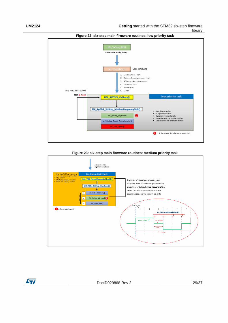
The exported APIs functions are inside the header file 6Step_Lib.h. It contains also all the variables and structures for the six-step algorithm. At the base of the MC driver, three main tasks run at different frequencies and with different priority levels, according to the specific function to cover, in particular (see Figure 22: "six-step main firmware routines: low priority task", Figure 23: "six-step main firmware routines: medium priority task" and Figure 24: "six-step main firmware routines: high priority task"):
1. High priority task: it is dedicated to the high frequency function (advanced TIMx PWM generation, ADC reading) and it is managed at the highest priority. This frequency can be modified through the STM32CubeMX software, i.e. TIM1_ARR.
2. Medium priority task: it is dedicated to the medium frequency function (general TIMx for step timing) and it is managed at medium priority. This frequency can be modified through the STM32CubeMX software, i.e. TIM6_ARR (for STM32F302-Nucleo).
3. Low priority task: it is dedicated to the low frequency function (SysTick timer for Speed Loop timing) and it is managed at the lowest priority. The MC_SysTick_SixStep_MediumFrequencyTask() is called at SysTick frequency (1 msec), while the speed loop function is managed by SPEED_LOOP_TIME (msec) defined in the MC_SixStep_param.h file.
The MC_Bemf_Delay() is implemented in two different modes:
look-up-table (six-step lib vers. 1.0.0)
calculation based on current step duration (six-step lib vers. 1.1.0)
Getting started with the STM32 six-step firmware library
UM2124
28/37 DocID029868 Rev 2
Look-up-table
The first method is based on a fixed table made by default values obtained by the experimental test. According to the real motor speed, the demagnetization value is chosen through a table defined inside stm32Fxxx_nucleo_ihm07m1.c file. In particular, the
SIXSTEP_parameters.speed_fdbk_filtered returns the filtered speed value (RPM)
and it is compared to different thresholds: for instance, if the speed is comprised between 3300 rpm and 3650 rpm, the current demagn_value is set to DEMAGN_VAL_8 constant. It means that If the real speed of the motor is 3000 rpm, after a step commutation, a delay time is maintained for (8-1) x T seconds, where T is the PWM switching period. After this time the algorithm starts detecting the BEMF. The code inside the stm32Fxxx_nucleo_ihm07m1.c file is:
else if (SIXSTEP_parameters.speed_fdbk_filtered<=3650 &&
SIXSTEP_parameters.speed_fdbk_filtered>3300)
{
SIXSTEP_parameters.demagn_value = DEMAGN_VAL_8;
}
Calculation based on current step duration
The second method calculates the delay time according to the duration of the step expressed in digital value (autoreload register of timer). This time is divided by a constant (“ARR_divider”, which can be modified through the firmware) and the result value is the number (N) of PWM period after that the BEMF detection algorithm starts (see Figure 11: "Demagnetization: delay time (N=3)"and Figure 12: "Demagnetization: delay time (N=2)").
UART_UI.c includes the code for UART communication through PC terminal (for instance, hyper terminal, Putty, xCOM software).
Figure 21: six-step firmware library component overview
UM2124 Getting started with the STM32 six-step firmware library
DocID029868 Rev 2 29/37
Figure 22: six-step main firmware routines: low priority task
Figure 23: six-step main firmware routines: medium priority task

Getting started with the STM32 six-step firmware library
UM2124
30/37 DocID029868 Rev 2
Figure 24: six-step main firmware routines: high priority task

UM2124 Designing an application at user level using the firmware library
DocID029868 Rev 2 31/37
6 Designing an application at user level using the firmware library
6.1 Run a different BLDC motor
The X-CUBE-SPN7 and X-CUBE-SPN8 software expansion provided for X-NUCLEO-IHM07M1 and X-NUCLEO-IHM08M1 power boards are configured for low inductance/high speed motor by default. Since each motor has its specifications, the X-CUBE firmware packages are deisgned to simplify the way of spinning different kinds of motors through few changes.
A header file (MC_SixStep_param.h) includes several parameters in two sections: basic and advanced.
In the first one, it is possible to change the main parameters: for instance, motor pole pairs, clockwise or counterclockwise motor direction, target speed or potentiometer selection.
In the advance section, instead, it is possible to set the PI parameters, define the alignment time or the acceleration rate during startup, change the zero crossing threshold and a lot of parameters useful to the system fine tuning.
For better understand how to spin a generic BLDC motor, the procedure suggested is the following (in this case it refers to the X-NUCLEO-IHM08M1 expansion board plus the NUCLEO-F302R8 MCU board):
1. open the X-CUBE-SPN8 firmware package related to the NUCLEO-F302R8 board 2. open the MC_SixStep_param.h file and set the main parameters, in particular:
a. motor pole pairs b. STARTUP_CURRENT_REFERENCE c. ACC (for high inertia motor significantly reduce the default value) d. TIME_FOR_ALIGN e. MIN_POT_SPEED
3. connect two voltage passive probes to the default MCU pin (PC7 and PC10) for zero crossing and commutation event monitoring
4. compile the code and upload it into the STM32 Nucleo board 5. rotate the potentiometer at the minimum value 6. power on the X-NUCLEO board and press the blue button on the STM32 Nucleo
board.
If the values modified above are correct and the default parameters are good for the current motor connected, the system starts as shown in the following figure.
Designing an application at user level using the firmware library
UM2124
32/37 DocID029868 Rev 2
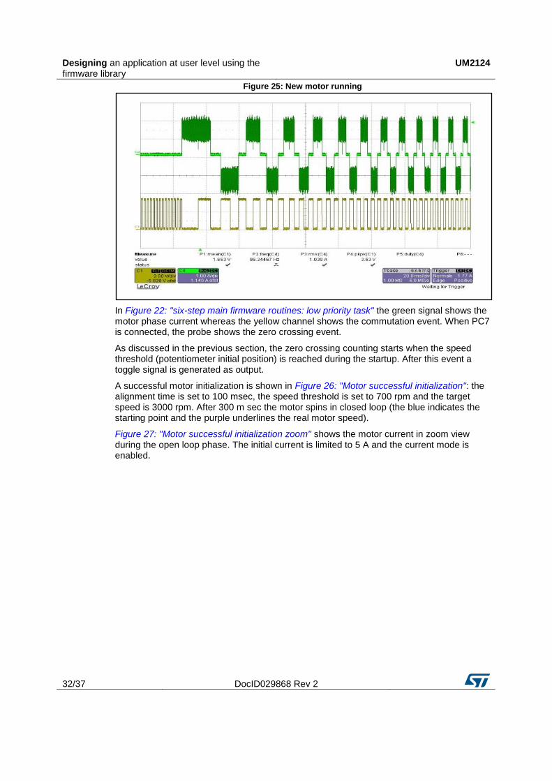
Figure 25: New motor running
In Figure 22: "six-step main firmware routines: low priority task" the green signal shows the motor phase current whereas the yellow channel shows the commutation event. When PC7 is connected, the probe shows the zero crossing event.
As discussed in the previous section, the zero crossing counting starts when the speed threshold (potentiometer initial position) is reached during the startup. After this event a toggle signal is generated as output.
A successful motor initialization is shown in Figure 26: "Motor successful initialization": the alignment time is set to 100 msec, the speed threshold is set to 700 rpm and the target speed is 3000 rpm. After 300 m sec the motor spins in closed loop (the blue indicates the starting point and the purple underlines the real motor speed).
Figure 27: "Motor successful initialization zoom" shows the motor current in zoom view during the open loop phase. The initial current is limited to 5 A and the current mode is enabled.

UM2124 Designing an application at user level using the firmware library
DocID029868 Rev 2 33/37
Figure 26: Motor successful initialization
Figure 27: Motor successful initialization zoom
Designing an application at user level using the firmware library
UM2124
34/37 DocID029868 Rev 2
In case of different current views, unsuccessful motor iniziatization or fault (visible through the SIXSTEP_parameters.STATUS variable), it is suggested to adjust the parameters mentioned above as follows:
Current (peak) control during the open loop
1. check if TIME_FOR_ALIGN (alignment time) has the right duration to align the motor2. check if the NUM_POLE_PAIRS is correct3. check STARTUP_CURRENT_REFERENCE (current peak threshold) during the open
loop stage. In case the motor doesn’t move or stalls, increase this value. If this valueis too big, an OVERCURRENT error occurs disabling the PWMs.
4. check if the ACC (acceleration time) is too big: in case of big inertia, reduce the valueto have a smooth start in more time. If this parameter is too small, the speed thresholdfor closed loop validation might never be reached and a STARTUP_FAILURE erroroccurs.
5. check the number NUMBER_ZCR (zero crossing event) for open loop end and closedloop validation phase.
6. plot the zero crossing (ZC) and step commutation event through the default GPIO pin(for instance, PC7 and PC10, GPIO_COMM and GPIO_ZERO_CROSS set to 1).When the ZC signal appears, the speed is validated and the counting of ZCconsecutive events (n_zcr_startup ++) is started. If this number reaches theNUMBER_ZCR consecutively, the closed loop control starts. In case of noconsecutive ZC detection the algorithm resets the counter (n_zcr_startup = 0) andincrease another counter (cnt_bemf_event ++). This last counter generates aSTARTUP_BEMF_FAILURE if it reaches the BEMF_CNT_EVENT_MAX.
7. reduce the potentiometer to decrease the speed threshold for closed loop validation(this control is always enabled also if the potentiometer parameter is set to 0, but inthis case it doesn’t provide speed change during the closed loop).
Voltage control during the open loop
The procedure is the same as the one shown in the previous section, except for point 3, which is replaced by the following step:
check the DUTY_CYCLE_INIT_VALUE which sets the initial duty cycle value fixed for the entire open loop phase. In case the motor doesn’t start, increase this value up to the high frequency PWM autoreload value (see main.c file, inside the TIMx configuration).
Closed loop control (current and voltage mode)
Check the KP_GAIN and KI_GAIN (current mode) or KP_GAIN_VM and KI_GAIN_VM (voltage mode) and plot the phase current to see the PI regulator reaction during the transition from open to closed loop and during the speed change (for instance, using the potentiometer). These values are not calculated by default and it is suggested to modify them during the test.
In case of overcurrent error, reduce the reaction of the PI regulator with lower values of Kp and Ki.
6.2 DAC settings for debug
For debugging, it is possible to use the DAC peripheral and configure the six-step library to drive the signal. The function SET_DAC_value (dac_value) allows converting the variable “dac_value” in 16 bit format (with no sign) in analog signal so it is possible to monitor the motor speed (set by default) or the potentiometer value through an external oscilloscope attached to the configured pin. By default PA4 pin is configured, it is accessible through the ST morpho connector and it is typically connected to DAC_CH1 (NUCLEO-F302R8). If the user chooses a different pin or peripheral, the stm32Fxxx_nucleo_ihm0xm1.h file must be
UM2124 Designing an application at user level using the firmware library
DocID029868 Rev 2 35/37
modified as described in Section 5: "Getting started with the STM32 six-step firmware library" (the DAC peripheral is on by default):
#define DAC_ENABLE 1
#define DACx hdac
#define DACx_CH DAC1_CHANNEL_1
#define DACx_ALIGN DAC_ALIGN_12B_L
6.3 How to use the API function for application development
In case of code development the user level is simplified with several APIs provided by the six-step library. For instance, the main APIs exported are mentioned in Table 11: "Six-step firmware library exported functions (APIs)":
MC_SixStep_INIT()
MC_SixStep_RESET()
MC_StartMotor()
MC_StopMotor()
MC_Set_Speed(new_speed)
MC_EXT_button_SixStep()
These functions are available at application layer (main.c) and can start or stop the motor or change the speed during the normal operation.
The MC_SixStep_INIT() initializes the six-step library and it is normally added in the first lines of the main.c file, after MCU peripherals configuration. Thus, the motor control algorithm is configured and ready to start. No input parameter is required.
The MC_SixStep_RESET resets all the main variables with the default values used for the six-step algorithm. It is called inside the MC_StopMotor() command: for instance, if a fault occurs or in case of control manual stop . No input parameter is required.
The MC_StartMotor() is the main command used to start the six-step algorithm; for instance, the PWM timer, the ADC conversions, the low frequency timer etc. No input parameter is required.
The MC_StopMotor() is the main command used to stop the six-step algorithm: for instance, the PWM timer, the ADC conversions, the low frequency timer etc. When the control has been disabled, the MC_SixStep_RESET is called. No input parameter is required.
The MC_Set_Speed (new_speed) is the main command used to set a new speed value for the motor during the closed loop stage. The input variable is defined as 16 bit unsigned and it is expressed in RPM unit. This parameter is used only if the potentiometer parameter is set to 0. No ramp profile is generated.
The MC_EXT_button_SixStep() is the command called by the HAL_GPIO_EXTI_Callback(), see the file stm32Fxxx_nucleo_ihm0xm1.c associated to an external push button. It sends a start or a stop motor function on the basis of the control previous status: for instance, if the six-step algorithm is in run state, it stops the control; if it is in idle state, it sends a start motor function.

Revision history UM2124
36/37 DocID029868 Rev 2
7 Revision history Table 11: Document revision history
Date Version Changes
09-Nov-2016 1 Initial release.
05-Jul-2017 2
In Section 2.2: "Development tools": added suggestions for FOC settings (C3, C5 and C7 capacitors).
Throughout text: added references to X-CUBE-SPN7 and X-CUBE-SPN8.

UM2124
DocID029868 Rev 2 37/37
IMPORTANT NOTICE – PLEASE READ CAREFULLY
STMicroelectronics NV and its subsidiaries (“ST”) reserve the right to make changes, corrections, enhancements, modifications, and improvements to ST products and/or to this document at any time without notice. Purchasers should obtain the latest relevant information on ST products before placing orders. ST products are sold pursuant to ST’s terms and conditions of sale in place at the time of order acknowledgement.
Purchasers are solely responsible for the choice, selection, and use of ST products and ST assumes no liability for application assistance or the design of Purchasers’ products.
No license, express or implied, to any intellectual property right is granted by ST herein.
Resale of ST products with provisions different from the information set forth herein shall void any warranty granted by ST for such product.
ST and the ST logo are trademarks of ST. All other product or service names are the property of their respective owners.
Information in this document supersedes and replaces information previously supplied in any prior versions of this document.
© 2017 STMicroelectronics – All rights reserved