ultratech - sangomasangoma.com/assets/docs/certifications/a101_a102_5142a_cispr_22... · ultratech...
TRANSCRIPT

May 17, 2006 Sangoma Technologies Inc. 50 McIntosh Drive, Suite 120 Markham, Ontario Canada, L3R 9T3 Attn.: Mr. Michael Feldman Subject: Verification Testing in accordance with CISPR 24:2002/EN
55024:2003 EMC Requirements - Information Technology Equipment - Immunity Characteristics - Limits and Methods of Measurements
Product: S5142A / AFT Series Model: S5142A / A101+A102 Dear Mr. Feldman, The product sample has been tested in accordance with CISPR 24:2002/EN 55024:2003 - Electromagnetic Compatibility Requirements - Information Technology Equipment - Immunity Characteristics - Limits and Methods of Measurements, and the results and observation were recorded in the engineering report, Our File No.: SNG027-EN24 Enclosed you will find copies of the engineering report. If you have any queries, please do not hesitate to contact us. Yours truly,
Tri Minh Luu, P.Eng Vice President - Engineering Encl.
UltraTech Group of Labs
31040/SIT
C-1376
46390-2049
200093-0
2
00-034
SL2-IN-E-1119R
3000 Bristol Circle, Oakville, Ontario, Canada L6H 6G4
Tel.: (905) 829-1570 Fax.: (905) 829-8050
Website: www.ultratech-labs.com Email: [email protected]

VERIFICATION CERTIFICATE
NOT TRANSFERABLE
This Verification Certificate is hereby issued to the named GRANTEE and is VALID ONLY for the equipment identified hereon for use under the rules and regulations listed below:
GRANTEE: Sangoma Technologies Inc. Address: 50 McIntosh Drive, Suite 120
Markham, Ontario Canada, L3R 9T3
Contact Person: Mr. Michael Feldman Phone #: 905-474-1990 ext. 117 Fax #: 905-474-9223 Email Address: [email protected]
Equipment Type: Information Technology Equipment Product Name: S5142A / AFT Series Model No.: S5142A / A101+A102 Year of manufacture: 2003 The above product was tested by UltraTech Engineering Labs Inc. and found to comply with:
CISPR 24:2002/EN 55024:2003 - Electromagnetic Compatibility Requirements - Information Technology Equipment - Immunity Characteristics - Limits and Methods of Measurements
Note(s): See attached report, UltraTech's File No.: SNG027-EN24, dated May 17, 2006 for details and conditions of
Verification Compliance.
Approved by: Tri M. Luu, P.Eng.
V.P. – Engineering UltraTech
3000 Bristol Circle, Oakville, Ontario, Canada, L6H 6G4
Tel.: (905) 829-1570 Fax.: (905) 829-8050 Website: www.ultratech-labs.com Email: [email protected], Email: [email protected]
2
31040/SIT C-1376 46390-2049 200093-0 SL2-IN-E-1119R 00-034
DECLARATION OF CONFORMITY
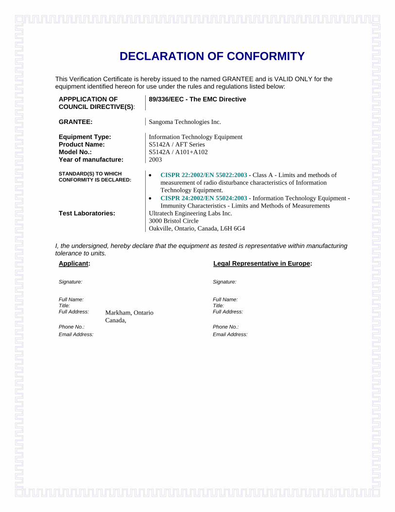
This Verification Certificate is hereby issued to the named GRANTEE and is VALID ONLY for the equipment identified hereon for use under the rules and regulations listed below:
APPPLICATION OF COUNCIL DIRECTIVE(S):
89/336/EEC - The EMC Directive
GRANTEE: Sangoma Technologies Inc. Equipment Type: Information Technology Equipment Product Name: S5142A / AFT Series Model No.: S5142A / A101+A102 Year of manufacture: 2003 STANDARD(S) TO WHICH CONFORMITY IS DECLARED:
• CISPR 22:2002/EN 55022:2003 - Class A - Limits and methods of measurement of radio disturbance characteristics of Information Technology Equipment.
• CISPR 24:2002/EN 55024:2003 - Information Technology Equipment - Immunity Characteristics - Limits and Methods of Measurements
Test Laboratories: Ultratech Engineering Labs Inc. 3000 Bristol Circle Oakville, Ontario, Canada, L6H 6G4
I, the undersigned, hereby declare that the equipment as tested is representative within manufacturing tolerance to units. Applicant: Legal Representative in Europe: Signature:
Signature:
Full Name: Full Name: Title: Title: Full Address: Markham, Ontario
Canada, Full Address:
Phone No.: Phone No.: Email Address: Email Address:
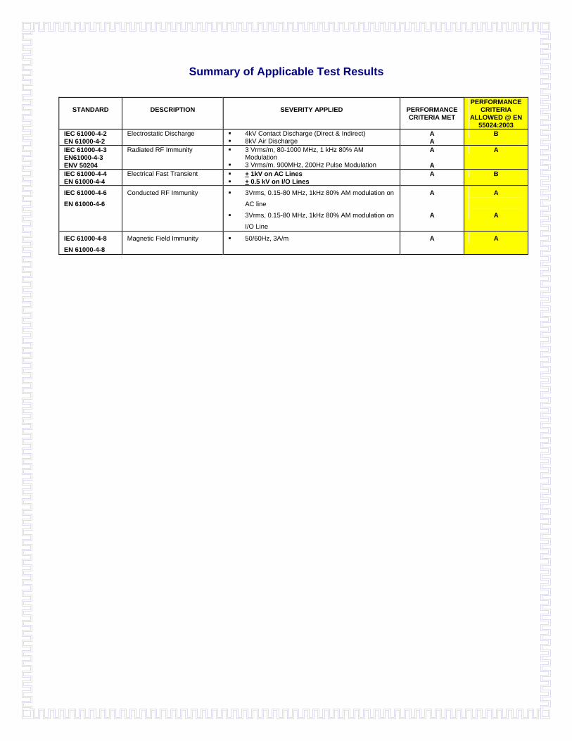
Summary of Applicable Test Results
STANDARD
DESCRIPTION
SEVERITY APPLIED
PERFORMANCE CRITERIA MET
PERFORMANCE CRITERIA
ALLOWED @ EN 55024:2003
IEC 61000-4-2 EN 61000-4-2
Electrostatic Discharge 4kV Contact Discharge (Direct & Indirect) 8kV Air Discharge
A A
B
IEC 61000-4-3 EN61000-4-3 ENV 50204
Radiated RF Immunity 3 Vrms/m, 80-1000 MHz, 1 kHz 80% AM Modulation
3 Vrms/m. 900MHz, 200Hz Pulse Modulation
A
A
A
IEC 61000-4-4 EN 61000-4-4
Electrical Fast Transient + 1kV on AC Lines + 0.5 kV on I/O Lines
A B
IEC 61000-4-6 EN 61000-4-6
Conducted RF Immunity 3Vrms, 0.15-80 MHz, 1kHz 80% AM modulation on
AC line
3Vrms, 0.15-80 MHz, 1kHz 80% AM modulation on
I/O Line
A
A
A
A
IEC 61000-4-8 EN 61000-4-8
Magnetic Field Immunity 50/60Hz, 3A/m A A
ENGINEERING TEST REPORT
S5142A / AFT Series Model No.: S5142A / A101+A102
Applicant: Sangoma Technologies Inc. 50 McIntosh Drive, Suite 120 Markham, Ontario Canada, L3R 9T3
In Accordance With
EUROPEAN STANDARD: CISPR 24:2002/EN 55024:2003 ELECTROMAGNETIC COMPATIBILITY REQUIREMENTS
Information Technology Equipment Immunity Characteristics - Limits and Methods of Measurements
UltraTech's File No.: SNG027-EN24
This Test report is Issued under the Authority of Tri M. Luu, Professional Engineer, Vice President of Engineering UltraTech Group of Labs
Date: May 17, 2006
Report Prepared by: Chau Le
Tested by: Quan & Pam, EMC Technicians
Issued Date: May 17, 2006
Test Dates: Dec. 18, 21, 2003 & Jan7, 2004
The results in this Test Report apply only to the sample(s) tested, and the sample tested is randomly selected. This report must not be used by the client to claim product endorsement by NVLAP or any agency of the US Government.
UltraTech
3000 Bristol Circle, Oakville, Ontario, Canada, L6H 6G4 Tel.: (905) 829-1570 Fax.: (905) 829-8050
Website: www.ultratech-labs.com Email: [email protected], Email: [email protected]
2
31040/SIT C-1376 46390-2049 200093-0 SL2-IN-E-1119R 00-034
CISPR 24:2002 / EN 55024:2003 - Electromagnetic Compatibility Page 2 S5142A / AFT Series Model No.: S5142A / A101+A102
ULTRATECH GROUP OF LABS File #: SNG027-EN24 3000 Bristol Circle, Oakville, Ontario, Canada L6H 6G4 May 17, 2006 Tel. #: 905-829-1570, Fax. #: 905-829-8050, Email: [email protected], Website: http://www.ultratech-labs.com
TABLE OF CONTENTS
EXHIBIT 1. INTRODUCTION .........................................................................................................................................4 1.1. SCOPE.........................................................................................................................................................................4 1.2. APPLICABILITY OVERVIEW TABLES..................................................................................................................5 1.3. NORMATIVE REFERENCES ...................................................................................................................................6
EXHIBIT 2. PERFORMANCE ASSESSMENT ..............................................................................................................7 2.1. CLIENT INFORMATION .............................................................................................................................................7 2.2. EQUIPMENT UNDER TEST (EUT) INFORMATION .............................................................................................................7 2.3. LIST OF COMPONENTS/PARTS OF THE EUT....................................................................................................................8 2.4. LIST OF EUT’S PORTS ..................................................................................................................................................8 2.5. ANCILLARY EQUIPMENT ...............................................................................................................................................9
EXHIBIT 3. EUT OPERATING CONDITIONS AND CONFIGURATIONS DURING TESTS .............................10 3.1. CLIMATE TEST CONDITIONS ........................................................................................................................................10 3.2. OPERATIONAL TEST CONDITIONS & ARRANGEMENT FOR TEST SIGNALS......................................................................10 3.3. BLOCK DIAGRAM OF TEST SETUP.....................................................................................................................11
EXHIBIT 4. SUMMARY OF TEST RESULTS .............................................................................................................12 4.1. LOCATION OF TESTS ............................................................................................................................................12 4.2. SUMMARY OF EMC IMMUNITY TEST RESULTS............................................................................................................12 4.3. MODIFICATIONS INCORPORATED IN THE EUT FOR COMPLIANCE PURPOSES ..................................................................12
EXHIBIT 5. MEASUREMENTS, EXAMINATIONS & TEST DATA FOR EMC IMMUNITY.............................13 5.1. TEST PROCEDURES .....................................................................................................................................................13 5.2. MEASUREMENT EQUIPMENT USED:..............................................................................................................................13 5.3. PERFORMANCE CRITERIA: .................................................................................................................................13 5.4. ELECTROSTATIC DISCHARGE @ CISPR 24:2002/EN 55024:2003 & EN 61000-4-2 .....................................................14
5.4.1. Limits @ CISPR 24:2002/EN 55024:2003........................................................................................................14 5.4.2. Method of Measurements...................................................................................................................................14 5.4.3. Test Equipment List ...........................................................................................................................................14 5.4.4. Test Data............................................................................................................................................................15 5.4.5. Photographs of Test Setup .................................................................................................................................18
5.5. R.F. ELECTROMAGNETIC FIELDS @ CISPR 24:2002/EN 55024:2003 & EN 61000-4-3 ...............................................19 5.5.1. Limits @ CISPR 24:2002/EN 55024:2003........................................................................................................19 5.5.2. Method of Measurements...................................................................................................................................19 5.5.3. Test Equipment List ...........................................................................................................................................19 5.5.4. Test Data............................................................................................................................................................20 5.5.5. Photographs of Test Setup .................................................................................................................................21
5.6. ELECTRICAL FAST TRANSIENT @ CISPR 24:2002/EN 55024:2003 & EN 61000-4-4 ..................................................22 5.6.1. Limits @ CISPR 24:2002/EN 55024:2003........................................................................................................22 5.6.2. Method of Measurements...................................................................................................................................22 5.6.3. Test Equipment List ...........................................................................................................................................22 5.6.4. Test Data............................................................................................................................................................23 5.6.5. Photographs of Test Setup .................................................................................................................................24
5.7. R.F. CONDUCTED IMMUNITY @ CISPR 24:2002/EN 55024:2003 & EN 61000-4-6 ...........................................25 5.7.1. Limits @ CISPR 24:2002/EN 55024:2003........................................................................................................25 5.7.2. Method of Measurements...................................................................................................................................25 5.7.3. Test Equipment List ...........................................................................................................................................25 5.7.4. Test Data............................................................................................................................................................26
CISPR 24:2002 / EN 55024:2003 - Electromagnetic Compatibility Page 3 S5142A / AFT Series Model No.: S5142A / A101+A102
ULTRATECH GROUP OF LABS File #: SNG027-EN24 3000 Bristol Circle, Oakville, Ontario, Canada L6H 6G4 May 17, 2006 Tel. #: 905-829-1570, Fax. #: 905-829-8050, Email: [email protected], Website: http://www.ultratech-labs.com
5.7.5. Photographs of Test Setup .................................................................................................................................27 5.8. POWER MAGNETIC FIELD IMMUNITY @ CISPR 24:2002/EN 55024:2003 & EN 61000-8 ............................................28
5.8.1. limits @ CISPR 24:2002/EN 55024:2003 .........................................................................................................28 5.8.2. Method of Measurements...................................................................................................................................28 5.8.3. Test Equipment List ...........................................................................................................................................28 5.8.4. Test Data............................................................................................................................................................28 5.8.5. Photographs of Test Setup .................................................................................................................................29
EXHIBIT 6. MEASUREMENT METHODS FOR EMC IMMUNITY MEASUREMENTS ....................................30 6.1. ELECTROSTATIC DISCHARGE REQUIREMENTS @ EN 61000-4-2 ................................................................................30
6.1.1. Introduction .......................................................................................................................................................30 6.1.2. Objective ............................................................................................................................................................30 6.1.3. Application of the Static Electricity Discharges ................................................................................................30 6.1.4. Direct Application of Discharges to EUT..........................................................................................................31 6.1.5. Indirect Application of Discharges to EUT .......................................................................................................31 6.1.6. Radiated Immunity Requirements @ EN 61000-4-3 .........................................................................................34 6.1.7. Introduction .......................................................................................................................................................34 6.1.8. Objective ............................................................................................................................................................34 6.1.9. Unit of Measurements........................................................................................................................................34 6.1.10. Locations of Test Site.........................................................................................................................................34 6.1.11. Test Procedures .................................................................................................................................................34
6.2. ELECTRICAL FAST TRANSIENT REQUIREMENTS @ EN 61000-4-4..............................................................................37 6.2.1. Introduction .......................................................................................................................................................37 6.2.2. Objective ............................................................................................................................................................37 6.2.3. Test Procedures .................................................................................................................................................37
6.3. CONDUCTED RF IMMUNITY @ EN 61000-4-6............................................................................................................39 6.3.1. Introduction .......................................................................................................................................................39 6.3.2. Objective ............................................................................................................................................................39 6.3.3. Test Setup and Application ................................................................................................................................39
6.4. POWER MAGNETIC FIELD IMMUNITY @ EN 61000-4-8...................................................................................44 6.4.1. Introduction .......................................................................................................................................................44 6.4.2. Objective ............................................................................................................................................................44 6.4.3. The severity levels to be met are as follows:......................................................................................................44
6.5. TEST APPLICATION AND SETUP ..................................................................................................................................44 6.5.1. TEST METHOD #1: Using a Helmholtz Coil....................................................................................................44 6.5.2. TEST METHOD #2: Using an Induction Coil, Ref. IEC 61000-4-8, Para. 6.2.1 .............................................45
EXHIBIT 7. LABELLING REQUIREMENTS..............................................................................................................46
CISPR 24:2002 / EN 55024:2003 - Electromagnetic Compatibility Page 4 S5142A / AFT Series Model No.: S5142A / A101+A102
ULTRATECH GROUP OF LABS File #: SNG027-EN24 3000 Bristol Circle, Oakville, Ontario, Canada L6H 6G4 May 17, 2006 Tel. #: 905-829-1570, Fax. #: 905-829-8050, Email: [email protected], Website: http://www.ultratech-labs.com
EXHIBIT 1. INTRODUCTION
1.1. SCOPE Reference: CISPR 24:2002/EN 55024:2003 Title Electromagnetic Compatibility Requirements, - Information Technology Equipment -
Immunity Characteristics - Limits and Methods of Measurements. Purpose of Test: To gain EC Declaration of Conformity Compliance in accordance with CISPR 24:2002/EN
55024:2003 Method of Measurements: The immunity tests were performed in accordance with CISPR 24:2002/EN 55024:2003, EN
61000-3-2, EN 61000-3-3 and EN 61000-4-2 through EN 61000-4-11. Environmental Classification:
Residential Light-industry, Commercial
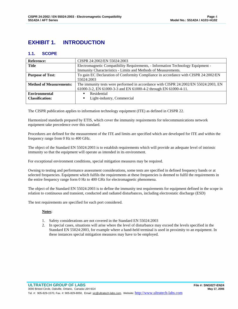
The CISPR publication applies to information technology equipment (ITE) as defined in CISPR 22. Harmonized standards prepared by ETIS, which cover the immunity requirements for telecommunications network equipment take precedence over this standard. Procedures are defined for the measurement of the ITE and limits are specified which are developed for ITE and within the frequency range from 0 Hz to 400 GHz. The object of the Standard EN 55024:2003 is to establish requirements which will provide an adequate level of intrinsic immunity so that the equipment will operate as intended in its environment. For exceptional environment conditions, special mitigation measures may be required. Owning to testing and performance assessment considerations, some tests are specified in defined frequency bands or at selected frequencies. Equipment which fulfils the requirements at these frequencies is deemed to fulfil the requirements in the entire frequency range form 0 Hz to 400 GHz for electromagnetic phenomena. The object of the Standard EN 55024:2003 is to define the immunity test requirements for equipment defined in the scope in relation to continuous and transient, conducted and radiated disturbances, including electrostatic discharge (ESD) The test requirements are specified for each port considered.
Notes:
1. Safety considerations are not covered in the Standard EN 55024:2003 2. In special cases, situations will arise where the level of disturbance may exceed the levels specified in the
Standard EN 55024:2003, for example where a hand-held terminal is used in proximity to an equipment. In these instances special mitigation measures may have to be employed.
CISPR 24:2002 / EN 55024:2003 - Electromagnetic Compatibility Page 5 S5142A / AFT Series Model No.: S5142A / A101+A102
ULTRATECH GROUP OF LABS File #: SNG027-EN24 3000 Bristol Circle, Oakville, Ontario, Canada L6H 6G4 May 17, 2006 Tel. #: 905-829-1570, Fax. #: 905-829-8050, Email: [email protected], Website: http://www.ultratech-labs.com
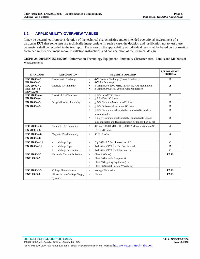
1.2. APPLICABILITY OVERVIEW TABLES It may be determined from consideration of the technical characteristics and/or intended operational environment of a particular EUT that some tests are technically inappropriate. In such a case, the decision and justification not to test these parameters shall be recorded in the test report. Decisions on the applicability of individual tests shall be based on information contained in user document and/or installation instructions, and consideration of the technical design. CISPR 24:2002/EN 55024:2003 - Information Technology Equipment - Immunity Characteristics - Limits and Methods of Measurements.
STANDARD
DESCRIPTION
SEVERITY APPLIED
PERFORMANCE CRITERIA
IEC 61000-4-2 EN 61000-4-2
Electrostatic Discharge 4kV Contact Discharge (Direct & Indirect) 8kV Air Discharge
B
IEC 61000-4-3 EN61000-4-3 ENV 50204
Radiated RF Immunity 3 Vrms/m, 80-1000 MHz, 1 kHz 80% AM Modulation 3 Vrms/m. 900MHz, 200Hz Pulse Modulation
A
IEC 61000-4-4 EN 61000-4-4
Electrical Fast Transient + 1kV on AC/DC Lines + 0.5 kV on I/O Lines
B
EN 61000-4-5 EN 61000-4-5
Surge Withstand Immunity + 2kV Common Mode on AC Lines + 1kV Differential mode on AC lines + 1kV Common mode ports that connected to outdoor
telecom cables + 0.5kV Common mode ports that connected to indoor
telecom cables and DC input supply (if longer than 10 m)
B B B
B
IEC 61000-4-6 EN 61000-4-6
Conducted RF Immunity 3Vrms, 0.15-80 MHz, 1kHz 80% AM modulation on AC, DC & I/O Lines
A
IEC 61000-4-8 EN 61000-4-8
Magnetic Field Immunity 50 Hz, 1 A/m A
IEC 61000-4-11 EN 61000-4-11
Voltage Dips Voltage Dips Voltage Interruption
Dip 30% - 0.5 Sec. Interval on AC Reduction >95% for 10m Sec. interval Reduction >95% for 5 Sec. interval
C B C
IEC 61000-3-2 EN61000-3-2
Harmonic Current Emissions Class A (Other) Class B (Portable Equipment) Class C (Lighting Equipment) or Class D (Special Current Waveform)
PASS
IEC 61000-3-3 EN61000-3-3
Voltage Fluctuation and Flicker in Low-Voltage Supply Systems
Voltage Fluctuation Flicker
PASS PASS
CISPR 24:2002 / EN 55024:2003 - Electromagnetic Compatibility Page 6 S5142A / AFT Series Model No.: S5142A / A101+A102
ULTRATECH GROUP OF LABS File #: SNG027-EN24 3000 Bristol Circle, Oakville, Ontario, Canada L6H 6G4 May 17, 2006 Tel. #: 905-829-1570, Fax. #: 905-829-8050, Email: [email protected], Website: http://www.ultratech-labs.com
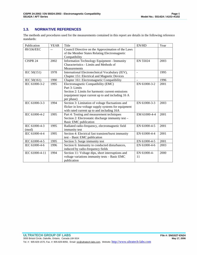
1.3. NORMATIVE REFERENCES The methods and procedures used for the measurements contained in this report are details in the following reference standards:
Publication YEAR Title EN/HD Year 89/336/EEC -- Council Directive on the Approximation of the Laws
of the Member States Relating Electromagnetic Compatibility
CISPR 24 2002 Information Technology Equipment - Immunity Characteristics - Limits and Methods of Measurements
EN 55024 2003
IEC 50(151) 1978 International Electrotechnical Vocabulary (IEV), Chapter 151: Electrical and Magnetic Devices
- 1995
IEC 50(161) 1990 Chapter 161: Electromagnetic Compatibility - 1996 IEC 61000-3-2 1995 Electromagnetic Compatibility (EMC)
Part 3: Limits Section 2: Limits for harmonic current emissions (equipment input current up to and including 16 A per phase)
EN 61000-3-2
2001
IEC 61000-3-3 1994 Section 3: Limitation of voltage fluctuations and flicker in low-voltage supply systems for equipment with rated current up to and including 16A
EN 61000-3-3 2003
IEC 61000-4-2 1995 Part 4: Testing and measurement techniques Section 2: Electrostatic discharge immunity test – Basic EMC publication
EM 61000-4-4 2001
IEC 61000-4-3 (mod)
1995 Radiated radio-frequency, electromagnetic field immunity test
EN 61000-4-5 2001
IEC 61000-4-4 1995 Section 4: Electrical fast transient/burst immunity test – Basic EMC publication
EN 61000-4-4 2001
IEC 61000-4-5 1995 Section 5: Surge immunity test EN 61000-4-5 2001 IEC 61000-4-6 1996 Section 6: Immunity to conducted disturbances,
induced by radio-frequency fields EN 61000-4-6 2003
IEC 61000-4-11 1994 Section 11: Voltage dips, short interruptions and voltage variations immunity tests – Basic EMC publication
EN 61000-4-11
2000
CISPR 24:2002 / EN 55024:2003 - Electromagnetic Compatibility Page 7 S5142A / AFT Series Model No.: S5142A / A101+A102
ULTRATECH GROUP OF LABS File #: SNG027-EN24 3000 Bristol Circle, Oakville, Ontario, Canada L6H 6G4 May 17, 2006 Tel. #: 905-829-1570, Fax. #: 905-829-8050, Email: [email protected], Website: http://www.ultratech-labs.com
EXHIBIT 2. PERFORMANCE ASSESSMENT
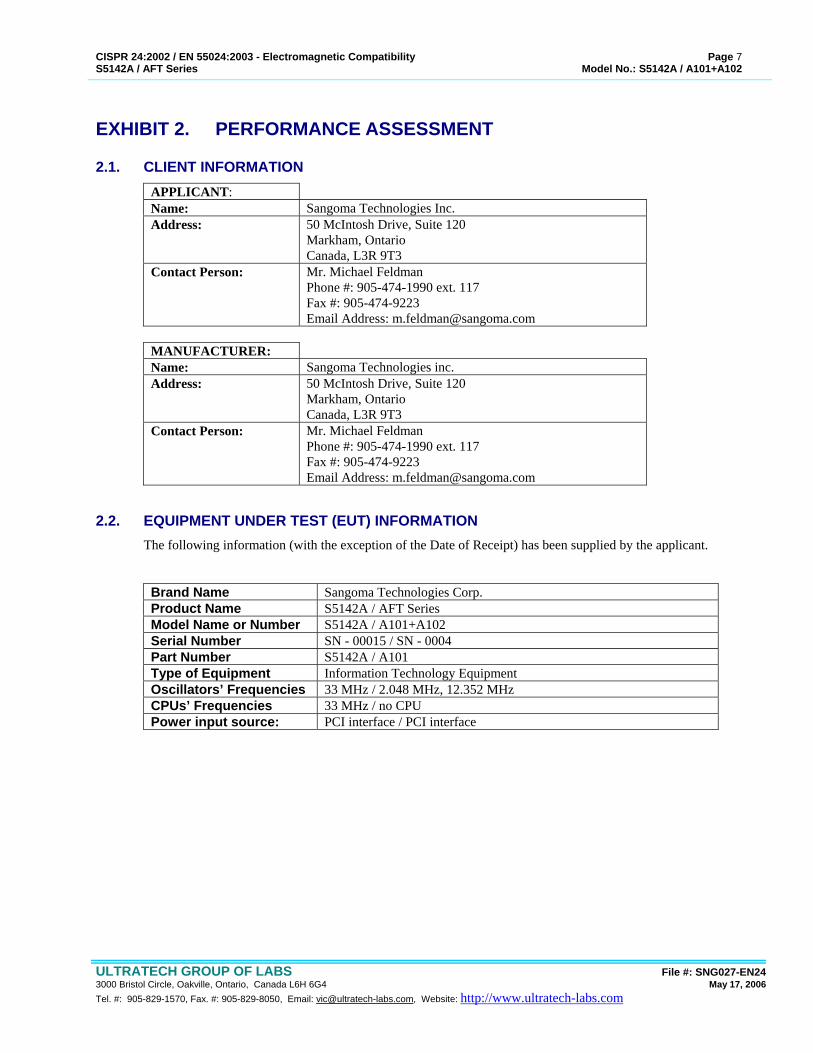
2.1. CLIENT INFORMATION APPLICANT: Name: Sangoma Technologies Inc. Address: 50 McIntosh Drive, Suite 120
Markham, Ontario Canada, L3R 9T3
Contact Person: Mr. Michael Feldman Phone #: 905-474-1990 ext. 117 Fax #: 905-474-9223 Email Address: [email protected]
MANUFACTURER: Name: Sangoma Technologies inc. Address: 50 McIntosh Drive, Suite 120
Markham, Ontario Canada, L3R 9T3
Contact Person: Mr. Michael Feldman Phone #: 905-474-1990 ext. 117 Fax #: 905-474-9223 Email Address: [email protected]
2.2. EQUIPMENT UNDER TEST (EUT) INFORMATION The following information (with the exception of the Date of Receipt) has been supplied by the applicant. Brand Name Sangoma Technologies Corp. Product Name S5142A / AFT Series Model Name or Number S5142A / A101+A102 Serial Number SN - 00015 / SN - 0004 Part Number S5142A / A101 Type of Equipment Information Technology Equipment Oscillators’ Frequencies 33 MHz / 2.048 MHz, 12.352 MHz CPUs’ Frequencies 33 MHz / no CPU Power input source: PCI interface / PCI interface

CISPR 24:2002 / EN 55024:2003 - Electromagnetic Compatibility Page 8 S5142A / AFT Series Model No.: S5142A / A101+A102
ULTRATECH GROUP OF LABS File #: SNG027-EN24 3000 Bristol Circle, Oakville, Ontario, Canada L6H 6G4 May 17, 2006 Tel. #: 905-829-1570, Fax. #: 905-829-8050, Email: [email protected], Website: http://www.ultratech-labs.com
2.3. LIST OF COMPONENTS/PARTS OF THE EUT Please refer to the part list provided by manufacturer.
2.4. LIST OF EUT’S PORTS Port
Number EUT’s Port Description Number of
Identical Ports
Connector Type
Cable Type (Shielded/Non-shielded)
1 For A101A 2 T1/E1 interface 2 ports RJ-48 Non-shielded 3 For S5142A 4 RS232/V35 1 port HDB78 Shielded
NOTES: (1) Ports of the EUT which in normal operation were connected to ancillary equipment through interconnecting
cables via a representative interconnecting cable to simulate the input/output characteristics. (2) Ports which are not connected to cables during normal intended operation (for factory/technical services uses
only): None

CISPR 24:2002 / EN 55024:2003 - Electromagnetic Compatibility Page 9 S5142A / AFT Series Model No.: S5142A / A101+A102
ULTRATECH GROUP OF LABS File #: SNG027-EN24 3000 Bristol Circle, Oakville, Ontario, Canada L6H 6G4 May 17, 2006 Tel. #: 905-829-1570, Fax. #: 905-829-8050, Email: [email protected], Website: http://www.ultratech-labs.com
2.5. ANCILLARY EQUIPMENT The EUT was tested while connected to the following representative configuration of ancillary equipment necessary to exercise the ports during tests: Ancillary Equipment # 1 Brand name: HP Pavilion 700
SYS: P9853A Serial Number: MX24818639 Cable Type: Shielded Connected to EUT’s Port: Card edge connector Ancillary Equipment # 2 Brand name: IBM Monitor Model Name or Number: 6547-OAN Serial Number: 23-CCV98 Cable Type: Shielded Connected to EUT’s Port: VGA port (HD15) Ancillary Equipment # 3 Brand name: Printer Hewlett Packard Model Name or Number: C4549A Serial Number: US6331G23P Cable Type: Shielded Connected to EUT’s Port: Parallel port (DB25) Ancillary Equipment # 4 Brand name: Compaq Mouse Part Number: 334684-006 Cable Type: Shielded Connected to EUT’s Port: Mouse port Ancillary Equipment # 5 Brand name: IBM Keyboard Model Name or Number: KB-9910 Serial Number: 0004884 Cable Type: Shielded Connected to EUT’s Port: Keyboard port Ancillary Equipment # 6 Brand name: Koss Speakers Cable Type: Non-shielded Connected to EUT’s Port: Phono
CISPR 24:2002 / EN 55024:2003 - Electromagnetic Compatibility Page 10 S5142A / AFT Series Model No.: S5142A / A101+A102
ULTRATECH GROUP OF LABS File #: SNG027-EN24 3000 Bristol Circle, Oakville, Ontario, Canada L6H 6G4 May 17, 2006 Tel. #: 905-829-1570, Fax. #: 905-829-8050, Email: [email protected], Website: http://www.ultratech-labs.com
EXHIBIT 3. EUT OPERATING CONDITIONS AND CONFIGURATIONS DURING TESTS
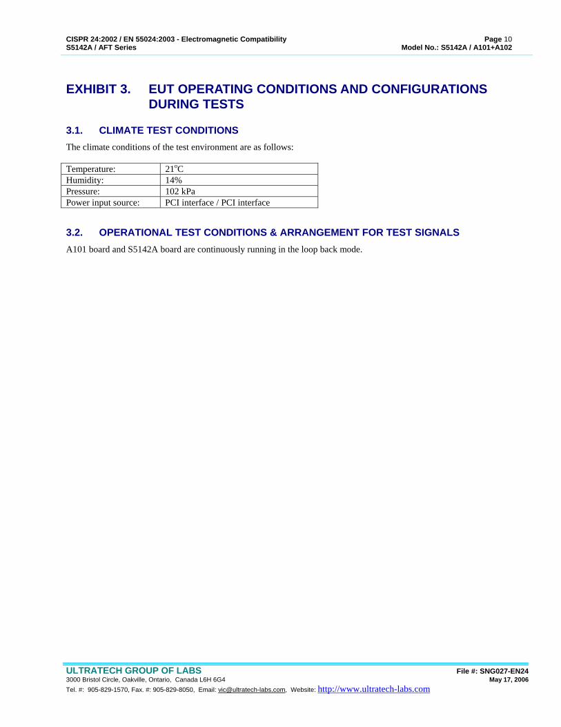
3.1. CLIMATE TEST CONDITIONS The climate conditions of the test environment are as follows: Temperature: 21oC Humidity: 14% Pressure: 102 kPa Power input source: PCI interface / PCI interface
3.2. OPERATIONAL TEST CONDITIONS & ARRANGEMENT FOR TEST SIGNALS A101 board and S5142A board are continuously running in the loop back mode.
CISPR 24:2002 / EN 55024:2003 - Electromagnetic Compatibility Page 11 S5142A / AFT Series Model No.: S5142A / A101+A102
ULTRATECH GROUP OF LABS File #: SNG027-EN24 3000 Bristol Circle, Oakville, Ontario, Canada L6H 6G4 May 17, 2006 Tel. #: 905-829-1570, Fax. #: 905-829-8050, Email: [email protected], Website: http://www.ultratech-labs.com
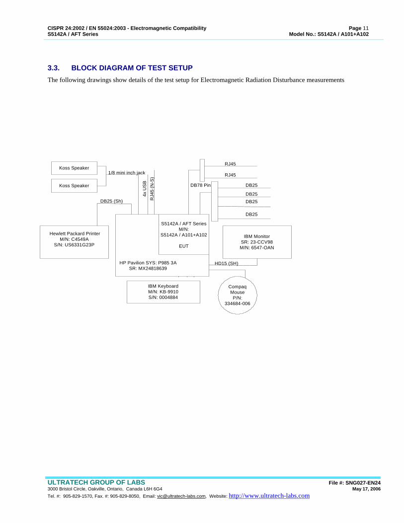
3.3. BLOCK DIAGRAM OF TEST SETUP The following drawings show details of the test setup for Electromagnetic Radiation Disturbance measurements
IBM MonitorSR: 23-CCV98M/N: 6547-OAN
IBM KeyboardM/N: KB-9910S/N: 0004884
Compaq MouseP/N:
334684-006
Hewlett Packard PrinterM/N: C4549A
S/N: US6331G23P
4x U
SB
RJ4
5 (N
-S)
RJ45
RJ45
DB25
DB25DB25
DB25
DB78 Pin
6 pin (Sh)
HD15 (SH)
S5142A / AFT SeriesM/N:
S5142A / A101+A102
EUT
HP Pavilion SYS: P985 3ASR: MX24818639
Koss Speaker
Koss Speaker
DB25 (Sh)
1/8 mini inch jack
CISPR 24:2002 / EN 55024:2003 - Electromagnetic Compatibility Page 12 S5142A / AFT Series Model No.: S5142A / A101+A102
ULTRATECH GROUP OF LABS File #: SNG027-EN24 3000 Bristol Circle, Oakville, Ontario, Canada L6H 6G4 May 17, 2006 Tel. #: 905-829-1570, Fax. #: 905-829-8050, Email: [email protected], Website: http://www.ultratech-labs.com
EXHIBIT 4. SUMMARY OF TEST RESULTS
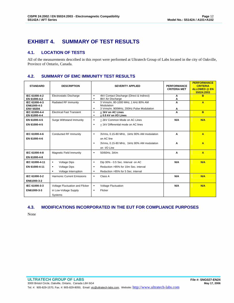
4.1. LOCATION OF TESTS All of the measurements described in this report were performed at Ultratech Group of Labs located in the city of Oakville, Province of Ontario, Canada.
4.2. SUMMARY OF EMC IMMUNITY TEST RESULTS
STANDARD
DESCRIPTION
SEVERITY APPLIED
PERFORMANCE CRITERIA MET
PERFORMANCE CRITERIA
ALLOWED @ EN 55024:2003
IEC 61000-4-2 EN 61000-4-2
Electrostatic Discharge 4kV Contact Discharge (Direct & Indirect) 8kV Air Discharge
A A
B
IEC 61000-4-3 EN61000-4-3 ENV 50204
Radiated RF Immunity 3 Vrms/m, 80-1000 MHz, 1 kHz 80% AM Modulation
3 Vrms/m. 900MHz, 200Hz Pulse Modulation
A
A
A
IEC 61000-4-4 EN 61000-4-4
Electrical Fast Transient + 1kV on AC Lines + 0.5 kV on I/O Lines
A B
EN 61000-4-5 EN 61000-4-5
Surge Withstand Immunity + 2kV Common Mode on AC Lines
+ 1kV Differential mode on AC lines
N/A N/A
IEC 61000-4-6 EN 61000-4-6
Conducted RF Immunity 3Vrms, 0.15-80 MHz, 1kHz 80% AM modulation
on AC line
3Vrms, 0.15-80 MHz, 1kHz 80% AM modulation
on I/O Line
A
A
A
A
IEC 61000-4-8 EN 61000-4-8
Magnetic Field Immunity 50/60Hz, 3A/m A A
IEC 61000-4-11 EN 61000-4-11
Voltage Dips
Voltage Dips
Voltage Interruption
Dip 30% - 0.5 Sec. Interval on AC
Reduction >95% for 10m Sec. interval
Reduction >95% for 5 Sec. interval
N/A N/A
IEC 61000-3-2 EN61000-3-2
Harmonic Current Emissions Class A N/A N/A
IEC 61000-3-3 EN61000-3-3
Voltage Fluctuation and Flicker
in Low-Voltage Supply
Systems
Voltage Fluctuation
Flicker
N/A N/A
4.3. MODIFICATIONS INCORPORATED IN THE EUT FOR COMPLIANCE PURPOSES None
CISPR 24:2002 / EN 55024:2003 - Electromagnetic Compatibility Page 13 S5142A / AFT Series Model No.: S5142A / A101+A102
ULTRATECH GROUP OF LABS File #: SNG027-EN24 3000 Bristol Circle, Oakville, Ontario, Canada L6H 6G4 May 17, 2006 Tel. #: 905-829-1570, Fax. #: 905-829-8050, Email: [email protected], Website: http://www.ultratech-labs.com
EXHIBIT 5. MEASUREMENTS, EXAMINATIONS & TEST DATA FOR EMC IMMUNITY
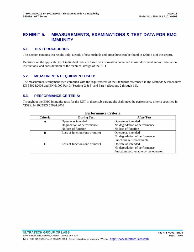
5.1. TEST PROCEDURES This section contains test results only. Details of test methods and procedures can be found in Exhibit 6 of this report. Decisions on the applicability of individual tests are based on information contained in user document and/or installation instructions, and consideration of the technical design of the EUT.
5.2. MEASUREMENT EQUIPMENT USED: The measurement equipment used complied with the requirements of the Standards referenced in the Methods & Procedures EN 55024:2003 and EN 61000 Part 3 (Sections 2 & 3) and Part 4 (Sections 2 through 11).
5.3. PERFORMANCE CRITERIA: Throughout the EMC immunity tests for the EUT in these sub-paragraphs shall meet the performance criteria specified in CISPR 24:2002/EN 55024:2003
Performance Criteria Criteria During Test After Test
A Operate as intended Degradation of performance No loss of function
Operate as intended No degradation of performance No loss of function
B Loss of function (one or more) Operate as intended No degradation of performance Functions self-recoverable
C Loss of function (one or more) Operate as intended No degradation of performance Functions recoverable by the operator
CISPR 24:2002 / EN 55024:2003 - Electromagnetic Compatibility Page 14 S5142A / AFT Series Model No.: S5142A / A101+A102
ULTRATECH GROUP OF LABS File #: SNG027-EN24 3000 Bristol Circle, Oakville, Ontario, Canada L6H 6G4 May 17, 2006 Tel. #: 905-829-1570, Fax. #: 905-829-8050, Email: [email protected], Website: http://www.ultratech-labs.com
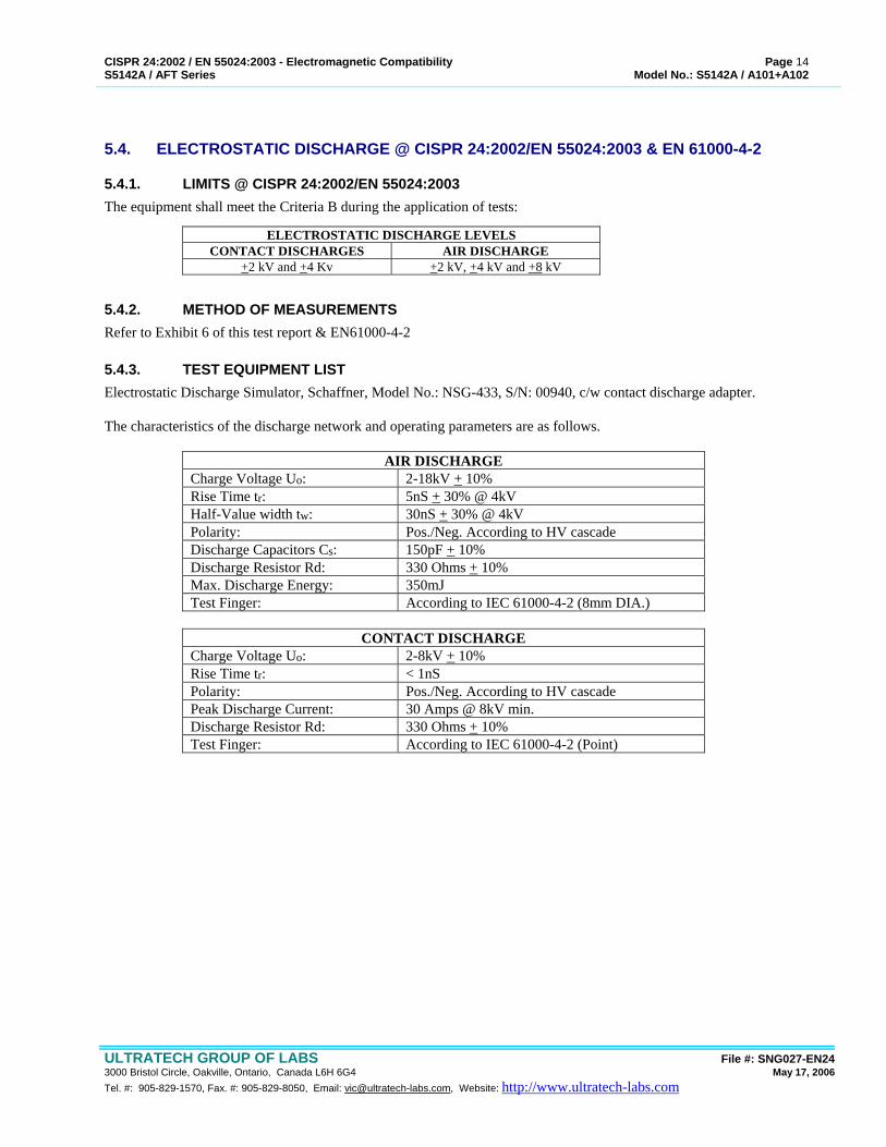
5.4. ELECTROSTATIC DISCHARGE @ CISPR 24:2002/EN 55024:2003 & EN 61000-4-2
5.4.1. LIMITS @ CISPR 24:2002/EN 55024:2003 The equipment shall meet the Criteria B during the application of tests:
ELECTROSTATIC DISCHARGE LEVELS CONTACT DISCHARGES AIR DISCHARGE
+2 kV and +4 Kv +2 kV, +4 kV and +8 kV
5.4.2. METHOD OF MEASUREMENTS Refer to Exhibit 6 of this test report & EN61000-4-2
5.4.3. TEST EQUIPMENT LIST Electrostatic Discharge Simulator, Schaffner, Model No.: NSG-433, S/N: 00940, c/w contact discharge adapter.
The characteristics of the discharge network and operating parameters are as follows.
AIR DISCHARGE Charge Voltage Uo: 2-18kV + 10% Rise Time tr: 5nS + 30% @ 4kV Half-Value width tw: 30nS + 30% @ 4kV Polarity: Pos./Neg. According to HV cascade Discharge Capacitors Cs: 150pF + 10% Discharge Resistor Rd: 330 Ohms + 10% Max. Discharge Energy: 350mJ Test Finger: According to IEC 61000-4-2 (8mm DIA.)
CONTACT DISCHARGE
Charge Voltage Uo: 2-8kV + 10% Rise Time tr: < 1nS Polarity: Pos./Neg. According to HV cascade Peak Discharge Current: 30 Amps @ 8kV min. Discharge Resistor Rd: 330 Ohms + 10% Test Finger: According to IEC 61000-4-2 (Point)

CISPR 24:2002 / EN 55024:2003 - Electromagnetic Compatibility Page 15 S5142A / AFT Series Model No.: S5142A / A101+A102
ULTRATECH GROUP OF LABS File #: SNG027-EN24 3000 Bristol Circle, Oakville, Ontario, Canada L6H 6G4 May 17, 2006 Tel. #: 905-829-1570, Fax. #: 905-829-8050, Email: [email protected], Website: http://www.ultratech-labs.com
5.4.4. TEST DATA
5.4.4.1. Indirect Contact Discharge to Horizontal Coupling Plane Located underneath the EUT.
APPLIED TO EUT’S
LOCATION
LEVEL (kV)
DISCHARGE COUNT
NOTE
OBSERVATION
Front +2 10 10 No performance degradation was observed -2 10 10 No performance degradation was observed +4 10 10 No performance degradation was observed -4 10 10 No performance degradation was observed Left Side +2 10 10 No performance degradation was observed -2 10 10 No performance degradation was observed +4 10 10 No performance degradation was observed -4 10 10 No performance degradation was observed Right Side +2 10 10 No performance degradation was observed -2 10 10 No performance degradation was observed +4 10 10 No performance degradation was observed -4 10 10 No performance degradation was observed REAR +2 10 10 No performance degradation was observed -2 10 10 No performance degradation was observed +4 10 10 No performance degradation was observed -4 10 10 No performance degradation was observed
CISPR 24:2002 / EN 55024:2003 - Electromagnetic Compatibility Page 16 S5142A / AFT Series Model No.: S5142A / A101+A102
ULTRATECH GROUP OF LABS File #: SNG027-EN24 3000 Bristol Circle, Oakville, Ontario, Canada L6H 6G4 May 17, 2006 Tel. #: 905-829-1570, Fax. #: 905-829-8050, Email: [email protected], Website: http://www.ultratech-labs.com
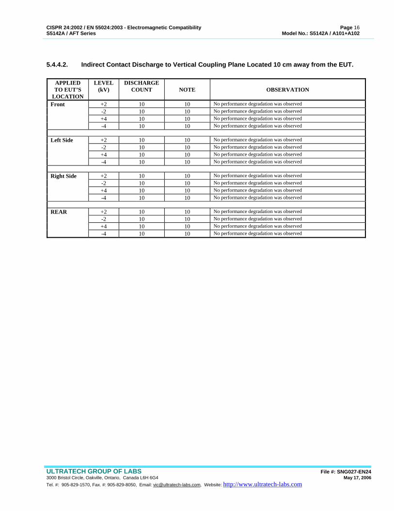
5.4.4.2. Indirect Contact Discharge to Vertical Coupling Plane Located 10 cm away from the EUT.
APPLIED TO EUT’S
LOCATION
LEVEL (kV)
DISCHARGE COUNT
NOTE
OBSERVATION
Front +2 10 10 No performance degradation was observed -2 10 10 No performance degradation was observed +4 10 10 No performance degradation was observed -4 10 10 No performance degradation was observed Left Side +2 10 10 No performance degradation was observed -2 10 10 No performance degradation was observed +4 10 10 No performance degradation was observed -4 10 10 No performance degradation was observed Right Side +2 10 10 No performance degradation was observed -2 10 10 No performance degradation was observed +4 10 10 No performance degradation was observed -4 10 10 No performance degradation was observed REAR +2 10 10 No performance degradation was observed -2 10 10 No performance degradation was observed +4 10 10 No performance degradation was observed -4 10 10 No performance degradation was observed
CISPR 24:2002 / EN 55024:2003 - Electromagnetic Compatibility Page 17 S5142A / AFT Series Model No.: S5142A / A101+A102
ULTRATECH GROUP OF LABS File #: SNG027-EN24 3000 Bristol Circle, Oakville, Ontario, Canada L6H 6G4 May 17, 2006 Tel. #: 905-829-1570, Fax. #: 905-829-8050, Email: [email protected], Website: http://www.ultratech-labs.com
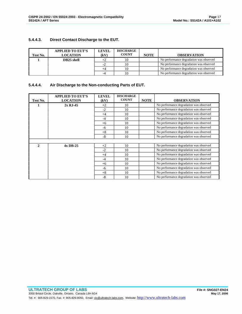
5.4.4.3. Direct Contact Discharge to the EUT.
Test No.
APPLIED TO EUT’S LOCATION
LEVEL (kV)
DISCHARGE COUNT
NOTE
OBSERVATION
1 DB25 shell +2 10 No performance degradation was observed -2 10 No performance degradation was observed +4 10 No performance degradation was observed -4 10 No performance degradation was observed
5.4.4.4. Air Discharge to the Non-conducting Parts of EUT.
Test No.
APPLIED TO EUT’S LOCATION
LEVEL (kV)
DISCHARGE COUNT
NOTE
OBSERVATION
1 2x RJ-45 +2 10 No performance degradation was observed -2 10 No performance degradation was observed +4 10 No performance degradation was observed -4 10 No performance degradation was observed +6 10 No performance degradation was observed -6 10 No performance degradation was observed +8 10 No performance degradation was observed -8 10 No performance degradation was observed
2 4x DB-25 +2 10 No performance degradation was observed -2 10 No performance degradation was observed +4 10 No performance degradation was observed -4 10 No performance degradation was observed +6 10 No performance degradation was observed -6 10 No performance degradation was observed +8 10 No performance degradation was observed -8 10 No performance degradation was observed
CISPR 24:2002 / EN 55024:2003 - Electromagnetic Compatibility Page 18 S5142A / AFT Series Model No.: S5142A / A101+A102
ULTRATECH GROUP OF LABS File #: SNG027-EN24 3000 Bristol Circle, Oakville, Ontario, Canada L6H 6G4 May 17, 2006 Tel. #: 905-829-1570, Fax. #: 905-829-8050, Email: [email protected], Website: http://www.ultratech-labs.com
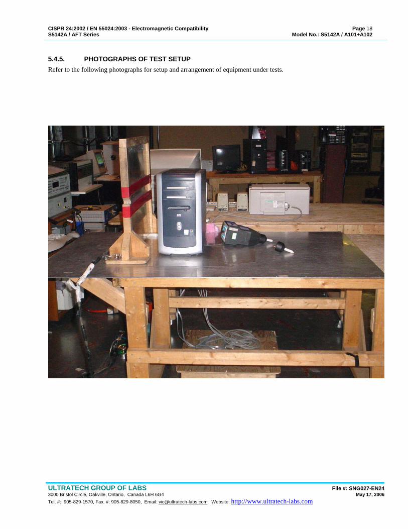
5.4.5. PHOTOGRAPHS OF TEST SETUP Refer to the following photographs for setup and arrangement of equipment under tests.
CISPR 24:2002 / EN 55024:2003 - Electromagnetic Compatibility Page 19 S5142A / AFT Series Model No.: S5142A / A101+A102
ULTRATECH GROUP OF LABS File #: SNG027-EN24 3000 Bristol Circle, Oakville, Ontario, Canada L6H 6G4 May 17, 2006 Tel. #: 905-829-1570, Fax. #: 905-829-8050, Email: [email protected], Website: http://www.ultratech-labs.com
5.5. R.F. ELECTROMAGNETIC FIELDS @ CISPR 24:2002/EN 55024:2003 & EN 61000-4-3
5.5.1. LIMITS @ CISPR 24:2002/EN 55024:2003 The equipment shall meet the Criteria A during the application of tests:
RADIO FREQUENCY ELECTROMAGNETIC FIELD Test Frequency RF Signal 80 to 1000 MHz 3 Vrms/m, 80%AM modulation
with 1 kHz Sine Wave Signal
5.5.2. METHOD OF MEASUREMENTS Refer to Exhibit 6 of this test report & EN61000-4-3
Setup - 3 Vrms/m Amplitude Modulated & Pulse Modulated Fields Method Used: Biconnilog antenna and full anechoic chamber Minimum Field Strength Exposure: 3 Vrms/m (measured un-modulated carrier) Frequency Range/Modulation 80-400 MHz, 80% AM modulation using 1 kHz sine modulating signal
400-1000 MHz, 80% AM modulation using 1 kHz sine modulating signal 900 + 5 MHz, 200 Hz Pulse Modulation
Antenna Polarization: Vertical & Horizontal Test Distance: 3m from faces of the EUT to geometric center of radiating antenna Frequency Steps: 200 kHz in 26 - 50MHz band
500 kHz in 50 - 100 MHz band 1 MHz in 100- 200 MHz band 2 MHz in 200 - 500 MHz band 5 MHz in 500 - 1000 MHz band
Dwell Time: 1000 mS minimum Sweep Rate: 1 x 10⁻³ decades/second minimum Exposures: Front, Back, Left, Right, Top, Bottom of the EUT
5.5.3. TEST EQUIPMENT LIST EQUIPMENT DESCRIPTION
1. Braden Fully Anechoic Chamber, 12'x24'x12' , Ferrite Tiles on all six surfaces (walls, ceiling and floor) 2. Emco 3143 Biconilog Antenna, S/N 1028, 26-1300 MHz, 1.3kW - 50Ω 3. Holiday Industries HI-3004 Field Strength Meter and Isotropic Probe, S/N 56562, 500kHz - 1.3GHz, 1 - 30V/m
ranges 4. Electrometrics EF4, Field strength Meter with 4 Isotropic Probes, S/N 106-1,2,3,4
10kHz - 1000MHz, 1-300V/m ranges 5. Boonton 92BD, RF Voltmeter, S/N 2406, 10kHz - 1000MHz 1mV-300V ranges 6. Eaton Advanced Electronics 3551B, RF Power Amplifier, S/N 189654, 50Watts, 100-520 MHz 7. Instruments for Industry IFI 404, RF Power Amplifier, S/N , 500Watts, 10kHz - 220MHz 8. ENI 5100L, RF Power Amplifier, S/N 1112-03046, 100Watts, 1-400MHz 9. Kalmus 720FC, RF Power Amplifier, S/N 062293-5, 40Watts, 400-1000 MHz 10. Amplifier Research AR 50A220, RF Power Amplifier, S/N 13362, 50Watts, 10kHz-220MHz 11. Fluke 6061A, RF Synthesized Signal Generator, S/N 4770301, 10kHz-1000MHz 12. Keithley 2000 Digital Multimeter, S/N 0592806, 6 1/2 digits with 10 channel scanner card & GPIB options 13. Trillium 486DX66 Personal Computer with GPIB card, S/N 930583 14. Ultratech EMC Control Software for Windows, Version EMC2000, Rev 1.0 15. Hewlett Packard 7450, 6 pen Plotter, S/N 2848A09939 16. Lightwave Communications FO-232, Fiber Optic RS-232 Modems, S/N 32961 17. HI-TRON MTC-4EO2, CCTV Camera monitoring system, S/N 20100413
CISPR 24:2002 / EN 55024:2003 - Electromagnetic Compatibility Page 20 S5142A / AFT Series Model No.: S5142A / A101+A102
ULTRATECH GROUP OF LABS File #: SNG027-EN24 3000 Bristol Circle, Oakville, Ontario, Canada L6H 6G4 May 17, 2006 Tel. #: 905-829-1570, Fax. #: 905-829-8050, Email: [email protected], Website: http://www.ultratech-labs.com
EQUIPMENT DESCRIPTION 18. Solar Electronic 7314-1016R, 2 x 10 MFD R.F. Capacitors
5.5.4. TEST DATA
EUT Face Exposed
Radiating Antenna
Polarization
Electric Fields @ 3 Vrms/m, 80-1000 MHz, 80% AM Mod with 1 kHz Sine
Wave Signal
Electric Field @ 3 Vrms/m, 900+5 MHz,
200 Hz Pulse Modulation
Front Horizontal No performance degradation was observed: No performance degradation was observed: Vertical No performance degradation was observed: No performance degradation was observed: Back Horizontal No performance degradation was observed: No performance degradation was observed: Vertical No performance degradation was observed: No performance degradation was observed: Left Side Horizontal No performance degradation was observed: No performance degradation was observed: Vertical No performance degradation was observed: No performance degradation was observed: Right Side Horizontal No performance degradation was observed: No performance degradation was observed: Vertical No performance degradation was observed: No performance degradation was observed: Top Horizontal No performance degradation was observed: No performance degradation was observed: Vertical No performance degradation was observed: No performance degradation was observed: Bottom Horizontal No performance degradation was observed: No performance degradation was observed: Vertical No performance degradation was observed: No performance degradation was observed:
CISPR 24:2002 / EN 55024:2003 - Electromagnetic Compatibility Page 21 S5142A / AFT Series Model No.: S5142A / A101+A102
ULTRATECH GROUP OF LABS File #: SNG027-EN24 3000 Bristol Circle, Oakville, Ontario, Canada L6H 6G4 May 17, 2006 Tel. #: 905-829-1570, Fax. #: 905-829-8050, Email: [email protected], Website: http://www.ultratech-labs.com
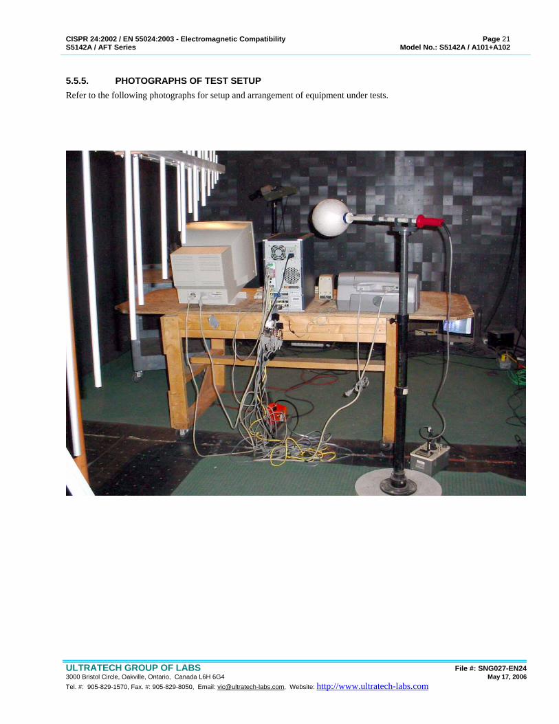
5.5.5. PHOTOGRAPHS OF TEST SETUP Refer to the following photographs for setup and arrangement of equipment under tests.

CISPR 24:2002 / EN 55024:2003 - Electromagnetic Compatibility Page 22 S5142A / AFT Series Model No.: S5142A / A101+A102
ULTRATECH GROUP OF LABS File #: SNG027-EN24 3000 Bristol Circle, Oakville, Ontario, Canada L6H 6G4 May 17, 2006 Tel. #: 905-829-1570, Fax. #: 905-829-8050, Email: [email protected], Website: http://www.ultratech-labs.com
5.6. ELECTRICAL FAST TRANSIENT @ CISPR 24:2002/EN 55024:2003 & EN 61000-4-4
5.6.1. LIMITS @ CISPR 24:2002/EN 55024:2003 The equipment shall meet the Criteria B during the application of tests:
FAST TRANSIENT COMMON MODE Port Tested Test Levels
AC Mains Input Ports • 0.5 kV Peak, Tr/Th = 5/50 nS, Rep Frequency: 5 kHz, Test duration = 1 minute
• 1.0 kV Peak, Tr/Th = 5/50 nS, Rep Frequency: 5 kHz, Test duration = 1 minute
DC, Signal, Control, Telecom I/O Ports (with cables longer than 3 m)
• 0.5 kV Peak, Tr/Th = 5/50 nS, Rep Frequency: 5 kHz, Test duration = 1 minute
5.6.2. METHOD OF MEASUREMENTS Refer to Exhibit 6 of this test report & EN61000-4-4
5.6.3. TEST EQUIPMENT LIST No. Equipment Descriptions Equipment Specifications 1 Microprocessor Controlled E-Class Series 400 ET/Burst
Test Generator, by KeyTek Instrument Corp., Model E420, Serial No.: 9205213: Open Circuit Output Voltage: Short Circuit Output Current: Waveshape of Surge Voltage and Current:
Generator Source Impedance: Polarity of the Surge: Internal or External Generator Trigger: Number of Tests:
Up to 4.4 kV (10kHz) and up to 8kV (2.5kHz) 0.25kA min, 2kA max. meet figure 2 and 3 of table 2 specified in IEC 61000-4-4 50
- Pulse Rise Time: 5nS + 30% - Pulse Duration: 50nS + 30% - Burst Train Repetition Rate: 1 kHz to 10 kHz - Burst Train Duration: 1 to 20mS - Burst Period: 0.3 to 5 seconds - Generator Source Impedance: 50 Ohms - Polarity of the Surge: positive/negative - Internal or External Generator Trigger: internal - Number of Tests: at least 5 positive and 5 negative at the selected
points. 50 Ohms Positive/negative Internal At least 5 positive and 5 negative at selected points.
2 Coupling Clamp, by KeyTek Instrument, Model CCL-
801/S, S/N: 9211339. Characteristics: typical coupling capacitance
between cable and clamp: Usable diameter range of round cables: Insulation withstanding capability: 5kV min (test
pulse 1.2/50uS)
50 pF to 200 pF 4mm to 40mm 5 kV minimum (test pulse: 1.2/50 µS)
3 IBM PS/1 Personal Computer with National Instruments GPIB Card and Keytek E-Class Software control. Fiber optic RS-232 link to ET Simulator.
CISPR 24:2002 / EN 55024:2003 - Electromagnetic Compatibility Page 23 S5142A / AFT Series Model No.: S5142A / A101+A102
ULTRATECH GROUP OF LABS File #: SNG027-EN24 3000 Bristol Circle, Oakville, Ontario, Canada L6H 6G4 May 17, 2006 Tel. #: 905-829-1570, Fax. #: 905-829-8050, Email: [email protected], Website: http://www.ultratech-labs.com
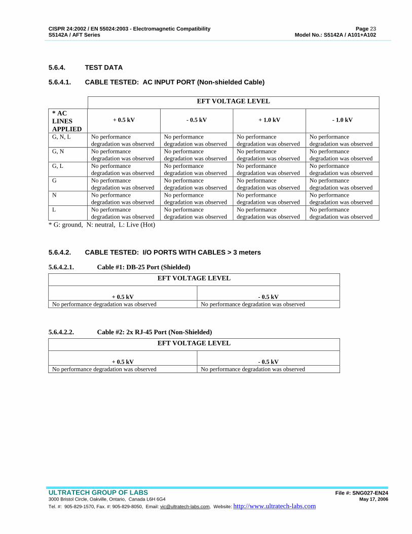
5.6.4. TEST DATA
5.6.4.1. CABLE TESTED: AC INPUT PORT (Non-shielded Cable)
EFT VOLTAGE LEVEL
* AC LINES APPLIED
+ 0.5 kV
- 0.5 kV
+ 1.0 kV
- 1.0 kV
G, N, L No performance degradation was observed
No performance degradation was observed
No performance degradation was observed
No performance degradation was observed
G, N No performance degradation was observed
No performance degradation was observed
No performance degradation was observed
No performance degradation was observed
G, L No performance degradation was observed
No performance degradation was observed
No performance degradation was observed
No performance degradation was observed
G No performance degradation was observed
No performance degradation was observed
No performance degradation was observed
No performance degradation was observed
N No performance degradation was observed
No performance degradation was observed
No performance degradation was observed
No performance degradation was observed
L No performance degradation was observed
No performance degradation was observed
No performance degradation was observed
No performance degradation was observed
* G: ground, N: neutral, L: Live (Hot)
5.6.4.2. CABLE TESTED: I/O PORTS WITH CABLES > 3 meters
5.6.4.2.1. Cable #1: DB-25 Port (Shielded) EFT VOLTAGE LEVEL
+ 0.5 kV
- 0.5 kV
No performance degradation was observed No performance degradation was observed
5.6.4.2.2. Cable #2: 2x RJ-45 Port (Non-Shielded) EFT VOLTAGE LEVEL
+ 0.5 kV
- 0.5 kV
No performance degradation was observed No performance degradation was observed
CISPR 24:2002 / EN 55024:2003 - Electromagnetic Compatibility Page 24 S5142A / AFT Series Model No.: S5142A / A101+A102
ULTRATECH GROUP OF LABS File #: SNG027-EN24 3000 Bristol Circle, Oakville, Ontario, Canada L6H 6G4 May 17, 2006 Tel. #: 905-829-1570, Fax. #: 905-829-8050, Email: [email protected], Website: http://www.ultratech-labs.com
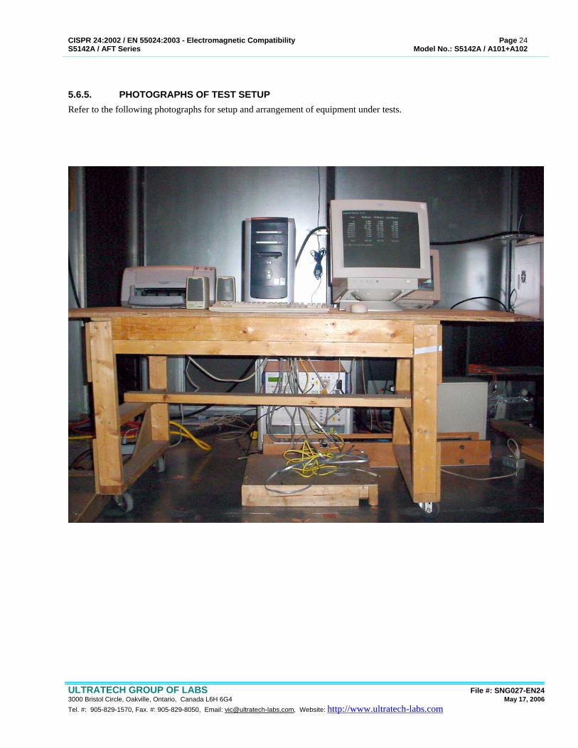
5.6.5. PHOTOGRAPHS OF TEST SETUP Refer to the following photographs for setup and arrangement of equipment under tests.
CISPR 24:2002 / EN 55024:2003 - Electromagnetic Compatibility Page 25 S5142A / AFT Series Model No.: S5142A / A101+A102
ULTRATECH GROUP OF LABS File #: SNG027-EN24 3000 Bristol Circle, Oakville, Ontario, Canada L6H 6G4 May 17, 2006 Tel. #: 905-829-1570, Fax. #: 905-829-8050, Email: [email protected], Website: http://www.ultratech-labs.com
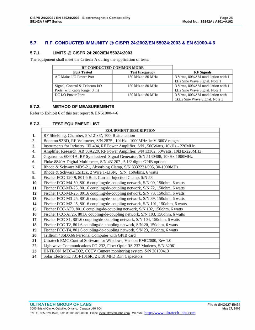
5.7. R.F. CONDUCTED IMMUNITY @ CISPR 24:2002/EN 55024:2003 & EN 61000-4-6
5.7.1. LIMITS @ CISPR 24:2002/EN 55024:2003 The equipment shall meet the Criteria A during the application of tests:
RF CONDUCTED COMMON MODE Port Tested Test Frequency RF Signals
AC Mains I/O Power Port 150 kHz to 80 MHz 3 Vrms, 80%AM modulation with 1 kHz Sine Wave Signal. Note 1
Signal, Control & Telecom I/O Ports (with cable longer 3 m)
150 kHz to 80 MHz 3 Vrms, 80%AM modulation with 1 kHz Sine Wave Signal. Note 1
DC I/O Power Ports 150 kHz to 80 MHz 3 Vrms, 80%AM modulation with 1kHz Sine Wave Signal. Note 1
5.7.2. METHOD OF MEASUREMENTS Refer to Exhibit 6 of this test report & EN61000-4-6
5.7.3. TEST EQUIPMENT LIST EQUIPMENT DESCRIPTION
1. RF Shielding, Chamber, 8’x12’x8’, 100dB attenuation 2. Boonton 92BD, RF Voltmeter, S/N 2875 , 10kHz - 1000MHz 1mV-300V ranges 3. Instruments for Industry IFI 404, RF Power Amplifier, S/N , 500Watts, 10kHz - 220MHz 4. Amplifier Research AR 50A220, RF Power Amplifier, S/N 13362, 50Watts, 10kHz-220MHz 5. Gigatronics 60601A, RF Synthesized Signal Generator, S/N 5130408, 10kHz-1000MHz 6. Fluke 8840A Digital Multimeter, S/N 431207 , 5 1/2 digits GPIB options 7. Rhode & Schwarz MDS-21, Absorbing Clamp, S/N 8332231/005, 30-1000MHz 8. Rhode & Schwarz ESH3Z, 2 Wire T-LISN, S/N, 150ohms, 6 watts 9. Fischer FCC-120-9, 801.6 Bulk Current Injection Clamp, S/N 53 10. Fischer FCC-M4-50, 801.6 coupling/de-coupling network, S/N 99, 150ohm, 6 watts 11. Fischer FCC-M3-25, 801.6 coupling/de-coupling network, S/N 72, 150ohm, 6 watts 12. Fischer FCC-M3-25, 801.6 coupling/de-coupling network, S/N 73, 150ohm, 6 watts 13. Fischer FCC-M3-25, 801.6 coupling/de-coupling network, S/N 39, 150ohm, 6 watts 14. Fischer FCC-M2-25, 801.6 coupling/de-coupling network, S/N 101, 150ohm, 6 watts 15. Fischer FCC-AF9, 801.6 coupling/de-coupling network, S/N 102, 150ohm, 6 watts 16. Fischer FCC-AF25, 801.6 coupling/de-coupling network, S/N 103, 150ohm, 6 watts 17. Fischer FCC-S1, 801.6 coupling/de-coupling network, S/N 104, 150ohm, 6 watts 18. Fischer FCC-T2, 801.6 coupling/de-coupling network, S/N 20, 150ohm, 6 watts 19. Fischer FCC-T4, 801.6 coupling/de-coupling network, S/N 23, 150ohm, 6 watts 20. Trillium 486DX66 Personal Computer with GPIB card 21. Ultratech EMC Control Software for Windows, Version EMC2000, Rev 1.0 22. Lightwave Communications FO-232, Fiber Optic RS-232 Modems, S/N 32961 23. HI-TRON MTC-4EO2, CCTV Camera monitoring system, S/N 20100413 24. Solar Electronic 7314-1016R, 2 x 10 MFD R.F. Capacitors
CISPR 24:2002 / EN 55024:2003 - Electromagnetic Compatibility Page 26 S5142A / AFT Series Model No.: S5142A / A101+A102
ULTRATECH GROUP OF LABS File #: SNG027-EN24 3000 Bristol Circle, Oakville, Ontario, Canada L6H 6G4 May 17, 2006 Tel. #: 905-829-1570, Fax. #: 905-829-8050, Email: [email protected], Website: http://www.ultratech-labs.com
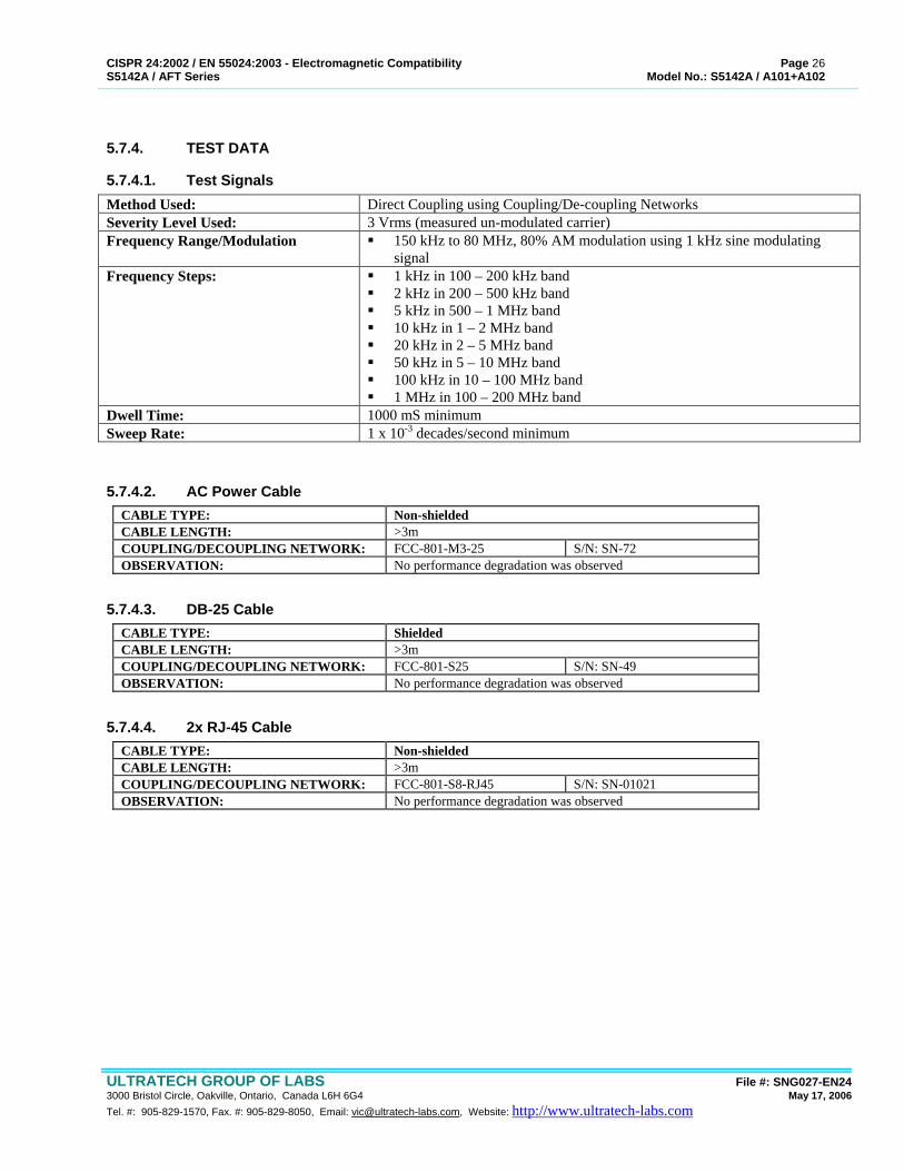
5.7.4. TEST DATA
5.7.4.1. Test Signals Method Used: Direct Coupling using Coupling/De-coupling Networks Severity Level Used: 3 Vrms (measured un-modulated carrier) Frequency Range/Modulation 150 kHz to 80 MHz, 80% AM modulation using 1 kHz sine modulating
signal Frequency Steps: 1 kHz in 100 – 200 kHz band
2 kHz in 200 – 500 kHz band 5 kHz in 500 – 1 MHz band 10 kHz in 1 – 2 MHz band 20 kHz in 2 – 5 MHz band 50 kHz in 5 – 10 MHz band 100 kHz in 10 – 100 MHz band 1 MHz in 100 – 200 MHz band
Dwell Time: 1000 mS minimum Sweep Rate: 1 x 10⁻³ decades/second minimum
5.7.4.2. AC Power Cable CABLE TYPE: Non-shielded CABLE LENGTH: >3m COUPLING/DECOUPLING NETWORK: FCC-801-M3-25 S/N: SN-72 OBSERVATION: No performance degradation was observed
5.7.4.3. DB-25 Cable CABLE TYPE: Shielded CABLE LENGTH: >3m COUPLING/DECOUPLING NETWORK: FCC-801-S25 S/N: SN-49 OBSERVATION: No performance degradation was observed
5.7.4.4. 2x RJ-45 Cable CABLE TYPE: Non-shielded CABLE LENGTH: >3m COUPLING/DECOUPLING NETWORK: FCC-801-S8-RJ45 S/N: SN-01021 OBSERVATION: No performance degradation was observed
CISPR 24:2002 / EN 55024:2003 - Electromagnetic Compatibility Page 27 S5142A / AFT Series Model No.: S5142A / A101+A102
ULTRATECH GROUP OF LABS File #: SNG027-EN24 3000 Bristol Circle, Oakville, Ontario, Canada L6H 6G4 May 17, 2006 Tel. #: 905-829-1570, Fax. #: 905-829-8050, Email: [email protected], Website: http://www.ultratech-labs.com
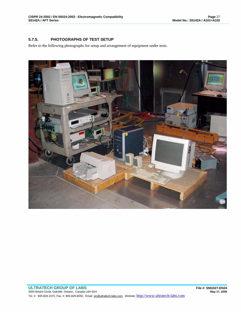
5.7.5. PHOTOGRAPHS OF TEST SETUP Refer to the following photographs for setup and arrangement of equipment under tests.
CISPR 24:2002 / EN 55024:2003 - Electromagnetic Compatibility Page 28 S5142A / AFT Series Model No.: S5142A / A101+A102
ULTRATECH GROUP OF LABS File #: SNG027-EN24 3000 Bristol Circle, Oakville, Ontario, Canada L6H 6G4 May 17, 2006 Tel. #: 905-829-1570, Fax. #: 905-829-8050, Email: [email protected], Website: http://www.ultratech-labs.com
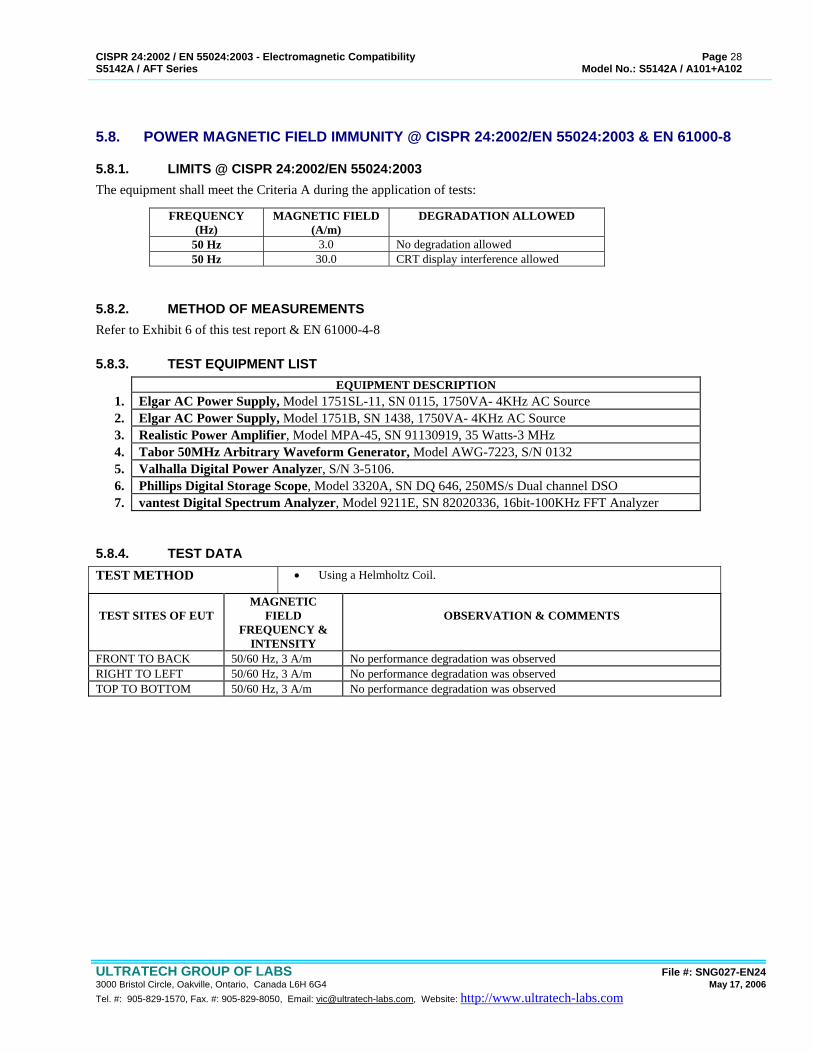
5.8. POWER MAGNETIC FIELD IMMUNITY @ CISPR 24:2002/EN 55024:2003 & EN 61000-8
5.8.1. LIMITS @ CISPR 24:2002/EN 55024:2003 The equipment shall meet the Criteria A during the application of tests:
FREQUENCY (Hz)
MAGNETIC FIELD (A/m)
DEGRADATION ALLOWED
50 Hz 3.0 No degradation allowed 50 Hz 30.0 CRT display interference allowed
5.8.2. METHOD OF MEASUREMENTS Refer to Exhibit 6 of this test report & EN 61000-4-8
5.8.3. TEST EQUIPMENT LIST EQUIPMENT DESCRIPTION
1. Elgar AC Power Supply, Model 1751SL-11, SN 0115, 1750VA- 4KHz AC Source 2. Elgar AC Power Supply, Model 1751B, SN 1438, 1750VA- 4KHz AC Source 3. Realistic Power Amplifier, Model MPA-45, SN 91130919, 35 Watts-3 MHz 4. Tabor 50MHz Arbitrary Waveform Generator, Model AWG-7223, S/N 0132 5. Valhalla Digital Power Analyzer, S/N 3-5106. 6. Phillips Digital Storage Scope, Model 3320A, SN DQ 646, 250MS/s Dual channel DSO 7. vantest Digital Spectrum Analyzer, Model 9211E, SN 82020336, 16bit-100KHz FFT Analyzer
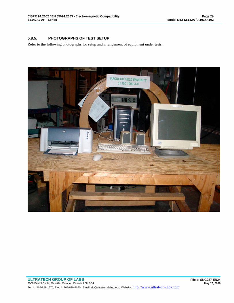
5.8.4. TEST DATA TEST METHOD • Using a Helmholtz Coil.
TEST SITES OF EUT
MAGNETIC FIELD
FREQUENCY & INTENSITY
OBSERVATION & COMMENTS
FRONT TO BACK 50/60 Hz, 3 A/m No performance degradation was observed RIGHT TO LEFT 50/60 Hz, 3 A/m No performance degradation was observed TOP TO BOTTOM 50/60 Hz, 3 A/m No performance degradation was observed
CISPR 24:2002 / EN 55024:2003 - Electromagnetic Compatibility Page 29 S5142A / AFT Series Model No.: S5142A / A101+A102
ULTRATECH GROUP OF LABS File #: SNG027-EN24 3000 Bristol Circle, Oakville, Ontario, Canada L6H 6G4 May 17, 2006 Tel. #: 905-829-1570, Fax. #: 905-829-8050, Email: [email protected], Website: http://www.ultratech-labs.com
5.8.5. PHOTOGRAPHS OF TEST SETUP Refer to the following photographs for setup and arrangement of equipment under tests.
CISPR 24:2002 / EN 55024:2003 - Electromagnetic Compatibility Page 30 S5142A / AFT Series Model No.: S5142A / A101+A102
ULTRATECH GROUP OF LABS File #: SNG027-EN24 3000 Bristol Circle, Oakville, Ontario, Canada L6H 6G4 May 17, 2006 Tel. #: 905-829-1570, Fax. #: 905-829-8050, Email: [email protected], Website: http://www.ultratech-labs.com
EXHIBIT 6. MEASUREMENT METHODS FOR EMC IMMUNITY MEASUREMENTS
6.1. ELECTROSTATIC DISCHARGE REQUIREMENTS @ EN 61000-4-2
6.1.1. INTRODUCTION These tests were conducted on a sample of the equipment for the purpose of Verification compliance with EN 61000-4-2 - Electromagnetic Compatibility Requirements, Part 2: Electrostatic Discharge Requirements. The problem of protecting equipment against the discharge of static electricity has gained considerable importance for manufacturers and users. The extensive use of microelectronics components has emphasized the need to define the aspects of the problem and to seek a solution in order to enhance product/system reliability. The problem of static electricity accumulation and subsequent discharges becomes more relevant for uncontrolled environments and the widespread application of equipment and systems in a wide range of industrial plants. Equipment may also be subjected to electromagnetic energies whenever discharges occur from personnel to nearby object. Additionally, discharges can occur between metal objects, such as chairs and tables, in the proximity of equipment. The effect of operator discharge may be a simple malfunction of the equipment or damage of electronic components. The dominant effects can be attributed to the parameters of the discharge current (rise time, duration, etc..) The generation of electrostatic charges is especially favored by the combination of synthetic fabrics and dry atmosphere. There are many possible variations in the charging process. A common situation is one in which an operator walks over a carpet and at each step loses or gains electrons from his body to the fabric. Friction between the operator’s clothing and his chair can also produce an exchange of charges. The operator’s body may be charged either directly or by electrostatic induction’s; in the latter case, a conducting carpet will give no protection unless the operator is adequately earthened to it. Electrostatic potentials exceeding 15,000 volts are not uncommon in carpeted office environments where humidity levels are relatively low. Too the human body, air discharges become noticeable at about 4,000 volts. At about 8,000 volts, air discharges start becoming uncomfortable and the discharge is just audible. At 15,000 volts, air discharges are downright unpleasant and the spark arcs across 1 cm air gaps with a bluish tint accompanied by a loud crack. At these levels, direct air discharges to printed circuit boards can cause permanent damage to programmable and memory logic.
6.1.2. OBJECTIVE The objective of this test is to determine the degradation of the performance of the EQUIPMENT UNDER TEST (EUT) when subjected to electrostatic discharges; the electrostatic discharges may occur from the personnel to the objects near the EUT (indirect discharge) or directly to EUT (direct discharge).
6.1.3. APPLICATION OF THE STATIC ELECTRICITY DISCHARGES Applicable discharge locations (HCP, VCP, points, surfaces etc ...), discharge methods (contact or air), voltage level, polarity, number of discharges, results and etc... were recorded in the TEST DATA.
CISPR 24:2002 / EN 55024:2003 - Electromagnetic Compatibility Page 31 S5142A / AFT Series Model No.: S5142A / A101+A102
ULTRATECH GROUP OF LABS File #: SNG027-EN24 3000 Bristol Circle, Oakville, Ontario, Canada L6H 6G4 May 17, 2006 Tel. #: 905-829-1570, Fax. #: 905-829-8050, Email: [email protected], Website: http://www.ultratech-labs.com
6.1.4. DIRECT APPLICATION OF DISCHARGES TO EUT Direct contact discharge was applied to all conductive points. Where contact discharge could not be obtained on insulated surfaces, air discharge was applied. Wherever applicable, The direct application of discharges to EUT was performed as follows:
• User accessible points and surfaces of EUT during normal operation. • Points accessible for maintenance purposes (not allowed unless agreed by the manufacturer and user). • The test was performed with single discharges on pre-selected points. The time interval between successive single
discharges (at least 10 discharges) was at least 1 second. Longer intervals might be necessary to determine whether a system failure had occurred. Note: The points to which the discharges were applied, and test voltage polarity to be used might be selected by means of an exploration carried out at a repetition rate of 20 discharges per second, or more.
• ESD generator was held perpendicular to the surface to which the discharge was applied, this improved the repeatability
of test results. • The discharge return cable of the generator was always kept at a distance of at least 0.2m from the EUT whilst the
discharged was being applied. • In the case of contact discharges, the tip of the discharge electrode touched the EUT, before the discharge switch was
operated. • If the coating was not declared as insulating coating by the equipment manufacturer, then the pointed tip of the generator
was used to penetrate the coating so as to make contact with the conducting substrate. • In the case of air discharges, the round discharge tip of the discharge electrode was approached as fast as possible
(without causing mechanical damage) to touch the EUT. After each discharge, the ESD generator (discharge electrode) was removed from the EUT. This procedure was repeated until the discharges were completed. In the case of the air discharge test, the contact relay, which was used for contact discharge, was removed.
6.1.5. INDIRECT APPLICATION OF DISCHARGES TO EUT Discharges to objects placed or installed near to the EUT were simulated by applying the discharges of the ESD generator to a coupling plane, in the contact discharge mode. • Horizontal Coupling Plane (HCP) under the EUT: At least 10 single discharges (in the most sensitive polarity) were
applied to the HCP, at points on each side of the EUT (front, rear, left and right sides). The ESD generator was positioned vertically at a distance of 0.1 m from the EUT, with the discharge electrode touching the coupling plane.
• Vertical Coupling Plane (VCP) under the EUT: At least 10 single discharges (in the most sensitive polarity) were
applied to the center of one vertical edge of the VCP. The VCP, of dimensions 0.5m x 0.5m, was placed parallel to, and positioned at a distance of 0.1 m from the EUT. Discharges were applied to the VCP, with this plane in sufficient different positions that the four faces of the EUT are completely illuminated.
CISPR 24:2002 / EN 55024:2003 - Electromagnetic Compatibility Page 32 S5142A / AFT Series Model No.: S5142A / A101+A102
ULTRATECH GROUP OF LABS File #: SNG027-EN24 3000 Bristol Circle, Oakville, Ontario, Canada L6H 6G4 May 17, 2006 Tel. #: 905-829-1570, Fax. #: 905-829-8050, Email: [email protected], Website: http://www.ultratech-labs.com
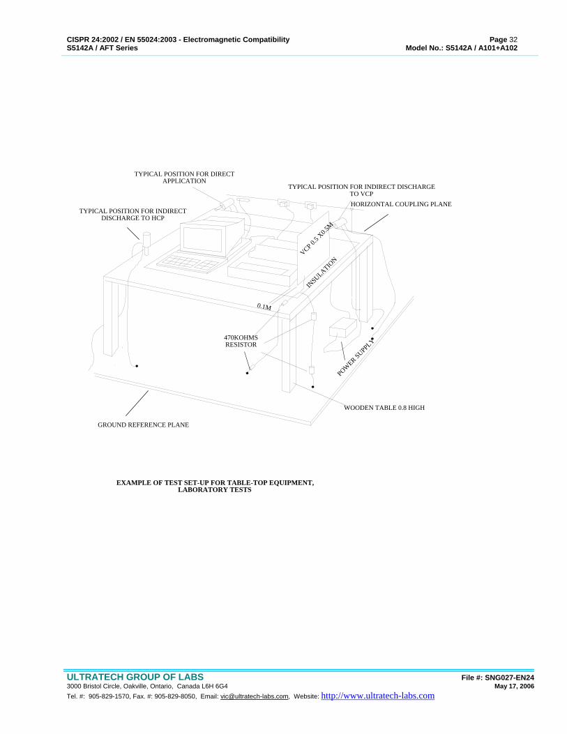
INSULATIO
N
VCP 0.5 X
0.5M
470KOHMSRESISTOR
POWER SUPPLY
HORIZONTAL COUPLING PLANE
TYPICAL POSITION FOR INDIRECT DISCHARGETO VCP
TYPICAL POSITION FOR DIRECTAPPLICATION
TYPICAL POSITION FOR INDIRECTDISCHARGE TO HCP
0.1M
GROUND REFERENCE PLANE
WOODEN TABLE 0.8 HIGH
EXAMPLE OF TEST SET-UP FOR TABLE-TOP EQUIPMENT,LABORATORY TESTS
CISPR 24:2002 / EN 55024:2003 - Electromagnetic Compatibility Page 33 S5142A / AFT Series Model No.: S5142A / A101+A102
ULTRATECH GROUP OF LABS File #: SNG027-EN24 3000 Bristol Circle, Oakville, Ontario, Canada L6H 6G4 May 17, 2006 Tel. #: 905-829-1570, Fax. #: 905-829-8050, Email: [email protected], Website: http://www.ultratech-labs.com
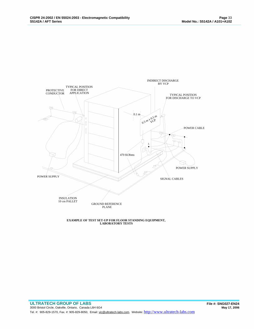
0.1 m
POWER CABLE
SIGNAL CABLES
POWER SUPPLY
470 KOhms
0.5 m x 0.5 m
VCP
POWER SUPPLY
TYPICAL POSITIONFOR DISCHARGE TO VCP
INDIRECT DISCHARGE BY VCP
TYPICAL POSITIONFOR DIRECT
APPLICATION
INSULATION10 cm PALLET
GROUND REFERENCE PLANE
PROTECTIVECONDUCTOR
EXAMPLE OF TEST SET-UP FOR FLOOR STANDING EQUIPMENT, LABORATORY TESTS

CISPR 24:2002 / EN 55024:2003 - Electromagnetic Compatibility Page 34 S5142A / AFT Series Model No.: S5142A / A101+A102
ULTRATECH GROUP OF LABS File #: SNG027-EN24 3000 Bristol Circle, Oakville, Ontario, Canada L6H 6G4 May 17, 2006 Tel. #: 905-829-1570, Fax. #: 905-829-8050, Email: [email protected], Website: http://www.ultratech-labs.com
6.1.6. RADIATED IMMUNITY REQUIREMENTS @ EN 61000-4-3
6.1.7. INTRODUCTION These tests were conducted on a sample of the equipment for the purpose of Verifying compliance with EN 61000-4-3 - Electromagnetic Compatibility for Industrial-Process Measurement and Control Equipment, Part 3: Immunity to radio-frequency radiated electromagnetic fields. Most electronic equipment is in some manner affected by electromagnetic radiation. This radiation is frequently generated by such sources as the small hand-held radio transceivers that are used by operating, maintenance, and security personnel, fixed station radio, television transmitters, vehicle radio transmitters, and various industrial electromagnetic sources. In addition to electromagnetic energy deliberately generated, there is spurious radiation caused by devices such as welders, thyristors, fluorescent lights, switches operating inductive loads, etc. For the most part, this interference manifests itself as conducted electrical interference and, as such, is dealt with in other parts of the standard. Methods employed to prevent effects from electromagnetic fields will normally also reduce the effects from these sources. The electromagnetic environment is determined by the strength of the electromagnetic field (field strength in volts per meter). The field strength is not easily measured without sophisticated instrumentation nor is it easily calculated by classical equations and formulae because of the effect of surrounding structures or the proximity of other equipment that will distort and/or reflect the electromagnetic waves.
6.1.8. OBJECTIVE The objective of this test is to determine the degradation of the performance of the EQUIPMENT UNDER TEST (EUT) when subjected to radio-frequency radiated electromagnetic fields at levels which are typical of commercial environments.
6.1.9. UNIT OF MEASUREMENTS Measurements of radiated field strengths are reported in units of volts per meter [V/m] at the distance specified in the report, where it is applicable.
6.1.10. LOCATIONS OF TEST SITE The Radiated Immunity Tests were performed in UltraTech's anechoic chamber, 24’(L) by 12'(W) by 12'(H).
6.1.11. TEST PROCEDURES The radiated immunity measurements were conducted in accordance with IEC 61000-4-3, Electromagnetic Compatibility Requirements - Generic Immunity Standard - Part 3: Immunity to Radiated Fields. The radiating antenna method is used for exposing the EUT to radiated electromagnetic waves. The tests are carried out in a fully shielded anechoic 12’x24’x12’ chamber to contain the high fields generated so as not to interfere with local communications. A uniform field of 0 to+6dB (1 to 2 times the required field strength) covering 1.5x1.5 meters square is established using an un-modulated carrier within the anechoic chamber using a 16 point field calibration as per the requirements of the standard. The calibration is performed on an un-modulated carrier using an isotropic field strength meter and probe. The probe is placed at a height of 1.5 meter from the floor of the chamber , at a distance of 3 meters from the geometric center of the biconi-log antenna. The frequency is swept over the amplifier range and the signal generator level at each frequency step is adjusted to maintain a field of 1.5 times the required field strength at that point to within a 0 to +10% tolerance. (Since the field is allowed to vary between 1 to 2 times within the test area, setting the center point of the area to 1.5 times the required field will ensure an average field within the required 0 to +6dB tolerance requirements). The adjusted level at each frequency is recorded in a calibration file and the process is repeated for each antenna polarization, each amplifier range and for each field strength calibration level. After the single point leveled calibration is performed, measurements of the field strength using the calibration file at sixteen 50cm equidistant points within the square test area is performed and 12 out of 16
CISPR 24:2002 / EN 55024:2003 - Electromagnetic Compatibility Page 35 S5142A / AFT Series Model No.: S5142A / A101+A102
ULTRATECH GROUP OF LABS File #: SNG027-EN24 3000 Bristol Circle, Oakville, Ontario, Canada L6H 6G4 May 17, 2006 Tel. #: 905-829-1570, Fax. #: 905-829-8050, Email: [email protected], Website: http://www.ultratech-labs.com
points (75% of the area) at each frequency step must fall within the uniformity criteria before the chamber is deemed to meet the uniformity criteria required by the standard. Prior to each test, a verification sweep using the appropriate calibration file is performed on the empty test volume to ensure that the field is within specification. For floor mounted equipment, the field strength is also measured at a 40 cm height and reported in the test result section of the report. A maximum step size of 1% of the fundamental is used in accordance with the standard and the calibration data entered into a file and a dwell time of at least 1 second is used to maintain a sweep rate of no greater than 1.5x10⁻³ decades/S. If it is determined that the EUT cannot respond within a one second time frame, the dwell time is increased appropriately. The geometric center of the radiating antenna is positioned 3 meters away from the EUT and both polarization's of the antenna is used. All six faces (four sides, top and bottom) of the EUT are then selected for direct exposure to the electromagnetic fields unless the EUT is large whereby the four sides are selected. The EUT is configured with all ports connected to support/ancillary or simulation equipment with cable lengths to provide for at least 1 meter exposure in the field. During the application of the EM field, the field strength in the vicinity of the EUT is monitored to determine what the actual field strength the EUT is being subjected to since distortion of the calibrated field is expected once the EUT is installed within the test volume. Should a failure occur, the field strength at that frequency can be manually set to determine the immunity threshold of the device under test. The performance of the EUT is monitored for any degradation during the application of the field using closed circuit monitors, fiber-optic coupled RS-232 serial interfaces or waveform monitoring using oscilloscopes or chart recorders.

CISPR 24:2002 / EN 55024:2003 - Electromagnetic Compatibility Page 36 S5142A / AFT Series Model No.: S5142A / A101+A102
ULTRATECH GROUP OF LABS File #: SNG027-EN24 3000 Bristol Circle, Oakville, Ontario, Canada L6H 6G4 May 17, 2006 Tel. #: 905-829-1570, Fax. #: 905-829-8050, Email: [email protected], Website: http://www.ultratech-labs.com
0 cm
0 cm
0 cm
0 cm
0 cm
0 cm
0 cm
0.8 m
EUT MEASUREMENTINSTRUMENTATION
FIELD GENERATIONEQUIPMENT
CHAMBER PENETRATIONCABLES
ABSORBING FERRITE ORFILTER (GROUNDED)
1 m
OVERALLWIRINGLENGTH1 m
AREA OF UNIFORMFIELD
0.8 m HIGHNON-CONDUCTINGSUPPORT
INCOMING MAINSPOWER FILTER
FIELD FENERATIONANTENNA
INTERCONNECTIONFIELD
NOTE: ANECHOIC LINING MATERIALON WALLS & CEILING HAS BEEN OMITTED FOR CLARITY
EXAMPLE OF SUITABLE TEST FACILITY

CISPR 24:2002 / EN 55024:2003 - Electromagnetic Compatibility Page 37 S5142A / AFT Series Model No.: S5142A / A101+A102
ULTRATECH GROUP OF LABS File #: SNG027-EN24 3000 Bristol Circle, Oakville, Ontario, Canada L6H 6G4 May 17, 2006 Tel. #: 905-829-1570, Fax. #: 905-829-8050, Email: [email protected], Website: http://www.ultratech-labs.com
6.2. ELECTRICAL FAST TRANSIENT REQUIREMENTS @ EN 61000-4-4
6.2.1. INTRODUCTION These tests were conducted on a sample of the equipment for the purpose of Verifying compliance with EN 61000-4-4, Electromagnetic Compatibility for Industrial-Process Measurement and Control Equipment, Part 4: Electrical Fast Transient/Burst Requirements.
6.2.2. OBJECTIVE The objective of this test is to determine the degradation of the performance of the EQUIPMENT UNDER TEST (EUT) when subjected to repetitive fast transients (bursts), on power supply, I/O signal, data or control lines. Types of transient interference are those originating from switching transients (interruption inductive loads, relay contact bounce, etc...) The actual test level will be stated in the measurement data in this report.
6.2.3. TEST PROCEDURES • In the case of floor-standing equipment, the EUT's was placed on a ground reference plane and insulated from it by an
insulating support about 0.1 m thick. • In the case of table-top equipment, the EUT was located on the 1m(wide)x1.5m(long) non-conducting table which was
raised 0.8 meters above the ground plane. • The reference ground was an aluminum sheet, sizes: 1.2m(wide)x1.8(long)x0.25m(thick). The reference ground plane
was connected to the projective earth and projected beyond the EUT by at least 0.1m. The connection of ground cables to the reference ground plane and all bondings were made in the manner to provide the minimum inductance.
• The EUT was arranged and connected according to its normal installation requirements; the minimum distance between the EUT and all other conductive structures, except the reference ground plane beneath the EUT, was at least 0.5 meter.
• The EUT was connected to the earthing system accordance with the manufacturer's installation specifications, no additional earthing connection was made.
• The coupling devices were coupled to the lines between the EUT and the de-coupling network or between two units of equipment involved in the test.
• Using the coupling clamp, the minimum distance between the coupling plates and all other conductive structures, except
the reference ground plane beneath the coupling clamp, was 0.5m. • The length of the signal and power lines between the coupling device and the EUT was less than 1 meter (If the
manufacturer provides a non-detachable supply cable more than 1 m long with the equipment, the excess length of this cable was gathered into a flat coil with a 0.4m diameter and situated at a distance of 0.1m above the ground reference plane)
• The distance of 1m between EUT and the coupling device was maintained.
6.2.3.1. Test on the Power Supply Lines and on Protective Earth Terminals Test voltage was applied between each of the power supply conductors and the protective earth at the power supply outlet to which the EUT was designed to be connected.
6.2.3.2. Test on I/O Circuits and Communication Lines • As far as possible, the capacitive coupling clamp was used for coupling the test voltage onto the lines. If the clamp
cannot be used due to mechanical problems (size, cable routing) in cabling, it may be replaced by a tape or conductive foil enveloping the lines under test. The capacitance of this coupling arrangement with foil or tape should be equivalent to that of the standard coupling clamp.
• The ET/B generator was coupled to the terminals of the lines via discrete 100pF capacitors instead of the distributed
capacitance of the clamp or of the foil arrangement. Grounding of the coaxial cable from the test generator
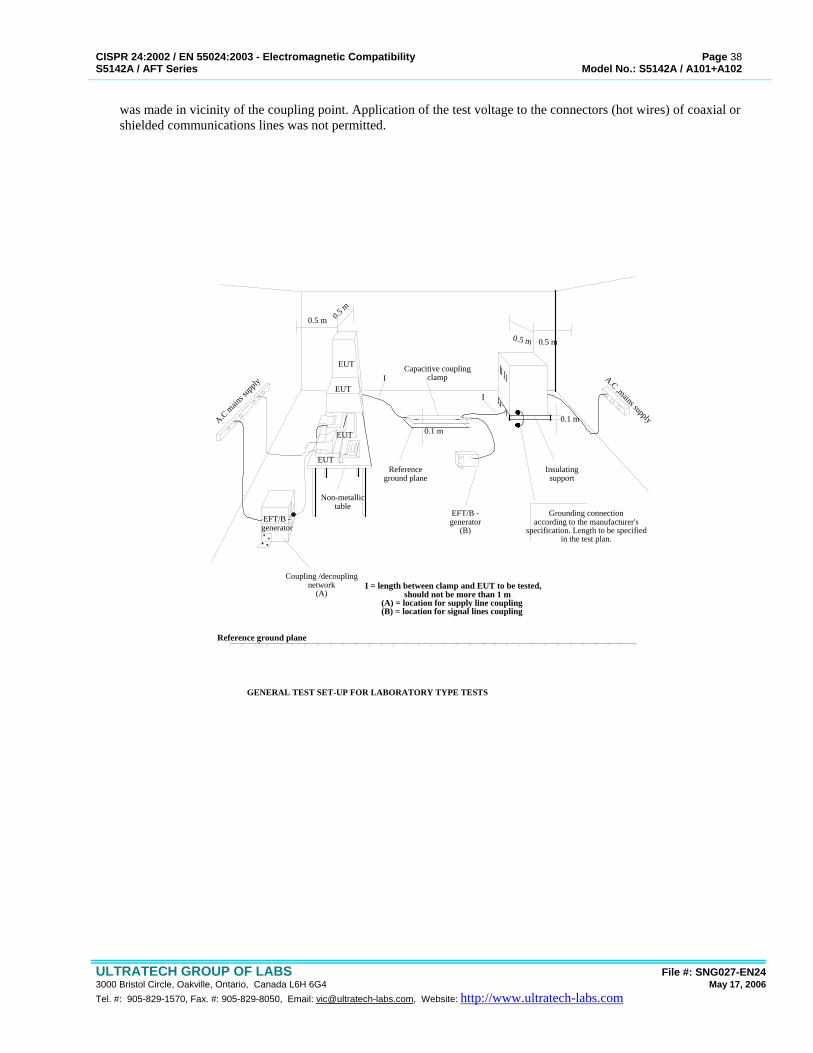
CISPR 24:2002 / EN 55024:2003 - Electromagnetic Compatibility Page 38 S5142A / AFT Series Model No.: S5142A / A101+A102
ULTRATECH GROUP OF LABS File #: SNG027-EN24 3000 Bristol Circle, Oakville, Ontario, Canada L6H 6G4 May 17, 2006 Tel. #: 905-829-1570, Fax. #: 905-829-8050, Email: [email protected], Website: http://www.ultratech-labs.com
was made in vicinity of the coupling point. Application of the test voltage to the connectors (hot wires) of coaxial or shielded communications lines was not permitted.
Non-metallictable
Coupling /decouplingnetwork
(A)
EUT
EUT
EUT
EUT
EFT/B -generator
0.5 m 0.5 m
0.5 m 0.5 m
ICapacitive coupling
clamp
I
Referenceground plane
EFT/B -generator
(B)
Insulatingsupport
0.1 m
Grounding connectionaccording to the manufacturer's
specification. Length to be specifiedin the test plan.
A.C ,mains supplyA.C main
s sup
ply
0.1 m
GENERAL TEST SET-UP FOR LABORATORY TYPE TESTS
I = length between clamp and EUT to be tested, should not be more than 1 m
(A) = location for supply line coupling(B) = location for signal lines coupling
Reference ground plane
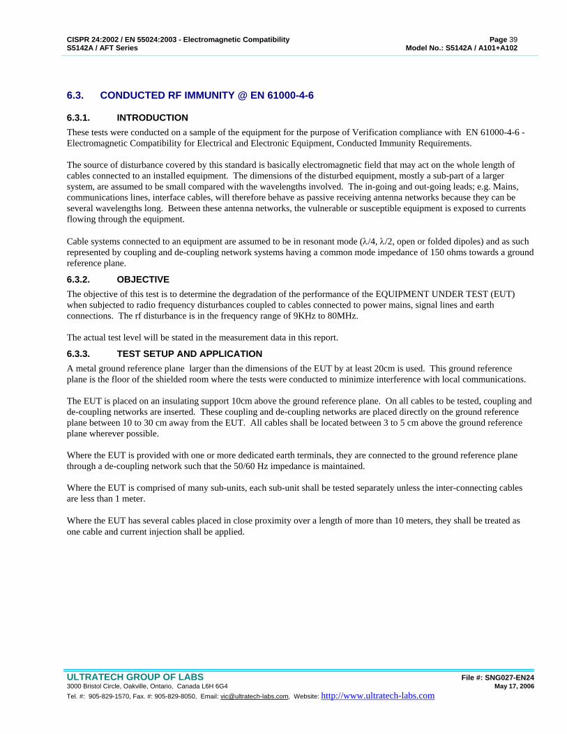
CISPR 24:2002 / EN 55024:2003 - Electromagnetic Compatibility Page 39 S5142A / AFT Series Model No.: S5142A / A101+A102
ULTRATECH GROUP OF LABS File #: SNG027-EN24 3000 Bristol Circle, Oakville, Ontario, Canada L6H 6G4 May 17, 2006 Tel. #: 905-829-1570, Fax. #: 905-829-8050, Email: [email protected], Website: http://www.ultratech-labs.com
6.3. CONDUCTED RF IMMUNITY @ EN 61000-4-6
6.3.1. INTRODUCTION These tests were conducted on a sample of the equipment for the purpose of Verification compliance with EN 61000-4-6 - Electromagnetic Compatibility for Electrical and Electronic Equipment, Conducted Immunity Requirements. The source of disturbance covered by this standard is basically electromagnetic field that may act on the whole length of cables connected to an installed equipment. The dimensions of the disturbed equipment, mostly a sub-part of a larger system, are assumed to be small compared with the wavelengths involved. The in-going and out-going leads; e.g. Mains, communications lines, interface cables, will therefore behave as passive receiving antenna networks because they can be several wavelengths long. Between these antenna networks, the vulnerable or susceptible equipment is exposed to currents flowing through the equipment. Cable systems connected to an equipment are assumed to be in resonant mode (λ/4, λ/2, open or folded dipoles) and as such represented by coupling and de-coupling network systems having a common mode impedance of 150 ohms towards a ground reference plane.
6.3.2. OBJECTIVE The objective of this test is to determine the degradation of the performance of the EQUIPMENT UNDER TEST (EUT) when subjected to radio frequency disturbances coupled to cables connected to power mains, signal lines and earth connections. The rf disturbance is in the frequency range of 9KHz to 80MHz. The actual test level will be stated in the measurement data in this report.
6.3.3. TEST SETUP AND APPLICATION A metal ground reference plane larger than the dimensions of the EUT by at least 20cm is used. This ground reference plane is the floor of the shielded room where the tests were conducted to minimize interference with local communications. The EUT is placed on an insulating support 10cm above the ground reference plane. On all cables to be tested, coupling and de-coupling networks are inserted. These coupling and de-coupling networks are placed directly on the ground reference plane between 10 to 30 cm away from the EUT. All cables shall be located between 3 to 5 cm above the ground reference plane wherever possible. Where the EUT is provided with one or more dedicated earth terminals, they are connected to the ground reference plane through a de-coupling network such that the 50/60 Hz impedance is maintained. Where the EUT is comprised of many sub-units, each sub-unit shall be tested separately unless the inter-connecting cables are less than 1 meter. Where the EUT has several cables placed in close proximity over a length of more than 10 meters, they shall be treated as one cable and current injection shall be applied.
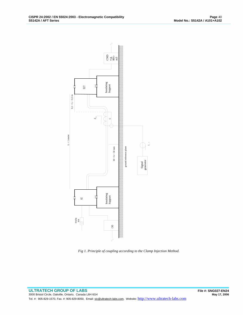
CISPR 24:2002 / EN 55024:2003 - Electromagnetic Compatibility Page 40 S5142A / AFT Series Model No.: S5142A / A101+A102
ULTRATECH GROUP OF LABS File #: SNG027-EN24 3000 Bristol Circle, Oakville, Ontario, Canada L6H 6G4 May 17, 2006 Tel. #: 905-829-1570, Fax. #: 905-829-8050, Email: [email protected], Website: http://www.ultratech-labs.com
Insu
latin
gSu
ppor
tIn
sula
ting
Supp
ort
AEEU
T
CND
CN
De.
g.80
1-m
3
Sign
alge
nera
tor
decoup
lingferr
ite
grou
nd re
fere
nce
plan
e
U 050
Z CE
30 <
h <
50
mm
0,1
< L
< 0,
3 m
L <
1 m
etre
C1
Fig 1. Principle of coupling according to the Clamp Injection Method.
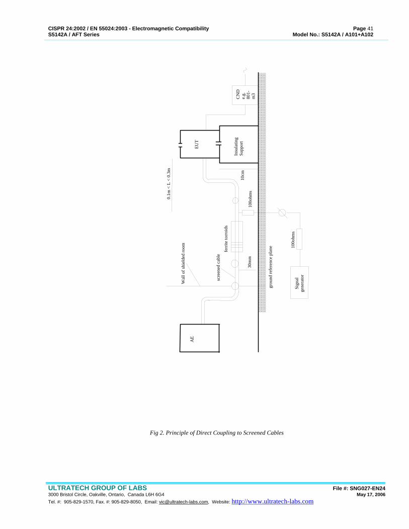
CISPR 24:2002 / EN 55024:2003 - Electromagnetic Compatibility Page 41 S5142A / AFT Series Model No.: S5142A / A101+A102
ULTRATECH GROUP OF LABS File #: SNG027-EN24 3000 Bristol Circle, Oakville, Ontario, Canada L6H 6G4 May 17, 2006 Tel. #: 905-829-1570, Fax. #: 905-829-8050, Email: [email protected], Website: http://www.ultratech-labs.com
Insu
latin
gSu
ppor
t
AE
EUT
CN
De.
g.80
1-m
3
Sign
alge
nera
tor
grou
nd re
fere
nce
plan
e
30m
m
0.1m
< L
< 0
.3m
10cm
100o
hms
100o
hms
ferr
ite to
rroi
ds
Wal
l of s
hiel
ded
room
scre
ened
cab
le
Fig 2. Principle of Direct Coupling to Screened Cables
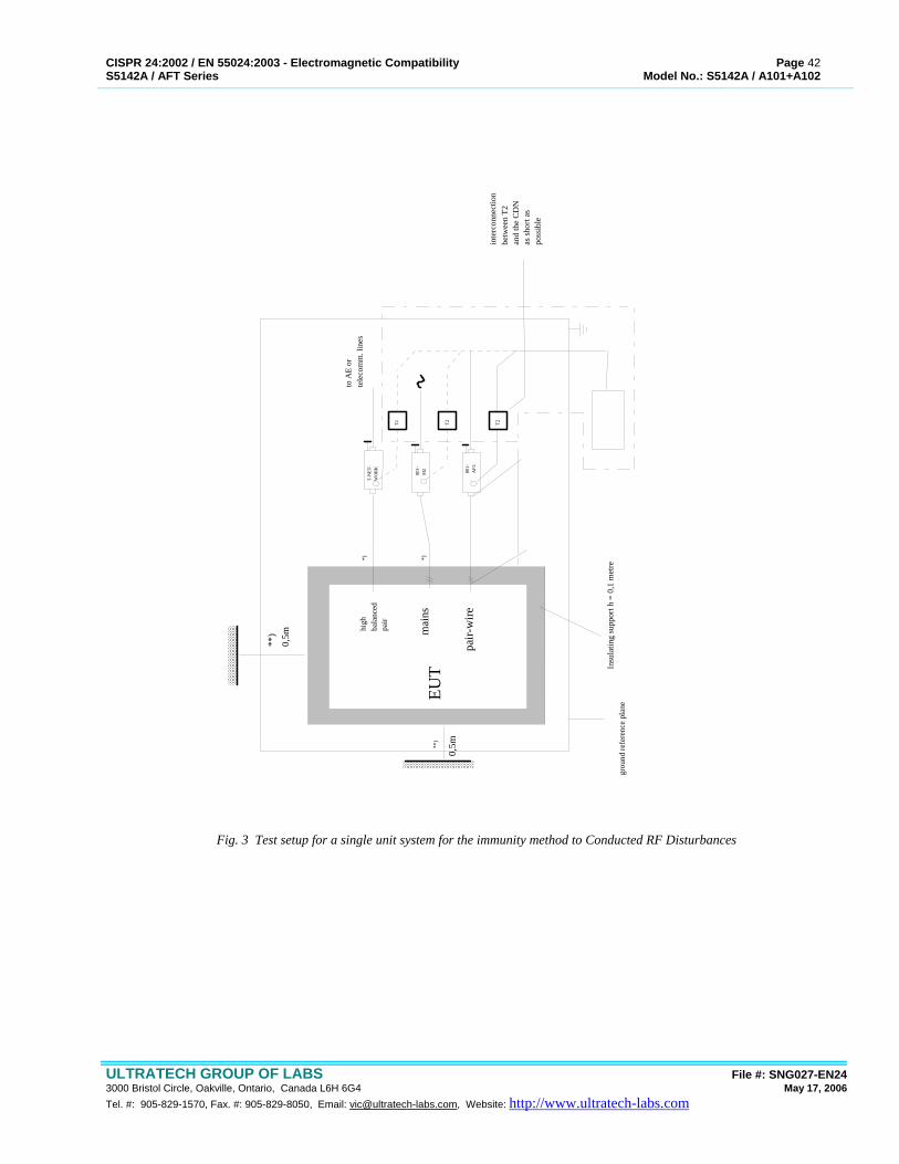
CISPR 24:2002 / EN 55024:2003 - Electromagnetic Compatibility Page 42 S5142A / AFT Series Model No.: S5142A / A101+A102
ULTRATECH GROUP OF LABS File #: SNG027-EN24 3000 Bristol Circle, Oakville, Ontario, Canada L6H 6G4 May 17, 2006 Tel. #: 905-829-1570, Fax. #: 905-829-8050, Email: [email protected], Website: http://www.ultratech-labs.com
T2 T2 T2
to A
E or
tele
com
m. l
ines
inte
rcon
nect
ion
betw
een
T2an
d th
e C
DN
as sh
ort a
s po
ssib
le
T-N
ET-
WO
RK
801-
M2 80
1-A
F2
**)
0,5m
high
bala
nced
pair
mai
ns
pair-
wire
EUT
**)
0,5m
*) *)
Insu
latin
g su
ppor
t h =
0,1
met
regr
ound
refe
renc
e pl
ane
Fig. 3 Test setup for a single unit system for the immunity method to Conducted RF Disturbances
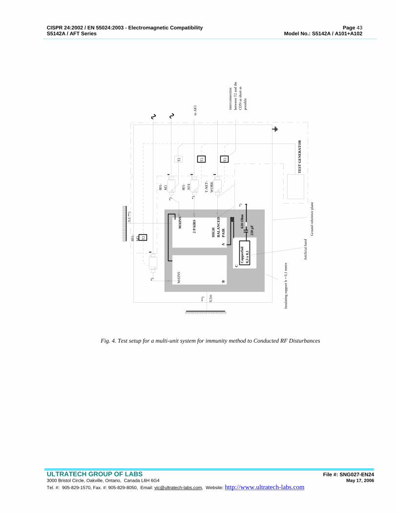
CISPR 24:2002 / EN 55024:2003 - Electromagnetic Compatibility Page 43 S5142A / AFT Series Model No.: S5142A / A101+A102
ULTRATECH GROUP OF LABS File #: SNG027-EN24 3000 Bristol Circle, Oakville, Ontario, Canada L6H 6G4 May 17, 2006 Tel. #: 905-829-1570, Fax. #: 905-829-8050, Email: [email protected], Website: http://www.ultratech-labs.com
T2 T2 T2
T2
0,5
**)
*) *)
*)
**)
*)
0,5m
MA
INS
BA
C
MA
INS
2 PA
IRS
HIG
HB
AL
AN
CE
DPA
IR
Cop
perf
oil
0,3
x 0,
122
0 pF61
0 O
hm
TE
ST G
EN
ER
AT
OR
to A
E1 inte
rcon
nect
ion
betw
een
T2 a
nd th
e C
DN
as s
hort
aspo
ssib
le
Insu
latin
g su
ppor
t h =
0,1
met
re
Arti
ficia
l han
d
Gro
und
refe
renc
e pl
ane
801-
M3
801-
AF4
T-N
ET-
WO
RK
801-
M3
Fig. 4. Test setup for a multi-unit system for immunity method to Conducted RF Disturbances
CISPR 24:2002 / EN 55024:2003 - Electromagnetic Compatibility Page 44 S5142A / AFT Series Model No.: S5142A / A101+A102
ULTRATECH GROUP OF LABS File #: SNG027-EN24 3000 Bristol Circle, Oakville, Ontario, Canada L6H 6G4 May 17, 2006 Tel. #: 905-829-1570, Fax. #: 905-829-8050, Email: [email protected], Website: http://www.ultratech-labs.com
6.4. POWER MAGNETIC FIELD IMMUNITY @ EN 61000-4-8
6.4.1. INTRODUCTION These tests were conducted on a sample of the equipment for the purpose of Verification compliance with International Standard IEC 61000-4-8 - Electromagnetic Compatibility - Power Frequency Magnetic Field Immunity.
6.4.2. OBJECTIVE To determine the effect of power line magnetic fields on the device under test in conformance with IEC 61000-4-8 - Electromagnetic Compatibility - Power Frequency Magnetic Field Immunity.
6.4.3. THE SEVERITY LEVELS TO BE MET ARE AS FOLLOWS:
FREQUENCY
(Hz) MAGNETIC FIELD
(A/m) DEGRADATION ALLOWED
50 Hz 3.0 No degradation allowed 50 Hz 30.0 CRT display interference allowed
6.5. TEST APPLICATION AND SETUP
6.5.1. TEST METHOD #1: USING A HELMHOLTZ COIL. The magnetic field produced in a Helmholtz Coil is uniform and a well known function of the coils radius and coil current given by the following: H = 8NI A/m r*sqrt(125) where: H: Magnetic Field in A/m I: Current present in coil in amps N: Number of turns in each coil R: Radius of Coil in meters The Helmholtz coil used has the following characteristics: r = 0.5 m, N = 103 The relationship between H and I is therefore given by: H = 8*(103)*I A/m = 147.4*I 0.5*sqrt(125)
H(dBuA/m) = I(dBuA) + 43.37dB For example: for H = 30 A/m, I = 106.2 dBuA or 203.5 mA The current present in the Helmholtz Coil was monitored using a calibrated current probe connected to a spectrum analyzer display. The following general provisions applied: • The EUT was place at the center of the Helmholz Coil. • The purity of the signal power delivered to the Helmholz Coil was such that it did not affect the uniformity nor the
CISPR 24:2002 / EN 55024:2003 - Electromagnetic Compatibility Page 45 S5142A / AFT Series Model No.: S5142A / A101+A102
ULTRATECH GROUP OF LABS File #: SNG027-EN24 3000 Bristol Circle, Oakville, Ontario, Canada L6H 6G4 May 17, 2006 Tel. #: 905-829-1570, Fax. #: 905-829-8050, Email: [email protected], Website: http://www.ultratech-labs.com
frequency of the magnetic field. • At frequencies where EUT was found to respond most to the generated magnetic field, a sufficient time was spent at
these sensitive frequencies to record the full immunity response. • Cables connected to the EUT were fixed in position typical of an installed situation using non-reflective test fixtures. • The EUT was operated at full load with DC output voltage level and current monitored by digital True RMS meters. • The indicator LEDs, DC output current and voltage were monitored for any unexpected changes subjected to the
presence of Magnetic Fields produced by a Helmholtx coil. • The signal source frequency was slowly varied through the required frequency range. When this activity was performed
in discrete steps, manual scanning would be performed around worst case points until the worst case frequency value was obtained.
6.5.2. TEST METHOD #2: USING AN INDUCTION COIL, REF. IEC 61000-4-8, PARA. 6.2.1 The induction coil, connected to the test generator, was used to generate a field strength corresponding to the selected test level and the define homogeneity. The single, square induction coil is made of copper material, of such cross-section and mechanical arrangement as to facilitate its stable positioning during tests. The induction coil dimensions are adjustable to envelop the EUT at different size; the coil dimensions are such as to give a minimum distance of coil inductors to EUT walls equal to 1/3 of the dimension of the EUT considered. The test volume is determined by the testing area of the coil (60%x60% of each side) multiplied by a depth corresponding to 50% of the shorter side of the coil. Calibration of the Induction Coil, Coil Factor The induction coil is calibrated in their operating condition, before conducting the test (without the EUT, in free space condition). The EUT with the correct dimensions for the EUT dimensions, is positioned at 1m minimum distance from the wall of the laboratory and any magnetic material, by using insulating supports, and is connected to the test generator. The magnetic field sensor is used to verify the magnetic field strength generated by the induction coil. The field sensor is positioned at the center of the induction coil (without the EUT) and with suitable orientation to detect the maximum value of the field. The current in the induction coil is adjusted to obtained the field strength specified by the test level. The calibration is carried out at the power frequency (50 Hz).
CISPR 24:2002 / EN 55024:2003 - Electromagnetic Compatibility Page 46 S5142A / AFT Series Model No.: S5142A / A101+A102
ULTRATECH GROUP OF LABS File #: SNG027-EN24 3000 Bristol Circle, Oakville, Ontario, Canada L6H 6G4 May 17, 2006 Tel. #: 905-829-1570, Fax. #: 905-829-8050, Email: [email protected], Website: http://www.ultratech-labs.com
EXHIBIT 7. LABELLING REQUIREMENTS
The CE Mark with respect to the EMC Directive 89/336/EEC
>5mm
The CE mark shall consist of the initials “CE” taking the following form
• If the CE marking is reduced or enlarged, the proportions given in the above graduated drawing must be respected.
• Where apparatus is the subject of other Directives covering other aspects and which also provide for the CE conformity marking, the latter shall indicate that the appliances are also presumed to conform to those other Directives.
• However, where one or more of these Directives allow the manufacturer, during a transitional period, to choose which arrangements to apply, the CE mark shall indicate conformity only to the Directives applied by the manufacturer. In this case, particulars of the Directive applied, as published in the Official Journal of the European Communities, must be given in the documents, notices or instructions required by the Directives and accompanying such apparatus.
The various components of the CE marking must have substantially the same vertical dimension, which may not be less than 5mm.
CISPR 24:2002 / EN 55024:2003 - Electromagnetic Compatibility Page 47 S5142A / AFT Series Model No.: S5142A / A101+A102
ULTRATECH GROUP OF LABS File #: SNG027-EN24 3000 Bristol Circle, Oakville, Ontario, Canada L6H 6G4 May 17, 2006 Tel. #: 905-829-1570, Fax. #: 905-829-8050, Email: [email protected], Website: http://www.ultratech-labs.com

CISPR 24:2002 / EN 55024:2003 - Electromagnetic Compatibility Page 48 S5142A / AFT Series Model No.: S5142A / A101+A102
ULTRATECH GROUP OF LABS File #: SNG027-EN24 3000 Bristol Circle, Oakville, Ontario, Canada L6H 6G4 May 17, 2006 Tel. #: 905-829-1570, Fax. #: 905-829-8050, Email: [email protected], Website: http://www.ultratech-labs.com