ultrasonic evaluation at the interface of aluminum/steel obtained … · 2019-08-30 ·...
TRANSCRIPT
Content from this work may be used under the terms of the Creative Commons Attribution 3.0 licence. Any further distribution
of this work must maintain attribution to the author(s) and the title of the work, journal citation and DOI.
Published under licence by IOP Publishing Ltd
Malaysia International NDT Conference and Exhibition 2018
IOP Conf. Series: Materials Science and Engineering 554 (2019) 012010
IOP Publishing
doi:10.1088/1757-899X/554/1/012010
1
Ultrasonic Evaluation at the Interface of Aluminum/Steel
Obtained by TIG Welding
Qumrul Ahsan1 & Hiroshi Kato2
1Carbon Research Technology Group, Advanced Manufacturing Centre, Faculty of
Manufacturing Engineering, Universiti Teknikal Malaysia Melaka, Hang Tuah Jaya,
76100 Durian Tunggal, Melaka, Malaysia. 2Department of Mechanical Engineering, Division of Mechanical Science and
Engineering, Saitama University, 255 Shimo-Okubo, Sakura-ku, Saitama-city,
Saitama 338-8570, Japan
Corresponding author, email: [email protected]
Abstract. Aluminum filler (Al-5%Si) is bonded on steel substrate by gas tungsten arc
welding process under different current setting conditions. After welding a thorough
metallographic analyses using optical and scanning electron microscopy were carried
out to observe Al-Steel interface. Ultrasonic measurements by immersion and scanning
acoustic microscopy were made to characterise the bond at Al-Steel interface. The
ultrasonic wave reflected from the Al-Steel interface clearly indicated the more
debonded area when the welding current is changed from direct current straight polarity
(DCSP) mode to alternate current high frequency (ACHF) or the welding current in case
of current for DCSP mode is reduced. This may be attributed either adequate amount of
oxides along with intermediate phase make the bond interface rough and uneven due to
introduction of ACHF mode or debonded areas are higher due to lower heat input when
the current reduced to 125 amps from 150 amps in DCSP mode. Whereas smooth and
even bond interface due to uniform heat input resulted stable Al-Steel interface and the
mapping of bonded area by ultrasonic measurement showed spectrum of minimum peak
for using current of 150 amps in DC mode. Thus the non-destructive assessments of
interface between dissimilar materials through ultrasonic measurements could be
important tools for evaluating the state of the bond.
1. Introduction
Aluminum and its alloys are widely used in fabrications because of their lightweight, good corrosion
resistance and weldability. The unique combination of light weight and relatively high strength makes
aluminum the second most popular metal that is welded. Light weight engineering structures are the
prime concerns for automobile and shipbuilding industries. To reduce the weight of the structural
components the combination of steel and aluminum alloy fabrication is considered to be an efficient
measure. Several welding methods viz. explosive bonding or rolling [1] solid-phase bonding methods,
such as friction welding [2], ultrasonic joining [3], rolling [4] and laser method [5, 6] are being utilized
to join steel and aluminum. The investigations made by Yan eta. [5] clearly indicated the microstructural
segregation at the interface of steel-Al joints clearly produced Fe-Al intermetallic compounds (IMCs),
such as Fe2Al5, FeAl3 and FeAl, that may improve the hardness of the interface layer dramatically but
Mor
e in
fo a
bout
this
art
icle
: ht
tp://
ww
w.n
dt.n
et/?
id=
2469
1
Malaysia International NDT Conference and Exhibition 2018
IOP Conf. Series: Materials Science and Engineering 554 (2019) 012010
IOP Publishing
doi:10.1088/1757-899X/554/1/012010
2
reduce and ductility of weldment with increased susceptibility of solidification cracking in the fusion
zone. Studies on friction stir welding (FSW) [7-11] for steel/aluminum weld have also been reported
and the results show that the FSW joints exhibit superior mechanical and chemical properties compared
to gas tungsten arc welding (GTAW) joints due to the presence of finer grains the weld metal of FSW
joints. Many attempts have also been made so far to deposit aluminum alloy on commercial grade steel
substrates by fusion welding process [12, 13]. Studies from Pouranvari et.al [12] indicated that low heat
input rate of GTAW process reduce the growth of intermetallic compounds during joining. In a different
study Su et. al. [13] prepared Al–steel lap joints from direct-current pulsed gas metal arc welding (DPG)
and alternate-current double-pulse gas metal arc welding (ADG) and showed that ADG process offers
higher joint strength than that offered by DPG process due to thinner intermetallic compounds layer
resulted from lower heat input.
However, sound joints are difficult to produce, because hard and brittle intermetallic compounds are
formed at the weld whenever steel is welded to aluminum by fusion welding. The reason for this is
attributed to the large difference between their melting points (933 K for Al and 1811 K for Fe), the very
few solid solubility of iron in aluminum, and the formation of brittle intermetallic compounds such as
Fe2Al5 and FeAl3 [14]. Further, differences in their thermal properties like expansion coefficients,
conductivities, and specific heats lead to internal stresses after fusion welding. In addition, presence of
oxide layers during welding at steel aluminum interface can cause debonding. Therefore, fusion welds
of iron and aluminum suffer from cracking with brittle failure in service [14]. Quality control of steel-
aluminum weldment is considered as the prime concern for the fabrication industries. Tools and
techniques especially utilization of ultrasound in non-destructive evaluation is widely used to ensure the
proper quality of the weldment.
Cracks, formation of pores and other discontinuities in deposit are also of great concern to determine.
A very efficient method for detecting these defects and measuring layer thickness is the ultrasonic
method [15] and this can lead to strong effects on the ultrasonic properties. Hudgell [16] gave a
description of austenitic clad components and of the ultrasonic testing of such components.
Investigations into the energy aspect of the reflectivity for the lamination-type flaws show that the
energy reflected depends on the specific wave resistance of the layers involved and the kind of substance
filling the space between them, as well as on the ratio of flaw thickness and ultrasonic wave length.
Generally, in the case of flaws of delamination type, the reflectivity increases and this increase is used
as the basis for the ultrasonic flaw detection methods.
In the present work, ultrasonic measurements were carried out to evaluate the bond interface of steel
and aluminum at different welding conditions. Welding in steel substrate with Al-5% Si alloy as filler
is manually carried out at different current settings under constant welding speed through welding torch.
Studies have been carried out to obtain the relationships between the state of the bonding interface and
ultrasonic parameters, such as the transmissibility (or reflectivity) of an ultrasonic wave at the bonding
interface and an ultrasonic waveform traveling through the interface.
2. Experimental
2.1. Preparation of specimen
In this study, steel plates were used to make weld bead deposit of Al alloy on it. The chemical analysis
of the plate was carried out by optical emission spectroscopy (OES) and the result found from OES is
given in Table 1. From the OES result, it was found that the steel plate is simple grade of mild steel. The
mild steel plates were machined to the required dimensions of 75 mm × 50 mm × 8 mm. First the
contaminants and oxide film on the steel surface were removed by steel brush. Final cleaning of the steel
faying surface was carried out by acid pickling using 5% hydrochloric acid for 10-12 minutes.
Malaysia International NDT Conference and Exhibition 2018
IOP Conf. Series: Materials Science and Engineering 554 (2019) 012010
IOP Publishing
doi:10.1088/1757-899X/554/1/012010
3
Table 1. Chemical composition in wt.% of steel plate and Al filler used in this investigation. (OES)
An A4043 (Al-5%Si) grade filler rod was used for gas tungsten arc welding (GTAW) process, and
single pass welding was used to deposit aluminum weld bead on steel surface. The welding procedure
was carried out by a certified welder. The plates were clamped and welded manually in the flat position
using Al-5% Si filler metals at different welding currents with constant welding speed. High purity
(99.99%) argon shielding gas with a flow rate of 15 liter/min was used in all welding trials. The welding
current modes for ACHF and DCSP with welding parameters are presented in Table 2 to fabricate
aluminum-steel (Al/Steel) clad in this study. Usually DC welding is the preferred type of welding either
using direct current straight polarity (electrode negative) or direct current reverse polarity (electrode
positive) to produce a smoother weld than AC. As DC delivers a constant and consistent current it is
expected that welding of aluminum on steel substrate may produce a smoother interface with thin
intermetallic layer. Whereas, when using AC, the current swings with changing polarity and causing
fluctuation in arc which may disrupt the aluminum steel interface with higher chance of making the
bond interface rough and uneven. The welding heat input rate (Qw) for both DCSP and ACHF was
calculated using following formula [17]:
S
VIQ
w
(1)
where, V is the arc voltage, I is the welding current, S is the welding speed (measured as the welding
process [17]).
Table 2. Welding conditions and process parameters
Sample ID Welding
Process
Welding
Mode
Current
Freq.
(Hz)
Average
Voltage
(V)
Average
Current
(A)
Welding
Speed S
(mm/min)
Heat Input
Qw (kJ/mm)
ACHF 150 GTAW ACHF 50 15 150 60 540
DCSP 150 GTAW DCSP - 15 150 60 540
DCSP 125 GTAW DCSP - 15 125 60 450
After welding, the welded plates were cooled in air. Aluminum weld deposit for each sample was
machined by milling cutter to make it around 2 mm thick. The steel substrate of each sample was also
machined to make smooth and parallel surface with aluminum surface, and the thickness of the steel
was made to around 7 mm thick.
2.2. Ultrasonic measurement
In order to characterize the aluminum-steel interface, the ultrasonic measurement by immersion method
and the scanning acoustic microscope along were used. An experimental setup of ultrasonic
measurement by immersion methods is shown in Fig. 1. The transducer of 10 mm diameter generating
a longitudinal wave of 20 MHz in frequency with a focal distance of 25.4 mm in water was used. A
distance between the transducer and the specimen (water path) was controlled so that the ultrasonic
Materials Elements (in wt. %)
C Si Mn Cu Fe Al
Mild Steel Plate 0.13 0.09 0.5 <0.01 bal
Al-4043 filler - 4.5 - 5.0 - <0.3 - bal
Malaysia International NDT Conference and Exhibition 2018
IOP Conf. Series: Materials Science and Engineering 554 (2019) 012010
IOP Publishing
doi:10.1088/1757-899X/554/1/012010
4
wave was focused at the steel–aluminum interface. In each sample, the ultrasonic measurement was
carried out at 10 x 10 scanning points in an area of 9 x 9 mm with a pitch of 1 mm by irradiating the
ultrasonic wave from steel side, whereas scans were made on 20 points in a linear distance with a pitch
of 1 mm from the aluminum side for same sample. In this method, the probe was kept constant distance
from the surface of the object to be inspected, and scanned the surface to detect irregularities of the
interface.
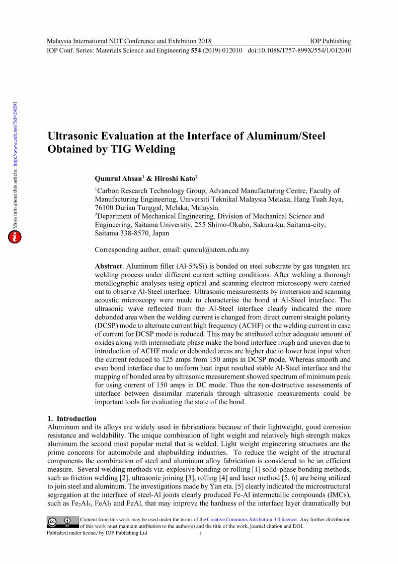
Figure 1. Experimental set up of ultrasonic C-scan system for immersion scanning.
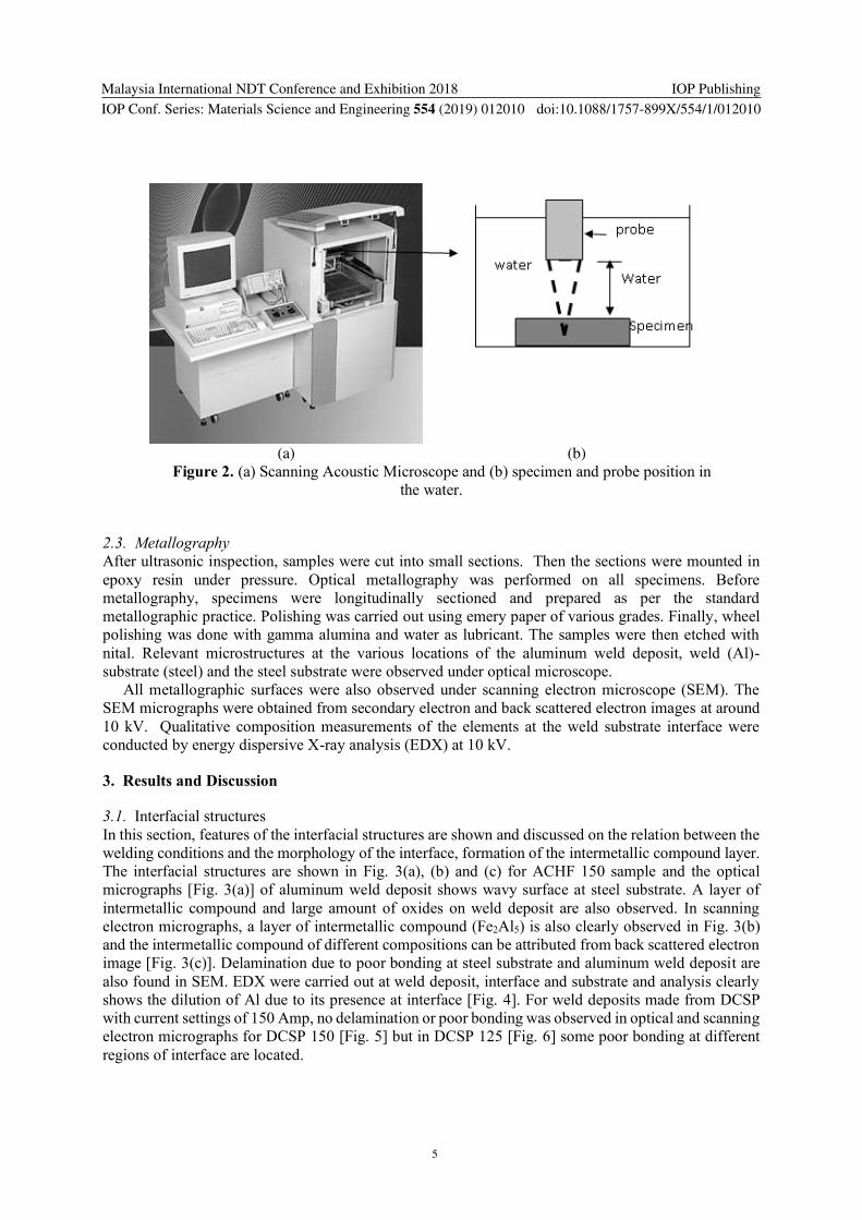
Scanning acoustic microscope (SAM) as shown in Fig. 2 was used to obtain acoustic intensity image
from the aluminum side with a probe generating a wave of 50 MHz in frequency with a focal distance
of 10 mm in water to produce high resolution images at the aluminum-steel interface, and interfacial
separation and irregularities at weld interface were detected. In the present analysis, the maps of an area
of 18 mm x 18 mm were obtained at six different locations and combined for each sample. The absolute
value of the highest amplitude signal within the gated region was recorded.
Malaysia International NDT Conference and Exhibition 2018
IOP Conf. Series: Materials Science and Engineering 554 (2019) 012010
IOP Publishing
doi:10.1088/1757-899X/554/1/012010
5
(a) (b)
Figure 2. (a) Scanning Acoustic Microscope and (b) specimen and probe position in
the water.
2.3. Metallography
After ultrasonic inspection, samples were cut into small sections. Then the sections were mounted in
epoxy resin under pressure. Optical metallography was performed on all specimens. Before
metallography, specimens were longitudinally sectioned and prepared as per the standard
metallographic practice. Polishing was carried out using emery paper of various grades. Finally, wheel
polishing was done with gamma alumina and water as lubricant. The samples were then etched with
nital. Relevant microstructures at the various locations of the aluminum weld deposit, weld (Al)-
substrate (steel) and the steel substrate were observed under optical microscope.
All metallographic surfaces were also observed under scanning electron microscope (SEM). The
SEM micrographs were obtained from secondary electron and back scattered electron images at around
10 kV. Qualitative composition measurements of the elements at the weld substrate interface were
conducted by energy dispersive X-ray analysis (EDX) at 10 kV.
3. Results and Discussion
3.1. Interfacial structures
In this section, features of the interfacial structures are shown and discussed on the relation between the
welding conditions and the morphology of the interface, formation of the intermetallic compound layer.
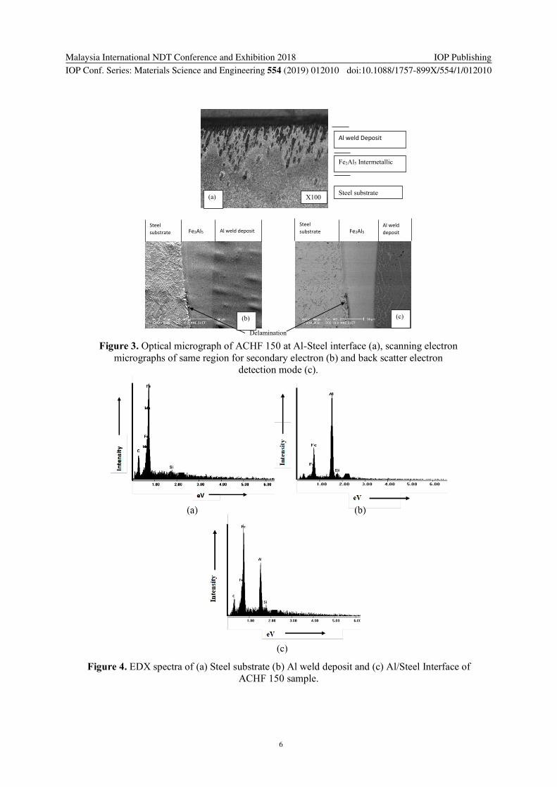
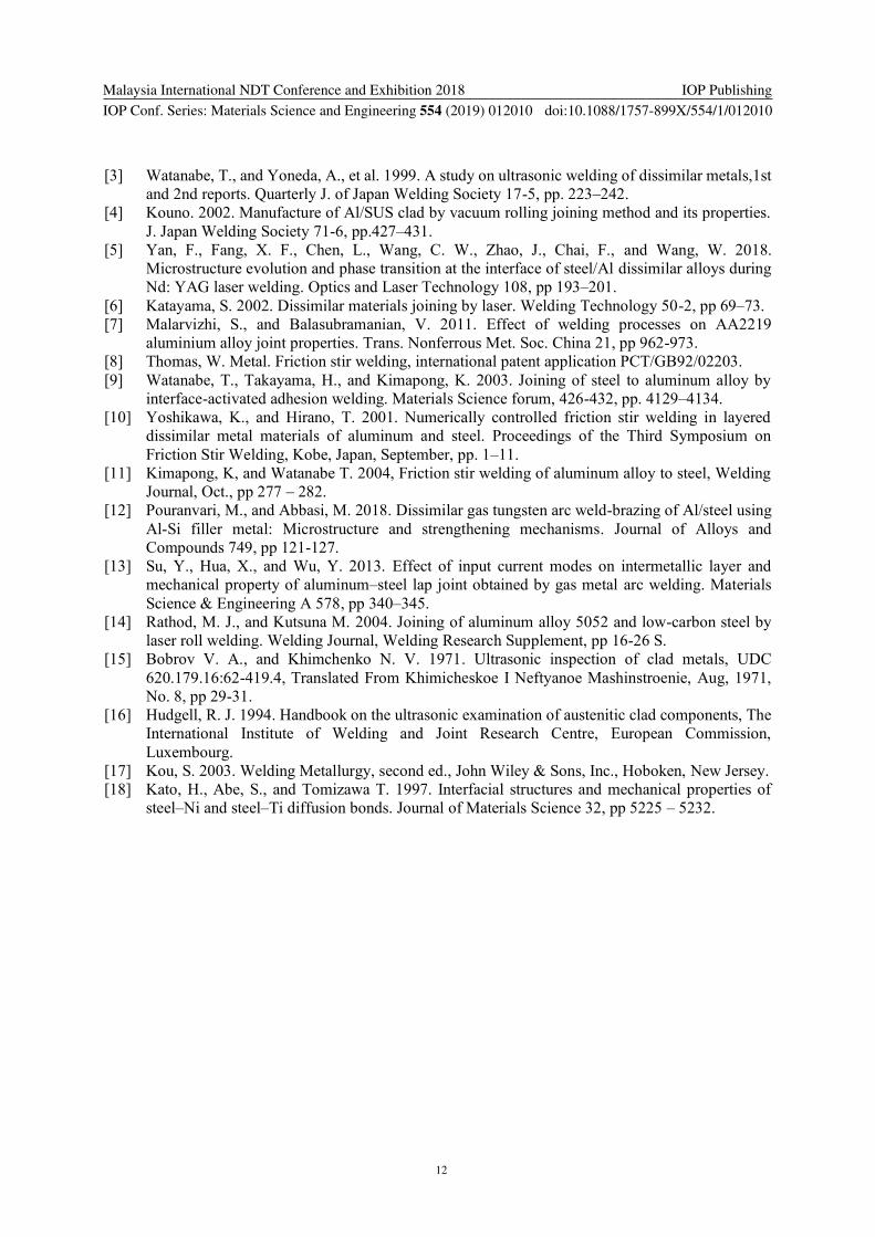
The interfacial structures are shown in Fig. 3(a), (b) and (c) for ACHF 150 sample and the optical
micrographs [Fig. 3(a)] of aluminum weld deposit shows wavy surface at steel substrate. A layer of
intermetallic compound and large amount of oxides on weld deposit are also observed. In scanning
electron micrographs, a layer of intermetallic compound (Fe2Al5) is also clearly observed in Fig. 3(b)
and the intermetallic compound of different compositions can be attributed from back scattered electron
image [Fig. 3(c)]. Delamination due to poor bonding at steel substrate and aluminum weld deposit are
also found in SEM. EDX were carried out at weld deposit, interface and substrate and analysis clearly
shows the dilution of Al due to its presence at interface [Fig. 4]. For weld deposits made from DCSP
with current settings of 150 Amp, no delamination or poor bonding was observed in optical and scanning
electron micrographs for DCSP 150 [Fig. 5] but in DCSP 125 [Fig. 6] some poor bonding at different
regions of interface are located.
Malaysia International NDT Conference and Exhibition 2018
IOP Conf. Series: Materials Science and Engineering 554 (2019) 012010
IOP Publishing
doi:10.1088/1757-899X/554/1/012010
6
Figure 4. EDX spectra of (a) Steel substrate (b) Al weld deposit and (c) Al/Steel Interface of
ACHF 150 sample.
Figure 3. Optical micrograph of ACHF 150 at Al-Steel interface (a), scanning electron
micrographs of same region for secondary electron (b) and back scatter electron
detection mode (c).
Delamination
Al weld Deposit
Fe2Al5 Intermetallic
Steel substrate
Steel
substrate Fe2Al5 Al weld deposit
Steel
substrate Fe2Al5 Al weld
deposit
X100 (a)
(b) (c)
Malaysia International NDT Conference and Exhibition 2018
IOP Conf. Series: Materials Science and Engineering 554 (2019) 012010
IOP Publishing
doi:10.1088/1757-899X/554/1/012010
7
(a) (b)
Figure 5. (a) Optical micrograph of Al-Steel interface of DCSP 150 sample and (b)
scanning electron micrographs of same region.
(a) (b)
Figure 6. (a) Optical micrograph of Al-Steel interface of DCSP 125 sample and (b)
scanning electron micrographs of same region.
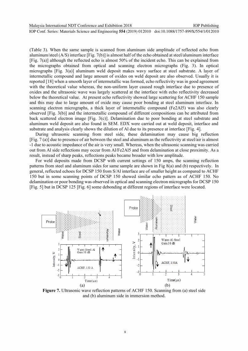
3.2. Relation between ultrasonic wave intensity and irregularity of interface
In this part, the results of the ultrasonic measurement are shown, and the relation between the ultrasonic
wave reflected from the surface, the interface and the bottom and the features of the interface are
discussed. In immersion method ultrasonic scanning were carried out from both the steel side and
aluminum side for three different weld conditions. In order to determine the reflection nature from
interfaces the acoustic impedances and the calculated reflected wave ratios at different interfaces are
given in Table 3.
Table 3. Acoustic impedance and reflected wave ratios at different interfaces.
Acoustic Impedance, kg/m2-s Reflected wave ratio at interface of
Water (W) Steel (S) Aluminum (Al) W/S S/Al Al/W
1.50 x 10⁶ 4.54 x 10⁷ 1.71 x 10⁷ 0.936 -0.453 -0.839
In case of weld deposit made from ACHF 150, the ultrasonic scanning reflection patterns from steel
and aluminum sides are shown in Fig 7 (a) and (b) respectively. From steel side the first peak echo at
water/steel (W/S) interface is negative whereas, the peak echoes from steel/Al (S/A) and Al/water (A/W)
interfaces are positive as the reflected wave ratios for W/S is positive and for S/A and A/W are negative
X100
X100
Malaysia International NDT Conference and Exhibition 2018
IOP Conf. Series: Materials Science and Engineering 554 (2019) 012010
IOP Publishing
doi:10.1088/1757-899X/554/1/012010
8
(Table 3). When the same sample is scanned from aluminum side amplitude of reflected echo from
aluminum/steel (A/S) interface [Fig. 7(b)] is almost half of the echo obtained at steel/aluminum interface
[Fig. 7(a)] although the reflected echo is almost 50% of the incident echo. This can be explained from
the micrographs obtained from optical and scanning electron micrographs (Fig. 3). In optical
micrographs [Fig. 3(a)] aluminum weld deposit makes wavy surface at steel substrate. A layer of
intermetallic compound and large amount of oxides on weld deposit are also observed. Usually it is
reported [18] when a smooth layer of intermetallic was formed, echo reflectivity was in good agreement
with the theoretical value whereas, the non-uniform layer caused rough interface due to presence of
oxides and the ultrasonic wave was largely scattered at the interface with echo reflectivity decreased
below the theoretical value. At present echo reflectivity showed large scattering for ACHF 150 sample
and this may due to large amount of oxide may cause poor bonding at steel aluminum interface. In
scanning electron micrographs, a thick layer of intermetallic compound (Fe2Al5) was also clearly
observed [Fig. 3(b)] and the intermetallic compound of different compositions can be attributed from
back scattered electron image [Fig. 3(c)]. Delamination due to poor bonding at steel substrate and
aluminum weld deposit are also found in SEM. EDX were carried out at weld deposit, interface and
substrate and analysis clearly shows the dilution of Al due to its presence at interface [Fig. 4].
During ultrasonic scanning from steel side, these delamination may cause big reflection
[Fig. 7 (a)] due to presence of air between the steel and aluminum as the reflectivity at steel/air is almost
-1 due to acoustic impedance of the air is very small. Whereas, when the ultrasonic scanning was carried
out from Al side reflections may occur from Al/Fe2Al5 and from delamination at close proximity. As a
result, instead of sharp peaks, reflections peaks became broader with low amplitude.
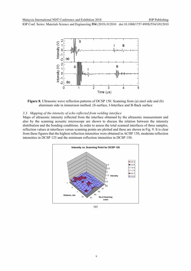
For weld deposits made from DCSP with current settings of 150 amps, the scanning reflection
patterns from steel and aluminum sides for same sample are shown in Fig 8(a) and (b) respectively. In
general, reflected echoes for DCSP 150 from S/Al interface are of smaller height as compared to ACHF
150 but in some scanning points of DCSP 150 showed similar echo pattern as of ACHF 150. No
delamination or poor bonding was observed in optical and scanning electron micrographs for DCSP 150
[Fig. 5] but in DCSP 125 [Fig. 6] some debonding at different regions of interface were located.
(a) (b)
Figure 7. Ultrasonic wave reflection patterns of ACHF 150. Scanning from (a) steel side
and (b) aluminum side in immersion method.
Malaysia International NDT Conference and Exhibition 2018
IOP Conf. Series: Materials Science and Engineering 554 (2019) 012010
IOP Publishing
doi:10.1088/1757-899X/554/1/012010
9
Figure 8. Ultrasonic wave reflection patterns of DCSP 150. Scanning from (a) steel side and (b)
aluminum side in immersion method. (S-surface, I-Interface and B-Back surface
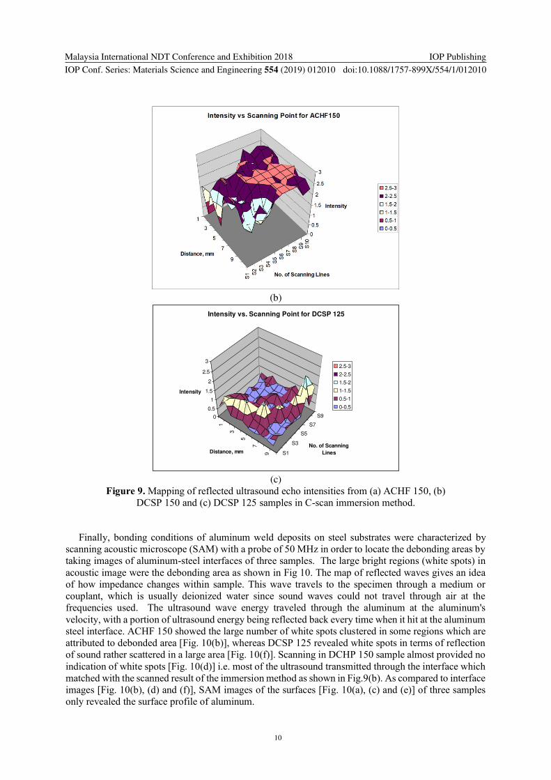
3.3. Mapping of the intensity of echo reflected from welding interface
Maps of ultrasonic intensity reflected from the interface obtained by the ultrasonic measurement and
also by the scanning acoustic microscope are shown to discuss the relation between the intensity
distribution and the bonding conditions. In order to assess the total scanned interfaces of three samples,
reflection values at interfaces versus scanning points are plotted and these are shown in Fig. 9. It is clear
from these figures that the highest reflection intensities were obtained in ACHF 150, moderate reflection
intensities in DCSP 125 and the minimum reflection intensities in DCSP 150.
(a)
1
4
7
10S1
S3
S5
S7
S90
0.5
1
1.5
2
2.5
3
Intensity
Distance, mmNo.of Scanning
Lines
Intensity vs. Scanning Point for DCSP 150
2.5-3
2-2.5
1.5-2
1-1.5
0.5-1
0-0.5
Malaysia International NDT Conference and Exhibition 2018
IOP Conf. Series: Materials Science and Engineering 554 (2019) 012010
IOP Publishing
doi:10.1088/1757-899X/554/1/012010
10
(b)
(c)
Figure 9. Mapping of reflected ultrasound echo intensities from (a) ACHF 150, (b)
DCSP 150 and (c) DCSP 125 samples in C-scan immersion method.
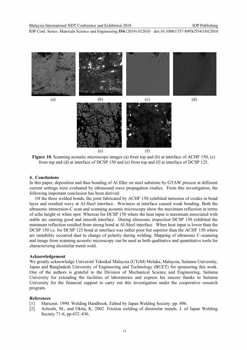
Finally, bonding conditions of aluminum weld deposits on steel substrates were characterized by
scanning acoustic microscope (SAM) with a probe of 50 MHz in order to locate the debonding areas by
taking images of aluminum-steel interfaces of three samples. The large bright regions (white spots) in
acoustic image were the debonding area as shown in Fig 10. The map of reflected waves gives an idea
of how impedance changes within sample. This wave travels to the specimen through a medium or
couplant, which is usually deionized water since sound waves could not travel through air at the
frequencies used. The ultrasound wave energy traveled through the aluminum at the aluminum's
velocity, with a portion of ultrasound energy being reflected back every time when it hit at the aluminum
steel interface. ACHF 150 showed the large number of white spots clustered in some regions which are
attributed to debonded area [Fig. 10(b)], whereas DCSP 125 revealed white spots in terms of reflection
of sound rather scattered in a large area [Fig. 10(f)]. Scanning in DCHP 150 sample almost provided no
indication of white spots [Fig. 10(d)] i.e. most of the ultrasound transmitted through the interface which
matched with the scanned result of the immersion method as shown in Fig.9(b). As compared to interface
images [Fig. 10(b), (d) and (f)], SAM images of the surfaces [Fig. 10(a), (c) and (e)] of three samples
only revealed the surface profile of aluminum.
1
3
5
7
9 S1
S3
S5
S7
S90
0.5
1
1.5
2
2.5
3
Intensity
Distance, mmNo. of Scanning
Lines
Intensity vs. Scanning Point for DCSP 125
2.5-3
2-2.5
1.5-2
1-1.5
0.5-1
0-0.5
Malaysia International NDT Conference and Exhibition 2018
IOP Conf. Series: Materials Science and Engineering 554 (2019) 012010
IOP Publishing
doi:10.1088/1757-899X/554/1/012010
11
(a) (b) (c) (d)
(e) (f)
Figure 10. Scanning acoustic microscope images (a) from top and (b) at interface of ACHF 150, (c)
from top and (d) at interface of DCSP 150 and (e) from top and (f) at interface of DCSP 125.
4. Conclusions
In this paper, deposition and thus bonding of Al filler on steel substrate by GTAW process at different
current settings were evaluated by ultrasound wave propagation studies. From this investigation, the
following important conclusion has been derived:
Of the three welded bonds, the joint fabricated by ACHF 150 exhibited intrusion of oxides in bond
layer and resulted wavy at Al-Steel interface. Waviness at interface caused weak bonding. Both the
ultrasonic immersion-C scan and scanning acoustic microscopy show the maximum reflection in terms
of echo height or white spot. Whereas for DCSP 150 where the heat input is maximum associated with
stable arc causing good and smooth interface. During ultrasonic inspection DCSP 150 exhibited the
minimum reflection resulted from strong bond at Al-Steel interface. When heat input is lower than the
DCSP 150 i.e. for DCSP 125 bond at interface was rather poor but superior than the ACHF 150 where
arc instability occurred duet to change of polarity during welding. Mapping of ultrasonic C-scanning
and image from scanning acoustic microscopy can be used as both qualitative and quantitative tools for
characterizing dissimilar metal weld.
Acknowledgement
We greatly acknowledge Universiti Teknikal Malaysia (UTeM) Melaka, Malaysia, Saitama University,
Japan and Bangladesh University of Engineering and Technology (BUET) for sponsoring this work.
One of the authors is grateful to the Division of Mechanical Science and Engineering, Saitama
University for extending the facilities of laboratories and express his sincere thanks to Saitama
University for the financial support to carry out this investigation under the cooperative research
program.
References
[1] Maruzen. 1990. Welding Handbook. Edited by Japan Welding Society: pp. 496.
[2] Aritoshi, M., and Okita, K. 2002. Friction welding of dissimilar metals. J. of Japan Welding
Society 71-6, pp.432–436.
Malaysia International NDT Conference and Exhibition 2018
IOP Conf. Series: Materials Science and Engineering 554 (2019) 012010
IOP Publishing
doi:10.1088/1757-899X/554/1/012010
12
[3] Watanabe, T., and Yoneda, A., et al. 1999. A study on ultrasonic welding of dissimilar metals,1st
and 2nd reports. Quarterly J. of Japan Welding Society 17-5, pp. 223–242.
[4] Kouno. 2002. Manufacture of Al/SUS clad by vacuum rolling joining method and its properties.
J. Japan Welding Society 71-6, pp.427–431.
[5] Yan, F., Fang, X. F., Chen, L., Wang, C. W., Zhao, J., Chai, F., and Wang, W. 2018.
Microstructure evolution and phase transition at the interface of steel/Al dissimilar alloys during
Nd: YAG laser welding. Optics and Laser Technology 108, pp 193–201.
[6] Katayama, S. 2002. Dissimilar materials joining by laser. Welding Technology 50-2, pp 69–73.
[7] Malarvizhi, S., and Balasubramanian, V. 2011. Effect of welding processes on AA2219
aluminium alloy joint properties. Trans. Nonferrous Met. Soc. China 21, pp 962-973.
[8] Thomas, W. Metal. Friction stir welding, international patent application PCT/GB92/02203.
[9] Watanabe, T., Takayama, H., and Kimapong, K. 2003. Joining of steel to aluminum alloy by
interface-activated adhesion welding. Materials Science forum, 426-432, pp. 4129–4134.
[10] Yoshikawa, K., and Hirano, T. 2001. Numerically controlled friction stir welding in layered
dissimilar metal materials of aluminum and steel. Proceedings of the Third Symposium on
Friction Stir Welding, Kobe, Japan, September, pp. 1–11.
[11] Kimapong, K, and Watanabe T. 2004, Friction stir welding of aluminum alloy to steel, Welding
Journal, Oct., pp 277 – 282.
[12] Pouranvari, M., and Abbasi, M. 2018. Dissimilar gas tungsten arc weld-brazing of Al/steel using
Al-Si filler metal: Microstructure and strengthening mechanisms. Journal of Alloys and
Compounds 749, pp 121-127.
[13] Su, Y., Hua, X., and Wu, Y. 2013. Effect of input current modes on intermetallic layer and
mechanical property of aluminum–steel lap joint obtained by gas metal arc welding. Materials
Science & Engineering A 578, pp 340–345.
[14] Rathod, M. J., and Kutsuna M. 2004. Joining of aluminum alloy 5052 and low-carbon steel by
laser roll welding. Welding Journal, Welding Research Supplement, pp 16-26 S.
[15] Bobrov V. A., and Khimchenko N. V. 1971. Ultrasonic inspection of clad metals, UDC
620.179.16:62-419.4, Translated From Khimicheskoe I Neftyanoe Mashinstroenie, Aug, 1971,
No. 8, pp 29-31.
[16] Hudgell, R. J. 1994. Handbook on the ultrasonic examination of austenitic clad components, The
International Institute of Welding and Joint Research Centre, European Commission,
Luxembourg.
[17] Kou, S. 2003. Welding Metallurgy, second ed., John Wiley & Sons, Inc., Hoboken, New Jersey.
[18] Kato, H., Abe, S., and Tomizawa T. 1997. Interfacial structures and mechanical properties of
steel–Ni and steel–Ti diffusion bonds. Journal of Materials Science 32, pp 5225 – 5232.