ultra-flow - piscine center€¦ · important safety instructions read and follow all instructions...
TRANSCRIPT
®
IMPORTANT SAFETY INSTRUCTIONS READ AND FOLLOW ALL INSTRUCTIONSSAVE THESE INSTRUCTIONS
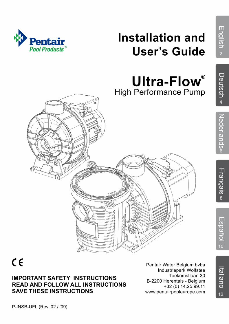
Ultra-Flow®
Installation and User’s Guide
High Performance Pump
P-INSB-UFL (Rev. 02 / ’09)
English
Deutsch
Nederlands
FrançaisE
spañolItaliano
Pentair Water Belgium bvbaIndustriepark Wolfstee
Toekomstlaan 30B-2200 Herentals - Belgium
+32 (0) 14.25.99.11www.pentairpooleurope.com
2
4
6
8
10
12
© 2008 Pentair Water Pool and Spa, Inc. All rights reserved
This document is subject to change without notice
Trademarks and disclaimers: Ultra-Flow® and Pentair Pool Products® are trademarks and/or registered trademarks of Pentair Water Pool and Spa, Inc. and/or its affiliated companies. Unless noted, names and brands of others that may be used in this document are not used to indicate an affilitation or endersement between the proprietors of these names and brands and Pentair Water Pool and Spa, Inc. Those names and brands may be the trademarks of those parties or others.
Customer Support
HERENTALS, BELGIUM (8:30 A.M. to 4:30 P.M.) CET
Phone: + 32 (0) 14 25 99 11
Website: www.pentairpooleurope.com
Declaration of Conformity
We declare, under our sole responsibility, that the product identi-fied in this declaration, and to which this declaration relates, are in conformity with the protection requirements of Council Directive 98/ 37/EEG
The manufacturer, Pentair Water Belgium N.V., has the right to modify the products without previous notice for as far as their characteristics are not really changed by this.
THESE OPERATING INSTRUCTIONS CONTAIN IMPORTANT INFOR-MATION ON THE SAFE, PROPER AND ECONOMICAL OPERATION OF THE SWIMMING POOL PUMPS. STRICT OBSERVATION OF THE OPERATING INSTRUCTIONS WILL HELP TO AVOID DANGERS, RE-DUCE REPAIR COSTS AND SHUTDOWN TIMES AND INCREASE THE RELIABILITY AND WORKING LIFE OF THE PRODUCT.
IMPORTANT SAFETY PRECAUTIONS
Section 1General informationCheck carton for any evidence of damage due to rough handling in shipment. If carton or any pump components are damaged, notify the carrier immediately.
Failure to follow the safety instructions may result in serious adverse health effects, or even serious or fatal injury. Failure to follow the safety instructions will in all cases invalidate all guarantees and liability on the part of the manufacturer.
This pump is equipped with a mechanical seal.•Avoid dry run of the pump, as long as the pump •isnotfilledwithwater;Damage to shaft seal could be the cause by non-•observance of instructions.Pleasefollowinstructionsforfillingupthepump•according to installation and instruction manual.
Section 2ApplicationOnly to be used to circulate swimming pool water.
Section 3Installation
Install the pump as near to the pool as practical.• Use a direct and short suction line with continuous • slope in order to avoid long priming times.
Eng
lish
The pump should be placed on a flat, solid foundation, • high enough to prevent flooding of the motor. Install the filter and pump in a sheltered location, ensu-• ring ventilation and adequate access for servicing.Do not mount electrical controls directly over pump.• Provide adequate floor drainage to prevent flooding. • Size all piping adequately and keep the number of el-• bows to a minimum.Independently support the pipe near the suction and • discharge of the pump in order to reduce the strain on the pump.Avoid overtightening pipe connections. Use only pipe • sealants formulated for plastics. Do not use petroleum based products. It is essential that the suction line is free of air leaks. The suction line should always be at least the same size as the suction inlet of the pump.
Please note: There can be specific needs to use pumps by swimming pools, garden ponds or such places.
Section 4Start / OperationStarting the pump
Fill pump strainer with water to suction pipe level.• Lubricate the lid O-ring with silicone each time it is re-• moved. Energize the motor, the pump will prime. The priming • time depends on the suction lift and distance to the pool. Five minutes is a reasonable time. Pump will not lift more than 2,5 meter. If pump does • not prime, see troubleshooting guide.
MaintenanceThe strainer basket should be daily removed and cleaned. Never operate the pump without its strainer basket.
Component Check / Interval Remarks
Warning pictograms Visual check / Monthly Replace if necessary
Water supply Check lines and Repair any damage connections / Monthly immediately
Safety devices Visual check / Monthly Ensure correct installation / refitting
General condition Visual check /Half-yearly Look out for any of pumps corrosion or damage
Cooling ribs of Clean the cooling ribs to electric motors maintain the cooling effect / Half-yearly
Electrical equipment Check / Monthly Rectify loose connections or singed cables immediately. Have all faults repaired by a qualified electrician
Preliminary filter Check housing for dirt / Remove all dirt housing Weekly thoroughly
O-Ring in Visual check / Half-yearlypreliminary filter cover
2
English
Winterizing
Protect the pump from freezing. • Remove all plugs and drain the pump and all piping. • Store drains and plugs in the strainer basket.• Remove the pump to a dry and warm room. • Do not wrap the motor with plastic covering as con-• densation may damage the pump. In installations where the pump can not be drained, a • 40% propylene glycol, 60% water solution will protect to -46°C. Do not use other anti-freeze solutions, these are all • highly toxic and will damage the pump.
Section 5Electrical connectionThe electrical motor must be wired by a professional ac-cording to this installation instruction and all applicable lo-cal regulations.By introduction of the pumps a motor security has to be foreseen by the installation. The security has to be tuned in to the nominal power of the motor.
Single phase
0.55kW/230V - 3.6A0.75kW/230V - 4.8A1.1kW/230V - 6.7A1.5kW/230V - 9.0A2.2kW/230V - 12.2A
Three phase
0,55kW/400V - 1.3A 0.75kW/400V - 1.75A1.1kW/400V - 2.3A1.5kW/400V - 3.3A2.2kW/400V - 4.7A
The supply voltage should be within ± 5% of the design voltage, specified on the nameplate of the motor.
Single-phase motors should be connected at the two terminals as indicated in the junction box.
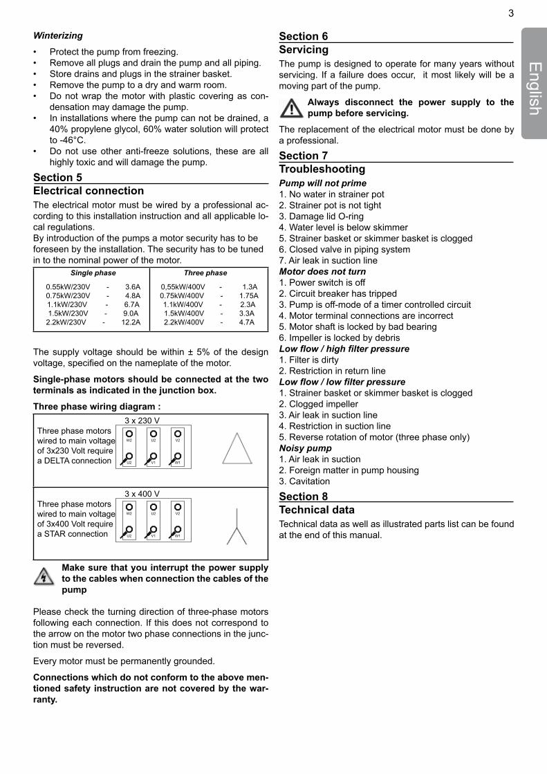
Three phase wiring diagram :
3 x 230 V Three phase motors
W2 U2 V2
U2 V1 W1
wired to main voltageof 3x230 Volt require a DELTA connection
3 x 400 VThree phase motors
W2 U2 V2
U2 V1 W1
wired to main voltage of 3x400 Volt require a STAR connection
Make sure that you interrupt the power supply to the cables when connection the cables of the pump
Please check the turning direction of three-phase motors following each connection. If this does not correspond to the arrow on the motor two phase connections in the junc-tion must be reversed.
Every motor must be permanently grounded.
Connections which do not conform to the above men-tioned safety instruction are not covered by the war-ranty.
Section 6ServicingThe pump is designed to operate for many years without servicing. If a failure does occur, it most likely will be a moving part of the pump.
Always disconnect the power supply to the pump before servicing.
The replacement of the electrical motor must be done by a professional.
Section 7TroubleshootingPump will not prime1. No water in strainer pot2. Strainer pot is not tight3. Damage lid O-ring4. Water level is below skimmer5. Strainer basket or skimmer basket is clogged6. Closed valve in piping system7. Air leak in suction lineMotor does not turn1. Power switch is off2. Circuit breaker has tripped3. Pump is off-mode of a timer controlled circuit4. Motor terminal connections are incorrect5. Motor shaft is locked by bad bearing6. Impeller is locked by debrisLow flow / high filter pressure1. Filter is dirty2. Restriction in return lineLow flow / low filter pressure1. Strainer basket or skimmer basket is clogged2. Clogged impeller3. Air leak in suction line4. Restriction in suction line5. Reverse rotation of motor (three phase only)Noisy pump1. Air leak in suction2. Foreign matter in pump housing3. Cavitation
Section 8Technical dataTechnical data as well as illustrated parts list can be found at the end of this manual.
3
Deu
tsch
Abschnitt 1 Allgemeine InformationenUberprüfen Sie den Karton auf Anzeichen von Schäden, die auf eine unsachgemässe Behandlung während des Transports zurückzuführen sind. Benachrichtingen Sie sofort die Transportgesellschaft, falls der Karton oder Pumpeteil beschädigt ist.
Das Nichtbeachten der Sicherheitshinweise kann schwere gesundheitsschädliche Aus-wirkungen zur Folge haben, bis hin zu lebensgefährlichen Verletzungen! Des Weiteren erlischt in diesem Falle jegliche Gewähr-eistung und Haf-tung des Herstellers.
Die Pumpe ist mit einer mechanischen Wellenabdichtung •ausgerüstet.Trockenlauf der Pumpe muss vermieden werden, solange die •Pumpe nicht mit Wasser aufgefüllt ist.Bei Nichtbeachtung kann die Wellendichtung trockenlaufen •und zerstört werden.Auffüll-Vorschriften sind in der Pumpenbetriebsanweisung •enthalten.
Abschnitt 2ApplicationNur zur Verwendung der Wasserzirkulation an Schwimmbecken.
Abschnitt 3Installation
Installieren Sie die Pumpe aus praktischen Gründen so nahe • möglich am Schwimmbecken.Verwenden Sie eine direkte und kurze Ansaugleitung und achten • Sie auf eine gleichmässige Neigung des Ansaugschlauchs, um so-mit lange Ansaugzeiten zu vermeiden. Die Pumpe sollte auf einem ebenen und festen Fundament be-• festigt werden, das hoch genug ist, damit der Pumpenmotor nicht durch Bodenwasser unterspült wird.
Montieren Sie die elektrischen Steuervorrichtungen nicht un mittel-• bar auf der Pumpe.Installieren Sie den Skimmerfilter und die Pumpe an einem ge-• schützten Ort und achten Sie dabei auf eine ungehinderte Belüftung und einen ungehinderte Zugang für die Wartung.Verwenden Sie Schlauchstücke mit entsprechender Länge und • entsprechendem Durchmesser und verwenden Sie nur eine Minde-stanzahl an Winkelstücken. Befestigen Sie ungeachtet dessen den Schlauch an der Ansaug-• und Auslaufstelle, um somit jegliche Zugeinwirkungen auf die Pumpe zu vermeiden. Vermeiden Sie ein Überdrehen der Anschluss-kupplungen und ver-• wenden Sie nur eine für Kunststoffe geeignete Abdichtmasse. Ver-wenden Sie keine Mittel auf Basis von Erdöl. Es ist von grundlegender Wichtigkeit, dass die Ansaugleitung frei • von jeglichen Leckstellen ist. Der Ansaugschlauch sollte minde-stens den gleichen Durchmesser wie der Ansaugstutzen der Pumpe aufweisen.
Hinweis: Es können besondere Anforderungen bestehen für Pumpen zur Verwendung an Schimmbecken, Gartenteiche oder ähnliche Orte.
Abschnitt 4Start / InbetriebnahmeInbetriebnahme und Saugbetrieb
Füllen Sie vor der Inbetriebnahme der Pumpe den Vorfilter bis auf • die Höhe des Ansaugstutzens mit Wasser auf. Schmieren Sie den Dichtungsring des Deckels bei jedem Abneh-• men des Deckels mit einer Silikonpaste ein. Schalten Sie den Motor an, die Pumpe fängt an zu saugen. Die • Ansaugdauer hängt von der Ansaughöhe und der Entfernung zu dem Schimmbecken ab. Dabei sind fünf Minuten eine ange-messene Dauer. Die Ansaughöhe beträgt höchstens 2,5 M. Beziehen Sie sich auf die • Fehlerermittlungstabelle, falls keine Ansaugung erfolgt.
Wartung und InstandhaltungDer Filterkorb sollte täglich herausgenommen und gründlich gereinigt werden. Nehmen Sie die Pumpe grundsätzlich nicht ohne eingesetzten Filterkorb in Betrieb.
Bauteil Kontrolle / Zeitspanne Bemerkung
Warn-Piktogramm Sichtprüfung / monatlich Erforderlichenfalls ersetzen
Medienversorgung Dichtheitsprüfung Beschädigungen (Wasser) der Leitungen umgehend und Anschlüsse / monatlich beseitigen
Schutzeinrich- Sichtprüfung / monatlich Auf Montage/ tungenn Remontage ist zu achten
Allgemeiner Zustand Sichtprüfung / halbjährlich Achten Sie auf der Schwimmbad- Korrosion, Schädenpumpen und Mängel
Kühlrippen der Reinigen der Kühl- E-Motoren rippen, da sonst die Kühlwirkung beeinträchtigt ist / halbjährlich
Elektrische Kontrollieren / Lose Verbindungen Ausrüstung monatlich bzw. Angeschmorte Kabel müssen sofort beseitigt werden. Mangel- behebung durch Elektrofach- betrieb durchführen lassen
Vorfilterkorb Korb auf Alle Verschmutzung Verschmutzungen kontrollieren / gründlich entfernen wöchentlich
O-Ring im Vorfilter- Sichtprüfung / deckel halbjährlich
Kundendienst
HERENTALS, BELGIEN (8:30 Uhr bis 16:30 Uhr) MEZ
Telefon: + 32 (0) 14 25 99 11
Internet: www.pentairpooleurope.com
© 2008 Pentair Water Pool and Spa, Inc. Alle Rechte vorbehalten.
Änderungen der Anleitung vorbehalten.
Marken und Haftungsausschluss: Ultra-Flow™ und Pentair Pool Products™ sind Markennamen und/oder eingetragene Warenzeichen der Pentair Water Pool and Spa, Inc. und oder ihrer Tochterfirmen. Sofern nicht anders erwähnt, dient die Nennung von Namen oder Markenzeichen anderer Firmen in diesem Dokument nicht dem Zweck, eine Partnerschaft oder Vereinbarung zwischen den Eigentümern dieser Namen oder Marken und der Pentair Water Pool and Spa, Inc zu signalisieren. Diese Namen und Marken können Warenzeichen oder eingetragene Markennamen dieser Firmen oder anderer sein.
KonformitätserklärungWir erklären unter unserer alleinigen Verantwortung, dass das in dieser Erklärung genannte Produkt, auf das sich diese Erklärung bezieht, den Schutzanforderungen der Richtlinie 98/37/EWG entspricht.
Der Hersteller, Pentair Water Belgium N.V., hat das Recht die Produkte ohne vorangehende Benachrichtung zu ändern soweit deren Eigneschaften hierdurch nicht wesentlich geändert werden.
WICHTIGE SICHERHEITSHINWEISE
DIE BETRIEBSANLEITUNG ENTHÄLT WICHTIGE HINWEISE, UM DIE SCHWIMMBADPUMPEN SICHER, SACHGERECHT UND WIRTSCHAFTLICH ZU BETREIBEN. IHRE BEACHTUNG HILFT GEFAHREN ZU VERMEIDEN, REPARATURKOSTEN UND AUSFAL-LZEITEN ZU VERMINDERN UND DIE ZUVER-LÄSSIGKETI UND LEBENSDAUER DER SCHWIMMBADPUMPEN ZU ERHÖHEN.
4
Deutsch
WinterlagerungSchützen Sie die pumpe vor Frost. • Nehmen Sie alle Stopfen und Schläuche ab und lassen Sie sämtli-• ches Wasser ablaufen. Bewahren Sie die Stopfen in dem Filterkorb auf. • Lagern Sie die Pumpe in der kalten Jahreszeit in einem trockenen • und warmen Raum. Decken Sie die Pumpe nicht mit einer Kunststofffolie ab, um eine für • die Pumpe schädliche Kondensation zu vermeiden.Wenn die Pumpe ortsfest montiert und das Wasser nicht abgelas-• sen werden kann, bietet eine aus 40% Propylenalkohol und 60% Wasser bestehende Lösung einen Frostschutz bis -46°C. Verwenden Sie keine anderen Frostschutzmittel als Polypropylen-• glykol, da andere Frostschutzmittel hochgiftig sind und die Pumpe nachhaltig beschädigen können.
Abschnitt 5Elektrische AnschlüsseDer Elektromotor muss von einem Fachmann unter Beachtung dieser Einbauanleitung und aller lokal geltenden Bestimmungen und Vorschrif-ten verkabelt werden.Bei der inbetriebnahme der pumpen ist in der Installation ein mo-torschutzschalter vorzusehen, der auf die nenndaten des motors eingestellt ist.
Einphasiges0.55kW/230V - 3.6A0.75kW/230V - 4.8A1.1kW/230V - 6.7A1.5kW/230V - 9.0A2.2kW/230V - 12.2A
Dreiphasig0,55kW/400V - 1.3A 0.75kW/400V - 1.75A1.1kW/400V - 2.3A1.5kW/400V - 3.3A 2.2kW/400V - 4.7A
Die Speisespannung muss mit der Spannung auf dem Typenschild übe-reinstimmen - zugelassene Toleranz: ± 5%.
Bei Einphasenmotoren muss die Verdrahtung über die zwei in der Anschlussdose entsprechend gekennzeichneten Anschlussklem-men erfolgen.
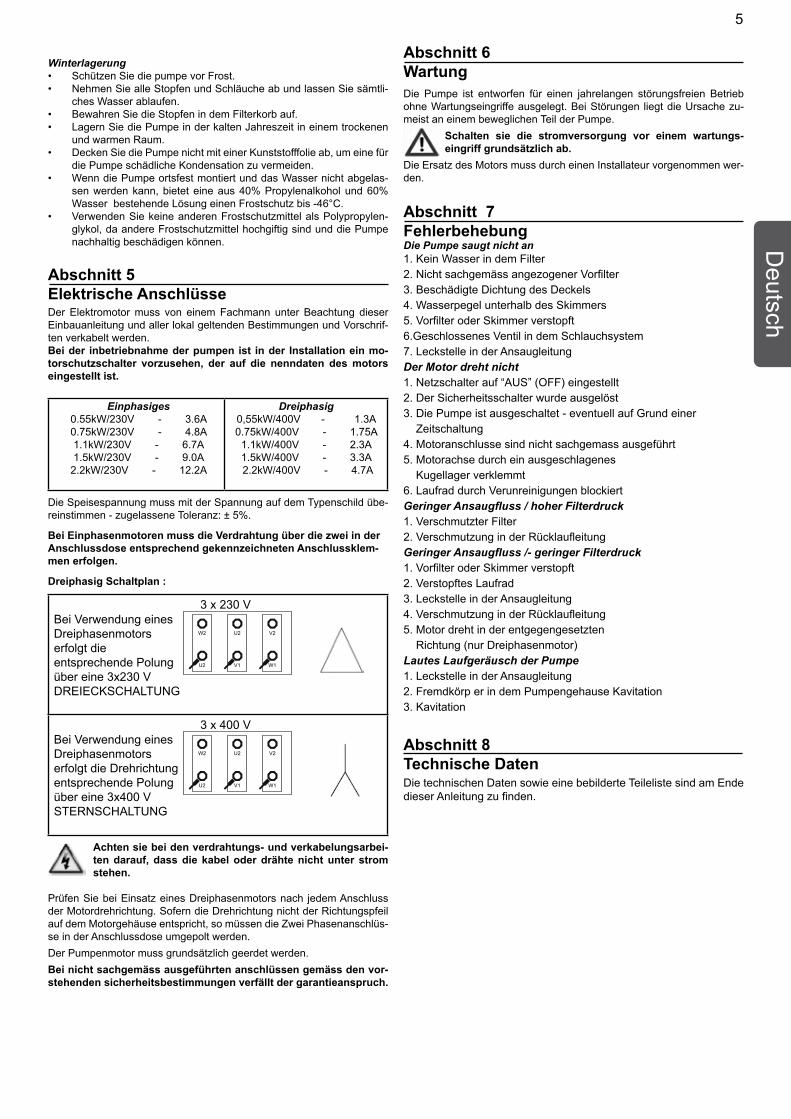
Dreiphasig Schaltplan :
3 x 230 V Bei Verwendung eines
W2 U2 V2
U2 V1 W1
Dreiphasenmotors erfolgt die entsprechende Polungüber eine 3x230 V DREIECKSCHALTUNG
3 x 400 VBei Verwendung eines
W2 U2 V2
U2 V1 W1
Dreiphasenmotors erfolgt die Drehrichtung entsprechende Polung über eine 3x400 V STERNSCHALTUNG
Achten sie bei den verdrahtungs- und verkabelungsarbei-ten darauf, dass die kabel oder drähte nicht unter strom stehen.
Prüfen Sie bei Einsatz eines Dreiphasenmotors nach jedem Anschluss der Motordrehrichtung. Sofern die Drehrichtung nicht der Richtungspfeil auf dem Motorgehäuse entspricht, so müssen die Zwei Phasenanschlüs-se in der Anschlussdose umgepolt werden.Der Pumpenmotor muss grundsätzlich geerdet werden.Bei nicht sachgemäss ausgeführten anschlüssen gemäss den vor-stehenden sicherheitsbestimmungen verfällt der garantieanspruch.
Abschnitt 6WartungDie Pumpe ist entworfen für einen jahrelangen störungsfreien Betrieb ohne Wartungseingriffe ausgelegt. Bei Störungen liegt die Ursache zu-meist an einem beweglichen Teil der Pumpe.
Schalten sie die stromversorgung vor einem wartungs-eingriff grundsätzlich ab.
Die Ersatz des Motors muss durch einen Installateur vorgenommen wer-den.
Abschnitt 7FehlerbehebungDie Pumpe saugt nicht an1. Kein Wasser in dem Filter2. Nicht sachgemäss angezogener Vorfilter3. Beschädigte Dichtung des Deckels4. Wasserpegel unterhalb des Skimmers5. Vorfilter oder Skimmer verstopft6.Geschlossenes Ventil in dem Schlauchsystem7. Leckstelle in der AnsaugleitungDer Motor dreht nicht1. Netzschalter auf “AUS” (OFF) eingestellt2. Der Sicherheitsschalter wurde ausgelöst3. Die Pumpe ist ausgeschaltet - eventuell auf Grund einer Zeitschaltung4. Motoranschlusse sind nicht sachgemass ausgeführt5. Motorachse durch ein ausgeschlagenes Kugellager verklemmt6. Laufrad durch Verunreinigungen blockiertGeringer Ansaugfluss / hoher Filterdruck1. Verschmutzter Filter2. Verschmutzung in der RücklaufleitungGeringer Ansaugfluss /- geringer Filterdruck1. Vorfilter oder Skimmer verstopft2. Verstopftes Laufrad3. Leckstelle in der Ansaugleitung4. Verschmutzung in der Rücklaufleitung5. Motor dreht in der entgegengesetzten Richtung (nur Dreiphasenmotor)Lautes Laufgeräusch der Pumpe1. Leckstelle in der Ansaugleitung2. Fremdkörp er in dem Pumpengehause Kavitation3. Kavitation
Abschnitt 8Technische DatenDie technischen Daten sowie eine bebilderte Teileliste sind am Ende dieser Anleitung zu finden.
5
Ned
erla
nds
Sectie 3Installatie
Installeer de pomp zo dicht mogelijk bij het waterbekken.• Gebruik een zo recht en kort mogelijke zuigleiding met een • constante helling, zo vermijdt u lange ontluchtingstijden. De pomp moet op een vlakke, stevige fundering gemon-• teerd worden die hoog genoeg is zodat de motor niet onder water kan komen te staan. Monteer de elektrische bedieningsschakelaar niet op de • pomp.Installeer de filter en de pomp op een beschutte, goed ge-• ventileerde plaats die goed toegankelijk is voor onderhoud. Dimensioneer alle leidingen correct en beperk het aantal • bochten tot een minimum. Ondersteun de leidingen van en naar de pomp om de be-• lasting op de pomp tot een minimum te beperken. Span de pijpverbindingen niet te hard aan en gebruik alleen • speciale kleefmiddelen die geschikt zijn voor kunststof. Ver-mijd producten op basis van minerale olie. Het is belangrijk dat de aanzuigleiding vrij is van luchtlekken. De diameter van de aanzuigleiding moet altijd tenminste even groot zijn als de zuigopening van de pomp.
Opgelet: Er kunnen bijzondere vereisten zijn bij het gebruik van pompen aan zwembaden, tuinvijvers of soortgelijke plaatsen.
Sectie 4Opstarten / WerkingStarten en ontluchten
Vooraleer de pomp te starten, moet het pomphuis met water • gevuld worden tot op het niveau van de aanzuigleiding.Telkens u het deksel verwijderd heeft, moet u de O-ring op-• nieuw met silicone insmeren. Start de motor. De pomp begint aan te zuigen. De ontluch-• tingstijd is afhankelijk van de aanzuighoogte en de afstand tot het zwembad. Vijf minuten is normaal. De pomp kan een maximaal hoogteverschil van 2,5 meter • overwinnen. Als de pomp niet aanzuigt, raadpleeg dan het hoofdstuk ‘Problemen oplossen’.
OnderhoudDe filterkorf moet dagelijks verwijderd en gereinigd worden . Zet de pomp nooit in werking zonder de korf.
Component Controle / Interval Opmerkingen
Waarschuwings- Visuele controle/Maandelijks Vervang indien pictogrammen nodig
Watertoevoer Controleer leidingen Herstel alle schade en aansluitingen/Maandelijks onmiddellijk
Veiligheids- Visuele controle/Maandelijks Zorg voor correcte installaties installatie /herstel
Algemene staat Visuele controle/Halfjaarlijks Let op van de pompen roestvorming of schade
Koelribben van Reinig de koelribben elektromotoren om de koelende werking te behouden/HalfjaarlijksElektrische Controle / Maandelijks Rectificeer losse uitrusting aansluitingen of geschroeide kabels onmiddellijk. Laat alle fouten direct door een bekwame elektricien herstellen.
Behuizing van Controleer de Verwijder al het vuil prefilter behuizing op vuil / Wekelijks grondig
O-Ring in deksel Visuele controle / Halfjaarlijks van voorfilter
Sectie 1 Algemene informatieControleer bij ontvangst de pomp op eventuele transportschade. Verwittig bij beschadiging onmiddellijk de transporteur.
Het niet opvolgen van de veiligheidsinstructies kan tot ernstige gezondheids-problemen, zelfs ernstig of dodelijk letsel leiden. Het niet opvolgen van de vei-ligheidsinstructies zal in elk geval alle garanties en aansprakelijkheden van de fabrikant nietig maken.
Deze pomp is voorzien van een mechanische dichting.•Vermijdt het droogdraaien van de pomp, zolang de •pomp niet met water gevuld is.Schade aan de mechanische dichting kan het gevolg •zijn van het niet-naleving van de instructies.Gelieve de instructies te volgen voor het opvullen van •de pomp, volgens de installatie en instructiehandlei-ding.
Sectie 2ToepassingEnkel gebruiken voor circulatie van zwembadwater.
BELANGRIJKE VEILIGHEIDSVOORZORGEN
© 2008 Pentair Water Pool and Spa, Inc. Alle rechten voorbehouden
Dit document kan worden gewijzigd zonder kennisgeving
Handelsmerken en disclaimers: Ultra-Flow™ en Pentair Pool Products™ zijn handelsmerken en/of gedeponeerde handelsmerken van Pentair Water Pool and Spa, Inc. en/of hieraan gelieerde bedrijven. Tenzij anders aangegeven, vormen de namen en merken van anderen die mogelijk in dit document worden gebruikt geen aanwijzing voor samenwerking of wederzijdse goedkeuring tussen de eigenaren van deze namen en merken en Pentair Water Pool and Spa, Inc. Deze namen en merken zijn mogelijk de handelsmerken of gedeponeerde handelsmerken van deze partijen of anderen.
Klantendienst
HERENTALS, BELGIUM (8.30 uur tot 16.30 uur) CET
Telefoon: + 32 (0) 14 25 99 11
Website: www.pentairpooleurope.com
Conformiteitsverklaring
We verklaren, op eigen verantwoordelijkheid, dat het product dat beschreven wordt in dit document en waarop deze informatie betrekking heeft, overeenstemt met de vereisten van de Richtlijn van de Raad 98/37/EEG
De fabrikant, Pentair Water Belgium N.V., heeft het recht om de producten te wijzigen zonder vooraf-gaande melding, voor zover hun eigenschappen hierdoor niet wezenlijk veranderd worden.
DEZE HANDLEIDING BEVAT BELANGRIJKE INFORMATIE OVER HET VEILIGE, JUISTE EN ZUINIGE GEBUIK VAN ZWEMBADPOM-PEN. HET NAUWGEZET OPVOLGEN VAN DE INSTRUCTIES ZAL GEVAARLIJKE SITUATIES HELPEN VOORKOMEN, REPARATIE-KOSTEN EN BUITEN BEDRIJF PERIODES HELPEN VERMINDE-REN EN DE BETROUWBAARHEID EN LEVENSDUUR VAN HET PRODUCT VERHOGEN.
6
Nederlands
OverwinterenBescherm de pomp tegen de vrieskou. • Verwijder alle pluggen en laat de pomp en alle leidingen • leeglopen. Bewaar de pluggen in de korf. • Berg de pomp in een droge en warme kamer op.• Wikkel de motor niet in plastic omdat er dan binnenin con-• densatie kan ontstaan. In installaties waar de pomp niet geledigd kan worden, be-• schermt een mengsel van 40% propyleenglycol en 60% wa-ter de pomp tot temperaturen van -46°C. Gebruik uitsluitend propyleenglycol. Andere antivries-midde-• len zijn uiterst giftig en beschadigen de pomp.
Sectie 5Elektrische aansluitingDe elektrische aansluiting van de motor moet door aan vakman gedaan worden in overeenstemming met deze handleiding en lokale regelgeving.
Bij de ingebruikname van de pomp moet bij de installatie een motorbeveiliging voorzien worden, die afgestemd is op de nominale stroom van de motor.
Enkelfasig0.55kW/230V - 3.6A0.75kW/230V - 4.8A1.1kW/230V - 6.7A1.5kW/230V - 9.0A2.2kW/230V - 12.2A
Driefasig0,55kW/400V - 1.3A 0.75kW/400V - 1.75A1.1kW/400V - 2.3A1.5kW/400V - 3.3A 2.2kW/400V - 4.7A
De voedingsspanning moet voor ± 5% overeenkomen met deze die vermeld staat op de kenplaat van de motor. Bij enkelfasige motoren dient de aansluiting te gebeuren op de twee aangeduide klemmen in de aansluitdoos.
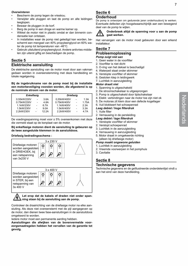
Driefasig bedradingsschema :
3 x 230 V Driefasige motoren
W2 U2 V2
U2 V1 W1
worden aangesloten in DRIEHOEK, bij een netspanning van 3x230 V
3 x 400 VDriefasige motoren
W2 U2 V2
U2 V1 W1
worden aangesloten in STER, bij een netspanning van 3x 400 V
Let erop dat de kabels of draden niet onder span-ning staan bij de aansluiting aan de pomp.
Controleer de draairichting van de driefasige motor na elke aan-sluiting. Als deze niet overeenstemt met de pijl aangegeven op de motor, dan dienen twee fase-aansluitingen in de aansluitdoos omgekeerd te worden.Iedere motor moet een permanente aarding hebben.Aansluitingen die afwijken van de bovenvermelde voor-zorgsmaatregelen hebben het vervallen van de garantie tot gevolg.
Sectie 6OnderhoudDe pomp is ontworpen om gedurende jaren onderhoudsvrij te werken. Eventuele defecten zijn hoogstwaarschijnlijk aan een bewegend deel van de pomp te wijten.
Onderbreek altijd de spanning voor u aan de pomp gaat werken.
Het vervangen van de motor moet gebeuren door een erkend installateur.
Sectie 7ProbleemoplossingPomp zuigt niet aan1. Geen water in de voorfilter2. Voorfilter is niet dicht3. O-ring van het deksel is beschadigd4. Waterpeil staat onder skimmer5. Verstopte voorfilter of skimmer6. Gesloten klep in leidingwerk7. Luchtlek in aanzuigleidingMotor draait niet1. Spanning is uitgeschakeld2. De stroomschakelaar is uitgesprongen3. Pomp is uitgeschakeld door tijdschakelaar4. Elektr. verbindingen naar de motor toe zijn niet ok5. De motoras zit klem door een defecte kogellager6. Vuil blokkeert het schoepenradLaag debiet / hoge filterdruk1. Vuile filter2. Vernauwing in de persleidingLaag debiet / lage filterdruk1. Verstopte voorfilter of skimmer2. Verstopt schoepenrad3. Luchtlek in de aanzuigleiding4. Vernauwing in aanzuigleiding5. Motor draait in omgekeerde richting (alleen bij driefasige motor)Pomp maakt ongewone geluiden1. Luchtlek in aanzuigleiding2. Vreemde voorwerpen in het pomphuis3. Cavitatie
Sectie 8Technische gegevensTechnische gegevens en de geïllustreerde onderdelenlijst vindt u aan het eind van deze handleiding.
7
MESURES IMPORTANTES DE SÉCURITÉ
Fran
çais
LA NOTICE D’EMPLOI CONTIENT DES INFORMATIONS IMPOR-TANTES PERMETTANT D’UTILISER LES POMPES DE PISCINE DE MANIERE SURE, CORRECTE ET ECONOMIQUE. OBSERVER CETTE NOTICE D’EMPLOI AIDE A PREVENIR DES DANGERS, REDUIRE LES FRAIS DE REPARATION ET LES PERIODES DE DEFAILLANCES ET A AUGMENTER LA DUREE DE VIE DES POM-PES DE PISCINE.
Section 1 Information généralesContrôlez la pompe à la réception pour déterminer les pertes et dégâts éventuels dûs au transport. En cas de dégât, avertissez immédiatement le transporteur.
La non observation des instructions de sécurité peut avoir des répercussions dangereuses pour la santé, voire même causer des blessures pouvant mettre la vie en danger. En outre, toute garantie et responsabi-lité du fabricant perd son effet dans ce cas.
Cette pompe est équipée d’un presse-étoupe mécani-•que.Il faut éviter de faire tourner la pompe à sec, c’est-à-dire •sansqu’ellesoitremplied’eau;ilfautdoncl’amorcerpour la première mise en route.Eneffet,lepresse-étoupeestlubrifiéparl’eau,unfunc-•tionnement à sec le détériorait.Pour de plus amples renseignements, se référer à la no-•tice d’installation et d’entretien concernant la pompe.
Section 2ApplicationUtiliser uniquement à circuler l’eau de piscines.
Section 3Installation
Installer la pompe le plus près possible du bassin. • Utiliser un tuyau d’aspiration direct et court à pente constante •
en vue d’éviter de long temps d’amorçage. La pompe doit être fixée sur un socle plat et solide, suffisam-• ment haut pour éviter de noyer le moteur.Installer le filtre et la pompe dans un endroit protégé en • s’assurant que la ventilation et l’accès pour la maintenance sont appropriés. Ne pas installer les dispositifs de réglage directement au-des-• sus de la pompe. Veiller à un drainage suffisant du sol pour éviter d’exposer la • pompe à l’eau. Préparer tous les tuyaux aux bonnes dimensions et réduire au-• tant que possible le nombre de coudes. • Prévoir un support indépendant pour le tuyau à proximité de • l’aspiration et du refoulement de la pompe en vue de réduire l’effort de la pompe. Eviter un serrage excessif des jonctions de tuyaux. N’utiliser • pour le tuyaux que des matériaux d’étanchéité prévus pour ma-tieres plastiques. Eviter les produits à base de pétrole. Il est es-sentiel que le tuyau d’aspiration ne présente aucune prise d’air. Son diamètre doit toujours au moins être égal à celui de l’orifice de’aspiration de la pompe.
Attention : Il peut y avoir des besoins spécifiques pour employer des pompes dans des piscines, des étangs de jardins ou de pareils endroits.
Section 4Démarrage / UtilisationInstructions de démarrage et d’amorçage
Avant de démarrer la pompe, remplir le préfiltre avec l’eau jusqu’au • niveau de la conduite d’aspiration. Lubrifier le joint torique du couvercle avec de la graisse silicone • chaque fois qu’il est enlevé.Enclencher le moteur, la pompe s’amorce. Le temps d’amorçage • dépend de la hauteur d’aspiration et de la distance séparant la pompe du bassin. Cinq minutes constituent un temps raisonable. La pompe ne peut pas aspirer l’eau à une hauteur de plus de • 2,5 mètres. Si la pompe ne s’amorce pas, consulter le guide de dépistage des défauts.
MaintenanceLe panier du préfiltre doit être enlevé et nettoyé chaque jour. Ne jamais faire fonctionner la pompe sans panier.Composant Contrôle/Interval RemarquePictogramme Contrôle visuel / Remplacer en cas de d’avertissement 1 fois par mois besoinAlimentation en Contrôle d’étanchéité Réparer les media (eau) des conduits et des dommages connexions/1 fois par mois immédiatementDispositifs de Contrôle visuel /1 fois par Veiller au montage / protection mois remontageÉtat général des Contrôle visuel / tous les Faites attention à la pompes de piscine 6 mois corrosion, aux dommages et aux défautsAilettes de Nettoyage des ailettes de refroidissement refroidissement; sinon, des moteurs l’effet de refroidissement électriques en est altéré / tous les 6 moisÉquipement Contrôler /1 fois par mois Les connexions électrique lâches ou les câbles grillés doivent être enlevés immédiatement. Veuillez laisser du personnel spécialisé en électricité procéder à ces réparationsPanier du préfiltre Contrôler la Enlever totalement propreté du panier /1 fois les souilleurs par semaineAnneau torique Contrôle visuel /1 fois par d’étanchéité du 6 mois couvercle du préfiltre
© 2008 Pentair Water Pool and Spa, Inc. Tous droits réservés
Cedocumentestsujetàmodificationsanspréavis
Marques et clauses d'exclusion de responsabilité : Ultra-Flow™ et Pentair Pool Products™ sont des marques de Pentair Water Pool and Spa, Inc. et/ou de ses sociétés affiliées. Sauf indication contraire, les noms et marques de tiers pouvant être utilisés dans ce document ne sont pas utilisés pour indiquer une affiliation ou une acceptation entre les propriétaires de ces noms ou marques et Pentair Water Pool and Spa, Inc. Ces noms ou marques peuvent êtres des marques déposées ou commerciales de tiers.
Service clientèle
HERENTALS, BELGIQUE (8h30 à 16h30) HNEC
Téléphone : + 32 (0) 14 25 99 11
Site web : www.pentairpooleurope.com
Déclaration de conformitéNous déclarons, sous notre seule responsabilité, que le produit identifié dans cette déclaration, et concerné par cette déclaration, est en conformité avec les exigences de la Council Directive 98/37/EEG
Le fabricant, Pentair Water Belgium N.V., a le droit de modifier les produits sans avis préalable, dans la mesure où cela ne change pas essentiellement leurs caractéristiques
8
FrançaisHivernage
Protéger la pompe contre le gel. • Enlever tous les bouchons de vidange et désamorcer la • pompe et vider tous les tubes. Stocker les drains et les bouchons dans le panier de la pom-• pe. Transporter la pompe dans un local sec et chaud. • Ne pas recouvrir le moteur d’une enveloppe plastique, car • une condensation peut se former à l’intérieur.Au cas où la pompe ne peut pas être vidangée, un mélan-• ge de 40% de propylène glycol et de 60% d’eau protègera l’appareil jusqu’à -46°C. Ne pas utiliser d’autres antigels que le propylène glycol: ils • sont en effet extrêmement toxiques et endommageraient la pompe.
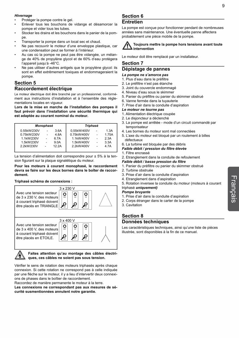
Section 5Raccordement électriqueLe moteur électrique doit être branché par un professionnel, conformé-ment aux instructions d’installation et à l’ensemble des régle-mentations locales en vigueur.Lors de la mise en marche de l’installation des pompes il faut prévoir dans l’installation une sécurité thermique qui est adaptée au courant nominal du moteur.
Monophasé0.55kW/230V - 3.6A0.75kW/230V - 4.8A1.1kW/230V - 6.7A1.5kW/230V - 9.0A2.2kW/230V - 12.2A
Triphasé0,55kW/400V - 1.3A 0.75kW/400V - 1.75A1.1kW/400V - 2.3A1.5kW/400V - 3.3A2.2kW/400V - 4.7A
La tension d’alimentation doit correspondre pour ± 5% à la ten-sion figurant sur la plaque signalétique du moteur. Pour les moteurs à courant monophasé, le raccordement devra se faire sur les deux bornes dans le boîter de raccor-dement.
Triphasé schéma de connexions :
3 x 230 V Avec une tension secteur
W2 U2 V2
U2 V1 W1
de 3 x 230 V, des moteursà courant triphasé doivent être placés en TRIANGLE
3 x 400 VAvec une tension secteur
W2 U2 V2
U2 V1 W1
de 3 x 400 V, des moteursà courant triphasé doiventêtre placés en ETOILE.
Faites attention qu’au montage des câbles électri-ques, ces câbles ne soient pas sous tension.
Vérifier le sens de rotation des moteurs triphasés après chaque connexion. Si cette rotation ne correspond pas à celle indiquée par une flèche sur le moteur, il y a lieu d’intervertir deux connexi-ons de phases dans le boîtier de raccordement.Raccordez de manière permanente le moteur à la terre.Les connexions ne correspondant pas aux mesures de sé-curité susmentionnées annulent notre garantie.
Section 6EntretienLa pompe est conçue pour fonctionner pendant de nombreuses années sans maintenance. Une éventuelle panne affectera probablement une pièce mobile de la pompe.
Toujours mettre la pompe hors tensions avant toute intervention
Le moteur doit être remplacé par un installateur.
Section 7Dépistage de pannesLa pompe ne s’amorce pas1. Plus d’eau dans le préfiltre2. Le préfiltre n’est pas étanche3. Joint du couvercle endommagé4. Niveau d’eau sous le skimmer5. Panier du préfiltre ou panier du skimmer obstrué6. Vanne fermée dans la tuyauterie7. Prise d’air dans la conduite d’aspirationLe moteur ne tourne pas1. Alimentation électrique coupée2. Le disjoncteur a déclenché3. La pompe est arrêtée - mode d’un circuit commandé par temporisateur4. Les bornes du moteur sont mal connectées5. L’axe du moteur est bloqué par un roulement à billes défectueux6. La turbine est bloquée par des débrisFaible débit / pression du filtre élevée1. Filtre encrassé2. Etranglement dans la conduite de refoulementFaible débit / basse pression du filtre1. Panier du préfiltre ou panier du skimmer obstrué2. Turbine obstruée3. Prise d’air dans la conduite d’aspiration4. Etranglement dans d’aspiration5. Rotation inversee la conduite du moteur (moteurs à courant triphasé uniquement)Pompe bruyante1. Prise d’air dans la conduite d’aspiration2. Corps étranger dans le carter de la pompe3. Cavitation
Section 8Données techniquesLes caractéristiques techniques, ainsi qu’une liste de pièces illustrée, sont disponibles à la fin de ce manuel.
9
Esp
añol
Sección 1 Descripción generalAl recibo de la bomba, asegúrese de que no ha sufrido daños en el transporte. Comunique de inmediato cualquier daño al trans-portista.
El incumplimiento de las instrucciones de seguridad puede ocasionar graves efectos adversos para la sa-lud, o incluso lesiones graves o mortales. En todos los casos el incumplimiento de las instrucciones de seguridad invalidará toda garantía y responsabilidad del fabricante respecto del componente.
Esta bomba va equipada con un prensaestopas meca-•nico.Evitar que funcione en seco, llenarla de aqua antes de •arrancarla.Por tanto hace falta encebarla en la primera puesta en •machayaqueelprensaestopasselubrificaconeiaqua, un funcionamiento en seco la podria deteriorar.Para una mas amplia informacion consultar el Manual •de Instalacion y mantenimiento de la bomba.
Sección 2AplicacionesLa aplicación de la bomba es la circulación de agua en piscinas.
Sección 3Instalación
Instale la bomba lo más cerca posible de la piscina.• Utilice una tubería de aspiración directa y corta, con una • pendiente uniforme, para que el tiempo de cebado no sea muy largo.
Asegure la bomba a una obra de fundación plana y firme, • con la altura apropiada para impedir la inundación del mo-tor. Instale el filtro y la bomba en un lugar protegido, con buena • ventilación y fácil acceso para su mantenimiento.No monte ningún control eléctrico directamente sobre la • bomba.Utilice los tubos con el diámetro apropiado e intente utilizar • el número mínimo de codos. Realice soportes independientes para la tubería próxima las • bocas de aspiración y descarga. Esto impedirá esfuerzos adicionales de la bomba. No apriete demasiado las uniones de las tuberías. Utilice • únicamente los selladores. indicados para tubos de plástico. No utilice productos derivados del petróleo. La línea de as-piración no ha de tener ninguna entrada de aire. Utilizar en esta línea un conducto por lo menos del tamaño de la boca de aspiración de la bomba.
Atención: tenga en cuenta que pueden haber necesidades es-pecíficas para tener que utilizar bombas en las piscinas, estan-ques del jardín y lugares parecidos.
Sección 4Puesta en marcha / FuncionamientoPuesta en marcha y cebado
Antes de poner en marcha la bomba, llene el prefiltro con • agua hasta el nivel del tubo de aspiración.Lubrifique la junta tórica de la tapa con silicona cada vez • que la abra. Conecte el motor para cebar la bomba. • El tiempo de cebado depende de la altura de aspiración y • de la distancia a la piscina. Una duración de cinco minutos es razonable. La bomba no aspirará agua en una altura superior a 2,5 • metros. Si no se hace el cebado de la bomba, consulte las indicaciones que damos para solucionar averías.
MantenimientoRetirar y limpiar cada día la cesta del prefiltro. La bomba nunca ha de funcionar sin esta cesta.
Component Check / Interval RemarksPictogramas de Comprobación visual / Cambiar si es advertencia Mensual necesarioSuministro de agua Comprobación conductos Reparar cualquier y conexiones / Mensual daño inmediatamenteDispositivos de Comprobación visual / Asegurar instalación seguridad Mensual correcta / reajusteEstado general de Comprobación visual / Comprobar que las bombas Semestral haya corrosión ni dañosAletas de Limpiar las aletas de refrigeración refrigeración para de motores mantener el efecto refrigerante eléctricos / SemestralEquipo eléctrico Comprobación / Mensual Reparar inmediata-
mente las conexi-ones sueltas o los cables quemados. Todas las reparacio-nes deben confi-arse a un electricista cualificado
Bastidor del filtro Comprobar que el Eliminar a fondo toda preliminar bastidor esté limpio /Semanal suciedadJunta tórica de la Comprobación visual cubierta del filtro preliminar /Semestral
PRECAUCIONES IMPORTANTES DE SEGURIDAD
© 2008 Pentair Water Pool and Spa, Inc. Todos los derechos reservados
Este documento está sujeto a cambios sin previo aviso
Marcas registradas y exención de responsabilidad: Ultra-Flow™ y el logotipo de Pentair Water Pool Products™ son marcas registradas de Pentair Water Pool and Spa, Inc. El resto de marcas y nombres comerciales que pueden figurar en este documento se refieren a las entidades propietarias de las marcas o sus productos. Pentair Water Pool and Spa, Inc. niega cualquier tipo de interés sobre dichas marcas y nombres de terceros.
Asistencia al cliente
HERENTALS, BÉLGICA (8:30 - 16:30)
Teléfono: + 32 (0) 14 25 99 11
Sitio web: www.pentairpooleurope.com
Declaración de conformidadDeclaramos, bajo nuestra única responsabilidad, que el producto men-cionado en esta declaración, al que la misma se refiere, cumple con los requisitos de protección de la Directiva del Consejo Europeo 98/37/EEG
El fabricante, Pentair Water Belgium N.V., tiene el derecho de modificar los productos sin previo aviso, mientras no cambien realmente sus características.
ESTAS INSTRUCCIONES CONTIENEN INFORMACIÓN IMPOR-TANTE SOBRE EL FUNCIONAMIENTO SEGURO, CORRECTO Y ECONÓMICO DE LAS BOMBAS PARA PISCINAS. LA ESTRICTA OBSERVACIÓN DE LAS INSTRUCCIONES DE FUNCIONAMIENTO CONTRIBUIRÁ A EVITAR PELIGROS, REDUCIR LOS COSTOS DE REPARACIÓN Y LOS TIEMPOS DE DESCONEXIÓN Y AUMENTAR LA FIABILIDAD Y LA VIDA ÚTIL DEL PRODUCTO
10
Protección durante el inviernoProteja la bomba contra las heladas. • Quite los tapones y deje escapar todo el líquido de la bomba • y de los conductos (conserve los tapones dentro de la cesta del prefiltro). Desmonte la bomba y téngala en un lugar seco y con cale-• facción durante el invierno. No envuelva el motor con un plástico porque podría formar-• se condensación en el interior. Con instalaciones donde no es posible purgar la bomba, pu-• ede llenarla con una mezcla de 40% de glicol de propileno y 60% de agua, lo que ofrece una protección hasta -46°C. No utilice ningún otro líquido anticongelante diferente del gli-• col de propileno. Son muy tóxicos y dañarían la bomba.
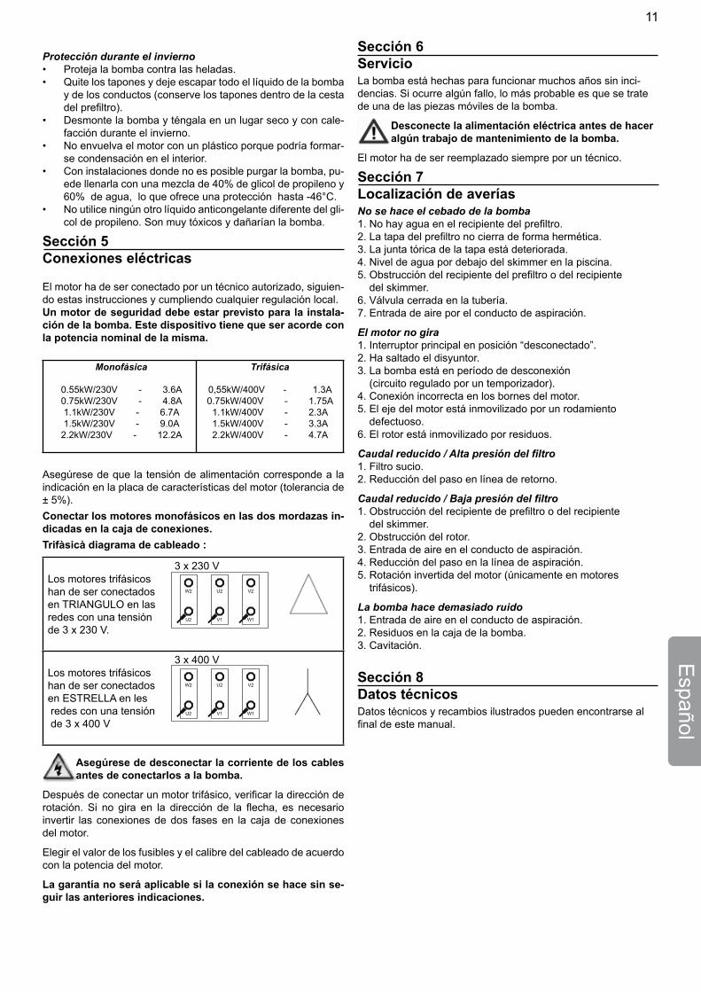
Sección 5Conexiones eléctricas
El motor ha de ser conectado por un técnico autorizado, siguien-do estas instrucciones y cumpliendo cualquier regulación local.Un motor de seguridad debe estar previsto para la instala-ción de la bomba. Este dispositivo tiene que ser acorde con la potencia nominal de la misma.
Monofásica
0.55kW/230V - 3.6A0.75kW/230V - 4.8A1.1kW/230V - 6.7A1.5kW/230V - 9.0A2.2kW/230V - 12.2A
Trifásica
0,55kW/400V - 1.3A0.75kW/400V - 1.75A1.1kW/400V - 2.3A1.5kW/400V - 3.3A2.2kW/400V - 4.7A
Asegúrese de que la tensión de alimentación corresponde a la indicación en la placa de características del motor (tolerancia de ± 5%). Conectar los motores monofásicos en las dos mordazas in-dicadas en la caja de conexiones.Trifàsicà diagrama de cableado :
3 x 230 V Los motores trifásicos
W2 U2 V2
U2 V1 W1
han de ser conectados en TRIANGULO en las redes con una tensión de 3 x 230 V.
3 x 400 VLos motores trifásicos
W2 U2 V2
U2 V1 W1
han de ser conectadosen ESTRELLA en les redes con una tensión de 3 x 400 V
Asegúrese de desconectar la corriente de los cables antes de conectarlos a la bomba.
Después de conectar un motor trifásico, verificar la dirección de rotación. Si no gira en la dirección de la flecha, es necesario invertir las conexiones de dos fases en la caja de conexiones del motor.
Elegir el valor de los fusibles y el calibre del cableado de acuerdo con la potencia del motor.
La garantía no será aplicable si la conexión se hace sin se-guir las anteriores indicaciones.
Español
Sección 6ServicioLa bomba está hechas para funcionar muchos años sin inci-dencias. Si ocurre algún fallo, lo más probable es que se trate de una de las piezas móviles de la bomba.
Desconecte la alimentación eléctrica antes de hacer algún trabajo de mantenimiento de la bomba.
El motor ha de ser reemplazado siempre por un técnico.
Sección 7Localización de averíasNo se hace el cebado de la bomba1. No hay agua en el recipiente del prefiltro.2. La tapa del prefiltro no cierra de forma hermética.3. La junta tórica de la tapa está deteriorada.4. Nivel de agua por debajo del skimmer en la piscina.5. Obstrucción del recipiente del prefiltro o del recipiente del skimmer.6. Válvula cerrada en la tubería.7. Entrada de aire por el conducto de aspiración.
El motor no gira1. Interruptor principal en posición “desconectado”.2. Ha saltado el disyuntor.3. La bomba está en período de desconexión (circuito regulado por un temporizador).4. Conexión incorrecta en los bornes del motor.5. El eje del motor está inmovilizado por un rodamiento defectuoso.6. El rotor está inmovilizado por residuos.
Caudal reducido / Alta presión del filtro1. Filtro sucio.2. Reducción del paso en línea de retorno.
Caudal reducido / Baja presión del filtro1. Obstrucción del recipiente de prefiltro o del recipiente del skimmer.2. Obstrucción del rotor.3. Entrada de aire en el conducto de aspiración.4. Reducción del paso en la línea de aspiración.5. Rotación invertida del motor (únicamente en motores trifásicos).
La bomba hace demasiado ruido1. Entrada de aire en el conducto de aspiración.2. Residuos en la caja de la bomba.3. Cavitación.
Sección 8Datos técnicosDatos técnicos y recambios ilustrados pueden encontrarse al final de este manual.
11
PRECAUZIONI IMPORTANTI PER LA SICUREZZA
Italia
no
LE PRESENTI ISTRUZIONI PER L’USO CONTENGONO IMPOR-TANTI INFORMAZIONI PER UN FUNZIONAMENTO SICURO, APPROPRIATO ED ECONOMICO DELLE POMPE PER PISCINA. OSSERVARE SCRUPOLOSAMENTE LE ISTRUZIONI PER L’USO PERMETTE DI EVITARE PERICOLI, RIDURRE I COSTI DI RI-PARAZIONE ED I PERIODI DI INOPERATIVITÀ E AUMENTARE L’AFFIDABILITÀ E LA DURATA DEL PRODOTTO.
Sezione 1 Informazioni generaliControllare la pompa al momento del ricevimento per verificare eventuali perdite e danni dovuti al trasporto. In caso di danneg-giamenti, comunicarli immediatamente al trasportatore.
Il mancato rispetto delle istruzioni di sicurezza può comportare conseguenze gravi per la salute o ad-dirittura conseguenze mortali. Il mancato rispetto delle istruzioni in qualsiasi caso rende nulle le ga-ranzie e responsabilità da parte del produttore.
Questa pompa é equipaggiata con un premistoppa •meccanico.Occore innescare la pompa alla prima accesione: evi-•tar di far funzionare la pompa a Secco, cioè senza che sia piena d’acqua.Poichéilpremistoppavienelubrificatodall’acquaun•funzionamento a secco lo detenorerebbe.Per ulteriori chiarimenti consultare il manuale di instal-•lazione e manutenzione delle pompa.
Sezione 2ApplicazioneDa utilizzare esclusivamente per far circolare acqua di piscina.
Sezione 3Installazione
Installare la pompa il più vicino possibile alla vasca.• Utilizzare un tubo di aspirazione quanto dritto e corto • possibile, disponendolo su un’inclinazione costante. Così eviterete lunghi tempi di adescamento. La pompa deve essere montata su un basamento piatto e • robusto, abbastanza alto per evitare che il motore si trovi immerso mell’acqua. Non montare sulla pompa l’interruttore di comando elet-• trico. Installare il filtro e la pompa in un luogo protetto e ben ventilato, di facile accessibilità per i lavori di manutenzione. Determinare l’esatta misura di tutte le tubazioni e ridurre al • minimo il numero di gomiti e curve. Sostenere le tubazioni di aspirazione e di mandata della • pompa per ridurre al minimo il carico sulla stessa. Non serrare troppo i raccordi tra i tubi e utilizzare solo • sostanze adesive adatte a materiali plastici. Evitare l’uso di prodotti a base di oli minerali. È importante che il tubo di aspirazione non presenti perdite d’aria. Il diametro del tubo di aspirazione deve essere almeno uguale all’apertura della pompa.
Attenzione: ci possono essere dei motivi specifici per installare pompe in piscine, laghetti per giardini e simili.
Sezione 4Avvio / UtilizzoAvviamento ed adescamento
Prima di avviare la pompa, riempire il filtro di aspirazione • d’acqua fino al livello del tubo di aspirazione. Ogni volta che avete rimosso il coperchio, lubrificare con • siliconi la guarnizione circolare.Avviare il motore, la pompa inizia ad aspirare. Il tempo • di aspirazione dipende dall’altezza di aspirazione e dalla distanza tra pompa e piscina. Un tempo di aspirazione di cinque minuti è normale. La pompa è in grado di superare un dislivello massimo di • 2.5 metri. Se la pompa non aspira, consultare il capitolo ‘Soluzione di problemi.
ManutenzioneRimuovere e pulire quotidianamente il cestello del prefiltro di aspirazione. Non avviare mai la pompa priva di cestello.
Componente Controllo / Intervallo NoteSegnali di Controllo visivo / Mensile Sostituire se avvertimento necessarioAlimentazione Controllo di linee Riparazione acqua e connettori / Mensile immediata dei danniDispositivi di Controllo visivo / Mensile Accertarsi della sicurezza corretta installazione /adeguamentoCondizioni generali Controllo visivo / Semestrale Controllare pompa corrosione o danniScanalature di Pulire le scanalature di raffreddamento reffreddamento per motore elettrico mantenerne l’efficacia / SemestraleApparecchiatura Controllo / Mensile Restringere elettrica immediatamente i collegamenti allentati o i cavi scollegati. Far riparare i danni da un elettricista qualificatoVano filtro Controllo dello Pulire con cura preliminare sporco nel vano / MensileGuarnizione ad Controllo visivo / Semestrale anello nel coperchio del filtro preliminare
© 2008 Pentair Water Pool and Spa, Inc. Tutti i diritti riservati.
Ilpresentedocumentoèsoggettoamodifichesenzapreavviso.
Informazioni legali e note sui marchi: Ultra-Flow™ e Pentair Pool Products™ sono marchi e/o marchi registrati di Pentair Water Pool and Spa, Inc. e/o delle compagnie consociate. Se non espressamente indicato, i nomi e i marchi di terze parti presenti nel documento non implicano accordi di consociazione o approvazione tra i proprietari dei marchi e Pentair Water Pool and Spa, Inc. Tali nomi e marchi possono essere marchi o marchi registrati da terzi.
Assistenza clienti
HERENTALS, BELGIO (dalle 8:30 A.M. alle 4:30 P.M.) CET
Telefono: + 32 (0) 14 25 99 11
Sito Web: www.pentairpooleurope.com
Dichiarazione di conformità
Dichiariamo, sotto la nostra esclusiva responsabilità, che i prodotti identificati in questa dichiarazione e a cui in essa viene fatto rife-rimento, sono conformi ai requisiti di protezione della Direttiva del Consiglio 98/37/EEG
Il fabbricante, Pentair Water Belgium N.V., ha il diritto di modificare I prodotti senza previo avviso a patto che le loro caratteristiche non vengano cambiate sostanzialmente.
12
Italiano Periodo invernale
Proteggere la pompa dal gelo. • Rimuovere tutti i tappi e svuotare la pompa e tutte le tuba-• zioni. Conservare i tappi nel filtro. • Tenere la pompa in un luogo secco e riscaldato. • Non avvolgere il motore in sacchetto di plastica per evitare • la formazione di condensazione all’interno.Si risulta impossibile svuotare la pompa, una miscela di • propilenglicole (40%) e acqua (60%) protegge la pompa fino a temperature di -46°C.Utilizzare soltanto propilenglicole. Altri antigeli sono estre-• mamente tossici e danneggiano la pompa.
Sezione 5Allacciamento elettricoIl motore elettrico deve essere collegato da un professionista secondo le istruzioni di istallazione e le norme locali applicabili.Per la messa in servizio delle pompe, l’installazione deve prevedere una protezione del motore adatta alla corrente nominale del motore.
Monofase
0.55kW/230V - 3.6A0.75kW/230V - 4.8A1.1kW/230V - 6.7A1.5kW/230V - 9.0A2.2kW/230V - 12.2A
Trifase
0,55kW/400V - 1.3A 0.75kW/400V - 1.75A1.1kW/400V - 2.3A1.5kW/400V - 3.3A2.2kW/400V - 4.7A
La tensione di alimentazione deve corrispondere con un mar-gine ± 5% con quella indicata sull’etichetta della pompa.
Per i motori monofase l’allacciamento viene realizzato sui due terminali indicati nella scatola di allacciamento.
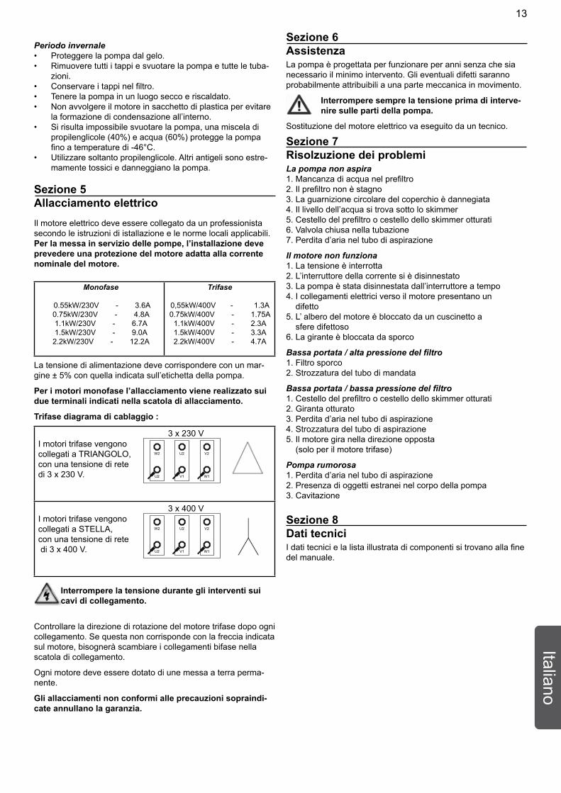
Trifase diagrama di cablaggio :
3 x 230 V I motori trifase vengono
W2 U2 V2
U2 V1 W1
collegati a TRIANGOLO,con una tensione di rete di 3 x 230 V.
3 x 400 VI motori trifase vengono
W2 U2 V2
U2 V1 W1
collegati a STELLA,con una tensione di rete di 3 x 400 V.
Interrompere la tensione durante gli interventi sui cavi di collegamento.
Controllare la direzione di rotazione del motore trifase dopo ogni collegamento. Se questa non corrisponde con la freccia indicata sul motore, bisognerà scambiare i collegamenti bifase nella scatola di collegamento.
Ogni motore deve essere dotato di une messa a terra perma-nente.
Gli allacciamenti non conformi alle precauzioni sopraindi-cate annullano la garanzia.
Sezione 6AssistenzaLa pompa è progettata per funzionare per anni senza che sia necessario il minimo intervento. Gli eventuali difetti saranno probabilmente attribuibili a una parte meccanica in movimento.
Interrompere sempre la tensione prima di interve-nire sulle parti della pompa.
Sostituzione del motore elettrico va eseguito da un tecnico.
Sezione 7Risolzuzione dei problemiLa pompa non aspira1. Mancanza di acqua nel prefiltro2. Il prefiltro non è stagno3. La guarnizione circolare del coperchio è dannegiata4. Il livello dell’acqua si trova sotto lo skimmer5. Cestello del prefiltro o cestello dello skimmer otturati6. Valvola chiusa nella tubazione7. Perdita d’aria nel tubo di aspirazione
Il motore non funziona1. La tensione è interrotta2. L’interruttore della corrente si è disinnestato3. La pompa è stata disinnestata dall’interruttore a tempo4. I collegamenti elettrici verso il motore presentano un difetto5. L’ albero del motore è bloccato da un cuscinetto a sfere difettoso6. La girante è bloccata da sporco
Bassa portata / alta pressione del filtro1. Filtro sporco2. Strozzatura del tubo di mandata
Bassa portata / bassa pressione del filtro1. Cestello del prefiltro o cestello dello skimmer otturati2. Giranta otturato3. Perdita d’aria nel tubo di aspirazione4. Strozzatura del tubo di aspirazione5. Il motore gira nella direzione opposta (solo per il motore trifase)
Pompa rumorosa1. Perdita d’aria nel tubo di aspirazione2. Presenza di oggetti estranei nel corpo della pompa3. Cavitazione
Sezione 8Dati tecniciI dati tecnici e la lista illustrata di componenti si trovano alla fine del manuale.
13
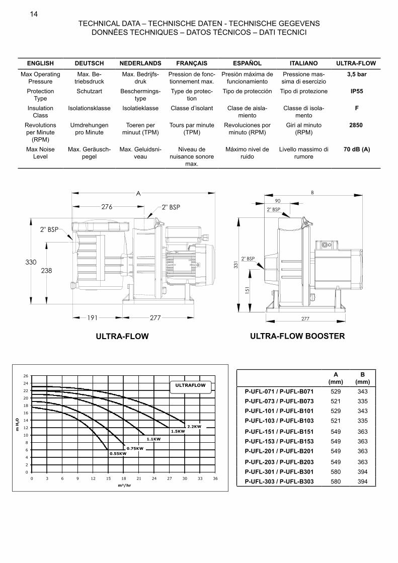
TECHNICAL DATA – TECHNISCHE DATEN - TECHNISCHE GEGEVENS DONNÉES TECHNIQUES – DATOS TÉCNICOS – DATI TECNICI
277
B
151
331
90
2" BSP
2" BSP
A (mm)
B(mm)
P-UFL-071 / P-UFL-B071 529 343P-UFL-073 / P-UFL-B073 521 335P-UFL-101 / P-UFL-B101 529 343P-UFL-103 / P-UFL-B103 521 335
P-UFL-151 / P-UFL-B151 549 363P-UFL-153 / P-UFL-B153 549 363P-UFL-201 / P-UFL-B201 549 363
P-UFL-203 / P-UFL-B203 549 363P-UFL-301 / P-UFL-B301 580 394P-UFL-303 / P-UFL-B303 580 394
ENGLISH DEUTSCH NEDERLANDS FRANÇAIS ESPAÑOL ITALIANO ULTRA-FLOW
Max Operating Pressure
Max. Be-triebsdruck
Max. Bedrijfs-druk
Pression de fonc-tionnement max.
Presión máxima de funcionamiento
Pressione mas-sima di esercizio
3,5 bar
Protection Type
Schutzart Beschermings-type
Type de protec-tion
Tipo de protección Tipo di protezione IP55
Insulation Class
Isolationsklasse Isolatieklasse Classe d’isolant Clase de aisla-miento
Classe di isola-mento
F
Revolutions per Minute
(RPM)
Umdrehungen pro Minute
Toeren per minuut (TPM)
Tours par minute (TPM)
Revoluciones por minuto (RPM)
Giri al minuto (RPM)
2850
Max Noise Level
Max. Geräusch-pegel
Max. Geluidsni-veau
Niveau de nuisance sonore
max.
Máximo nivel de ruido
Livello massimo di rumore
70 dB (A)
0
2
4
6
8
10
12
14
16
18
20
22
24
26
0 3 6 9 12 15 18 21 24 27 30 33 36
m H
2O
m3/hr
0.55KW0.75KW
1.1KW
1.5KW2.2KW
ULTRAFLOW
A
330
276
238
191 277
2" BSP
2" BSP
ULTRA-FLOW ULTRA-FLOW BOOSTER
14
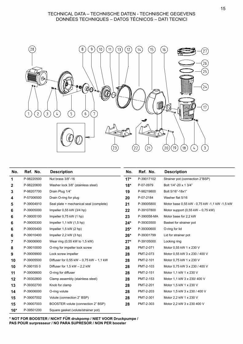
TECHNICAL DATA – TECHNISCHE DATEN - TECHNISCHE GEGEVENS DONNÉES TECHNIQUES – DATOS TÉCNICOS – DATI TECNICI
No. Ref. No. Description
1 P-98220500 Nut brass 3/8”-16
2 P-98220600 Washer lock 3/8” (stainless steel)
3 P-98207700 Drain Plug 1/4”
4 P-57006500 Drain O-ring for plug
5 P-39004910 Seal plate + mechanical seal (complete)
6 P-39005000 Impeller 0,55 kW (3/4 hp)
6 P-39005100 Impeller 0,75 kW (1 hp)
6 P-39005300 Impeller 1,1 kW (1,5 hp)
6 P-39005400 Impeller 1,5 kW (2 hp)
6 P-39010400 Impeller 2,2 kW (3 hp)
7 P-39006900 Wear ring (0,55 kW to 1,5 kW)
8 P-39010000 O-ring for impeller lock screw
9 P-39009900 Lock screw impeller
10 P-39005500 Diffuser for 0,55 kW – 0,75 kW – 1,1 kW
10 P-390155 0 Diffuser for 1,5 kW – 2,2 kW
11 P-39006600 O-ring for diffuser
12 P-39302800 Clamp assembly (stainless steel)
13 P-39302700 Knob for clamp
14 P-39006000 O-ring volute
15 P-39007002 Volute (connection 2” BSP)
15 P-39007003 BOOSTER volute (connection 2” BSP)
16* P-39501200 Square gasket (volute/strainer pot)
No. Ref. No. Description
17* P-39017102 Strainer pot (connection 2”BSP)
18* P-07-0979 Bolt 1/4”-20 x 1 3/4”
19 P-98219800 Bolt 5/16”-18x1”
20 P-07-2184 Washer flat 5/16
21 P-39005800 Motor base 0,55 kW - 0,75 kW -1,1 kW -1,5 kW
22 P-39107800 Motor support (0,55 kW – 0,75 kW)
23 P-390058-MA Motor base for 2,2 kW
24* P-39303500 Basket for strainer pot
25* P-39300600 O-ring for lid
26* P-39301799 Lid for strainer pot
27* P-39105000 Locking ring
28 PMT-2-071 Motor 0,55 kW 1 x 230 V
28 PMT-2-073 Motor 0,55 kW 3 x 230 / 400 V
28 PMT-2-101 Motor 0,75 kW 1 x 230 V
28 PMT-2-103 Motor 0,75 kW 3 x 230 / 400 V
28 PMT-2-151 Motor 1,1 kW 1 x 230 V
28 PMT-2-153 Motor 1,1 kW 3 x 230/ 400 V
28 PMT-2-201 Motor 1,5 kW 1 x 230 V
28 PMT-2-203 Motor 1,5 kW 3 x 230 / 400 V
28 PMT-2-301 Motor 2,2 kW 1 x 230 V
28 PMT-2-303 Motor 2,2 kW 3 x 230 400 V
* NOT FOR BOOSTER / NICHT FÜR drukpomp / NIET VOOR Druckpumpe / PAS POUR surpresseur / NO PARA SUPRESOR / NON PER booster
15

®
P-INSB-UFL (Rev. 02 / ’09)