ultima xi infrared gas monitor - mine safety appliances
TRANSCRIPT
Ultima® XI InfraredGas Monitor
Instruction Manual
THIS MANUAL MUST BE CAREFULLY READ BY ALL INDIVIDUALS WHO HAVE OR WILL
HAVE THE RESPONSIBILITY FOR USING OR SERVICING THE PRODUCT. Like any piece
of complex equipment, this device will perform as designed only if it is used and serviced
in accordance with the manufacturer’s instructions. OTHERWISE, IT COULD FAIL TO
PERFORM AS DESIGNED AND PERSONS WHO RELY ON THIS PRODUCT FOR THEIR
SAFETY COULD SUSTAIN SEVERE PERSONAL INJURY OR LOSS OF LIFE.
The warranties made by Mine Safety Appliances Company with respect to the product are
voided if the product is not used and serviced in accordance with the instructions in this
manual. Please protect yourself and others by following them. We encourage our
customers to write or call regarding this equipment prior to use or for any additional
information relative to use or service.
In the U.S., to contact your nearest stocking location, dial toll-free 1-800-MSA-INST
To contact MSA International, dial 1-412-967-3354.
© MINE SAFETY APPLIANCES COMPANY 2009 - All Rights Reserved
This manual is available on the internet at www.msanet.com.
Inquiries can also be e-mailed to [email protected].
Manufactured by
MSA NORTH AMERICAP.O. Box 427, Pittsburgh, Pennsylvania 15230
(L)-Y Rev 3 10052972
"! WARNING
i
MSA Permanent Instrument Warranty1. Warranty- Seller warrants that this product will be free from
mechanical defect or faulty workmanship for the following period:
• IR Sensor source: ten (10) years from date of shipment
• All other IR components: two (2) years from date of shipment.
This warranty is applicable provided it is maintained and used inaccordance with Seller's instructions and/ or recommendations.This warranty does not apply to expendable or consumable partswhose normal life expectancy is less than one (1) year. The Sellershall be released from all obligations under this warranty in theevent repairs or modifications are made by persons other than itsown or authorized service personnel or if the warranty claim resultsfrom physical abuse or misuse of the product. No agent, employeeor representative of the Seller has any authority to bind the Sellerto any affirmation, representation or warranty concerning the goodssold under this contract. Seller makes no warranty concerningcomponents or accessories not manufactured by the Seller, but willpass onto the Purchaser all warranties of manufacturers of suchcomponents. THIS WARRANTY IS IN LIEU OF ALL OTHERWARRANTIES, EXPRESSED, IMPLIED OR STATUTORY, AND ISSTRICTLY LIMITED TO THE TERMS HEREOF. SELLERSPECIFICALLY DISCLAIMS ANY WARRANTY OFMERCHANTABILITY OR OF FITNESS FOR A PARTICULARPURPOSE.
2. Exclusive Remedy- It is expressly agreed that Purchaser's soleand exclusive remedy for breach of the above warranty, for anytortious conduct of Seller, or for any other cause of action, shall bethe repair and/ or replacement at Seller's option, of any equipmentor parts thereof, which after examination by Seller is proven to bedefective. Replacement equipment and/ or parts will be provided atno cost to Purchaser, F.O.B. Seller's Plant. Failure of Seller tosuccessfully repair any nonconforming product shall not cause theremedy established hereby to fail of its essential purpose.
3. Exclusion of Consequential Damage- Purchaser specificallyunderstands and agrees that under no circumstances will seller beliable to purchaser for economic, special, incidental orconsequential damages or losses of any kind whatsoever, includingbut not limited to, loss of anticipated profits and any other losscaused by reason of non-operation of the goods. This exclusion isapplicable to claims for breach of warranty, tortious conduct or anyother cause of action against seller.
General Warnings and Cautions
1. The Ultima XI Infrared Gas Monitors described in this manual must be installed, operated and maintained in strict accordancewith their labels, cautions, warnings,instructions, and within thelimitations stated. Verify that the class, group, and temperatureratings of the equipment agree with the actual classification of the location.
2. The Ultima XI Infrared Gas Monitor is designed to detect gases or vapors in air. It can also measure the concentration of gases orvapors in steam or inert or oxygen-deficient atmospheres. .
3. Use only genuine MSA replacement parts when performing anymaintenance procedures provided in this manual. Failure to do somay seriously impair instrument performance. Repair or alterationof the Ultima XI Infrared Gas Monitor, beyond the scope of thesemaintenance instructions or by anyone other than authorized MSAservice personnel, could cause the product to fail to perform asdesigned.
4. The Ultima XI Infrared Gas Monitor detects the presence of mostcombustible gases by identifying the difference in the amount ofinfrared light energy absorbed during the presence of these gases.This monitor, however, does NOT detect the presence of hydrogengas and must never be used to monitor for hydrogen gas.
5. The standard Ultima XI Infrared Gas Monitor does not detect thepresence of acetylene gas. The presence of acetylene gas willdesensitize sensor performance. Custom-built acetylene sensorsare available through your MSA representative.
6. CSA performance Certification to standard C22.2 No. 152 is validonly when the instrument is calibrated on methane per theinstruction manual.
" WARNING
ii
1. As with all gas monitors of this type, high levels of, or longexposure to, certain compounds in the tested atmosphere couldcontaminate the sensors. In atmospheres where an Ultima XIInfrared Gas Monitor may be exposed to such materials, calibrationmust be performed frequently to ensure that operation isdependable and display indications are accurate.
2. The Ultima XI Infrared Gas Monitor must not be painted. If paintingis done in an area where a Monitor is located, care must beexercised to ensure that paint is not deposited on theenvironmental shield of the Ultima XI Infrared Gas Monitor, if soequipped. Such paint deposits would interfere with the diffusionprocess, whereby a sample of the atmosphere being monitoreddiffuses into the Monitor.
3. The only absolute method to ensure proper operation of an UltimaXI Infrared Monitor is to check it with a known concentration of thegas for which it has been calibrated. Consequently, calibrationchecks must be included as part of the routine inspection of thesystem.
4. Protect the Ultima XI Infrared Gas Monitor from extreme vibration.
FAILURE TO FOLLOW THE ABOVE CAN RESULT IN PRODUCTDAMAGE AND/OR AN UNSAFE CONDITION.
" CAUTION
iii
Table of Contents
Chapter 1, Installation . . . . . . . . . . . . . . . . . . . . . . . . . . . . . .1-1
General Description . . . . . . . . . . . . . . . . . . . . . . . . . . . . . . . . .1-1
Identifying Your Unit . . . . . . . . . . . . . . . . . . . . . . . . . . . . . . . .1-1
Installing Your Gas Monitor . . . . . . . . . . . . . . . . . . . . . . . . . . .1-2
Ultima XI Electrical Connections . . . . . . . . . . . . . . . . . . . . . . .1-4
For Milliamp Output . . . . . . . . . . . . . . . . . . . . . . . . . . .1-5
Chapter 2, Start-up and Calibration . . . . . . . . . . . . . . . . . . .2-1
Calibration Basics . . . . . . . . . . . . . . . . . . . . . . . . . . . . . . . . . .2-1
Ultima XI Calibration . . . . . . . . . . . . . . . . . . . . . . . . . . . . . . . .2-2
Calibration Kit . . . . . . . . . . . . . . . . . . . . . . . . . . . . . . .2-5
Chapter 3, Specifications . . . . . . . . . . . . . . . . . . . . . . . . . . . .3-1
Chapter 4, Maintenance . . . . . . . . . . . . . . . . . . . . . . . . . . . . .4-1
General . . . . . . . . . . . . . . . . . . . . . . . . . . . . . . . . . . . . . . .4-1
Ultima XI Cleaning Procedure . . . . . . . . . . . . . . . . . . . . . . . . .4-1
Appendix A,Calibration Guide for Additional XI Gases . . . . . . . . . . . . . . . . . . . .A-1
iv
List of FiguresFigure 1-1. Explosion-Proof Ultima XI Infrared Gas Monitor .1-1
Figure 1-2. Explosion-Proof Ultima XI Infrared Gas Monitor
with Junction Box . . . . . . . . . . . . . . . . . . . . . . . . .1-2
Figure 1-3. Ultima XI Infrared Gas Monitor . . . . . . . . . . . . . . .1-3
Figure 1-4. Ultima XI Installation Requirements . . . . . . . . . . .1-4
Figure 1-5. Ultima XI Infrared Gas Monitor
with Junction Box . . . . . . . . . . . . . . . . . . . . . . . . .1-5
Figure 2-1. Intrinsically Safe Ultima XI Calibration Cap . . . . .2-3
Figure 2-2. Calibration Sequence Diagram . . . . . . . . . . . . . . .2-3
Figure 2-3. Environmental Guard . . . . . . . . . . . . . . . . . . . . . .2-4
List of TablesTable 1-1. Ultima XI Maximum Cable Length
& 4-20 mA Signal Load . . . . . . . . . . . . . . . . . . . .1-5
Table 2-1. Instrument Operation . . . . . . . . . . . . . . . . . . . . . . .2-1
Table 2-2. Calibration Kit Table . . . . . . . . . . . . . . . . . . . . . . .2-5
Table 3-1 . Performance Specifications . . . . . . . . . . . . . . . . .3-1
Table 3-2. Certification and Approval . . . . . . . . . . . . . . . . . . .3-2
Table 3-3. Installation Drawings . . . . . . . . . . . . . . . . . . . . . . .3-2
Table 4-1. Parts List . . . . . . . . . . . . . . . . . . . . . . . . . . . . . . . . .4-3
v
1-1
Chapter 1, Installation
General Description
The Ultima XI Infrared Gas Monitor is designed to sample theenvironment where mounted and alert you to potentially dangerouslevels of combustible gas. The Ultima XI Infrared Gas Monitor isshipped factory-calibrated and is labeled with target gas, calibration gasand span setting information. The target gas is not field-configurableand cannot be changed. The Ultima XI Gas Monitor is a stand-aloneunit with a 4 to 20 mA output.
Identifying Your Unit
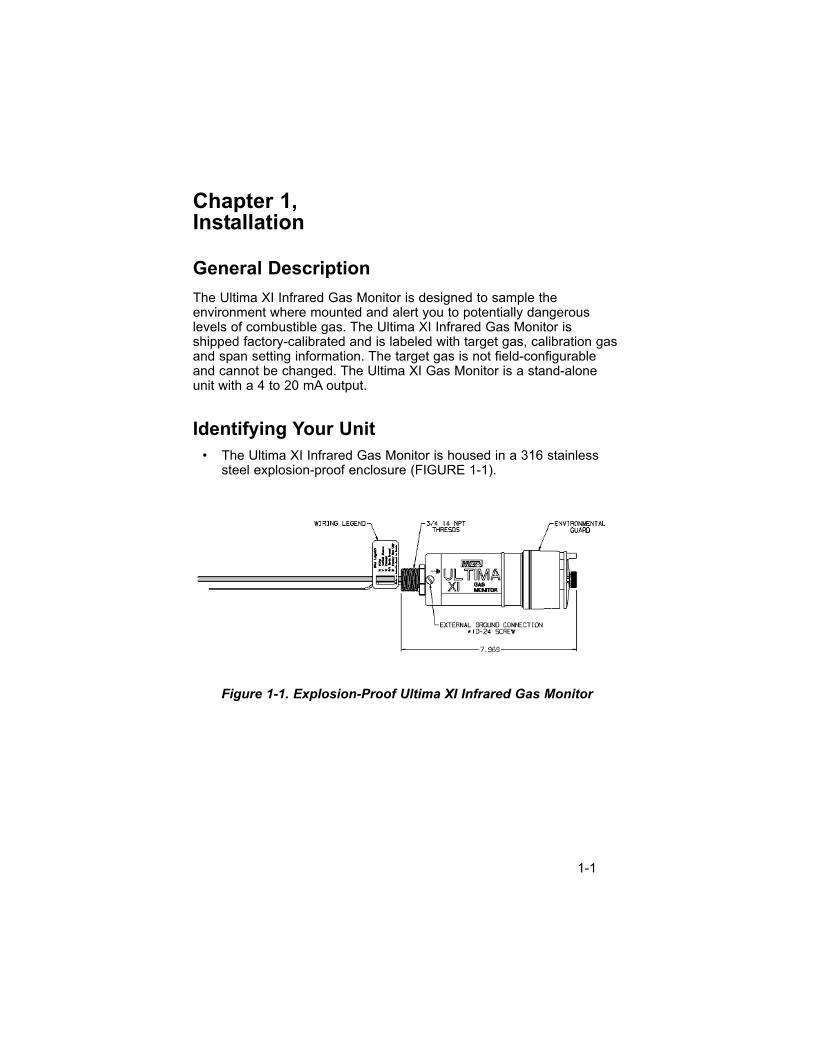
• The Ultima XI Infrared Gas Monitor is housed in a 316 stainlesssteel explosion-proof enclosure (FIGURE 1-1).
Do not mix units with different area classifications. All units
Figure 1-1. Explosion-Proof Ultima XI Infrared Gas Monitor
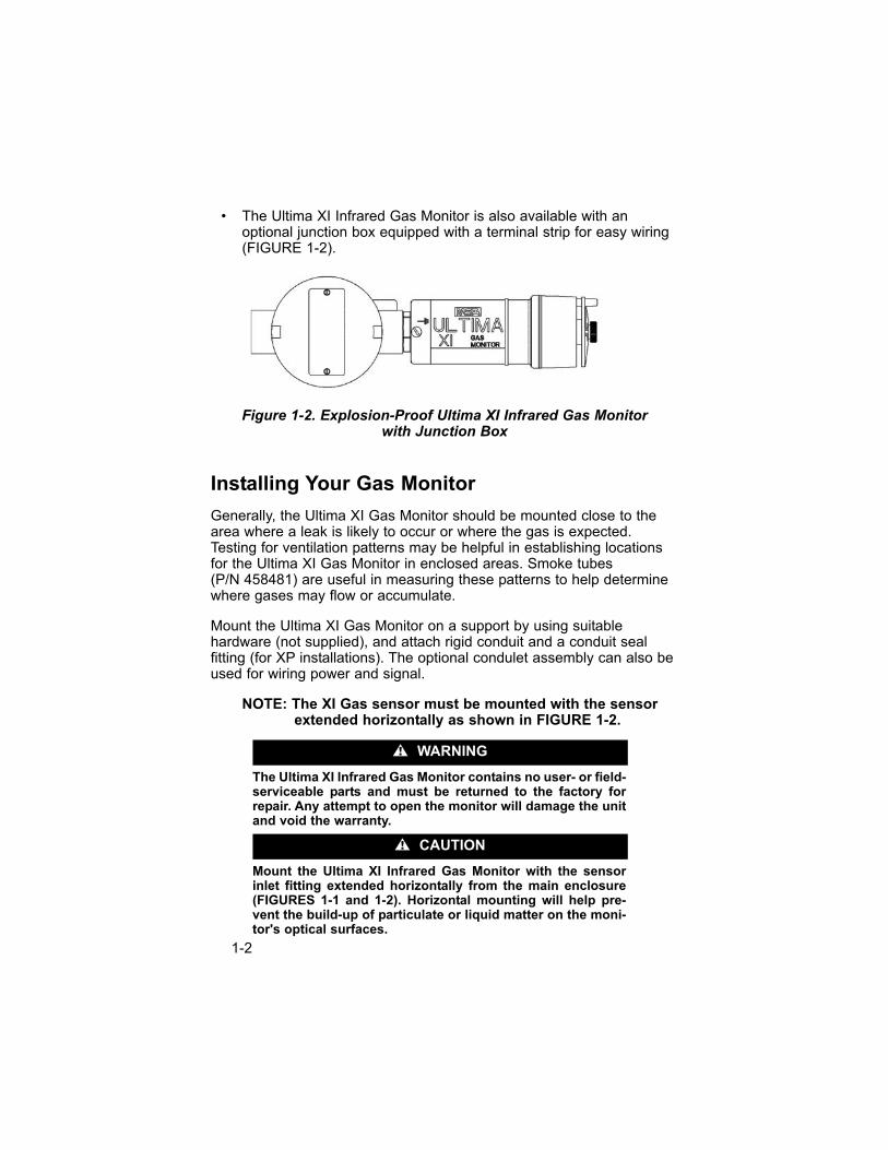
• The Ultima XI Infrared Gas Monitor is also available with anoptional junction box equipped with a terminal strip for easy wiring(FIGURE 1-2).
Do not mix units with different area classifications. All units
Installing Your Gas Monitor
Generally, the Ultima XI Gas Monitor should be mounted close to thearea where a leak is likely to occur or where the gas is expected.Testing for ventilation patterns may be helpful in establishing locationsfor the Ultima XI Gas Monitor in enclosed areas. Smoke tubes (P/N 458481) are useful in measuring these patterns to help determinewhere gases may flow or accumulate.
Mount the Ultima XI Gas Monitor on a support by using suitablehardware (not supplied), and attach rigid conduit and a conduit sealfitting (for XP installations). The optional condulet assembly can also beused for wiring power and signal.
NOTE: The XI Gas sensor must be mounted with the sensorextended horizontally as shown in FIGURE 1-2.
The Ultima XI Infrared Gas Monitor contains no user- or field-serviceable parts and must be returned to the factory forrepair. Any attempt to open the monitor will damage the unitand void the warranty.
Mount the Ultima XI Infrared Gas Monitor with the sensorinlet fitting extended horizontally from the main enclosure(FIGURES 1-1 and 1-2). Horizontal mounting will help pre-vent the build-up of particulate or liquid matter on the moni-tor's optical surfaces.
" CAUTION
" WARNING
Figure 1-2. Explosion-Proof Ultima XI Infrared Gas Monitorwith Junction Box
1-2
Do not paint the Ultima XI Infrared Gas Monitor. If painting isdone in an area where a sensor is located, exercise cautionto ensure paint is not deposited on the sensor inlet fitting.Such paint deposits would interfere with the diffusionprocess, whereby a sample of the monitored atmospherediffuses into the sensor. In addition, solvents in the paintmay cause an alarm condition to occur.
Protect the Ultima XI Infrared Gas Monitor from extremevibration. Do not mount sensing head in direct sunlight asthis may cause the sensor to overheat.
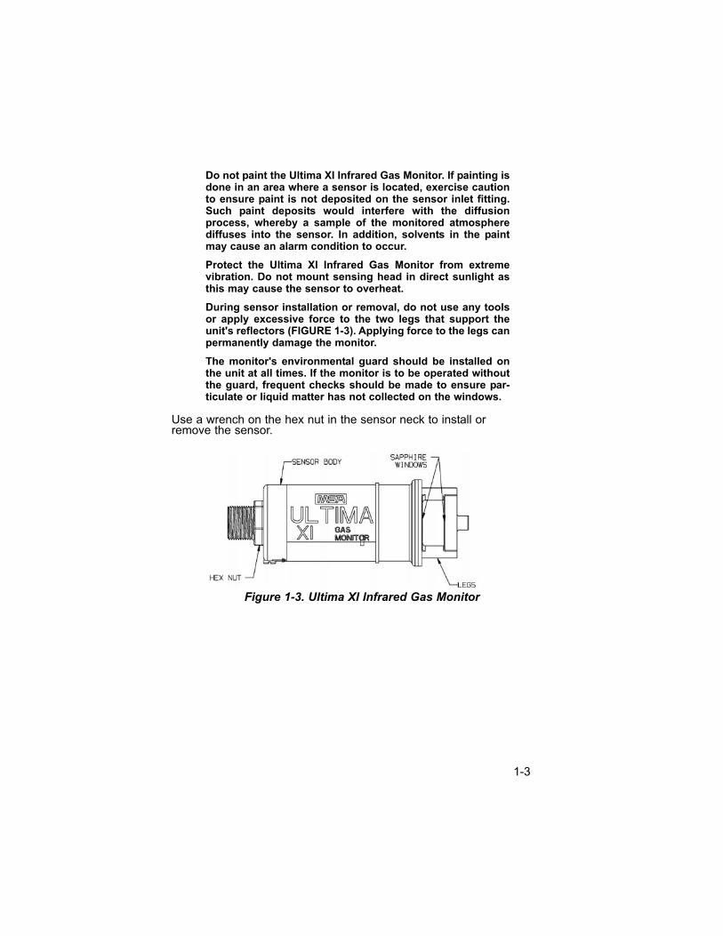
During sensor installation or removal, do not use any toolsor apply excessive force to the two legs that support theunit's reflectors (FIGURE 1-3). Applying force to the legs canpermanently damage the monitor.
The monitor's environmental guard should be installed onthe unit at all times. If the monitor is to be operated withoutthe guard, frequent checks should be made to ensure par-ticulate or liquid matter has not collected on the windows.
Use a wrench on the hex nut in the sensor neck to install or remove the sensor.
Do not mix units with different area classifications. All units
Figure 1-3. Ultima XI Infrared Gas Monitor
1-3
Ultima XI Electrical Connections
The Ultima XI Gas Monitor is provided with input wires for power andsignal connections. An optional condulet assembly is also available.
An external power supply is required.
• For power requirements, see Chapter 3, "Specifications".
• All connections should be made by following appropriate wire codeprocedures.
NOTE: Refer to TABLE 3-3 for appropriate installation drawing.
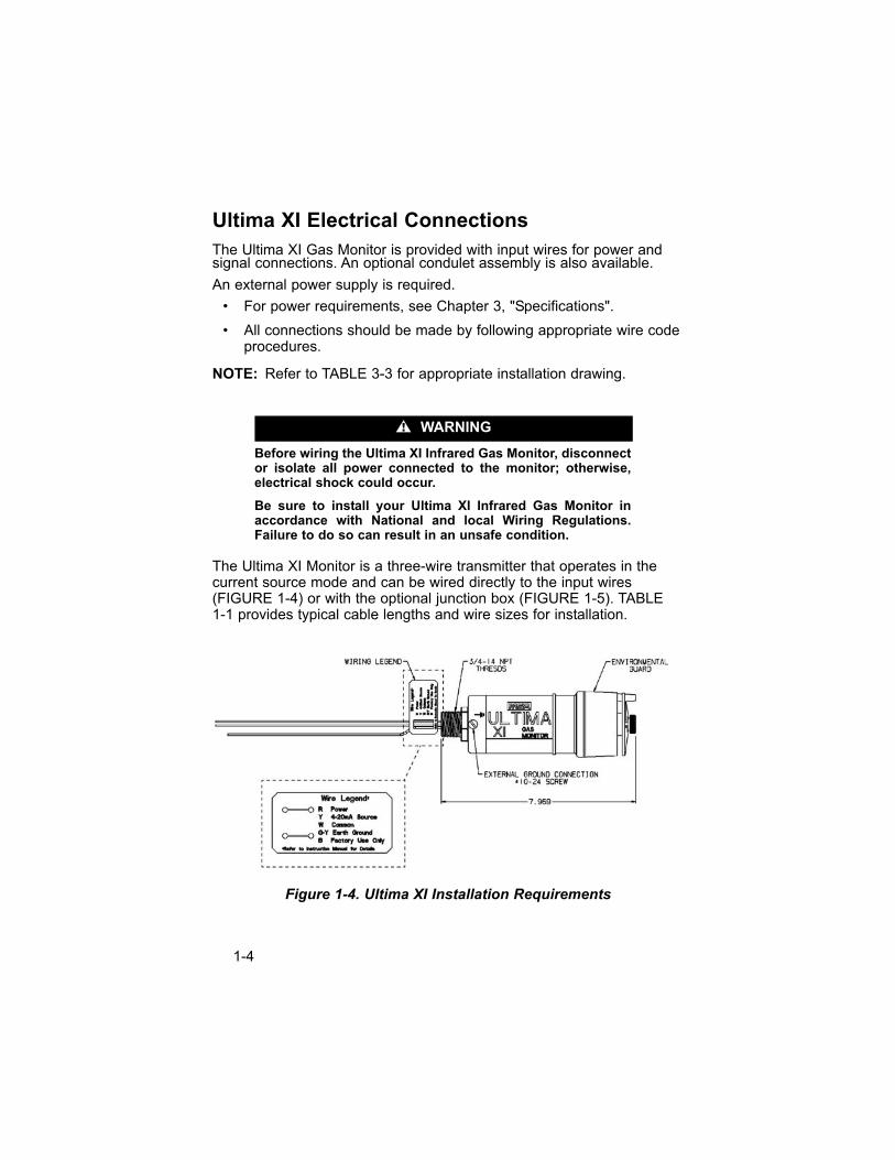
Before wiring the Ultima XI Infrared Gas Monitor, disconnector isolate all power connected to the monitor; otherwise,electrical shock could occur.
Be sure to install your Ultima XI Infrared Gas Monitor inaccordance with National and local Wiring Regulations.Failure to do so can result in an unsafe condition.
The Ultima XI Monitor is a three-wire transmitter that operates in thecurrent source mode and can be wired directly to the input wires(FIGURE 1-4) or with the optional junction box (FIGURE 1-5). TABLE1-1 provides typical cable lengths and wire sizes for installation.
" WARNING
Figure 1-4. Ultima XI Installation Requirements
1-4
Do not mix units with different area classifications. All units
Table 1-1. Ultima XI Maximum Cable Length & 4-20 mA Signal Load
POWER SUPPLY 24 VOLTS 12 VOLTS
18 AWG CABLE 2,000 feet 300 feet
16 AWG CABLE 3,500 feet 500 feet
12 AWG CABLE 5,000 feet 900 feet
4 - 20 mA SIGNAL MAXIMUM LOAD 600 OHMS 300 OHMS
• In all installations, twisted-pair, instrument quality cable isrecommended. Shielded cable is recommended for cable runswhere radio frequency interference (RFI), electromagneticinterference (EMl), or other noise sources exist (such as motors,welding equipment, heaters, etc.).
• Conduit may also be needed in areas where a large amount ofelectrical noise is expected.
Proper installation should ensure that water and dirt are not able toenter the unit via the wire or conduit.
For Milliamp Output
The Ultima XI Infrared Gas Monitor may be connected to any devicecapable of accepting a 4 to 20 mA analog signal, such as:
• SUPREMA (with 4 to 20 mA input modules)
• 9010/9020 Controller
• Gasgard® Family of Controllers
• DCS’s, etc.
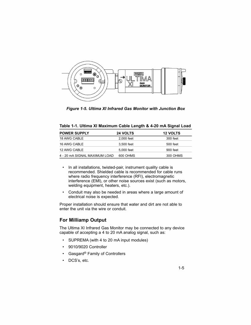
Figure 1-5. Ultima XI Infrared Gas Monitor with Junction Box
1-5
Chapter 2, Start-up and Calibration
The Ultima XI Infrared Gas Monitor is factory-calibrated and ready forimmediate use. The Ultima XI Gas Monitor provides a 4 to 20 mA outputsignal that can be used in conjunction with data acquisition controllers.
During instrument operation, the 4 to 20 mA output signal provides theinformation shown in TABLE 2-1.
Table 2-1. Instrument Operation
OPERATION 4 to 20 mA
NORMAL, NO ALARMS Gas value
ALARMING Gas value
FAULT 3.0 mA
POWER UP/ COUNTDOWN 3.75 mA (approximately 65 seconds)
SENSOR CAL 3.75 mA
CAL FAULT Gas value
UNDER-RANGE 3.0 mA if gas value 0 or less; gas value otherwise
OVER-RANGE 21.0 mA
Calibration Basics
• While the Ultima XI Infrared Gas Monitor is factory-calibrated, it isgood practice to calibrate the unit once it is installed in its finalenvironmental destination.
• As with any type of gas monitor, the only true check of itsperformance is to apply gas directly to the sensor. The frequencyof the calibration gas tests depends on the operating time andchemical exposures of the sensors. New sensors should becalibrated more often until the calibration records prove sensorstability. The calibration frequency can then be reduced to theschedule set by the safety officer or plant manager.
• Before calibrating, the Ultima XI Infrared Gas Monitor must bepowered for a minimum of one hour to allow the sensor to settleinto its new environment.
• Output signal during calibration is 3.75 mA.
2-1

• Read all calibration instructions before attempting an actualcalibration.
• Identify and become familiar with all of the calibration components.
• During the calibration, it may be necessary to quickly apply thespan gas to the unit. Prior connection of the calibrationcomponents will aid in the ease of unit calibration.
• The only true check of any gas monitor's performance is to applygas directly to the sensor.
• The calibration procedure must be performed regularly.
Before attempting a calibration, power the monitor for atleast one full hour. To ensure a fully functional sensor, per-form a calibration check and adjustments at initial start-upand at regular intervals.
Ultima XI Calibration
• Although a full calibration (zero and span) can be performed on theUltima XI Infrared Gas Monitor, a no-gas (zero) calibration issufficient to properly calibrate the monitor.
• Normally, any degradation of the sensor's performance isassociated with slight drifts in its zero response that, in turn, willadversely affect its span performance. Restoring the sensor's zerois typically sufficient to restore its span performance.
• The following steps are required to perform an Ultima XIcalibration.
• The calibration sequence diagram is shown in FIGURE 2-2.
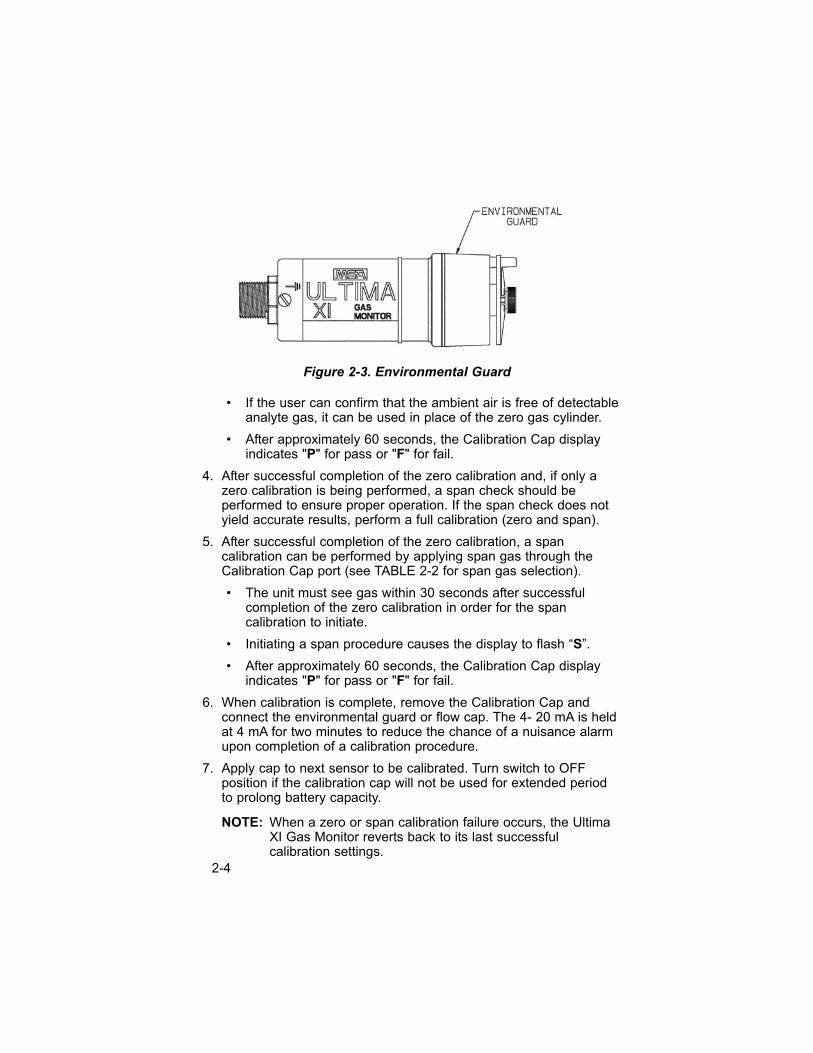
1. Remove the environmental guard or flow cap from the Ultima XIGas Monitor (FIGURE 2-3).
2. Turn the switch on the calibration cap to the ON position.
3. Connect the Ultima XI Calibration Cap (FIGURE 2-1) to the UltimaXI Gas Monitor.
• The Calibration Cap display flashes "-", indicating the cap isinterfacing with the Ultima XI Gas Monitor.
• The Calibration Cap display flashes "C", indicating the unit is inzero calibration mode.
" CAUTION
2-2
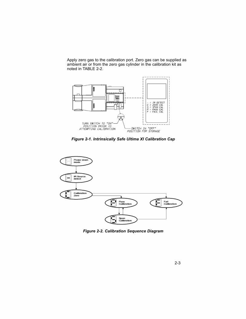
Apply zero gas to the calibration port. Zero gas can be supplied asambient air or from the zero gas cylinder in the calibration kit asnoted in TABLE 2-2.
Do not mix units with different area classifications. All units
Do not mix units with different area classifications. All units
Figure 2-2. Calibration Sequence Diagram
Figure 2-1. Intrinsically Safe Ultima XI Calibration Cap
2-3
• If the user can confirm that the ambient air is free of detectableanalyte gas, it can be used in place of the zero gas cylinder.
• After approximately 60 seconds, the Calibration Cap displayindicates "P" for pass or "F" for fail.
4. After successful completion of the zero calibration and, if only azero calibration is being performed, a span check should beperformed to ensure proper operation. If the span check does notyield accurate results, perform a full calibration (zero and span).
5. After successful completion of the zero calibration, a spancalibration can be performed by applying span gas through theCalibration Cap port (see TABLE 2-2 for span gas selection).
• The unit must see gas within 30 seconds after successfulcompletion of the zero calibration in order for the spancalibration to initiate.
• Initiating a span procedure causes the display to flash “S”.
• After approximately 60 seconds, the Calibration Cap displayindicates "P" for pass or "F" for fail.
6. When calibration is complete, remove the Calibration Cap andconnect the environmental guard or flow cap. The 4- 20 mA is heldat 4 mA for two minutes to reduce the chance of a nuisance alarmupon completion of a calibration procedure.
7. Apply cap to next sensor to be calibrated. Turn switch to OFFposition if the calibration cap will not be used for extended periodto prolong battery capacity.
NOTE: When a zero or span calibration failure occurs, the UltimaXI Gas Monitor reverts back to its last successfulcalibration settings.
Figure 2-3. Environmental Guard
2-4
NOTE: If the Ultima XI Calibration Cap is left on for more thanfifteen minutes after calibration concludes, the 4 to 20 mAsignal indicates a fault status.
The Calibration Cap must be removed from the XI sensorafter completing the Zeroing and/or Spanning procedure;otherwise, the sensor cannot perform properly.
Calibration Kit
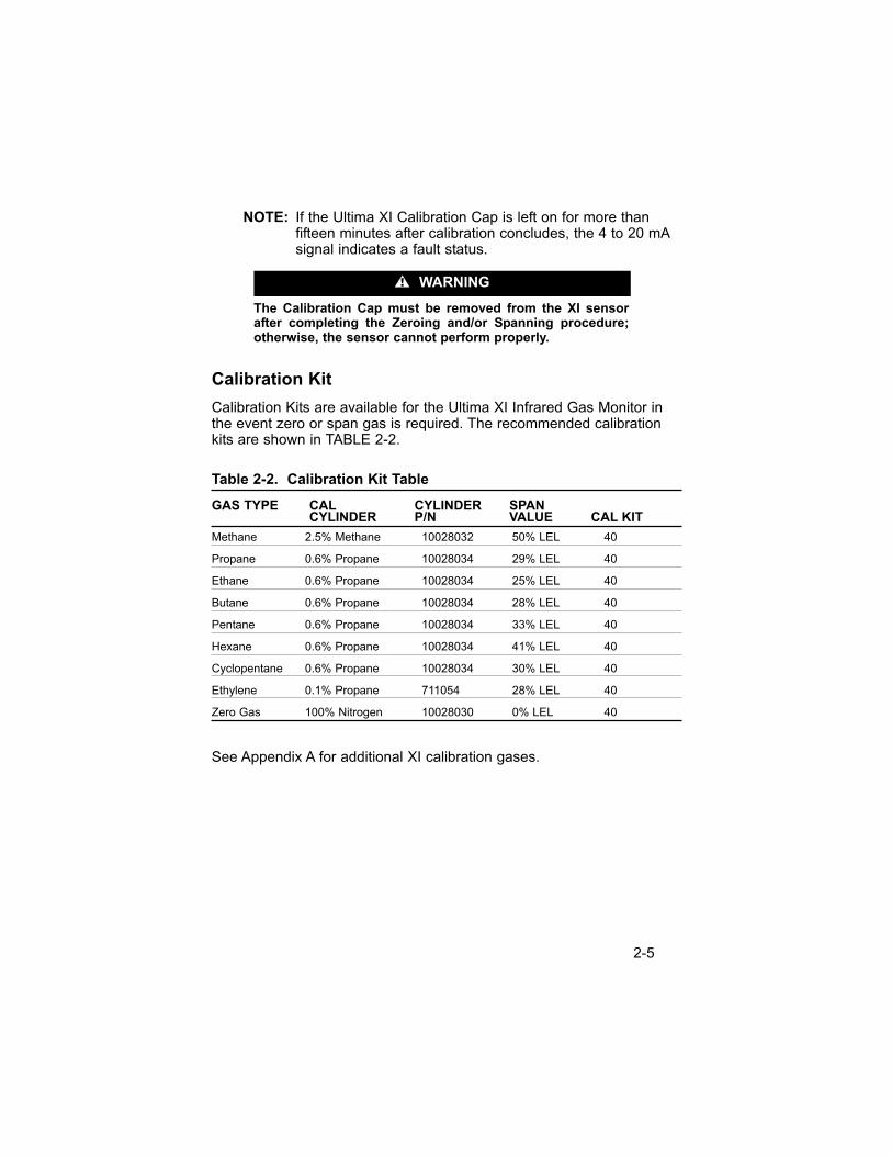
Calibration Kits are available for the Ultima XI Infrared Gas Monitor inthe event zero or span gas is required. The recommended calibrationkits are shown in TABLE 2-2.
Table 2-2. Calibration Kit Table
GAS TYPE CAL CYLINDER SPANCYLINDER P/N VALUE CAL KIT
Methane 2.5% Methane 10028032 50% LEL 40
Propane 0.6% Propane 10028034 29% LEL 40
Ethane 0.6% Propane 10028034 25% LEL 40
Butane 0.6% Propane 10028034 28% LEL 40
Pentane 0.6% Propane 10028034 33% LEL 40
Hexane 0.6% Propane 10028034 41% LEL 40
Cyclopentane 0.6% Propane 10028034 30% LEL 40
Ethylene 0.1% Propane 711054 28% LEL 40
Zero Gas 100% Nitrogen 10028030 0% LEL 40
See Appendix A for additional XI calibration gases.
" WARNING
2-5
Chapter 3, Specifications
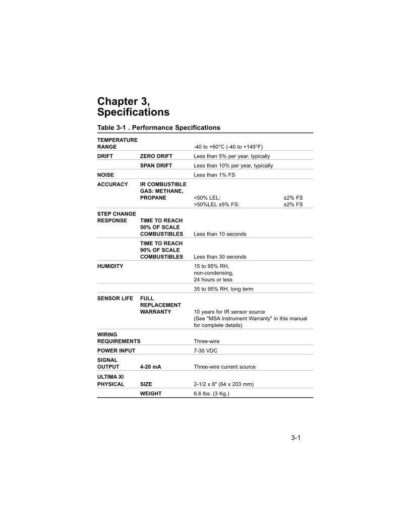
Table 3-1 . Performance Specifications
TEMPERATURE
RANGE -40 to +60°C (-40 to +149°F)
DRIFT ZERO DRIFT Less than 5% per year, typically
SPAN DRIFT Less than 10% per year, typically
NOISE Less than 1% FS
ACCURACY IR COMBUSTIBLE
GAS: METHANE,
PROPANE <50% LEL: ±2% FS
>50%LEL ±5% FS: ±2% FS
STEP CHANGE
RESPONSE TIME TO REACH
50% OF SCALE
COMBUSTIBLES Less than 10 seconds
TIME TO REACH
90% OF SCALE
COMBUSTIBLES Less than 30 seconds
HUMIDITY 15 to 95% RH,
non-condensing,
24 hours or less
35 to 95% RH, long term
SENSOR LIFE FULL
REPLACEMENT
WARRANTY 10 years for IR sensor source
(See "MSA Instrument Warranty" in this manual
for complete details)
WIRING
REQUIREMENTS Three-wire
POWER INPUT 7-30 VDC
SIGNAL
OUTPUT 4-20 mA Three-wire current source
ULTIMA XI
PHYSICAL SIZE 2-1/2 x 8" (64 x 203 mm)
WEIGHT 6.6 lbs. (3 Kg.)
3-1
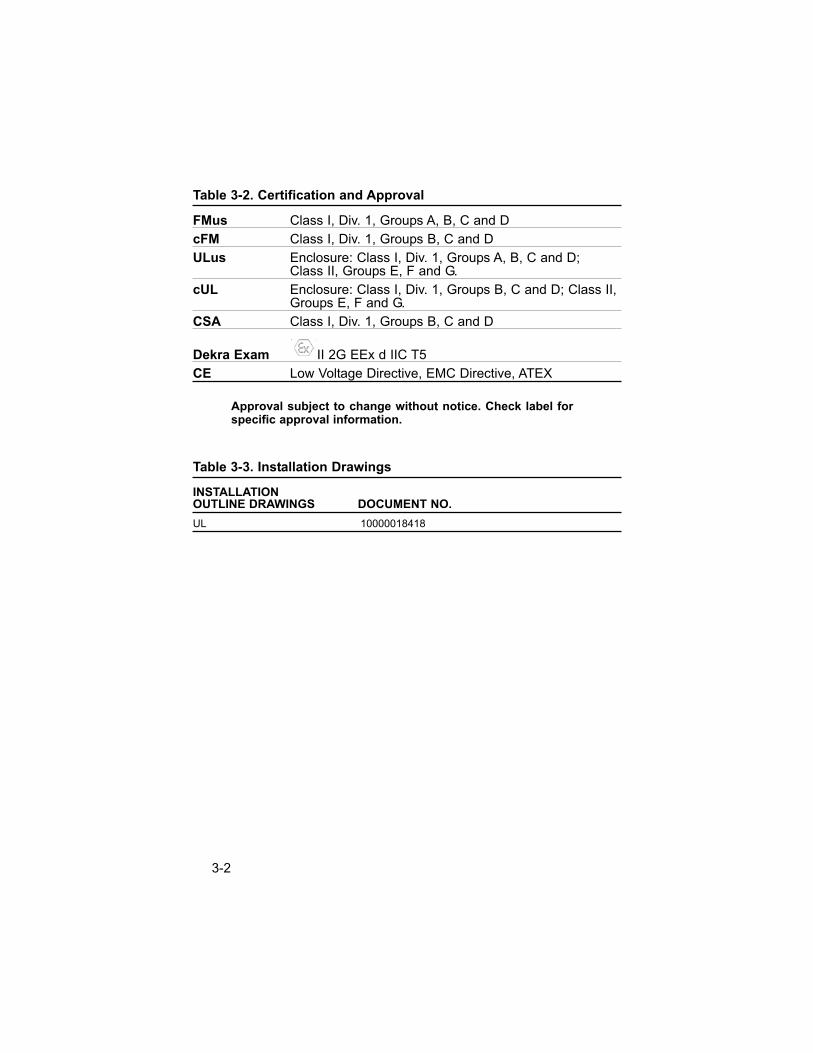
Table 3-2. Certification and Approval
FMus Class I, Div. 1, Groups A, B, C and D
cFM Class I, Div. 1, Groups B, C and D
ULus Enclosure: Class I, Div. 1, Groups A, B, C and D; Class II, Groups E, F and G.
cUL Enclosure: Class I, Div. 1, Groups B, C and D; Class II, Groups E, F and G.
CSA Class I, Div. 1, Groups B, C and D
Dekra Exam II 2G EEx d IIC T5
CE Low Voltage Directive, EMC Directive, ATEX
Approval subject to change without notice. Check label forspecific approval information.
Table 3-3. Installation Drawings
INSTALLATION OUTLINE DRAWINGS DOCUMENT NO.
UL 10000018418
3-2
Chapter 4, Maintenance
General
The Ultima XI Infrared Gas Monitor is:
• not field-serviceable and must be returned to the factory for repair.
• constantly performing a self-check.
When a critical error is detected in the unit, the 4 to 20 mA outputsignal goes to the 3.0 mA fault condition.
Ultima XI Cleaning Procedure
The presence of particulate matter, oil films, liquid water, or the residuefrom water drops on the two monitor windows can adversely affect itsperformance. The environmental guard is designed to prevent foreignsolids or liquids from reaching the monitor's optical system. Additionally,heating elements are incorporated into the unit to prevent watercondensation. Under severe conditions, however, some material maycollect on these surfaces and it may be necessary to occasionally checkand clean the windows.
1. Remove the environmental or flow cap.
2. Place an opaque object (piece of paper, end of wrench handle,etc.) between the light source window and the mirror to completelyobscure the light path for two to three seconds.
• The Ultima XIR/Ultima XI Monitor enters the Cleaning Mode for two minutes.
NOTE: While in the Cleaning Mode, the sensor will notrespond to the presence of gas.
• The analog current output is 3.0 mA during this time.
• The display indicates 'low signal'’.
4-1
3. While both windows are made of a highly durable material that isnot easily scratched, avoid excessive pressure when cleaningthem. Clean, cotton-tipped applicators are the most convenient toolto remove material collected on the windows.
• Use a dry applicator or one moistened with distilled water towipe the window and remove dust.
• Use an additional clean, dry applicator to remove any residualwater.
• Use an applicator moistened with isopropyl alcohol to removeheavy deposits of solids, liquids or oil films. Clean the windowagain with a second applicator moistened with distilled water;then, dry the window with a final applicator.
• Avoid using excessive amounts of water or alcohol in thecleaning procedure, and inspect the window to ensure that theentire surface is clean.
• The unit remains in the Cleaning Mode for a minimum oftwo minutes. If active cleaning is still in progress at the endof this period, the sensor detects the motion of this objectin its light path and automatically extends the CleaningMode for 15 seconds. Further 15-second Cleaning Modeextensions continue until no motion is detected.
NOTE: When the cleaning process is complete, be sure toremove all objects from the light path.
4. When exiting the Cleaning Mode, the unit returns to normaloperation. If water or isopropyl alcohol was used, allow the unit to operate for 15 minutes to completely dry beforereplacing the environmental guard and continuing to monitor for combustible gas.
5. Replace the environmental or flow cap.
6. After cleaning the windows, it is advisable to check the sensor’sresponse to both zero and calibration gas.
4-2

Do not place foreign objects in the sensor's analytical region(except per the Cleaning Procedure above); otherwise, theinfrared beam can be partially blocked, causing the sensorto generate false readings. All objects must be removedfrom the sensor's analytical region for it to function properly.
Similarly, if water or isopropyl alcohol is used to clean thesensor's windows, any residue from the cleaning proceduremust be completely dissipated before returning the unit toservice.
Checking the sensor's response to zero gas is the best wayto purge residual cleaning materials from the sensor and tomake sure that sensor's reading is stable before zeroing orcalibrating the sensor (see Chapter 2, "Start-up andCalibration").
Table 4-1. Parts List
PART PART NO.
Environmental Guard 10041265
Flow Cap 10042600
Calibration Cap 10048801
" CAUTION
4-3
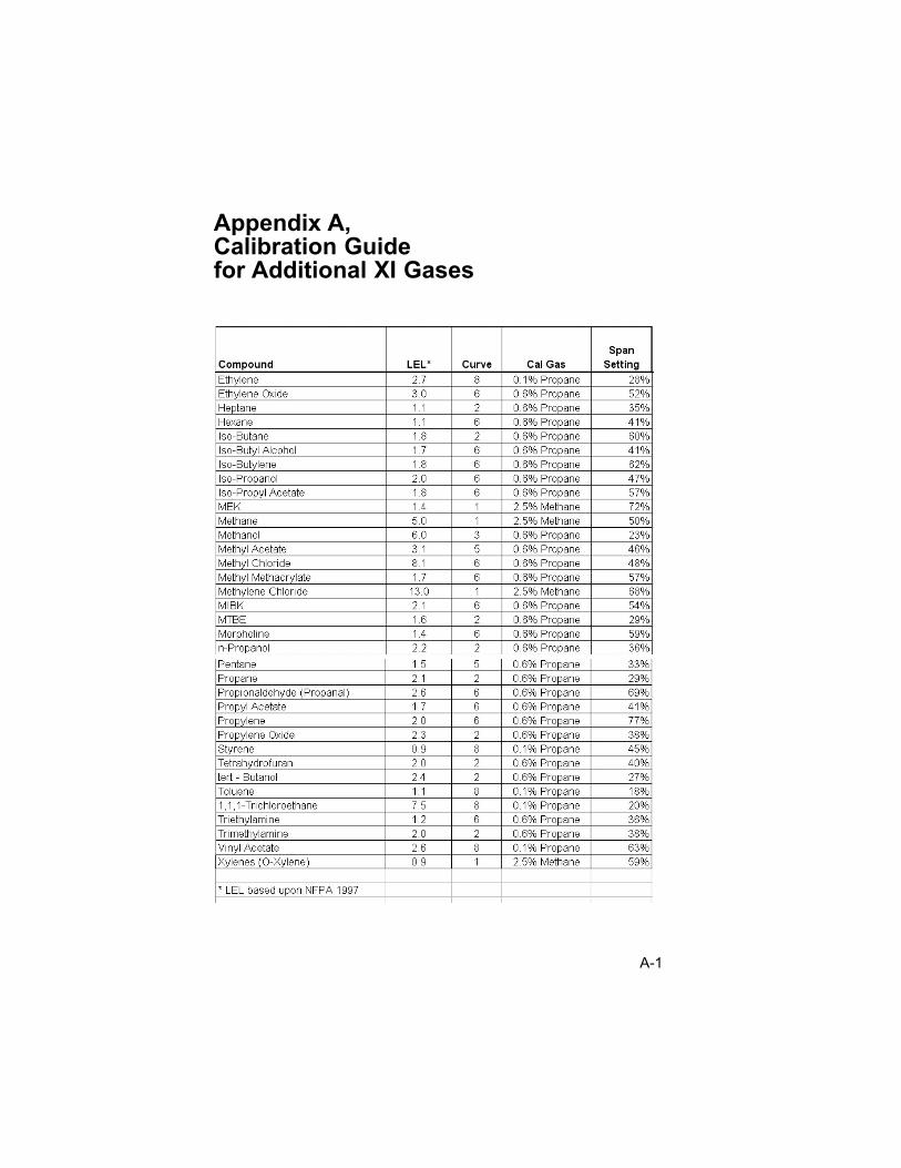
Appendix A,Calibration Guidefor Additional XI Gases
A-1