ulc-2 metaphase technologies - sensors incorporated ulc-2 product... · pg. 2 p. metaphase ulc-2...
TRANSCRIPT
pg. 1 metaphase-tech.com
MetaphaseTechnologiesULC-2
ULC
MetaphaseTechnologiesVersion 6.2
June 12, 2013
USER MANUAL
pg. 2 metaphase-tech.com
MetaphaseTechnologiesULC-2
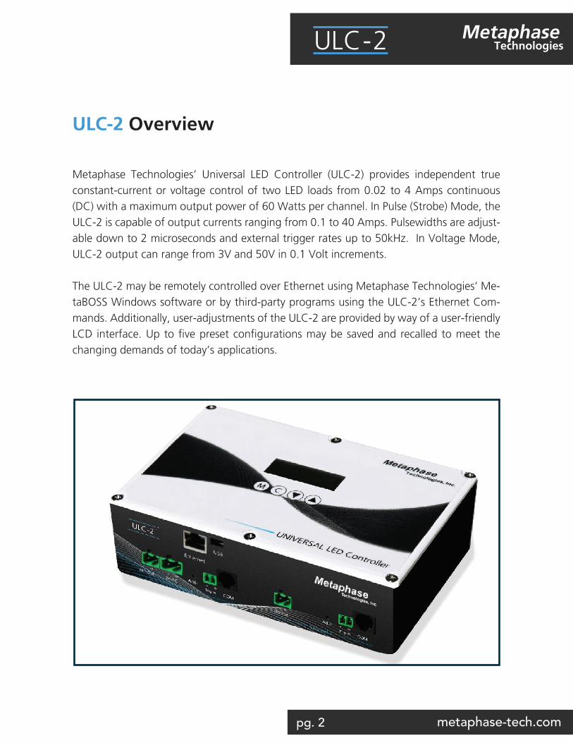
ULC-2 Overview
Metaphase Technologies’ Universal LED Controller (ULC-2) provides independent true constant-current or voltage control of two LED loads from 0.02 to 4 Amps continuous (DC) with a maximum output power of 60 Watts per channel. In Pulse (Strobe) Mode, the ULC-2 is capable of output currents ranging from 0.1 to 40 Amps. Pulsewidths are adjust-able down to 2 microseconds and external trigger rates up to 50kHz. In Voltage Mode, ULC-2 output can range from 3V and 50V in 0.1 Volt increments.
The ULC-2 may be remotely controlled over Ethernet using Metaphase Technologies’ Me-taBOSS Windows software or by third-party programs using the ULC-2’s Ethernet Com-mands. Additionally, user-adjustments of the ULC-2 are provided by way of a user-friendly LCD interface. Up to five preset configurations may be saved and recalled to meet the changing demands of today’s applications.
pg. 3 metaphase-tech.com
MetaphaseTechnologiesULC-2
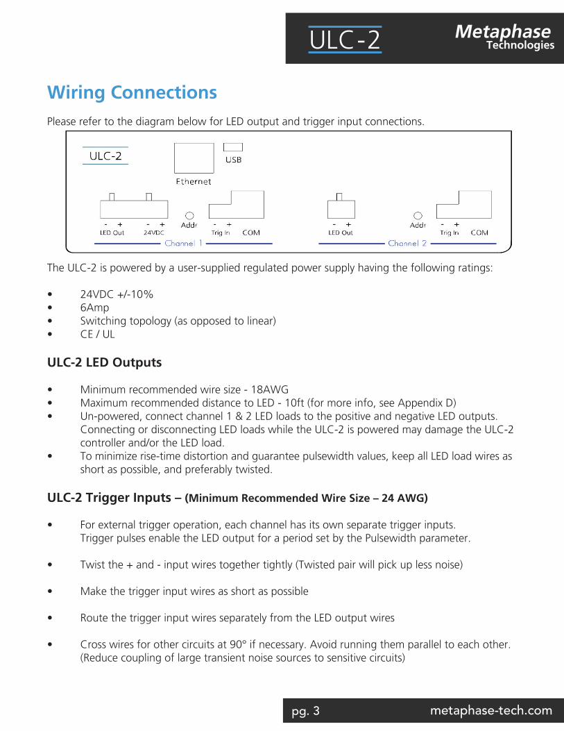
Wiring ConnectionsPlease refer to the diagram below for LED output and trigger input connections.
The ULC-2 is powered by a user-supplied regulated power supply having the following ratings:
• 24VDC +/-10%• 6Amp • Switching topology (as opposed to linear) • CE / UL ULC-2 LED Outputs
• Minimum recommended wire size - 18AWG• Maximum recommended distance to LED - 10ft (for more info, see Appendix D)• Un-powered, connect channel 1 & 2 LED loads to the positive and negative LED outputs. Connecting or disconnecting LED loads while the ULC-2 is powered may damage the ULC-2 controller and/or the LED load.• To minimize rise-time distortion and guarantee pulsewidth values, keep all LED load wires as short as possible, and preferably twisted.
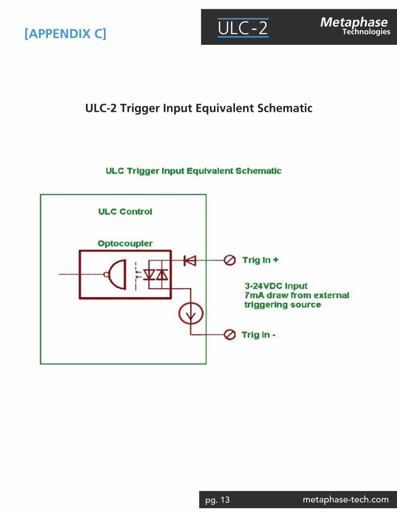
ULC-2 Trigger Inputs – (Minimum Recommended Wire Size – 24 AWG)
• For external trigger operation, each channel has its own separate trigger inputs. Trigger pulses enable the LED output for a period set by the Pulsewidth parameter.
• Twist the + and - input wires together tightly (Twisted pair will pick up less noise)
• Make the trigger input wires as short as possible
• Route the trigger input wires separately from the LED output wires
• Cross wires for other circuits at 90° if necessary. Avoid running them parallel to each other. (Reduce coupling of large transient noise sources to sensitive circuits)
pg. 4 metaphase-tech.com
MetaphaseTechnologiesULC-2
Quick StartFollow the steps below to quickly setup the Metaphase ULC-2 for basic operation using the ULC-2 keypad:
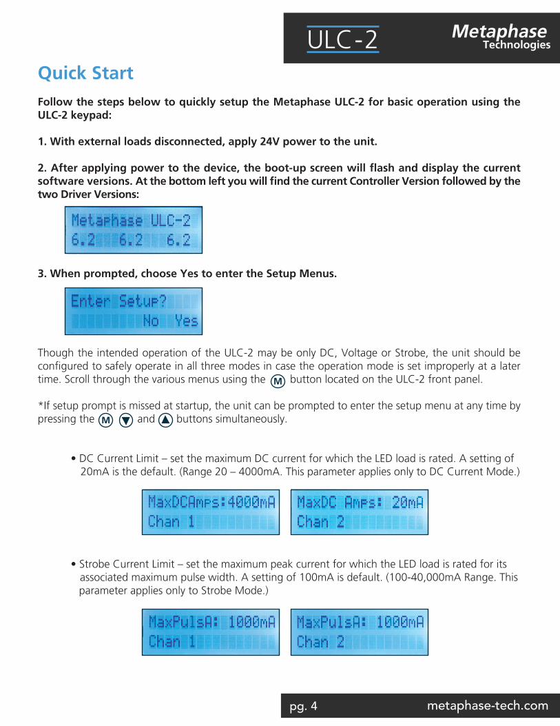
1. With external loads disconnected, apply 24V power to the unit. 2. After applying power to the device, the boot-up screen will flash and display the current software versions. At the bottom left you will find the current Controller Version followed by the two Driver Versions:
3. When prompted, choose Yes to enter the Setup Menus.
Though the intended operation of the ULC-2 may be only DC, Voltage or Strobe, the unit should be configured to safely operate in all three modes in case the operation mode is set improperly at a later time. Scroll through the various menus using the button located on the ULC-2 front panel.
*If setup prompt is missed at startup, the unit can be prompted to enter the setup menu at any time by pressing the and buttons simultaneously.
• DC Current Limit – set the maximum DC current for which the LED load is rated. A setting of 20mA is the default. (Range 20 – 4000mA. This parameter applies only to DC Current Mode.)
• Strobe Current Limit – set the maximum peak current for which the LED load is rated for its associated maximum pulse width. A setting of 100mA is default. (100-40,000mA Range. This parameter applies only to Strobe Mode.)
M
M
pg. 5 metaphase-tech.com
MetaphaseTechnologiesULC-2
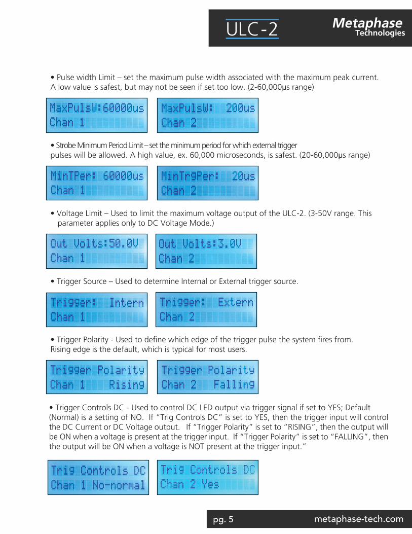
• Pulse width Limit – set the maximum pulse width associated with the maximum peak current. A low value is safest, but may not be seen if set too low. (2-60,000µs range)
• Strobe Minimum Period Limit – set the minimum period for which external trigger pulses will be allowed. A high value, ex. 60,000 microseconds, is safest. (20-60,000µs range)
• Voltage Limit – Used to limit the maximum voltage output of the ULC-2. (3-50V range. This parameter applies only to DC Voltage Mode.)
• Trigger Source – Used to determine Internal or External trigger source.
• Trigger Polarity - Used to define which edge of the trigger pulse the system fires from. Rising edge is the default, which is typical for most users.
• Trigger Controls DC - Used to control DC LED output via trigger signal if set to YES; Default (Normal) is a setting of NO. If “Trig Controls DC” is set to YES, then the trigger input will control the DC Current or DC Voltage output. If “Trigger Polarity” is set to “RISING”, then the output will be ON when a voltage is present at the trigger input. If “Trigger Polarity” is set to “FALLING”, then the output will be ON when a voltage is NOT present at the trigger input.”
pg. 6 metaphase-tech.com
MetaphaseTechnologiesULC-2
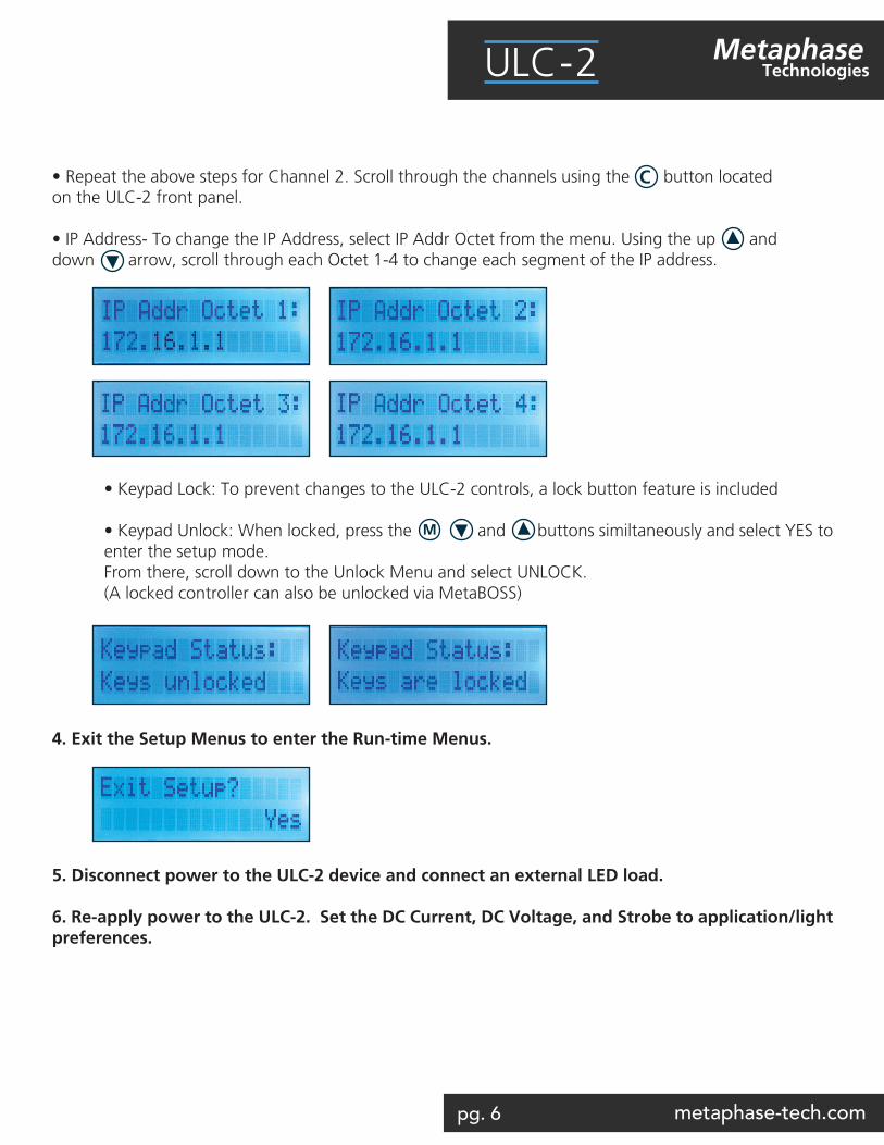
• Repeat the above steps for Channel 2. Scroll through the channels using the button located on the ULC-2 front panel.
• IP Address- To change the IP Address, select IP Addr Octet from the menu. Using the up and down arrow, scroll through each Octet 1-4 to change each segment of the IP address.
• Keypad Lock: To prevent changes to the ULC-2 controls, a lock button feature is included • Keypad Unlock: When locked, press the and buttons similtaneously and select YES to enter the setup mode. From there, scroll down to the Unlock Menu and select UNLOCK. (A locked controller can also be unlocked via MetaBOSS)
4. Exit the Setup Menus to enter the Run-time Menus.
5. Disconnect power to the ULC-2 device and connect an external LED load.
6. Re-apply power to the ULC-2. Set the DC Current, DC Voltage, and Strobe to application/light preferences.
M
C
pg. 7 metaphase-tech.com
MetaphaseTechnologiesULC-2
User-interface Menus
A. Setup Menus
The setup menus below appear only when the ULC-2 is powered on. Each menu described below ap-plies to two channels independently. The menus include:
Trigger Source (Internal or External)
This menu allows the setting of the source of trigger when in Strobe mode. In normal operation, Exter-nal trigger is selected, but for setup and testing purposes, users may elect to use internal trigger in an effort to verify wiring connections and operation.
When set to External trigger, the ULC-2 will ignore external trigger input events received faster than what is set by Strobe Minimum Period.
For Internal trigger, the frequency of the strobing output is set by Strobe Minimum Period. For both types of trigger, the output Strobe Pulsewidth is determined by the Strobe Pulsewidth parameter.
Continuous (DC) Current Limit
This “Limit” menu provides the user a way to set the upper bound of the LED output DC Current up to 4 A current found in the “Run time” menus. For example, if the DC Current Limit is set to 1.6 Amps, the DC current can be adjusted from 20mA to 1.6 Amps. Such a limit assures adjustments never exceed the limits of the LED load.
Voltage (DC) Limit
This “Limit” menu provides the user a way to set the upper bound of the LED output DC Voltage (found in the Runtime menu) between 3 and 50 volts. For example, if the DC Voltage Limit is set to 24 volts, the DC Voltage can be adjusted from 3 volts 24 volts. Such a limit assures adjustments never exceed the limits of the LED load.
Strobe (Pulse) Current Limit
This “Limit” menu provides the user a way to set the upper bound of the LED output Strobe current up to 40 amps found in the “Run time” menus. For example, if the Strobe Current Limit is set to 9 Amps, the Strobe current can be adjusted from 100mA to 9 Amps. Such a limit assures adjustments never ex-ceed the limits of the LED load.
Strobe Pulsewidth Limit
This “Limit” menu provides the user a way to set the maximum LED output Strobe Pulsewidth found in the “Run time” menus. For example, if the Strobe Pulsewidth Limit is set to 100 microseconds, the Strobe Pulsewidth can be adjusted from 2 to 100 microseconds. Such a limit assures adjustments never exceed the limit of the LED load.
pg. 8 metaphase-tech.com
MetaphaseTechnologiesULC-2
User-interface Menus
Strobe Minimum Period Limit
This “Limit” menu provides the user a way to set the Minimum Period of the external strobe triggers found in the “Runtime” menus. For example, if the Minimum Period Limit is set to 100 microseconds, the Minimum Period can be adjusted from a maximum of 60 milliseconds down to a minimum of 100 microseconds. Such a limit assures adjustments never exceed the limits of the LED load.
Restore to Default
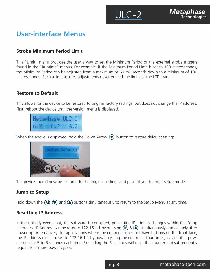
This allows for the device to be restored to original factory settings, but does not change the IP address. First, reboot the device until the version menu is displayed.
When the above is displayed, hold the Down Arrow button to restore default settings.
The device should now be restored to the original settings and prompt you to enter setup mode.
Jump to Setup
Hold down the and buttons simultaneously to return to the Setup Menu at any time.
Resetting IP Address
In the unlikely event that, the software is corrupted, preventing IP address changes within the Setup menu, the IP Address can be reset to 172.16.1.1 by pressing & simultaneously immediately after power up. Alternatively, for applications where the controller does not have buttons on the front face, the IP address can be reset to 172.16.1.1 by power cycling the controller four times, leaving it in pow-ered on for 5 to 6 seconds each time. Exceeding the 6 seconds will reset the counter and subsequently require four more power cycles.
M
M
pg. 9 metaphase-tech.com
MetaphaseTechnologiesULC-2
Runtime MenusThese menus are shown after the setup menus. Each menu described below applies to two channels independently. The menus include:
Mode
The Mode menu controls whether the ULC-2 output is continuous DC current, DC voltage, or Strobed.
DC Current
The DC current menu controls the ULC-2 output from 20mA to the DC Current Limit value set in the Setup menus.
DC Voltage
The DC Voltage menu controls the ULC-2 output from 3V to the Voltage DC Limit value set in the Setup menus.
Strobe Pulse Current
The Pulse current menu controls the ULC-2 output from .1 Amps to the Pulse Current Limit value set in the Setup menus. This menu applies only to the output when the mode is set to Strobe.
Strobe Pulsewidth
The Strobe Pulsewidth menu controls the ULC-2 output from 2 microseconds to the Strobe Pulsewidth Limit value set in the Setup menus. This menu applies only to the output when the mode is set to Strobe. Strobe Minimum Period
The Strobe Minimum Period menu controls the ULC-2 output from 60 msec down to the minimum value set by Strobe Minimum Period Limit value set in the Setup menus. This menu applies only to the output when the mode is set to Strobe. The ULC-2 controller ignores trigger inputs faster than the Strobe Minimum Period.
pg. 10 metaphase-tech.com
MetaphaseTechnologiesULC-2
Runtime Menus
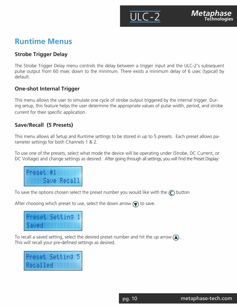
Strobe Trigger Delay
The Strobe Trigger Delay menu controls the delay between a trigger input and the ULC-2’s subsequent pulse output from 60 msec down to the minimum. There exists a minimum delay of 6 usec (typical) by default.
One-shot Internal Trigger
This menu allows the user to simulate one cycle of strobe output triggered by the internal trigger. Dur-ing setup, this feature helps the user determine the appropriate values of pulse width, period, and strobe current for their specific application.
Save/Recall (5 Presets)
This menu allows all Setup and Runtime settings to be stored in up to 5 presets. Each preset allows pa-rameter settings for both Channels 1 & 2.
To use one of the presets, select what mode the device will be operating under (Strobe, DC Current, or DC Voltage) and change settings as desired. After going through all settings, you will find the Preset Display:
To save the options chosen select the preset number you would like with the button
After choosing which preset to use, select the down arrow to save.
To recall a saved setting, select the desired preset number and hit the up arrow . This will recall your pre-defined settings as desired.
C
pg. 11 metaphase-tech.com
MetaphaseTechnologiesULC-2
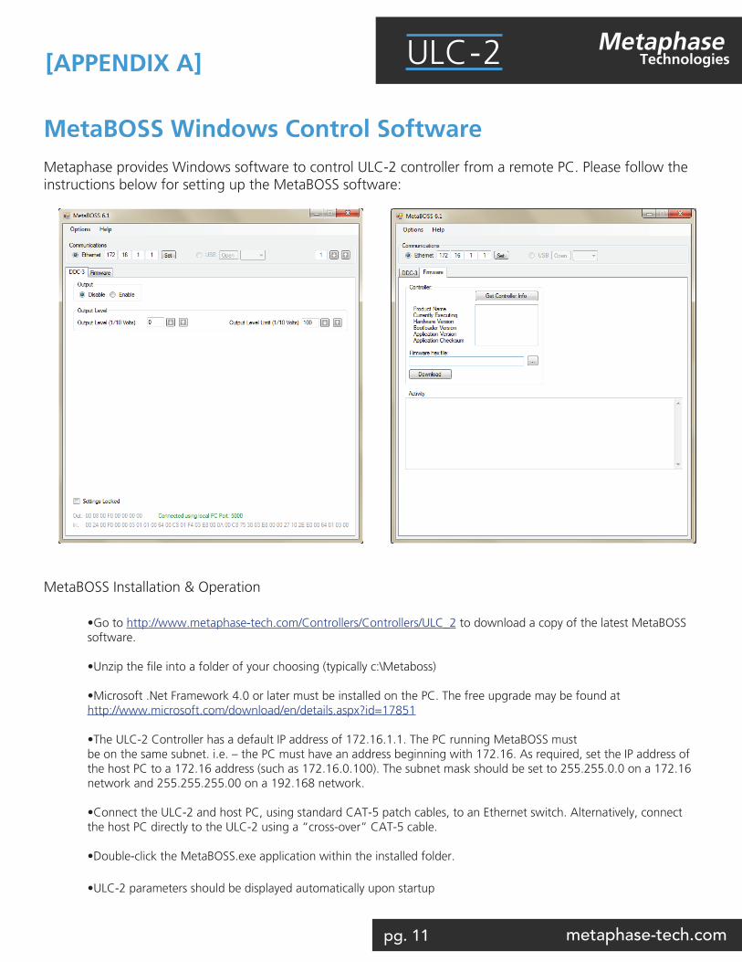
MetaBOSS Windows Control SoftwareMetaphase provides Windows software to control ULC-2 controller from a remote PC. Please follow the instructions below for setting up the MetaBOSS software:
MetaBOSS Installation & Operation
•Go to http://www.metaphase-tech.com/Controllers/Controllers/ULC_2 to download a copy of the latest MetaBOSS software.
•Unzip the file into a folder of your choosing (typically c:\Metaboss)
•Microsoft .Net Framework 4.0 or later must be installed on the PC. The free upgrade may be found at http://www.microsoft.com/download/en/details.aspx?id=17851
•The ULC-2 Controller has a default IP address of 172.16.1.1. The PC running MetaBOSS must be on the same subnet. i.e. – the PC must have an address beginning with 172.16. As required, set the IP address of the host PC to a 172.16 address (such as 172.16.0.100). The subnet mask should be set to 255.255.0.0 on a 172.16 network and 255.255.255.00 on a 192.168 network. •Connect the ULC-2 and host PC, using standard CAT-5 patch cables, to an Ethernet switch. Alternatively, connect the host PC directly to the ULC-2 using a “cross-over” CAT-5 cable. •Double-click the MetaBOSS.exe application within the installed folder.
•ULC-2 parameters should be displayed automatically upon startup
[APPENDIX A]
pg. 12 metaphase-tech.com
MetaphaseTechnologiesULC-2
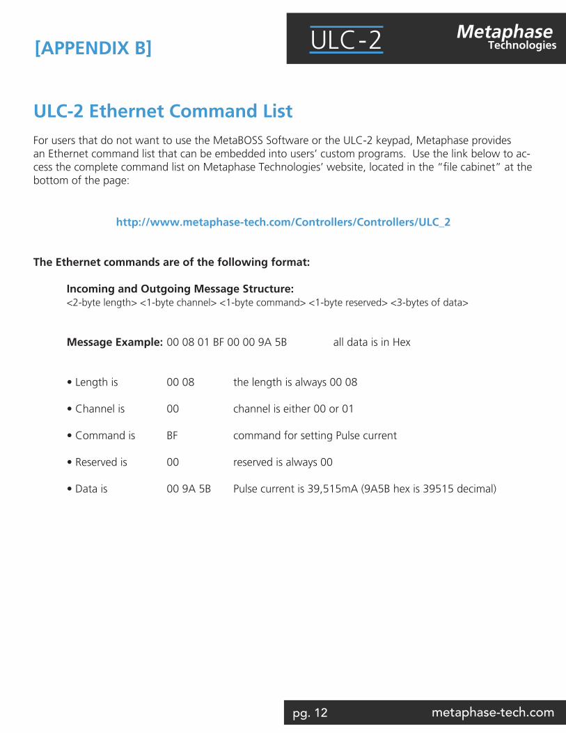
ULC-2 Ethernet Command ListFor users that do not want to use the MetaBOSS Software or the ULC-2 keypad, Metaphase provides an Ethernet command list that can be embedded into users’ custom programs. Use the link below to ac-cess the complete command list on Metaphase Technologies’ website, located in the “file cabinet” at the bottom of the page:
http://www.metaphase-tech.com/Controllers/Controllers/ULC_2
The Ethernet commands are of the following format: Incoming and Outgoing Message Structure: <2-byte length> <1-byte channel> <1-byte command> <1-byte reserved> <3-bytes of data> Message Example: 00 08 01 BF 00 00 9A 5B all data is in Hex
• Length is 00 08 the length is always 00 08 • Channel is 00 channel is either 00 or 01 • Command is BF command for setting Pulse current • Reserved is 00 reserved is always 00 • Data is 00 9A 5B Pulse current is 39,515mA (9A5B hex is 39515 decimal)
[APPENDIX B]
pg. 13 metaphase-tech.com
MetaphaseTechnologiesULC-2
ULC-2 Trigger Input Equivalent Schematic
[APPENDIX C]
pg. 14 metaphase-tech.com
MetaphaseTechnologiesULC-2
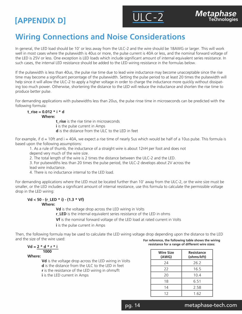
Wiring Connections and Noise ConsiderationsIn general, the LED load should be 10’ or less away from the ULC-2 and the wire should be 18AWG or larger. This will work well in most cases where the pulsewidth is 40us or more, the pulse current is 40A or less, and the nominal forward voltage of the LED is 25V or less. One exception is LED loads which include significant amount of internal equivalent series resistance. In such cases, the internal LED resistance should be added to the LED wiring resistance in the formulas below.
If the pulsewidth is less than 40us, the pulse rise time due to lead wire inductance may become unacceptable since the rise time may become a significant percentage of the pulsewidth. Setting the pulse period to at least 20 times the pulsewidth will help since it will allow the ULC-2 to apply a higher voltage in order to charge the inductance more quickly without dissipat-ing too much power. Otherwise, shortening the distance to the LED will reduce the inductance and shorten the rise time to produce better pulse.
For demanding applications with pulsewidths less than 20us, the pulse rinse time in microseconds can be predicted with the following formula:
For example, if d = 10ft and i = 40A, we expect a rise time of nearly 5us which would be half of a 10us pulse. This formula is based upon the following assumptions: 1. As a rule of thumb, the inductance of a straight wire is about 12nH per foot and does not depend very much of the wire size. 2. The total length of the wire is 2 times the distance between the ULC-2 and the LED. 3. For pulsewidths less than 20 times the pulse period, the ULC-2 develops about 2V across the lead wire inductance. 4. There is no inductance internal to the LED load.
For demanding applications where the LED must be located further than 10’ away from the ULC-2, or the wire size must be smaller, or the LED includes a significant amount of internal resistance, use this formula to calculate the permissible voltage drop in the LED wiring:
Then, the following formula may be used to calculate the LED wiring voltage drop depending upon the distance to the LED and the size of the wire used:
t_rise = 0.012 * i * d Where: t_rise is the rise time in microseconds i is the pulse current in Amps d is the distance from the ULC to the LED in feet
Vd < 50 - (r_LED * i) - (1.3 * Vf) Where: Vd is the voltage drop across the LED wiring in Volts r_LED is the internal equivalent series resistance of the LED in ohms Vf is the nominal forward voltage of the LED load at rated current in Volts i is the pulse current in Amps
Vd = 2 * d * r * i 1000Where: Vd is the voltage drop across the LED wiring in Volts d is the distance from the ULC to the LED in feet r is the resistance of the LED wiring in ohms/ft i is the LED current in Amps
For reference, the following table shows the wiring resistance for a range of different wire sizes:
Wire Size (AWG)
Resistance (ohms/kft)
24 26.2
22 16.5
20 10.4
18 6.51
14 2.58
12 1.62
[APPENDIX D]
pg. 15 metaphase-tech.com
MetaphaseTechnologiesULC-2
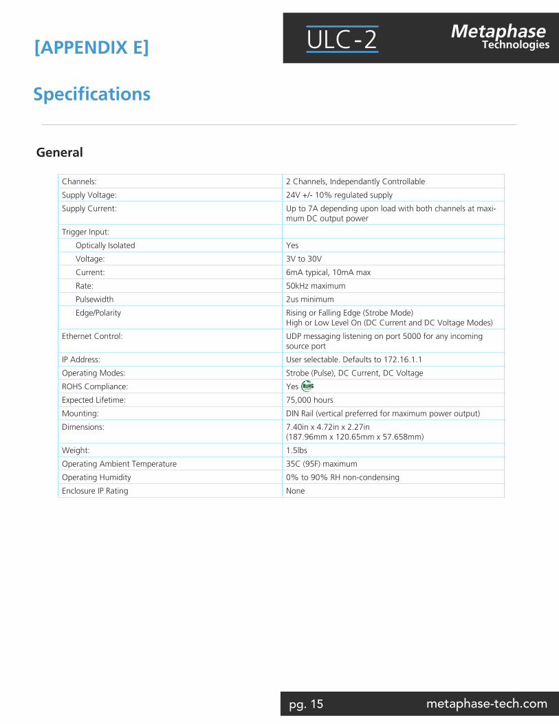
Specifications
General
[APPENDIX E]
Channels: 2 Channels, Independantly Controllable
Supply Voltage: 24V +/- 10% regulated supply
Supply Current: Up to 7A depending upon load with both channels at maxi-mum DC output power
Trigger Input:
Optically Isolated Yes
Voltage: 3V to 30V
Current: 6mA typical, 10mA max
Rate: 50kHz maximum
Pulsewidth 2us minimum
Edge/Polarity Rising or Falling Edge (Strobe Mode)High or Low Level On (DC Current and DC Voltage Modes)
Ethernet Control: UDP messaging listening on port 5000 for any incoming source port
IP Address: User selectable. Defaults to 172.16.1.1
Operating Modes: Strobe (Pulse), DC Current, DC Voltage
ROHS Compliance: Yes
Expected Lifetime: 75,000 hours
Mounting: DIN Rail (vertical preferred for maximum power output)
Dimensions: 7.40in x 4.72in x 2.27in(187.96mm x 120.65mm x 57.658mm)
Weight: 1.5lbs
Operating Ambient Temperature 35C (95F) maximum
Operating Humidity 0% to 90% RH non-condensing
Enclosure IP Rating None
pg. 16 metaphase-tech.com
MetaphaseTechnologiesULC-2
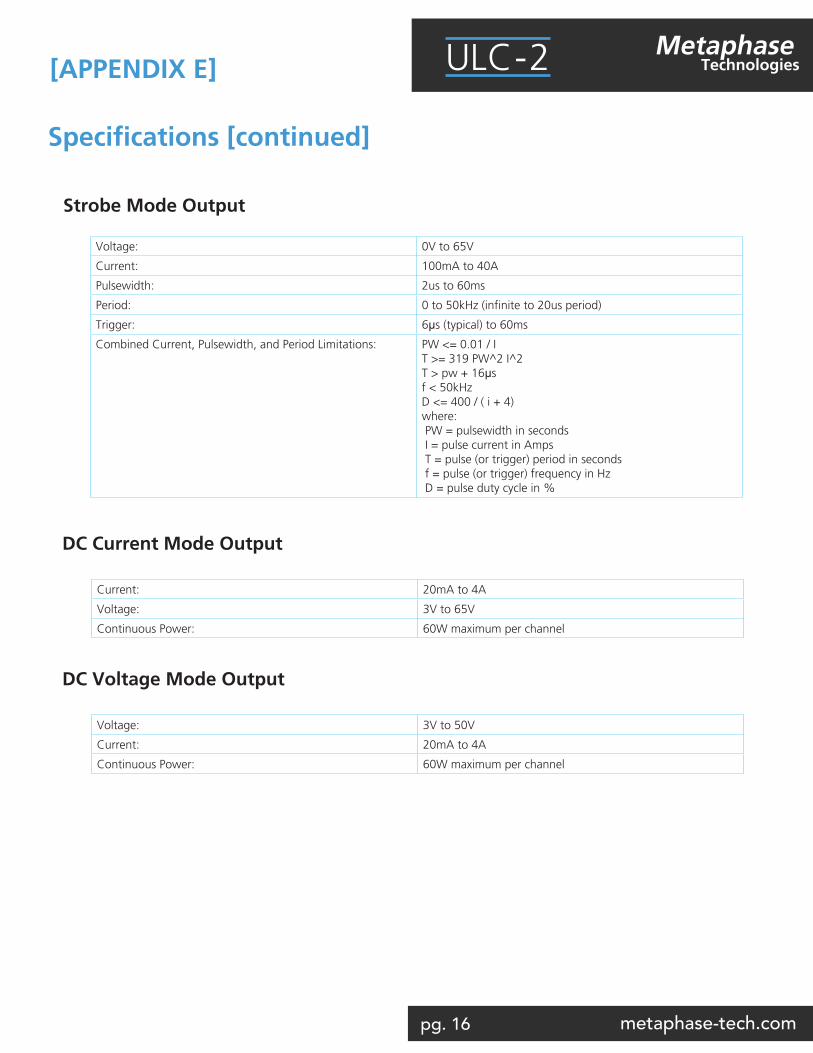
Current: 20mA to 4A
Voltage: 3V to 65V
Continuous Power: 60W maximum per channel
Voltage: 3V to 50V
Current: 20mA to 4A
Continuous Power: 60W maximum per channel
DC Current Mode Output
DC Voltage Mode Output
Specifications [continued]
[APPENDIX E]
Strobe Mode Output
Voltage: 0V to 65V
Current: 100mA to 40A
Pulsewidth: 2us to 60ms
Period: 0 to 50kHz (infinite to 20us period)
Trigger: 6µs (typical) to 60ms
Combined Current, Pulsewidth, and Period Limitations: PW <= 0.01 / IT >= 319 PW^2 I^2T > pw + 16µsf < 50kHzD <= 400 / ( i + 4)where: PW = pulsewidth in seconds I = pulse current in Amps T = pulse (or trigger) period in seconds f = pulse (or trigger) frequency in Hz D = pulse duty cycle in %
pg. 17 metaphase-tech.com
MetaphaseTechnologiesULC-2
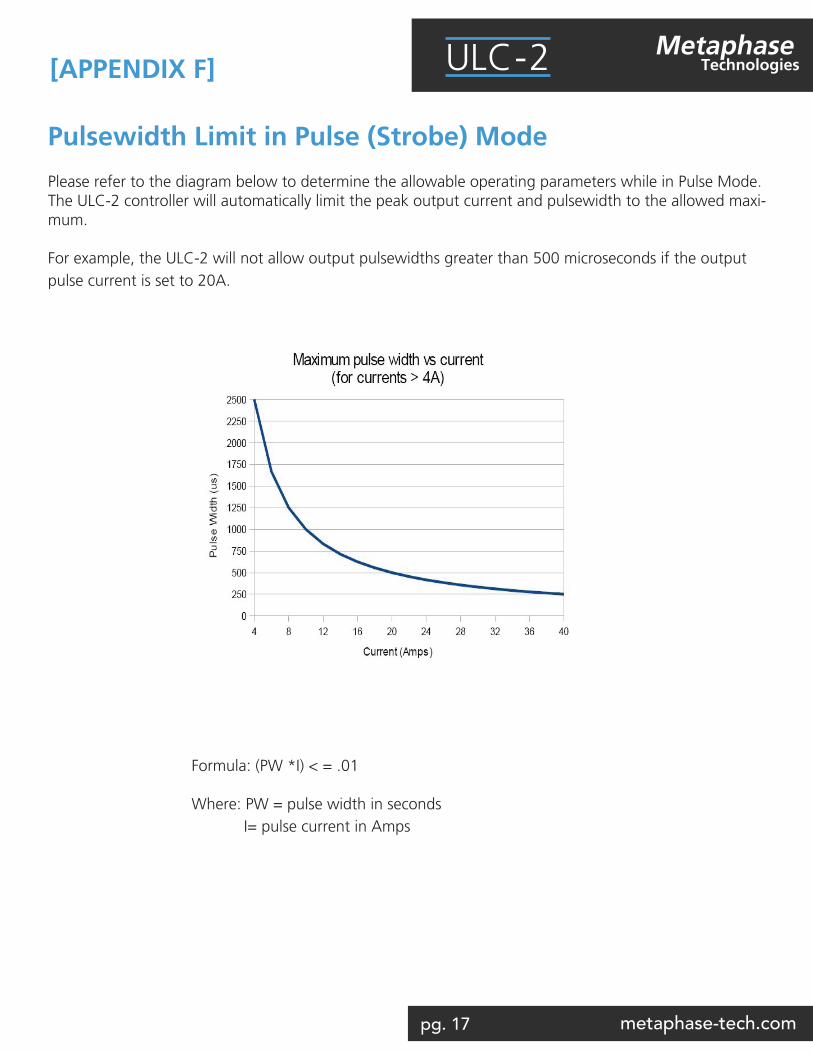
Pulsewidth Limit in Pulse (Strobe) Mode
Please refer to the diagram below to determine the allowable operating parameters while in Pulse Mode. The ULC-2 controller will automatically limit the peak output current and pulsewidth to the allowed maxi-mum.
For example, the ULC-2 will not allow output pulsewidths greater than 500 microseconds if the output pulse current is set to 20A.
Formula: (PW *I) < = .01
Where: PW = pulse width in seconds I= pulse current in Amps
[APPENDIX F]
pg. 18 metaphase-tech.com
MetaphaseTechnologiesULC-2
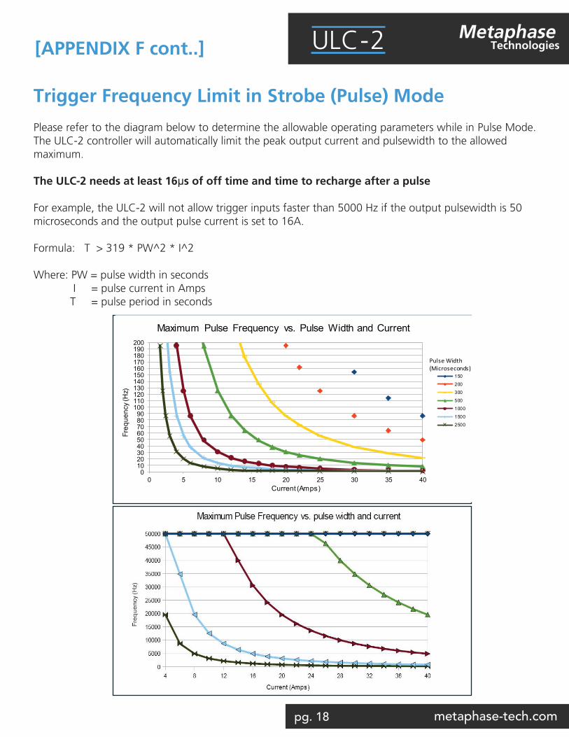
Trigger Frequency Limit in Strobe (Pulse) Mode
Please refer to the diagram below to determine the allowable operating parameters while in Pulse Mode. The ULC-2 controller will automatically limit the peak output current and pulsewidth to the allowed maximum.
The ULC-2 needs at least 16µs of off time and time to recharge after a pulse
For example, the ULC-2 will not allow trigger inputs faster than 5000 Hz if the output pulsewidth is 50 microseconds and the output pulse current is set to 16A.
Formula: T > 319 * PW^2 * I^2 Where: PW = pulse width in seconds I = pulse current in Amps T = pulse period in seconds
0102030405060708090
100110120130140150160170180190200
0 5 10 15 20 25 30 35 40
Freq
uenc
y (H
z)
Current (Amps)
Maximum Pulse Frequency vs. Pulse Width and Current
150
200
300
500
1000
1500
2500
Pulse Width (Microseconds)
[APPENDIX F cont..]
pg. 19 metaphase-tech.com
MetaphaseTechnologiesULC-2
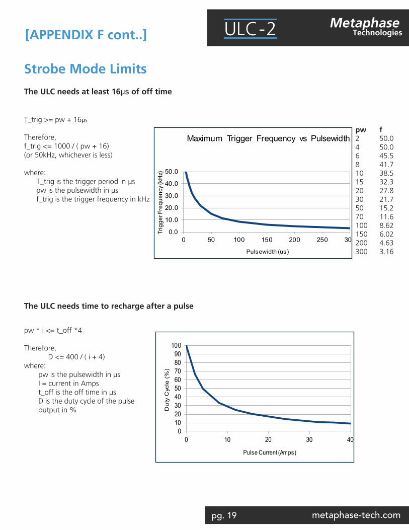
Strobe Mode Limits
The ULC needs at least 16µs of off time
0.0
10.0
20.0
30.0
40.0
50.0
0 50 100 150 200 250 300
Trig
ger F
requ
ency
(kH
z)
Pulsewidth (us)
Maximum Trigger Frequency vs Pulsewidth
0102030405060708090
100
0 10 20 30 40
Du
ty C
ycle
(%
)
Pulse Current (Amps)
Maximum Duty Cycle vs. Pulse Current
T_trig >= pw + 16µs
Therefore, f_trig <= 1000 / ( pw + 16) (or 50kHz, whichever is less)
where: T_trig is the trigger period in µs pw is the pulsewidth in µs f_trig is the trigger frequency in kHz
pw * i <= t_off *4
Therefore, D <= 400 / ( i + 4) where: pw is the pulsewidth in µs I = current in Amps t_off is the off time in µs D is the duty cycle of the pulse output in %
pw f2 50.04 50.06 45.58 41.710 38.515 32.320 27.830 21.750 15.270 11.6100 8.62150 6.02200 4.63300 3.16
The ULC needs time to recharge after a pulse
[APPENDIX F cont..]
pg. 20 metaphase-tech.com
MetaphaseTechnologiesULC-2
ULC-2Metaphase Technologiesmetaphase-tech.com
addr 3412 Progress Drive, Unit C Bensalem PA, 19020 - USAph 215.639.8699fax 215.639.0877em [email protected]