uk 4-series user manual 1498751 41 en 4-iien.pdf · • do not operate the unit in an environment...
TRANSCRIPT

4-Series
Operating Instructions

Copyright: Enraf-Nonius B.V. P.O. Box 12080 Vareseweg 127 3004 GB Rotterdam The Netherlands Tel: +31 (0)10 – 20 30 600 Fax: +31 (0)10 – 20 30 699 [email protected] www.enraf-nonius.com Part number: 1498751_41 October 31, 2013


2
TABLE OF CONTENTS
1 Foreword ....................................................................................................................................... 4 1.1 Intended User/Operator ....................................................................................................... 4 1.2 Product Liability .................................................................................................................... 4
2 Product Description ..................................................................................................................... 4
3 Precautionary Instructions ......................................................................................................... 5
4 Intended Use................................................................................................................................. 6 4.1 Intended Use Electrotherapy ............................................................................................... 6
4.1.1 Pain Management ....................................................................................................................... 6 4.1.2 Muscle Stimulation ...................................................................................................................... 6 4.1.3 Description Current Waveforms .................................................................................................. 8 4.1.4 Illustrations Current Waveforms ................................................................................................ 16
4.2 Intended Use Ultrasound therapy ...................................................................................... 21 4.2.1 Indications Ultrasound .............................................................................................................. 21 4.2.2 Contra-indications Ultrasound ................................................................................................... 21 4.2.3 Precautions and Warnings Ultrasound ..................................................................................... 21 4.2.4 Relevant Hazards Ultrasound ................................................................................................... 21 4.2.5 Potential Adverse Effects Ultrasound ....................................................................................... 22 4.2.6 Parameters ultrasound therapy ................................................................................................. 22
4.3 Combination Therapy ......................................................................................................... 22
5 Package Contents ...................................................................................................................... 22
6 Installation .................................................................................................................................. 23 6.1 Systems without a Vacotron .............................................................................................. 23 6.2 Systems with a Vacotron ................................................................................................... 23 6.3 Connection to mains supply ............................................................................................... 23 6.4 Disconnection from mains supply ...................................................................................... 24 6.5 Placing the optional battery ................................................................................................ 24 6.6 Operation from battery ....................................................................................................... 24
7 Application Information ............................................................................................................. 25 7.1 Electrotherapy .................................................................................................................... 25
7.1.1 Before treatment ....................................................................................................................... 25 7.1.2 Flexible rubber electrodes ........................................................................................................ 25 7.1.3 Vacuum electrodes ................................................................................................................... 26 7.1.4 Self-adhesive electrodes .......................................................................................................... 26 7.1.5 Electrolytic effects ..................................................................................................................... 26 7.1.6 Current density ......................................................................................................................... 26 7.1.7 Connection and disconnection reactions .................................................................................. 26
7.2 Ultrasound .......................................................................................................................... 27 7.2.1 Contact Control ......................................................................................................................... 27 7.2.2 The contact medium ................................................................................................................. 27 7.2.3 Before treatment ....................................................................................................................... 27 7.2.4 During treatment ....................................................................................................................... 27 7.2.5 After treatment .......................................................................................................................... 27
7.3 Vacuum .............................................................................................................................. 27
8 Operating Instructions .............................................................................................................. 28 8.1 Operator Controls............................................................................................................... 28 8.2 Basic Operation .................................................................................................................. 30
8.2.1 Device turn on ........................................................................................................................... 30 8.2.2 Display Organization ................................................................................................................. 30 8.2.3 Navigation ................................................................................................................................. 31 8.2.4 Shutting device down ................................................................................................................ 39 8.2.5 Operating Details ...................................................................................................................... 39
9 Maintenance and Troubleshooting .......................................................................................... 41 9.1 Cleaning and Disinfection .................................................................................................. 41
9.1.1 Cleaning of apparatus ............................................................................................................... 41 9.1.2 Cleaning display panel .............................................................................................................. 41 9.1.3 Electrodes and accessories ...................................................................................................... 41 9.1.4 Patient cable ............................................................................................................................. 41 9.1.5 Ultrasound applicator ................................................................................................................ 41 9.1.6 Vacuum electrodes and sponges .............................................................................................. 42 9.1.7 Vacuum cables ......................................................................................................................... 42 9.1.8 Cleaning the water reservoir and hoses: .................................................................................. 42
9.2 Warning Messages, Error Messages and Troubleshooting .............................................. 42 9.2.1 Error code ................................................................................................................................. 42

3
9.2.2 Patient Circuit Interrupted ......................................................................................................... 42 9.2.3 Battery Low ............................................................................................................................... 42 9.2.4 Water Reservoir Full ................................................................................................................. 43 9.2.5 Vacuum Leak ............................................................................................................................ 43 9.2.6 Ultrasound Applicator Error ...................................................................................................... 43 9.2.7 Insufficient DC Supply .............................................................................................................. 43
9.3 User Maintenance ............................................................................................................. 43 9.3.1 Optimize Contact Control Ultrasound Applicator ...................................................................... 43 9.3.2 Back-up and Restore Favorites ................................................................................................ 43 9.3.3 Firmware Update ...................................................................................................................... 44
9.4 Technical Maintenance ..................................................................................................... 44 9.5 End of life ........................................................................................................................... 44
10 Specifications ............................................................................................................................ 45 10.1 Ultrasound parameters .................................................................................................. 45 10.2 Stimulator output parameters ........................................................................................ 46 10.3 Technical Data ............................................................................................................... 49 10.4 Safety and Performance standards ............................................................................... 50 10.5 EMC details .................................................................................................................... 50
11 Ordering information ................................................................................................................ 53

4
1 Foreword 1.1 Intended User/Operator This manual has been written for the owners and operators of the 4-series. It contains general instructions on operation, precautionary practices, maintenance and parts information. In order to maximize the use, efficiency and lifespan of your unit, please read this manual thoroughly and become familiar with the controls as well as the accessories before operating the unit. This device is designed to only be used by or under the supervision of persons using the medical device in the course of their work and in the framework of a professional healthcare activity, who understand the benefits and limitations of electrotherapy and ultrasound therapy. I.e.“professional users”. WARNING (USA only): The 4-series are prescription devices that should only be used under the supervision or by the order of a physician or other licensed healthcare provider. Specifications put forth in this manual were in effect at the time of publication. However, owing to Enraf-Nonius her policy of continual improvement, changes to these specifications may be made at any time without obligation on the part of Enraf-Nonius. 1.2 Product Liability A law on Product Liability has become effective in many countries. This Product Liability law implies, amongst other things, that once a period of 10 years has elapsed after a product has been brought into circulation, the manufacturer can no longer be held responsible for possible shortcomings of the product. To the maximum extent permitted by applicable law, in no event will Enraf-Nonius or its suppliers or resellers be liable for any indirect, special, incidental or consequential damages arising from the use of or inability to use the product, including, without limitation, damages for loss of goodwill, work and productivity, computer failure or malfunction, or any and all other commercial damages or losses, even if advised of the possibility thereof, and regardless of the legal or equitable theory (contract, tort or otherwise) upon which the claim is based. In any case, Enraf-Nonius’s entire liability under any provision of this agreement shall not exceed in the aggregate the sum of the fees paid for this product and fees for support of the product received by Enraf-Nonius under a separate support agreement (if any), with the exception of death or personal injury caused by the negligence of Enraf-Nonius to the extent applicable law prohibits the limitation of damages in such cases. Enraf-Nonius cannot be held liable for any consequence resulting from incorrect information provided by its personnel, or errors incorporated in this manual and / or other accompanying documentation (including commercial documentation) The opposing party (product’s user or its representative) shall disclaim Enraf-Nonius from all claims arising from third parties, whatever nature or whatever relationship to the opposing party.
2 Product Description The 4-series is a family of products for physical therapy. The devices share an identical control panel equipped with a full colour touch panel. The devices are mains powered and can optionally be equipped with a battery for mains independent operation. The family comprises the products described below. Endomed 482: The Endomed 482 is equipped with two completely identical electrotherapy channels. The electrotherapy channels can be used in combination (linked) or totally independent. A comprehensive set of current waveforms is available, targeting both pain management and muscle stimulation applications. Protocol driven operation is available, providing both factory or user defined sequences of treatment steps. Protocols can run on linked or independent channels. With independent channels two different protocols can be performed simultaneously. Sonopuls 490: The Sonopuls 490 is an ultrasound therapy device. The device provides two positions for attachment of an ultrasound applicator. Depending on the device configuration ordered, the Sonopuls 490 comes with

5
an applicator with a large contact area, an applicator with a small contact area or with both applicators. The applicators can operate in continuous or pulsed mode at an ultrasound frequency of 1 MHz or 3 MHz. Contact control suspends the application of ultrasonic energy when acoustical contact with the treatment area becomes insufficient. The applicators are suitable for subaqual treatments. Sonopuls 492: The Sonopuls 492 is a combination device, combining the functions of the Endomed 482 and the Sonopuls 490 in a single device. With the Sonopuls 492 the simultaneous application of ultrasound and electrotherapy (combination therapy) is also possible. The remaining electrotherapy channel can then be used independently. Vacotron 460: Electrotherapy can be applied through standard or vacuum electrodes. With vacuum electrodes the Vacotron 460 generates the vacuum through which the vacuum electrodes are attached to the patient. The device is placed beneath the Endomed 482 or Sonopuls 492, from which its power is derived and through which it is also operated.
3 Precautionary Instructions In this section general Warnings and Precautions are listed, that you should be aware of when using the 4-series. See also chapter 4.1 for Warnings and Precautions that are application specific. WARNING:
• Federal law (USA only) restricts this device to sale by, or on the order of, a physician or licensed practitioner. This device should be used only under the continued supervision of a physician or licensed practitioner.
• Make certain that the unit is electrically grounded by connecting only to a grounded electrical service receptacle conforming to the applicable national and local electrical codes.
• Do not operate the unit in an environment of short-wave or micro-wave diathermy. • This 4-series is not suitable for use in the presence of flammable anesthetics mixture with air,
oxygen, or nitrous oxide. • This device should be kept out of the reach of children.
CAUTION:
• Read, understand and practice the precautionary and operating instructions. Know the limitations and hazards associated with using any electrical stimulation device. Observe the precautionary and operational stickers placed on the unit.
• Use of controls or adjustments or performance of procedures other than those specified herein may result in hazardous exposure to ultrasonic energy.
• Handle the ultrasound applicator with care. Inappropriate handling of the ultrasound applicator may adversely affect its characteristics.
• Inspect the ultrasound applicator for cracks which may allow the ingress of conductive fluid before each use.
• Inspect ultrasound applicator cables and associated connectors before each use. • Do not operate the 4-series when connected to any unit other than Enraf-Nonius BV devices. • This unit should be operated in temperatures between 10 °C and 40 °C (50 °F and 104 °F), with
a Relative Humidity ranging from 20%-90% non condensing. • Do not expose the unit to direct sunlight, heat radiated from a heat radiator, excessive amounts of
dust, moisture, vibrations and mechanical shocks. • In the case of ingress of liquids, unplug the unit from the mains supply and have it checked by an
authorized person (see the paragraph on maintenance). • Before administering any treatment to a patient you should become acquainted with the operating
procedures for each mode of treatment available, as well as the indications, contra-indications, warnings and precautions. Consult other resources for additional information regarding the application of electrotherapy and ultrasound therapy.

6
4 Intended Use The device is designed to only be used by or under the supervision of persons using the medical device in the course of their work and in the framework of a professional healthcare activity, who understand the benefits and limitations of electrotherapy and ultrasound therapy. I.e.“professional users”. 4.1 Intended Use Electrotherapy
4.1.1 Pain Management
Pain Management is the use of electrical stimulation for pain relief. 4.1.1.1 Indications Pain Management
• Symptomatic relief of chronic, intractable pain. Management of pain associated with post-traumatic or postoperative conditions.
4.1.1.2 Contra-indications Pain Management
• This device should not be used for symptomatic pain relief unless etiology is established or unless a pain syndrome has been diagnosed.
• This device should not be used on patients with demand-type cardiac pacemakers. • This device should not be used over cancerous lesions. • Electrode placements that apply current to the carotid sinus region (anterior neck) must be
avoided. • Electrode placements that apply current transcerebrally (through the head) must be avoided. • Electrode placements that apply current transthoracically (the introduction of electrical current
into the heart may cause cardiac arrhythmias) must be avoided.
4.1.1.3 Warnings Pain Management • Benefits of TENS currents have not been established for pain of central origin. • This device is to be used as a symptomatic treatment for pain and has no curative value.
Patients should be cautioned and their activities regulated if pain that would otherwise serve as a protective mechanism is suppressed.
• The long-term effects of chronic electrical stimulation are unknown. • Safety has not been established for the use of therapeutic electrical stimulation during pregnancy. • Stimulation should not be applied over swollen, infected, or inflamed areas of skin eruptions e.g.,
phlebitis, thrombophlebitis, varicose veins, etc. • See also chapter 3, Precautionary Instructions, for general Warnings and Precautions.
4.1.1.4 Precautions Pain Management
• Isolated cases of skin rash may occur at the site of electrode placement following long-term applications. The irritation may be reduced by use of an alternate conductive medium or an alternative electrode placement.
• Effectiveness of this treatment is dependent upon patient selection. • See also chapter 3, Precautionary Instructions, for general Warnings and Precautions.
4.1.1.5 Adverse Effects Pain Management
• Skin irritation and burns beneath the electrodes have been reported with the use of therapeutic electrical stimulation.
4.1.1.6 Current Waveforms Pain Management
• For pain management the following current waveforms are recommended. 4.1.3.1, 4.1.3.2, 4.1.3.3, 4.1.3.5, 4.1.3.6, 4.1.3.7, 4.1.3.8, 4.1.3.9.2.
4.1.2 Muscle Stimulation
Muscle Stimulation is the use of electrical stimulation to treat muscle dysfunction.
7
4.1.2.1 Indications Muscle Stimulation • Relaxation of muscle spasms • Prevention or retardation of disuse atrophy • Increasing local blood circulation • Muscle re-education • Immediate post-surgical stimulation of calf muscles to prevent venous thrombosis • Maintaining or increasing range of motion • Dysphagia
4.1.2.2 Contra-indications Muscle Stimulation
• This device should not be used on patients with demand-type cardiac pacemakers • This device should not be used over cancerous lesions • Electrode placements that apply current to the sinus carotid region (anterior neck) must be
avoided (1 • Electrode placements that apply current transcerebrally (through the head) must be avoided. • Electrode placements that apply current transthoracically (the introduction of electrical current
into the heart may cause cardiac arrhythmias) must be avoided. Note (1) However the application area for the treatment of Dysphagia is distant enough from the sinus carotis area, when the therapist follows the guidelines as described in the therapybook "Dysphagia (by H.C.A. Bogaardt SLP, PhD)"
4.1.2.3 Warnings Muscle Stimulation • The long-term effects of chronic electrical stimulation are unknown. • Safety has not been established for the use of therapeutic electrical stimulation during pregnancy. • Stimulation should not be applied over swollen, infected, or inflamed areas of skin eruptions e.g.,
phlebitis, thrombophlebitis, varicose veins, etc. • See also chapter 3, Precautionary Instructions, for general Warnings and Precautions.
4.1.2.4 Precautions Muscle Stimulation
• Adequate precautions should be taken when treating individuals with suspected or diagnosed heart problems, or epilepsy.
• Caution should be used when there is a tendency to hemorrhage following acute trauma or fracture.
• Caution should be used following recent surgical procedures when muscle contraction may disrupt the healing process.
• Caution should be used over the menstruating uterus. • Caution should be used over areas of the skin which lack normal sensation. • Some patients may experience skin irritation or hypersensitivity due to electrical stimulation or
electrical conductive medium. The irritation can usually be reduced by using an alternative conductive medium, or alternate electrode placement.
• See also chapter 3, Precautionary Instructions, for general Warnings and Precautions. 4.1.2.5 Adverse Effects Muscle Stimulation
• Skin irritation and burns beneath the electrodes have been reported with the use of therapeutic electrical stimulation.
4.1.2.6 Current Waveforms Muscle Stimulation • For muscle stimulation the following current waveforms are recommended.
4.1.3.2.1, 4.1.3.2.3, 4.1.3.3, 4.1.3.4, 4.1.3.6, 4.1.3.9.1
These waveforms are often applied in combination with a surge program, which consists of a sequence of exercise and rest periods. Two options are available here:
• Reciprocal application, where stimulation alternates between agonists and antagonists. This is
accomplished through asynchronous stimulation over two current channels with an appropriate delay between the two channels.
• Co-contract application, where two channels operate synchronously to co-contract agonist and antagonist or different sections of a larger muscle group.
See paragraph 8.2.5.6 for the available parameters

8
4.1.3 Description Current Waveforms
4.1.3.1 4 Pole Interferential Currents With the interferential current type a medium frequency carrier frequency is used to pass the low frequency stimulation (beat) frequency through the skin. The relatively low resistance of the skin to the carrier frequency contributes to the patient comfort that is often associated with this current type. Interferential currents are all AC currents without any residual DC components. Several variations of the interferential current type are known, of which the following are available in the 4-series: 4.1.3.1.1 Classical Interferential
With this therapy method four electrodes are used and two non modulated currents are generated. The frequency of one channel is fixed at the carrier frequency, while the other channel has a variable frequency, based on the Beat frequency and Frequency Modulation settings. Interference occurs where the two currents intersect in the tissue. The modulation depth (which determines the current amplitude of the stimulation) depends on the direction of the currents, and can vary from 0 to 100%. 100% modulation depth only occurs at the diagonals (and hence at the intersection) of the two currents. This is of course a theoretical situation, based on the assumption that the tissue is homogeneous. In reality, the tissue is heterogeneous, so that the current balance between the two channels has to be used to obtain the 100% modulation depth (Fig. 1). The current balance can also be used to compensate for differences in sensation occurring under the electrodes. Modulation depth is only 100% at the diagonals.
4.1.3.1.2 Isoplanar Vector
The isoplanar vector technique is intended to increase the area where effective stimulation occurs. Amplitude modulation occurs in the equipment and a special phase relation between the two channels ensures a 100% modulation depth between the four electrodes in all positions.
.
Modulation depth is 100% over the entire treatment area.
The advantage of this method is that the positioning of the four electrodes to effectively treat the affected tissue is less critical. The sensation of the Isoplanar vector mode is soft and equally divided over the treatment area.

9
4.1.3.1.3 Dipole Vector Manual
With the dipole vector technique the currents from the two electrode pairs are vectorially summed in the tissue. The effect is that stimulation only occurs into the direction of the resulting vector, which can be adjusted over a range of 360º. Amplitude modulation occurs in the equipment and the modulation depth is 100%.
Stimulation with 100% modulation depth only occurs into the direction of the vector.
The advantage of this method is that the direction of the stimulation can be adjusted electronically after positioning the electrodes.
4.1.3.1.4 Dipole Vector Automatic
With the automatic dipole technique the dipole vector described above is rotated at an adjustable speed. If the current amplitude is increased exceeding the motorial threshold, the tissue will contract and relax rhythmically. The automatic dipole vector current is ideally suited for areas where mechanical pressure (massage) is not desirable.
Parameters 4 Pole Interferential Currents: Carrier frequency, expressed in kHz, is the base frequency of the alternating current. Beat frequency, expressed in Hz, defines the channel frequency difference in classical interferential mode and the rate at which the amplitude is internally modulated in the vector modes. Frequency Modulation, expressed in Hz, defines a variable frequency range that is summed to the Beat frequency i.e when the Beat frequency is set to 80 Hz and the Frequency modulation is set to 40 Hz, the final frequency will vary from 80 – 120 Hz. Frequency modulation is often used to prevent accommodation to stimulation or to improve patient tolerance. Modulation Program defines the time and sequence in which the frequency will sweep through the Frequency modulation range. See for the available Modulation programs fig 4.1.4.12. Balance defines the difference in current amplitude between the two channels. Only available in classical interferential mode. Vector position adjustment defines the angle of the dipole vector with respect to the position of the electrodes. Rotation Speed, expressed in s, defines the time elapsed during one revolution of the vector in automatic dipole vector mode. 4.1.3.2 Biphasic Pulsed Currents (TENS) 4.1.3.2.1 Asymmetrical and Alternating Asymmetrical The asymmetrical biphasic pulsed current waveform is often used in TENS (Transcutaneous Electrical Nerve Stimulation) applications. This waveform is characterized by variable phase duration and variable pulse frequency. Its typical amplitude, duration, and rate of rise and decay are unequal for each phase with respect to the baseline. The waveform is fully balanced, i.e. the phase charges of each phase are equal. See fig 4.1.4.4.1 for a graphical representation.

10
A variation to the standard biphasic asymmetrical pulsed current is the alternating one, in which the successive pulse phases alternate with respect to the baseline. See fig 4.1.4.4.2 for details. This waveform is also fully balanced. To prevent accommodation to stimulation or to improve patient tolerance, the pulse frequency can be varied through frequency modulation. Several frequency modulation programs are available. See fig 4.1.4.12 for details. Parameters: Phase Duration, expressed in µs, is the elapsed time from the beginning to the end of the initial pulse phase. See fig 4.1.4.4.1 for details. Pulse Frequency, expressed in Hz or pps (pulses per second), defines the repetition rate of the TENS pulses. See fig 4.1.4.4.1 for details. Frequency Modulation, expressed in Hz, defines a variable frequency range that is summed to the Pulse frequency i.e when the Pulse frequency is set to 80 Hz and the Frequency modulation is set to 40 Hz, the final frequency will vary from 80 – 120 Hz. Modulation Program, defines the time and sequence in which the frequency will sweep through the Frequency modulation range. See for the available Modulation programs 4.1.4.12. 4.1.3.2.2 Burst Asymmetrical and Burst Alternating Asymmetrical The burst biphasic and burst biphasic alternating asymmetrical pulsed currents are variations to their non burst counterparts, in which the continuous train of pulses is interrupted by pulse pauses. See fig 4.1.4.4.3 and fig 4.1.4.4.4 for details. A burst frequency can be set for treating chronic pains, where the use of continuous stimulation with a low pulse frequency would be too painful. Each burst lasts for 100ms and the burst rate can be adjusted separately. With this milder TENS waveform it is easier to exceed the motorial threshold stimulus. Parameters: Phase Duration, expressed in µs, is the elapsed time from the beginning to the end of the initial pulse phase. See fig 4.1.4.4.3 for details. Pulse Frequency, expressed in Hz or pps (pulses per second), defines the repetition rate of the TENS pulses. See fig 4.1.4.4.3 for details. Burst Frequency, expressed in Hz, defines the repetition rate of bursts of pulses. A burst consists of a train of pulses. Each burst lasts for 100ms and the number of pulses in a burst depends on the selected Pulse frequency i.e at a Pulse Frequency of 100Hz, 10 pulses are available in each burst. See fig 4.1.4.4.4 for details. 4.1.3.2.3 Symmetrical TENS current pulses can also be used for muscle stimulation applications. Often the symmetrical biphasic pulsed current waveform is used. See fig 4.1.4.4.5 for a graphical representation. The specified phase duration applies to both pulse phases, which doubles the amount of available energy with respect to the asymmetrical pulsed current waveform. This waveform is fully balanced (no residual DC components are present). Parameters: Phase Duration, expressed in µs, is the elapsed time from the beginning to the end of a pulse phase. The phase duration applies to each pulse phase. See fig 4.1.4.4.5 for details. Pulse Frequency, expressed in Hz or pps (pulses per second), defines the repetition rate of the TENS pulses. See fig 4.1.4.4.5 for details. Frequency Modulation, expressed in Hz, defines a variable frequency range that is summed to the Beat frequency i.e when the Beat frequency is set to 80 Hz and the Frequency modulation is set to 40 Hz, the final frequency will vary from 80 – 120 Hz.

11
Modulation Program defines the time and sequence in which the frequency will sweep through the Frequency modulation range. See for the available Modulation programs fig 4.1.4.12. Surge Program can be used to adjust repeated sequences of contraction and rest periods. See paragraph 8.2.5.6 for details. 4.1.3.2.4 Burst Symmetrical The burst biphasic symmetrical pulsed current is a variation to its non burst counterpart, in which the continuous train of pulses is interrupted by pulse pauses. See fig 4.1.4.4.6 for details. A burst frequency can be set for treating chronic pains, where the use of continuous stimulation with a low pulse frequency would be too painful. Each burst lasts for 100ms and the burst rate can separately be adjusted. With this milder TENS waveform it is easier to exceed the motorial threshold stimulus. Parameters: Phase Duration, expressed in µs, is the elapsed time from the beginning to the end of the initial pulse phase. See fig 4.1.4.4.5 for details. Pulse Frequency, expressed in Hz or pps (pulses per second), defines the repetition rate of the TENS pulses. See fig 4.1.4.4.5 for details. Burst Frequency, expressed in Hz, defines the repetition rate of bursts of pulses. A burst consists of a train of pulses. Each burst lasts for 100 ms and the number of pulses in a burst depends on the selected Pulse frequency i.e at a Pulse Frequency of 100Hz, 10 pulses are available in each burst. See fig 4.1.4.4.6 for details. 4.1.3.3 Premodulated As with Interferential currents, a medium carrier frequency is used to pass the low frequency stimulation (beat) frequency through the skin. See fig 4.1.4.1 for the current waveform. ‘Premodulated’ implies that amplitude modulation occurs in the equipment, allowing it to be applied with a single electrode pair. The Premodulated alternating current is often used where the objective is to strengthen the muscle and change the distribution of muscle fibers (twitch speed). The Beat frequency is used to affect the muscle fiber distribution. The optimum carrier frequency for this purpose varies between 2000 – 4000 Hz. At a low Beat frequency (up to about 20 Hz) the muscle becomes ‘red’, while at a higher Beat frequency (up to about 150 Hz) the muscle becomes ‘white’. This can be used to increase the explosive release of energy in high-jumpers, provided that is supplemented by functional exercises. The most comfortable tetanic contractions are obtained at a Beat frequency between 40 and 80 Hz. Muscle stimulation is normally applied with a Surge program, allowing the muscles to rest between exercise cycles. Parameters: Carrier Frequency, expressed in kHz, is the base frequency of the alternating current. Beat Frequency, expressed in Hz, defines the rate at which the amplitude is internally modulated. Frequency Modulation, expressed in Hz, defines a variable frequency range that is summed to the Beat frequency i.e. when the Beat Frequency is set to 80 Hz and the Frequency modulation is set to 40 Hz, the final frequency will vary from 80 – 120 Hz. Modulation Program defines the time and sequence in which the frequency will sweep through the Frequency modulation range. See for the available Modulation programs fig . Surge Program can be used to adjust repeated sequences of contraction and rest periods. See paragraph 8.2.5.6 for details. 4.1.3.4 Russian Stimulation This current type is an intermittent alternating current with a carrier frequency around 2500 Hz. See fig 4.1.4.2 for the current waveform. Russian Stimulation was first used by Kots, a lecturer in sports medicine

12
at the Moscow State Academy. Kots used it for muscle strengthening in prosthesiology and in the training of Russian cosmonauts. With this technique the electro stimulation is applied both to individual muscles and to groups (either directly or via the nerve). In direct stimulation, a frequency of 2500 Hz was found to produce the largest contraction, while the optimum frequency in indirect stimulation was 1000 Hz. A specific feature of this type of muscle stimulation is that the alternating current is interrupted 50 times per second. This results in a pulse train, comparable to the ‘burst’ in TENS. The total duration of the pulse train is 20ms, giving a phase duration/phase interval ratio of 1:1. Kots uses a Burst frequency of 50 Hz, approximately in the middle of the frequency spectrum used to produce tetanic contraction (40-80 Hz). In addition to the 1:1 ratio, Kots also describes a phase duration/phase interval ratio of 1:5. The amplitude should be increased until a powerful contraction is produced (from the motor stimulation level up to the limit of tolerance). As with all muscle stimulation applications a Surge program can be used, allowing the muscles to rest between exercise cycles. Parameters: Carrier Frequency, expressed in kHz, is the base frequency of the alternating current. Burst Frequency, expressed in Hz, defines the repetition rate of the bursts. Burst / Interval Ratio, defines the ratio of the burst length to the interval between the bursts. The sum of the burst and interval duration is the reciprocal of the burst frequency i.e. with a burst frequency set at 50 Hz and a burst / interval ratio of 1:5, the burst duration will be 20 * 1/6 = 3.3ms and the interval duration will be 20 * 5/6 = 16.7ms. Surge Program can be used to adjust repeated sequences of contraction and rest periods. See paragraph 8.2.5.6 for details. 4.1.3.5 Micro Current Micro Current is a monophasic rectangular waveform with manually selectable or alternating polarity. See fig 4.1.4.10 for a graphical representation. Many therapists prefer Micro Current therapy because of the low current amplitudes used. Alternating polarity can be used to average out the DC component, thereby reducing the formation of electrolysis by-products. Parameters: Frequency, expressed in Hz, is the number of cycles per second. Alternation mode defines whether the polarity of the wave is automatically alternating or not. Alternation Period, expressed in s, defines the polarity reversal timing in the alternating mode. Surge Program can be used to adjust repeated sequences of contraction and rest periods. See paragraph 8.2.5.6 for details. Surge programs are only available in the non alternating mode. 4.1.3.6 High Voltage This current type has a twin peak monophasic waveform with a fixed duration of 64 µs between the two voltage peaks. The amplitude is adjusted in volts rather than in mA. The short rise time and short duration of each voltage peak (approximately 7 µs) is well suited to nerve stimulation and efficient discrimination between sensory, motor and pain responses. The very short pulse duration of high voltage creates a stimulation which is quite comfortable, and one which most patients can tolerate. The very short pulse duration followed by a very long interpulse interval eliminates the formation of any appreciable chemical or thermal effects in the tissue. High voltage is used for stimulating nerves and muscles, causing muscle contractions. Examples for clinical use are to treat acute or chronic pain, edema absorption and ulcer healing. Muscle contraction or motor response of isolated muscle groups, superficial or deep, can be easily and comfortably stimulated. The relative comfort and depth of penetration may be the key for the usefulness of high voltage stimulation in clinical conditions such as tendon transplants, joint mobilization and muscle re-education.

13
Parameters: Pulse Frequency, expressed in Hz or pps (pulses per second), defines the repetition rate of the twin pulses. See 4.1.4.9 for details. Frequency Modulation, expressed in %, defines a variable frequency range that is subtracted from the Pulse frequency i.e. when the Pulse frequency is set to 80 Hz and the Frequency modulation is set to 50%, the final frequency will vary from 40 – 80 Hz. Modulation Program defines the time and sequence in which the frequency will sweep through the Frequency modulation range. See for the available Modulation programs fig 4.1.4.12. Alternation Mode defines whether the polarity of the pulses is automatically alternating or not. Alternation Period, expressed in seconds, defines the polarity reversal time in the alternating mode. Surge Program can be used to adjust repeated sequences of contraction and rest periods. See paragraph 8.2.5.6 for details. Surge programs are only available in the non alternating mode. 4.1.3.7 Diadynamic Currents The Diadynamic currents were introduced by Bernard(2) and have won a significant position in the history of European physiotherapy. They are now somewhat unfairly dismissed as outdated when compared with Interferential currents or TENS. Diadynamic currents are mainly used for pain reduction and the improvement of blood circulation. Bernard uses the term ‘Diadynamic Current’ to refer to a monophase (MF – Monophasé Fixe) or double-phase (DF – Diphasé Fixe) rectified alternating current. The frequency was directly derived from the mains supply, resulting in sinusoidal pulses with a duration of 10ms. This phase time of 10ms will mainly depolarize thick fibers. Stimulation of thin fibers can only be obtained at higher current amplitudes.
2 Bernard, Pierre D. La thérapie diadynamique, Paris, Editions ‘Physio’, 1962.
CAUTION:
• Diadynamic currents are monophasic currents that produce electrolysis by-products. These by-products can result in burns beneath the electrodes. Always use properly moistened sponge / electrode combinations to absorb these by-products during treatment. See paragraph 7.1.5 for details.
The following variations are available: 4.1.3.7.1 MF (Monophasé Fixe) Is a single phase rectified sinusoidal current with a frequency of 50 Hz. See fig 4.1.4.11.1 for details. MF is a vibrating waveform that easily induces contractions. 4.1.3.7.2 DF (Diphasé Fixe) Is a dual phase rectified sinusoidal current with a frequency of 100 Hz. See fig 4.1.4.11.2 for details. DF is usually experienced as a slight vibration. It is a pleasant waveform that is often used as an introduction to CP or LP. 4.1.3.7.3 LP (Longues Périodes) Is a slow alternation between six seconds of MF current and a six-second DF current. In the DF phase the intervals between the MF pulses are filled with additional pulses with gradually increasing and decreasing amplitude. See fig 4.1.4.11.3 for details. LP is smoother than CP. 4.1.3.7.4 CP (Courtes Périodes) Is a rapid alternation between one second of MF current and one second of DF current. See fig 4.1.4.11.4 for details. CP has a strong resorbing effect.

14
4.1.3.7.5 CPid Is identical to CP, except that the current amplitude during the MF phase is 12.5% lower than during the DF phase. See fig 4.1.4.11.5 for details. Normally a lower frequency is experienced to be more aggressive than a higher frequency. CPid prevents this difference in sensation. Parameters Diadynamic Currents: Surge Program can be used to adjust repeated sequences of contraction and rest periods. See paragraph 8.2.5.6 for details. Surge programs are only available with MF and DF. 4.1.3.8 Galvanic Current 4.1.3.8.1 Continuous Galvanic Current Galvanic current works when combined with the correct ionized/electrically charged solutions, (i.e. they are ions carrying either a positive or negative electrical charge, or will ionize with electricity). This makes it possible to influence the skin's ability to absorb serums into the intracellular spaces in the dermis. The absorption process is called iontophoresis because the electrical currents literally carry ions into the tissues between the cells (see fig 4.1.4.8 for details). CAUTION:
• The Direct Galvanic Current is a monophasic current that produces electrolysis by-products. These by-products can result in burns beneath the electrodes. Always use properly moistened sponge / electrode combinations to absorb these by-products during treatment. See paragraph 7.1.5 for details.
4.1.3.8.2 Interrupted Galvanic Current The medium frequency interrupted galvanic current is a monophasic rectangular waveform with a pulse frequency of 8000 Hz and a duty cycle of 90%. See fig 4.1.4.7 for details. As opposed to direct galvanic current, the pulsed waveform provides increased patient comfort. CAUTION:
• The MF interrupted galvanic current is a monophasic current that produces electrolysis by-products. These by-products can result in burns beneath the electrodes. Always use properly moistened sponge / electrode combinations to absorb these by-products during treatment. See paragraph 7.1.5 for details.
4.1.3.9 Faradic Current 4.1.3.9.1 Faradic Rectangular or Triangular pulsed current Faradic currents are often used for muscle stimulation applications that are based on prior diagnostics. See fig 4.1.4.5.2 and 4.1.4.5.3 for the current waveforms. The diagnostic objective is to obtain information on the sensitivity of the neuromuscular apparatus to electrical stimulation. This gives an indication of the degree of denervation of the muscle tissue. With this technique the relationship between the current amplitude and phase duration of a rectangular and triangular pulse is plotted in a strength/duration curve. The strength/duration curve is recorded by observing the current amplitude required at various phase duration values (ranging from 0.01 to 1000ms) that produce a just perceptible (i.e. just visible or palpable) contraction of a muscle or muscle group. The values observed can be plotted on graph paper with a logarithmic scale. In the case of reduced or absent sensitivity to electrical stimulation, the strength/duration curve gives an indication of the current waveform, phase duration and current amplitude of the electrical stimulus to be used in any therapy that may be applied. CAUTION:
• Faradic currents are monophasic currents that produce electrolysis by-products. These by-products can result in burns beneath the electrodes. Always use properly moistened sponge / electrode combinations to absorb these by-products during treatment. See paragraph 7.1.5 for details.
Parameters:

15
Phase Duration, expressed in ms or s, is the elapsed time from the beginning to the end of the pulse phase. See fig 4.1.4.5.2 and 4.1.4.5.3 for details. Pulse Frequency, expressed in Hz or pps (pulses per second), defines the repetition rate of the current pulses. See fig 4.1.4.5.2 and 4.1.4.5.3 for details. Surge Program can be used to adjust repeated sequences of contraction and rest periods. See paragraph 8.2.5.6 for details. 4.1.3.9.2 Träbert, 2 – 5 Current The 2-5 or ‘Ultra-Reiz’ current was introduced by Träbert.1 It is often used to treat headaches and neck pain. The 2-5 current is a faradic rectangular pulsed current with a phase duration of 2ms and a phase interval of 5ms. These settings are the default settings for the faradic rectangular current waveform and result in a pulse frequency of approximately 143 Hz. Träbert offered no explanation for the choice of these parameters. Nevertheless, many specialists have adopted the therapy and it is still applied with success. A remarkable effect is that patienst are free from pain which can appear from just the first treatment and which can last for several hours. See fig 4.1.4.5.1 for a graphical representation.
1 Träbert, H. Ultra-Reizstrom, ein neues therapeutisches Phänomen, Elektromedizin 2, 1957 (7).
CAUTION:
• Faradic currents are monophasic currents that produce electrolysis by-products. These by-products can result in burns beneath the electrodes. Always use properly moistened sponge / electrode combinations to absorb these by-products during treatment. See paragraph 7.1.5 for details.
Parameters: Phase Duration, expressed in ms or s, is the elapsed time from the beginning to the end of the pulse phase. The default setting is 2ms. See fig 4.1.4.5.1 for details. Phase Interval, expressed in ms or s, is the elapsed time between successive pulse phases. The default setting is 5ms. See fig 4.1.4.5.1 for details.

16
4.1.4 Illustrations Current Waveforms
4.1.4.1 Premodulated / Isoplanar vector / Dipole vector fc Carrier frequency fb Beat frequency
4.1.4.2 Russian Stimulation
fc Carrier frequency fB Burst frequency
4.1.4.3 Biphasic Pulsed Current TENS 4.1.4.4 4.1.4.4.1 Asymmetrical
t Phase duration fp Pulse frequency
4.1.4.4.2 Asymmetrical Alternating
t Phase duration fp Pulse frequency
4.1.4.4.3 Burst Asymmetrical
fB Burst frequency

17
4.1.4.4.4 Burst Asymmetrical Alternating
fB Burst frequency
4.1.4.4.5 Symmetrical
t Phase duration ti Phase interval fp Pulse frequency
4.1.4.4.6 Burst Symmetrical
fB Burst frequency
4.1.4.5 Faradic Current 4.1.4.5.1 Träbert, 2 – 5 Current
tp Phase duration: 2 ms ti Phase interval: 5 ms
4.1.4.5.2 Rectangular Pulsed current
tp Phase duration fp Pulse frequency
4.1.4.5.3 Triangular Pulsed Current
tp Phase duration fp Pulse frequency

18
4.1.4.6 Galvanic Current 4.1.4.7 Galvanic Interrupted
f Carrier frequency - 8 kHz fixed Duty cycle - 90 % fixed
4.1.4.8 Galvanic Continuous
4.1.4.9 High Voltage
t Peak interval - 64 µs fixed fp Pulse frequency
4.1.4.10 Micro Current
f Frequency
4.1.4.11 Diadynamic Current 4.1.4.11.1 MF
4.1.4.11.2 DF

19
4.1.4.11.3 LP
4.1.4.11.4 CP
4.1.4.11.5 CPid

20
4.1.4.12 Modulation program 4.1.4.12.1 Modulation program 1/1
fp Pulse frequency fm Frequency modulation
4.1.4.12.2 Modulation program 6/6 or 12/12
6 : 6 or 12 : 12 fp Pulse frequency fm Frequency modulation
4.1.4.12.3 Modulation program 1/30
1 : 30 fp Pulse frequency fm Frequency modulation
4.1.4.13 Surge program parameters
tr Ramp up time th Hold time tf Ramp down time ti Interval time td Delay time

21
4.2 Intended Use Ultrasound therapy Ultrasound is a mechanical energy consisting of high-frequency vibrations applied by means of an ultrasound applicator. These vibrations pass through the tissue of the body and are gradually absorbed and transformed into heat. The resulting temperature increase triggers biological changes to occur in the tissue for the relief of pain, relaxation of muscle spasms and reduction of joint contractures.
4.2.1 Indications Ultrasound
• Ultrasound is indicated for conditions that benefit from the application of deep heat: relief of pain, muscle spasms and joint contractures. The objective of therapeutic ultrasound in the treatment of selected medical conditions associated with the chronic and sub chronic conditions of bursitis/capsulitis, epicondylitis, ligament sprains, tendinitis, scar tissue healing and muscle strain, is to reduce pain.
4.2.2 Contra-indications Ultrasound
• The established contra-indications to heat therapy itself • In an area of the body where a malignancy is known to be present • Over or near bone growth centers until bone growth is complete • Over the thoracic area if the patient is using a cardiac pacemaker • Over a healing fracture • Over ischemic tissues in individuals with vascular disease where the blood supply would be
unable to follow the increase in metabolic demand and tissue necrosis might result • In the presence of metal implants of any type • Patients with sensory loss on the area to be treated • The gonads or to the developing fetus • The heart • The brains • The testicles • The eyes • Facial sinus as this exposes the eyes to the same hazards • Ultrasound should not be used on unconscious patients
4.2.3 Precautions and Warnings Ultrasound
• Precaution should be taken when using therapeutic ultrasound on patients with hemorrhagic diatheses.
• Ultrasound treatment presents a potential safety hazard in patients whose pain response has been decreased because of disease, previous surgery, ionizing radiation therapy, chemotherapy, general or regional anaesthesia. It may cause burns. Do not use on insensitive areas or in the presence of poor circulation.
• Large thermal doses may result in regions of thermal aseptic necrosis which may not be apparent on inspection of the skin.
• See also chapter 3, Precautionary Instructions, for general Warnings and Precautions.
4.2.4 Relevant Hazards Ultrasound
• Use of ultrasound in treating areas above the shoulders may pose relevant hazards. While it is recognized that certain specific conditions involving the eyes can and have been treated by specialists qualified by training, knowledge and experience to administer such treatments, such application carries with it recognized hazards of applying heat to the eyes.
• Treatment of the facial sinus exposes the eyes to the same hazards. • Treatment of the thyroid, as well as lymph nodes in the neck, may expose the patient to as yet
undetermined effects, in as much as the safety of such treatments has not yet been established.

22
4.2.5 Potential Adverse Effects Ultrasound
• Cataracts • Male sterility • Enhanced drug activity • Thermal stress
4.2.6 Parameters ultrasound therapy
Ultrasound Frequency, expressed in MHz, is the frequency of the ultrasound waves. The ultrasound frequency determines the penetration depth, which has the largest value at 1 MHz. The ultrasound frequency can be set at 1 MHz or 3 MHz. Duty Cycle, expressed in %, defines the ratio of the pulse duration to the pulse repetition time. Ultrasound can be applied in pulsed or in continuous mode. When the Duty Cycle is set to 100%, the apparatus operates in continuous mode. Effective Radiation Area (ERA) expressed in cm², defines the cross-sectional area of the ultrasound beam (See technical specifications for details). The Effective Radiation Area is fixed and defined by the size of the ultrasound applicator. Ultrasound Power is the ultrasound output expressed in W. The ultrasound output display can be toggled between W and W/cm². In pulsed mode the power during the pulse is displayed. The time averaged power can be obtained by multiplying this value with the Duty Cycle. Ultrasound Amplitude, expressed in W/cm², is the quotient of Ultrasound Power and Effective Radiation Area. The ultrasound output display can be toggled between W and W/cm². In pulsed mode the Amplitude during the pulse is displayed. The time-averaged Amplitude can be obtained by multiplying this value by the Duty Cycle. 4.3 Combination Therapy Combination therapy is the combined application of ultrasound and electrical stimulation. With combination therapy the metal surface of the ultrasound applicator becomes the negative electrical stimulation electrode, while the lead wire with the red connector remains the positive electrical stimulation electrode. Combination therapy is available with all current waveforms, but limited to channel 2. Combination therapy is typically used for the reduction of muscle spasm. The combined Contra-indications and Adverse Effects of paragraph 4.1 and 4.2 apply.
5 Package Contents Device model: The package contents depend on the device model ordered. The following models are available: 1498901 Sonopuls 490 with large ultrasound applicator 1498902 Sonopuls 490 with small ultrasound applicator 1498903 Sonopuls 490 with large and small ultrasound applicator 1498911 Sonopuls 492 with large ultrasound applicator 1498912 Sonopuls 492 with small ultrasound applicator 1498913 Sonopuls 492 with large and small ultrasound applicator 1498920 Endomed 482 1498950 Vacotron 460 Ultrasound models can be supplied with one or two ultrasound applicators: 1630905 Ultrasound Head Large - NCS S7010-R90B 1630915 Ultrasound Head Small - NCS S7010-R90B

23
Standard accessories 4-Series: 1498010 Device base (inclination support) (not for Vacotron 460) 3440001 Screwdriver 3444290 Power cord 250V/10A Europe-3x1 mm2 2.5 meter black 1498756 4-Series Information Booklet 1498757 4-Series Operating Instructions (cd rom) Standard accessories ultrasound: 0167154 Information sheet ultrasound gel 0167314 Information sheet Mounting US Head Holder(s) 1498011 Holder for Ultrasound Head 4-Series - 1 for each ultrasound applicator 3442929(1) Contact-gel, bottle 250 ml, 1x (1) = The Sonopuls is delivered with 1 bottle of contact-gel. The article-number 3442929 however represents a box of 12 bottles. Standard accessories electrotherapy: 1460266 Moist pads for rubber electrodes 6x8 cm, set of 4 pcs. 3444020 Strap 100x3 cm 3444021 Strap 250x3 cm 2 x 3444129 Rubber electrodes 6x8 cm, 2 mm female, set of 2 pcs. 2 x 3444211 Patient cable 2-core & 2 mm male plugs - black, with coloured clips Standard accessories vacuum: 2 x 3444503 Vacuum electrodes Ø 60 mm, set of 2 pcs. 3444505 Sponges Ø 65 mm, set of 4 (for vacuum electrodes Ø 60 mm) 2 x 3444507 Vacuum lead hose red 2 x 3444508 Vacuum lead hose black
6 Installation 6.1 Systems without a Vacotron
• Remove the 4-series device and any additional items ordered from the carton and inspect for damage that may have occurred during shipment.
• Place the device on a desk or EN-Car. Ensure that there is sufficient air flow below the device (do not place the device on a table-cover).
• If required, place the unit on the supplied inclination foot to improve display legibility 6.2 Systems with a Vacotron
• Remove the vacuum unit and any additional items ordered from the carton and inspect for damage that may have occurred during shipment.
• Place the vacuum unit on a desk or EN-Car. Ensure that there is sufficient air flow below the device (do not place the device on a table-cover)..
• Remove the 4-series device and any additional items ordered from the carton and inspect for damage that may have occurred during shipment.
• Place the main device on top of the vacuum unit. • Carefully lift the main device at the front and insert flat cable [17] into connector [18].
6.3 Connection to mains supply
• Insert the mains cable into socket [1] and connect it to a wall socket.

24
!CAUTION:
• Do not place the device in a location where the power cord could be tripped over or pulled out during treatment.
• Do not attempt to use the device if it is not properly grounded. Make certain that the device is electrically grounded by connecting it only to a grounded electrical service receptacle conformable with the applicable national and local electrical codes regarding medical environments.
• Set power line switch [1] On (1) • Power LED indicator [5] is lit green indicating that the device is connected to the mains supply. • Turn on the device with push button [4] • The device will initialize and perform a self test. This may take a while. • At the end of the self test the device enters the Home menu and is ready for use.
6.4 Disconnection from mains supply
Systems without a battery:
• When you have finished treatments turn the device off by setting the power line switch [1] to Off (0). The device is now disconnected from the mains supply.
Systems with a battery:
• Turn off the device with push button [4] • Power indicator LED [5] is still lit green, indicating that the device is still connected to the mains
supply and that the battery is being charged. • Set power line switch [1] Off (0) to stop charging and to disconnect the unit from the mains
supply.
6.5 Placing the optional battery
• Remove the mains cable from the power line connector [1]. • Place the 4-Series device upside down and on a soft surface. • Remove the two screws from the battery cover using the supplied screwdriver. • Slide and lift the battery cover. • Align the battery on the bottom of the main unit with the polarity of battery terminals in the correct
position. The polarity is marked at the bottom of the battery compartment. • Locate the black wire and attach it to the – terminal of the battery.
!CAUTION:
• Do not interchange the black and red wires as this will damage your device. • The battery contains material that is noxious to the environment. Observe the local
regulations when disposing of the battery. See also chapter 9.5. • Due to the high current demand of ultrasound applications, we recommend to explicitly
use batteries supplied by Enraf-Nonius B.V. (part number 2501016).
• Locate the red wire and attach it to the + terminal of the battery. • Slide the battery upside down into the battery compartment taking care that the wires do not get
jammed. • Place and slide the battery cover back into position. • Secure the battery cover with the two screws using the supplied screwdriver. • Place the device back on its feet. • Reconnect the mains cable to the power line connector [1].
6.6 Operation from battery
• Leave power line switch [1] in the Off position (0) and turn on the device on using push button [4]. • Power LED indicator is lit orange, indicating that the device is operating from the battery. • The charge status of the battery is indicated in the right hand top corner of the display.

25
• When you have finished treatments turn off the device using push button [4]. With the power line switch [1] On (1), the battery is automatically charged, independent of the state of the on/off push button [4]. We recommend to use the apparatus from the powerline whenever possible. This will increase the service life of the battery.
7 Application Information 7.1 Electrotherapy
!CAUTION:
• Connection of accessories other than the ones specified by the manufacturer can adversely affect the safety of the patient and correct functioning of the equipment, and is therefore not permitted.
• To prevent infection, electrodes and sponge pads should not be used on broken skin.
7.1.1 Before treatment
• Check the patient for contra-indications and warnings as described in paragraph 4 • Test the heat sensibility of the treatment area. • Rinse the treatment area. Shaving hairy skin is recommended.
7.1.2 Flexible rubber electrodes
We recommend using the flexible rubber electrodes in combination with the supplied sponge pads. When properly moistened, the sponge pads ensure low impedance between the skin and the stimulator during treatment and they are easily cleaned afterwards. Follow the guidelines below when using these electrodes.
• Prior to initial use thoroughly rinse the sponge pads in warm tap water to remove the impregnating agent.
• Before application saturate the sponge pads with tap water. In areas with soft tap water use a saline solution instead. This will improve electrical conduction.
• The supplied sponge pads have three layers. With AC currents, apply one sponge layer between the skin and the electrode for minimum resistance.
• With DC currents, apply two sponge layers between the skin and the electrode. Two layers provide more absorbing capacity for electrolysis by-products.
• Fix the electrode/sponge pad assembly to the patient using the supplied fixation straps. Depending on the electrode size, use two or three wraps to maximize the contact surface. See the illustrations below.
• Use the stimulator in the Constant Current (CC) mode. This will maintain the set current amplitude, even when the impedance of the sponge pads increases during treatment caused by water evaporation.
• Keep the sponge pads well moistened during treatment, especially with DC currents. If the current display starts blinking, it is an indication of poor electrical contact.
• After use clean the sponge pads as described in the User Maintenance instructions. CAUTION: Do not use electrodes on open wounds
Correct application of fixation straps, resulting in good electrical conductivity.
Wrong application of fixation straps, resulting in poor electrical conductivity.

26
7.1.3 Vacuum electrodes
There is a choice of large and small electrodes. The areas of the electrodes correspond to those of the 4 x 6cm and 6 x 8cm flexible rubber electrodes. The vacuum electrodes are sufficiently flexible to ensure optimum contact with the skin, but rigid enough to prevent any changes in the contour of the part being treated, allowing full advantage to be taken of the massage effect of the pulsed vacuum. Keep the sponge pads well moistened during treatment. After use clean the sponge pads as described in the User Maintenance instructions.
7.1.4 Self-adhesive electrodes
Self-adhesive electrodes have higher series impedance than flexible rubber electrodes. This can cause the stimulator to terminate treatment at higher current amplitudes. When this occurs it is recommended to continue the treatment with flexible rubber electrodes, combined with properly moistened sponge pads. Self-adhesive electrodes are not recommended for use with currents that contain a DC component. CAUTION: Do not use electrodes on open wounds.
7.1.5 Electrolytic effects
Electrolysis occurs under the electrodes when current types with a DC component are applied. Because the largest concentration of electrolytic by-products caused by ion migration occur under the electrodes, we recommend the use of the supplied sponges to keep the effects to a minimum. Make sure that the sponges are kept well moistened and place the thick side of the sponge between the flexible rubber electrode and the patient.
7.1.6 Current density
In the particular standard for Electrical Nerve and Muscle Stimulators, IEC 60601-2-10, it is recommended not to exceed a current density of 2 mA r.m.s. / cm², otherwise skin irritations or burns can occur. For current types that contain a DC component we recommend not to exceed a current density of 0.2 mA / cm². To find the maximum recommended current amplitude in mA for the Interferential, Premodulated and Russian Stimulation current waveforms, multiply the electrode surface in cm² by two. For all other current waveforms the stimulator output current can never exceed 50 mA r.m.s. This implies that with an electrode surface of 25 cm² the current density can never exceed 2 mA r.m.s. / cm². As a rule of thumb for smaller electrodes, such as the 3.2mm self adhesives, the maximum current setting available on the stimulator for a given current waveform should proportionally be reduced.
For a precise calculation of the r.m.s. value of a pulsed current waveform the following formula can be used:
IRMS = Ipeak √ ( Phase duration [µs] * pulse frequency [Hz] * 106 ) For symmetrical TENS currents, the Phase duration should be multiplied by 2. The value of the peak current Ipeak can be taken from the current display.
Electrodes should be placed with care, ensuring good electrical contact over the entire electrode surface.
7.1.7 Connection and disconnection reactions
Constant Current (CC) output characteristics may cause unpleasant connection and disconnection reactions if the electrodes are not securely placed or lose contact with the skin. Make sure the current amplitude is set to 0 mA when you apply or remove the electrodes. Use the Constant Voltage (CV) output mode with dynamic electrode applications.

27
7.2 Ultrasound
7.2.1 Contact Control
The ultrasound applicator has a contact control function that suspends treatment when the acoustical contact with the body drops below a certain level (see paragraph 10.1). The indicator light on the applicator is turned on to signal this situation, the ultrasound Amplitude display will start blinking and the treatment timer will stop counting down. During this situation the applicator emits a small amount of energy to sense restoration of acoustical contact. You may experience this when the applicator only partially contacts the body. When contact restoration is sensed the treatment is resumed at the set Amplitude. The contact control function does not work at Amplitudes below 0.2 W/cm².
7.2.2 The contact medium
To ensure efficient transfer of energy, a contact medium is required between the ultrasound applicator and the body. Air causes virtually total reflection of the ultrasound energy. The best medium for the transfer of ultrasound energy is a gel. • The gel should be applied to the part of the body to be treated and then spread out with the ultrasound
applicator. • Never apply the gel to the ultrasound applicator. The applicator will register this as acoustical contact
and may emit ultrasound energy, which could damage the applicator. If the body surface is very irregular, making it difficult to obtain good contact between the ultrasound applicator and the body, or if direct contact must be avoided (e.g. due to pain), the affected area may be treated under water (subaqual method). The water should be degassed (by previous boiling) in order to prevent air bubbles arising on the ultrasound applicator and the body.
7.2.3 Before treatment
• Check the patient for contra-indications. See section 4.2.2 for details. • Test the warmth sensibility of the treatment area. • To optimize ultrasound transmission, clean the skin of the treatment area with soap or a 70% alcohol
solution. • Strong hair growth has to be shaved.
7.2.4 During treatment
• The ultrasound applicator has to be moved constantly, also with the semi-static method. During treatment the displayed ultrasound Amplitude can vary around the set value, caused by fluctuations in acoustical coupling.
• Ask the patient regularly for his/her findings. If necessary the treatment will have to be adapted. The Amplitude can be reduced or the continuous mode can be changed to pulsed mode or vice versa.
• When there are signs that the ultrasound transmission is bad, add more contact gel or spread it with the applicator.
CAUTION:
• The ultrasound applicator is a precision instrument. Great care has been taken during the development and in production to obtain the best possible beam characteristics. Rough treatment (jarring or dropping) can adversely affect these characteristics, and must therefore be avoided.
7.2.5 After treatment
• Clean the skin of the patient and the ultrasound applicator with a towel or tissue. Clean the applicator with a 70% alcohol solution.
• Check for the effects that can be expected (for example pain, circulation and mobility). • Ask the patient to inform the therapist of any reactions. 7.3 Vacuum Vacuum electrodes make good contact with the skin, which means that effective use is made of the whole electrode area. The massage effect resulting from the pulsed vacuum ensures a good blood flow through the skin under the electrodes. This reduces the resistance of the skin and increases he effectiveness of the stimulation current.

28
• See paragraph 7.1.3 for the application of the vacuum electrodes. • When you use only one vacuum channel, close the other channel with one of the vacuum cables
not in use. • See paragraph 8.2.3.4 for operating the vacuum unit.
8 Operating Instructions 8.1 Operator Controls
[1] Power line switch 0 Device disconnected from mains supply 1 Device connected to mains supply [2] Connector for mains cable Type number/warning sticker Provides information on the apparatus, such as type and serial number, as well as connection data such as mains voltage and maximum current consumption. [3] Remote Control connection This connection has two functions. 1 Attachment of optional remote control unit. Used to remotely adjust the output current on the
electrotherapy channels or to stop the treatment on all channels. 2 Attachment of a USB-stick. Used for software updates and to store-up user data.
! WARNING:
• Do not connect externally powered USB devices or other information technology equipment as this can adversely affect the safety of the patient.

29
!CAUTION:
• The supply current of this connection is limited to 100 mA. Do not connect USB mass storage devices such as USB powered hard disks, as this might result in data loss. Only USB-sticks are allowed.
[4] On/Off push button: This button is used to turn the device On or Off [5] Power LED indicator: Green: Device connected to mains supply. When a battery is present, it is charged. Orange: Device operating from battery [6] Display with Touch screen technology: [7] Central controller with light ring Use this controller to scroll through the pages and to adjust the parameters. The light ring is illuminated when the controller is ready to use. [8] Connection Electrode Cable Electrotherapy channel 1 [9] Connection Electrode Cable Electrotherapy channel 2 [10] Connection Ultrasound applicator A [11] Connection Ultrasound applicator B
!CAUTION:
• Connection of accessories other than the ones specified by the manufacturer can adversely affect the safety of the patient and correct functioning of the equipment, and is therefore not permitted. For combined applications only use Enraf-Nonius type BF equipment. The very low leakage current of this type of equipment ensures absolute safe therapy.
• The ultrasound applicator is a precision instrument. Great care has been taken during the development and in production to obtain the best possible beam characteristics. Rough treatment (jarring or dropping) can adversely affect these characteristics, and must therefore be avoided.
[12] Connections Vacuum Cables Electrotherapy channel 1 [13] Connections Vacuum Cables Electrotherapy channel 2 [14] Interconnection cable vacuum unit to main unit [15] Upper hose nipple
!CAUTION: Connections [8] [9] [10] [11] [12] [13] are intended for the connection of type BF applied parts
complying with the leakage current requirements of IEC 60601-1.
30
8.2 Basic Operation
8.2.1 Device turn on
• Turn on the apparatus as described in paragraph 6.3
8.2.2 Display Organization
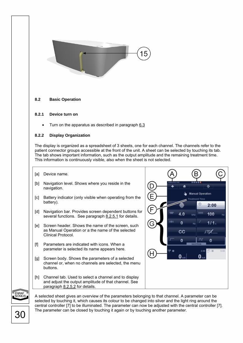
The display is organized as a spreadsheet of 3 sheets, one for each channel. The channels refer to the patient connector groups accessible at the front of the unit. A sheet can be selected by touching its tab. The tab shows important information, such as the output amplitude and the remaining treatment time. This information is continuously visible, also when the sheet is not selected. [a] Device name. [b] Navigation level. Shows where you reside in the
navigation. [c] Battery indicator (only visible when operating from the
battery). [d] Navigation bar. Provides screen dependent buttons for
several functions. See paragraph 8.2.5.1 for details. [e] Screen header. Shows the name of the screen, such
as Manual Operation or a the name of the selected Clinical Protocol.
[f] Parameters are indicated with icons. When a
parameter is selected its name appears here. [g] Screen body. Shows the parameters of a selected
channel or, when no channels are selected, the menu buttons.
[h] Channel tab. Used to select a channel and to display
and adjust the output amplitude of that channel. See paragraph 8.2.5.2 for details.
A selected sheet gives an overview of the parameters belonging to that channel. A parameter can be selected by touching it, which causes its colour to be changed into silver and the light ring around the central controller [7] to be illuminated. The parameter can now be adjusted with the central controller [7]. The parameter can be closed by touching it again or by touching another parameter.

31
To adjust the output amplitude of a channel, touch the tab of the selected channel again. Its colour will change into orange. The output amplitude can now be adjusted with the central controller [7]. For some applications, such as interferential therapy and combination therapy, two adjacent channels can be linked. Linked channels are indicated by a combined tab. The tab halves show the output amplitude of each channel, while the parameters on the remainder of the sheet apply to both channels. When you turn on the unit, you will first enter the Home menu. In the Home menu none of the channels are selected. The Home menu provides a structured access to all therapies available within the unit, with appropriate parameter defaults. Just select a menu item by touching the button to navigate to the next screen. You can navigate back to the previous screen by touching the back arrow at the top of the screen. Anywhere in the navigation, you can jump back to the Home menu, by touching the home button.
8.2.3 Navigation
8.2.3.1 Electrotherapy Home The Home menu gives access to all functions of the unit. Select the desired function or therapy by touching the button The next screen appears
Electrotherapy “Clinical Protocols” The electrotherapy menu gives access to functions
• Clinical Protocols • Favorites • Manual Operation • Programming
Select Clinical Protocols by touching the button The next screen appears
Use the central controller to scroll through the list and select the clinical protocol by touching the button. The channel selection screen appears. For therapy information touch the info button on the left side of the protocol and the therapy info will appear.

32
Therapy information Use the central controller to scroll through the pages, in most cases the first page is text followed by one or more illustrations. Touch the accept button in the navigation bar. The channel selection screen appears.
Channel Selection Here you can select the channels for electrotherapy. When channel 1 is selected, channel 2 is still available for another therapy When Channel 1+2 is selected both channels have the same parameters. Only the intensity can be set differently.
Parameter screen (therapy screen) In this screen the user can adjust the intensity or change the parameter by touching the button and changing the value with the central controller. If there is a vacuum unit available the user can set the vacuum settings direct from the menu.
Intensity setting To set the intensity, touch sheet 1 (Channel1) Read-out change to orange color and adjust with the central controller Timer starts count-down.

33
Electrotherapy “Manual Operation” The electrotherapy menu gives access to functions
• Clinical Protocols • Favorites • Manual Operation • Programming
Select Manual Operation by touching the button The next screen appears
Select from the list a current waveform Scroll to the next page with the central controller [7] or select the current waveform by touching the button Note: some of these selections are groups and in the next screen another list appears from which the current wave can be selected.
Channel Selection Here you can select the channels for electrotherapy. When channel 1 is selected, channel 2 is still available for another therapy When Channel 1+2 is selected both channels have the same parameters. Only the intensity can be set differently
Parameter screen Adjust the parameters by touching the button and change the value with the central controller [7] Note: some parameters are grouped and in the next screen the settings can be changed the same way as above
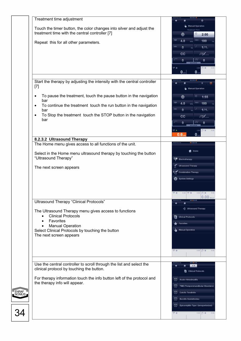
34
Treatment time adjustment Touch the timer button, the color changes into silver and adjust the treatment time with the central controller [7] Repeat this for all other parameters.
Start the therapy by adjusting the intensity with the central controller [7] • To pause the treatment, touch the pause button in the navigation
bar • To continue the treatment touch the run button in the navigation
bar • To Stop the treatment touch the STOP button in the navigation
bar
8.2.3.2 Ultrasound Therapy The Home menu gives access to all functions of the unit. Select in the Home menu ultrasound therapy by touching the button “Ultrasound Therapy” The next screen appears
Ultrasound Therapy “Clinical Protocols” The Ultrasound Therapy menu gives access to functions
• Clinical Protocols • Favorites • Manual Operation
Select Clinical Protocols by touching the button The next screen appears
Use the central controller to scroll through the list and select the clinical protocol by touching the button. For therapy information touch the info button left of the protocol and the therapy info will appear.

35
Therapy information Use the central controller [7] to scroll through the pages, in most cases the first page is text followed by one or more illustrations. Touch the accept button in the navigation bar. The parameter screen appears.
Touch the accept button in the navigation bar. The parameter screen appears.
The count-down starts when the contact control is de-activated Parameters can always be changed, before or during the treatment
8.2.3.3 Combination Therapy This therapy combines ultrasound and electrotherapy. The Home menu gives access to all functions of the unit. Select in the Home menu combination therapy by touching the button “Combination Therapy” The next screen appears

36
The Combination menu gives access to functions • Clinical Protocols • Favorites • Manual Operation Select Manual Operation by touching the button The next screen appears
Select in this menu the current waveform by touching the button
Adjust the current parameters and treatment time • Touch the parameter button and adjust with the central controller
[7]
• Select the ultrasound button to adjust the ultrasound parameters
• Touch the electrotherapy button to return to the previous screen
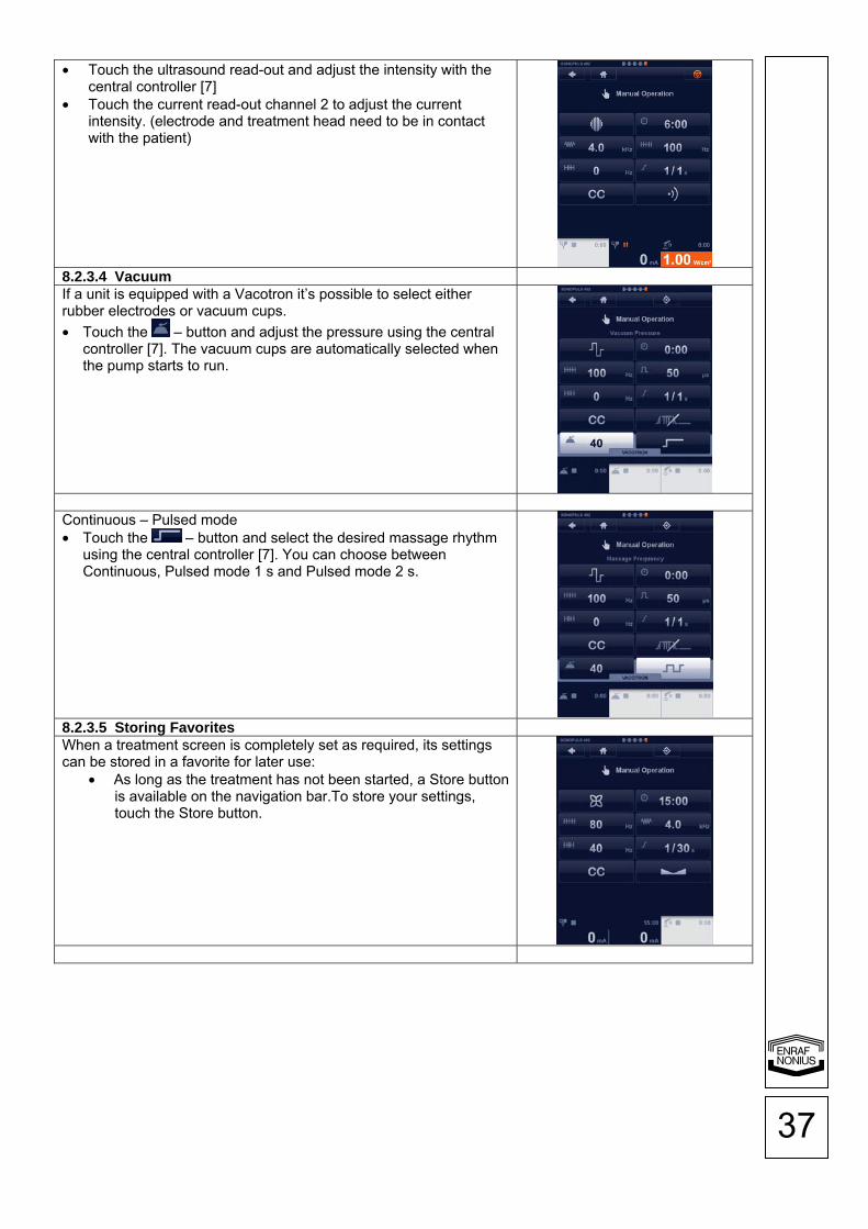
37
• Touch the ultrasound read-out and adjust the intensity with the central controller [7]
• Touch the current read-out channel 2 to adjust the current intensity. (electrode and treatment head need to be in contact with the patient)
8.2.3.4 Vacuum If a unit is equipped with a Vacotron it’s possible to select either rubber electrodes or vacuum cups.
• Touch the – button and adjust the pressure using the central controller [7]. The vacuum cups are automatically selected when the pump starts to run.
Continuous – Pulsed mode • Touch the – button and select the desired massage rhythm
using the central controller [7]. You can choose between Continuous, Pulsed mode 1 s and Pulsed mode 2 s.
8.2.3.5 Storing Favorites When a treatment screen is completely set as required, its settings can be stored in a favorite for later use:
• As long as the treatment has not been started, a Store button is available on the navigation bar.To store your settings, touch the Store button.

38
• Enter the name of your favorite using the keyboard. • Touch to store your favorite under the name just entered.
Notes:
• Once saved, favorites can be retrieved from the Electrotherapy, Ultrasound Therapy and Combination Therapy menus.
• 4-polar treatments are automatically saved and loaded as a dual channel treatment.
• Vacuum settings are not saved.
8.2.3.6 Programming a Sequential Protocol A sequential protocol consists of a series of treatment steps that are executed in a sequence until the end of the protocol is reached.
• Select Programming in the electrotherapy menu
• When a treatment screen is completely set as required, touch the
“next” button to add a next step. • Continue with the remaining treatment steps until you have
reached the end of your protocol. • Touch the Store button in the navigation bar. • Enter the name of your sequential protocol as described in
paragraph 8.2.3.5. Sequential protocols are stored under the Favorite menu.
8.2.3.7 System Settings The Home menu gives access to all functions of the unit. Select in the Home menu System Settings by touching the button “System Settings” The next screen appears

39
In this screen you can personalize the unit. Several settings can be changed or adjusted. • Language, touch the language button and select the desired
langue using the central controller [7]. Touch the language button again or touch another button to confirm.
• Brightness, here you can change the intensity of the backlight of the screen.
• Repeat this for all other options in the System Settings menu. • Touch the Back arrow in the navigation bar to return to the Home
menu.
8.2.4 Shutting device down
Turn off the device as described in paragraph 6.4.
8.2.5 Operating Details
8.2.5.1 Navigation Bar The following buttons can appear in the navigation bar [d].
Button Meaning
Back, return to previous screen.
Home, return to Home screen.
Page number / number of pages in multi page menu screens or treatment step number / number of treatment steps in sequential protocols.
Store therapy settings or a programmed sequential protocol in a favorite.
Delete Favorite.
Pause treatment. The output current decreases to 0 and the treatment timer suspends counting down.
Start/Continue treatment. The output current increases to the previous value and the treatment timer resumes counting down.
Accept the selected option.
Emergency Stop. Stop treatment on all channels simultaneously.
8.2.5.2 Channel Tab Information
Channel Tab Illustration [g] [h] [i] [j] [k]
[g] Output Indicator Standard electrodes
Vacuum electrodes
Ultrasound Applicator A

40
Ultrasound Applicator B
[h] Channel Status Channel stopped
Channel paused
Channel running
[i] Remaining treatment time. When a sequential protocol has been loaded, the value indicates the total remaining treatment time of the sequential protocol.
[j] Output value
[k] Unit of Output value: µA, mA, V, W, W/cm2
8.2.5.3 Adjusting current amplitude To adjust the output current, touch the tab of the selected channel. Its colour will change to orange, after which the current amplitude can be set with the central controller [7]. The current amplitude can only be adjusted when the clock has been set. With 4 polar interferential current waveforms the current amplitude operates on both channels simultaneously. In this case a balance facility is available for the classical interferential current waveform (see paragraph 4.1.3 for details). The unity of the displayed current amplitude depends on the previously selected current waveform and can be expressed in mA, µA or V. A treatment is started by adjusting the current amplitude, unless a surge program has been selected. To start a surge program, touch the Start/Continue button in the navigation bar (8.2.5.6). 8.2.5.4 CC/CV mode Depending on the selected current waveform, the electrotherapy channels can be used in the Constant Current or Constant Voltage mode. It is advised to use the CV mode with dynamic electrode applications. In CV mode the output current depends on the electrical contact with the patient and can therefore vary. You can change the CC/CV setting in the parameter menu. 8.2.5.5 Current polarity When DC currents are used, the red connection is the positive connection and the black one the negative connection. Manually changing the polarity during a treatment will result in a current decaying to 0, followed by a current with the opposite polarity, rising to a value equal to 80% of the previous value. 8.2.5.6 Surge Programs Surge programs allow you to program sequential increases and decreases in current amplitude. See fig 4.1.4.13 for details. Surge programs should not be confused with protocols:
• A single treatment step of a protocol could contain a surge program. With independent channel operation the surge programs run independently over both channels. They can independently be enabled and their parameters can individually be set. When the current channels are linked, the surge programs are also linked, which implies that their parameters have identical values. In this case a delay time can be set between the start of the surge on channel 1 and channel 2. A treatment with a Surge Program is started by first finding the desired current amplitude. During this time the system pauses. When the current amplitude has been established, the treatment can be started by touching the Start/Continue button in the navigation bar. Parameters:
41
Ramp-up time, expressed in s, defines the time in a surge program during which the current is increased from 0 to the adjusted level. See fig 4.1.4.13 for details. The ramp-up time can be adjusted in increments of 0.1s. Hold time, expressed in s, defines the time in a surge program during which the current is kept at the adjusted level. See fig 4.1.4.13 for details. The hold time can be adjusted in increments of 1s. Ramp-down time, expressed in s, defines the time in a surge program during which the current is decreased from the adjusted level to 0. See fig 4.1.4.13 for details. The ramp down time can be adjusted in increments of 0.1s. Interval time, expressed in s, defines the time in a surge program during which the current is kept at 0. See fig 4.1.4.13 for details. The interval time can be adjusted in increments of 1s. Delay time, expressed in s, defines the time delay between the start of the surge program on channel 1 and channel 2. See fig 4.1.4.13 for details. The delay time can be adjusted in increments of 0.1 s. Beep, if enabled, generates a short beep at the start of each surge.
9 Maintenance and Troubleshooting 9.1 Cleaning and Disinfection
9.1.1 Cleaning of apparatus
To clean the unit, turn it off and unplug the power supply. Clean the unit with a damp cloth. Do not use abrasive cleaners. A small amount of mild household detergent may be used, if needed.
9.1.2 Cleaning display panel
Use a soft and dry cotton cloth or micro fiber tissue to clean the panel. To remove fingerprints or grease, use a non-abrasive glass cleaning agent. Apply a small amount of the cleaning agent to a soft cotton cloth and then carefully clean the panel. CAUTION:
• Do not spray the cleaning agent directly on the glass panel. • Do not use cleaning agents that contain strong alkalis, lye, acid, detergents with fluoride or
detergents with ammonia.
9.1.3 Electrodes and accessories
Between patient uses, the rubber electrodes should be cleaned with lukewarm water. To disinfect the electrodes or to remove stubborn stains of dirt, use a 70% alcohol solution. The alcohol solution can cause the black color to be stained, but this does not affect the operation of the electrodes. Between patient uses, the sponge pads should be washed in warm water, using a household cleaning agent. After washing they must be rinsed with clear water, thoroughly drained and then dried. Damaged sponge pads should be replaced.
9.1.4 Patient cable
Clean the patient cable with a damp cloth. Use lukewarm water and a non-abrasive household cleaning agent. Do not use an alcohol solution. Check the cable regularly for damages and/or bad electrical contact. We advise, keeping a spare patient cable in stock.
9.1.5 Ultrasound applicator
To prevent corrosion, clean and dry the contact surface immediately after use. Make sure that no ultrasound gel remains on the applicator. We further recommend cleaning the applicator and cable daily, using lukewarm water. The applicator can be disinfected using a cloth moistened with a 70% alcohol solution. Check the applicator and cable regularly for damage.
42
9.1.6 Vacuum electrodes and sponges
The vacuum electrodes and sponges should be cleaned with lukewarm water. In the case of persistent dirt, and for disinfection, a 70% alcohol solution may be used. Sponges should be replaced regularly. It is recommended to keep sponges and a spare electrode in stock. Calcium scale can be deposited on the metal surfaces of the electrodes. This has an insulating effect. In order to maintain optimum conductivity, these surfaces should be regularly cleaned and polished.
9.1.7 Vacuum cables
Clean the vacuum cable with a damp cloth. Use lukewarm water and a non-abrasive household cleaning agent. Do not use an alcohol solution. Check the cable regularly for damages and/or bad electrical contact. We advise, keeping a spare vacuum cable in stock.
9.1.8 Cleaning the water reservoir and hoses:
• Detach the vacuum cups from the vacuum cables. • Place a container filled with a cleaning liquid (1) below the system. • Place the peripheral ends of the cables in the container. • Go to System Settings and select Tank Cleaning. • The water reservoir will be filled with the cleaning liquid until the water reservoir is full. • Empty the water reservoir as described in 9.2.4.
(1) The following registered products may be used for disinfecting the water reservoir: BAKTOLAN to 5%, CHINOSOL to 1%, CHLORAMIN solution, ELMOCID Gamma to 2%, MEFAROL to
1%, MERCKOJOD to 1%, MERFEN, PERHYDROL, PERODIN, SAGROTAN to 2%, ZEPHIROL to 5%.
9.2 Warning Messages, Error Messages and Troubleshooting
9.2.1 Error code
When the apparatus is turned on, it will first execute a self test. When an error is detected, both during the self test and during normal operation, a pop-up screen will appear on the display. When the error is displayed, all outputs will be disabled. When this situation occurs, remove all cables and switch the apparatus off and switch it on again. When the error re-appears, stop using the device and contact your supplier.
9.2.2 Patient Circuit Interrupted
There is insufficient or no output current available at the outputs. Possible causes: • Poor electrical contact or broken patient cable. • Insufficiently moistened sponges. If necessary, use a saline solution to improve the electrical
conductivity of the water. • Too high current amplitude with self adhesive electrodes. Try to continue the treatment with
flexible rubber electrodes. If the problem occurs in CC mode, the current amplitude will ramp down to 0 and will have to be readjusted when the problem has been solved. If none of the above scenarios appear to be the problem, stop using the device and contact your supplier.
9.2.3 Battery Low
The battery is insufficiently charged to complete the treatment at the currently set therapy levels. Reduce the therapy levels or connect the apparatus to the mains supply.

43
9.2.4 Water Reservoir Full
The water separation tank of the Vacotron is full. Continue the treatment with the standard electrodes or empty the tank as follows:
• Set power line switch [1] Off (0). • Detach the hose from the upper hose nipple [15] and empty the reservoir. • Reattach the hose to the hose nipple. • Set power line switch [1] On (1).
9.2.5 Vacuum Leak
There probably is a leak in the vacuum system. This error is usually preceded by a continuously running pump trying to reach the set vacuum. To protect the system, the pump is automatically stopped after a certain amount of time. Inspect the vacuum cables and electrodes, set the vacuum back to zero and try again. If the failure persists, stop using the device and contact your supplier.
9.2.6 Ultrasound Applicator Error
The ultrasound applicator has reported an error. Disconnect the device, wait some time and reconnect it. If the error persists, stop using the device and contact your supplier.
9.2.7 Insufficient DC Supply
This problem can sometimes occur with the small ultrasound applicator when operating from the battery. If possible, continue the treatment with reduced therapy levels or connect the apparatus to the mains supply. 9.3 User Maintenance
9.3.1 Optimize Contact Control Ultrasound Applicator
When you experience difficulties with the contact control function of the ultrasound applicator you can try to resolve the problem as follows:
• Ensure that the surface of the ultrasound applicator is clean and dry. • Place the ultrasound applicator in the holder. • Go to System Settings -> Maintenance and select Optimize Applicator A or B. • Touch the OK-button when the operation is complete.
9.3.2 Back-up and Restore Favorites
When you have programmed and stored several Favorites, you might want to make a back-up on an external storage device. To store your favorites, proceed as follows:
• Attach a USB-stick to the remote control connection [3]. Read and obey the warnings and cautions mentioned in paragraph 8.1.
• Go to Systems Settings -> Maintenance and select Back-up Favorites. • If an error occurs during the back-up operation, i.e. USB-stick full, this will be displayed in a pop-
up message. • Touch the OK-button when the operation is complete. • Detach the USB-stick
To restore your favorites:
• Attach the USB-stick containing your Favorites to the remote control connection [3]. Read and obey the warnings and cautions mentioned in paragraph 8.1.
• Go to Systems Settings -> Maintenance and select Restore Favorites. • If an error occurs during the restore operation, i.e. no favorites found, this will be displayed in a
pop-up message. • Touch the OK-button when the operation is complete.

44
• Detach the USB-stick
9.3.3 Firmware Update
If your system requires a Firmware Update, contact your supplier to obtain a USB-stick containing the latest firmware version. Your current firmware version can be viewed under System Settings. To update your firmware proceed as follows:
• Attach the USB-stick containing the firmware to the remote control connection [3]. Read and obey the warnings and cautions mentioned in paragraph 8.1.
• Go to Systems Settings -> Maintenance and select Update Firmware. • If an error occurs during the update operation, i.e. no firmware found, this will be displayed in a
pop-up message. • Touch the OK-button when the operation is complete. • Detach the USB-stick
9.4 Technical Maintenance On request a service manual can be made available containing: spare part list, descriptions, calibration instructions and other information which will assist the user’s qualified technical personnel to repair those parts of the equipment which are designated by the manufacturer as repairable. CAUTION:
• Electrical safety of the device relies on a properly earthed electrical connection via the power cord. It is therefore necessary to have this connection checked annually.
• To ensure continued compliance with the 21 CFR 1050.10 standard, this unit should be adjusted and safety tested once each year. Procedures laid down in the service manual should be followed. This may be carried out by your supplier, or by another agency, authorized by the manufacturer. It is also recommended that a service history record is maintained. In some countries this is even obligatory.
• Use of controls or adjustments or performance of procedures other than those specified herein may result in hazardous exposure to ultrasonic energy.
WARNING:
• This unit operates with high voltages. No attempt should be made to disassemble the unit. Maintenance and repair should be carried out by authorized personnel only. The manufacturer will not be held responsible for the results of maintenance or repairs by unauthorized persons.
All other technical maintenance is restricted to authorized Enraf-Nonius maintenance personnel. Authorized service personnel can make use of 1498770 Service manual 4-series 9.5 End of life
The 4-series contains materials that can be recycled and/or are noxious to the environment. Specialized companies can dismantle the unit and sort out these materials. When you dispose of the unit, find out about local regulations concerning waste management.

45
10 Specifications 10.1 Ultrasound parameters Continuous ultrasound
Explanation of symbols:
f Ultrasonic radiation with an
acoustic working frequency of 1 or 3 MHz
fp Pulse repetition rate
dc Duty cycle
t Pulse duration
Pulsed ultrasound
Ultrasound parameters: f Acoustic working frequency: 1MHz or 3MHz fp Pulse repetition rate: 16, 48 and 100 Hz dc Duty cycle: 5 – 80 % t Pulse duration: 0.5 – 8 ms, set by duty cycle RTPA 20 – 1.25
Amplitude modulation
Duty cycle Pulse duration
RTPA Amplitude modulation
Duty cycle Pulse duration
RTPA
16Hz 5% 3.1ms 20 48Hz 50% 10.4ms 2
16Hz 10% 6.3ms 10 48Hz 80% 16.7ms 1.25
16Hz 20% 12.5ms 5 48Hz 100%* 20.8ms 1
16Hz 33% 20.6ms 3 100Hz 5% 0.5ms 20
16Hz 50% 31.3ms 2 100Hz 10% 1ms 10
16Hz 80% 50ms 1.25 100Hz 20% 2ms 5
16Hz 100%* 62.5ms 1 100Hz 33% 3.3ms 3.33
48Hz 5% 1ms 20 100Hz 50% 5ms 2
48Hz 10% 2.1ms 10 100Hz 80% 8ms 1.25
48Hz 20% 4.2ms 5 100Hz 100%* 10ms 1
48Hz 33% 6.9ms 3.33 * = continuous mode Generator Peak output Amplitude: Duty cycle 5 – 50 % : 0 – 3 W/cm² Duty cycle 80 % : 0 – 2.5 W/cm² Duty cycle 100 % : 0 – 2 W/cm² (continuous wave) Peak output power for 5 cm² applicator: Duty cycle 5 – 50 % : 0 – 15 W Duty cycle 80 % : 0 – 12 W Duty cycle 100 % : 0 – 10 W (continuous wave) Peak output power for 0.8 cm² applicator: Duty cycle 5 – 50 % : 0 – 2.4 W Duty cycle 80 % : 0 – 2 W Duty cycle 100 % : 0 – 1.6 W (continuous wave)

46
Output meter uncertainty : ± 20 % for any output above 10 % of maximum Pulse frequency : 16, 48 and 100 Hz ± 1 % Duty cycle : 5 – 80 % and 100 % (100 % is continuous wave) Pulse duration : 0.5 – 8 ms ± 10 % (set by duty cycle) Temporal Peak to Average Ratio (RTPA) :20 – 1.25 ± 10 % (set by duty cycle) Treatment timer : 0 - 30 min ± 0.1 min, linked to contact control Contact control level : 65% 5 cm² Applicator Ultrasound frequency: 1 MHz : 0.98 MHz ± 2 % 3 MHz : 3.1 MHz ± 2 % ERA (Effective Radiation Area): IEC 60601-2-5: 2000 : 4 cm2 21 CFR 1050.10 : 5 cm2 Beam type: 1 MHz : Collimating 3 MHz : Collimating BNR (Beam Non-uniformity Ratio) : 6:1 maximum Side radiation : 10 mW/cm² maximum 0.8 cm² Applicator Ultrasound frequency: 1 MHz : 0.98 MHz ± 2 % 3 MHz : 3.1 MHz ± 2 % ERA (Effective Radiation Area): IEC 60601-2-5: 2000 : 4 cm2 21 CFR 1050.10 : 5 cm2 Beam type: 1 MHz : Collimating 3 MHz : Diverging BNR (Beam Non-uniformity Ratio) : 6:1 maximum Side radiation : 10 mW/cm² maximum Description of ultrasound area The spatial distribution of the radiated field is a collimated beam (diverging for the 0.8 cm² applicator at 3 MHz) of ultrasound energy, with a decreasing Amplitude at increasing distance from the applicator surface. This field distribution applies to the radiation emitted into the equivalent of an infinite medium of distilled, degassed water at 30 ºC and with line voltage variations in the range of ± 10% of the rated value. The ultrasonic beam is characterized by the Effective Radiation Area (ERA) and the Beam Non-uniformity Ratio (BNR). The Effective Radiation Area is the cross-sectional area of the ultrasound beam. Its value can be set under System Settings (8.2.3.7) and depends on the ultrasound standard used:
• International: IEC 60601-2-5: 2000 • USA: 21 CFR 1050.10
The Beam Non-uniformity Ratio is the ratio of the maximum ultrasound Amplitude to the average ultrasound Amplitude, measured at the Effective Radiation Area. A low BNR value is indicative for the absence of high and potentially dangerous energy concentrations. 10.2 Stimulator output parameters Electrotherapy general Channels : 2 Output characteristics : Constant Current (CC) or Constant Voltage (CV), except for
High Voltage (CV) and Microcurrent (CC). Current amplitude range : Depending on current waveform Current amplitude resolution : 0.2 mA Treatment timer : 0 - 60 minutes Polarity reversion direct currents : manual

47
The maximum current amplitude within the specification is achieved up to a load of 500 Ω (CC). Surge program With some current waveforms a surge program is available. The parameters and their range are as follows: Ramp-up time : 0 - 9 s, in steps of 1s Hold time : 0 - 60 s, in steps of 1 second Ramp-down time : 0 - 9 s, in steps of 1s Interval time : 0 - 120 s, in steps of 1 second Delay time : 0.1 - 80 s, below 10s in steps of 0.1s, otherwise in steps of 1s Interferential, 4 polar Carrier Frequency : 2, 2.5, 3, 3.5, 4, 5, 6, 7, 8, 9, 10 kHz Beat Frequency (AMF) : 0 – 200 Hz in steps of 1 Hz Frequency Modulation (spectrum) : 0 - 180 Hz in steps of 1 Hz Modulation program : 1/1, 6/6, 12/12, 1/30/1/30 s Amplitude : 0 - 100 mA Isoplanar vector Carrier Frequency : 2, 2.5, 3, 3.5, 4, 5, 6, 7, 8, 9, 10 kHz Beat Frequency (AMF) : 0 – 200 Hz in steps of 1 Hz Frequency Modulation (spectrum) : 0 – 180 Hz in steps of 1 Hz Modulation program : 1/1, 6/6, 12/12, 1/30/1/30 s Amplitude : 0 - 100 mA Dipole Vector Automatic Carrier Frequency : 2, 2.5, 3, 3.5, 4, 5, 6, 7, 8, 9, 10 kHz Beat Frequency (AMF) : 0 – 200 Hz in steps of 1 Hz Amplitude : 0 - 100 mA Rotation time : 1 - 10 s in steps of 1 s Dipole Vector Manual Carrier Frequency : 2, 2.5, 3, 3.5, 4, 5, 6, 7, 8, 9, 10 kHz Beat Frequency (AMF) : 0 – 200 Hz in steps of 1 Hz Frequency Modulation (spectrum) : 0 – 180 Hz in steps of 1 Hz Modulation Program : 1/1, 6/6, 12/12, 1/30/1/30 s Amplitude : 0 - 100 mA Resolution vector : 2.25° per step (160 steps over 360°) Asymmetrical Phase Duration : 10 - 400 µs in steps of 5 µs Pulse Frequency : 1 - 200 Hz, in steps of 1 Hz Frequency Modulation : 0 – 180 Hz, in steps of 1 Hz Modulation Program : 1/1, 6/6, 12/12, 1/30/1/30 s Surge Program : Yes Amplitude : 0 - 140 mA Asymmetrical Alternating Phase Duration : 10 - 400 µs in steps of 5 µs Pulse Frequency : 1 - 200 Hz, in steps of 1 Hz Frequency Modulation : 0 – 180 Hz, in steps of 1 Hz Modulation Program : 1/1, 6/6, 12/12, 1/30/1/30 s Surge Program : Yes Amplitude : 0 - 140 mA Burst Asymmetrical Phase Duration : 10 - 400 µs in steps of 5 µs Pulse Frequency : 1 - 200 Hz, in steps of 1 Hz Burst Frequency : 1 – 9 Hz, in steps of 1 Hz Amplitude : 0 - 140 mA Burst Asymmetrical Alternating Phase Duration : 10 - 400 µs in steps of 5 µs Pulse Frequency : 1 - 200 Hz, in steps of 1 Hz

48
Burst Frequency : 1 – 9 Hz, in steps of 1 Hz Amplitude : 0 - 140 mA Symmetrical Phase Duration : 10 - 400 µs in steps of 5 µs Pulse Frequency : 1 - 200 Hz, in steps of 1 Hz Frequency Modulation (spectrum) : 0 - 180 Hz in steps of 1 Hz Modulation Program : 1/1, 6/6, 12/12, 1/30/1/30 s Surge Program : Yes Amplitude : 0 - 140 mA Burst Symmetrical Phase Duration : 10 - 400 µs in steps of 5 µs Pulse Frequency : 1 - 200 Hz, in steps of 1 Hz Burst Frequency : 1 – 9 Hz, in steps of 1 Hz Amplitude : 0 - 140 mA Premodulated Carrier Frequency : 2, 2.5, 3, 3.5, 4, 5, 6, 7, 8, 9, 10 kHz Beat Frequency : 0 - 200 Hz in steps of 1 Hz Frequency Modulation (spectrum) : 0 - 180 Hz in steps of 1 Hz Modulation program : 1/1, 6/6, 12/12, 1/30/1/30 s Surge Program : Yes Amplitude : 0 - 140 mA Russian Stimulation Carrier Frequency : 2, 2.5, 3, 3.5, 4, 5, 6, 7, 8, 9, 10 kHz Burst frequency : 0 - 100 Hz in steps of 1 Hz Burst / Pause : 1:1, 1:2, 1:3, 1:4, 1:5 Surge Program : Yes Amplitude : 0 - 100 mA High Voltage (Twin Pulse) Frequency : 1- 200 Hz in steps of 1 Hz Frequency Modulation (spectrum) : 0 – 180 Hz in steps of 1 Hz, sum of Pulse frequency and
Frequency Modulation can not exceed 200 Hz Modulation Program : 1/1, 6/6, 12/12, 1/30/1/30 s Surge Program : Yes Polarity : Positive or Negative Amplitude : 0 – 500 Volt in steps of 1V High Voltage Alternating (Twin Pulse) Frequency : 1 – 200 Hz in steps of 1 Hz Frequency Modulation (spectrum) : 0 – 180 Hz in steps of 1 Hz, sum of Pulse frequency and
Frequency Modulation can not exceed 200 Hz Modulation program : 1/1, 6/6, 12/12, 1/30/1/30 s Alternating Period : 10 -100 seconds in steps of 10 Ramp-in, ramp out : 0,5 seconds Amplitude : 0 – 500 Volt in steps of 1 Volt Micro Current Frequency : 0 – 1000 Hz Polarity : Positive or Negative Surge Program : Yes Amplitude : 10 µA - 1 mA in steps of 10 µA Micro Current Alternating Frequency : 0 – 1000 Hz Alternating Period : 0,2 – 20 seconds, 0,2 – 1 s in steps of 0,1s, 1 – 20 s in steps of 1
s. Ramp-in, ramp out : 0 seconds Amplitude : 10 µA - 1 mA in steps of 10 µA Diadynamic current Settings : MF, DF, CP, LP en CPid

49
Surge Program : on MF and DF Polarity : Positive or Negative Amplitude : 0 - 70 mA MF interrupted galvanic current Frequency : 8000 Hz Duty cycle : 90% Polarity : Positive or Negative Amplitude : 0 - 40 mA Direct Galvanic current Polarity : Positive or Negative Amplitude : 0 – 40 mA Faradic Rectangular Pulsed Current Phase Duration : 0.02 – 1000 ms Pulse Frequency : 0.2 – 1 Hz in steps of 0.1 Hz, 1 – 200 in steps of 1 Hz Surge Program : Yes Polarity : Positive or Negative Amplitude : 0 - 80 mA Faradic Triangular Pulsed Current Phase duration : 0.1 – 1000 ms Pulse Frequency : 0.2 – 1 Hz in steps of 0.1 Hz, 1 – 200 in steps of 1 Hz Surge program : Yes Polarity : Positive or Negative Amplitude : 0 - 80 mA Träbert 2-5 (Rectangular Pulsed Current) Phase duration : 2 ms Interval : 5 ms Polarity : Positive or Negative Amplitude : 0 - 80 mA 10.3 Technical Data Mains voltage : 100 – 240 V ± 10% Mains frequency : 50 / 60 Hz Main unit: Dimensions stand alone : 24 x 32 x 12 cm (w x d x h) Dimensions on inclination foot : 24 x 30.5 x 18.2 cm (w x d x h) Dimensions on Vacotron : 24 x 30.5 x 21.6 cm (w x d x h) Weight : 2 Kg Weight including optional battery : 3 Kg Vacotron: Dimensions : 24 x 28.6 x 9.3 cm (w x d x h) Weight : 2 Kg Environmental conditions for transport and storage: Temperature : -20° to +70° C Relative humidity : 10 to 90 % (contained in original packaging) Atmospheric pressure : 500 to 1060 hPa Environmental conditions for normal use: Temperature : 10° to 40° C Relative humidity : 10 to 90 % non condensing Atmospheric pressure : 500 to 1060 hPa Technical modifications reserved

50
10.4 Safety and Performance standards IEC 60601-1 : General requirements for the safety of electrical medical
systems, including Annex 1, national differences for Australia, Canada and the United States.
Safety class according to IEC 60601-1: class I type BF IEC 60601-2-5 : Particular requirements for the safety of ultrasonic therapy
equipment. IEC 60601-2-10 : Particular requirements for the safety of nerve and muscle
stimulators.
: This equipment complies with all requirements of the Medical Device Directive (93/42/EEC).
Medical device classification : IIa 21 CFR 1050.10 : This equipment complies with all requirements of 21 CFR
1050.10, Performance Standard for Ultrasonic Therapy devices.
21 CFR 898 : This equipment complies with all requirements of 21 CFR 898,
Performance Standard for electrode lead wires and patient leads.
10.5 EMC details Medical electrical devices such as the 4-series are subject to special precautions with regard to electromagnetic compatibility (EMC) and must be installed and commissioned in accordance with the EMC advice given in the instructions for use and accompanying documents. Portable and mobile RF communication systems (e.g. mobile phones) may interfere with medical electrical 4-series. The 4-series should only be operated with the original mains cable specified in the list of contents delivered. Operating the device with any other mains cable can lead to increased emissions or reduced interference immunity of the device.
Guidelines and manufacturer's declaration – electromagnetic interference
The 4-series device is intended for operation in an electromagnetic environment as indicated below. The customer or user of the 4-series unit should ensure that it is operated in such an environment.
Interference tests Conformity Electromagnetic environment guideline
RF emissions according to CISPR 11 Group 1 The 4-series device uses RF energy solely for its internal functioning. Its RF emission is therefore very low and it is unlikely that this will cause interference to neighbouring electronic 4-series.
RF emissions according to CISPR 11 ClassB The 4-series device is suitable for use in all installations including those in a residential environment and those which are directly connected to the public mains network which also supplies buildings which are used for residential purposes.
Harmonic emissions according to IEC 61000-3-2
Class B
Voltage fluctuation emissions and flicker according to IEC 61000-3-3
Conforms

51
The device should not be used when placed immediately next to or stacked on top of other devices. If operation is necessary when immediately next to or stacked on top of other devices, the device should be monitored to ensure it is operating as intended in this arrangement.
Guidance and manufacturer’s declaration – Electromagnetic immunity
The 4-series device is intended for use in the electromagnetic environment specified below. The customer or the user of the 4-series device should assure that it is used in such an environment.
Immunity test IEC 60601 test level
Compliance level Electromagnetic environment - Guidance
Electrostatic discharge (ESD) to IEC 61000-4-2
± 6 kV contact ± 8 kV air
± 6 kV contact ± 8 kV air
Floors should be wood, concrete or ceramic tile. If floors are covered with synthetic material, the relative humidity should be at least 30%.
Electrical fast transient / burst to IEC 61000-4-4
± 2 kV for power supply lines ± 1 kV for input / output lines
± 2 kV for power supply lines not applicable
Mains power quality should be that of a typical commercial or hospital environment.
Surge IEC 6100-4-5 ± 1 kV differential mode ± 2 kV common mode
± 1 kV differential mode ± 2 kV common mode
Mains power quality should be that of a typical commercial or hospital environment.
Voltage dips, short interruptions and voltage variations on power supply input lines IEC 61000-4-11
<5% UT (>95% dip in UT for 0.5 cycle) 40% UT (60% dip in UT for 5 cycles) 70% UT (30% dip in UT for 25 cycles) <5% UT (>95% dip in UT for 5 seconds)
<5% UT (>95% dip in UT for 0.5 cycle) 40% UT (60% dip in UT for 5 cycles) 70% UT (30% dip in UT for 25 cycles) <5% UT (>95% dip in UT for 5 seconds)
Mains power quality should be that of a typical commercial or hospital environment. If the use of the 4-series device requires continued operation during mains power interruptions, it is recommended to install a battery.
Power frequency (50/60 Hz) magnetic field to IEC 61000-4-8
3 A/m 3 A/m Power frequency magnetic fields should be at levels characteristic of a typical location in a typical commerical or hospital environment.
Note: UT is the AC mains voltage prior to application of the test level.

52
The main features of the 4-series devices are as follows: interference-free delivery of shockwaves, interference-free control of all functions. Uninterrupted operation is not required with the use intended.
Guidelines and manufacturer's declaration – electromagnetic interference immunity
The 4-series device is intended for operation in the electromagnetic environment specified below. The customer or user of the 4-series should ensure that it is used in such an environment.
Interference immunity tests
IEC 60601-test level
Compliance level Electromagnetic environment - guidelines
Conducted RF disturbance variables according to IEC 61000-4-6 Radiated RF disturbance variables according to IEC 61000-4-3
3 Veffective value 150 kHz to 80 MHz 3 V/m 80 MHz to 2.5 GHz
3 Veffective value 150 kHz to 80 MHz 3 V/m 80 MHz to 2.5 GHz
Portable and mobile radio should not be used any closer to the 4-series devices, including cables, than the recommended separation distance calculated from the equation applicable to the transmission frequency. Recommended separation distance: d= 1.2 √P d= 0.35 √P for 80 MHz to 800 MHz d= 0,7 √P for 800 MHz to 2.5 GHz Where P is the rated power of the transmitter in Watts (W) according to the transmitter manufacturer and d is the recommended separation distance in meters (m). According to an investigation in situa, the field strength of stationary radio transmitters should be less than the compliance level at all frequencies. Interference may occur in the vicinity of 4-series devices which is marked with the following symbol:
NOTE 1 At 80 MHz and 800 MHz the higher frequency range is applicable. NOTE 2 These guidelines may not be applicable in all cases. Electromagnetic propagation is affected by absorption and reflection from structures, objects and people.
a Theoretically, it is not possible to exactly predict the field strengths of fixed transmitters such as base stations for radio telephones and land mobile radios, amateur radio stations, AM and FM radio and TV broadcasting. To determine the electromagnetic environment in relation to the fixed transmitters, an electromagnetic site survey should be considered. If the measured field strength in the location where the 4-series device is to be used exceeds the above compliance levels, the 4-series device should be monitored in order to ensure that it is functioning as intended. If unusual features are noticed, additional measures may be necessary such as re-orienting or relocating the 4-series device. b Above the frequency range from 150 kHz to 80 MHz the field strength should be less than 3 V/m.
Recommended separation distances between portable and mobile RF telecommunications 4-series and the 4-series device
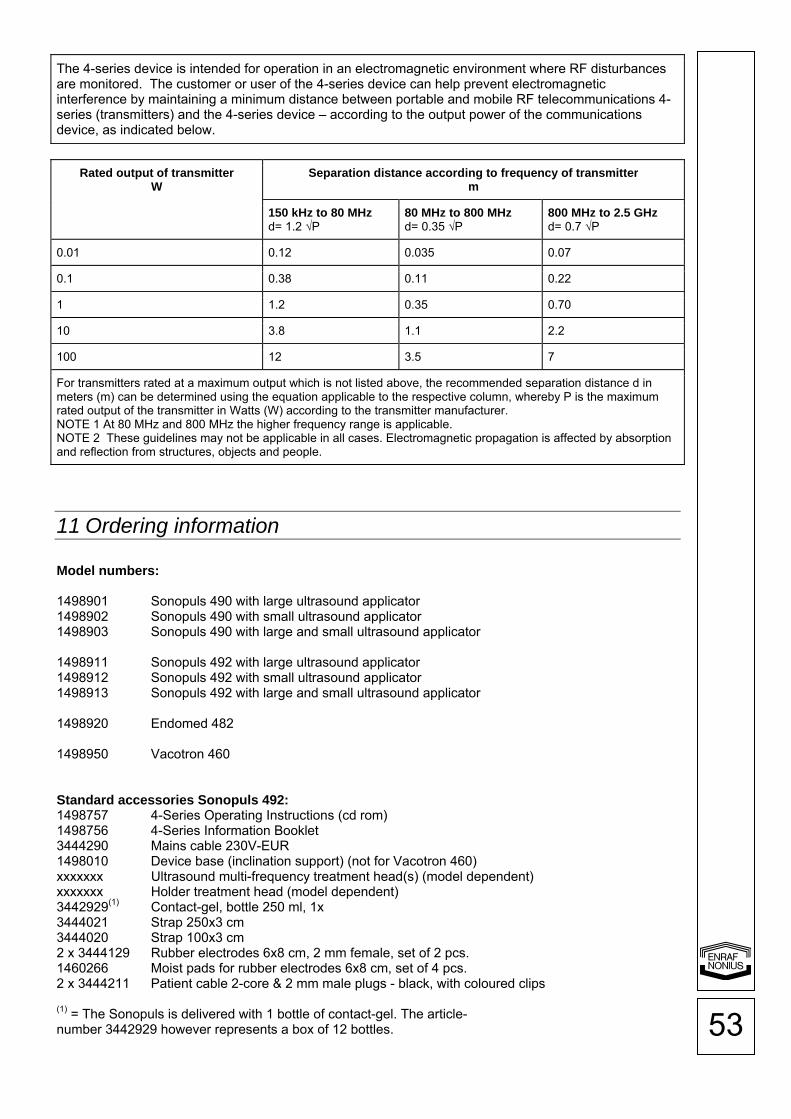
53
The 4-series device is intended for operation in an electromagnetic environment where RF disturbances are monitored. The customer or user of the 4-series device can help prevent electromagnetic interference by maintaining a minimum distance between portable and mobile RF telecommunications 4-series (transmitters) and the 4-series device – according to the output power of the communications device, as indicated below.
Rated output of transmitterW
Separation distance according to frequency of transmitter m
150 kHz to 80 MHzd= 1.2 √P
80 MHz to 800 MHzd= 0.35 √P
800 MHz to 2.5 GHzd= 0.7 √P
0.01 0.12 0.035 0.07
0.1 0.38 0.11 0.22
1 1.2 0.35 0.70
10 3.8 1.1 2.2
100 12 3.5 7
For transmitters rated at a maximum output which is not listed above, the recommended separation distance d in meters (m) can be determined using the equation applicable to the respective column, whereby P is the maximum rated output of the transmitter in Watts (W) according to the transmitter manufacturer. NOTE 1 At 80 MHz and 800 MHz the higher frequency range is applicable. NOTE 2 These guidelines may not be applicable in all cases. Electromagnetic propagation is affected by absorption and reflection from structures, objects and people.
11 Ordering information Model numbers: 1498901 Sonopuls 490 with large ultrasound applicator 1498902 Sonopuls 490 with small ultrasound applicator 1498903 Sonopuls 490 with large and small ultrasound applicator 1498911 Sonopuls 492 with large ultrasound applicator 1498912 Sonopuls 492 with small ultrasound applicator 1498913 Sonopuls 492 with large and small ultrasound applicator 1498920 Endomed 482 1498950 Vacotron 460 Standard accessories Sonopuls 492: 1498757 4-Series Operating Instructions (cd rom) 1498756 4-Series Information Booklet 3444290 Mains cable 230V-EUR 1498010 Device base (inclination support) (not for Vacotron 460) xxxxxxx Ultrasound multi-frequency treatment head(s) (model dependent) xxxxxxx Holder treatment head (model dependent) 3442929(1) Contact-gel, bottle 250 ml, 1x 3444021 Strap 250x3 cm 3444020 Strap 100x3 cm 2 x 3444129 Rubber electrodes 6x8 cm, 2 mm female, set of 2 pcs. 1460266 Moist pads for rubber electrodes 6x8 cm, set of 4 pcs. 2 x 3444211 Patient cable 2-core & 2 mm male plugs - black, with coloured clips (1) = The Sonopuls is delivered with 1 bottle of contact-gel. The article- number 3442929 however represents a box of 12 bottles.

54
Standard accessories Sonopuls 490: 1498757 4-Series Operating Instructions (cd rom) 1498756 4-Series Information Booklet 3444290 Mains cable 230V-EUR 1498010 Device base (inclination support) (not for Vacotron 460) xxxxxxx Ultrasound multi-frequency treatment head(s) (model dependent) xxxxxxx Holder treatment head (model dependent) 3442929(1) Contact-gel, bottle 250 ml, 1x (1) = The Sonopuls is delivered with 1 bottle of contact-gel. The article- number 3442929 however represents a box of 12 bottles. Standard accessories Endomed 482: 1498757 4-Series Operating Instructions (cd rom) 1498756 4-Series Information Booklet 3444290 Mains cable 230V-EUR 1498010 Device base (inclination support) (not for Vacotron 460) 3444021 Strap 250x3 cm 3444020 Strap 100x3 cm 2 x 3444129 Rubber electrodes 6x8 cm, 2 mm female, set of 2 pcs. 1460266 Moist pads for rubber electrodes 6x8 cm, set of 4 pcs. 2 x 3444211 Patient cable 2-core & 2 mm male plugs - black, with colour clips Standard accessories Vacotron 460: 1498756 4-Series Information Booklet 2 x 3444503 Vacuum electrodes Ø 60 mm, set of 2 pcs. 3444505 Sponges Ø 65 mm, set of 4 (for vacuum electrodes Ø 60 mm) 2 x 3444507 Vacuum lead hose red 2 x 3444508 Vacuum lead hose black Optional accessories: Ultrasound contact-gel 3442929 Contact-gel, bottle 250 ml, box of 12 3442930 Contact-gel, bottle 850 ml, box of 12 3442931 Contact-gel, canister of 5 l 3442932 Dispenser-set for 5 l canister electrodes and moist pads Adhesive electrodes 3444222 Adhesive electrodes Ø 2,2 cm, 2 mm female, 10 sheets of 8 (also for EMG) 3444056 EN-Trode Ø 3,2 cm, 2 mm female,10 sheets of 4 3444135 EN-Trode Ø 5,0 cm, 2 mm female, 10 sheets of 4 3444057 EN-Trode 5x5 cm, 2 mm female, 10 sheets of 4 3444058 EN-Trode 5x9 cm, 2 mm female, 10 sheets of 4 Rubber electrodes 3444128 Rubber electrodes 4x6 cm, 2 mm female, set of 2. 3444129 Rubber electrodes 6x8 cm, 2 mm female, set of 2 3444130 Rubber electrodes 8x12 cm, 2 mm female, set of 2 Moist pads for rubber electrodes 1460273 Moist pads for rubber electrodes 4x6 cm, set of 4 1460266 Moist pads for rubber electrodes 6x8 cm, set of 4 1460275 Moist pads for rubber electrodes 8x12 cm, set of 4 Fixation straps 3444020 Strap 100x3 cm 3444021 Strap 250x3 cm 3444022 Strap 100x5 cm 3444023 Strap 250x5 cm

55
Point electrodes 1480800 Electrode holder for 1480801 1480801 Point electrode 5 mm, 4 mm female (in combination with adapters 2523523 / 2523524) 1460369 Point electrode, 17 mm, 4 mm female (in combination with adapters 2523523 / 2523524) Adapters 2523524 Adapter plug, 2 mm female, 4 mm male, red 2523523 Adapter plug, 2 mm female, 4 mm male, black Patient cable 3444211 Patient cable 2-core & 2 mm male plug - black, with coloured clips Bag 3444675 Carrierbag 4-series Battery 2501016 Battery 12.0V 1.8AH Vacuum accessories Vacotron 460 3444509 Vacuum electrodes Ø 30 mm, set of 2 3444503 Vacuum electrodes Ø 60 mm, set of 2 3444504 Vacuum electrodes Ø 90 mm, set of 2 3444516 Sponges Ø 30 mm, set of 4 (for vacuum electrodes Ø 30 mm) 3444505 Sponges Ø 65 mm, set of 4 (for vacuum electrodes Ø 60 mm) 3444506 Sponges Ø 95 mm, set of 4 (for vacuum electrodes Ø 90 mm) 3444507 Vacuum lead hose, red 3444508 Vacuum lead hose, black www.enraf-nonius.com