uic00a usb icsp pic programmer...uic00a usb icsp pic programmer user’s manual v1.8 oct 2009 or use...
TRANSCRIPT
UIC00A USB ICSP PIC PROGRAMMER
User’s Manual
V1.8
Oct 2009
Information contained in this publication regarding device applications and the like is intended through suggestion only and may be superseded by updates. It is your responsibility to ensure that your application meets with your specifications. No representation or warranty is given and no liability is assumed by Cytron Technologies Incorporated with respect to the accuracy or use of such information, or infringement of patents or other intellectual property rights arising from such use or otherwise. Use of Cytron Technologies’s products as critical components in life support systems is not authorized except with express written approval by Cytron Technologies. No licenses are conveyed, implicitly or otherwise, under any intellectual property rights.

ROBOT . HEAD to TOE Product User’s Manual – UIC00A
Created by Cytron Technologies Sdn. Bhd. – All Right Reserved
Index 1. Introduction and Overview 1
2. Packaging List 2
3. Supported PIC 3
4. Board Layout 5
5. Installation (hardware) 6
5.1 Using UIC00A with application circuit (development board) 6
5.2 Using UIC00A with UIC-S (optional, buy separately) 7
5.2.1 Plugging the microcontroller 8
6. Installation (software) 11
7. Getting Started 15
7.1 Using PICkit 2 Programmer Software 15
7.2 Using UIC00A 26
7.2.1 Using UIC00A with application circuit (development board) 27
7.2.2 Using UIC00A with UIC-S (optional, buy separately) 29
7.3 Troubleshooting 30
8. Warranty (6 months) 31

ROBOT . HEAD to TOE Product User’s Manual – UIC00A
Created by Cytron Technologies Sdn. Bhd. – All Rights Reserved 1
1. INTRODUCTION AND OVERVIEW UIC00A offers low cost yet reliable and user friendly PIC USB programmer solutions for developer, hobbyist and students. It is designed to program popular Flash PIC MCU which includes PIC12F, PIC16F and PIC18F family. It can also program 16bit PIC MCU. On board ICSPTM (In Circuit Serial Programming) connector offers flexible method to load program. It supports on board programming which eliminate the frustration of plug-in and plug-out of PIC MCU. This also allow user to quickly program and debug the source code while the target PIC is on the development board. Since USB port is commonly available and widely used on Laptop and Desktop PC, UIC00A is designed to be plug and play with USB connection. This programmer obtained it power directly from USB connection, thus NO external power supply is required, making it a truly portable programmer. This programmer is ideal for field and general usage. UIC00A offers reliable, high speed programming and free windows interface software. It is designed with capabilities and features of:
• Industrial grade PCB with surface mount component to offer small size yet reliable and quality product.
• Every component is soldered properly and programmer is tested before it is shipped to customer.
• USB Plug and Play function. • IDC box header for ICSPTM connection, an IDC cable is included for external on
board programming. • Windows XP compatible software. • Compatible with Windows Vista*. • Auto load program capability. • Compatible with Microchip’s PICkit 2. • Optional external power to target PIC should be +5V. • Small size of 5cm x 2.5cm. • Powered directly from USB port. • NO EXTERNAL POWER REQUIRED for UIC00A to function. • USB 2.0 • Low cost yet reliable solution. • Suitable for Laptop and Desktop PC. • Optional socket (UIC-S) to program 18 pins, 28 pins and 40 pins PIC
microcontroller. *UIC00A has been tested on several editions of Windows Vista. If user found it is not compatible, we will offer money back guarantee (need to be shipped back within 3 days from receiving date, shipping is not included). This document explains the method to use UIC00A.

ROBOT . HEAD to TOE Product User’s Manual – UIC00A
Created by Cytron Technologies Sdn. Bhd. – All Rights Reserved 2
2. PACKAGING LIST Please check the parts and components according to the packing list. If there are any parts missing, please contact us at [email protected] immediately.
1. 1 x UIC00A main board 2. 1 x mini USB cable 3. 1 x rainbow cable (programming cable) 4. 1 x Software Installation and User’s Manual CD 5. 1 x UIC-S socket board (optional, buy separately from Cytron website)
1
3
2
4
5

ROBOT . HEAD to TOE Product User’s Manual – UIC00A
Created by Cytron Technologies Sdn. Bhd. – All Rights Reserved 3
3. SUPPORTED PIC UIC00A is compatible with PICkit 2 programmer software. It has been tested to load program using UIC-S socket board. Below are the PIC models that being tested using UIC00A:
Mid range devices 18F devices dsPIC devices PIC16F777 PIC18LF4539 dsPIC30F1010 PIC16F877 PIC18F4320 dsPIC30F2010 PIC16F76 PIC18F2320 dsPIC30F2011 PIC16F74 PIC18F448 dsPIC30F2012 PIC16F747 PIC18F4331 dsPIC30F2020 PIC16F886 PIC18F2420 dsPIC30F3010 PIC16F916 PIC18F2320 dsPIC30F3011 PIC16F737 PIC18F2523 dsPIC30F3012 PIC16F73 PIC18LF2550 dsPIC30F3013 PIC16F767 PIC18F2682 dsPIC30F3014 PIC16F627A PIC18F1330 dsPIC30F4011 PIC16F873A PIC18F4220 dsPIC30F4012 PIC16F627 PIC18LF4520 dsPIC30F4013 PIC16F84A PIC18F2423 PIC16LF84A PIC18F252 PIC16F84A PIC18LF252 PIC16f506 PIC18F4420 PIC16F616 PIC18F458 PIC16F627 PIC18F2610 PIC16F627A PIC18F2520 PIC16F628 PIC18F2550 PIC16F628A PIC18F4455 PIC16F716 PIC18F258 PIC16F737 PIC18F4680 PIC16F818 PIC18F248 PIC16LF876A PIC18F2550 PIC16F877A PIC18F2455 PIC16LF877A PIC18F2410 PIC16F877 PIC18F2685 PIC16F886 PIC18F2680 PIC16F917 PIC18F2450 PIC18F2525 PIC18F2431 PIC18F2685 PIC18F2620 PIC18F2221 PIC18F1220 PIC18F1230 PIC18F1320 PIC18F452 PIC18F2525 PIC18F4620 PIC18LF4539 PIC18F4550

ROBOT . HEAD to TOE Product User’s Manual – UIC00A
Created by Cytron Technologies Sdn. Bhd. – All Rights Reserved 4
Test condition: - Using UIC-S socket board. - VCC (+5V) direct from USB port. - PIC Microcontroller: Stand alone mode.
Note: For those PIC models not listed in the table (but supported in PICkit 2 list) are not fully tested by Cytron Technologies with UIC00A. User is advised to ensure its compatibility.
Note: “Use Vpp First Programming Entry” is not supported by UIC00A. Therefore, PIC16F88, PIC16F87, PIC16F818, PIC16F819, PIC16F62xA, and PIC648A that is configured under condition (a), (b), and (c) is not supported by UIC00A:
(a) It uses the internal oscillator (b) The MCLR pin is turned off to use as a digital input instead (c) The program code enabled the Timer1 Oscillator in the TICON register.
Please avoid any of the condition above to ensure UIC00A compatibility for listed PIC.

ROBOT . HEAD to TOE Product User’s Manual – UIC00A
Created by Cytron Technologies Sdn. Bhd. – All Rights Reserved 5
4. BOARD LAYOUT
Mini USB port socket at “A” is for USB connection to PC desktop or laptop. Please connect the mini header of USB cable to this socket.
Switch at “B” is a push button which may be used to initiate the write device function when programmer>Write on PICkit Button is checked. Green LED at “C” is used to indicate the main power supply of UIC00A. It should ON once USB connection from UIC00A to computer or laptop is ready. Red LED at “D” is used to indicate busy function such as UIC00A is in program mode or is alerting that a function is in progress. IDC box header at “E” is for programming cable. Please connect one end of programming cable to this header, while the other end to target board. Please refer to section 7.2.1 for details pin configuration of IDC box header.
Label Function Label Function A Mini USB port socket D Busy indicator LED (red) B Switch to initiate write device
programming E IDC Box Header for programming
connector C Main power supply indicator LED
(green)
Mini USB socket is not designed for frequent plug in and plug out, thus user is advise to minimize the connect/disconnect of USB cable and Mini USB socket. It is advice to disconnect it at the other end of USB cable which is USB type A. This will pro-long the life span of UIC00A.
A
B
C D
E

ROBOT . HEAD to TOE Product User’s Manual – UIC00A
Created by Cytron Technologies Sdn. Bhd. – All Rights Reserved 6
5. INSTALLATION (HARDWARE) This section will show the connection during UIC00A usage. 5.1 Using UIC00A with application circuit (development board)
1. Connect A-type USB connector (one end of USB cable) to USB port at laptop or PC desktop.
2. Connect another end of USB cable (mini) to UIC00A USB port.
• Power supply indication green LED will light ON. 3. Continue to software installation if this is the first time usage. Refer to section 6 for
software installation guide. 4. Connect one side of programming cable to box header of UIC00A and the other side
to box header of development board (target device) to be program. • Use external power for the target board, UIC00A cannot support large power
usage.
Development Board (Target Device)
UIC00A
To PC or Laptop USB port
Caution: USB port current limit is 150mA. If the target and UIC00A exceed this current limit, the UIC00A board might be damaged. The target board should be powered externally.

ROBOT . HEAD to TOE Product User’s Manual – UIC00A
Created by Cytron Technologies Sdn. Bhd. – All Rights Reserved 7
5.2 Using UIC00A with UIC-S (optional, buy separately)
1. Connect A-type USB connector (one end of USB cable) to USB port at laptop or PC desktop.
2. Connect another end of USB cable (mini) to UIC00A USB port.
• Power supply indication green LED will light ON.
3. Continue to software installation if this is the first time usage. Refer to section 6 for software installation guide.
4. Connect one side of programming cable to box header of UIC00A and the other side
to box header of UIC-S board. • No external power required for UIC-S to function.
UIC-S
UIC00A
UIC-S

ROBOT . HEAD to TOE Product User’s Manual – UIC00A
Created by Cytron Technologies Sdn. Bhd. – All Rights Reserved 8
5.2.1 Plugging the microcontroller 40-pin Microcontroller
• Plug in the microcontroller at the ZIF socket and select 40 pins at label “28/40 Pins” using mini jumper as shown below.
1
2 3
Pin 1
Select to 28/40 pins

ROBOT . HEAD to TOE Product User’s Manual – UIC00A
Created by Cytron Technologies Sdn. Bhd. – All Rights Reserved 9
28-pin Microcontroller • Plug in the microcontroller at the upper portion of the ZIF socket and select 28 pins at
label “28/40 Pins” using mini jumper as shown below.
1
2 3
Select to 28/40 pins
Pin 1

ROBOT . HEAD to TOE Product User’s Manual – UIC00A
Created by Cytron Technologies Sdn. Bhd. – All Rights Reserved 10
18-pin Microcontroller • Plug in the microcontroller at the lower portion of the ZIF socket and select 18 pins at
label “18 Pins” using mini jumper as shown below.
1
2 3
Select to 18 pins
Pin 1

ROBOT . HEAD to TOE Product User’s Manual – UIC00A
Created by Cytron Technologies Sdn. Bhd. – All Rights Reserved 11
6. INSTALLATION (SOFTWARE) Since UIC00A is compatible with PICkit 2, thus PICkit 2 programming software should be installed. With the help of pictures and some simple instruction, following section will guide to install the PICkit 2 programming software. 6.1 Install from CD
1. Place UIC00A CD in to computer or laptop CD drive.
2. Browse to folder “UIC00A Setup”.
3. Double click “setup” to run the installation wizard.
6.2 Download setup file from Cytron’s website
1. User may download the setup file from Cytron’s website:
2. After finish downloading, unzip the file and click “setup” to run the installation wizard.

ROBOT . HEAD to TOE Product User’s Manual – UIC00A
Created by Cytron Technologies Sdn. Bhd. – All Rights Reserved 12
5.3 PICkit 2 Programmer setup procedures Follow steps below to setup Microchip PICkit2 Programmer after launched the setup file.
1. Click next.
2. The following window concerns the installation folder. Click Browse if you want to change the default destination. Assuming change, click on Next.

ROBOT . HEAD to TOE Product User’s Manual – UIC00A
Created by Cytron Technologies Sdn. Bhd. – All Rights Reserved 13
3. Click next to start the installation of the PICkit 2 programming software.
4. The following license agreement window will appears. In order to proceed with the installation, read the conditions, select the option I Agree and click on Next.

ROBOT . HEAD to TOE Product User’s Manual – UIC00A
Created by Cytron Technologies Sdn. Bhd. – All Rights Reserved 14
5. Wait for a while. PICkit 2 is being installed to PC.
6. After complete installation, click Close to exit.

ROBOT . HEAD to TOE Product User’s Manual – UIC00A
Created by Cytron Technologies Sdn. Bhd. – All Rights Reserved 15
7. GETTING STARTED 7.1 Using PICkit 2 Programmer Software After installing hardware and software in previous section, UIC00A is ready to be used with PICkit 2 programming software. This section gives instruction on how to get started with UIC00A. With the help of pictures and some simple instruction, following section illustrates the steps using UIC00A.
1. Connect the UIC00A as shown in section 5 (hardware installation). 2. Launch PICkit 2 programming software by selecting Start> Program> Microchip>
PICkit 2. • The following programming interface appears and notifies that the PICkit 2 and
target device found and connected. • This programmer is able to automatically detect PIC from connected target and
display it in the Device Configuration window.
Menu Bar
Device Configuration
Status Window
Status Bar
Memory Source
Device VDD
Program Memory
EEPROM Data Memory

ROBOT . HEAD to TOE Product User’s Manual – UIC00A
Created by Cytron Technologies Sdn. Bhd. – All Rights Reserved 16
• If PICkit 2 Programmer does not detect the PIC automatically, user needs to help PICkit 2 Programmer to detect it manually. Click Tools and then Check Communication. PICkit 2 Programmer will detect the device and name it.
• If device is successfully detected, the device name will appeared at “Device Configuration” area.
3. UIC00A can supply power to the target device. However, users are advised to power the target device externally to prevent this programmer exceed from 150mA current limit. For UIC00A, the “VDD Target” will automatically be 5.0. User should powered +5V to the target PIC.
ROBOT . HEAD to TOE Product User’s Manual – UIC00A
Created by Cytron Technologies Sdn. Bhd. – All Rights Reserved 17
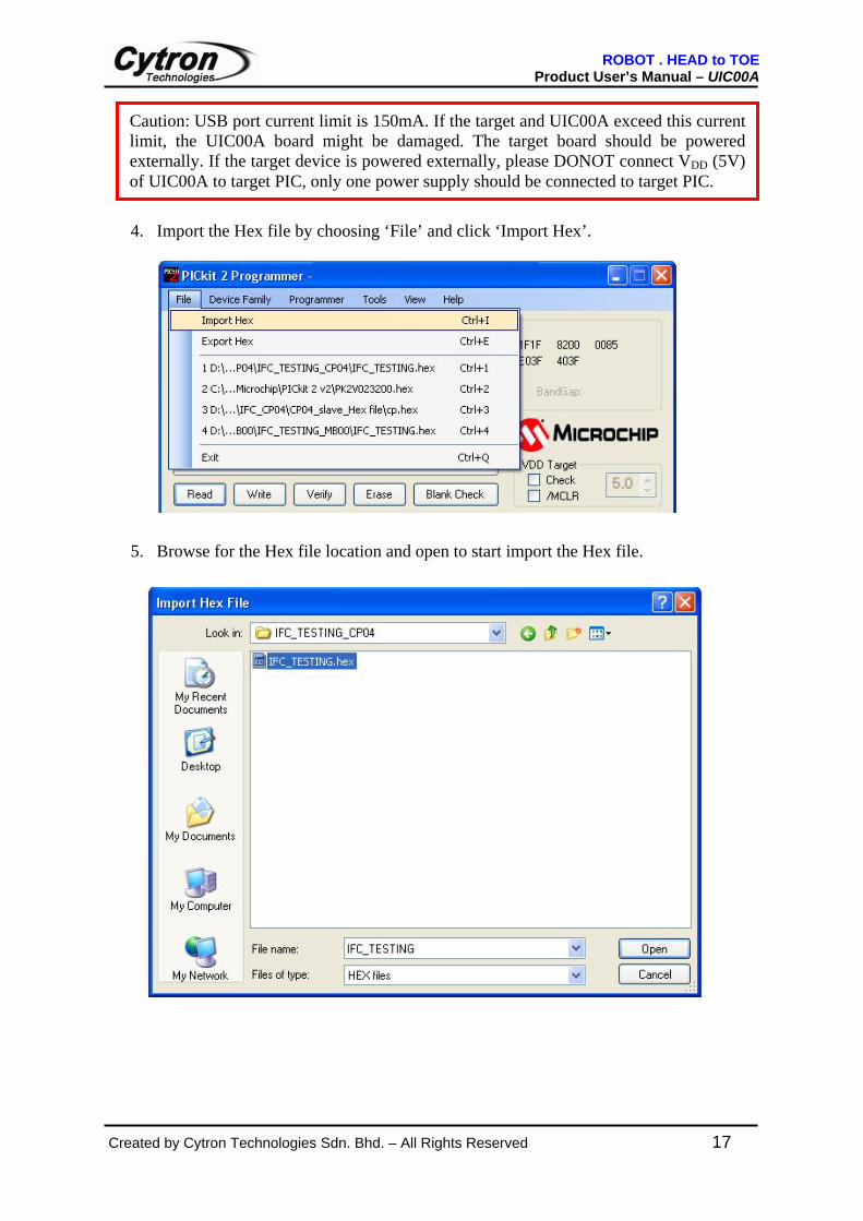
4. Import the Hex file by choosing ‘File’ and click ‘Import Hex’.
5. Browse for the Hex file location and open to start import the Hex file.
Caution: USB port current limit is 150mA. If the target and UIC00A exceed this current limit, the UIC00A board might be damaged. The target board should be powered externally. If the target device is powered externally, please DONOT connect VDD (5V) of UIC00A to target PIC, only one power supply should be connected to target PIC.

ROBOT . HEAD to TOE Product User’s Manual – UIC00A
Created by Cytron Technologies Sdn. Bhd. – All Rights Reserved 18
6. If the Hex code is supported and match with the device, PICkit 2 Programmer will successfully import the Hex code.
7. After Hex file has been successfully imported, the target device can be programmed
by clicking on Write. The PIC will be erased and programmed with the new Hex code imported. The operation status will display on the Status Bar and the status bar will turn to GREEN if writing is successful.

ROBOT . HEAD to TOE Product User’s Manual – UIC00A
Created by Cytron Technologies Sdn. Bhd. – All Rights Reserved 19
8. Push button (on UIC00A main board) is a special feature to load Hex file into the target device. Push button can be used after Programmer>Write on PICkit Button is checked as figure below:
9. After “Write on PICkit Button” is checked, browse for the Hex file location and open to start imported the Hex file.

ROBOT . HEAD to TOE Product User’s Manual – UIC00A
Created by Cytron Technologies Sdn. Bhd. – All Rights Reserved 20
10. Press push button and the Hex file will automatically program into the target device.

ROBOT . HEAD to TOE Product User’s Manual – UIC00A
Created by Cytron Technologies Sdn. Bhd. – All Rights Reserved 21
11. Push button allow user to reload the updated hex file into the target device. After convert any changes in the program into Hex file, press push button again and UIC00A will automatically reload the new Hex file, further program into the target device.
12. Verify function verify the device program to the imported Hex file. Read function is to view the code written to the PIC. The code will be display in the Program Memory and Data EEPROM Memory. If all zero display, it is possible that the target device is code-protected.
ROBOT . HEAD to TOE Product User’s Manual – UIC00A
Created by Cytron Technologies Sdn. Bhd. – All Rights Reserved 22
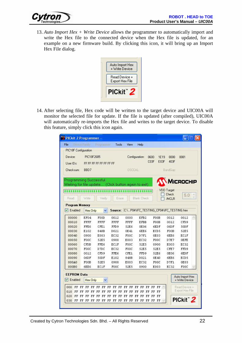
13. Auto Import Hex + Write Device allows the programmer to automatically import and write the Hex file to the connected device when the Hex file is updated, for an example on a new firmware build. By clicking this icon, it will bring up an Import Hex File dialog.
14. After selecting file, Hex code will be written to the target device and UIC00A will monitor the selected file for update. If the file is updated (after compiled), UIC00A will automatically re-imports the Hex file and writes to the target device. To disable this feature, simply click this icon again.

ROBOT . HEAD to TOE Product User’s Manual – UIC00A
Created by Cytron Technologies Sdn. Bhd. – All Rights Reserved 23
15. Old UIC00A’s firmware must updated in order to use with new version of PICkit 2 (2.55 version) software. The PICkit 2 software will prompt user to update the firmware.
• To update the firmware for UIC00A, close PICkit 2 program and download “UIC00A Firmware Updater” from Cytron’s website under UIC00A product page.
• Double click “UIC00A Firmware Updater” and Cytron UIC00A rev1.0
Firmware Updater windows will appear as shown in figure below.

ROBOT . HEAD to TOE Product User’s Manual – UIC00A
Created by Cytron Technologies Sdn. Bhd. – All Rights Reserved 24
• Connect A-type USB connector (one end of USB cable) to USB port at laptop or PC desktop.
• Connect the other end of USB cable (mini) to UIC00A USB port. Green LED
(Power) will turn on. • Click on “Check Hardware”. When the operation is succeeded, Unit ID and
OS Firmware will be displayed as shown in figure below. Make sure only one UIC00A programmer is connected each time.
• UIC00A firmware updater will prompt a warning message if more than one UIC00A is detected at the time. Only one UIC00A programmer can be updated each time.

ROBOT . HEAD to TOE Product User’s Manual – UIC00A
Created by Cytron Technologies Sdn. Bhd. – All Rights Reserved 25
• Click “Download Firmware” to start download new firmware into UIC00A. Wait for around 30 second for the operation to complete.
• After downloading process completed, user can use UIC00A programmer as usual. After updated the firmware, new ID will be assigned and displayed as shown in figure below.
New ID is assigned

ROBOT . HEAD to TOE Product User’s Manual – UIC00A
Created by Cytron Technologies Sdn. Bhd. – All Rights Reserved 26
7.2 Using UIC00A UIC00A can be used in two methods:
1) Program a PIC MCU with the MCU on development board which has been shown in section 5.1.
2) Program a PIC MCU in stand alone mode, shown in section 5.2.
ROBOT . HEAD to TOE Product User’s Manual – UIC00A
Created by Cytron Technologies Sdn. Bhd. – All Rights Reserved 27
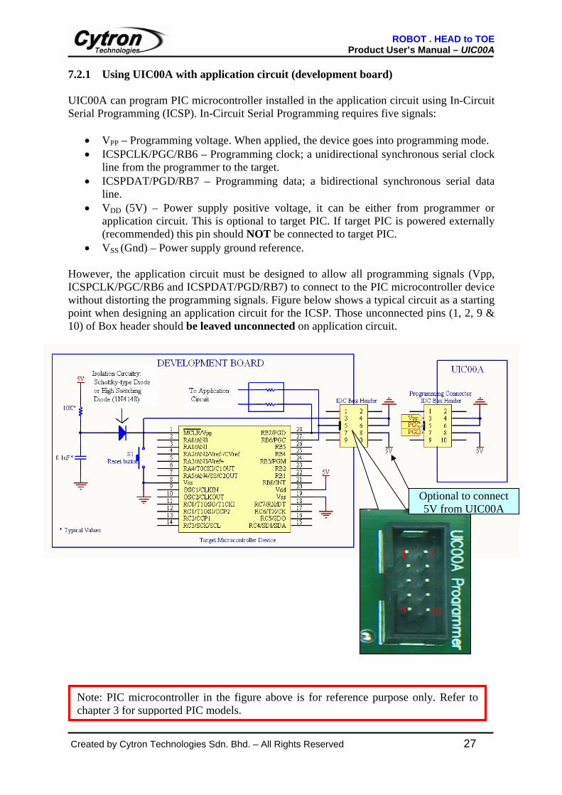
7.2.1 Using UIC00A with application circuit (development board) UIC00A can program PIC microcontroller installed in the application circuit using In-Circuit Serial Programming (ICSP). In-Circuit Serial Programming requires five signals:
• VPP – Programming voltage. When applied, the device goes into programming mode. • ICSPCLK/PGC/RB6 – Programming clock; a unidirectional synchronous serial clock
line from the programmer to the target. • ICSPDAT/PGD/RB7 – Programming data; a bidirectional synchronous serial data
line. • VDD (5V) – Power supply positive voltage, it can be either from programmer or
application circuit. This is optional to target PIC. If target PIC is powered externally (recommended) this pin should NOT be connected to target PIC.
• VSS (Gnd) – Power supply ground reference. However, the application circuit must be designed to allow all programming signals (Vpp, ICSPCLK/PGC/RB6 and ICSPDAT/PGD/RB7) to connect to the PIC microcontroller device without distorting the programming signals. Figure below shows a typical circuit as a starting point when designing an application circuit for the ICSP. Those unconnected pins (1, 2, 9 & 10) of Box header should be leaved unconnected on application circuit.
Note: PIC microcontroller in the figure above is for reference purpose only. Refer to chapter 3 for supported PIC models.
10 9
1 2
Optional to connect 5V from UIC00A

ROBOT . HEAD to TOE Product User’s Manual – UIC00A
Created by Cytron Technologies Sdn. Bhd. – All Rights Reserved 28
Please be aware of:
• During programming mode, VPP voltage will be raised to about 13.25V. It is recommended to isolate the supervisory circuit if interfaces with MCLR pin by using Schottky-type diode or high switching diode (1N4148) to prevent VPP voltage slew rate from slow down and exceeds the rise time in the programming specification (typically 1µs). There should not be capacitive component (capacitor) connected to MCLR directly.
• RB7/PGD or RB6/PGC pin are recommended to use as output controlling non critical
device such as LED, LCD, 7 segments or buzzer. It is recommended to isolated ICSP signals from application circuit by using series resistor (range 220 ohm and above) as shown in figure above. Furthermore, NO capacitive component (capacitor) should be connected to these 2 pins directly.
• During ICSP programming, PIC microcontroller needs to be powered. It is
recommended to power the target externally; USB is not able to support large power usage. If target PIC is powered externally VDD (5V) should NOT be connected to target PIC.
• The minimum connections from UIC00A to target board or PIC are four. These
include Vpp, PGD, PGC and Vss (Gnd).
• Thus, the 5V from UIC00A is an optional connection. If user is powering up the target board with external power, this pin is not necessary to connect from UIC00A to target board.
• For usage example, please refer to DIY Project (PR7 onwards) in Cytron website.

ROBOT . HEAD to TOE Product User’s Manual – UIC00A
Created by Cytron Technologies Sdn. Bhd. – All Rights Reserved 29
7.2.2 Using UIC00A with UIC-S (optional, buy separately) UIC-S is an optional socket that can be used with UIC00A to program several types of PIC microcontroller. Below are the steps of using the UIC-S and method to connect it to UIC00A:
1. Connect one side of the rainbow cable (programming cable) to box header of UIC00A board and the other side to box header of UIC-S as shown in section 5.2.
2. LED PWR of UIC-S will ON (once USB connection from UIC00A to computer or
laptop is connected) indicate that the board is working correctly.
3. After that, turn the slide switch (on UIC-S) either to 18 pins or 28/40 pins (according to the PIC microcontroller that you want to program).
4. Download the program as shown in section 7.

ROBOT . HEAD to TOE Product User’s Manual – UIC00A
Created by Cytron Technologies Sdn. Bhd. – All Rights Reserved 30
7.3 Troubleshooting Following section discuss error messages from PICkit 2 programming software, possible root causes and methods to fix it.
a. Window (right bottom corner) show “Unrecognized USB device” when UIC00A is connected to USB port. i) Please check the connection of your USB cable (computer and also UIC00A). ii) Please try to use other USB cable. iii) Please try other USB port on computer. iv) Please try on other computer. v) If the problem still occur, please contact Cytron at [email protected]
b. Status Window shows: “PICkit 2 not found. Check USB connections and use Tools-
>Check Communication to retry”. i) Please reconnect the UIC00A to USB port and try again. ii) Driver might not be installed properly, uninstall driver and install again. iii) User might need to update Operating System. Please refer to step 14 of chapter 7. iv) Check the power LED on UIC00A. If it is Off, UIC00A have hardware problem.
c. Status Window shows: “No device detected” while Device shows: “No Device
Found”. i) Please ensure the target PIC is powered with typical voltage of 5V for Vcc. ii) Please ensure the PGC and PCD is connected to correct pin on target PIC. iii) Please ensure the Vss (Gnd) of UIC00A and target PIC is common (connected).
d. Device shows: “Unsupported part”.
i) Please ensure the Vss (Gnd) of target PIC is connected. ii) Please ensure the target PIC is in supported list.
e. A small message window shows: “PICkit 2 VPP voltage level error. Check target &
retry operation”.
i) Check MCLR pin of target PIC, it must not pulled to ground during programming.
ii) Check MCLR pin of target PIC, there should not be capacitor connected.
f. When UIC-S is plug in Green LED at UIC00A is ON but Green LED and UIC-S is not ON. i) UIC00A on board fuse is burned, there might be some place shorted causing this.
Please send back for repair, service shipping charges will be required. ii) PIC chip spoilt causing short at Vdd (5V) and Vss (Gnd). Change PIC. iii) Check the back of UIC-S for any wire or dirt which might be causing the short.

ROBOT . HEAD to TOE Product User’s Manual – UIC00A
Created by Cytron Technologies Sdn. Bhd. – All Rights Reserved 31
For any feedbacks and inquiries, please send an email to [email protected] 8. WARRANTY
Product warranty is valid for 6 months. Warranty only applies to manufacturing defect. Damage caused by misuse is not covered under warranty. Warranty does not cover freight cost for both ways.
Prepared by Cytron Technologies Sdn. Bhd.
19, Jalan Kebudayaan 1A, Taman Universiti,
81300 Skudai, Johor, Malaysia.
Tel: +607-521 3178 Fax: +607-521 1861
URL: www.cytron.com.my