cytron usb pic programmer v2009 up00b · cytron usb pic programmer v2009 up00b user’s manual v1.0...
TRANSCRIPT
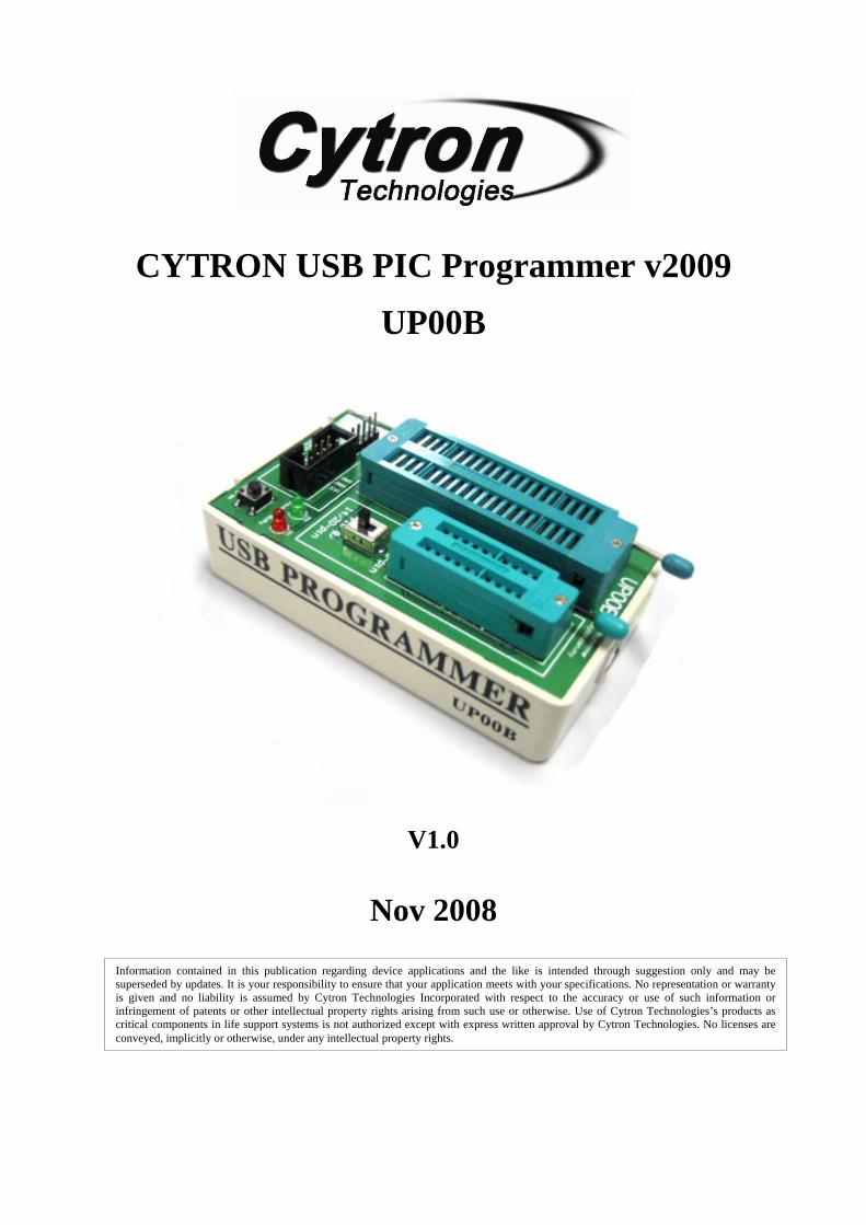
CYTRON USB PIC Programmer v2009
UP00B
User’s Manual
V1.0
Nov 2008
Information contained in this publication regarding device applications and the like is intended through suggestion only and may be superseded by updates. It is your responsibility to ensure that your application meets with your specifications. No representation or warranty is given and no liability is assumed by Cytron Technologies Incorporated with respect to the accuracy or use of such information or infringement of patents or other intellectual property rights arising from such use or otherwise. Use of Cytron Technologies’s products as critical components in life support systems is not authorized except with express written approval by Cytron Technologies. No licenses are conveyed, implicitly or otherwise, under any intellectual property rights.
ROBOT . HEAD to TOE Product User’s Manual – UP00B
Created by Cytron Technologies Sdn. Bhd. – All Rights Reserved
Index
1. Introduction and Overview 1
2. Packaging List 2
3. Supported PICs 3
3.1 Supported PICs using ZIF Socket 3
3.2 Supported PICs using ICSP 4
4. Board Layout 5
5. Installation (Software) 7
5.1 Install from CD 7
5.2 Download setup file from Cytron’s website 7
5.3 PICkit 2 Programmer setup procedures 8
6. Installation (Hardware) 12
6.1 Connecting UP00B with USB B Type cable 12
6.2 Connecting UP00B with board via connector 13
6.3 Plugging the PIC Microcontroller 17
7. Getting Started 21
8. Warranty 32
ROBOT . HEAD to TOE Product User’s Manual – UP00B
Created by Cytron Technologies Sdn. Bhd. – All Rights Reserved
1
1. INTRODUCTION AND OVERVIEW UP00B is the enhanced version of UP00A. As PIC MCU is gaining its popularity in market for student and hobbyist, more low cost and user friendly programmer is needed. Previous USB PIC Programmer, UP00A is obsolete because it cannot support Windows Vista, fail to program many new PIC MCU, further the firmware is not upgradeable. Hence, UP00B is now introduced to you! It comes with two ZIP sockets to offer program loading to 8 pin, 18 pin, 28 pin and 40 pin PIC MCU (8 bit) by using Microchip PICKit2 software. It offers a low cost yet convenience USB PIC Programmer to user. Loading program to PIC MCU will be as easy as 1, 2, 3. It has been designed with capabilities and features as below:
• USB powered, no extra power needed to load program • Two ZIF sockets (20 pins and 40 pins) to ease program loading process • Support most 8pin, 18pin, 28pin and 40pin PDIP 8 bit PIC MCU • Support windows XP and Vista • Support Intel and AMD based system • Support Laptop and desktop PC

ROBOT . HEAD to TOE Product User’s Manual – UP00B
Created by Cytron Technologies Sdn. Bhd. – All Rights Reserved
2
2. PACKAGING LIST Please check the parts and components according to the packing list. If there are any parts missing, please contact us at [email protected] immediately. 1. 1 x USB Programmer UP00B
2. 1 x USB cable (B type) 3. 1 x Software Installation and User’s Manual CD
4. 1 x Programming cable (rainbow cable)
4
1
2
3

ROBOT . HEAD to TOE Product User’s Manual – UP00B
Created by Cytron Technologies Sdn. Bhd. – All Rights Reserved
3
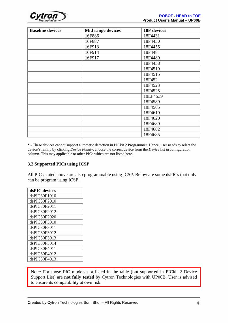
3. SUPPORTED PICs UP00B is compatible with Microchip PICkit 2 Programmer software. It has been tested to load program and below are the PIC models that has being tested using UP00B. 3.1 Supported PICs using ZIF Sockets Baseline devices Midrange devices 18F devices *12F508 *16F506 18F1220 *12F509 16F610 18F1230 12F615 16HV610 18F1320 12HV615 16F616 18F1330 12F609 16HV616 18F2220 12HV609 16F627 18F2320 12F629 16F627A 18F2331 12F635 16F628A 18F2410 12F683 16F630 18F2420 16F631 18F2423 16F636 18F2431 16F648A 18F2450 16F676 18F2455 16F677 18F2458 16F684 18F248 16F685 18F2480 16F687 18F2510 16F688 18F2515 16F689 18F252 16F690 18F2520 16F716 18F2523 16F72 18F2525 16F73 18F2550 16F737 18LF2550 16F74 18F2553 16F747 18F258 16F76 18F2580 16F767 18F2585 16F77 18F2610 16F777 18F2620 16HV785 18F2680 16F785 18F2682 16F818 18F4220 16F877 18F4221 16F870 18F4320 16F871 18F4321 16F872 18F4331 16F874A 18F4410 16F88 18F442 16F882 18F4420 16F883 18F4423
ROBOT . HEAD to TOE Product User’s Manual – UP00B
Created by Cytron Technologies Sdn. Bhd. – All Rights Reserved
4
Baseline devices Mid range devices 18F devices 16F886 18F4431 16F887 18F4450 16F913 18F4455 16F914 18F448 16F917 18F4480 18F4458 18F4510 18F4515 18F452 18F4523 18F4525 18LF4539 18F4580 18F4585 18F4610 18F4620 18F4680 18F4682 18F4685
* - These devices cannot support automatic detection in PICkit 2 Programmer. Hence, user needs to select the device’s family by clicking Device Family, choose the correct device from the Device list in configuration column. This may applicable to other PICs which are not listed here. 3.2 Supported PICs using ICSP All PICs stated above are also programmable using ICSP. Below are some dsPICs that only can be program using ICSP. dsPIC devices dsPIC30F1010 dsPIC30F2010 dsPIC30F2011 dsPIC30F2012 dsPIC30F2020 dsPIC30F3010 dsPIC30F3011 dsPIC30F3012 dsPIC30F3013 dsPIC30F3014 dsPIC30F4011 dsPIC30F4012 dsPIC30F4013
Note: For those PIC models not listed in the table (but supported in PICkit 2 Device Support List) are not fully tested by Cytron Technologies with UP00B. User is advised to ensure its compatibility at own risk.

ROBOT . HEAD to TOE Product User’s Manual – UP00B
Created by Cytron Technologies Sdn. Bhd. – All Rights Reserved
5
4. BOARD LAYOUT
Label Function
A ZIF Socket 20 pins
B ZIF Socket 40 pins
C Switch selector for PIC pins of ZIF Socket 20 pins
D Busy LED
E Power LED
F Program Button
G Connector for ICSP
A
B
CD
E
G
F
ROBOT . HEAD to TOE Product User’s Manual – UP00B
Created by Cytron Technologies Sdn. Bhd. – All Rights Reserved
6
A – ZIF Socket 20-pin is used to place 8, 14, 18 and 20 pins PIC during load program. B – ZIF Socket 40-pin is used to place 28 and 40 pins PIC during load program. C – Selector for ZIF Socket 20-pin. If users want to program 18-pin PIC, push this
selector to up position. If users needed to program 8, 14 and 20-pin PIC, push this selector to down position.
D – Busy LED. This LED is red in color. It will turn on when there is process going on in
UP00B. For example, once PIC is placed in ZIF Socket, and PICkit2 programmer detected it, Busy LED will turn ON for a while. Same goes while PICkit2 Programmer Read, Write, Verify, Erase and Blank Check the program in PIC.
E – Power LED. This LED is green in color. It will turn ON once power is inserted to
UP00B. When UP00B is connected to PC via USB B Type, this LED should turn ON. F – Program Button. Press this button if user wants to program the PIC. It can only work
after everything is connected and HEX Code imported. This button has the same function with clicking the ‘Write’ button in PICkit2 Programmer software.
G – Connectors for ICSP. These connectors are used to connect UP00B with board or any
microcontroller for cases where user cannot place the PIC to ZIF Socket (eg: PIC is soldered directly to the board). UP00B provide two types of connector. User may choose either to use 5 ways pin header connector or 2x5 H type box header connector.
ROBOT . HEAD to TOE Product User’s Manual – UP00B
Created by Cytron Technologies Sdn. Bhd. – All Rights Reserved
7
5. INSTALLATION (SOFTWARE) The programmer software for UP00B is Microchip PICkit 2 Programmer software. With the help of pictures and some simple instructions, the following section will guide user to install this software. 5.1 Install from CD
1. Place UP00B CD in to computer or laptop CD drive.
2. Browse to folder “UP00B setup”.
3. Double click “setup” to run the installation wizard. 5.2 Download setup file from Cytron’s website
1. User may download the setup file from Cytron’s website: http://www.cytron.com.my/suppMaterial/UP00B_setup.zip
2. After finish downloading, unzip the file and click any from the two icons to launch the setup.
ROBOT . HEAD to TOE Product User’s Manual – UP00B
Created by Cytron Technologies Sdn. Bhd. – All Rights Reserved
8
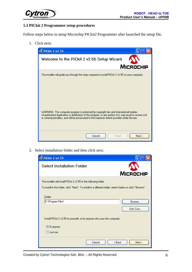
5.3 PICkit 2 Programmer setup procedures Follow steps below to setup Microchip PICkit2 Programmer after launched the setup file.
1. Click next.
2. Select installation folder and then click next.
ROBOT . HEAD to TOE Product User’s Manual – UP00B
Created by Cytron Technologies Sdn. Bhd. – All Rights Reserved
9
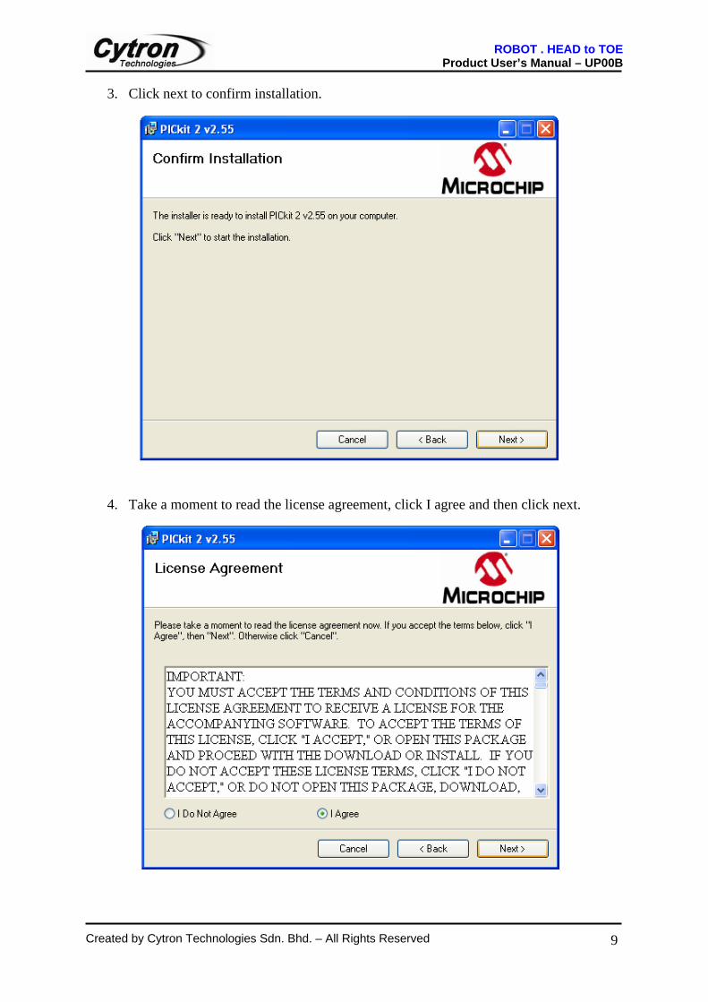
3. Click next to confirm installation.
4. Take a moment to read the license agreement, click I agree and then click next.
ROBOT . HEAD to TOE Product User’s Manual – UP00B
Created by Cytron Technologies Sdn. Bhd. – All Rights Reserved
10
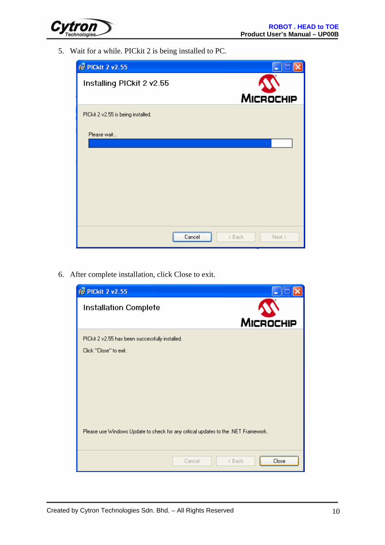
5. Wait for a while. PICkit 2 is being installed to PC.
6. After complete installation, click Close to exit.
ROBOT . HEAD to TOE Product User’s Manual – UP00B
Created by Cytron Technologies Sdn. Bhd. – All Rights Reserved
11
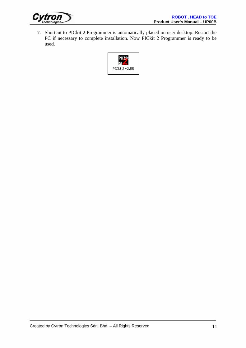
7. Shortcut to PICkit 2 Programmer is automatically placed on user desktop. Restart the PC if necessary to complete installation. Now PICkit 2 Programmer is ready to be used.
ROBOT . HEAD to TOE Product User’s Manual – UP00B
Created by Cytron Technologies Sdn. Bhd. – All Rights Reserved
12
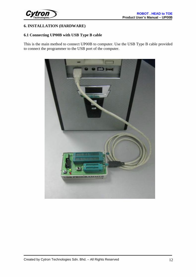
6. INSTALLATION (HARDWARE) 6.1 Connecting UP00B with USB Type B cable This is the main method to connect UP00B to computer. Use the USB Type B cable provided to connect the programmer to the USB port of the computer.
ROBOT . HEAD to TOE Product User’s Manual – UP00B
Created by Cytron Technologies Sdn. Bhd. – All Rights Reserved
13
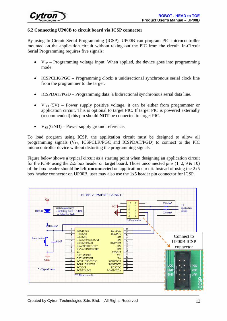
6.2 Connecting UP00B to circuit board via ICSP connector
By using In-Circuit Serial Programming (ICSP), UP00B can program PIC microcontroller mounted on the application circuit without taking out the PIC from the circuit. In-Circuit Serial Programming requires five signals:
• VPP – Programming voltage input. When applied, the device goes into programming mode.
• ICSPCLK/PGC – Programming clock; a unidirectional synchronous serial clock line from the programmer to the target.
• ICSPDAT/PGD – Programming data; a bidirectional synchronous serial data line.
• VDD (5V) – Power supply positive voltage, it can be either from programmer or
application circuit. This is optional to target PIC. If target PIC is powered externally (recommended) this pin should NOT be connected to target PIC.
• VSS (GND) – Power supply ground reference.
To load program using ICSP, the application circuit must be designed to allow all programming signals (VPP, ICSPCLK/PGC and ICSPDAT/PGD) to connect to the PIC microcontroller device without distorting the programming signals. Figure below shows a typical circuit as a starting point when designing an application circuit for the ICSP using the 2x5 box header on target board. Those unconnected pins (1, 2, 9 & 10) of the box header should be left unconnected on application circuit. Instead of using the 2x5 box header connector on UP00B, user may also use the 1x5 header pin connector for ICSP.
Connect to UP00B ICSP
connector
ROBOT . HEAD to TOE Product User’s Manual – UP00B
Created by Cytron Technologies Sdn. Bhd. – All Rights Reserved
14
Please beware of:
• During programming mode, VPP voltage will be raised to about 13.25V. It is recommended to isolate the supervisory circuit if interfaces with MCLR pin by using Schottky-type diode or high switching diode (1N4148) to prevent VPP voltage slew rate from slow down and exceeds the rise time in the programming specification (typically 1µs). There should not be capacitive component (capacitor) connected to MCLR directly.
• RB7/PGD or RB6/PGC pin are recommended to use as output controlling non critical
device such as LED, LCD, 7 segments or buzzer. It is recommended to isolated ICSP signals from application circuit by using series resistor (range 220 ohm and above) as shown in the above figure. Furthermore, NO capacitive component (capacitor) should be connected to these 2 pins directly.
• During ICSP programming, PIC microcontroller needs to be powered. It is
recommended to power the target externally. USB is not able to support large power usage. If target PIC is powered externally, VDD (5V) should NOT be connected to target PIC.
• The minimum connections from UP00B to target board or PIC are four. These
include VPP, PGD, PGC and VSS (Gnd).
• Thus, the 5V from UP00B is an optional connection. If user is powering up the target board with external power, this pin is not necessary to connect from UP00B to the target board.
Note: PIC microcontroller in the figure above is for reference purpose only. Hence the actual pin diagram may differ for different PIC model. Refer to chapter 3 for supported PIC models.
Note: ONLY connect to ONE CONNECTOR at the same time. DO NOT tries to use both connectors to program two PICs simultaneously.
Note: Please refer to the In-Circuit Serial Programming (ICSP) section in the datasheet of the PIC that you want to program for further information and special caution if any.
ROBOT . HEAD to TOE Product User’s Manual – UP00B
Created by Cytron Technologies Sdn. Bhd. – All Rights Reserved
15
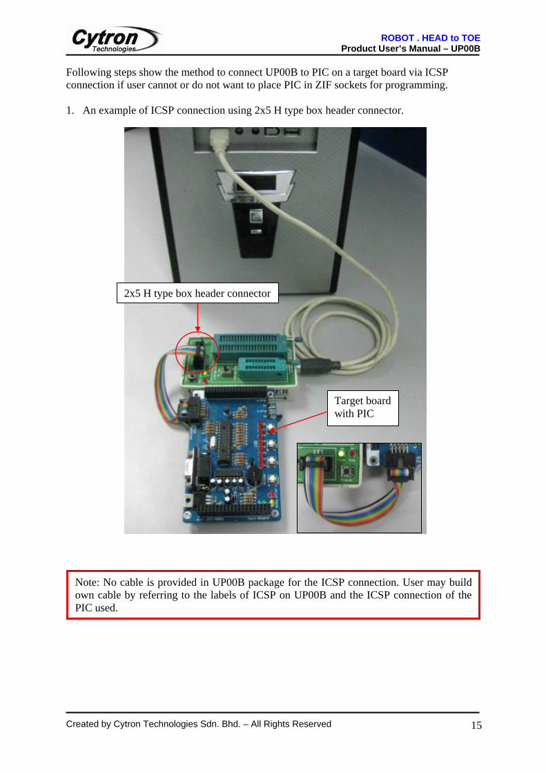
Following steps show the method to connect UP00B to PIC on a target board via ICSP connection if user cannot or do not want to place PIC in ZIF sockets for programming. 1. An example of ICSP connection using 2x5 H type box header connector.
Note: No cable is provided in UP00B package for the ICSP connection. User may build own cable by referring to the labels of ICSP on UP00B and the ICSP connection of the PIC used.
Target board with PIC
2x5 H type box header connector
ROBOT . HEAD to TOE Product User’s Manual – UP00B
Created by Cytron Technologies Sdn. Bhd. – All Rights Reserved
16
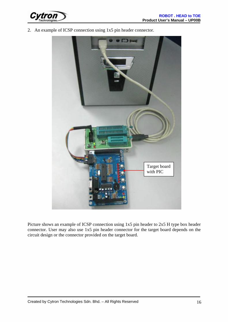
2. An example of ICSP connection using 1x5 pin header connector.
Picture shows an example of ICSP connection using 1x5 pin header to 2x5 H type box header connector. User may also use 1x5 pin header connector for the target board depends on the circuit design or the connector provided on the target board.
1x5 pin header connector
Target board with PIC
ROBOT . HEAD to TOE Product User’s Manual – UP00B
Created by Cytron Technologies Sdn. Bhd. – All Rights Reserved
17
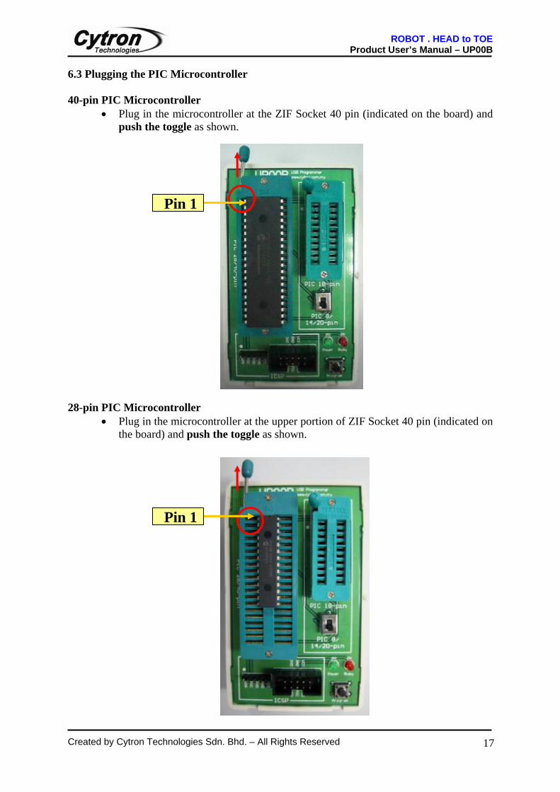
6.3 Plugging the PIC Microcontroller 40-pin PIC Microcontroller
• Plug in the microcontroller at the ZIF Socket 40 pin (indicated on the board) and push the toggle as shown.
28-pin PIC Microcontroller
• Plug in the microcontroller at the upper portion of ZIF Socket 40 pin (indicated on the board) and push the toggle as shown.
Pin 1
Pin 1
ROBOT . HEAD to TOE Product User’s Manual – UP00B
Created by Cytron Technologies Sdn. Bhd. – All Rights Reserved
18
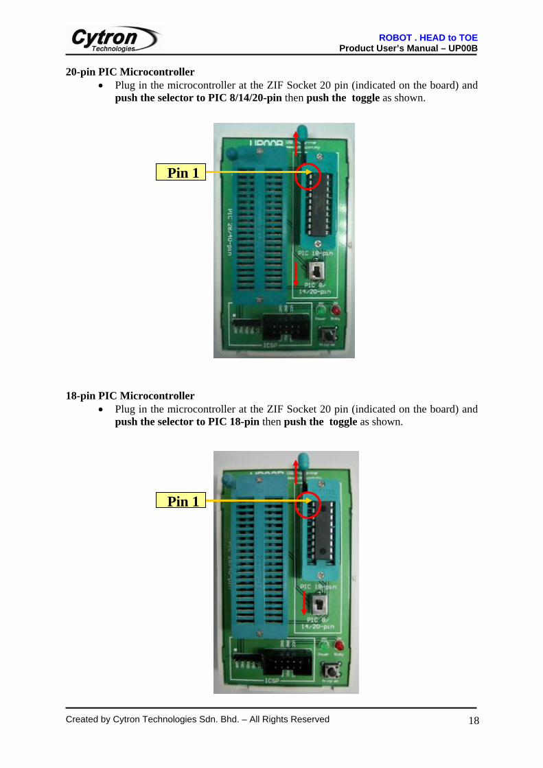
20-pin PIC Microcontroller • Plug in the microcontroller at the ZIF Socket 20 pin (indicated on the board) and
push the selector to PIC 8/14/20-pin then push the toggle as shown.
18-pin PIC Microcontroller
• Plug in the microcontroller at the ZIF Socket 20 pin (indicated on the board) and push the selector to PIC 18-pin then push the toggle as shown.
Pin 1
Pin 1
ROBOT . HEAD to TOE Product User’s Manual – UP00B
Created by Cytron Technologies Sdn. Bhd. – All Rights Reserved
19
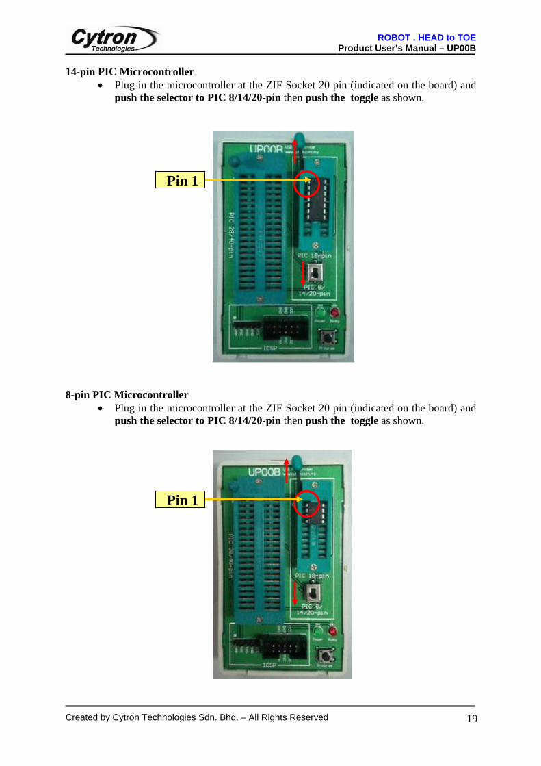
14-pin PIC Microcontroller • Plug in the microcontroller at the ZIF Socket 20 pin (indicated on the board) and
push the selector to PIC 8/14/20-pin then push the toggle as shown.
8-pin PIC Microcontroller
• Plug in the microcontroller at the ZIF Socket 20 pin (indicated on the board) and push the selector to PIC 8/14/20-pin then push the toggle as shown.
Pin 1
Pin 1
ROBOT . HEAD to TOE Product User’s Manual – UP00B
Created by Cytron Technologies Sdn. Bhd. – All Rights Reserved
20
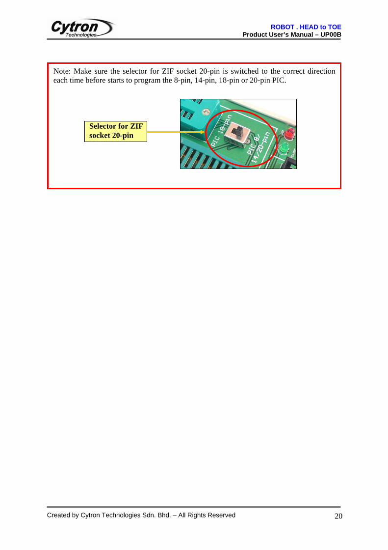
Note: Make sure the selector for ZIF socket 20-pin is switched to the correct direction each time before starts to program the 8-pin, 14-pin, 18-pin or 20-pin PIC.
Selector for ZIF socket 20-pin
ROBOT . HEAD to TOE Product User’s Manual – UP00B
Created by Cytron Technologies Sdn. Bhd. – All Rights Reserved
21
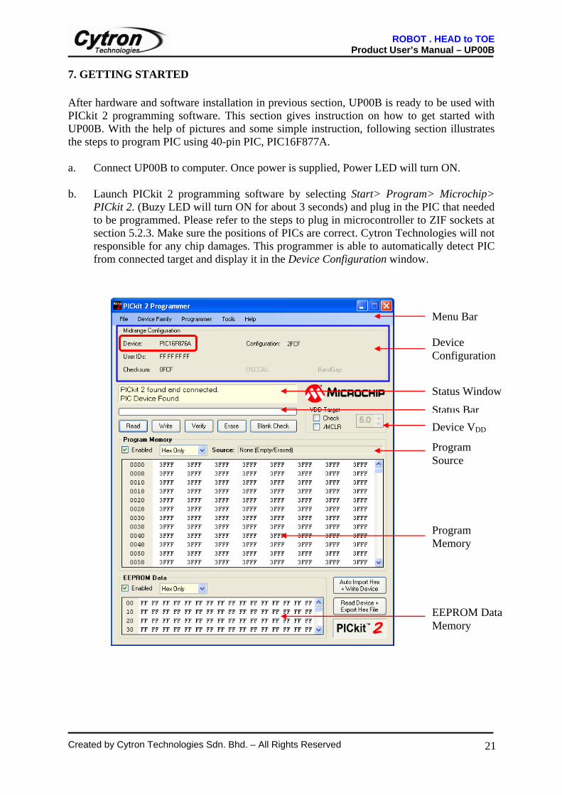
7. GETTING STARTED After hardware and software installation in previous section, UP00B is ready to be used with PICkit 2 programming software. This section gives instruction on how to get started with UP00B. With the help of pictures and some simple instruction, following section illustrates the steps to program PIC using 40-pin PIC, PIC16F877A. a. Connect UP00B to computer. Once power is supplied, Power LED will turn ON. b. Launch PICkit 2 programming software by selecting Start> Program> Microchip>
PICkit 2. (Buzy LED will turn ON for about 3 seconds) and plug in the PIC that needed to be programmed. Please refer to the steps to plug in microcontroller to ZIF sockets at section 5.2.3. Make sure the positions of PICs are correct. Cytron Technologies will not responsible for any chip damages. This programmer is able to automatically detect PIC from connected target and display it in the Device Configuration window.
Menu Bar
Device Configuration
Status WindowStatus Bar
Program Source
Device VDD
Program Memory
EEPROM Data Memory
ROBOT . HEAD to TOE Product User’s Manual – UP00B
Created by Cytron Technologies Sdn. Bhd. – All Rights Reserved
22
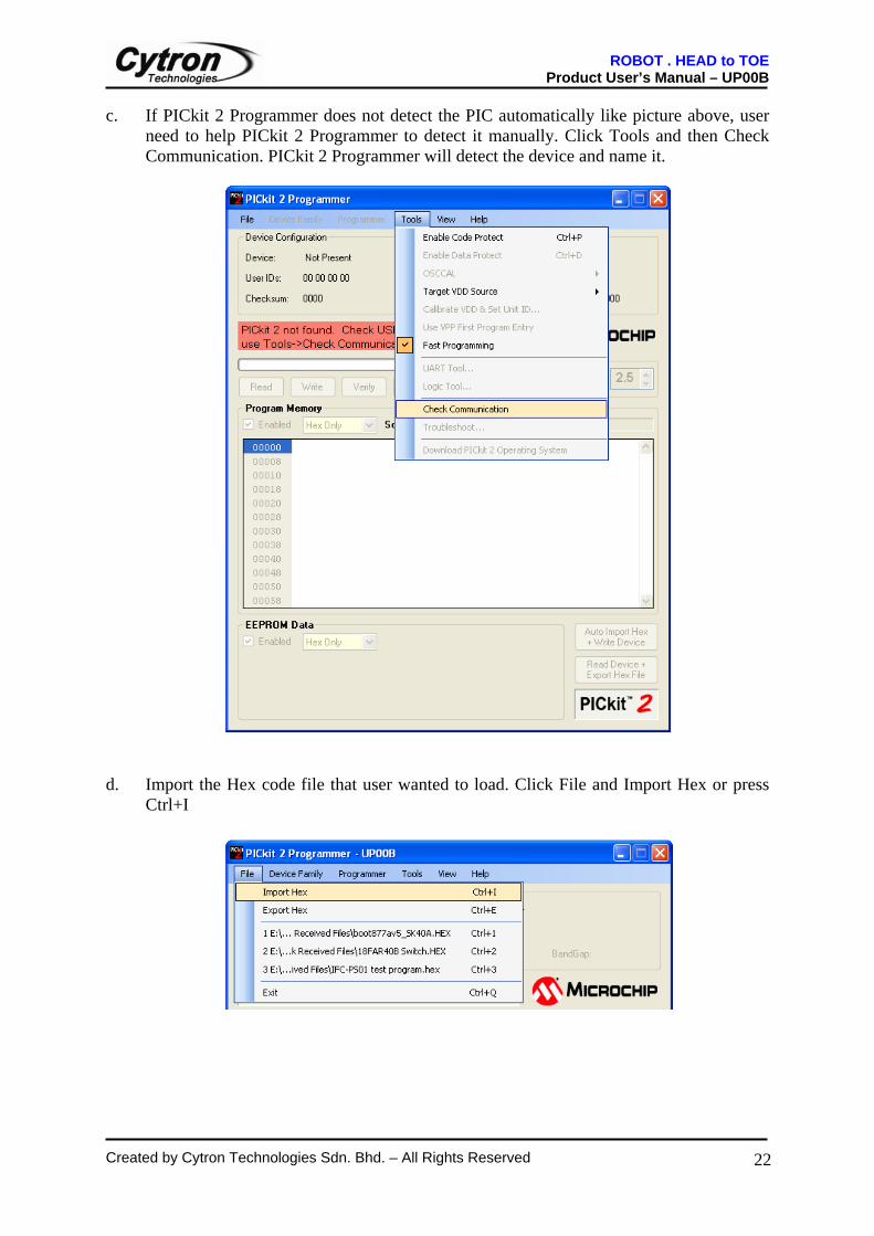
c. If PICkit 2 Programmer does not detect the PIC automatically like picture above, user need to help PICkit 2 Programmer to detect it manually. Click Tools and then Check Communication. PICkit 2 Programmer will detect the device and name it.
d. Import the Hex code file that user wanted to load. Click File and Import Hex or press
Ctrl+I
ROBOT . HEAD to TOE Product User’s Manual – UP00B
Created by Cytron Technologies Sdn. Bhd. – All Rights Reserved
23
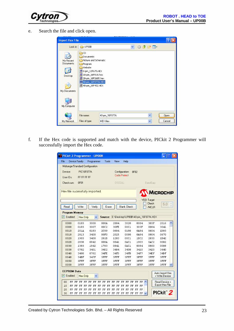
e. Search the file and click open. f. If the Hex code is supported and match with the device, PICkit 2 Programmer will
successfully import the Hex code.
ROBOT . HEAD to TOE Product User’s Manual – UP00B
Created by Cytron Technologies Sdn. Bhd. – All Rights Reserved
24
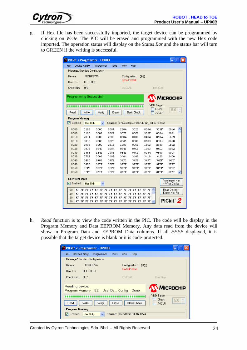
g. If Hex file has been successfully imported, the target device can be programmed by clicking on Write. The PIC will be erased and programmed with the new Hex code imported. The operation status will display on the Status Bar and the status bar will turn to GREEN if the writing is successful.
h. Read function is to view the code written in the PIC. The code will be display in the
Program Memory and Data EEPROM Memory. Any data read from the device will show in Program Data and EEPROM Data columns. If all FFFF displayed, it is possible that the target device is blank or it is code-protected.
ROBOT . HEAD to TOE Product User’s Manual – UP00B
Created by Cytron Technologies Sdn. Bhd. – All Rights Reserved
25
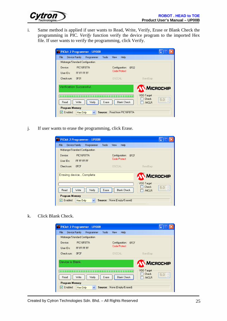
i. Same method is applied if user wants to Read, Write, Verify, Erase or Blank Check the programming in PIC. Verify function verify the device program to the imported Hex file. If user wants to verify the programming, click Verify.
j. If user wants to erase the programming, click Erase. k. Click Blank Check.
ROBOT . HEAD to TOE Product User’s Manual – UP00B
Created by Cytron Technologies Sdn. Bhd. – All Rights Reserved
26
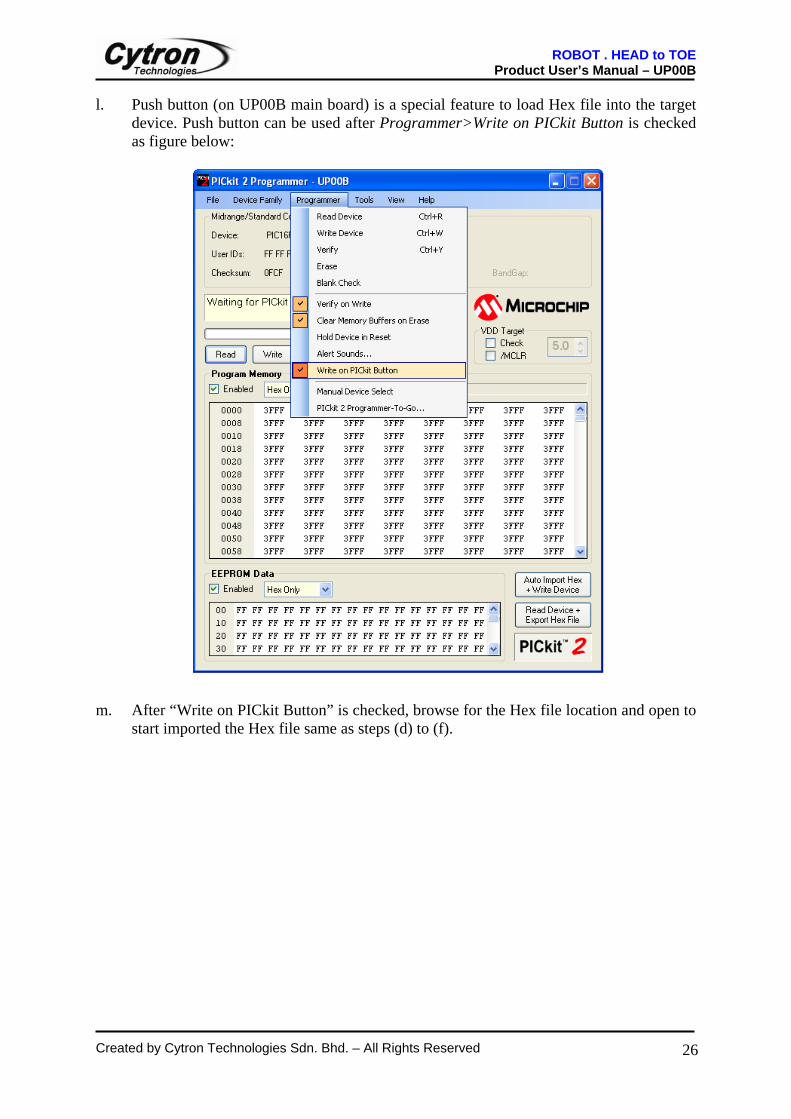
l. Push button (on UP00B main board) is a special feature to load Hex file into the target device. Push button can be used after Programmer>Write on PICkit Button is checked as figure below:
m. After “Write on PICkit Button” is checked, browse for the Hex file location and open to
start imported the Hex file same as steps (d) to (f).
ROBOT . HEAD to TOE Product User’s Manual – UP00B
Created by Cytron Technologies Sdn. Bhd. – All Rights Reserved
27
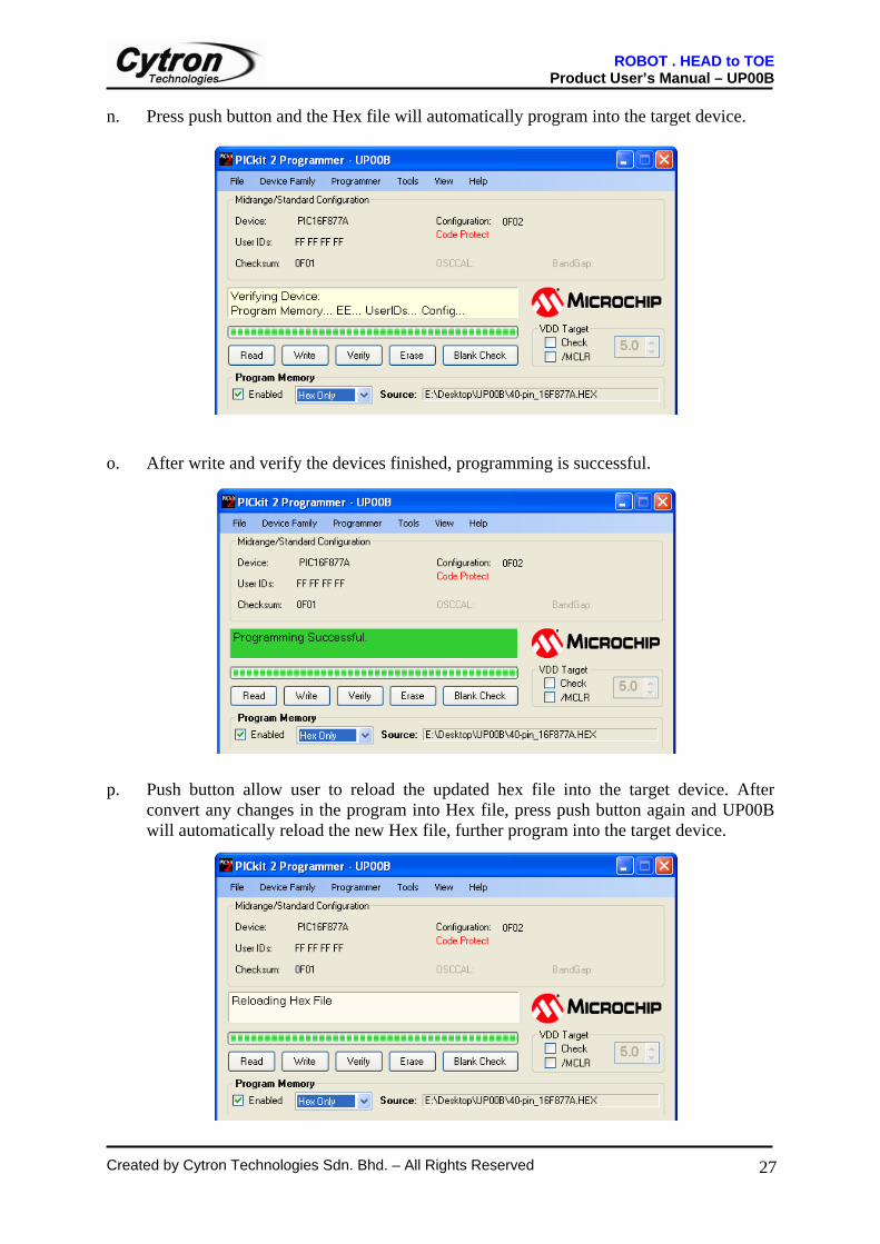
n. Press push button and the Hex file will automatically program into the target device. o. After write and verify the devices finished, programming is successful. p. Push button allow user to reload the updated hex file into the target device. After
convert any changes in the program into Hex file, press push button again and UP00B will automatically reload the new Hex file, further program into the target device.
ROBOT . HEAD to TOE Product User’s Manual – UP00B
Created by Cytron Technologies Sdn. Bhd. – All Rights Reserved
28
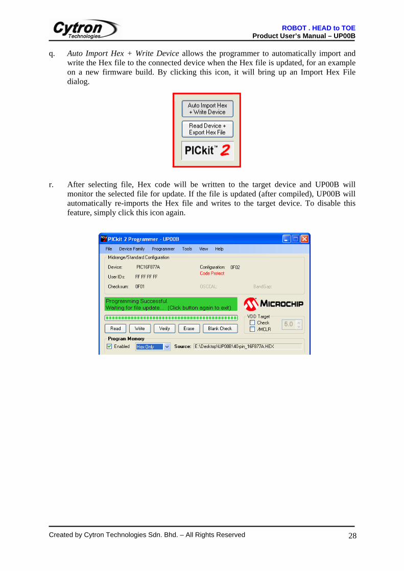
q. Auto Import Hex + Write Device allows the programmer to automatically import and write the Hex file to the connected device when the Hex file is updated, for an example on a new firmware build. By clicking this icon, it will bring up an Import Hex File dialog.
r. After selecting file, Hex code will be written to the target device and UP00B will
monitor the selected file for update. If the file is updated (after compiled), UP00B will automatically re-imports the Hex file and writes to the target device. To disable this feature, simply click this icon again.
ROBOT . HEAD to TOE Product User’s Manual – UP00B
Created by Cytron Technologies Sdn. Bhd. – All Rights Reserved
29
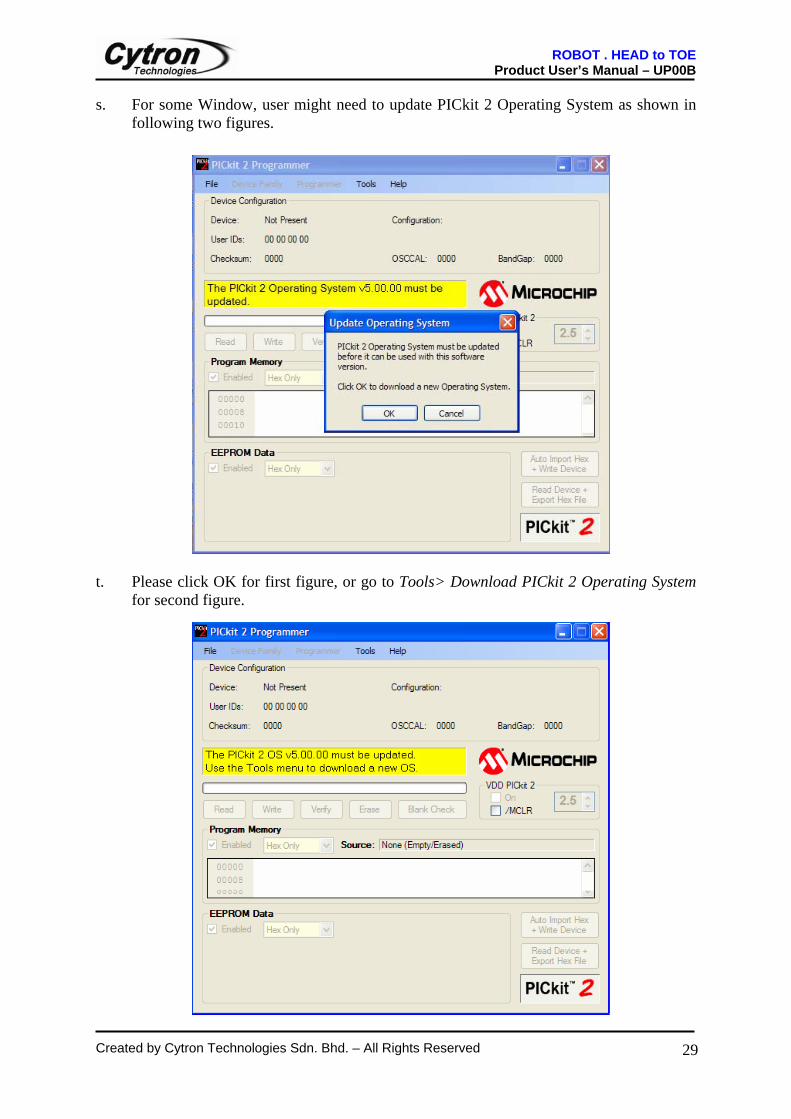
s. For some Window, user might need to update PICkit 2 Operating System as shown in following two figures.
t. Please click OK for first figure, or go to Tools> Download PICkit 2 Operating System
for second figure.
ROBOT . HEAD to TOE Product User’s Manual – UP00B
Created by Cytron Technologies Sdn. Bhd. – All Rights Reserved
30
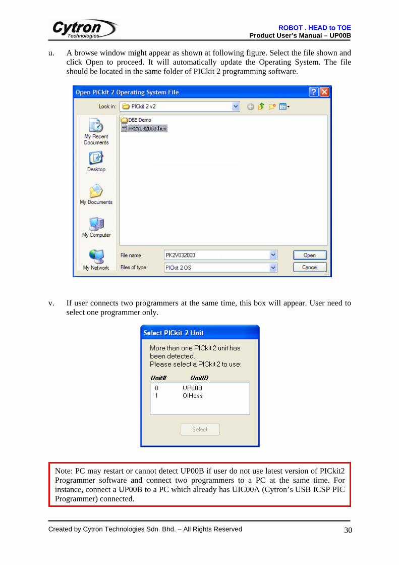
u. A browse window might appear as shown at following figure. Select the file shown and click Open to proceed. It will automatically update the Operating System. The file should be located in the same folder of PICkit 2 programming software.
v. If user connects two programmers at the same time, this box will appear. User need to
select one programmer only.
Note: PC may restart or cannot detect UP00B if user do not use latest version of PICkit2 Programmer software and connect two programmers to a PC at the same time. For instance, connect a UP00B to a PC which already has UIC00A (Cytron’s USB ICSP PIC Programmer) connected.
ROBOT . HEAD to TOE Product User’s Manual – UP00B
Created by Cytron Technologies Sdn. Bhd. – All Rights Reserved
31
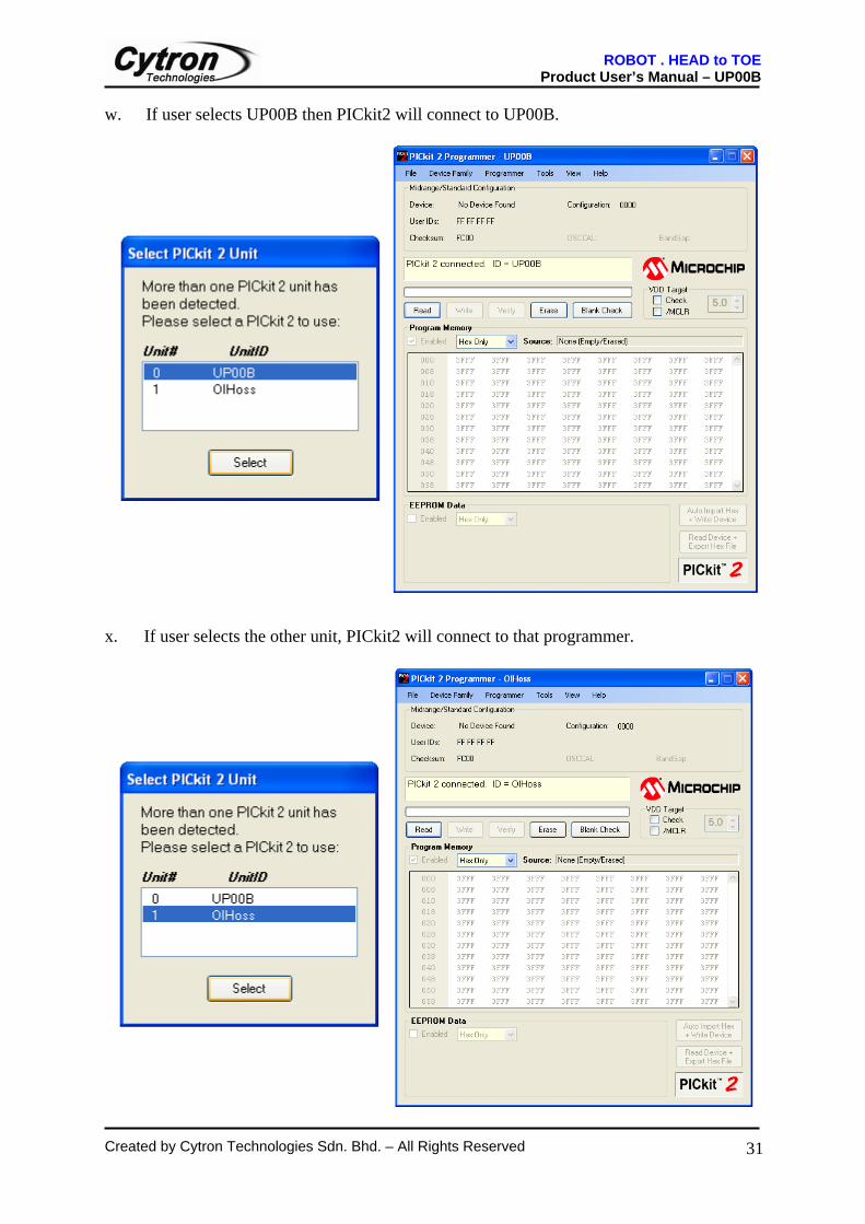
w. If user selects UP00B then PICkit2 will connect to UP00B. x. If user selects the other unit, PICkit2 will connect to that programmer.
ROBOT . HEAD to TOE Product User’s Manual – UP00B
Created by Cytron Technologies Sdn. Bhd. – All Rights Reserved
32
7. WARRANTY
Product warranty is valid for 6 months. Warranty only applies to manufacturing defect. Damage caused by mis-use is not covered under warranty. Warranty does not cover freight cost for both ways.
Prepared by Cytron Technologies Sdn. Bhd.
19, Jalan Kebudayaan 1A, Taman Universiti,
81300 Skudai, Johor, Malaysia.
Tel: +607-521 3178 Fax: +607-521 1861
URL: www.cytron.com.my