type 81 ‘tribal class’ frigate h.m.s. zuluatlanticmodels.net/onewebmedia/zulu350.pdf · type 81...
TRANSCRIPT

Type 81 ‘Tribal Class’ Frigate
H.M.S. ZULU1964-1984
1/350 ScaleThe design of the Type 81 Frigate came about as a requirement by the British Admiralty to replace the aging wartime fleet of sloops, corvettes and destroyers with a moreup-to-date design of general purpose vessels that could incorporate the latest technology then available in the 1950s & '60s. The ship was initially seen as being in the anti-aircraft role, providing fleet escorts, but the growing submarine threat from the Soviet Union dictated that more emphasis be placed on the anti-submarine (ASW) role aswell as being able to give anti-aircraft cover.To this end the Type 81 was designed to incorporate all the weapons & sensor requirements of a general purpose frigate that was also equipped with a helicopter which couldbe used in the MATCH role. The ship was also fully air -conditioned internally, so that it could be deployed to the hotter climates of the Caribbean & Persian Gulf.Seven ships of the class were ordered & built for the Royal Navy, & they entered service between 1961 & 1964. All were named after famous ethnic tribes from variouslocations throughout the world, thus carrying on some of the names of the well known Tribal Class Destroyers of World War 2. The Tribal Class Frigate was now born.
HMS Zulu was the third ship to bear the name. She was laid down at Alex Stephen & Sons Ltd Shipyard, Govan on 13 December 1960 . Launched by Lady Begg on 3 July1962, final fitting out continued until April 1964 when she was completed. After an extensive period of builder 's sea trials, she was the last of the seven Tribal class acceptedinto the Royal Navy.Although the Tribals had been designed to be equipped with the GWS 20 Sea Cat missile system, only the Zulu was built with this system installed from the outset. The otherships of the class were equipped with 40mm Bofors guns until the GWS 20 system was retrofitted to them at a later date.HMS Zulu’s career spanned from early 1964 right through to 1984, & in the decades between saw a great deal of active service. The Beira patrol was in full operation duringthe mid-1960’s & Zulu saw one of her first East of Suez deployments, patrolling off the east coast of Africa assisting with the enforcement of the blockade of oil to Rhodesia.In 1972 HMS Zulu’s Wasp helicopter was sent to assist with the search & recovery of bodies from the wreckage of a US Navy Lockheed P3 Orion that had crashed on amountain in northern Morocco. On her return to the UK from the Mediterranean , Zulu entered a prolonged period of maintenance & refitting at her home base of Rosyth inScotland. She stayed at Rosyth until late 1974 when she carried out post-refit sea trials.January 1975 saw HMS Zulu starting her post-refit workup at Portland, which put the ship & her company through a grueling period of exercises of all shapes & forms tobring the ship up to fully operational status with the Fleet. At this stage of her career Zulu was part of the 4th Frigate Squadron, & as such when her workup was completed,she took part in various exercises & joint operations with units of the Dutch & German Navies. This period took her up to August 1975 when she deployed to the Caribbeanas West Indies guard ship.During this time, Zulu was called upon to sail at short notice from Fort Lauderdale to take up station off the coast of Belize, when Guatemala threatened to invade & annexthe country after some political disagreements with the Belize independence from Great Britain. HMS Nubian later joined her & stayed on station until the Army & Royal AirForce had established a security zone along the border.HMS Zulu was present at the Spithead review in 1977 for Her Majesty the Queen’s Silver Jubilee, followed by a global deployment with the standing task group of ships thatincluded HMS Tiger. She was retired from service in 1979 & laid up in reserve, but she saw re-activation in 1982 when she was used to relieve ships required for duties inthe Falklands conflict. HMS Zulu stayed in service with the Royal Navy until 1984 when she was sold to the Indonesian Navy & renamed Martha Kristina Tuyahahyu.
RESIN & WHITE METAL PARTS
1
2
34
5
6 7 8 910
11 12 13 14
15 16 17 1819
20 21 2223
24
25 26 27 28 29
1. Bridge2. Radar House3. Forward Funnel4. Shelter Deck5. Hangar & Flight Deck6. 27’ Whaler7. 25’ Cheverton Motor Boat8. Gemini Inflatable Boat
9. Chaff Launcher Enclosures10. GWS 20 Sea Cat Directors11. Mortar Mk 10 Base12. Mortar Mk 10 Barrels13. Wasp HAS 1 Helicopter14. Hangar Roof Covers15. 4.5” Mk 5 Gun Shields
16. 4.5” Gun Barrels17. Whip Aerial Mountings x 418. Propeller & Bearing19. Rudders x 220. MRS-3 Fire Control Director21. 993 Radar Antenna22. 978 Radar Antenna
23. VDS Body24. Corvus Chaff Launchers25. Anchors26. Sea Cat Missile Launchers27. Searchlights28. Deck Winch29. Life Raft Canisters
SpecificationsLength: 360 ft (110m) Beam: 42.3 ft (12.9m) Displacement: 2,700 tons full load Propulsion: Single Shaft COSAG 1 Steam Turbine & 1 Metrovick G6 Gas Turbine
Speed: 28 knts Max, 20 knots Cruise Range: 5,300 nautical miles at 12 knts Complement: 253 Officers & MenArmament
2 x Single 4.5” Mk5 Mod1 Gun Mounts 2 x Four Rail GWS 20 Sea Cat Missile Systems 2 x 20mm Single Oerlikon Mountings 1 x Mk10 Limbo ASW Mortar1 x Westland Wasp HAS 1 Helicopter

PHO
TO
ET
CH
ED
ME
TA
L P
AR
TS
12
34
56
78
9
1011
S12
13
1415
16
17
18
19
20
21
2223
24 2526
27
2829
30
3132 33
3435
3637
383940
41
42
43 4445
4647
48
49
50 51
5253
54 55
5657
58 59
60
61
6263 64
6566
67
68
69
70
71
7273
74
75
76
777879 80
81
82
83
8485
8687
8889
90
91
92
1.R
ailin
gs (M
ain
Dec
k A
ft)2.
Rai
lings
(Aft
Dec
k St
ep)
3.Sh
ips'
Nam
e Pl
ates
4.R
ailin
gs (F
ore
Dec
k St
ep)
5.R
ailin
gs (M
orta
r Wel
l)6.
Rai
lings
(Ste
rn)
7.R
ailin
gs (F
oc'sl
e D
eck)
8.R
ailin
gs (A
ft D
irect
or P
latfo
rms)
9.R
ailin
gs (F
DO
Pos
ition
)10
.R
ailin
gs (B
oat D
eck)
11.
Rai
lings
(Flig
ht D
eck
Hou
se S
ides
)12
.R
ailin
gs (C
haff
Enc
losu
re D
eck)
13.
Rai
lings
(Aux
iliar
y C
onn
Posi
tion)
14.
Rai
lings
(965
Rad
ar H
ouse
)15
.R
ailin
gs (G
DP
Side
s & R
ear)
16.
Rai
lings
(993
Rad
ar H
ouse
)17
.R
adar
Wav
egui
de C
ondu
its18
.Y
arda
rms (
Rea
r Qua
rter)
19.
Yar
darm
Sup
ports
(Rea
r Qua
rter)
20.
Yar
darm
s (M
ast S
ides
)21
.Y
arda
rm S
uppo
rts (M
ast S
ides
)22
.Y
arda
rm S
uppo
rts (M
ast F
ront
)23
.Y
arda
rm (M
ast F
ront
)
24.
Yar
darm
(Mas
t Rea
r)25
.Y
arda
rm S
uppo
rt (M
ast R
ear)
26.
Mas
t Lat
tice
(Sid
es &
Rea
r)27
.R
ailin
g (M
orta
r Pla
tform
)28
.Y
arda
rm (M
ast R
ear L
ower
)29
.M
ast T
op S
enso
rs30
.M
ast L
attic
e (F
ront
)31
.96
5 R
adar
Ant
enna
Cro
ss S
trips
32.
965
Rad
ar A
nten
na (R
ear F
ram
e)33
.96
5 R
adar
Ant
enna
(Inn
er M
esh
Fram
es)
34.
965
Rad
ar A
nten
na (M
ount
ing
Plat
e)35
.96
5 R
adar
Ant
enna
(Fro
nt F
ace
Plat
e)36
.96
5 R
adar
Ant
enna
(Cou
nter
Bal
ance
s)37
.99
3 R
adar
Pla
tform
38.
Incl
ined
Lad
ders
(Dire
ctor
Dec
k Fw
d)39
.FD
O’s
Cat
wal
k40
.99
3 R
adar
Pla
tform
Sup
ports
41.
Forw
ard
Dire
ctor
Pla
tform
42.
Forw
ard
Whi
p A
eria
l Bas
es43
.M
ast P
latfo
rm (I
nner
)44
.M
ast P
latfo
rm (N
av R
adar
)45
.B
oat D
avit
Supp
orts
46.
Boa
t Dav
its
47.
Was
p H
elic
opte
r Und
erca
rria
ge P
arts
48.
Ster
n V
DS
Wel
l Ext
ensi
on P
late
49.
Was
p H
elic
opte
r Par
ts50
.M
ast P
latfo
rm L
ight
s51
.M
ast T
op G
aff
52.
Brid
ge D
F A
nten
na53
.A
ccom
mod
atio
n La
dder
Dav
its54
.A
ft Fu
nnel
Flo
odlig
ht F
ram
es55
.A
ft Fu
nnel
Flo
odlig
hts
56.
Incl
ined
Lad
ders
(Fw
d D
eck
Step
)57
.V
DS
Gan
try In
ner B
raci
ng F
ram
e58
.V
DS
Gan
try S
ide
Supp
orts
59.
VD
S B
ody
Cra
dle
60.
VD
S G
antry
Pit
Hea
d G
ear
61.
VD
S G
antry
Pit
Hea
d Su
ppor
ts62
.Si
gnal
Lam
ps63
.St
ern
Para
vane
/Gem
ini C
rane
64.
Sea
Cat
Lau
nche
r Rai
ls65
.A
ncho
r Cha
in S
tock
66.
Flar
e R
ocke
t Rac
ks67
.A
ft Fu
nnel
Cen
tre W
ire A
nten
na M
ast
68.
Flig
ht D
eck
Safe
ty N
ets (
Cor
ner S
ectio
ns)
69.
Aft
Funn
el S
ide
Wire
Ant
enna
Mas
ts
70.
Flig
ht D
eck
Safe
ty N
ets (
Rea
r Sec
tions
)71
. Fl
ight
Dec
k Sa
fety
Net
s (Si
de S
ectio
ns)
72.
Cha
ff L
aunc
her F
lare
Gun
73.
Life
Raf
t Rac
ks (D
oubl
e)74
.En
sign
Sta
ff75
.Fl
ag S
taff
Sup
ports
76.
Jack
Sta
ff77
.Fu
el C
an R
ack
Shel
ves
78.
Boa
t Fue
l Can
Rac
ks79
.Fo
rwar
d R
AS
Gan
try80
.Fo
rwar
d R
AS
Gan
try S
uppo
rt81
.Pr
opel
ler S
haft
Supp
ort
82.
Aft
RA
S G
antry
83.
Aft
Funn
el R
ear V
ent G
rille
84.
Life
Raf
t Can
iste
r Rac
ks (S
ingl
e)85
.Se
a C
at M
issi
les
86.
Life
Raf
t Rac
ks (Q
uadr
uple
)87
.In
clin
ed L
adde
rs (B
oat D
eck)
88.
Incl
ined
Lad
ders
(GD
P A
cces
s)89
.In
clin
ed L
adde
rs (F
DO
Acc
ess)
90.
Incl
ined
Lad
ders
(Cor
vus D
eck)
91.
GPI
Yar
darm
92.
20m
m O
erlik
on M
ount
s
11P

General PrecautionsWhen assembling a Resin/Photoetched metal kit, certain precautions should be taken.1. Resin dust can be am irritant if inhaled. We recommend that you wear a suitable dust mask when drilling or sanding resin parts.2. Cyano adhesives (super glues) are generally used to assemble this type of kit. Care must be taken when using this type of adhesive as it will bond inseconds. Follow the advice on the container.3. Wash resin parts in a solution of warm soapy water before assembly. This will remove any residual mold release agents & ensure a good key forpainting.4. Soak photoetch parts in a suitable solvent, such as white spirit, to degrease the surfaces prior to painting.
MAIN STRUCTURAL PARTS
UpperHull
Lower Hull
We recommend that if the ship is to be modeled in full-hull form, thelower hull be joined to the upper hull first. Any seam along the join linemay then be filled and blended in before any construction of thesmaller parts takes place.
Fitting of the larger parts such as the bridge, resin part 1, may takeplace at an early stage so that the smaller parts and details may be addedaround them.
Before fitting the shelter deck & midships superstructure, resin part 4,we recommend that the area inside the forward cross passage bepainted & finished first, as this area will be inaccessible when the partsare all assembled. The same applies to the short passageway between thehangar, resin part 5, & the mortar handling room on the starboard side.
When the model has been constructed to the stage of fitting the mastinto place, assemble the mast according to the diagrams in followingsections. Fit the assembled foremast down to the deck so that the bottom railson the side lattices fit along the edges of the deck on the top of theradar house.
Fit the fore funnel & hangar roof covers into place before spraypainting. This is so that any seams in the joints may be filled &smoothed prior to painting. We recommend that if the Wasphelicopter is to be fitted as being ranged on the flight deck, then thehangar roof covers are omitted from the model.
1
2
3 4
5
28
14

20mm Oerlikon Mount
Sea Cat Missile Launcher
Fold the shoulder rests on the rear of the gun around to 90ºso that they are parallel, then fold them up to 90º to fitagainst the back of the gun. Twist the gun sight to 90º.Fit the 20mm gun mount to the tops of the pintles thatare situated on each side of the forward superstructure topdeck abreast the bridge.Fit the gun shield centrally to the locating lug just belowthe mid point on the gun.
Assemble the Sea Cat missiles using etched parts 85 as shown above.These can be fitted to the launcher as desired.Fit the side rails, etched parts 64, to the short sides of the launcher.Make two of these.
Corvus Chaff Launcher Assembly Mortar Mk10 Assembly
Fold the flare tubes, etched parts 72, in half to make them double-thickness with the relief-etched detail outermost. Fit to the topof the chaff launchers, metal parts 24, so that the foot locatesbetween the top two tubes. Make two of these.
Fit the Mortar Mk 10 barrel unit, resin part 12, so that the hingelugs locate in the recessed ends of the mounting base, resin part11. The mortar barrels can be angled sideways as desired.
To assemble the 965 Antenna, first fit the mesh screens,etched parts 33,to the vertical bars on the front face plate,etched part 35, as shown above.Fit the rear face plate, etched part 32, to the rear of themesh screens using the vertical bars as location points.Note that the mesh screens narrow together when viewedfrom above.Ensure that the two mesh screens with the mounting lugsare used in the centre position with the lugs facing down.Fit tie bars, item 31, across the top & bottom of theantenna as shown right.Fit the counter frames 36 to the underside of the antenna.Fit the small mounting plate 34, if desired, to the lugs onthe centre mesh screens. Alternatively the lugs on thecentre screens can be located over a spindle made fromplastic rod & fitted to the top of the lattice mainmast.
FWD
965 Radar Antenna Assembly
4.5” Mk5 Gun Mount Assembly
Lattice Mast Internal Platform Location
15 16
56
92
85
64
26
72
24
12
11
33
35
32 31
36
34
3043
26
To assemble the 4.5” gun mounts, first clean awaythe flash from the opening in the gun shield & anyremaining moulding lugs from the underside.Fit the barrels, metal parts 16, into the gun shield fromthe rear & locate the elevation hinges into the tops ofthe mounting brackets. The gun can now be fixed at thedesired elevation.
The forward mount, or A gun, also has flare rocket rails,etched parts 56, fitted to each side of the gun shield.Fold each of the rocket rails around in 90º steps until the twoside panels are parallel. Fold the top & end frame to 90º &fix into place.Fit the two rocket rails to each side of the gun shield as shownright, angled slightly upward.
Fold the side lattices of the mainmast around to 90º so that they are parallel, then fold thesmall top plate down to fit across the gap. Ensure that relief-etched detail is outermost.Fold up the railings on platform, etched part 43, then fold the sensor ‘ears’ over so that theyare double-thickness. Fit the platform into the mast so that the sensor ears fit through the gapformed by the upright railing stanchion & the angled bracing struts on each side of the mast.When the platform is secured into place, fit the front lattice section of the mast, etched part30, into place.
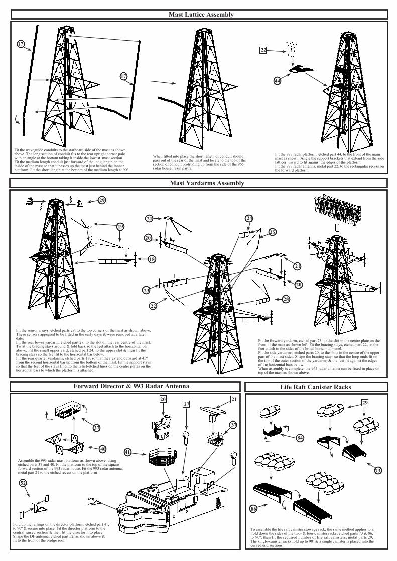
Mast Lattice Assembly
Mast Yardarms Assembly
Forward Director & 993 Radar Antenna Life Raft Canister Racks
17
1744
29
19
18
21
20
21
20
24
25
2823
22
37
40 41
52
2027
21
37
84
73
86
29
Fit the waveguide conduits to the starboard side of the mast as shownabove. The long section of conduit fits to the rear upright corner polewith an angle at the bottom taking it inside the lowest mast section.Fit the medium length conduit just forward of the long length on theinside of the mast so that it passes up the mast just behind the innnerplatform. Fit the short length at the bottom of the medium length at 90º.
When fitted into place the short length of conduit shouldpass out of the rear of the mast and locate to the top of thesection of conduit protruding up from the side of the 965radar house, resin part 2.
22
Fit the 978 radar platform, etched part 44, to the front of the mainmast as shown. Angle the support brackets that extend from the sidelattices inward to fit against the edges of the platform.Fit the 978 radar antenna, metal part 22, to the rectangular recess onthe forward platform.
Fit the sensor arrays, etched parts 29, to the top corners of the mast as shown above.These sensors appeared to be fitted in the early days & were removed at a laterdate.Fit the rear lower yardarm, etched part 28, to the slot on the rear centre of the mast.Twist the bracing stays around & fold back so the feet attach to the horizontal barabove. Fit the small upper yard, etched part 24, to the upper slot & then fit thebracing stays so the feet fit to the horizontal bar below.Fit the rear quarter yardarms, etched parts 18, so that they extend outward at 45ºfrom the second horizontal bar up from the bottom of the mast. Fit the support staysso that the feet of the stays fit onto the relief-etched lines on the centre plates on thehorizontal bars to which the platform is attached.
Fit the forward yardarm, etched part 23, to the slot in the centre plate on thefront of the mast as shown left. Fit the bracing stays, etched part 22, so the feet attach to the sides of the broad horizontal panel.Fit the side yardarms, etched parts 20, to the slots in the centre of the upperpart of the mast sides. Shape the bracing stays so that the loop ends fit onthe top of the outer section of the yardarms & the feet fit against the edgesof the horizontal bars below.When assembly is complete, the 965 radar antenna can be fixed in place ontop of the mast as shown above.
Assemble the 993 radar mast platform as shown above, using etched parts 37 and 40. Fit the platform to the top of the squareforward section of the 993 radar house. Fit the 993 radar antenna,metal part 21 to the etched recess on the platform
Fold up the railings on the director platform, etched part 41,to 90º & secure into place. Fit the director platform to thecentral raised section & then fit the director into place.Shape the DF antenna, etched part 52, as shown above &fit to the front of the bridge roof.
To assemble the life raft canister stowage rack, the same method applies to all.Fold down the sides of the two- & four-canister racks, etched parts 73 & 86,to 90º, then fit the required number of life raft canisters, metal parts 29.The single-canister racks fold up to 90º & a single canister is placed into thecurved end sections.

Foc’sle Fittings Assembly Upper Superstructure Railings
Forward Superstructure Railings & Fittings Location
Aft Superstructure Deck & Funnel Fittings
7
76
75
7
25
15
15
15
88
88
1614
4
12
12
2
90
90
42
92
56
56
26
9
17
917
10
8
10
310
87
If the jack staff is to be fitted to the bow, assemble as shownusing etched parts 75 & 76. The ensign staff on the stern isassembled in the same way.
Gently curve the railings, etched parts 7, & fit tothe edges of the foc’sle deck. The cropped sectionsof railing at the front can be joined together or madeto meet up with the jackstaff.
Shape & fit the railings sections 14 & 16 to the tops of the 965 & 993 radar housesrespectively.Fit the forward sections of railings, etched parts 15, to each side of the signal deck, anglingthe end sections outward along the edges of the ladder landings. Shape & fit the inclinedladders, etched parts 88, to the ladder landings with the uprights attaching to the railings.
Shape & fit the railings sections, etched parts 4, to the edges of the forward superstructure deckas shown left. Allow a gap for the vertical ladder access.Shape & fit railings, etched parts 2, to the edges of the Sea Cat deck on the superstructure.Note that the small end section is angled to fit onto the forward part of the boat deck.Shape & fit the railings sections, etched parts 12, to the edges of the deck adjacent to thechaff launcher enclosures. Small inclined ladders, etched parts 90, run down from the chafflauncher deck to the Sea Cat deck.
Fold the whip aerial bases, etched parts 42, in half, trapping a length of wireor stretched sprue in the top etched recess to make the whip aerial. Fit theaerials to the deck forward of the bridge as shown.Fit the assembled 20mm Oerlikons to the tops of the pintles facing forwardor outboard as desired.Shape & fit the small inclined ladders and landings, etched parts 56, to thebulwarks on the front of the bridge wings as shown right.Fit the chaff launcher enclosures to each side of the bridge deck as shown,then fit the Corvus chaff launchers into place inside. Note: Allow enoughroom between the front of the chaff launcher enclosure & the edge of thedeck to fit the railing sections.Fit the large VHF whip aerial bases, metal parts 17, to the locating holes atthe forward end of the Sea Cat deck.Fit the Sea Cat launchers, metal parts 26, into the locating holes at the aftend of the Sea Cat deck.
Shape & fit the railing sections, etched parts 8, to the forward edges of the Sea Cat director deck.Allow a small gap to fit the short steps, etched parts 38.Shape & fit the boat deck railings, etched parts 10, to the edges of the boat decks on each side.Shape & fit the small railings sections around the tops of the ladderways.
Shape &d fit the inclined ladders, etched parts 87, to run from the boat deck to the main deck.Fit the Sea Cat directors, resin parts 10, to the locating holes on the director deck. Fit the quadlife raft racks to the extended strip of deck aft of the boat deck.

Fold the sides of the fuel can rack round to 90º so that they are parallel,then fold the top & front panels down in stages of 90º so that they forma box construction rack.These racks are meant to contain the Jerry cans of fuel required by theship's boats.They have a quick overboard release capability due to theflammable contents, & are painted red.
Aft Superstructure Railings Location Aft Funnel Fittings Assembly
FDO’s Catwalk Location
Mortar Well Railings Location Flight Deck & Mortar Well Fittings
78
77
8
8
9
8
78
78
17
89
89
54
5455
83
67
69
8239
69
5
11
11
27
12
14
14
71
70
68
53
71
68
Shape & fit the railings sections, etched parts 8, to the aftedges of the director deck as show below. The small sectionsof railing fit to the inboard edges of the ladder landings. Thesingle length of railing fits along the back of the FDO's position.Shape the inclined ladders, etched parts 89, & fit to theaft edges of the landings on each side of the FDO's position.Fit the fuel can racks to the rear outer edges of the directorplatforms.Fit the remaining two large whip aerial bases, metal parts 17,to the locating holes at the forward ends of the boat decks.
Gently curve the rear funnel vent grille, etched part 83, to fit the curve of the funnel ata point 1.5mm down from the edge of the funnel cap.Fold the floodlight support frames, etched parts 54, along the vertical post until theyare angled inward. Fit to the funnel so that the inner vertical post on the floodlightframe fits just outboard of the funnel vent grille. Fit the vertical post on the supportframe to the funnel so that floodlight frames are in line with each other athwartships.Fit the floodlights, etched parts 55, to the circular backs fitted in the floodlight frame.Shape and fit the wire antenna masts, etched parts 67 and 69 to the front of the funnelcap as shown above.
Fold the railings on etched part 39 up to 90º so that they are parallel. Fit thecatwalk so that it bridges the gap between the mortar handling room roof &the walkway around the FDO's position. Shape and fit the aft RAS sheerlegs,etched part 82, to the bulkhead on the FDO's position as shown.
Shape & fit the railings section, etched part 5, around the mortar well, which involves fitting italong the edges of the flight deck catwalk, the inner edge of the mortar handling room roof, &the inner edge of the air office roof.Shape & fit the railings sections, etched parts 11P, to the outer edges of the air office roof.There are alternative fittings for the starboard railing section, etched part 11S.The first is a straightforward fit of the shorter length, folded to 90º & fitted to the forward endof the mortar handling room roof. This applies in both cases. Cut the two sections from the endof the longer railing 11S &d shape them to fit the angled catwalk extension below the flight deckas shown above.The alternative is to remove the solid bulwark from the deck edge & replace that with the wholeof the longer section of 11S.
Fit the Mortar Mk10 assembly into place centrally in the mortar well. Fold the accommodation ladder davits,etched parts 53, in half so that they are double-thickness. Fit these to the outside walls of the mortar handlingroom & the air office at the forward ends.The hangar roof covers, resin parts 14, can be fitted in one piece as the helicopter would be stowed below inthe hangar. This involves fixing the cover section down to the flight deck so that it covers the engraved linesof the elevator.If the helicopter is to be ranged on deck, the hangar roof cover would be removed in sections & stowed onthe deck extensions on the mortar handling room roof & air office roof. To represent the stowed roof sections,cut the end two sections from one end & a single section from the other end. Fit the two sections to the stowageon the mortar handling room roof, & the single section on the air office roof.
Fit the flight deck safety nets, etched parts 70 & 71 to the rear & side edges of the flight deck. If the nets are to befitted in the raised position when the helicopter is stowed in the hangar, the side sections will need to be linkedto the rear section by cutting down the angled sections of net to fit across the gap between the sides and rear nets.If the nets are in the lowered position, the angled sections, parts 68, will fit across the corners of the flight deck &dlink up the side & rear sections.

Variable Depth Sonar (VDS) Pit Head Gear Assembly (Ashanti & Gurkha Only) VDS Body and Cradle AssemblyFold the lower sections of the pit head wheel, etched part60, to the shape shown so that it fits over the VDS body.Laminate the two parts together so thay are double-thicknessat the top.Fold etched parts 61 to form a ‘V’ that fits against the spokesof the pit head wheel as shown below.
Fold the side frames of the support rig, etched part 58, to 90º & secure the edges of the topplate into place as shown above so that the feet of the frame are parallel. Fit the bracing frame,etched part 57, so that the long edges locate along the inside of the thicker side bars on etchedpart 58.
Fit the pit head wheel assembly so that slot in the rear fits overthe corresponding slot in the support frame top plate.
Fold up the ends of the VDS cradle, etched part 59 to 90º so that theyare parallel.Fit the VDS body into the cradle as shown.
Boat Davit assembly & Boat Location
Quarterdeck Railings & Fittings Location
46
45
45 46
7
6
2863
58
57
60
61
61
59
23
Fold the boat davit, etched parts 46, in halfso that it is double-thickness with the relief-etched detail outermost. Make four of these.
Fold up the sides of the boat davit supports, etchedparts 45, to 90º so that they are parallel. Fit therectangular base plates into the correspondingrecesses in the planked main deck as shown middleright. Fit the boat davits centrally into the supportsas shown right.
Cut the lower ends of the boat falls away from the davitsleaving them attached at the top. Pull the falls out at anangle ready to fit the boats.
Measure the distance between the davits when they are fixed into position on the deck,then mark out that distance on the boats. Drill through the boat from top to bottom witha 0.4mm drill bit making sure that the drill goes all the way through.Thread the boat falls on the davits, through the holes drilled in the boats so that they passright through. Push the boat back into the davits. The boat falls are still the correct lengthto fit back into the davits so that they can be re secured into place thus holding the boat inthe correct position.
Fit the long railings sections, etched parts 1, along the edges of themain deck from the superstructure step, aft to the stern.6
1
1
Shape the paravane crane, etched part 63, as shown below & fitto the top of the mounting pillar on the stern deck.
Fit the aft 4.5” gun mount to the locating holein the raised circle on the quarterdeck.
Fit the lug on the underside of the paravanewinch, metal part 28, into the locating hole onthe port side of the quarterdeck.
Fit the railing section, etched part 6,across the stern, between the twoupright posts of the main deck railings.

VDS Location
Wasp HAS1 Helicopter Assembly
Wasp Helicopter Colour Guide
Ships Flights Codex Numbers
427/HMS Ashanti. 442/HMS Zulu. 444/HMS Gurkha 453/HMS Eskimo457/HMS Nubian 474/HMS Mohawk 477/HMS Tartar
Humbrol 96RAF Blue Grey
Other Colours Used
Matt Black: Wheel Tyres, Undersides of Rotor Blades.Light Grey: Top Surfaces of Rotor Blades, Cockpit InteriorRed & White: Tail Rotor Blade TipsGloss Black: Tail Rotor Blades
AB
A
BA
B
C
D
EF
G
H
J
F
GG
F
D
H
E
C
J
Fold the undercarriage legs 47B in half so that they are double-thickness with the relief-etched detail outermost. Secure intoplace. Fold the ‘V’ frame on top of the undercarriage legs to90º. Make 4 of these.
Fit the lower undercarriage attachment frames to the undersideof the fuselage so that the rear of the front frame is in line withthe main door pillar, & the rear frame is in alignment with thesmall stub wings. The two parallel sections of each frame fit ontothe underside of the fuselage centrally.
Fit the front undercarriage to the fuselage so that the ends of thetop ‘V’ frame fit on to the fuselage forward with the rear foot inline with the door pillar. The point of the lower frame shouldattach to the inside of the leg just above the wheel.The rear leg top ‘V’ frame feet fit onto the outside edge of thestub wing, & again the point of the lower frame should attachto the inside of the leg just above the wheel.
Cut a groove in the top of the tail opposite to thetail rotor attachment, & fit the stabiliser wing,etched part 40J, into place.
Assemble the starboard side undercarriage legsin the same way as described for the port side.
Fold the flotation bag shells, etched parts 49F, in half so that the relief-etched detail is outermost.Fit the flotation gear attachment frames, etched parts 49G, so that the forward frames fit onto theoutside of the yoke frame between the front & rear doors. The rear frame fits with the top foot onthe front of the main rotor gearbox & the lower foot on the engine deck.The flotation bag shells then fit with the lower edges slotting into the point of the attachment framesat the thick relief-etched lines.
Fit the doublers, etched parts 49D and 49H, to the upper & lowersurfaces of the main rotor head to give the extra thickness neededfor that part. Fit the main rotor centrally to the top of the rotor shaftas shown. .
If the modeller requires the main rotor blades to be folded as forstowage, simply bend the blades rearwards at the point where thedoubler parts are fitted on the upper and lower surfaces. The twofront blades would be angled downwards slightly.
Propeller & Rudder Assembly
47
49
13
48
81
18
19
HMS Ashanti & HMS Gurkha were the only ships of the class to be fitted withVariable Depth Sonar (VDS) equipment. To convert the basic hull of the kit totake the VDS, a well must be created at the stern, offset from centre to thestaboard side. The well needs to be cut to a length of 15mm and width of 8mm.
The shallow part of the well needs to be 2mm deep, angling down at the stern to 5mm. Cuts need to be madewith a sharp craft knife at the sides & use a chisel blade to remove the material from inside the cuts. Cut tworectangular blocks of plastic from strip or sheet, to 5mm x 3mm x 2mm & fit these to the stern on each sideof the VDS well. Fit the extension plate, etched part 48 across the stern at the same level as the opening.
Cut a 10.5mm length of 30 thou (0.75mm) diameter brass rodto make the propeller shaft. Fit this into the stern gland openingas shown above, then fold the legs on etched part 18 into shape,fixing the central plate to the propeller bearing. Fit the propellerbearing onto the other end of the propeller shaft the fix the endsof the legs to the hull bottom, adjusting for height.

1 H
illvi
ew G
rove
, Eas
ingt
on, D
urha
m, S
R8
3NT
. UK
Tel
. 019
1 52
7157
4e.
mai
l: pe
ter@
atla
ntic
mod
els.
net
Web
site
http
://at
lant
icm
odel
s.ne
t
CA
TL
AN
TIC
MO
DE
LS
2015
Mai
n C
olou
r C
hart
and
Pai
ntin
g G
uide
The c
olou
r gui
de ab
ove s
how
s the
main
sche
me &
the a
reas
cove
red.
Ther
e are
small
er, le
ss ob
viou
s are
as lis
ted be
low
.
Matt
Blac
k: M
id S
ectio
n of M
ast, F
unne
l Top
Cap
s, G
un B
arre
ls. W
aterli
ne B
oot T
oppi
ng.
Matt
Whi
te: M
ast T
op A
rray,
Life
Raf
t Can
ister
Bron
ze:
P
rope
llers.
Penn
ant N
umbe
rs F
light
Dec
k C
ode
Let
ters
for
all s
hips
of t
he c
lass
R.N
.Lig
htW
eath
erw
ork
Gre
yH
umbr
ol 1
27
R.N
. Dec
k G
reen
Hum
brol
88
Ant
i Fou
ling
Red
Hum
brol
100
R.N
. Lig
htD
eck
Gre
yH
umbr
ol 1
06
HMS ASH
ANTI
F
117/
AS
HMS ESK
IMO
F119
/ES
HMS GURKHA
F
122/
GU
HMS ZU
LU
F12
4/Z
UHMS MOHAWK
F12
5/M
OHMS NUBIAN
F131
/NU
HMS TA
RTA
R
F13
3/T
A
R.N
. Lig
htD
eck
Gre
yH
umbr
ol 1
06
Dec
k O
akH
umbr
ol 7
1