type 3320, 3321,
TRANSCRIPT

Operating Instructions
Type 3320, 3321,AE3320, AE3321
Electromotive 2/2-way valve

We reserve the right to make technical changes without notice.Technische Änderungen vorbehalten.Sous réserve de modifications techniques.
© 2015 – 2018 Bürkert Werke GmbH & Co. KG
Operating Instructions 1810/03_EU-EN_00810525 / Original DE

3
Content
1 THE OPERATING INSTRUCTIONS ........................................................................................................7
1.1 Symbols ........................................................................................................................................7
1.2 Definitionsofterms ......................................................................................................................7
2 INTENDED USE ......................................................................................................................................8
3 BASIC SAFETY INSTRUCTIONS ...........................................................................................................9
4 GENERAL INFORMATION ....................................................................................................................11
4.1 Contactaddress .........................................................................................................................11
4.2 Warranty .....................................................................................................................................11
4.3 InformationontheInternet ........................................................................................................11
5 PRODUCT DESCRIPTION ....................................................................................................................12
5.1 Generaldescription ....................................................................................................................12
5.2 Properties ..................................................................................................................................12
6 STRUCTURE AND FUNCTION .............................................................................................................14
6.1 Diagram–structureoftheelectromotivevalve ........................................................................15
6.2 Valvepositionafterfailureofthesupplyvoltage......................................................................16
6.3 Safetyposition ...........................................................................................................................16
6.4 Displayofthedevicestatus ......................................................................................................17
6.5 Factorysettings.........................................................................................................................19
7 ELECTRICAL CONTROL ......................................................................................................................20
7.1 Function ......................................................................................................................................20
7.2 SAFEPOSenergy-pack(option) ................................................................................................21
8 TECHNICAL DATA ................................................................................................................................24
8.1 Conformity ..................................................................................................................................24
8.2 Standards ...................................................................................................................................24
Electromotive 2/2-way valve
Type 3320 and 3321
english
4
Type 3320 and 3321
8.3 Licenses .....................................................................................................................................24
8.4 Typelabel ...................................................................................................................................24
8.5 Operatingconditions .................................................................................................................25
8.6 Generaltechnicaldata ...............................................................................................................27
8.7 Electricaldata ............................................................................................................................27
8.8 KvvaluesforTypes3320and3321 ...........................................................................................29
9 INSTALLATION OF THE VALVE ............................................................................................................30
9.1 Safetyinstructions .....................................................................................................................30
9.2 Installationofdeviceswithsocketorflangedconnection .......................................................30
9.3 Installationofdeviceswithweldedhousing .............................................................................31
9.4 Rotatingtheactuator .................................................................................................................35
9.5 Holdingdevice ...........................................................................................................................36
10 ELECTRICAL INSTALLATION ...............................................................................................................37
10.1 Electricalinstallationwithcircularplug-inconnector .................................................................. 37
10.2 Electricalinstallationwithcablegland ......................................................................................40
11 STARTING UP .......................................................................................................................................45
11.1 Safetyinstructions .....................................................................................................................45
11.2 Basicsettings .............................................................................................................................45
11.3 Settingsafetypositionandeffectivedirection .........................................................................45
11.4 Adjustingthepositioncontrol–runningtheX.TUNE ..............................................................46
11.5 SettingAUTOMATICoperatingstate .........................................................................................48
12 OPERATION ..........................................................................................................................................49
12.1 Overview:Availabilityoftheoperatingelements......................................................................49
12.2 Displayelements ........................................................................................................................50
12.3 Operatingelements ....................................................................................................................51
12.4 büSserviceinterface .................................................................................................................52
12.5 AcceptingandsavingSIMcarddata(option) ..........................................................................53
12.6 UserinterfaceoftheBürkertCommunicatorPCsoftware ......................................................54
12.7 EstablishingaconnectionbetweenthedeviceandBürkertCommunicator ..........................55
english
5
Type 3320 and 3321
13 BASIC FUNCTIONS ..............................................................................................................................56
13.1 Switchingoperatingstate,AUTOMATIC–MANUAL ................................................................56
13.2 Settingsafetypositionandeffectivedirection .........................................................................57
14 EXTENDEDFUNCTIONS ......................................................................................................................58
14.1 X.TIME – Limitingthecontrolspeed ......................................................................................58
14.2 X.LIMIT – Limitingthemechanicalstrokerange ....................................................................59
14.3 SettingLEDmode ......................................................................................................................60
14.4 Settingthecolorsforindicatingthevalveposition ..................................................................61
15 MANUAL ACTUATION OF THE VALVE.................................................................................................62
15.1 Actuatingvalveelectrically ........................................................................................................62
15.2 Actuatingvalvemechanically ....................................................................................................63
16 OPERATING STRUCTURE / FACTORY SETTING................................................................................65
16.1 Operatingstructureoftheconfigurationarea ..........................................................................65
17 FIELDBUS GATEWAY ...........................................................................................................................72
17.1 Technicaldata ............................................................................................................................72
17.2 IndustrialEthernet ......................................................................................................................72
17.3 Electricalconnection .................................................................................................................73
17.4 AccesstothebüSserviceinterface .........................................................................................75
17.5 Webserver .................................................................................................................................75
17.6 ConfigurationandparameterizationofEtherNet/IP .................................................................79
17.7 Objectroutefunction .................................................................................................................79
17.8 Objects .......................................................................................................................................82
18 MAINTENANCE,TROUBLESHOOTING ...............................................................................................83
18.1 Safetyinstructions .....................................................................................................................83
18.2 Maintenance ...............................................................................................................................83
18.3 Troubleshooting .........................................................................................................................85
19 CLEANING ............................................................................................................................................87
english

6
Type 3320 and 3321
20 ACCESSORIES,SPAREPARTS ...........................................................................................................88
20.1 Communicationssoftware .........................................................................................................88
20.2 Spareparts .................................................................................................................................89
20.3 Installationtools .........................................................................................................................90
21 DISASSEMBLY .....................................................................................................................................91
21.1 Safetyinstructions .....................................................................................................................91
22 PACKAGING,TRANSPORT ..................................................................................................................92
23 STORAGE .............................................................................................................................................92
24 DISPOSAL ............................................................................................................................................92
english

7
The operating instructions
Type 3320 and 3321
1 THE OPERATING INSTRUCTIONSThe operating instructions describe the entire life cycle of the device. Keep these instructions in a location which is easily accessible to every user and make these instructions available to every new owner of the device.
Importantsafetyinformation.
Read the operating instructions carefully and thoroughly. Study in particular the chapters entitled Basic Safety Instructions and Intended Use.
▶ The operating instructions must be read and understood.
1.1 Symbols
DANGER!
Warnsofanimmediatedanger!
▶ Failure to observe the warning will result in fatal or serious injuries.
WARNING!
Warnsofapotentiallydangeroussituation!
▶ Failure to observe the warning may result in serious injuries or death.
CAUTION!
Warnsofapossibledanger!
▶ Failure to observe this warning may result in a moderate or minor injury.
ATTENTION!
Warnsofdamagetoproperty.
• Failure to observe the warning may result in damage to the device or other equipment.
Indicates important additional information, tips and recommendations.
Refers to information in these operating instructions or in other documentation.
▶ designates instructions for risk prevention.
→ designates a procedure which you must carry out.
indicates a result.
1.2 Definitions of terms
• The term "device" used in these instructions applies to all valve types described in these instructions: Type 3320, electromotive 2/2-way angle seat valve Type 3321, electromotive 2/2-way globe valve
• In these instructions, the abbreviation "Ex" stands for "explosion-risk".
english
8
Intended use
Type 3320 and 3321
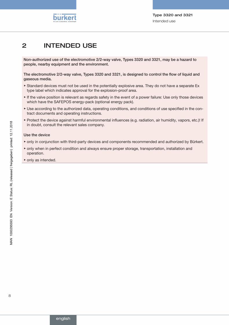
2 INTENDED USE
Non-authorizeduseoftheelectromotive2/2-wayvalve,Types3320and3321,maybeahazardtopeople,nearbyequipmentandtheenvironment.
Theelectromotive2/2-wayvalve,Types 3320and3321,isdesignedtocontroltheflowofliquidandgaseousmedia.
▶ Standard devices must not be used in the potentially explosive area. They do not have a separate Ex type label which indicates approval for the explosion-proof area.
▶ If the valve position is relevant as regards safety in the event of a power failure: Use only those devices which have the SAFEPOS energy-pack (optional energy pack).
▶ Use according to the authorized data, operating conditions, and conditions of use specified in the con-tract documents and operating instructions.
▶ Protect the device against harmful environmental influences (e.g. radiation, air humidity, vapors, etc.)! If in doubt, consult the relevant sales company.
Usethedevice
▶ only in conjunction with third-party devices and components recommended and authorized by Bürkert.
▶ only when in perfect condition and always ensure proper storage, transportation, installation and operation.
▶ only as intended.
english
9
Basic safety instructions
Type 3320 and 3321
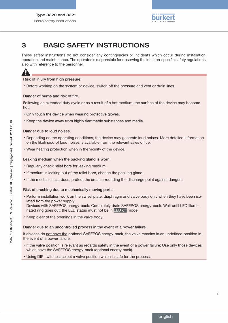
3 BASIC SAFETY INSTRUCTIONSThese safety instructions do not consider any contingencies or incidents which occur during installation, operation and maintenance. The operator is responsible for observing the location-specific safety regulations, also with reference to the personnel.
Riskofinjuryfromhighpressure!
▶ Before working on the system or device, switch off the pressure and vent or drain lines.
Dangerofburnsandriskoffire.
Following an extended duty cycle or as a result of a hot medium, the surface of the device may become hot.
▶ Only touch the device when wearing protective gloves.
▶ Keep the device away from highly flammable substances and media.
Dangerduetoloudnoises.
▶ Depending on the operating conditions, the device may generate loud noises. More detailed information on the likelihood of loud noises is available from the relevant sales office.
▶ Wear hearing protection when in the vicinity of the device.
Leakingmediumwhenthepackingglandisworn.
▶ Regularly check relief bore for leaking medium.
▶ If medium is leaking out of the relief bore, change the packing gland.
▶ If the media is hazardous, protect the area surrounding the discharge point against dangers.
Riskofcrushingduetomechanicallymovingparts.
▶ Perform installation work on the swivel plate, diaphragm and valve body only when they have been iso-lated from the power supply. Devices with SAFEPOS energy-pack: Completely drain SAFEPOS energy-pack. Wait until LED illumi-nated ring goes out; the LED status must not be in LEDoff mode.
▶ Keep clear of the openings in the valve body.
Dangerduetoanuncontrolledprocessintheeventofapowerfailure.
If devices do not have the optional SAFEPOS energy-pack, the valve remains in an undefined position in the event of a power failure.
▶ If the valve position is relevant as regards safety in the event of a power failure: Use only those devices which have the SAFEPOS energy-pack (optional energy pack).
▶ Using DIP switches, select a valve position which is safe for the process.
english
10
Basic safety instructions
Type 3320 and 3321
Generalhazardoussituations.
To prevent injuries:
▶ In a hazardous area, the device may be used only in accordance with the specification on the separate Ex type label.
▶ To use the device in an explosion-risk area, observe the additional information with safety instruc-tions for the explosion-risk area enclosed with the device or the separate explosion-risk operating instructions.
▶ Devices without a separate Ex type label may not be used in a potentially explosive area.
▶ Only feed in the media types specified in chapter "8 Technical data" to the media connections.
▶ Do not make any internal or external changes on the device and do not subject it to mechanical stress.
▶ Transport, install and dismantle a heavy device with the help of another person and with appropriate tools.
▶ Secure the system from unintentional actuation.
▶ Only trained technicians may perform installation and maintenance work.
▶ After an interruption, ensure that the process is restarted in a controlled manner. Observe sequence. 1. Apply supply voltage. 2. Charge the device with medium.
▶ Observe the general rules of technology.
▶ The valves must be installed in accordance with the regulations applicable in the country.
ATTENTION!Electrostaticsensitivecomponentsandmodules.
The device contains electronic components which react sensitively to electrostatic discharge (ESD). Contact with electrostatically charged persons or objects are hazardous to these components. In the worst case scenario, they will be destroyed immediately or will fail after starting up.
• Observe the requirements in accordance with EN 61340-5-1 to minimize or avoid the possibility of damage caused by sudden electrostatic discharge!
• Do not touch electronic components while the supply voltage is switched on!
english
11
General information
Type 3320 and 3321
4 GENERAL INFORMATION
4.1 Contact address
Germany
Bürkert Fluid Control Systems Sales Center Christian-Bürkert-Str. 13-17 D-74653 Ingelfingen Germany Tel. + 49 (0) 7940 - 10 91 111 Fax + 49 (0) 7940 - 10 91 448 Email: [email protected]
International
Contact addresses can be found on the final pages of the printed operating instructions.
And also on the Internet at:
www.burkert.com
4.2 Warranty
The warranty is only valid if the device is used as intended in accordance with the specified application conditions.
4.3 Information on the Internet
Operating instructions and data sheets for Types 3320 and 3321 can be found on the Internet at:
www.buerkert.com
english
12
Product description
Type 3320 and 3321
5 PRODUCT DESCRIPTION
5.1 General description
The electromotive 2/2-way valve Type 3320 and 3321 is suitable for liquid and gaseous media.
This may be neutral gas, water, alcohol, oil, propellant, hydraulic fluid, saline solution, alkali, organic solvent and vapor.
The 2/2-way valve has an electromotive linear actuator with the electronic control system which is actuated either via binary signals or via a fieldbus (digital). The electromotive linear actuator has been designed in such a way that it has an optimum degree of efficiency. At the same time the actuator keeps the valve tight in a de-energized state even at the maximum specified medium pressure.
Optionally there is the energy pack (SAFEPOS energy-pack) for the device. If the supply voltage fails, the energy pack supplies the actuator with the required energy to move the valves into the required position which can be adjusted in the menu.
The valve position can be manually changed in 2 ways. 1. Electrical manual control: is used when supply voltage applied. 2. Mechanical manual control: may only be used if no supply voltage applied.
The device can be operated with 2 capacitive buttons and 4 DIP switches. There is also the option of setting the device via the büS service interface and by using the PC software "Bürkert Communicator". To make the setting using the "Bürkert Communicator", the USB büS interface set, available as an accessory, is required.
5.2 Properties
• High leak-tightness by self-adjusting packing gland.
• Devices with PTFE and PEEK seal material are kept tight without the power supply.
• High flow values by the streamlined valve body made of stainless steel.
• Mechanical position indicator which shows the valve position even if the supply voltage fails.
• 360° LED illuminated ring for displaying the device statuses, valve end positions and operating state.
• To keep the valve position, no electrical energy is required even at maximum medium pressure, except for the basic consumption for actuation.
• Simple and fast replacement of the pendulum disk.
• Valve actuator can be rotated through 360°.
• Integrated control.
• High seat tightness by pendulum disk.
• Non-contact, high-resolution and wear-free position sensor.
• The actuator housing consists of a robust and heat-dissipating aluminum body. The coating is resistant to the usual cleaning agents. The plastic materials used for the actuator housing are also resistant to cleaning agents.
english
13
Product description
Type 3320 and 3321
5.2.1 Versions (valve sizes and actuator sizes)
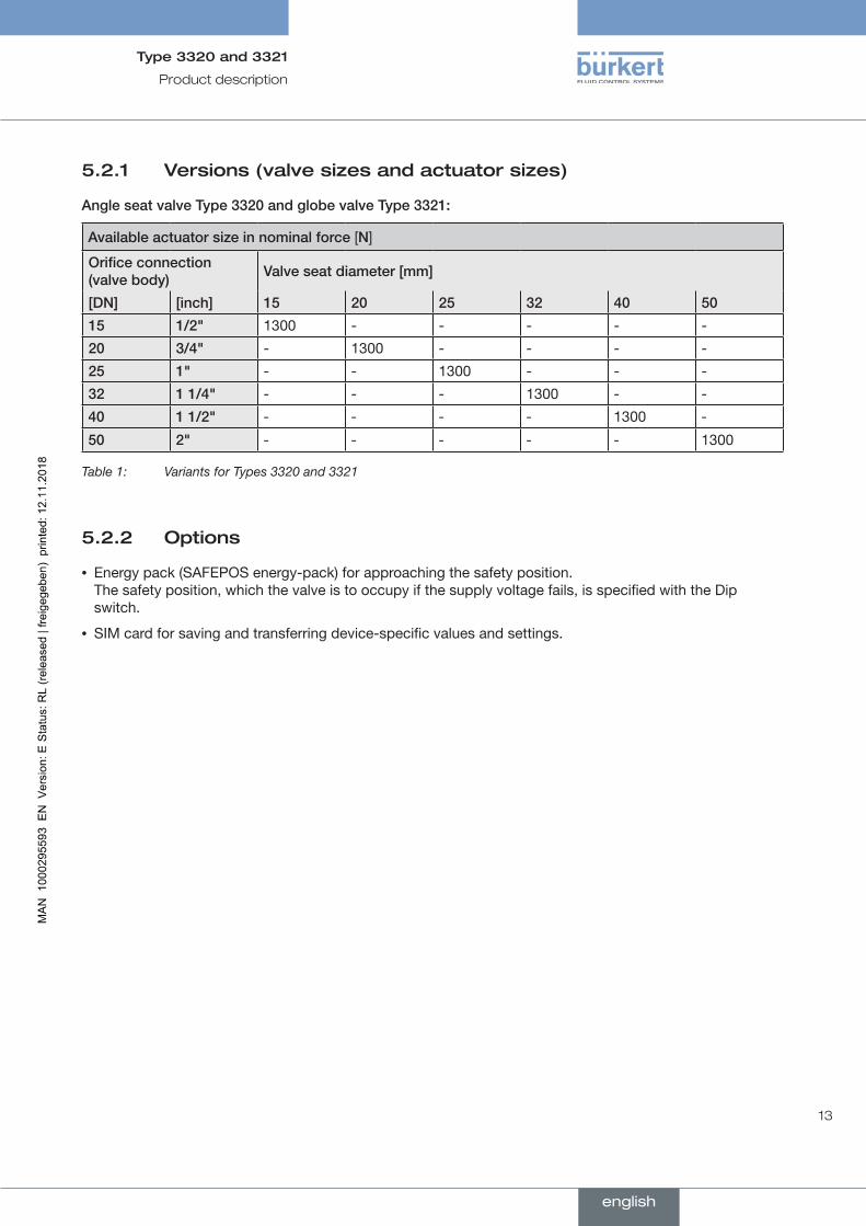
AngleseatvalveType3320andglobevalveType3321:
Availableactuatorsizeinnominalforce[N]
Orificeconnection(valvebody) Valveseatdiameter[mm]
[DN] [inch] 15 20 25 32 40 50
15 1/2" 1300 - - - - -
20 3/4" - 1300 - - - -
25 1" - - 1300 - - -
32 1 1/4" - - - 1300 - -
40 1 1/2" - - - - 1300 -
50 2" - - - - - 1300
Table 1: Variants for Types 3320 and 3321
5.2.2 Options
• Energy pack (SAFEPOS energy-pack) for approaching the safety position. The safety position, which the valve is to occupy if the supply voltage fails, is specified with the Dip switch.
• SIM card for saving and transferring device-specific values and settings.
english
14
Structure and function
Type 3320 and 3321
6 STRUCTURE AND FUNCTIONThe electromotive valve consists of an electromotively driven linear actuator, a swivel plate and a 2/2-way straight seat valve body or a 2/2-way angle seat valve body.
The electronic control and the "SAFEPOS energy-pack" are housed in the side of the linear actuator.
The electronic control consists of the microprocessor-controlled electronics and the position sensor.
Control is via binary signals (analog) or via fieldbus (digital).
The electromotive control valve is designed using three-wire technology. The valve is operated using 2 buttons and 4 DIP switches.
The electromotive linear actuator consists of a brushless direct current motor, gears and a threaded spindle. The valve spindle, which is connected to the threaded spindle, transfers the force to the pendulum disk.
• The linear actuator is designed in such a way that it does not require electrical energy to keep the valve position, i.e. when it is at a standstill, only the electronic control consumes energy.
• The flow-enhancing valve body made of stainless steel enables high flow values.
• The self-adjusting packing gland ensures high leak-tightness. The pendulum disk is coupled to the actuator spindle with a bolt and can therefore be quickly replaced.
• The actuator housing consists of a robust and heat-dissipating aluminum body which has a coating resistant to cleaning agents. The plastic materials used are also resistant to cleaning agents.
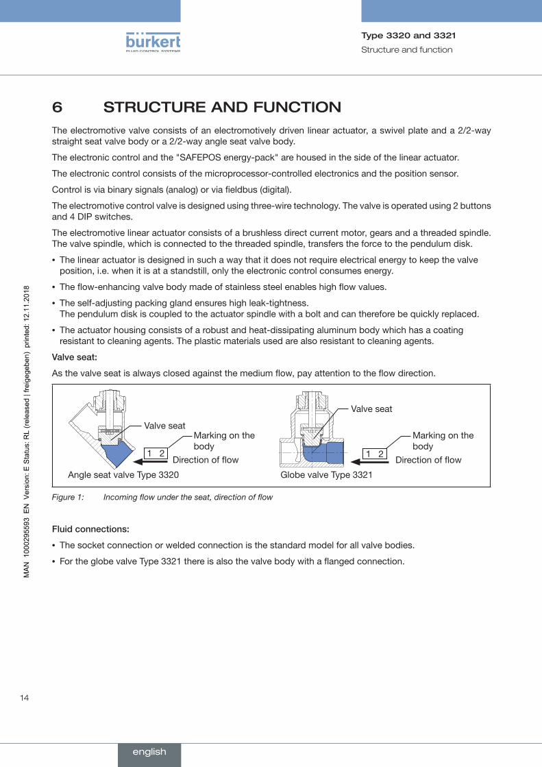
Valveseat:
As the valve seat is always closed against the medium flow, pay attention to the flow direction.
Globe valve Type 3321 Angle seat valve Type 3320
Direction of flow
Valve seat
Valve seat
Direction of flow1 2
Marking on the body
1 2
Marking on the body
Figure 1: Incoming flow under the seat, direction of flow
Fluidconnections:
• The socket connection or welded connection is the standard model for all valve bodies.
• For the globe valve Type 3321 there is also the valve body with a flanged connection.
english
15
Structure and function
Type 3320 and 3321
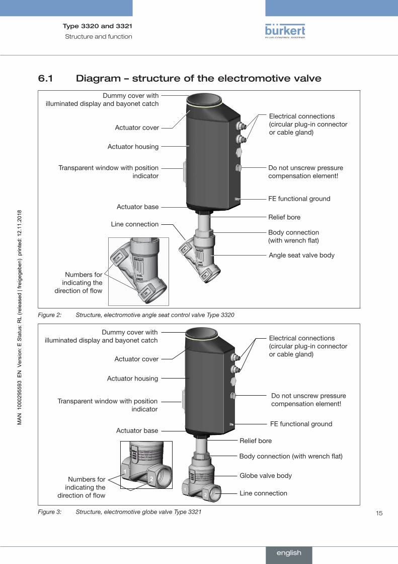
6.1 Diagram – structure of the electromotive valve
Dummy cover with illuminated display and bayonet catch
Actuator housing
Actuator cover
Transparent window with position indicator
Electrical connections (circular plug-in connector or cable gland)
Body connection (with wrench flat)
Line connection
Angle seat valve body
Actuator baseFE functional ground
Relief bore
Do not unscrew pressure compensation element!
Numbers for indicating the
direction of flow
Figure 2: Structure, electromotive angle seat control valve Type 3320
Do not unscrew pressure compensation element!
Dummy cover with illuminated display and bayonet catch
Actuator housing
Actuator cover
Transparent window with position indicator
Electrical connections (circular plug-in connector or cable gland)
Body connection (with wrench flat)
Numbers for indicating the
direction of flow Line connection
Globe valve body
Actuator baseRelief bore
FE functional ground
Figure 3: Structure, electromotive globe valve Type 3321
english
16
Structure and function
Type 3320 and 3321
6.2 Valve position after failure of the supply voltage
If the electromotive actuator is at a standstill due to failure of the supply voltage, the valve remains in the last occupied position.
If the supply voltage fails while the actuator is changing the valve position, the valve stops in an undefined position. The actuator flywheel mass and the medium pressure continue to affect the valve spindle until it finally comes to a standstill.
Description of the SAFEPOS energy-pack see chapter "7.2 SAFEPOS energy-pack (option)" on page 21
6.3 Safety position
The DIP switch defines the safety position which the valve occupies in the following cases:
• Internal error
• Failure of the supply voltage (optional) This function is available only on devices which have the optionally available SAFEPOS energy-pack.
ThefollowingsafetypositionsareselectedforSAFEPOS:
• Close = Valve closed
• Open = Valve open
• Inactive = Valve stops in an undefined position if the supply voltage fails.
english
17
Structure and function
Type 3320 and 3321
6.4 Display of the device status
The device status is indicated at the LED illuminated ring. To indicate the device status and the valve position, differentLED modes can be set:
• Valve mode
• Valve mode + warnings (mode set in the factory)
• NAMUR mode
* The description for setting the LED mode can be found in chapter "14.3 Setting LED mode" on page 60.
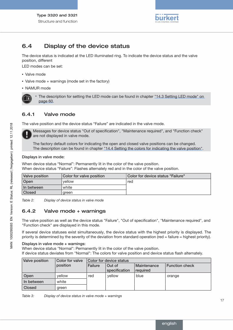
6.4.1 Valve mode
The valve position and the device status “Failure” are indicated in the valve mode.
Messages for device status "Out of specification", "Maintenance required", and "Function check" are not displayed in valve mode.
The factory default colors for indicating the open and closed valve positions can be changed. The description can be found in chapter "14.4 Setting the colors for indicating the valve position".
Displaysinvalvemode:
When device status “Normal”: Permanently lit in the color of the valve position. When device status “Failure”: Flashes alternately red and in the color of the valve position.
Valveposition Colorforvalveposition Colorfordevicestatus"Failure"Open yellow redInbetween whiteClosed green
Table 2: Display of device status in valve mode
6.4.2 Valve mode + warnings
The valve position as well as the device status "Failure", "Out of specification", "Maintenance required", and "Function check" are displayed in this mode.
If several device statuses exist simultaneously, the device status with the highest priority is displayed. The priority is determined by the severity of the deviation from standard operation (red = failure = highest priority).
Displaysinvalvemode+warnings: When device status "Normal": Permanently lit in the color of the valve position. If device status deviates from "Normal": The colors for valve position and device status flash alternately.
Valveposition Colorforvalveposition
ColorfordevicestatusFailure Outof
specificationMaintenancerequired
Functioncheck
Open yellow red yellow blue orangeInbetween whiteClosed green
Table 3: Display of device status in valve mode + warnings
english
18
Structure and function
Type 3320 and 3321
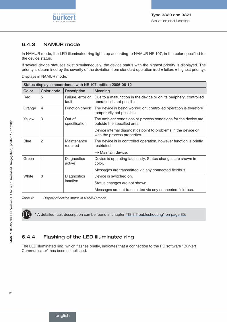
6.4.3 NAMUR mode
In NAMUR mode, the LED illuminated ring lights up according to NAMUR NE 107, in the color specified for the device status.
If several device statuses exist simultaneously, the device status with the highest priority is displayed. The priority is determined by the severity of the deviation from standard operation (red = failure = highest priority).
Displays in NAMUR mode:
StatusdisplayinaccordancewithNE107,edition2006-06-12
Color Colorcode Description Meaning
Red 5 Failure, error or fault
Due to a malfunction in the device or on its periphery, controlled operation is not possible
Orange 4 Function check The device is being worked on; controlled operation is therefore temporarily not possible.
Yellow 3 Out of specification
The ambient conditions or process conditions for the device are outside the specified area.
Device internal diagnostics point to problems in the device or with the process properties.
Blue 2 Maintenance required
The device is in controlled operation, however function is briefly restricted.
→Maintain device.
Green 1 Diagnostics active
Device is operating faultlessly. Status changes are shown in color.
Messages are transmitted via any connected fieldbus.
White 0 Diagnostics inactive
Device is switched on.
Status changes are not shown.
Messages are not transmitted via any connected field bus.
Table 4: Display of device status in NAMUR mode
* A detailed fault description can be found in chapter "18.3 Troubleshooting" on page 85.
6.4.4 Flashing of the LED illuminated ring
The LED illuminated ring, which flashes briefly, indicates that a connection to the PC software "Bürkert Communicator" has been established.
english
19
Structure and function
Type 3320 and 3321
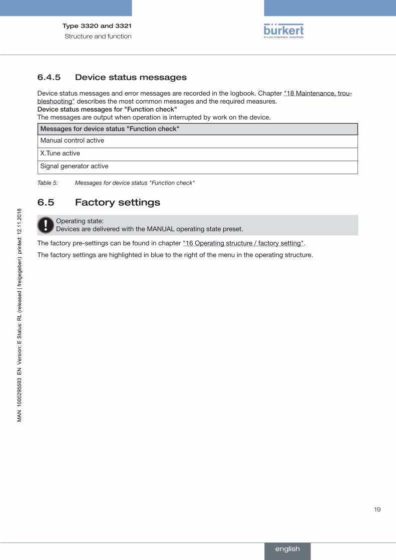
6.4.5 Device status messages
Device status messages and error messages are recorded in the logbook. Chapter "18 Maintenance, trou-bleshooting" describes the most common messages and the required measures.Devicestatusmessagesfor"Functioncheck" The messages are output when operation is interrupted by work on the device.
Messagesfordevicestatus"Functioncheck"
Manual control active
X.Tune active
Signal generator active
Table 5: Messages for device status "Function check"
6.5 Factory settings
Operating state: Devices are delivered with the MANUAL operating state preset.
The factory pre-settings can be found in chapter "16 Operating structure / factory setting".
The factory settings are highlighted in blue to the right of the menu in the operating structure.
english
20
Electrical control
Type 3320 and 3321
7 ELECTRICAL CONTROL
7.1 Function
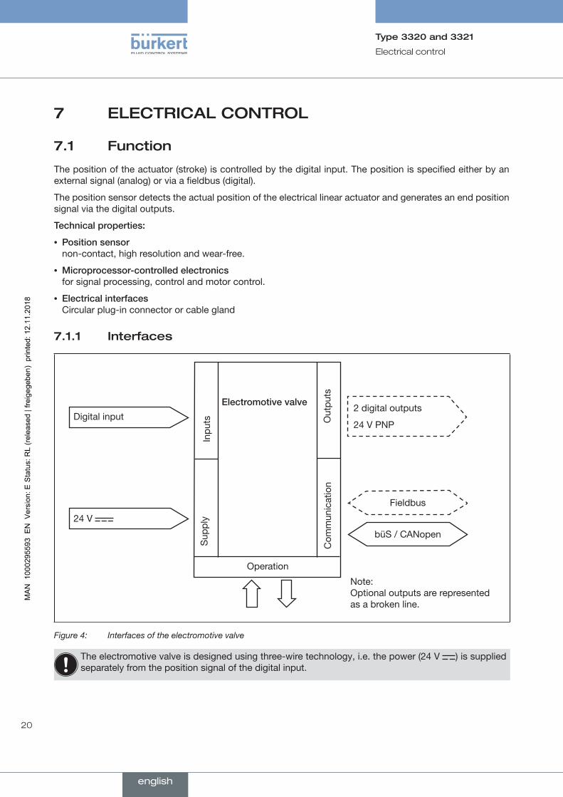
The position of the actuator (stroke) is controlled by the digital input. The position is specified either by an external signal (analog) or via a fieldbus (digital).
The position sensor detects the actual position of the electrical linear actuator and generates an end position signal via the digital outputs.
Technicalproperties:
• Positionsensor non-contact, high resolution and wear-free.
• Microprocessor-controlledelectronics for signal processing, control and motor control.
• Electricalinterfaces Circular plug-in connector or cable gland
7.1.1 Interfaces
Digital input
24 V
Electromotivevalve2 digital outputs
24 V PNP
Inpu
ts Out
puts
Sup
ply
Operation
Note: Optional outputs are represented as a broken line.
Com
mun
icat
ion
Fieldbus
büS / CANopen
Figure 4: Interfaces of the electromotive valve
The electromotive valve is designed using three-wire technology, i.e. the power (24 V ) is supplied separately from the position signal of the digital input.
english
21
Electrical control
Type 3320 and 3321
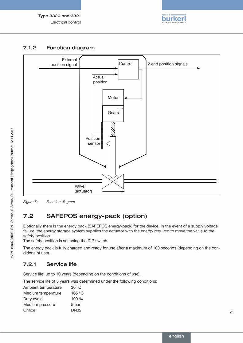
7.1.2 Function diagram
Control
Actual position
External position signal
Valve (actuator)
Gears
Motor
Position sensor
2 end position signals
Figure 5: Function diagram
7.2 SAFEPOS energy-pack (option)
Optionally there is the energy pack (SAFEPOS energy-pack) for the device. In the event of a supply voltage failure, the energy storage system supplies the actuator with the energy required to move the valve to the safety position. The safety position is set using the DIP switch.
The energy pack is fully charged and ready for use after a maximum of 100 seconds (depending on the con-ditions of use).
7.2.1 Service life
Service life: up to 10 years (depending on the conditions of use).
The service life of 5 years was determined under the following conditions: Ambient temperature 30 °CMedium temperature 165 °CDuty cycle 100 %Medium pressure 5 barOrifice DN32
english

22
Electrical control
Type 3320 and 3321
ATTENTION!The SAFEPOS energy-pack is a wearing part. Information on the service life are guide values which are not guaranteed.
7.2.2 Messages on the state of the SAFEPOS energy-pack
Thedeviceissuesamaintenancemessage: The remaining service life of the energy storage is approx. 25 %! The energy storage must be changed soon.
Replace SAFEPOS energy-pack in good time before the service life ends.
Thedeviceissuesanerrormessageandmovestothesafetyposition: The SAFEPOS energy-pack was not replaced in good time after the warning was issued. The storage capacity is so low that there is no guarantee that the safety position can be approached.
7.2.3 Replacing SAFEPOS energy-pack
CAUTION!
Riskofinjuryduetoelectricshock.
▶ Before removing the SAFEPOS energy-pack, switch off the supply voltage.
▶ Completely drain SAFEPOS energy-pack. Wait until LED illuminated ring goes out; the LED status must not be in LEDoff mode, see chapter "14.3 Setting LED mode".
The SAFEPOS energy-pack is housed in the actuator housing. To replace it, remove the following parts from the actuator:
DeviceswithATEXapprovalorIECExapprovalaresecuredwithamagneticlock.
The removal of the cover is described in the additional manual for electromotive control valves with ATEX approval and IECEx approval.
1. Dummy cover
2. LED and storage module
3. Actuator cover
The removal of these parts is described in detail in chapter "10.2.2 Access to the connection terminals" on page 40.
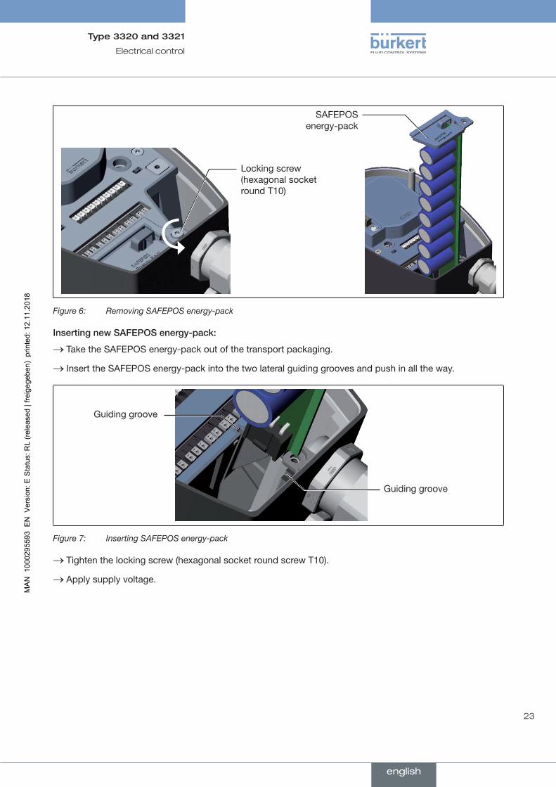
RemovingSAFEPOSenergy-pack:
→ Loosen the locking screw (hexagonal socket round screw T10).
→ Completely pull out the SAFEPOS energy-pack on the bracket.
english
23
Electrical control
Type 3320 and 3321
Locking screw (hexagonal socket round T10)
SAFEPOS energy-pack
Figure 6: Removing SAFEPOS energy-pack
InsertingnewSAFEPOSenergy-pack:
→ Take the SAFEPOS energy-pack out of the transport packaging.
→ Insert the SAFEPOS energy-pack into the two lateral guiding grooves and push in all the way.
Guiding groove
Guiding groove
Figure 7: Inserting SAFEPOS energy-pack
→ Tighten the locking screw (hexagonal socket round screw T10).
→ Apply supply voltage.
english
24
Technical data
Type 3320 and 3321
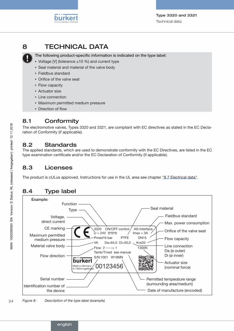
8 TECHNICAL DATAThefollowingproduct-specificinformationisindicatedonthetypelabel:
• Voltage [V] (tolerance ±10 %) and current type • Seal material and material of the valve body • Fieldbus standard • Orifice of the valve seat • Flow capacity • Actuator size • Line connection • Maximum permitted medium pressure • Direction of flow
8.1 ConformityThe electromotive valves, Types 3320 and 3321, are compliant with EC directives as stated in the EC Decla-ration of Conformity (if applicable).
8.2 StandardsThe applied standards, which are used to demonstrate conformity with the EC Directives, are listed in the EC type examination certificate and/or the EC Declaration of Conformity (if applicable).
8.3 Licenses
The product is cULus approved. Instructions for use in the UL area see chapter "8.7 Electrical data".
8.4 Type label
3320 ON/OFF-control AS-Interface
Pmed16 bar PTFE DN15VA Da=64,0 Di=50,0 Kvs20
Flow 2 -----> 1 1300NTamb/Tmed see manualS/N:1001 W19MN
00123456Made in Germany D-74653 Ingelfingen
U = 24V Imax = 3A
Voltage, direct current Max. power consumption
Orifice of the valve seat
Flow capacity
Actuator size (nominal force)
Line connection Da (ø outer) Di (ø inner)
Date of manufacture (encoded)Identification number of
the device
FunctionType
Maximum permitted medium pressure
Material valve body
CE marking
Flow direction
Permitted temperature range (surrounding area/medium)
Serial number
Seal material
Fieldbus standard
Example:
Figure 8: Description of the type label (example)
english

25
Technical data
Type 3320 and 3321
8.4.1 Additional type label for UL approval (example)
Type AE3320
Power Supply
SELV / PELV only!LISTEDProcess Control Equipment
E238179
Figure 9: Additional type label for UL approval (example)
8.5 Operating conditions
Foroperationofthedeviceobservetheproduct-specificinformationonthetypelabel.
WARNING!
Malfunctionifthetemperatureexceedsordropsbelowthepermittedtemperaturerange.
▶ Never expose the device outdoors to direct sunlight.
▶ The temperature must not exceed or drop below the permitted ambient temperature range.
WARNING!
Reducedsealingfunctionifmediumpressuretoohigh.
As the valve seat is closed against the medium flow, the medium pressure may become too high and prevent the valve seat from closing tightly.
▶ The medium pressure must not be greater than the maximum value specified on the type label.
Maximum permitted medium pressure: see type label
Media: Neutral gases and vapor. Liquid media: Water, alcohol, oil, propellant, hydraulic fluid, saline solution, alkali, organic solvent.
Degree of protection: (verified by Bürkert / not evaluated by UL) IP65 as per IEC 529, EN 60529 (IP67 on request). NEMA 250 4x (not guaranteed for installation location: actuator facing downward).
Direction of flow: is specified on the rating plate by an arrow and the numbers 1 and 2. The 1 and the 2 stand for identification also on the valve body. The incoming flow is under the seat.
Altitude: up to 2000m above sea level
english

26
Technical data
Type 3320 and 3321
8.5.1 Permitted temperature ranges
Minimum temperatures Ambient: -25 °C (-13 °F) Medium: -10 °C (14°F)
Maximum temperatures Ambient: depending on the medium temperature; see temperature graph below.
Medium: depending on the ambient temperature; see temperature graph below. On devices with seat seal PTFE/steel, max. +130 °C (266 °F) absolute. On devices with seat seal PEEK/steel, max. + 185 °C (365 °F) absolute.
Temperaturegraph
The maximum permitted temperature for the environment and the medium depend on each other. The permitted maximum temperatures of the device versions can be determined from the characteristics of the temperature graph. The values were determined under the following maximum operating conditions: Orifice DN32 when 100% duty cycle at 16 bar medium pressure.
For deviating operating conditions an individual verification can be performed. Please contact your Bürkert office for more information.
0 20 60 100 140 180 20040 80 120 160
Mediumtemperature[°C]
Ambienttemperature[°C]
70
60
50
40
30
20
10
0
Devices without SAFEPOS energy-packDevices with SAFEPOS energy-pack* or fieldbus gateway
Figure 10: Temperature graph
* The service life of the SAFEPOS energy-pack depends on the medium temperature and the ambient temperature. For description see "7.2 SAFEPOS energy-pack (option)"
english
27
Technical data
Type 3320 and 3321
8.6 General technical data
Dimensions: See data sheet
Weight: See data sheet
Materials Actuator: PPS and aluminum powder-coated Valve body: 316L Body connection: 316L / 1.4401 Spindle: 1.4401 / 1.4404 Spindle guide: PEEK Packing gland PTFE V-rings with spring
compensation (carbon-filled PTFE)
Seal material Sealing element actuator housing: EPDM Valve seat seal: See type label
Fluid connection Possible connection types: Socket connection G ½...G 2 (NPT, RC on request)
Welded connection according to EN ISO 1127 (ISO 4200), DIN 11850 Series 2
Also for globe valves of Type 3321: Flanged connection in accordance with DIN 2634, ANSI B16.5 class 150, JIS 10K
Other connections on request
Electrical connection: By connection terminals or circular plugs
Installation position: Any position, preferably with actuator facing up
8.7 Electrical data
WARNING!
Electricshock.
Protection class III is only guaranteed if a SELV power supply unit or PELV power supply unit is used.
Protection class: 3 according to DIN EN 61140 (VDE 0140)
Electrical connections: Cable gland, 2x M20 or 2 circular plug-in connectors M12, 5-pin and 8-pin
Operating voltage: 24 V ± 10 % max. residual ripple 10 %
Operating current [A]*: max. 3 A including actuator at max. load and charging current of the optional SAFEPOS energy-pack (charging current approx. 1 A) for the design of the power supply unit
Standby consumption [W]*: min. 2 W, max. 4 W
Average consumption Electronics without actuator [W]*: standard consumption typically 3 W
SAFEPOS energy-pack 0.5 W
english
28
Technical data
Type 3320 and 3321
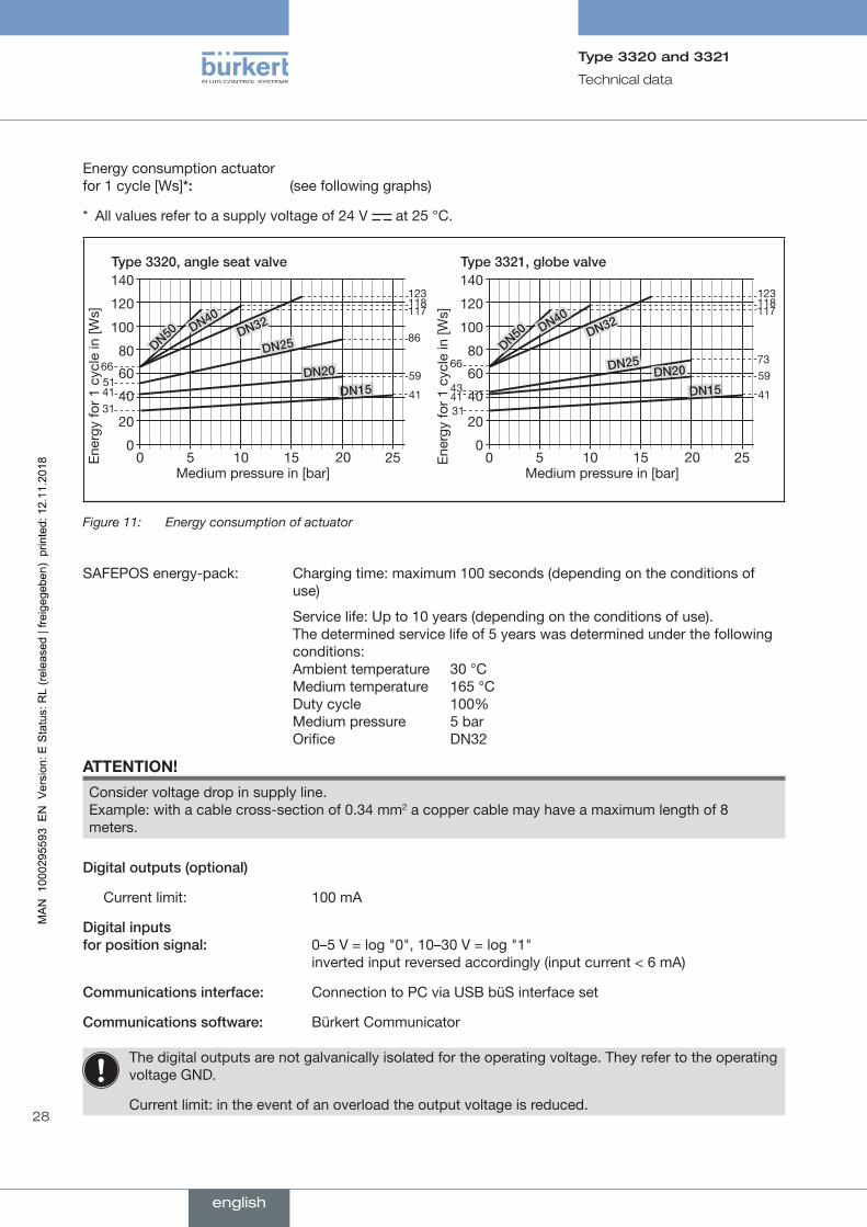
Energy consumption actuator for 1 cycle [Ws]*: (see following graphs)
* All values refer to a supply voltage of 24 V at 25 °C.
140
120
100
80
60
40
20
00 5 10 15
Medium pressure in [bar]
Type3320,angleseatvalve
6651
117
86
59
41
DN32
DN50
DN25
DN20
DN40
DN15
2520
118123
3141
Ene
rgy
for
1 cy
cle
in [W
s]
140
120
100
80
60
40
20
00 5 10 15
Medium pressure in [bar]
Type3321,globevalve
66
43
117
7359
41
DN32
DN50
DN25DN20
DN40
DN15
2520
118123
3141
Ene
rgy
for
1 cy
cle
in [W
s]
Figure 11: Energy consumption of actuator
SAFEPOS energy-pack: Charging time: maximum 100 seconds (depending on the conditions of use)
Service life: Up to 10 years (depending on the conditions of use). The determined service life of 5 years was determined under the following conditions: Ambient temperature 30 °C Medium temperature 165 °C Duty cycle 100% Medium pressure 5 bar Orifice DN32
ATTENTION!
Consider voltage drop in supply line. Example: with a cable cross-section of 0.34 mm2 a copper cable may have a maximum length of 8 meters.
Digitaloutputs(optional)
Current limit: 100 mA
Digitalinputs forpositionsignal: 0–5 V = log "0", 10–30 V = log "1"
inverted input reversed accordingly (input current < 6 mA)
Communicationsinterface: Connection to PC via USB büS interface set
Communicationssoftware: Bürkert Communicator
The digital outputs are not galvanically isolated for the operating voltage. They refer to the operating voltage GND.
Current limit: in the event of an overload the output voltage is reduced.
english
29
Technical data
Type 3320 and 3321
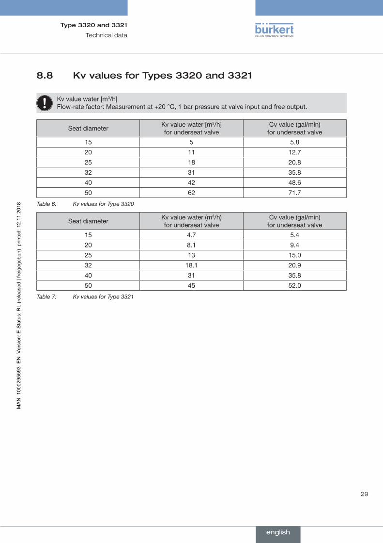
8.8 Kv values for Types 3320 and 3321
Kv value water [m3/h] Flow-rate factor: Measurement at +20 °C, 1 bar pressure at valve input and free output.
Seat diameter Kv value water [m3/h] for underseat valve
Cv value (gal/min) for underseat valve
15 5 5.8
20 11 12.7
25 18 20.8
32 31 35.8
40 42 48.6
50 62 71.7
Table 6: Kv values for Type 3320
Seat diameter Kv value water (m3/h) for underseat valve
Cv value (gal/min) for underseat valve
15 4.7 5.4
20 8.1 9.4
25 13 15.0
32 18.1 20.9
40 31 35.8
50 45 52.0
Table 7: Kv values for Type 3321
english
30
Installation of the valve
Type 3320 and 3321
9 INSTALLATION OF THE VALVE
9.1 Safety instructions
WARNING!
Riskofinjuryfromimproperassembly.
▶ The assembly may be carried out only by trained technicians and with the appropriate tools.
▶ Secure system against unintentional activation.
▶ After installation, ensure that the process is restarted in a controlled manner. Observe sequence. 1. Apply supply voltage. 2. Charge the device with medium.
CAUTION!
Riskofinjuryduetoaheavydevice.
The device can fall down during transport or during installation and cause injuries.
▶ Transport, install and dismantle a heavy device with the help of another person.
▶ Use appropriate tools.
9.2 Installation of devices with socket or flanged connection
ATTENTION!
Damagetovalvebody,seatsealordiaphragm.
▶ To prevent damage, the device must be in the MANUAL operating state during installation. Devices are delivered with the MANUAL operating state preset.
ATTENTION!
Notethefollowingwheninstallingthedeviceintheplant.
The device and the relief bore must be accessible to allow inspection and maintenance work.
9.2.1 Installation requirements
Installationposition: any position; preferably with actuator facing up.
Directionofflow: is specified on the rating plate by an arrow and the numbers 1 and 2. The 1 and the 2 stand for identification also on the valve body. The incoming flow is under the seat.
Pipelines: Ensure that the pipelines are aligned.
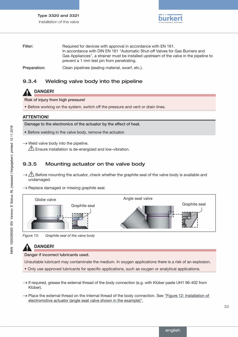
Filter: Required for devices with approval in accordance with EN 161. In accordance with DIN EN 161 "Automatic Shut-off Valves for Gas Burners and Gas Appliances", a strainer must be installed upstream of the valve in the pipeline to prevent a 1 mm test pin from penetrating.
Preparation: Clean pipelines (sealing material, swarf, etc.).
english
31
Installation of the valve
Type 3320 and 3321
9.2.2 Installation
DANGER!
Riskofinjuryfromhighpressure!
▶ Before working on the system, switch off the pressure and vent or drain lines.
WARNING!
Riskofcrushingduetomechanicallymovingparts.
▶ Keep clear of the openings in the valve body.
→ Connect valve body to pipeline. Ensure installation is de-energized and low-vibration.
Holdingdevice To protect the valve actuator from damage due to forces and oscillations, a holding device is recom-mended. This is available as an accessory. See chapter "20 Accessories, spare parts".
9.3 Installation of devices with welded housing
ATTENTION!
Damagetovalvebody,seatsealordiaphragm.
▶ To prevent damage, the device must be in the MANUAL operating state during installation. Devices are delivered with the MANUAL operating state preset.
ATTENTION!
Notethefollowingwheninstallingthedeviceintheplant.
The device and the relief bore must be accessible to allow inspection and maintenance work.
The device must not be welded into the pipeline with the actuator mounted. Installation is divided into the following steps:
1. Prepare removal of the actuator.
2. Remove the actuator.
3. Weld valve body into the pipeline.
4. Mount actuator on the valve body.
9.3.1 Preparing removal of the actuator
ATTENTION!
Damagetovalvebody,seatsealordiaphragm.
To prevent damage, the valve must be open when removing the actuator.
→ If the valve is closed: Open the valve using the mechanical manual control. See chapter "15.2 Actuating valve mechanically" on page 63.
english
32
Installation of the valve
Type 3320 and 3321
WARNING!
Riskofcrushingduetomechanicallymovingparts.
▶ Switch off supply voltage.
▶ Devices with SAFEPOS energy-pack: Completely drain SAFEPOS energy-pack. Wait until LED illumi-nated ring goes out; the LED status must not be in LEDoff mode.
▶ Keep clear of the openings in the valve body.
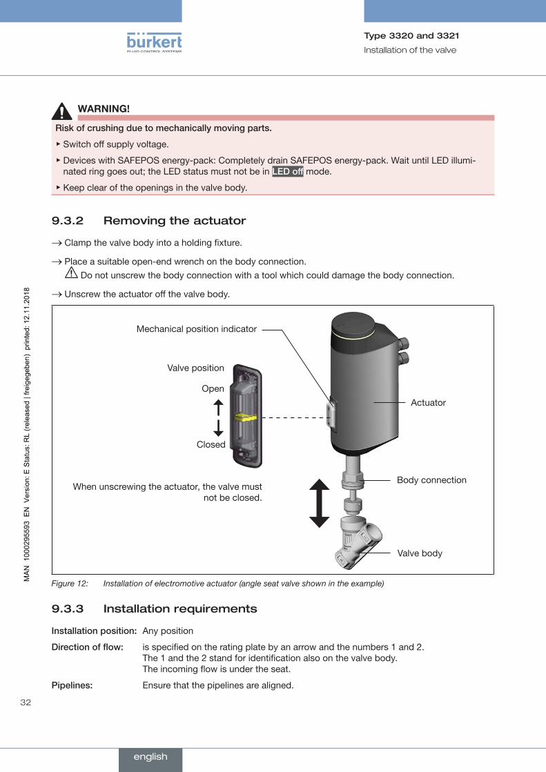
9.3.2 Removing the actuator
→ Clamp the valve body into a holding fixture.
→ Place a suitable open-end wrench on the body connection. Do not unscrew the body connection with a tool which could damage the body connection.
→ Unscrew the actuator off the valve body.
Mechanical position indicator
Valve position
Open
Closed
When unscrewing the actuator, the valve must not be closed.
Actuator
Body connection
Valve body
Figure 12: Installation of electromotive actuator (angle seat valve shown in the example)
9.3.3 Installation requirements
Installationposition: Any position
Directionofflow: is specified on the rating plate by an arrow and the numbers 1 and 2. The 1 and the 2 stand for identification also on the valve body. The incoming flow is under the seat.
Pipelines: Ensure that the pipelines are aligned.
english
33
Installation of the valve
Type 3320 and 3321
Filter: Required for devices with approval in accordance with EN 161. In accordance with DIN EN 161 "Automatic Shut-off Valves for Gas Burners and Gas Appliances", a strainer must be installed upstream of the valve in the pipeline to prevent a 1 mm test pin from penetrating.
Preparation: Clean pipelines (sealing material, swarf, etc.).
9.3.4 Welding valve body into the pipeline
DANGER!
Riskofinjuryfromhighpressure!
▶ Before working on the system, switch off the pressure and vent or drain lines.
ATTENTION!
Damagetotheelectronicsoftheactuatorbytheeffectofheat.
• Before welding in the valve body, remove the actuator.
→Weld valve body into the pipeline. Ensure installation is de-energized and low-vibration.
9.3.5 Mounting actuator on the valve body
→ Before mounting the actuator, check whether the graphite seal of the valve body is available and undamaged.
→ Replace damaged or missing graphite seal.
Graphite sealAngle seat valveGlobe valve
Graphite seal
Figure 13: Graphite seal of the valve body
DANGER!
Dangerifincorrectlubricantsused.
Unsuitable lubricant may contaminate the medium. In oxygen applications there is a risk of an explosion.
▶ Only use approved lubricants for specific applications, such as oxygen or analytical applications.
→ If required, grease the external thread of the body connection (e.g. with Klüber paste UH1 96-402 from Klüber).
→ Place the external thread on the internal thread of the body connection. See "Figure 12: Installation of electromotive actuator (angle seat valve shown in the example)".
english

34
Installation of the valve
Type 3320 and 3321
→ Place a suitable open-end wrench on the body connection. Do not screw on the body connection with a tool which could damage the body connection
(e.g. pipe wrench).
WARNING!
Riskofinjuryduetonon-observanceofthetighteningtorque.
Non-observance of the tightening torque is hazardous as the device may be damaged.
▶ Observe tightening torque.
→ Screw actuator onto the valve body.
Orificeconnection(valvebody)[DN] Tighteningtorqueforbodyconnection
[Nm] [lbfft]
10/15 45 ±3 33 ±2
20 50 ±3 37 ±2
25 60 ±3 44 ±2
3265 ±3 48 ±2
40
50 70 ±3 52 ±2
65 100 ±3 74 ±2
80 120 ±5 89 ±2
100 150 ±5 111 ±2
Table 8: Tightening torques for body connection
Holdingdevice To protect the valve actuator from damage due to forces and oscillations, a holding device is recom-mended. This is available as an accessory. See chapter "20 Accessories, spare parts".
9.3.6 After installation
→ Connect the device electrically.The position of the connections can be aligned by rotating the actuator through 360°. For description see chapter "9.4 Rotating the actuator".
A description of the electrical connection can be found in chapter "10 Electrical installation".
ATTENTION!
Damagetovalvebody,seatsealordiaphragm.
▶ To prevent damage, first run the X.TUNE function after making the electrical connection. Only then reset the operating state to AUTOMATIC.
→ Run X.TUNE function to adjust the end position. See chapter "11.4 Adjusting the position control – running the X.TUNE" on page 46.
english

35
Installation of the valve
Type 3320 and 3321
9.4 Rotating the actuatorThe position of the connections can be aligned by rotating the actuator through 360°.
ATTENTION!Damagetotheseatsealandseatcontourwhenvalveisclosed.
If the valve is closed when the actuator is rotated, the seat seal and the seat contour may be damaged.• If the valve is closed: Before rotating the actuator, open the valve using the mechanical manual control.
For description see "15.2 Actuating valve mechanically".
→ In the case of devices which are not installed, clamp the valve body in a holding device.
→ Place an open-end wrench (width across flats M41) on the hexagon of the actuator.
→ Rotate the actuator clockwise and move it into the required position.
If the actuator can be rotated only counter-clockwise for installation reasons, observe the following safety warning:
WARNING!
Riskofinjuryduetodischargeofmediumandpressurerelease.
If the actuator is rotated counter-clockwise, the body connection may become detached. ▶ When rotating the actuator counter-clockwise, counter with a 2nd open-end wrench on the hexagon of the body connection.
Hexagon on the actuator
Rotate clockwise
Hexagon of the body connection
Figure 14: Rotating the actuator
english
36
Installation of the valve
Type 3320 and 3321
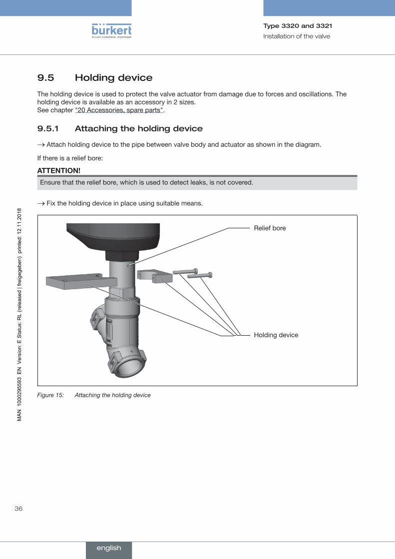
9.5 Holding device
The holding device is used to protect the valve actuator from damage due to forces and oscillations. The holding device is available as an accessory in 2 sizes. See chapter "20 Accessories, spare parts".
9.5.1 Attaching the holding device
→ Attach holding device to the pipe between valve body and actuator as shown in the diagram.
If there is a relief bore:
ATTENTION!
Ensure that the relief bore, which is used to detect leaks, is not covered.
→ Fix the holding device in place using suitable means.
Relief bore
Holding device
Figure 15: Attaching the holding device
english

37
Electrical installation
Type 3320 and 3321
10 ELECTRICAL INSTALLATIONThe electromotive valve is available with one of 2 different connection variants:
• With circular plug-in connector (multipole version)
• Cable gland with connection terminals
Signalvalues
Operating voltage: 24 V
Digital input for control signal: 0...5 V = log "0"; 10...30 V = log "1"
10.1 Electrical installation with circular plug-in connector
10.1.1 Safety instructions
WARNING!
Riskofinjuryfromimproperinstallation.
▶ Installation may be carried out by authorized technicians only and with the appropriate tools.
▶ Observe the general rules of technology during installation.
Riskofinjuryfromunintentionalactivationofthesystemanduncontrolledrestart.
▶ Secure system against unintentional activation.
▶ Following installation, ensure a controlled restart.
ATTENTION!To ensure electromagnetic compatibility (EMC), the functional ground must be grounded with a short cable (max. 1m). The functional ground must have a cross-section of at least 1.5 mm2.
Selectionoftheconnectionline: When selecting the length and cross-section of the individual wires, consider the voltage drop with reference to the maximum supply current.
→ Connect the device according to the tables.
→When the operating voltage has been applied, make the required basic settings and adjustments for the electromotive valve. For description see chapter "11 Starting up".
english
38
Electrical installation
Type 3320 and 3321
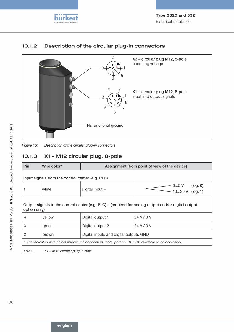
10.1.2 Description of the circular plug-in connectors
FE functional ground
1
2
3
45
1
23
4
56
78
X3–circularplugM12,5-pole operating voltage
X1–circularplugM12,8-pole input and output signals
Figure 16: Description of the circular plug-in connectors
10.1.3 X1 – M12 circular plug, 8-pole
Pin Wirecolor* Assignment(frompointofviewofthedevice)
Inputsignalsfromthecontrolcenter(e.g.PLC)
1 white Digital input + 0...5 V (log. 0)10...30 V (log. 1)
Outputsignalstothecontrolcenter(e.g.PLC)–(requiredforanalogoutputand/ordigitaloutput optiononly)
4 yellow Digital output 1 24 V / 0 V
3 green Digital output 2 24 V / 0 V
2 brown Digital inputs and digital outputs GND
* The indicated wire colors refer to the connection cable, part no. 919061, available as an accessory.
Table 9: X1 – M12 circular plug, 8-pole
english
39
Electrical installation
Type 3320 and 3321
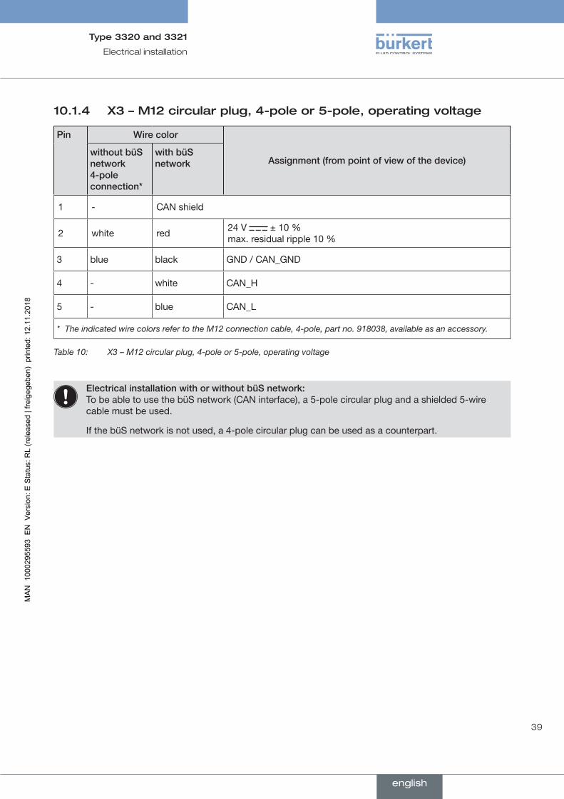
10.1.4 X3 – M12 circular plug, 4-pole or 5-pole, operating voltage
Pin Wirecolor
Assignment(frompointofviewofthedevice)withoutbüSnetwork4-poleconnection*
withbüSnetwork
1 - CAN shield
2 white red 24 V ± 10 % max. residual ripple 10 %
3 blue black GND / CAN_GND
4 - white CAN_H
5 - blue CAN_L
* The indicated wire colors refer to the M12 connection cable, 4-pole, part no. 918038, available as an accessory.
Table 10: X3 – M12 circular plug, 4-pole or 5-pole, operating voltage
ElectricalinstallationwithorwithoutbüSnetwork: To be able to use the büS network (CAN interface), a 5-pole circular plug and a shielded 5-wire cable must be used.
If the büS network is not used, a 4-pole circular plug can be used as a counterpart.
english
40
Electrical installation
Type 3320 and 3321
10.2 Electrical installation with cable gland
10.2.1 Safety instructions
WARNING!
Riskofinjuryfromimproperinstallation.
▶ Installation may be carried out by authorized technicians only and with the appropriate tools.
▶ Observe the general rules of technology during installation.
Riskofinjuryfromunintentionalactivationofthesystemanduncontrolledrestart.
▶ Secure system against unintentional activation.
▶ Following installation, ensure a controlled restart.
ATTENTION!To ensure electromagnetic compatibility (EMC), the functional ground must be grounded with a short cable (max. 1m). The functional ground must have a cross-section of at least 1.5 mm2.
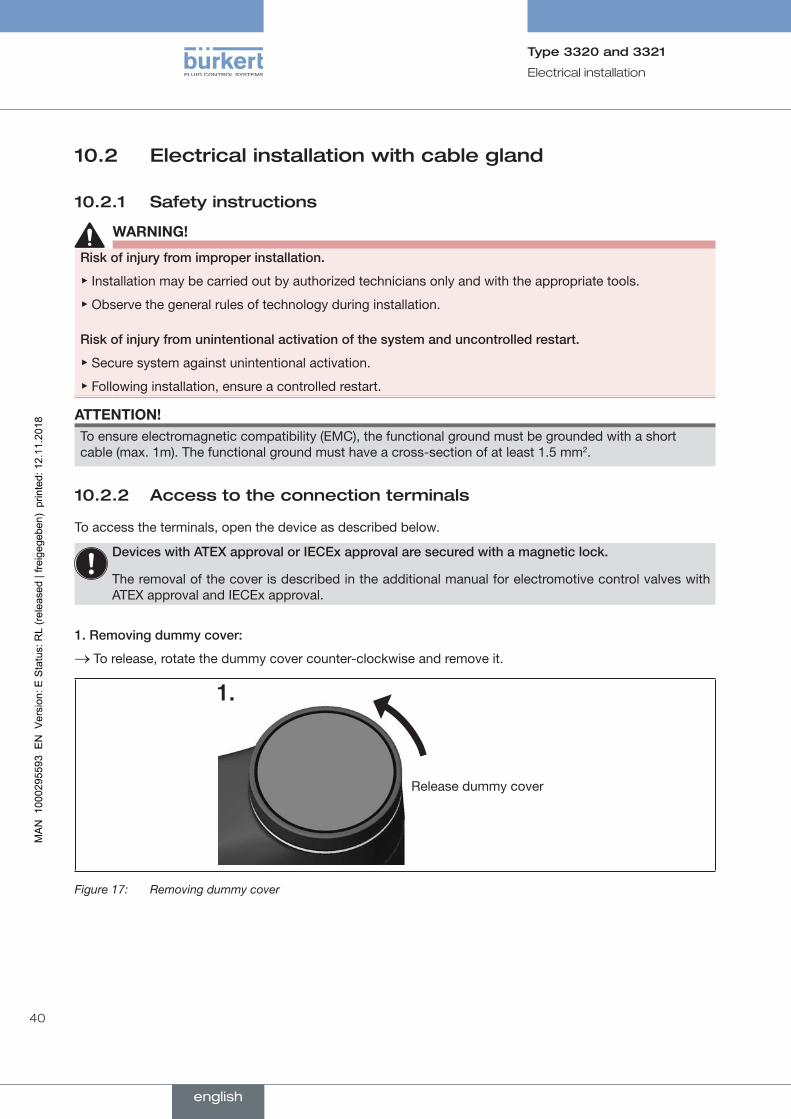
10.2.2 Access to the connection terminals
To access the terminals, open the device as described below.
DeviceswithATEXapprovalorIECExapprovalaresecuredwithamagneticlock.
The removal of the cover is described in the additional manual for electromotive control valves with ATEX approval and IECEx approval.
1.Removingdummycover:
→ To release, rotate the dummy cover counter-clockwise and remove it.
Release dummy cover
Figure 17: Removing dummy cover
english

41
Electrical installation
Type 3320 and 3321
2.RemovingLEDandstoragemodule:
→ Remove the 2 fastening screws (hexagon head key, width across flats 3 mm).
→ Take hold of the LED and storage module on both sides of the metal housing and lift out.
Metal housing of the LED and storage module
Fastening screws
Fastening screws
Removing LED and storage module: Removing actuator cover:
Actuator cover
Figure 18: Remove LED and storage module and remove actuator cover
3.Removingactuatorcover:
→ Loosen the 4 fastening screws (T25 hexagonal socket round screws). The screws are integrated in the actuator cover to prevent them from falling out.
→ Remove the actuator cover.
The connection terminals are now accessible.
10.2.3 Connecting the cables
→ Push the cables through the cable gland.
ATTENTION!
Allowforconnectiontospring-typeterminals.
▶ Minimum length of the wire end ferrule: 8 mm
▶ Maximum cross-section of the wire end ferrule: 1.5 mm2 (without collar), 0.75 mm2 (with collar).
→ Strip at least 8 mm insulation from the wires and crimp on wire end ferrules.
→ Connect the wires. The terminal assignment can be found in the tables below, starting on Page 43.
→ Tighten the union nut of the cable gland (tightening torque approx. 1.5 Nm (1.1 lbf ft)).
english
42
Electrical installation
Type 3320 and 3321
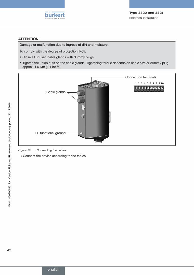
ATTENTION!
Damageormalfunctionduetoingressofdirtandmoisture.
To comply with the degree of protection IP65:
▶ Close all unused cable glands with dummy plugs.
▶ Tighten the union nuts on the cable glands. Tightening torque depends on cable size or dummy plug approx. 1.5 Nm (1.1 lbf ft).
Connection terminals
Cable glands
FE functional ground
Figure 19: Connecting the cables
→ Connect the device according to the tables.
english
43
Electrical installation
Type 3320 and 3321
10.2.4 Terminal assignment – input signal from the control center (e.g. PLC)
Terminal Assignment(frompointofviewofthedevice)
5 Digital input + + 0...5 V (log. 0)
10...30 V (log. 1)
4 Digital input GND specific to operating voltage GND (terminal GND)
8 Digital output 1 24 V / 0 V
6 Digital output 2 24 V / 0 V
7 Digital output GND
Table 11: Terminal assignment – input signal from the control center (e.g. PLC)
10.2.5 Terminal assignment – operating voltage and büS network
Terminal Assignment(frompointofviewofthedevice)
CAN shield
10 24 V ± 10 % max. residual ripple 10 %
9 GND
1*CAN_GND
Do not connect unless a separate line is used for CAN.
2* CAN_H
3* CAN_L
Table 12: Terminal assignment – operating voltage and büS network
*ElectricalinstallationofbüSnetwork: Terminals 1, 2 and 3 (CAN interface) are for the connection of the büS network. Terminal 1 is bridged internally with terminal 9, but is not designed for the operating voltage.
english
44
Electrical installation
Type 3320 and 3321
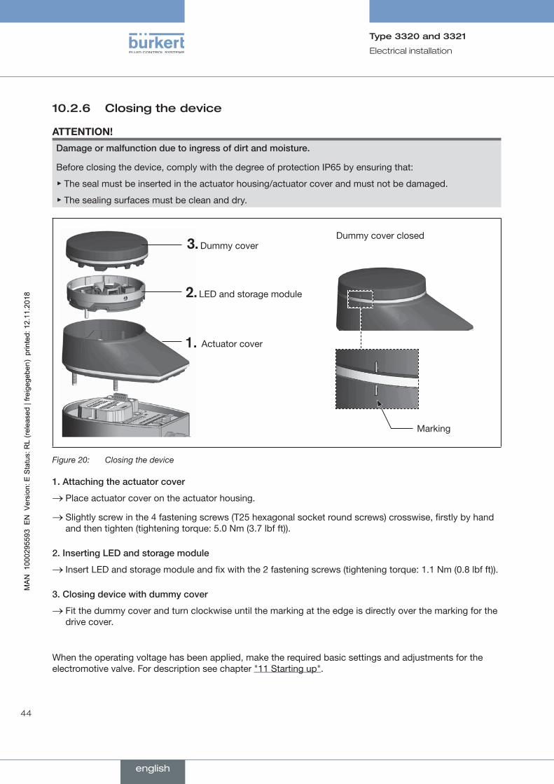
10.2.6 Closing the device
ATTENTION!
Damageormalfunctionduetoingressofdirtandmoisture.
Before closing the device, comply with the degree of protection IP65 by ensuring that:
▶ The seal must be inserted in the actuator housing/actuator cover and must not be damaged.
▶ The sealing surfaces must be clean and dry.
Dummy cover
Actuator cover
LED and storage module
Dummy cover closed
Marking
Figure 20: Closing the device
1.Attachingtheactuatorcover
→ Place actuator cover on the actuator housing.
→ Slightly screw in the 4 fastening screws (T25 hexagonal socket round screws) crosswise, firstly by hand and then tighten (tightening torque: 5.0 Nm (3.7 lbf ft)).
2.InsertingLEDandstoragemodule
→ Insert LED and storage module and fix with the 2 fastening screws (tightening torque: 1.1 Nm (0.8 lbf ft)).
3.Closingdevicewithdummycover
→ Fit the dummy cover and turn clockwise until the marking at the edge is directly over the marking for the drive cover.
When the operating voltage has been applied, make the required basic settings and adjustments for the electromotive valve. For description see chapter "11 Starting up".
english
45
Starting up
Type 3320 and 3321
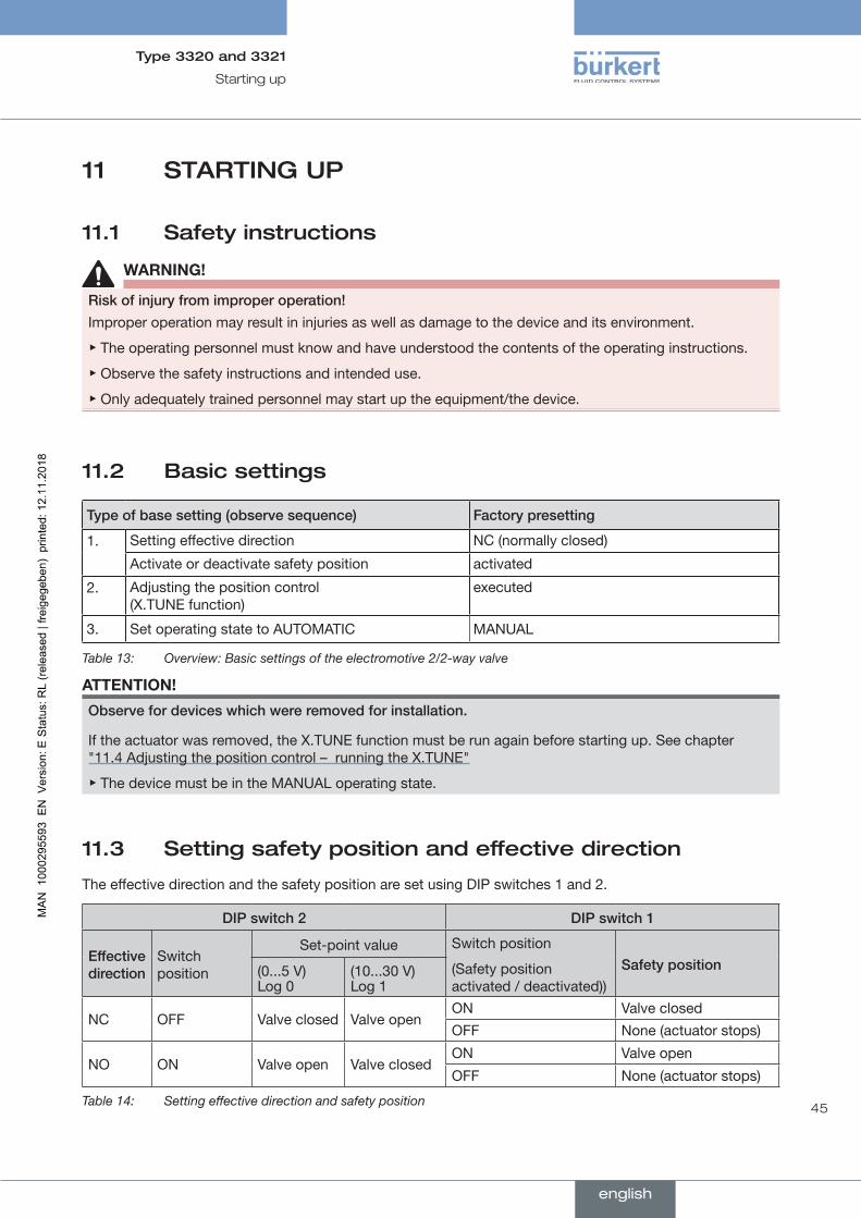
11 STARTING UP
11.1 Safety instructions
WARNING!
Riskofinjuryfromimproperoperation!
Improper operation may result in injuries as well as damage to the device and its environment.
▶ The operating personnel must know and have understood the contents of the operating instructions.
▶ Observe the safety instructions and intended use.
▶ Only adequately trained personnel may start up the equipment/the device.
11.2 Basic settings
Typeofbasesetting(observesequence) Factorypresetting
1. Setting effective direction NC (normally closed)
Activate or deactivate safety position activated
2. Adjusting the position control (X.TUNE function)
executed
3. Set operating state to AUTOMATIC MANUAL
Table 13: Overview: Basic settings of the electromotive 2/2-way valve
ATTENTION!
Observefordeviceswhichwereremovedforinstallation.
If the actuator was removed, the X.TUNE function must be run again before starting up. See chapter "11.4 Adjusting the position control – running the X.TUNE"
▶ The device must be in the MANUAL operating state.
11.3 Setting safety position and effective direction
The effective direction and the safety position are set using DIP switches 1 and 2.
DIPswitch2 DIPswitch1
Effectivedirection
Switch position
Set-point value Switch position
(Safety position activated / deactivated))
Safetyposition(0...5 V) Log 0
(10...30 V) Log 1
NC OFF Valve closed Valve openON Valve closed
OFF None (actuator stops)
NO ON Valve open Valve closedON Valve open
OFF None (actuator stops)
Table 14: Setting effective direction and safety position
english
46
Starting up
Type 3320 and 3321
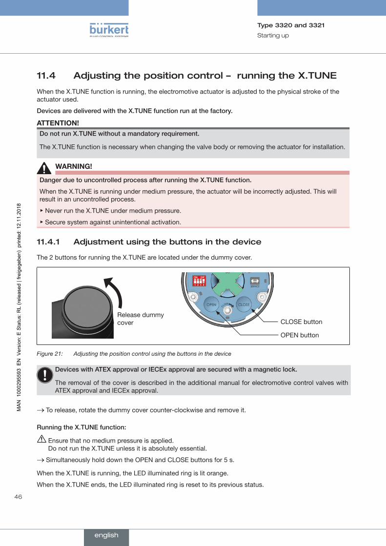
11.4 Adjusting the position control – running the X.TUNE
When the X.TUNE function is running, the electromotive actuator is adjusted to the physical stroke of the actuator used.
DevicesaredeliveredwiththeX.TUNEfunctionrunatthefactory.
ATTENTION!DonotrunX.TUNEwithoutamandatoryrequirement.
The X.TUNE function is necessary when changing the valve body or removing the actuator for installation.
WARNING!
DangerduetouncontrolledprocessafterrunningtheX.TUNEfunction.
When the X.TUNE is running under medium pressure, the actuator will be incorrectly adjusted. This will result in an uncontrolled process.
▶ Never run the X.TUNE under medium pressure.
▶ Secure system against unintentional activation.
11.4.1 Adjustment using the buttons in the device
The 2 buttons for running the X.TUNE are located under the dummy cover.
Release dummy cover CLOSE button
OPEN button
Figure 21: Adjusting the position control using the buttons in the device
DeviceswithATEXapprovalorIECExapprovalaresecuredwithamagneticlock.
The removal of the cover is described in the additional manual for electromotive control valves with ATEX approval and IECEx approval.
→ To release, rotate the dummy cover counter-clockwise and remove it.
RunningtheX.TUNEfunction:
Ensure that no medium pressure is applied. Do not run the X.TUNE unless it is absolutely essential.
→ Simultaneously hold down the OPEN and CLOSE buttons for 5 s.
When the X.TUNE is running, the LED illuminated ring is lit orange.
When the X.TUNE ends, the LED illuminated ring is reset to its previous status.
english
47
Starting up
Type 3320 and 3321
11.4.2 Adjustment of the position control on the PC
The setting is made on the PC via the büS service interface and by using the "Bürkert Communi-cator" PC software. To do this, the USB büS interface set, available as an accessory, is required.
To run the X.TUNE function, you must change to the detailed view maintenance for position controller.
Switchtothedetailedviewasfollows:
→ Select Positioncontroller.
→ Switch to MAINTENANCE.
You are in the detailed view maintenance.
RunningtheX.TUNEfunction:
Ensure that no medium pressure is applied.
→ Select CALIBRATION.
→ Select X.TUNE.
The following text appears: "Choose seal material (see type label)!"
→ Choose seal material.
The following question appears: "Do you really want to start the X.TUNE?" Do not confirm the question unless it is absolutely essential to run the X.TUNE.
→ Start X.TUNE.
The X.TUNE function is running.
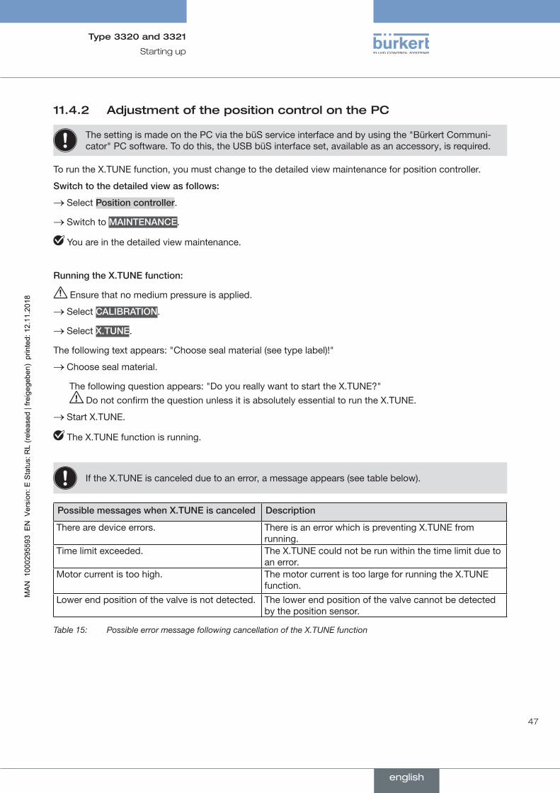
If the X.TUNE is canceled due to an error, a message appears (see table below).
PossiblemessageswhenX.TUNEiscanceled Description
There are device errors. There is an error which is preventing X.TUNE from running.
Time limit exceeded. The X.TUNE could not be run within the time limit due to an error.
Motor current is too high. The motor current is too large for running the X.TUNE function.
Lower end position of the valve is not detected. The lower end position of the valve cannot be detected by the position sensor.
Table 15: Possible error message following cancellation of the X.TUNE function
english
48
Starting up
Type 3320 and 3321
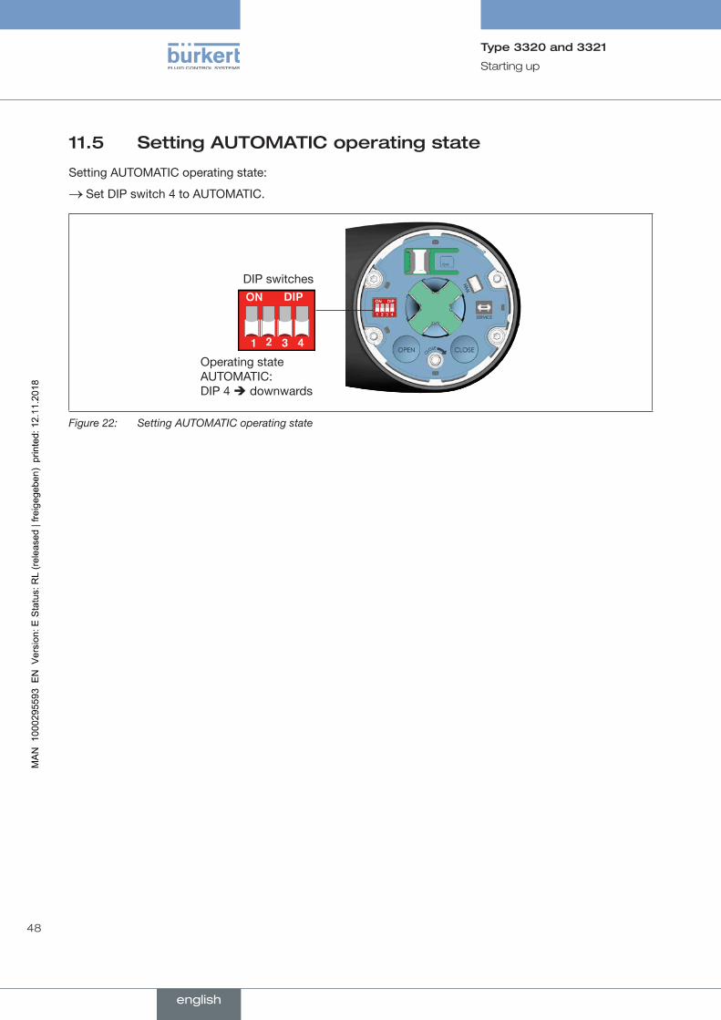
11.5 Setting AUTOMATIC operating state
Setting AUTOMATIC operating state:
→ Set DIP switch 4 to AUTOMATIC.
Operating state AUTOMATIC: DIP 4 downwards
DIP switches
Figure 22: Setting AUTOMATIC operating state
english
49
Operation
Type 3320 and 3321
12 OPERATION
WARNING!
Dangerduetoimproperoperation.
Improper operation may result in injuries as well as damage to the device and its environment.
▶ The operating personnel must know and have understood the contents of the operating instructions.
▶ Observe the safety instructions and intended use.
▶ Only adequately trained personnel may operate the equipment/the device.
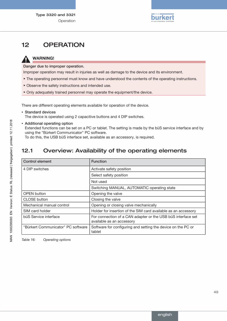
There are different operating elements available for operation of the device.
• Standarddevices The device is operated using 2 capacitive buttons and 4 DIP switches.
• Additionaloperatingoption Extended functions can be set on a PC or tablet. The setting is made by the büS service interface and by using the "Bürkert Communicator" PC software. To do this, the USB büS interface set, available as an accessory, is required.
12.1 Overview: Availability of the operating elements
Controlelement Function
4 DIP switches Activate safety position
Select safety position
Not used
Switching MANUAL, AUTOMATIC operating stateOPEN button Opening the valveCLOSE button Closing the valveMechanical manual control Opening or closing valve mechanicallySIM card holder Holder for insertion of the SIM card available as an accessorybüS Service interface For connection of a CAN adapter or the USB büS interface set
available as an accessory"Bürkert Communicator" PC software Software for configuring and setting the device on the PC or
tablet
Table 16: Operating options
english
50
Operation
Type 3320 and 3321
12.2 Display elements
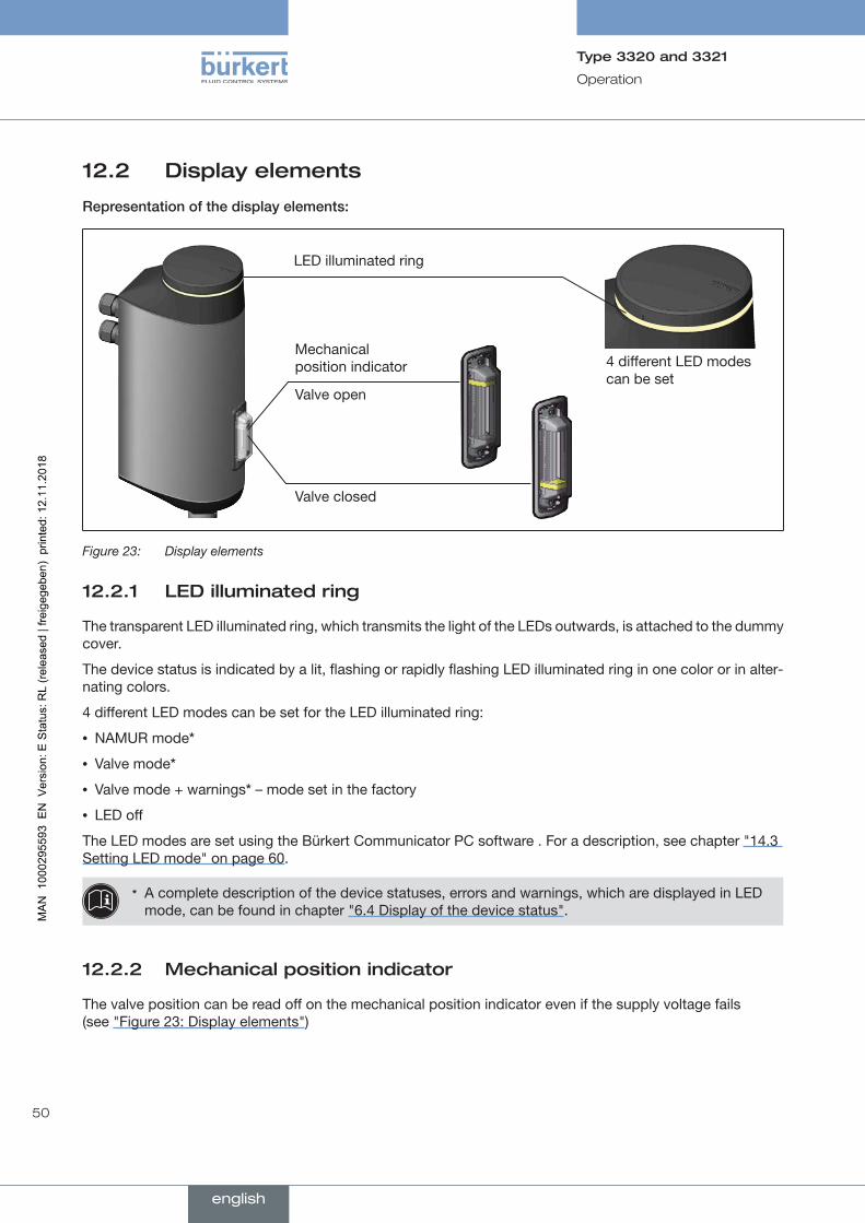
Representationofthedisplayelements:
LED illuminated ring
Valve open
Valve closed
Mechanical position indicator 4 different LED modes
can be set
Figure 23: Display elements
12.2.1 LED illuminated ring
The transparent LED illuminated ring, which transmits the light of the LEDs outwards, is attached to the dummy cover.
The device status is indicated by a lit, flashing or rapidly flashing LED illuminated ring in one color or in alter-nating colors.
4 different LED modes can be set for the LED illuminated ring:
• NAMUR mode*
• Valve mode*
• Valve mode + warnings* – mode set in the factory
• LED off
The LED modes are set using the Bürkert Communicator PC software . For a description, see chapter "14.3 Setting LED mode" on page 60.
* A complete description of the device statuses, errors and warnings, which are displayed in LED mode, can be found in chapter "6.4 Display of the device status".
12.2.2 Mechanical position indicator
The valve position can be read off on the mechanical position indicator even if the supply voltage fails (see "Figure 23: Display elements")
english

51
Operation
Type 3320 and 3321
12.3 Operating elements
Representationoftheoperatingelements:
DIP switches
SIM card
CLOSE button
büS Service interface
OPEN button
Mechanical manual control
Figure 24: Operating elements
12.3.1 DIP switches
Settings
Switch 1: Activate or deactivate safety position, see chapter "13.2" on page 57.
Switch 2: Select safety position between NO and NC, see chapter "13.2" on page 57.
Switch 3: Not used.
Switch 4: For switching between AUTOMATIC mode and MANUAL mode. See chapter "13.1" on page 56.
12.3.2 OPEN button and CLOSE button
Electrical manual control: Open valve: Press OPEN button Close valve: Press CLOSE button
Running X.TUNE (Autotune): For description see chapter "11.4 Adjusting the position control – running the X.TUNE".
12.3.3 Mechanical manual control
When the supply voltage is not applied, e.g. during installation or in the event of a power failure, the valve can be opened or closed with the mechanical manual control.
For description see chapter "15.2 Actuating valve mechanically".
english
52
Operation
Type 3320 and 3321
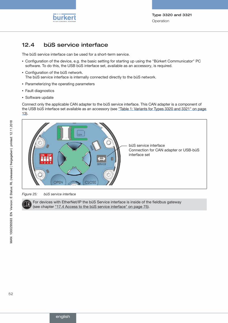
12.4 büS service interface
The büS service interface can be used for a short-term service.
• Configuration of the device, e.g. the basic setting for starting up using the "Bürkert Communicator" PC software. To do this, the USB büS interface set, available as an accessory, is required.
• Configuration of the büS network. The büS service interface is internally connected directly to the büS network.
• Parameterizing the operating parameters
• Fault diagnostics
• Software update
Connect only the applicable CAN adapter to the büS service interface. This CAN adapter is a component of the USB büS interface set available as an accessory (see "Table 1: Variants for Types 3320 and 3321" on page 13).
büS service interface Connection for CAN adapter or USB-büS interface set
Figure 25: büS service interface
For devices with EtherNet/IP the büS Service interface is inside of the fieldbus gateway (see chapter "17.4 Access to the büS service interface" on page 75).
english
53
Operation
Type 3320 and 3321
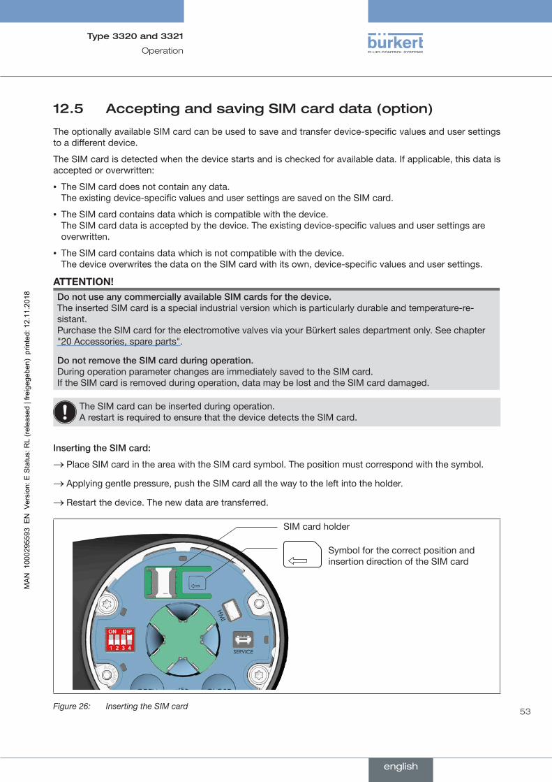
12.5 Accepting and saving SIM card data (option)
The optionally available SIM card can be used to save and transfer device-specific values and user settings to a different device.
The SIM card is detected when the device starts and is checked for available data. If applicable, this data is accepted or overwritten:
• The SIM card does not contain any data. The existing device-specific values and user settings are saved on the SIM card.
• The SIM card contains data which is compatible with the device. The SIM card data is accepted by the device. The existing device-specific values and user settings are overwritten.
• The SIM card contains data which is not compatible with the device. The device overwrites the data on the SIM card with its own, device-specific values and user settings.
ATTENTION!DonotuseanycommerciallyavailableSIMcardsforthedevice. The inserted SIM card is a special industrial version which is particularly durable and temperature-re-sistant. Purchase the SIM card for the electromotive valves via your Bürkert sales department only. See chapter "20 Accessories, spare parts".
DonotremovetheSIMcardduringoperation. During operation parameter changes are immediately saved to the SIM card. If the SIM card is removed during operation, data may be lost and the SIM card damaged.
The SIM card can be inserted during operation. A restart is required to ensure that the device detects the SIM card.
InsertingtheSIMcard:
→ Place SIM card in the area with the SIM card symbol. The position must correspond with the symbol.
→ Applying gentle pressure, push the SIM card all the way to the left into the holder.
→ Restart the device. The new data are transferred.
Symbol for the correct position and insertion direction of the SIM card
SIM card holder
Figure 26: Inserting the SIM card
english
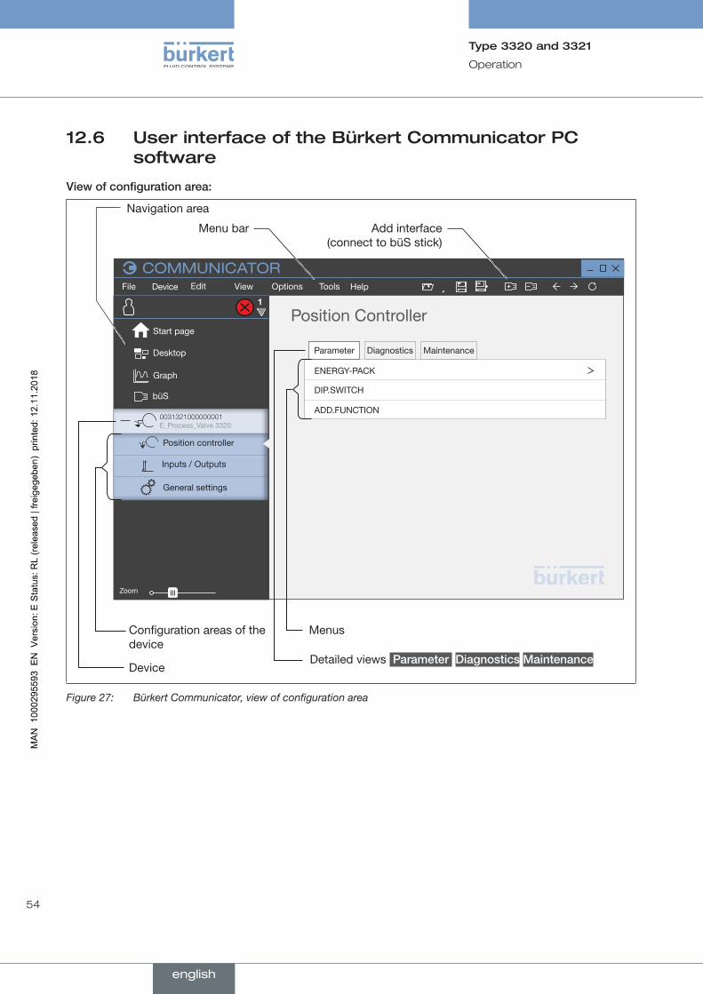
54
Operation
Type 3320 and 3321
12.6 User interface of the Bürkert Communicator PC software
Viewofconfigurationarea:
100%
Menu bar Add interface (connect to büS stick)
Configuration areas of the device
Menus
Detailed views Parameter Diagnostics Maintenance
Navigation area
Device
Zoom
Desktop
Graph
büS
File Edit View Options
COMMUNICATORTools HelpDevice
General settings
Position Controller
Parameter Diagnostics Maintenance
ENERGY-PACK
DIP.SWITCH
ADD.FUNCTION
1
Start page
0031321000000001 E_Process_Valve 3320
Position controller
Inputs / Outputs
Figure 27: Bürkert Communicator, view of configuration area
english
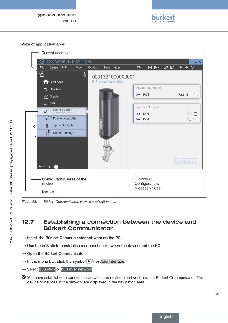
55
Operation
Type 3320 and 3321
Viewofapplicationarea:
100%
Configuration areas of the device
Current user level
Device
Zoom
Desktop
Graph
büS
File Edit View Options
COMMUNICATORTools HelpDevice
General settings
0031321000000001 E_Process_Valve 3320
1
Start page
0031321000000001 E_Process_Valve 3320
Position controller
Inputs / Outputs
Position controller
Inputs / Outputs
POS 73,7%
DO1 0
DO1 0
Overview: Configuration, process values
Figure 28: Bürkert Communicator, view of application area
12.7 Establishing a connection between the device and Bürkert Communicator
→ InstalltheBürkertCommunicatorsoftwareonthePC.
→ UsethebüSsticktoestablishaconnectionbetweenthedeviceandthePC.
→ OpentheBürkertCommunicator.
→ Inthemenubar,clickthesymbol forAddinterface.
→ Select büSstick or büSovernetwork.
You have established a connection between the device or network and the Bürkert Communicator. The device or devices in the network are displayed in the navigation area.
english
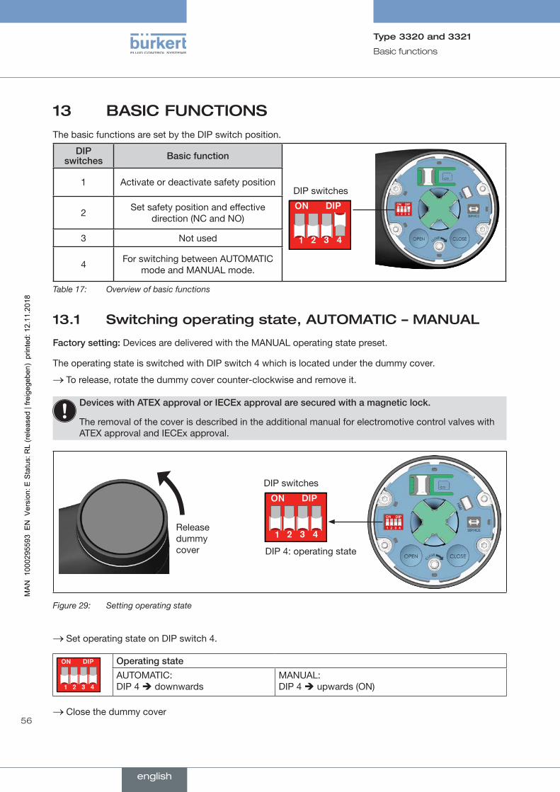
56
Basic functions
Type 3320 and 3321
13 BASIC FUNCTIONSThe basic functions are set by the DIP switch position.
DIP switches Basicfunction
DIP switches1 Activate or deactivate safety position
2 Set safety position and effective direction (NC and NO)
3 Not used
4 For switching between AUTOMATIC mode and MANUAL mode.
Table 17: Overview of basic functions
13.1 Switching operating state, AUTOMATIC – MANUAL
Factorysetting: Devices are delivered with the MANUAL operating state preset.
The operating state is switched with DIP switch 4 which is located under the dummy cover.
→ To release, rotate the dummy cover counter-clockwise and remove it.
DeviceswithATEXapprovalorIECExapprovalaresecuredwithamagneticlock.
The removal of the cover is described in the additional manual for electromotive control valves with ATEX approval and IECEx approval.
Release dummy cover DIP 4: operating state
DIP switches
Figure 29: Setting operating state
→ Set operating state on DIP switch 4.
Operatingstate
AUTOMATIC: DIP 4 downwards
MANUAL: DIP 4 upwards (ON)
→ Close the dummy cover
english
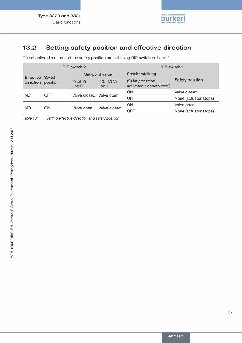
57
Basic functions
Type 3320 and 3321
13.2 Setting safety position and effective direction
The effective direction and the safety position are set using DIP switches 1 and 2.
DIPswitch2 DIPswitch1
Effectivedirection
Switch position
Set-point value Schalterstellung
(Safety position activated / deactivated))
Safetyposition(0...5 V) Log 0
(10...30 V) Log 1
NC OFF Valve closed Valve openON Valve closed
OFF None (actuator stops)
NO ON Valve open Valve closedON Valve open
OFF None (actuator stops)
Table 18: Setting effective direction and safety position
english

58
Basic functions
Type 3320 and 3321
14 EXTENDED FUNCTIONS
14.1 X.TIME – Limiting the control speed
Use this auxiliary function to specify the opening and closing times for the entire stroke and limit the control speeds.
When the X.TUNE function is running, the minimum opening and closing time for the entire stroke is automatically entered for Open and Close. Therefore, movement can be at maximum speed.
Factory setting: values determined at the factory by the X.TUNE function
If the control speed is limited, values can be input for Open and Close which are between the minimum values determined by the X.TUNE and 60 s.
Effectoflimitingtheopeningspeedwhenthereisajumpintheset-pointvalue
Set-point value
Actual value
Opent
Valve stroke [%] (POS, CMD)
Figure 30: X.TIME graph
SettingwiththePCsoftwareBürkertCommunicatoronthePC:
The PC software Bürkert Communicator can be downloaded free of charge from the Bürkert homepage. To do this, the USB büS interface set, available as an accessory, is required. Communication is established by the büS service interface of the device.
The setting is made in the detailed view parameters for position controller.
Activatingthelimitactuatingtime:
→ Select Positioncontroller.
→ Select ADD.FUNCTION.
→ Select X.TIME.
The limit actuating time is activated and the menu X.TIME for configuration is now available.
Configuringthelimitactuatingtime:
→ In the detailed view parameter select X.TIME.
english
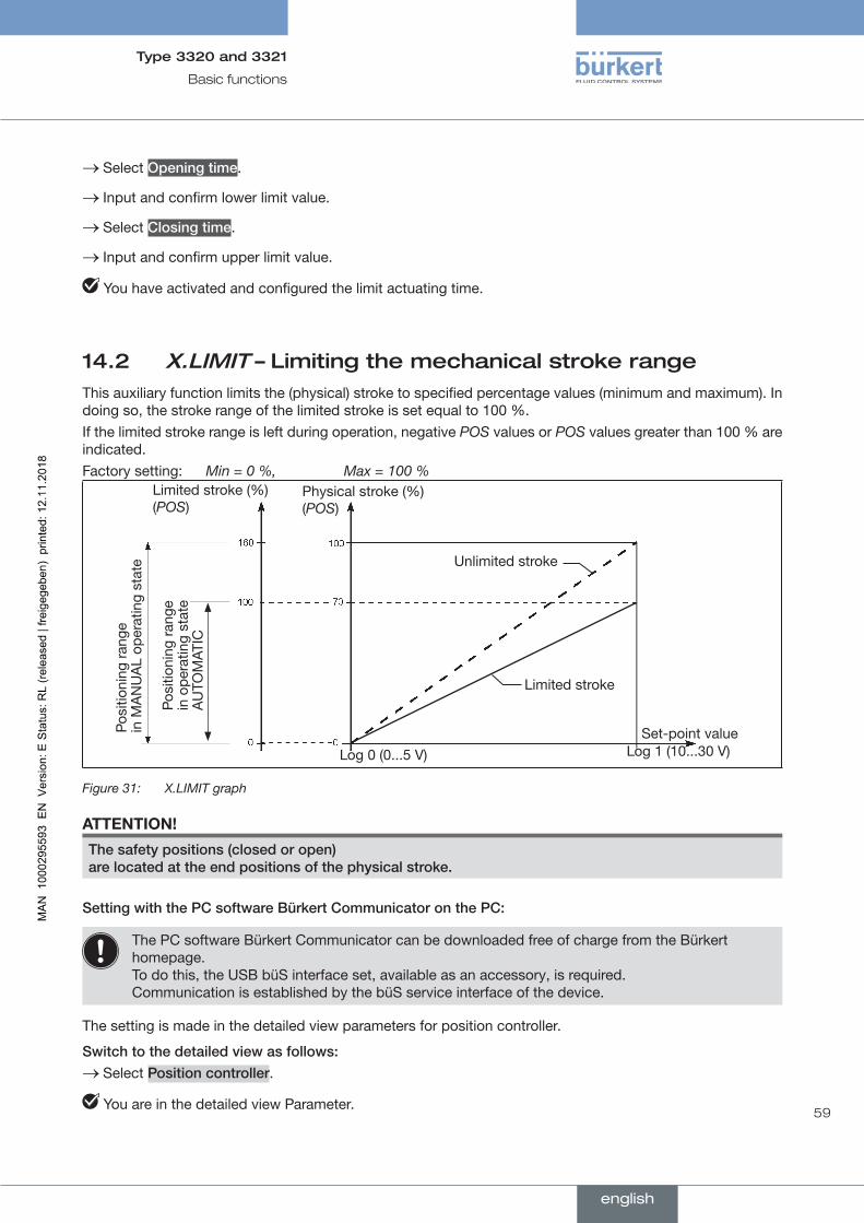
59
Basic functions
Type 3320 and 3321
→ Select Openingtime.
→ Input and confirm lower limit value.
→ Select Closingtime.
→ Input and confirm upper limit value.
You have activated and configured the limit actuating time.
14.2 X.LIMIT – Limiting the mechanical stroke rangeThis auxiliary function limits the (physical) stroke to specified percentage values (minimum and maximum). In doing so, the stroke range of the limited stroke is set equal to 100 %. If the limited stroke range is left during operation, negative POS values or POS values greater than 100 % are indicated.Factory setting: Min = 0 %, Max = 100 %
Physical stroke (%) (POS)
Limited stroke (%) (POS)
Set-point valuePosi
tioni
ng ra
nge
in M
AN
UA
L op
erat
ing
stat
e
Posi
tioni
ng ra
nge
in o
pera
ting
stat
e A
UTO
MA T
IC
Unlimited stroke
Limited stroke
Log 0 (0...5 V) Log 1 (10...30 V)
Figure 31: X.LIMIT graph
ATTENTION!
Thesafetypositions(closedoropen) arelocatedattheendpositionsofthephysicalstroke.
SettingwiththePCsoftwareBürkertCommunicatoronthePC:
The PC software Bürkert Communicator can be downloaded free of charge from the Bürkert homepage. To do this, the USB büS interface set, available as an accessory, is required. Communication is established by the büS service interface of the device.
The setting is made in the detailed view parameters for position controller.
Switchtothedetailedviewasfollows: → Select Positioncontroller.
You are in the detailed view Parameter.
english
60
Basic functions
Type 3320 and 3321
Activatingthemechanicalstrokelimit:
→ Select ADD.FUNCTION.
→ Select X.LIMIT.
The mechanical stroke limit is activated and the menu X.LIMIT for configuration is now available.
Configuringthemechanicalstrokelimit: → In the detailed view parameter select X.LIMIT.
→ Select Maximum.
→ Input and confirm upper limit value.
You have activated and configured the mechanical stroke limit.
14.3 Setting LED mode
SettingwiththePCsoftwareBürkertCommunicatoronthePC:
The PC software Bürkert Communicator can be downloaded free of charge from the Bürkert homepage.
To do this, the USB büS interface set, available as an accessory, is required. Communication is established by the büS service interface of the device.
The setting is made in the detailed view parameters for general settings.
Switchtothedetailedviewasfollows:
→ Select Generalsettings.
You are in the detailed view Parameter.
SettingtheLEDmode:
→ Select StatusLED.
→ Select Mode.
The following LED modes can be selected:NAMURmode
Valvemode
Valvemode+warnings
LEDoff
You have set LED mode.
english

61
Basic functions
Type 3320 and 3321
14.4 Setting the colors for indicating the valve position
The colours on the LED light ring that indicate the valve positions can be set individually.
SettingwiththePCsoftwareBürkertCommunicatoronthePC:
The PC software Bürkert Communicator can be downloaded free of charge from the Bürkert homepage.
To do this, the USB büS interface set, available as an accessory, is required. Communication is established by the büS service interface of the device.
The setting is made in the detailed view parameters for general settings.
Switchtothedetailedviewasfollows: → Select Generalsettings.
You are in the detailed view Parameter.
Howtosetthecolourforthevalveposition.
→ Select StatusLED.
→ Select Valvemode or Valvemode+warnings.
→ In the submenus Valvemode and Valvemode+warnings, select the colour for the respective valve position.
You have set the colours that are used to indicate the valve positions on the LED light ring.
english
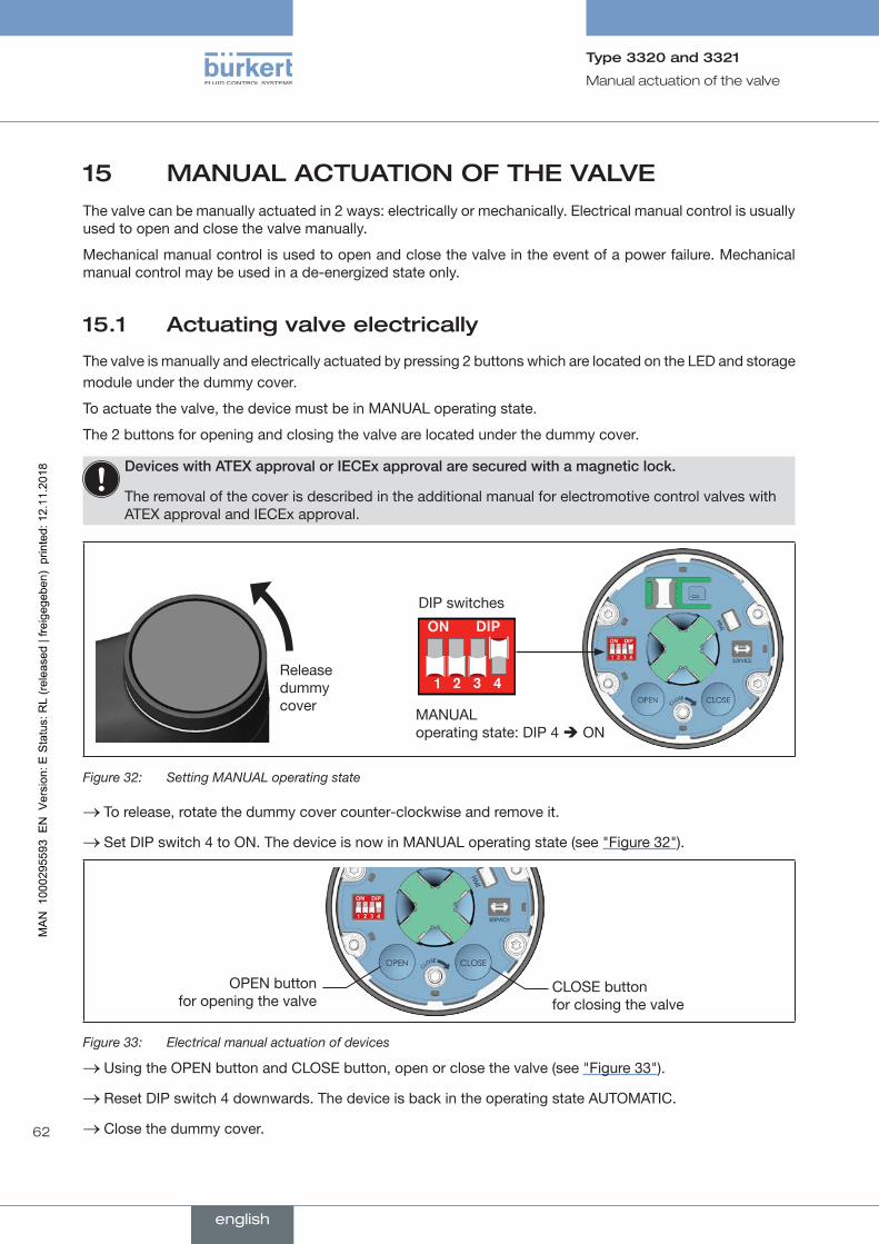
62
Manual actuation of the valve
Type 3320 and 3321
15 MANUAL ACTUATION OF THE VALVEThe valve can be manually actuated in 2 ways: electrically or mechanically. Electrical manual control is usually used to open and close the valve manually.
Mechanical manual control is used to open and close the valve in the event of a power failure. Mechanical manual control may be used in a de-energized state only.
15.1 Actuating valve electrically
The valve is manually and electrically actuated by pressing 2 buttons which are located on the LED and storage module under the dummy cover.
To actuate the valve, the device must be in MANUAL operating state.
The 2 buttons for opening and closing the valve are located under the dummy cover.
DeviceswithATEXapprovalorIECExapprovalaresecuredwithamagneticlock.
The removal of the cover is described in the additional manual for electromotive control valves with ATEX approval and IECEx approval.
MANUAL operating state: DIP 4 ON
DIP switches
Release dummy cover
Figure 32: Setting MANUAL operating state
→ To release, rotate the dummy cover counter-clockwise and remove it.
→ Set DIP switch 4 to ON. The device is now in MANUAL operating state (see "Figure 32").
OPEN button for opening the valve
CLOSE button for closing the valve
Figure 33: Electrical manual actuation of devices
→ Using the OPEN button and CLOSE button, open or close the valve (see "Figure 33").
→ Reset DIP switch 4 downwards. The device is back in the operating state AUTOMATIC.
→ Close the dummy cover.
english
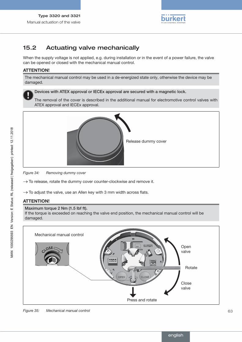
63
Manual actuation of the valve
Type 3320 and 3321
15.2 Actuating valve mechanically
When the supply voltage is not applied, e.g. during installation or in the event of a power failure, the valve can be opened or closed with the mechanical manual control.
ATTENTION!
The mechanical manual control may be used in a de-energized state only, otherwise the device may be damaged.
DeviceswithATEXapprovalorIECExapprovalaresecuredwithamagneticlock.
The removal of the cover is described in the additional manual for electromotive control valves with ATEX approval and IECEx approval.
Release dummy cover
Figure 34: Removing dummy cover
→ To release, rotate the dummy cover counter-clockwise and remove it.
→ To adjust the valve, use an Allen key with 3 mm width across flats.
ATTENTION!
Maximumtorque2Nm(1.5lbfft). If the torque is exceeded on reaching the valve end position, the mechanical manual control will be damaged.
Mechanical manual control
Press and rotate
Rotate
Open valve
Close valve
Figure 35: Mechanical manual control
english
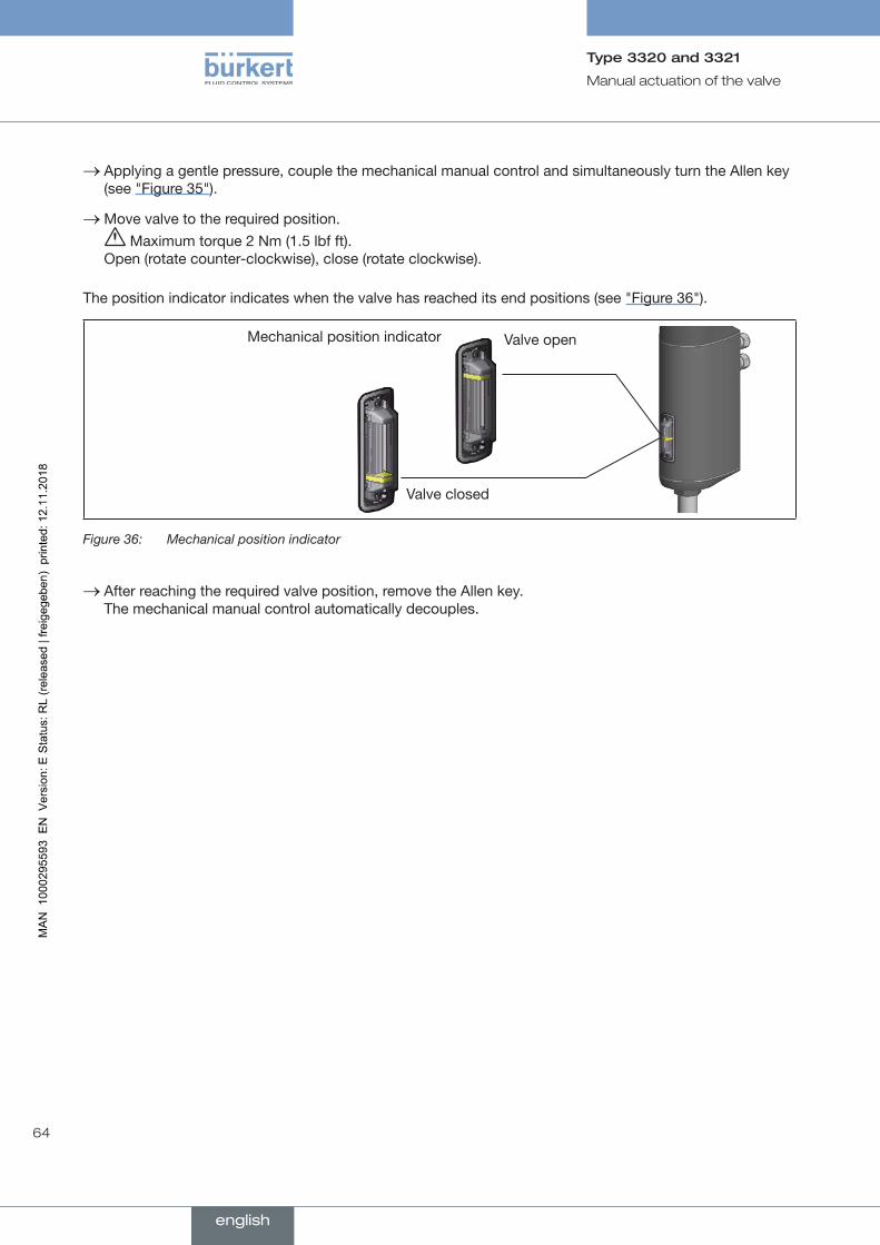
64
Manual actuation of the valve
Type 3320 and 3321
→ Applying a gentle pressure, couple the mechanical manual control and simultaneously turn the Allen key (see "Figure 35").
→Move valve to the required position. Maximum torque 2 Nm (1.5 lbf ft).
Open (rotate counter-clockwise), close (rotate clockwise).
The position indicator indicates when the valve has reached its end positions (see "Figure 36").
Valve open
Valve closed
Mechanical position indicator
Figure 36: Mechanical position indicator
→ After reaching the required valve position, remove the Allen key. The mechanical manual control automatically decouples.
english

65
Operating structure / factory setting
Type 3320 and 3321
16 OPERATING STRUCTURE / FACTORY SETTINGThe factory presets are highlighted in blue to the right of the menu in the operating structure.
Examples: / Menu options activated or selected at the factory
/ Menu options not activated or selected at the factory
2 %, 10 sec, ... Values set at the factory
16.1 Operating structure of the configuration area
State of health
SAFEPOS ONDIP.SWITCH
NC / NO
Not used
MANUAL MODE
ENERGY-PACK 1) FUNCTION On | Off
FUNCTION Immediate control
Control if ready
On
ADD.FUNCTION
X.LIMIT
X.TIME
X.LIMIT
Maximum
Opening time
X.TIME
Closing time
Activatable auxiliary functions
Activatedauxiliaryfunctions
Position controller
PARAMETER
Figure 37: Operating structure - 1-a, Configuration area position controller
1) Only available for devices with SAFEPOS energy pack (optional).
english

66
Operating structure / factory setting
Type 3320 and 3321
Position controller
MAINTENANCE
CALIBRATION X.TUNE
Figure 38: Operating structure - 1-b, Maintenance position controller
Position controller
DIAGNOSTICS
SYSTEM.VALUES
ENERGY-PACK
USER.DIAGNOSIS
Error
Acknowledge
Logbook
NAMUR-Type
POS.MONITOR
SERVICE.TIME
SERVICE.TIME
Out of Specification
TRAVEL.ACCU
TRAVEL.ACCU
CYCLE.COUNTER
CYCLE.COUNTER
POS.MONITOR
POS.MONITOR
Operation time
State of health
MSG.CONFIG
Travel accumulator
NAMUR-State
Direction change
Device temperature
Highest temperature
Lowest temperature
HISTOGRAM.POS
HISTOGRAM.SPAN
HISTOGRAM.DTEMP
ADD.DIAGNOSE
Figure 39: Operating structure - 1-c, Diagnostics position controller
english
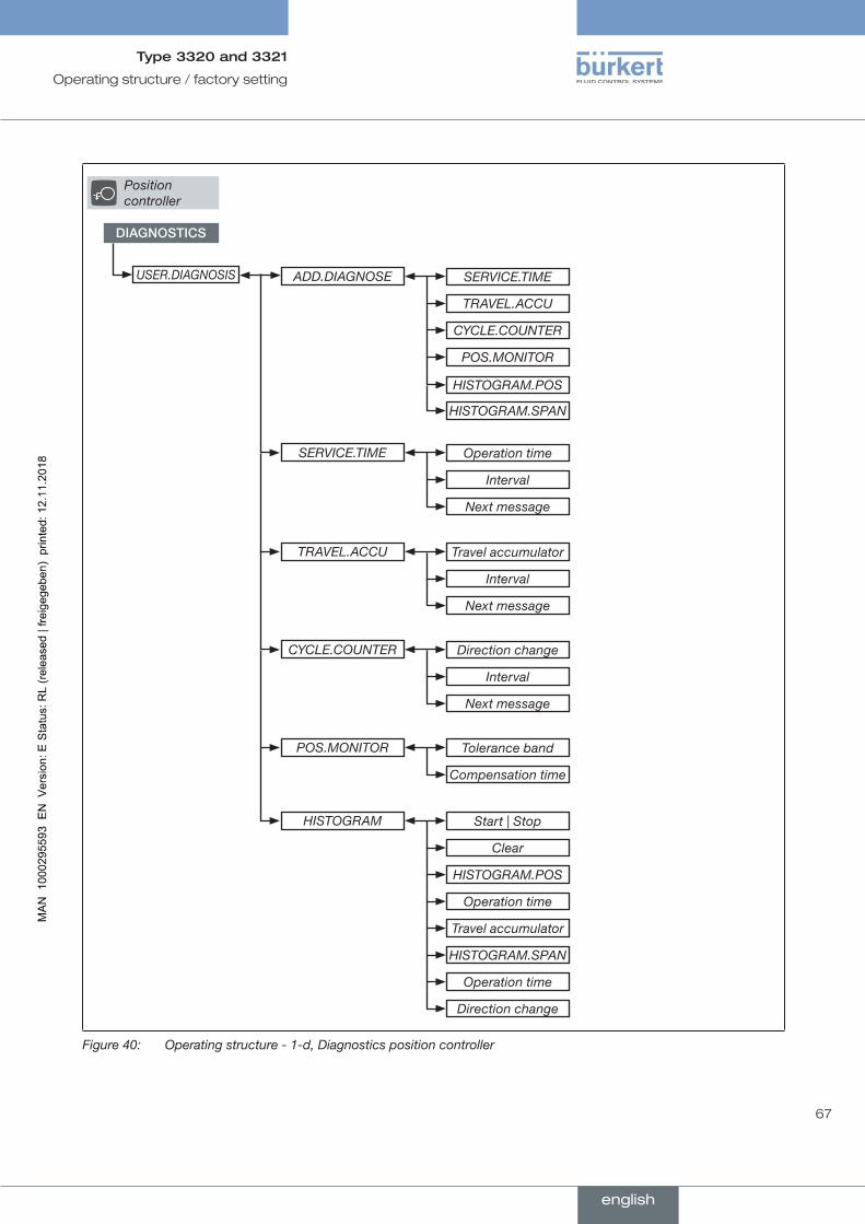
67
Operating structure / factory setting
Type 3320 and 3321
Position controller
DIAGNOSTICS
USER.DIAGNOSIS SERVICE.TIME
Operation time
Travel accumulator
Direction change
Tolerance band
Start | Stop
TRAVEL.ACCU
Interval
Interval
Interval
Compensation time
Clear
HISTOGRAM.POS
Operation time
Travel accumulator
HISTOGRAM.SPAN
Operation time
Direction change
CYCLE.COUNTER
Next message
Next message
Next message
POS.MONITOR
HISTOGRAM.POS
HISTOGRAM.SPAN
ADD.DIAGNOSE
SERVICE.TIME
TRAVEL.ACCU
CYCLE.COUNTER
POS.MONITOR
HISTOGRAM
Figure 40: Operating structure - 1-d, Diagnostics position controller
english
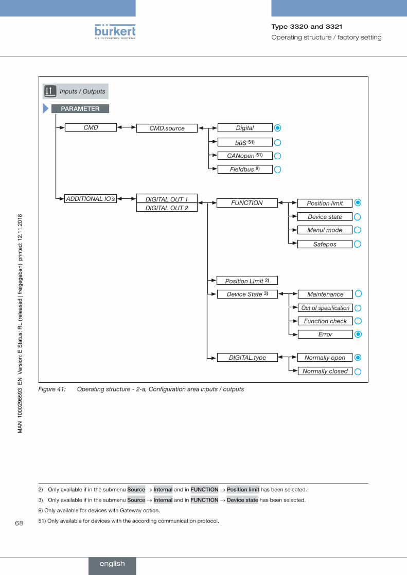
68
Operating structure / factory setting
Type 3320 and 3321
Inputs / Outputs
PARAMETER
CMD
ADDITIONAL IO´s
CMD.source Digital
büS 51)
CANopen 51)
Fieldbus 9)
DIGITAL OUT 1 DIGITAL OUT 2
FUNCTION
Device State 3)
Position limit
Maintenance
Device state
Out of specification
Manul mode
Function check
Error
Safepos
Position Limit 2)
DIGITAL.type Normally open
Normally closed
Figure 41: Operating structure - 2-a, Configuration area inputs / outputs
2) Only available if in the submenu Source → Internal and in FUNCTION → Positionlimit has been selected.
3) Only available if in the submenu Source → Internal and in FUNCTION → Devicestate has been selected.
9) Only available for devices with Gateway option.
51) Only available for devices with the according communication protocol.
english
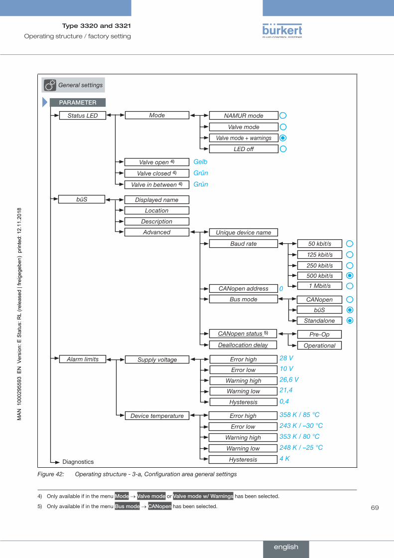
69
Operating structure / factory setting
Type 3320 and 3321
Status LED Mode NAMUR mode
Valve mode
LED off
Diagnostics
Valve mode + warnings
büS Displayed name
Valve open 4)
Location
Valve closed 4)
Valve in between 4)
Description
Advanced
CANopen status 5)
Deallocation delay
0
Unique device name
Pre-Op
Baud rate
Operational
CANopen address
Bus mode
50 kbit/s
250 kbit/s
125 kbit/s
500 kbit/s
1 Mbit/s
CANopen
büS
Standalone
Alarm limits Supply voltage
Device temperature
Error high
Error low
Warning high
Warning low
Hysteresis
21,4
0,4
26,6 V
10 V
28 V
Error high
Error low
Warning high
Warning low
Hysteresis
248 K / –25 °C
4 K
353 K / 80 °C
243 K / –30 °C
358 K / 85 °C
Grün
Grün
Gelb
PARAMETER
General settings
Figure 42: Operating structure - 3-a, Configuration area general settings
4) Only available if in the menu Mode → Valvemode or Valvemodew/Warnings has been selected.
5) Only available if in the menu Busmode → CANopen has been selected.
english
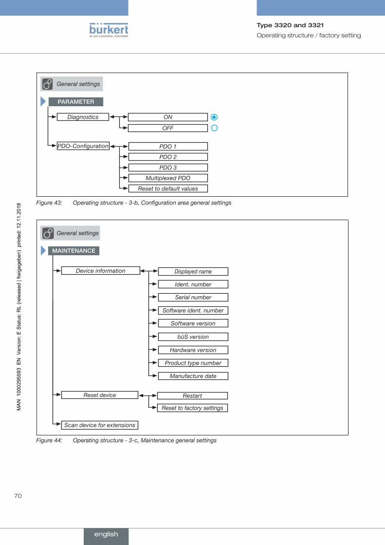
70
Operating structure / factory setting
Type 3320 and 3321
PARAMETER
Diagnostics ON
OFF
PDO-Configuration PDO 1
PDO 2
PDO 3
Multiplexed PDO
Reset to default values
General settings
Figure 43: Operating structure - 3-b, Configuration area general settings
General settings
MAINTENANCE
Restart
Reset to factory settings
Reset device
Scan device for extensions
Displayed name
Ident. number
Serial number
Software ident. number
Software version
Device information
büS version
Hardware version
Product type number
Manufacture date
Figure 44: Operating structure - 3-c, Maintenance general settings
english
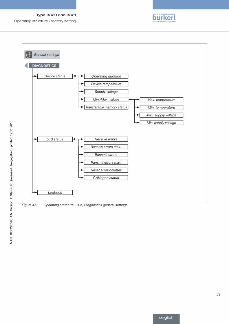
71
Operating structure / factory setting
Type 3320 and 3321
General settings
DIAGNOSTICS
Device status Operating duration
Device temperature
Supply voltage
Transferable memory status
büS status
Max. temperature
Min. temperature
Max. supply voltage
Min. supply voltage
Receive errors
Receive errors max.
Transmit errors
Transmit errors max.
Reset error counter
CANopen status
Min./Max. values
Logbook
Figure 45: Operating structure - 3-d, Diagnostics general settings
english
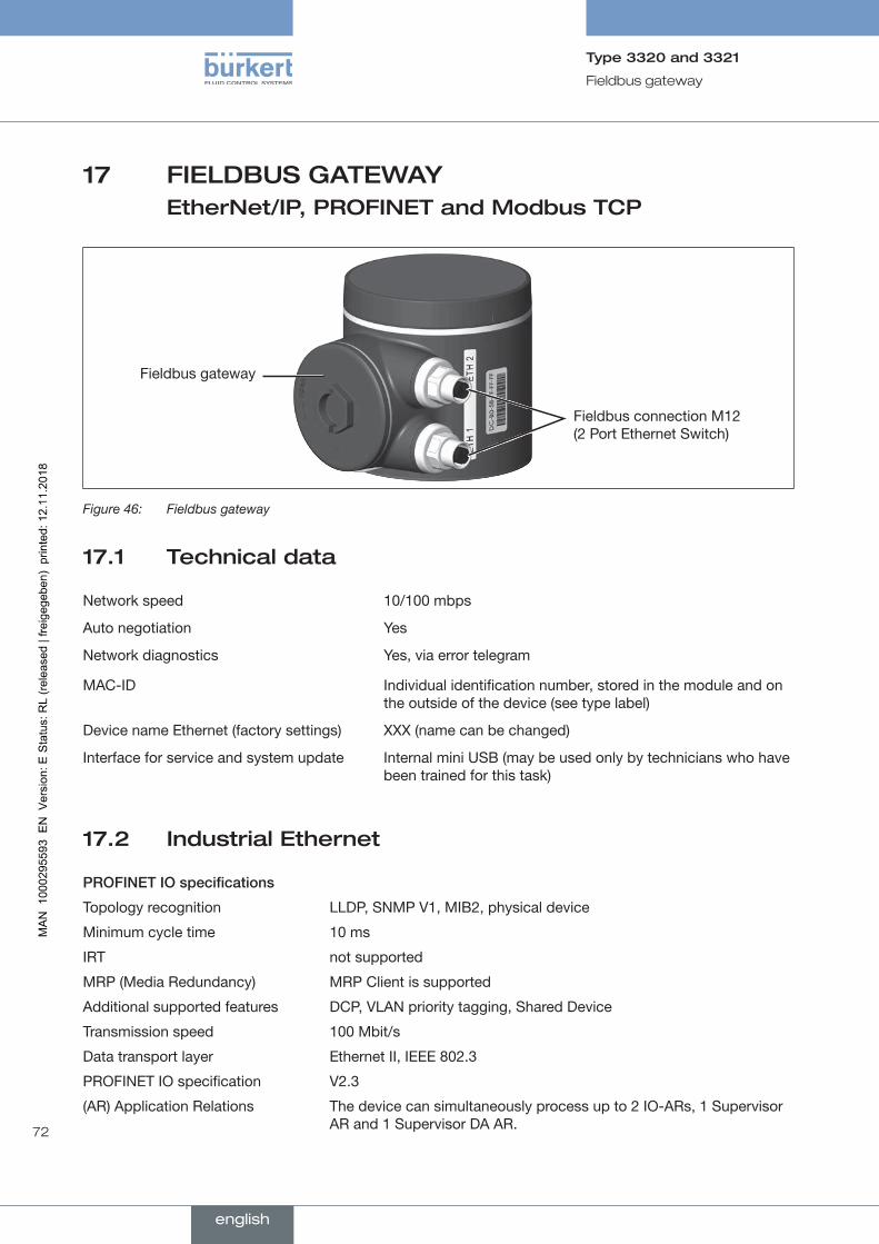
72
Fieldbus gateway
Type 3320 and 3321
17 FIELDBUS GATEWAY EtherNet/IP, PROFINET and Modbus TCP
Fieldbus gateway
Fieldbus connection M12 (2 Port Ethernet Switch)
Figure 46: Fieldbus gateway
17.1 Technical data
Network speed 10/100 mbps
Auto negotiation Yes
Network diagnostics Yes, via error telegram
MAC-ID Individual identification number, stored in the module and on the outside of the device (see type label)
Device name Ethernet (factory settings) XXX (name can be changed)
Interface for service and system update Internal mini USB (may be used only by technicians who have been trained for this task)
17.2 Industrial Ethernet
PROFINETIOspecifications
Topology recognition LLDP, SNMP V1, MIB2, physical device
Minimum cycle time 10 ms
IRT not supported
MRP (Media Redundancy) MRP Client is supported
Additional supported features DCP, VLAN priority tagging, Shared Device
Transmission speed 100 Mbit/s
Data transport layer Ethernet II, IEEE 802.3
PROFINET IO specification V2.3
(AR) Application Relations The device can simultaneously process up to 2 IO-ARs, 1 Supervisor AR and 1 Supervisor DA AR.
english

73
Fieldbus gateway
Type 3320 and 3321
EtherNet/IPspecifications
Predefined standard objects Identity Object (0x01)
Message Router Object (0x02)
Assembly Object (0x04)
Connection Manager (0x06)
DLR Object (0x47)
QoS Object (0x48)
TCP/IP Interface Object (0xF5)
Ethernet Link Object (0xF6)
DHCP supported
BOOTP supported
Transmission speed 10 and 100 Mbit/s
Duplex transmission Half Duplex, full Duplex, autonegotiation
MDI modes MDI, MDI-X, Auto-MDIX
Data transport layer Ethernet II, IEEE 802.3
Address Conflict Detection (ACD) supported
DLR (ring topology) supported
Integrated switch supported
CIP Reset services Identity Object Reset Service of Type 0 and 1
Modbus TCP specifications
Modbus Function Codes 1, 2, 3, 4, 6, 15, 16, 23
Mode Message Mode: Server
Transmission speed 10 and 100 Mbit/s
Data transport layer Ethernet II, IEEE 802.3
17.3 Electrical connection
The fieldbus gateway is connected with a circular plug-in connector M12, 4-pole.
43
12
Pin 1 Transmit +
Pin 2 Receive +
Pin 3 Transmit –
Pin 4 Receive –
Table 19: Electrical assignment
english
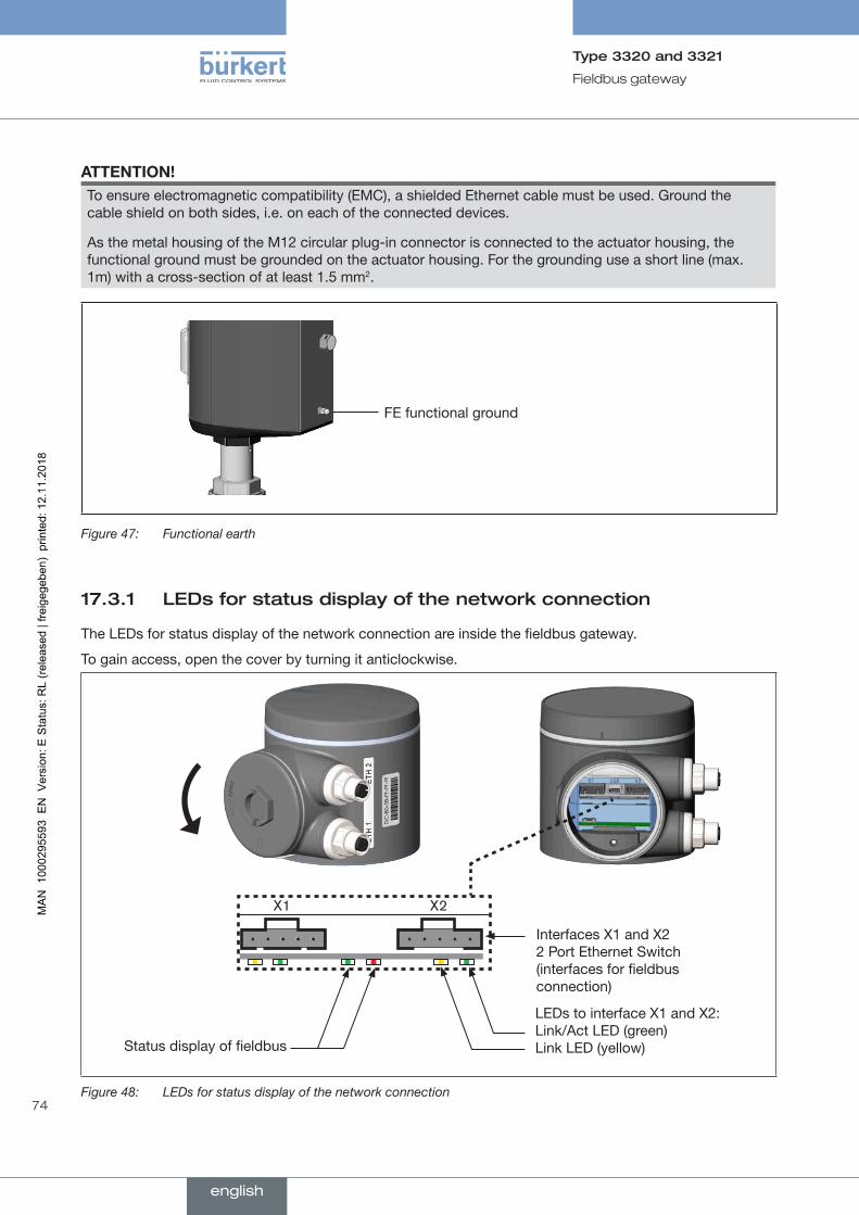
74
Fieldbus gateway
Type 3320 and 3321
ATTENTION!To ensure electromagnetic compatibility (EMC), a shielded Ethernet cable must be used. Ground the cable shield on both sides, i.e. on each of the connected devices.
As the metal housing of the M12 circular plug-in connector is connected to the actuator housing, the functional ground must be grounded on the actuator housing. For the grounding use a short line (max. 1m) with a cross-section of at least 1.5 mm2.
FE functional ground
Figure 47: Functional earth
17.3.1 LEDs for status display of the network connection
The LEDs for status display of the network connection are inside the fieldbus gateway.
To gain access, open the cover by turning it anticlockwise.
Interfaces X1 and X2 2 Port Ethernet Switch (interfaces for fieldbus connection)
LEDs to interface X1 and X2: Link/Act LED (green) Link LED (yellow)Status display of fieldbus
Figure 48: LEDs for status display of the network connection
english
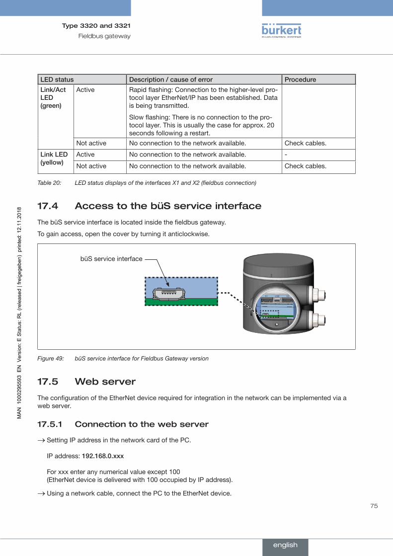
75
Fieldbus gateway
Type 3320 and 3321
LEDstatus Description/causeoferror Procedure
Link/ActLED (green)
Active Rapid flashing: Connection to the higher-level pro-tocol layer EtherNet/IP has been established. Data is being transmitted.
Slow flashing: There is no connection to the pro-tocol layer. This is usually the case for approx. 20 seconds following a restart.
Not active No connection to the network available. Check cables.
LinkLED (yellow)
Active No connection to the network available. -
Not active No connection to the network available. Check cables.
Table 20: LED status displays of the interfaces X1 and X2 (fieldbus connection)
17.4 Access to the büS service interface
The büS service interface is located inside the fieldbus gateway.
To gain access, open the cover by turning it anticlockwise.
büS service interface
Figure 49: büS service interface for Fieldbus Gateway version
17.5 Web server
The configuration of the EtherNet device required for integration in the network can be implemented via a web server.
17.5.1 Connection to the web server
→ Setting IP address in the network card of the PC. IP address: 192.168.0.xxx For xxx enter any numerical value except 100 (EtherNet device is delivered with 100 occupied by IP address).
→ Using a network cable, connect the PC to the EtherNet device.
english

76
Fieldbus gateway
Type 3320 and 3321
17.5.2 Access to the web server
Bürkert S/N: 99
IndustrialCommunicationProtocol PROFINET
Communication status Waitforestablishingcommunication
DNS compatible name
MAC address 00:50:C2:C7:E0:01
Static IP address 192.168.0.100
Network mask 255.255.255.0
Default gateway 192.168.0.1
Temporary IP address 192.168.0.100
IP settings None
Figure 50: Access to the web server via the Default IP
With EtherNet/IP, it is also possible to set DHCP or BOOTP (NOT standard). The IP address is acquired from a DHCP server.
→ Open an Internet browser.
→ Input Default IP 192.168.0.100. (For Ethernet/IP devices the IP address is assigned via a DHCP server. If no assignment occurs within 1 minute via DHCP, the device uses the Default IP 192.168.0.100.)
The software for configuration of the EtherNet device is now available on the PC.
Configurationofseveraldevices:
All devices are delivered with the same IP address (192.168.0.100). To ensure that the device can be identified for the configuration, the network may contain only 1 device which has not yet been configured.
▶ Connect the devices (EtherNet device) in succession, individually to the network and configure.
english

77
Fieldbus gateway
Type 3320 and 3321
17.5.3 Configuring EtherNet device
Logging into the system:
→ Input user name and password. Username: admin Password: admin
Bürkert S/N: 99
Userlogin
User name admin
User password admin x
Login
Figure 51: Logging into the system
english
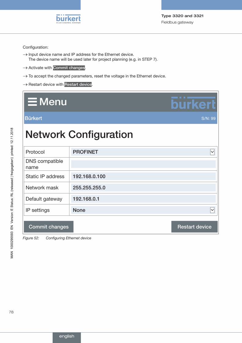
78
Fieldbus gateway
Type 3320 and 3321
Configuration:
→ Input device name and IP address for the Ethernet device. The device name will be used later for project planning (e.g. in STEP 7).
→ Activate with Commitchanges.
→ To accept the changed parameters, reset the voltage in the Ethernet device.
→ Restart device with Restartdevice.
Bürkert S/N: 99
NetworkConfiguration
Commitchanges Restartdevice
Protocol PROFINET
DNS compatible name
Static IP address 192.168.0.100
Network mask 255.255.255.0
Default gateway 192.168.0.1
IP settings None
Figure 52: Configuring Ethernet device
english
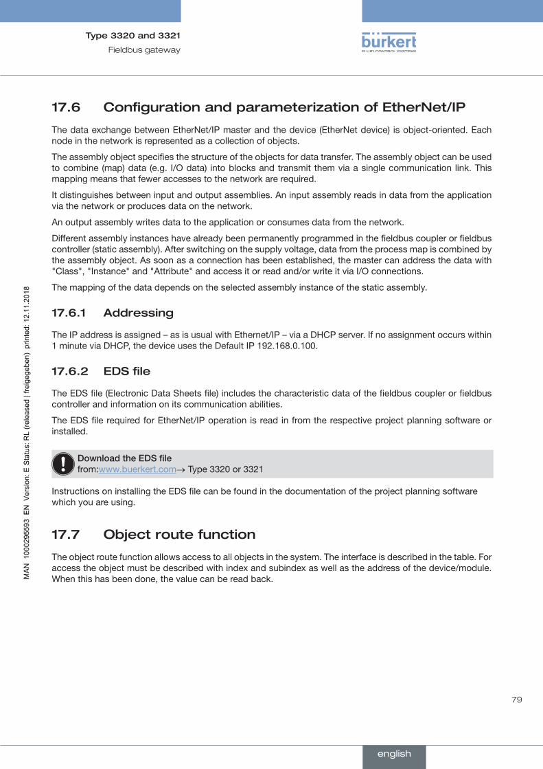
79
Fieldbus gateway
Type 3320 and 3321
17.6 Configuration and parameterization of EtherNet/IP
The data exchange between EtherNet/IP master and the device (EtherNet device) is object-oriented. Each node in the network is represented as a collection of objects.
The assembly object specifies the structure of the objects for data transfer. The assembly object can be used to combine (map) data (e.g. I/O data) into blocks and transmit them via a single communication link. This mapping means that fewer accesses to the network are required.
It distinguishes between input and output assemblies. An input assembly reads in data from the application via the network or produces data on the network.
An output assembly writes data to the application or consumes data from the network.
Different assembly instances have already been permanently programmed in the fieldbus coupler or fieldbus controller (static assembly). After switching on the supply voltage, data from the process map is combined by the assembly object. As soon as a connection has been established, the master can address the data with "Class", "Instance" and "Attribute" and access it or read and/or write it via I/O connections.
The mapping of the data depends on the selected assembly instance of the static assembly.
17.6.1 Addressing
The IP address is assigned – as is usual with Ethernet/IP – via a DHCP server. If no assignment occurs within 1 minute via DHCP, the device uses the Default IP 192.168.0.100.
17.6.2 EDS file
The EDS file (Electronic Data Sheets file) includes the characteristic data of the fieldbus coupler or fieldbus controller and information on its communication abilities.
The EDS file required for EtherNet/IP operation is read in from the respective project planning software or installed.
DownloadtheEDSfile from:www.buerkert.com→ Type 3320 or 3321
Instructions on installing the EDS file can be found in the documentation of the project planning software which you are using.
17.7 Object route function
The object route function allows access to all objects in the system. The interface is described in the table. For access the object must be described with index and subindex as well as the address of the device/module. When this has been done, the value can be read back.
english

80
Fieldbus gateway
Type 3320 and 3321
Name Description
Accesstype ProfiNet EtherNet/IP ModbusTCP
Slo
t
Sub
slot
Inde
x
Cla
ss
Inst
ance
Att
ribut
es
Func
tion
code
(FC
)
Sta
rt
addr
ess
Num
ber
of
elem
ents
Address (UNIT32) Specified address (node D) and object
→ Observe byte sequence: Little Endian.
RW 0 1 1 0xc7 1 1 FC16 1000 2
• Byte 3: Device address (NODE ID)
• Byte 2: Sub index
• Byte 1: Index (low byte)
• Byte 0: Index (high byte)Data length (UNIT32)
ReservedRW 0 1 2 c7 2 1 FC16 1002 2
Value in UNIT32
(UNIT32) Value of the required object
RO 0 1 3 c7 3 1 FC16 1004 2
Value as string (C_String) Value if greater than 4 bytes
RO 0 1 4 c7 4 1 FC16 1006 10
Result (UNIT32) 0x00000000 finished 0xFFFFFFFF running
RO 0 1 5 c7 5 1 FC4 1016 2
Start/Cancel (UNIT8) Start or cancel the function
RW 0 1 6 c7 6 1 FC6 1018 2
Table 21: Object route function
17.7.1 Examples of use
1. Protocol-specific access to the object route function:
ProfiNet
Slot Subslot Index0 1 1
EtherNet/IP
Class Instance Attributes0xc7 0x01 0x03
ModbusTCP
Function code (FC) Start address Number of elementsFC16 1000 2
Table 22: Example of use 1
Example of reading the device status object (0x2004 sub 0x01) from the device with address 0x28:
→ 0x28012004
english
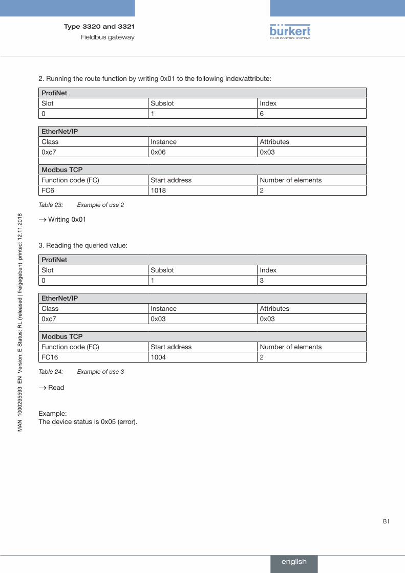
81
Fieldbus gateway
Type 3320 and 3321
2. Running the route function by writing 0x01 to the following index/attribute:
ProfiNet
Slot Subslot Index0 1 6
EtherNet/IP
Class Instance Attributes0xc7 0x06 0x03
ModbusTCP
Function code (FC) Start address Number of elementsFC6 1018 2
Table 23: Example of use 2
→Writing 0x01
3. Reading the queried value:
ProfiNet
Slot Subslot Index0 1 3
EtherNet/IP
Class Instance Attributes0xc7 0x03 0x03
ModbusTCP
Function code (FC) Start address Number of elementsFC16 1004 2
Table 24: Example of use 3
→ Read
Example: The device status is 0x05 (error).
english

82
Fieldbus gateway
Type 3320 and 3321
17.8 Objects
The following objects allow additional control and monitoring.
17.8.1 Device status NAMUR NE 107
Name Description Accesstype
Device state
NAMUR NE 107
Corresponds to the device status of type 3323, 3324 and 3325
RO
Bit 7 Bit 6 Bit 5 Bit 4 Bit 3 Bit 2 Bit 1 Bit 0
reserved reserved NAMUR mode: NAMUR status:
0 – Automatic mode 0 – Normal1 – Manual mode 1 – Diagnostics active2 – Flashing 2 – Maintenance required
3 – Device out of specification4 – Warning5 – Error
Table 25: Device status NAMUR NE 107
17.8.2 büS control object
Name Description Accesstype
Control mode* Byte 0: defines the device behavior and communication with the con-nected devices. It can therefore be defined when the device starts trans-ferring process data.
Byte 1: defines the device behavior if a device fails.
RW
Control word** Byte 0: Address of the device to be controlled.
Byte 1: Node (device) management according to CANopen specification.
RW
* Byte1 Byte0
0: reserved 0: Automatic mode (büS standard)
1: Do not cancel allocation to missing device
1: Input for operation with COM
2: Input for operation with PLCByte3 Byte2
Reserved Reserved
** Byte1 Byte0
0x81: Reset node (device restart) 0xFF: All devices
Byte3 Byte2
Reserved Reserved
Table 26: büS control object
english

83
Maintenance, troubleshooting
Type 3320 and 3321
18 MAINTENANCE, TROUBLESHOOTING
18.1 Safety instructions
DANGER!
Riskofinjuryfromhighpressureinthesystemordevice.
▶ Before working on the system or device, switch off the pressure. Vent or drain lines.
Riskofinjuryduetoelectricshock.
▶ Before working on the system or device, switch off the power supply. Secure against reactivation.
▶ Observe applicable accident prevention and safety regulations for electrical equipment.
WARNING!
Riskofinjuryfromimpropermaintenancework.
▶ Maintenance may be carried out only by trained technicians and with the appropriate tools.
▶ Secure system against unintentional activation.
▶ Following maintenance, ensure a controlled restart.
18.2 Maintenance
Maintenance work is described in the separate service manual. Find these instructions on our homepage at: www.buerkert.com → Type 3320, 3321.
18.2.1 Actuator
Provided the valve is operated according to these operating instructions, the electromotive actuator is maintenance-free.
18.2.2 Wearing parts of the valve
Parts which are subject to natural wear:
• Seals
• Swivel plate
• Valve seat
→ If a wearing part is leaking, replace the particular wearing part with an appropriate spare part. (Spare parts sets and installation tools see chapter "20.2 Spare parts".
How to change wearing parts is described in the separate service manual. You can find these instructions on our homepage at: www.burkert.com → Type 3320, 3321.
english
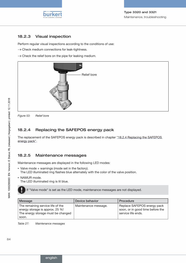
84
Maintenance, troubleshooting
Type 3320 and 3321
18.2.3 Visual inspection
Perform regular visual inspections according to the conditions of use:
→ Check medium connections for leak-tightness.
→ Check the relief bore on the pipe for leaking medium.
Relief bore
Figure 53: Relief bore
18.2.4 Replacing the SAFEPOS energy pack
The replacement of the SAFEPOS energy pack is described in chapter "18.2.4 Replacing the SAFEPOS energy pack".
18.2.5 Maintenance messages
Maintenance messages are displayed in the following LED modes:
• Valve mode + warnings (mode set in the factory). The LED illuminated ring flashes blue alternately with the color of the valve position.
• NAMUR mode. The LED illuminated ring is lit blue.
If "Valve mode" is set as the LED mode, maintenance messages are not displayed.
Message Devicebehavior Procedure
The remaining service life of the energy storage is approx. 25 %! The energy storage must be changed soon.
Maintenance message. Replace SAFEPOS energy pack soon, or in good time before the service life ends.
Table 27: Maintenance messages
english
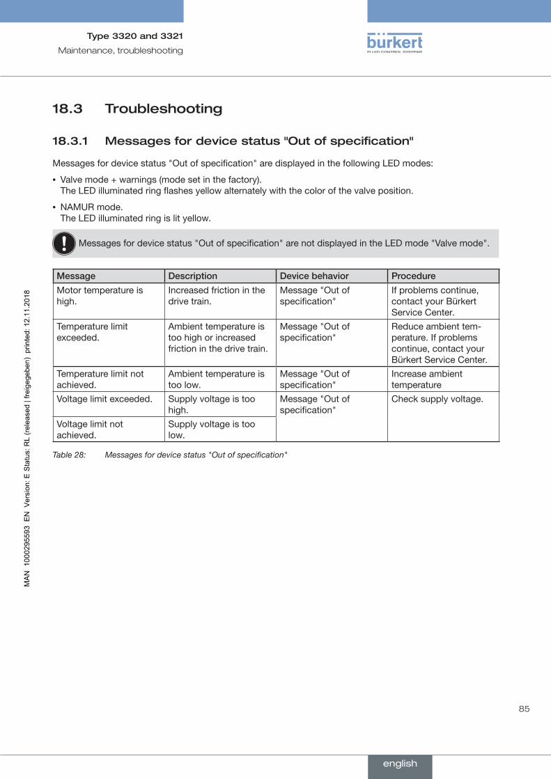
85
Maintenance, troubleshooting
Type 3320 and 3321
18.3 Troubleshooting
18.3.1 Messages for device status "Out of specification"
Messages for device status "Out of specification" are displayed in the following LED modes:
• Valve mode + warnings (mode set in the factory). The LED illuminated ring flashes yellow alternately with the color of the valve position.
• NAMUR mode. The LED illuminated ring is lit yellow.
Messages for device status "Out of specification" are not displayed in the LED mode "Valve mode".
Message Description Devicebehavior Procedure
Motor temperature is high.
Increased friction in the drive train.
Message "Out of specification"
If problems continue, contact your Bürkert Service Center.
Temperature limit exceeded.
Ambient temperature is too high or increased friction in the drive train.
Message "Out of specification"
Reduce ambient tem-perature. If problems continue, contact your Bürkert Service Center.
Temperature limit not achieved.
Ambient temperature is too low.
Message "Out of specification"
Increase ambient temperature
Voltage limit exceeded. Supply voltage is too high.
Message "Out of specification"
Check supply voltage.
Voltage limit not achieved.
Supply voltage is too low.
Table 28: Messages for device status "Out of specification"
english
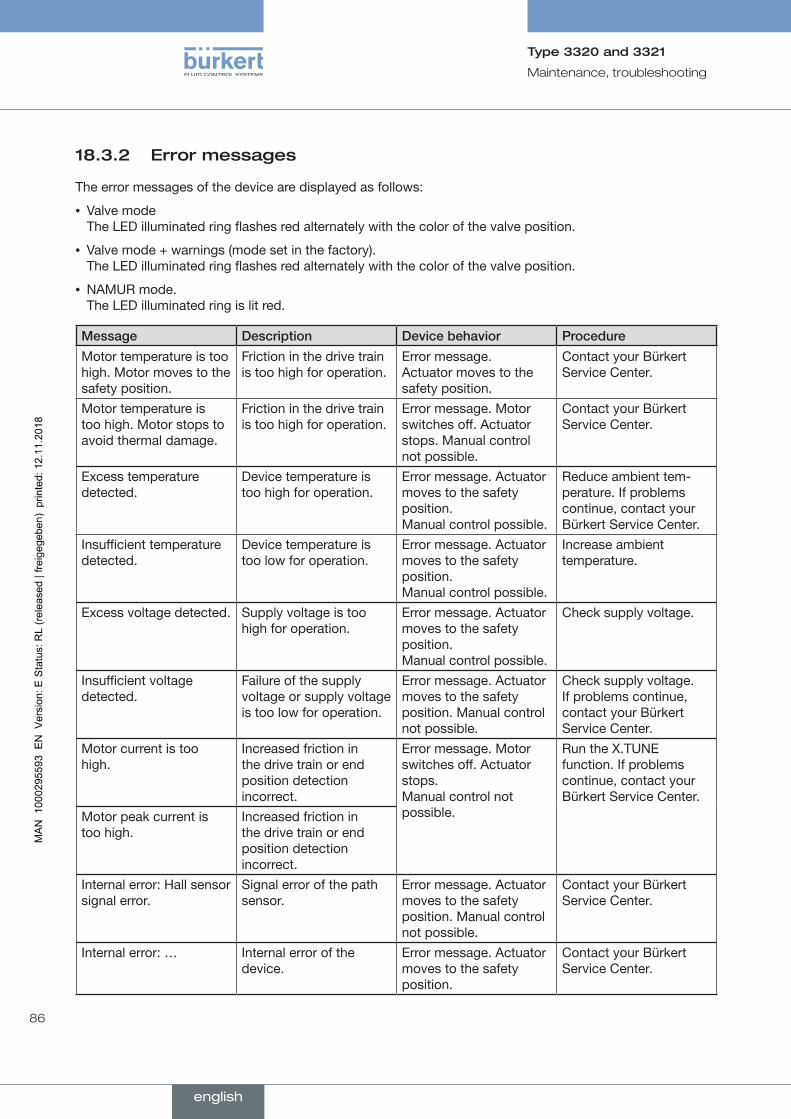
86
Maintenance, troubleshooting
Type 3320 and 3321
18.3.2 Error messages
The error messages of the device are displayed as follows:
• Valve mode The LED illuminated ring flashes red alternately with the color of the valve position.
• Valve mode + warnings (mode set in the factory). The LED illuminated ring flashes red alternately with the color of the valve position.
• NAMUR mode. The LED illuminated ring is lit red.
Message Description Devicebehavior Procedure
Motor temperature is too high. Motor moves to the safety position.
Friction in the drive train is too high for operation.
Error message. Actuator moves to the safety position.
Contact your Bürkert Service Center.
Motor temperature is too high. Motor stops to avoid thermal damage.
Friction in the drive train is too high for operation.
Error message. Motor switches off. Actuator stops. Manual control not possible.
Contact your Bürkert Service Center.
Excess temperature detected.
Device temperature is too high for operation.
Error message. Actuator moves to the safety position. Manual control possible.
Reduce ambient tem-perature. If problems continue, contact your Bürkert Service Center.
Insufficient temperature detected.
Device temperature is too low for operation.
Error message. Actuator moves to the safety position. Manual control possible.
Increase ambient temperature.
Excess voltage detected. Supply voltage is too high for operation.
Error message. Actuator moves to the safety position. Manual control possible.
Check supply voltage.
Insufficient voltage detected.
Failure of the supply voltage or supply voltage is too low for operation.
Error message. Actuator moves to the safety position. Manual control not possible.
Check supply voltage. If problems continue, contact your Bürkert Service Center.
Motor current is too high.
Increased friction in the drive train or end position detection incorrect.
Error message. Motor switches off. Actuator stops. Manual control not possible.
Run the X.TUNE function. If problems continue, contact your Bürkert Service Center.
Motor peak current is too high.
Increased friction in the drive train or end position detection incorrect.
Internal error: Hall sensor signal error.
Signal error of the path sensor.
Error message. Actuator moves to the safety position. Manual control not possible.
Contact your Bürkert Service Center.
Internal error: … Internal error of the device.
Error message. Actuator moves to the safety position.
Contact your Bürkert Service Center.
english
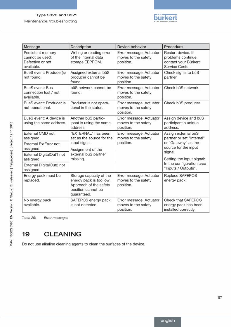
87
Maintenance, troubleshooting
Type 3320 and 3321
Message Description Devicebehavior Procedure
Persistent memory cannot be used: Defective or not available.
Writing or reading error of the internal data storage EEPROM.
Error message. Actuator moves to the safety position.
Restart device. If problems continue, contact your Bürkert Service Center.
BueS event: Producer(s) not found.
Assigned external büS producer cannot be found.
Error message. Actuator moves to the safety position.
Check signal to büS partner.
BueS event: Bus connection lost / not available.
büS network cannot be found.
Error message. Actuator moves to the safety position.
Check büS network.
BueS event: Producer is not operational.
Producer is not opera-tional in the status.
Error message. Actuator moves to the safety position.
Check büS producer.
BueS event: A device is using the same address.
Another büS partic-ipant is using the same address.
Error message. Actuator moves to the safety position.
Assign device and büS participant a unique address.
External CMD not assigned.
"EXTERNAL" has been set as the source for the input signal.
Assignment of the external büS partner missing.
Error message. Actuator moves to the safety position.
Assign external büS partner or set "Internal" or "Gateway" as the source for the input signal.
Setting the input signal: In the configuration area "Inputs / Outputs".
External ExtError not assigned.External DigitalOut1 not assigned.External DigitalOut2 not assigned.Energy pack must be replaced.
Storage capacity of the energy pack is too low. Approach of the safety position cannot be guaranteed.
Error message. Actuator moves to the safety position.
Replace SAFEPOS energy pack.
No energy pack available.
SAFEPOS energy pack is not detected.
Error message. Actuator moves to the safety position.
Check that SAFEPOS energy pack has been installed correctly.
Table 29: Error messages
19 CLEANINGDo not use alkaline cleaning agents to clean the surfaces of the device.
english
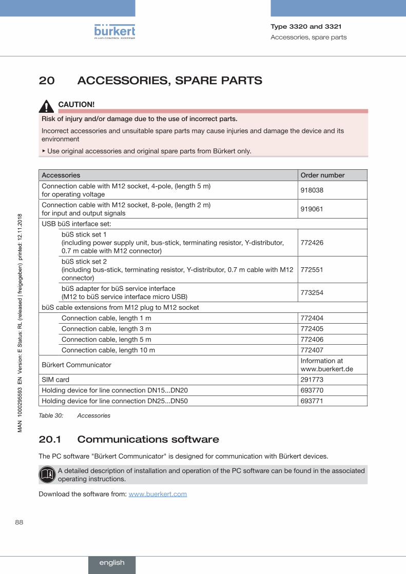
88
Accessories, spare parts
Type 3320 and 3321
20 ACCESSORIES, SPARE PARTS
CAUTION!
Riskofinjuryand/ordamageduetotheuseofincorrectparts.
Incorrect accessories and unsuitable spare parts may cause injuries and damage the device and its environment
▶ Use original accessories and original spare parts from Bürkert only.
Accessories Ordernumber
Connection cable with M12 socket, 4-pole, (length 5 m) for operating voltage 918038
Connection cable with M12 socket, 8-pole, (length 2 m) for input and output signals 919061
USB büS interface set:
büS stick set 1 (including power supply unit, bus-stick, terminating resistor, Y-distributor, 0.7 m cable with M12 connector)
772426
büS stick set 2 (including bus-stick, terminating resistor, Y-distributor, 0.7 m cable with M12 connector)
772551
büS adapter for büS service interface (M12 to büS service interface micro USB) 773254
büS cable extensions from M12 plug to M12 socket
Connection cable, length 1 m 772404
Connection cable, length 3 m 772405
Connection cable, length 5 m 772406
Connection cable, length 10 m 772407
Bürkert Communicator Information at www.buerkert.de
SIM card 291773
Holding device for line connection DN15...DN20 693770
Holding device for line connection DN25...DN50 693771
Table 30: Accessories
20.1 Communications software
The PC software "Bürkert Communicator" is designed for communication with Bürkert devices.
A detailed description of installation and operation of the PC software can be found in the associated operating instructions.
Download the software from: www.buerkert.com
english

89
Accessories, spare parts
Type 3320 and 3321
20.1.1 USB interface
To communicate with the devices, the PC requires a USB interface and the USB büS interface set available as an accessory. (see "Table 30: Accessories").
20.2 Spare parts
20.2.1 Spare parts for valves of Types 3320 and 3321
SparepartsforTypes3320and3321 Ordernumber
SAFEPOS energy-pack 285834
Seal set for packing glandSpindle ø10 mm, DN15...DN40 309618
Spindle ø14 mm, DN50 309621
Table 31: Spare parts for Types 3320 and 3321
20.2.2 Spare parts for angle seat valve of Type 3320
SwivelplatesetforType3320
includes: swivel plate, dowel pin, graphite seal
DNOrdernumber
PEEK/steel PTFE/steel
13/15 On request 011134
20 On request 011171
25 On request 160737
32 On request 011208
40 On request 011209
50 On request 216431
Table 32: Swivel plate set for Type 3320
20.2.3 Spare parts for globe valve of Type 3321
SwivelplatesetforType3321
includes: swivel plate, dowel pin, graphite seal
DNOrdernumber
PEEK/steel PTFE/steel
13/15 On request 149606
20 On request 011171
25 On request 160737
32 On request 011208
40 On request 011209
50 On request 216431
Table 33: Swivel plate set for Type 3321
english
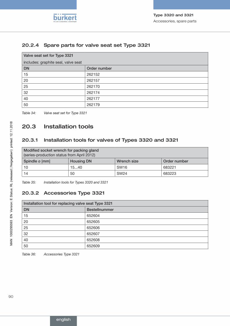
90
Accessories, spare parts
Type 3320 and 3321
20.2.4 Spare parts for valve seat set Type 3321
ValveseatsetforType3321
includes: graphite seal, valve seat
DN Ordernumber
15 262152
20 262157
25 262170
32 262174
40 262177
50 262179
Table 34: Valve seat set for Type 3321
20.3 Installation tools
20.3.1 Installation tools for valves of Types 3320 and 3321
Modifiedsocketwrenchforpackinggland (series-production status from April 2012)
Spindleø [mm] HousingDN Wrenchsize Ordernumber
10 15...40 SW16 683221
14 50 SW24 683223
Table 35: Installation tools for Types 3320 and 3321
20.3.2 Accessories Type 3321
InstallationtoolforreplacingvalveseatType3321
DN Bestellnummer
15 652604
20 652605
25 652606
32 652607
40 652608
50 652609
Table 36: Accessories Type 3321
english
91
Disassembly
Type 3320 and 3321
21 DISASSEMBLY
21.1 Safety instructions
DANGER!
Riskofinjuryfromhighpressureanddischargeofmedium.
If the device is under pressure when removed, there is a risk of injury due to sudden pressure release and discharge of medium.
▶ Before removing the device, switch off the pressure. Vent or drain the lines.
CAUTION!
Riskofinjuryduetoaheavydevice.
The device can fall down during transport or during installation and cause injuries.
▶ Transport, install and dismantle a heavy device with the help of another person.
▶ Use appropriate tools.
→ Disconnect the electrical connection.
→ Remove device.
english
92
Packaging, transport
Type 3320 and 3321
22 PACKAGING, TRANSPORT
CAUTION!
Riskofinjuryduetoaheavydevice.
The device can fall down during transport or during installation and cause injuries.
▶ Transport, install and dismantle a heavy device with the help of another person.
▶ Use appropriate tools.
ATTENTION!
Transportdamage.
Inadequately protected devices may be damaged during transportation.
• Protect the device against moisture and dirt in shock-resistant packaging during transportation.
• Prevent the temperature from exceeding or dropping below the permitted storage temperature.
23 STORAGE
ATTENTION!
Incorrectstoragemaydamagethedevice.
• Store the device in a dry and dust-free location.
• Storage temperature -40...+70 °C.
24 DISPOSAL
ATTENTION!
Damagetotheenvironmentcausedbypartscontaminatedwithmedia.
• Dispose of the device and packaging in an environmentally friendly manner.
• Observe applicable disposal and environmental regulations.
Observe the national waste disposal regulations.
english

www.burkert.com