type 10 - bellofram precision...
TRANSCRIPT
2 800.727.5646 • www.marshbellofram.com
Air R
eg
ula
tors
Features
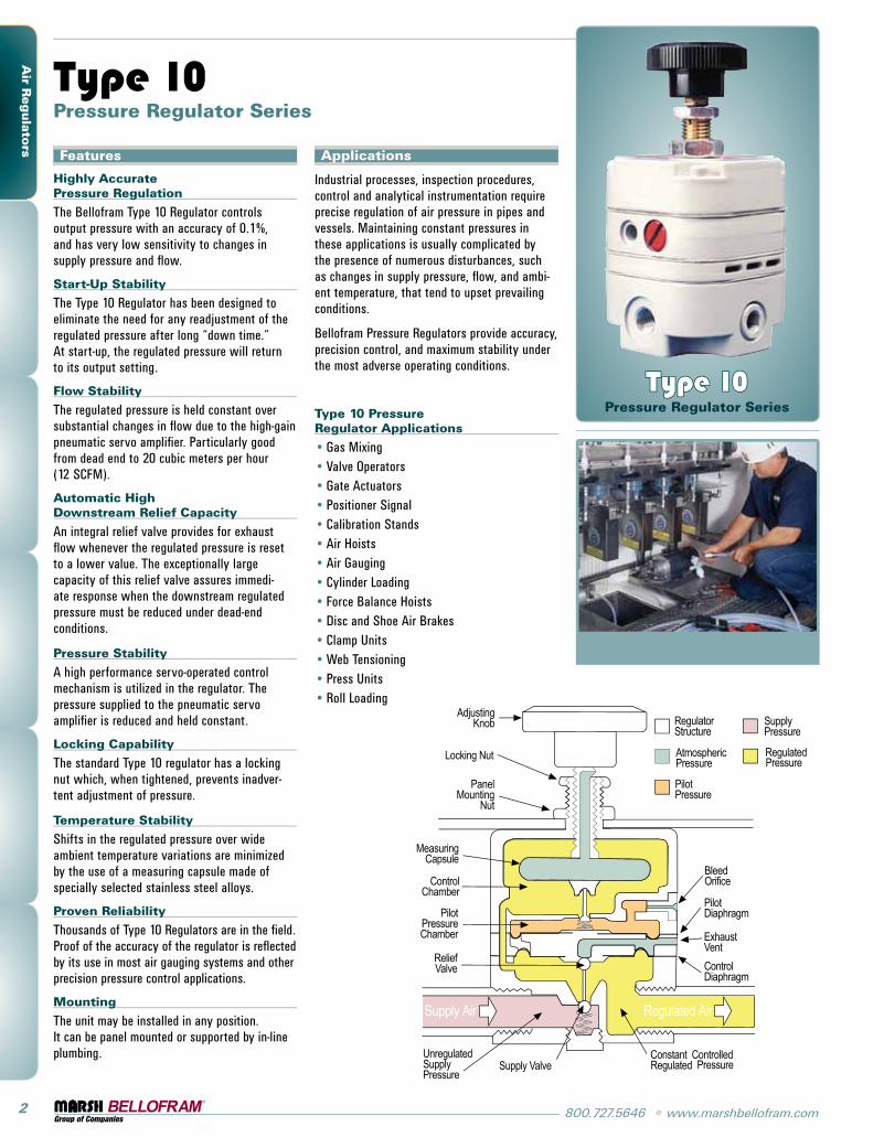
Highly Accurate Pressure Regulation
The Bellofram Type 10 Regulator controls output pressure with an accuracy of 0.1%, and has very low sensitivity to changes in supply pressure and flow.
Start-Up Stability
The Type 10 Regulator has been designed to eliminate the need for any readjustment of the regulated pressure after long “down time.” At start-up, the regulated pressure will return to its output setting.
Flow Stability
The regulated pressure is held constant over substantial changes in flow due to the high-gain pneumatic servo amplifier. Particularly good from dead end to 20 cubic meters per hour (12 SCFM).
Automatic High Downstream Relief Capacity
An integral relief valve provides for exhaust flow whenever the regulated pressure is reset to a lower value. The exceptionally large capacity of this relief valve assures immedi-ate response when the downstream regulated pressure must be reduced under dead-end conditions.
Pressure Stability
A high performance servo-operated control mechanism is utilized in the regulator. The pressure supplied to the pneumatic servo amplifier is reduced and held constant.
Locking Capability
The standard Type 10 regulator has a locking nut which, when tightened, prevents inadver-tent adjustment of pressure.
Temperature Stability
Shifts in the regulated pressure over wide ambient temperature variations are minimized by the use of a measuring capsule made of specially selected stainless steel alloys.
Proven Reliability
Thousands of Type 10 Regulators are in the field. Proof of the accuracy of the regulator is reflected by its use in most air gauging systems and other precision pressure control applications.
Mounting
The unit may be installed in any position. It can be panel mounted or supported by in-line plumbing.
Type 10 Pressure Regulator Series
Applications
Industrial processes, inspection procedures, control and analytical instrumentation require precise regulation of air pressure in pipes and vessels. Maintaining constant pressures in these applications is usually complicated by the presence of numerous disturbances, such as changes in supply pressure, flow, and ambi-ent temperature, that tend to upset prevailing conditions.
Bellofram Pressure Regulators provide accuracy, precision control, and maximum stability under the most adverse operating conditions.
Type 10 Pressure Regulator Applications
•Gas Mixing •Valve Operators•Gate Actuators •Positioner Signal •Calibration Stands •Air Hoists•Air Gauging •Cylinder Loading•Force Balance Hoists•Disc and Shoe Air Brakes•Clamp Units•Web Tensioning •Press Units•Roll Loading
Type 10 Pressure Regulator Series
www.marshbellofram.com • 800.727.5646 3
Air
Reg
ula
torsType 10PL
Plunger Operated Regulator
The basic Type 10 Regulator is offered with a choice of three port sizes and three output ranges.
Type 10HR & 10EXHR High Relief Regulators
Similar in proven accuracy and rugged construction to other Type 10 Regulators, these units provide extra fast “blowdown” for very rapid release of down stream pressure. The extra relief feature makes these regulators suitable for cylinder return stroke actuation, air hoists, and similar applications requiring fast exhaust.
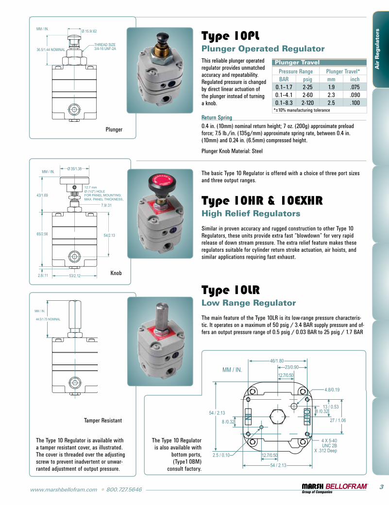
Type 10LR Low Range Regulator
The main feature of the Type 10LR is its low-range pressure characteris-tic. It operates on a maximum of 50 psig / 3.4 BAR supply pressure and of-fers an output pressure range of 0.5 psig / 0.03 BAR to 25 psig / 1.7 BAR
Plunger Travel Pressure Range Plunger Travel*BAR psig mm inch
0.1–1.7 2-25 1.9 .0750.1–4.1 2-60 2.3 .0900.1–8.3 2-120 2.5 .100
*±10% manufacturing tolerance
This reliable plunger operated regulator provides unmatched accuracy and repeatability. Regulated pressure is changed by direct linear actuation of the plunger instead of turning a knob.
Return Spring0.4 in. (10mm) nominal return height; 7 oz. (200g) approximate preload force; 7.5 lb./in. (135g/mm) approximate spring rate, between 0.4 in. (10mm) and 0.24 in. (6.5mm) compressed height.
Plunger Knob Material: Steel
The Type 10 Regulator is available with a tamper resistant cover, as illustrated. The cover is threaded over the adjusting screw to prevent inadvertent or unwar-ranted adjustment of output pressure.
Knob
Plunger
Tamper Resistant
The Type 10 Regulator is also available with
bottom ports, (Type 1 0BM)
consult factory.

4 800.727.5646 • www.marshbellofram.com
Air R
eg
ula
tors
Type 10LR Type 10 / 10PL Type 10 BM Type 10HR Type 10 EXHR Type 10 HF Type 10 Motorized
Maximum Supply Pressure
50 psig / 3.4 BAR 150 psig / 10.3 BAR 150 psig / 10.3 BAR 150 psig / 10.3 BAR 150 psig / 10.3 BAR 50 psig / 3.4 BAR 150 psig / 10.3 BAR
Pressure Ranges .5-25 psig 0.03 – 1.7 BAR
2-25, 2-60, 2-120 psig 0.14–1.7, 0.14–4.1,
0.14–8.3 BAR
2-25, 2-60, 2-120 psig 0.14–1.7, 0.14–4.1,
0.14–8.3 BAR
2-120 psig 0.14–8.3 BAR
2-120 psig 0.14–8.3 BAR
2-25 psig 0.14–1.7 BAR
0.5-25, 2-25, 2-60, 2-120 psig
0.03–1.7, 0.14–1.7, 0.14–4.1, 0.14–4.1,
0.14–8.3 BAR
Port Sizes 1/4 1/8, 1/4, 3/8 N/A 1/8, 1/4, 3/8 1/8, 1/4, 3/8 3/8 1/8, 1/4, 3/8
Effect of Supply Pressure Variation on Outlet Pressure
0.005 psig / 0.3 mBAR
per 25 psig / 1.7 BAR change
0.005 psig / 0.3 mBAR
per 25 psig / 1.7 BAR change
0.005 psig / 0.3 mBAR
per 25 psig / 1.7 BAR change
0.005 psig / 0.3 mBAR
per 25 psig / 1.7 BAR change
0.005 psig / 0.3 mBAR
per 25 psig / 1.7 BAR change
0.005 psig / 0.3 mBAR
per 25 psig / 1.7 BAR change
0.005 psig / 0.3 mBAR
per 25 psig / 1.7 BAR change
Sensitivity 1/8" / 3.2mm of water
1/8" / 3.2mm of water
1/8" / 3.2mm of water
1/8" / 3.2mm of water
1/8" / 3.2mm of water
1/8" / 3.2mm of water
1/8" / 3.2mm of water
Bleed Rate 4.8 scfh / 2.3 LPM 4.8 scfh / 2.3 LPM 4.8 scfh / 2.3 LPM 4.8 scfh / 2.3 LPM 4.8 scfh / 2.3 LPM 4.8 scfh / 2.3 LPM 4.8 scfh / 2.3 LPM
Forward Flow Capacity 4 scfm / 113 LPM 14 scfm / 396 LPM 3 scfm / 85 LPM 14 scfm / 396 LPM 14 scfm / 396 LPM 40 scfm / 1132 LPM 10 scfm / 283 LPM
Exhaust Capacity@ 5 psig (0.4 BAR) above setpoint
2 scfm / 56 LPM 2 scfm / 56 LPM 2 scfm / 56 LPM 10 scfm / 283 LPM 15 scfm / 424 LPM 2 scfm / 56 LPM 2 scfm / 56 LPM
Temperature Range -20 to 160˚F -29 to 71˚C
-20 to 160˚F -29 to 71˚C
-20 to 160˚F -29 to 71˚C
-20 to 160˚F -29 to 71˚C
-20 to 160˚F -29 to 71˚C
-20 to 160˚F -29 to 71˚C
0 to 140˚F -18 to 60˚C
Effect of Changes in Flow on Regulated Pressure
N/A0.25 psig / 0.01 BAR
per 10 scfm / 283 LPM
N/A0.25 psig / 0.01 BAR
per 10 scfm / 283 LPM
0.25 psig / 0.01 BAR per 10 scfm /
283 LPM
0.25 psig / 0.01 BARper 10 scfm / 283
LPM
0.25 psig / 0.01 BAR per 10 scfm / 283 LPM
Manual Type 10 Ordering Information Port Size Control Range
Type Part Number NPT BAR psig
10 960-001-000 1/8 0.1–1.7 2-25
960-003-000 1/4 0.1–1.7 2-25
960-005-000 3/8 0.1–1.7 2-25
10 960-007-000 1/8 0.1–4.1 2-60
960-009-000 1/4 0.1–4.1 2-60
960-011-000 3/8 0.1–4.1 2-60
10 960-013-000 1/8 0.1–8.3 2-120
960-015-000 1/4 0.1–8.3 2-120
960-017-000 3/8 0.1–8.3 2-120
10BM 960-126-000 0.1–1.7 2-25
960-127-000 N/A 0.1–4.1 2-60
960-128-000 0.1–8.3 2-120
10HR 960-028-000 1/8 0.1–8.3 2-120
960-029-000 1/4 0.1–8.3 2-120
960-030-000 3/8 0.1–8.3 2-120
10EXHR 960-072-000 1/8 0.1–8.3 2-120
960-073-000 1/4 0.1–8.3 2-120
960-074-000 3/8 0.1–8.3 2-120
10PL 960-019-000 1/8 0.1–1.7 2-25
960-020-000 1/4 0.1–1.7 2-25
960-021-000 3/8 0.1–1.7 2-25
10PL 960-022-000 1/8 0.1–4.1 2-60960-023-000 1/4 0.1–4.1 2-60960-024-000 3/8 0.1–4.1 2-60
10PL 960-025-000 1/8 0.1–8.3 2-120
960-026-000 1/4 0.1–8.3 2-120
960-027-000 3/8 0.1–8.3 2-120
10LR 960-053-000 1/4 0.03–1.7 0.5-25
BAR psig
3.46 50.1
3.45 50.0
3.44 49.9
3.43 49.8
3.42 49.7
2.08 30.1
2.07 30.0
2.06 29.9
2.05 29.8
2.0 29.7
0.70 10.1
0.69 10.0
0.683 9.9
0.68 9.8
0.67 9.7
Effect of Changes in Flow on Regulated Pressure
SCFM 0 1.7 3.4 5.1 6.8 8.5 10.2 11.9 13.6 15.3 17.0 m3/hr 0 1 2 3 4 5 6 7 8 9 10
SCFM 0 1.7 3.4 5.1 6.8 8.5 10.2 11.9 13.6 15.3 17.0 m3/hr 0 1 2 3 4 5 6 7 8 9 10
SCFM 0 1.7 3.4 5.1 6.8 8.5 10.2 11.9 13.6 15.3 17.0 m3/hr 0 1 2 3 4 5 6 7 8 9 10
Range0.1–8.3 BAR2–120 psigSupply6.2 BAR90 psig
Range0.1–4.1 BAR2–60 psigSupply6.2 BAR90 psig
Range0.1–1.7 BAR2–25 psigSupply6.2 BAR90 psig
Regu
late
d PR
essu
Re
Effect of Upstream Pressure Variations on Regulated Pressure BAR psig 0.70 10.1 0.69 10.0 0.68 39.9
0.70 10.1 0.69 10.0 0.683 9.9
0.70 10.1 0.69 10.0 0.683 9.9
0.70 10.1 0.69 10.0 0.683 9.9
BAR 2.76 3.45 4.14 4.83 5.52 6.21 6.9 psig 40 50 60 70 80 90 100
BAR 2.76 3.45 4.14 4.83 5.52 6.21 6.9 psig 40 50 60 70 80 90 100
BAR 2.76 3.45 4.14 4.83 5.52 6.21 6.9 psig 40 50 60 70 80 90 100
Range 0.1–1.7 BAR 2–25 psig
Range 0.1–1.7 BAR 2–25 psig
Range 0.1–1.7 BAR 2–25 psig
Range 0.1–1.7 BAR 2–25 psig
Regu
late
d PR
essu
Re
2.5 SCFM
2.0 SCFM
1.0 SCFM
0.2 SCFM
BAR 2.76 3.45 4.14 4.83 5.52 6.21 6.9 psig 40 50 60 70 80 90 100

www.marshbellofram.com • 800.727.5646 5
Air
Reg
ula
torsType 10 Motorized
Pressure RegulatorsBellofram’s high precision Type 10 pressure regulator – a servo balanced system in which the main valve is operated by a pilot valve – is also available in a motorized configuration. This combina-tion is particularly attractive because it offers low power require-ments (2 rpm/4 watts; 6 rpm/6 watts) with extremely high accuracy.
Applications
The motorized Type 10 pressure regulator can be used for any application where electric control of a pneumatic system is desired. It is often used for remote pressure control and for ventilation sys-tems. It can also be easily integrated into open or closed loop process control systems and may be used with programmable controllers.
Features
•Mountable at any angle•In the event of power failure, the pneumatic output remains
constant at last setting•Low electrical power requirements•Adjustable mechanical stop limits maximum output pressure•No electrical power is required when operating at constant output pressure•No pre-regulation of supply pressure required•Built-in overload slip clutch prevents damage to gear train at end of travel,
eliminating the need for limit switches in most applications.
Typical Installation
Control Circuit Diagram
Construction
The regulator and motor are mounted to a bracket and connected to each other through a flexible coupling. The assembly can be mounted through holes in the bracket.
Motor Specifications
Reversible, synchronous motor with gear drive and slip clutch.
Operating Voltage 110VAC, 24VAC, 24VDC or 220VAC.
Frequency 60 Hz, Except 220 VAC model is 50 Hz.
Power Consumption (maximum)
2 rpm/4 watts, 6 rpm/6 watts.
Speeds Available 2 and 6 rpm.Torque Approx. 8 in. oz.
Regulator-Motor Specifications
Pressure Range Approximate Time to Cover Full Range (seconds)
BAR psig 2 rpm 6 rpm0.1–1.7 2-25 75 250.1–4.1 2-60 90 300.1–8.3 2-120 150 50
*±10% manufacturing tolerance
Note
To increase output pressure, apply voltage to unmarked leads. To decrease output pressure, apply voltage to marked leads.
9 6 0 - 1 8 0 -Motor Specifications
1 2 RPM 110 VAC 4 WATTS 60 Hz2 6 RPM 110 VAC 6 WATTS 60 Hz3 6 RPM 220 VAC 6 WATTS 50 Hz4 2 RPM 24 VAC 4 WATTS 60 Hz5 6 RPM 24 VAC 6 WATTS 60 Hz
Pressure Range1 2-25 psig / 0.1–1.7 BAR2 2-60 psig / 0.1–4.1 BAR3 2-120 psig / 0.1–8.3 BAR4 L. R. Model, 0.5-25 psig / 0.03–1.7 BAR5 H.R. Model, 2-120 PSI / 0.1–8.3 BAR
Port Size 1 1/8 NPT2 1/4 NPT3 3/8 NPT
Motorized Type 10 Ordering Information
Drawings and dimensions are for reference only.