two-phase mass transfer in channel electrolyzers with gas
TRANSCRIPT

Vol. 132, No. 3 S E C O N D A R Y A1 E L E C T R O D E 601
zolium chloride and aluminum chloride at ambient tem- perature. The plating and stripping rates are high for an ambient-temperature, nonaqueous system, and the quan- tity of aluminum is energetically useful for battery appli- cations. The aluminum electrode shows high cycling efficiency which does not deteriorate as the rate is in- creased. The chloraluminate melt is stable and.does not decompose on cycling. The relatively high positive poten- tial of a luminum and the requirement of large quantities of melt to accommodate composition changes limit its ap- plication as a practical, high energy secondary battery.
Manuscript submitted Sept. 20, 1984.
A T& T Bell Laboratories assisted in meeting the publica- tion costs of this article.
REFERENCES 1. R. Gale and R. Osteryoung, Inorg. Chem., 18, 1603
(1979). 2. J. S. Wilkes, J. A. Levisky, R. A. Wilson, and C. L.
Hussey, ibid., 21, 1263 (1982). 3. J. S. Wilkes and J. J. Auborn, Abstract 242, p. 381, The
Electrochemical Society Extended Abstracts, Vol. 83-2, Washington, DC, Oct. 9-14, 1983.
4. A. A. Fannin, L. King, J. A. Levisky, and J. S. Wilkes, J. Phys. Chem., 88, 2609 (1984).
5. A. A. Fannin, D. A. Floreani, L. A. King, J. S. Landers, B. J. Piersma, D. J. Stech, R. L. Vaughn, J. L. Wil- liams, and J. S. Wilkes, ibid., 88, 2614 (1984).
6. J. S. Wilkes, Unpublished data. 7. K. M. A b r a h a m and S. B. B r u m m e r , in " L i t h i u m
Batteries," J .P . Gabano, Editor, p. 379, Academic Press, London (1983).
8. K. T. C iemieck i and J. J. Auborn , in " L i t h i u m Batteries," A.N. Day, Editor, p. 363, The Electro- chemical Society Softbound Proceedings Series, Pennington, NJ (1984).
9. B. J. Piersma and J. S. Wilkes, FJSRL-TR-82-0004, ADA122840, September 1982.
10. C. J. Dymek, Jr., J. L. Williams, D. J. Groeger, and J. J. Auborn, This Journal, In press.
l l . J. J. Auborn and C. J. Dymek, Jr., Unpublished data.
Two-Phase Mass Transfer in Channel Electrolyzers with Gas-Liquid Flow
Demetre J. Economou** and Richard C. Alkire*
Department of Chemical Engineering, University of Illinois, Urbana, Illinois 61801
ABSTRACT
The electrochemical limiting current method was employed to study the mass transfer to a solid electrode in cocur- rent gas-liquid flow through a vertical parallel-plate electrolyzer. Three systems were investigated: aqueous ferricya- hide, aqueous ferricyanide containing a dispersion of nitrogen bubbles, and aqueous electrolyte containing a dispersion of oxygen bubbles in equilibrium with the liquid phase. The total mass-transfer rate was found to be the sum of three contributions: (i) the one-phase convective rate associated with the liquid as if it were flowing alone through the cell; (ii) the enhancement of mass transfer owing to disruption of the mass-transfer boundary layer, even by bubbles con- taining inert gas; and (iii) the further enhancement owing to penetration of the mass-transfer boundary layer by bubbles containing reactive gas. A series of controlled experiments was conducted to determine the dependence of these en- hancement mechanisms upon operating variables such as gas and liquid flow rates, bubble size, and electrode material. It was found that, although the conversion per pass through the cell was negligible, a sevenfold increase in the mass transfer, as compared to one-phase flow with the same liquid velocity, was obtained with a reactive gas void fraction as low as 10%.
Because electrochemical reactions are heterogeneous, industrial processes require high mass-transfer rates to minimize capital investment and, simultaneously, large electrode surface areas to achieve high production rates. Strategies for obtaining high mass-transfer rates include increasing the concentration driving force, as by improv- ing reactant solubility, and augmenting the mass-transfer coefficient, as by vigorous stirring. In the case of parallel- plate electrolyzers, such strategies include operation in turbulent flow, evolution of gas which causes vigorous agitation at the electrode surface, use of turbulence pro- moters, and judicious employment of two-phase flow phenomena. In particular, two-phase processes can meet competing requirements for high mass-transfer rates while maintaining low pressure drop through the cell and also high loading of reactive species, which may be spar- ingly soluble in the continuous conductive phase..
In the present work, a study was undertaken of the mass transfer to a solid electrode in upward, cocurrent flow of a gas-liquid mixture introduced into a channel electrolyzer (1). In such flows, the presence of gas bub- bles results in an enhancement of the mass-transfer rates over those which would be obtained with one-phase liq- uid flow alone. This enhancement may be attributed to two effects. First, there is the physical disruption of the mass-transfer boundary layer, caused by the stirring ac- tion of dispersed gas bubbles, even by electrochemically inert gases. This type of enhancement will be referred to
*Electrochemical Society Active Member. **Electrochemical Society Student Member.
as the "disturbance mechanism." Second, when the gas is electrochemically reactive, there is a further enhance- ment by extraction of reactive material from those bub- bles which penetrate to regions very close to the electrode surface. This type of enhancement arises from the replen- ishment of reactants in depleted regions of the mass- transfer boundary layer and will be referred to as the "ex- traction mechanism." The purpose of this work was to conduct a series of controlled experiments to determine the dependence of these enhancement mechanisms upon operating variables.
A~nalysis of electrochemical mass-transfer limiting cur- rent data can provide information on the individual ele- ments of the overall mass-transfer mechanism. For exam- ple, Lu and Alkire (2) studied mass transfer to solid electrodes in the presence of a second dispersed liquid phase and found that addition of individual coefficients could be used to predict the overall rate. With nomencla- ture applicable to gas-liquid systems, the concept would be
it = io + id + ie = nF (koCbL -- kdC~,L + kechc;) [1]
The first term within the parentheses represents the mass-transfer rate owing to the one-phase convective flow. The second gives the enhancement by the disturb- ance mechanism, and the third gives the further enhance- ment by the extraction mechanism. While ko may be cal- culated from first principles for simple flow config- urations, there is no such theory for prediction of kd and ke.
602 J. Etectrochem. Soc.: E L E C T R O C H E M I C A L S C I E N C E A N D T E C H N O L O G Y March 1985
The d i f fe ren t c o n c e p t s for e n h a n c i n g m a s s t r a n s f e r in i n d u s t r i a l or large scale cells have b e e n r ev i ewed by H o u g h t o n and K u h n (3). A de ta i l ed d e s c r i p t i o n of mass t r a n s f e r in para l le l -p la te e l ec t rochemica l r eac to r s is avail- ab le (4, 33). T r a n s p o r t p r o c e s s e s to the walls of n a r r o w gap c h a n n e l s h a v e b e e n s t u d i e d by Acos t a et al. (34). Mass (or hea t ) t r ans f e r f rom a t w o - p h a s e m i x t u r e to a he te roge- n e o u s b o u n d a r y s u c h as p i p e wal l or e l ec t rode sur face h a s b e e n ac t ive ly inves t iga ted . P o s t l e t h w a i t e a n d H o l d n e r (5) o b t a i n e d a n e n h a n c e m e n t of t he mass t r a n s f e r of dis- so lved o x y g e n to a p ipe l ine wal l of up to 100% w h e n sand par t ic les were s u s p e n d e d in t he f lowing l iquid . D w o r a k et at. (6, 7) o b s e r v e d w e a k l y e n h a n c e d m a s s t r a n s f e r b y d i s p e r s i n g CCI~ in a q u e o u s f e r r i cyan ide f lowing pas t a ho r i zon ta l Ni e lec t rode . F u r t h e r m o r e , b y u s i n g a micro- e l ec t rode a n d t he r e a c t a n t in t he d i s p e r s e d s e c o n d p h a s e only, t h e y f o u n d t h a t u n d e r t h e e x p e r i m e n t a l c o n d i t i o n s u s e d t he d i s p e r s e d d rop l e t s d id no t w e t t h e e l ec t rode surface.
However , L u a n d Alk i re (2) f o u n d a m a s s - t r a n s f e r en- h a n c e m e n t of up to 170% by dispersing inert toluene droplets in aqueous ferricyanide in laminar flow past ver- tical planar electrodes. In the presence of a reactive sec- ond phase, it was found that a nonpolar electrode (graph- ite) gave significantly higher mass-transfer rates when compared to a polar electrode (DSA| which suggests that wetting occurred. It was further found that for reactants which are sparingly soluble in the aqueous phase, mass transfer could be augmented by orders of magnitude by using a reactive second phase.
Gas-liquid systems have been widely studied owing to their relevance to many chemical engineering operations. The literature on interfacial mass transport, bubble col- umns (8), and gas-liquid flows in general (9) is volumi- nous. Heat-transfer studies from the two-phase mixture to the walls of a bubble column have been reported by Mersmann (i0), Steiff and Weinspach (11), and Deckwer (12), among others.
From the electrochemical engineering point of view, one may distinguish between two situations involving gas-liquid mixtures: (a) gas evolving electrodes and (b) gas sparging. Gas evolution is commonly found in the electrochemical industry (H20 electrolysis, chlor-alkali cell, chlorate cell, etc.) and has been reviewed by Vogt (13). As the bubbles form and break away, they stir the so- lution adjacent to the electrode enhancing mass trans- port. The case of superimposed external hydrodynamic flow has been considered by Beck (14) and Vogt (15). In particular, Beck proposed an additive mass-transfer model to account for simultaneous gas evolution and fluid flow. The additivity of the mass-transfer coeffi- cients was subsequently verified (16), and the same con- cept was used to describe mass transfer in two-phase flows (Ref. (2, 17) and Eq. [i]). Gas sparging is an attrac- tive mode of artificial stirring in electrochemical pro- cesses (18, 24). For example, open-topped tanks with widely spaced electrodes used in the metal finishing in- dustry are agitated by introducing air at the bottom of the tank. Significant contributions to the field have been made by Ibl and co-workers. Ibl et al. (18) introduced N2 through porous frits at the bottom of a vertical parallel- plate cell having a sectioned cathode. The mass-transfer coefficient was uniform throughout the electrode surface and the mass-transfer rate increased with increasing gas flow rate, although the rate leveled off at high gas flow rates. Frit pore size and, therefore, bubble size had no ef- fect on mass transfer. The authors noted that mass- transfer coefficients one order of magnitude higher than those in natural convection can be achieved.
In another study, Ibl (19) injected gas through porous frits in the annular space between two concentric cylin- ders and obtained mass-transfer coefficients of up to 5.2 i0 -~ cm/s. The influence on the working electrode of gas bubbles generated by the counterelectrode in a parallel- plate cell was investigated by Sigrist et al. (20). The study was conducted with and without superimposed electro- lyte flow. It was found that, irrespective of the mode of
opera t ion , t h e m a s s - t r a n s f e r coeff ic ient was d e p e n d e n t on the gas vo id f r ac t ion alone. The e x p e r i m e n t a l da ta we re co r re l a t ed w i t h a n e q u a t i o n r e s e m b l i n g t h a t of tur- b u l e n t free convec t ion . Ib l (21) p r e s e n t e d a m o d e l to ex- p la in t h e s e resul ts .
Severa l l abo ra to ry a n d mic rop i lo t scale e x p e r i m e n t s in t w o - p h a s e flow wi th r eac t ive gas h a v e b e e n repor ted . Ex- a m p l e s i n c l u d e the p r o d u c t i o n of H20~ b y O._, r e d u c t i o n on g r a p h i t e pa r t i c les in f ixed b e d reac tors (22) a n d t he pro- d u c t i o n of oxal ic ac id f rom CO2 in a para l le l -p la te r eac to r (23). However , t h e s e s tud ie s c o n c e n t r a t e d on p r o b l e m s re- l a ted to c u r r e n t e f f ic iency a n d cell vo l t age a n d d id no t a d d r e s s f u n d a m e n t a l m a s s - t r a n s p o r t p rocesses .
In s u m m a r y , t r a n s p o r t l i t e ra tu re ex is t s for a wide vari- e ty of m u l t i p h a s e p r o c e s s e s i nvo lv ing gas- l iquid-sol id sys tems , b u t t h e r e are no k n o w n works on t r a n s p o r t to a solid reac t ive sur face e x p o s e d to t w o - p h a s e flow in which the gas phase contains the reactant. This type of system, however, is encountered in the electrolysis of gas- eous feedstocks. The present study was therefore carried out to improve fundamental understanding of the se- quence of events which occurs and to establish correla- tions for multiphase transport processes in channel elec- trolyzers.
Apparatus T h e para l le l -p la te e lec t ro lyzer was s imi la r to t h a t u sed
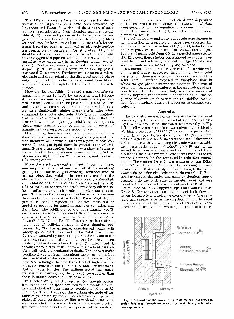
p r e v i o u s l y by Lu (2) a n d c o n s i s t e d of a d i v i d e d cell hav- ing two flow ci rcui ts as i l l u s t r a t ed s c h e m a t i c a l l y in Fig. 1. T h e cell was m a c h i n e d f r o m two p o l y p r o p y l e n e b locks . W o r k i n g e lec t rodes of D S A | (2.7 • 27 c m exposed , Dia- m o n d S h a m r o c k Corpora t ion ) or of P t (2.7 • 26 cm, p r e s s e d aga ins t a 316 SS shee t ) were used . A d j a c e n t to a n d c o p l a n a r w i t h t h e w o r k i n g e lec t rode we re two addi- t i ona l e lec t rodes m a d e of D S A | (2.7 • 10 cm) w h i c h s e r v e d to e l imina te e n t r a n c e a n d exi t effects; of t he se e lec t rodes , t h e d o w n s t r e a m e lec t rode was u s e d as t he ref- e r e n c e e l ec t rode for t h e f e r r i cyan ide r e d u c t i o n exper i - m e n t s . T h e c o u n t e r e l e c t r o d e was m a d e of p o r o u s D S A | (3.1 • 27 cm, D i a m o n d S h a m r o c k Corpora t ion) a n d was p o s i t i o n e d so t h a t e lec t ro ly te f lowed t h r o u g h the pores t o w a r d the w o r k i n g e l ec t rode c o m p a r t m e n t (Fig. 1). Elec- t r ica l c o n t a c t to e l ec t rodes was m a d e b y t i t a n i u m sc rews p r e s s e d on to t h e b a c k s ide of t h e e l ec t rodes a n d was f o u n d to h a v e a c o n t a c t r e s i s t a n c e of less t h a n 0.1~.
A m i c r o p o r o u s p o l y p r o p y l e n e s epa ra to r (Daramic , W.R. Grace & C o m p a n y ) was u s e d to p r e v e n t b u l k flow be- t w e e n t h e ano ly te a n d ca tho ly t e c o m p a r t m e n t s . T h e sepa- r a to r h a d s u p p o r t r ibs in t h e d i rec t ion of flow to avo id b u c k l i n g a n d was he ld at a d i s t ance of 0.2 c m f rom each e l ec t rode surface. On t h e w o r k i n g e l ec t rode side, t he re
Fig. 1. Schematic of the flow circuits inside the cell (not drawn to scale). Reference electrode shown was used for the ferricyanide reduc- tion experiments.
Vol. 132, No. 3 T W O - P H A S E M A S S T R A N S F E R 603
t
Electrode I c~',i I I II I I Y I ~ I
I I L - P-2
I :l Hso,,: I , , +
I I I ~ \ ' FM4- 5 Gouge
Gost,\ /
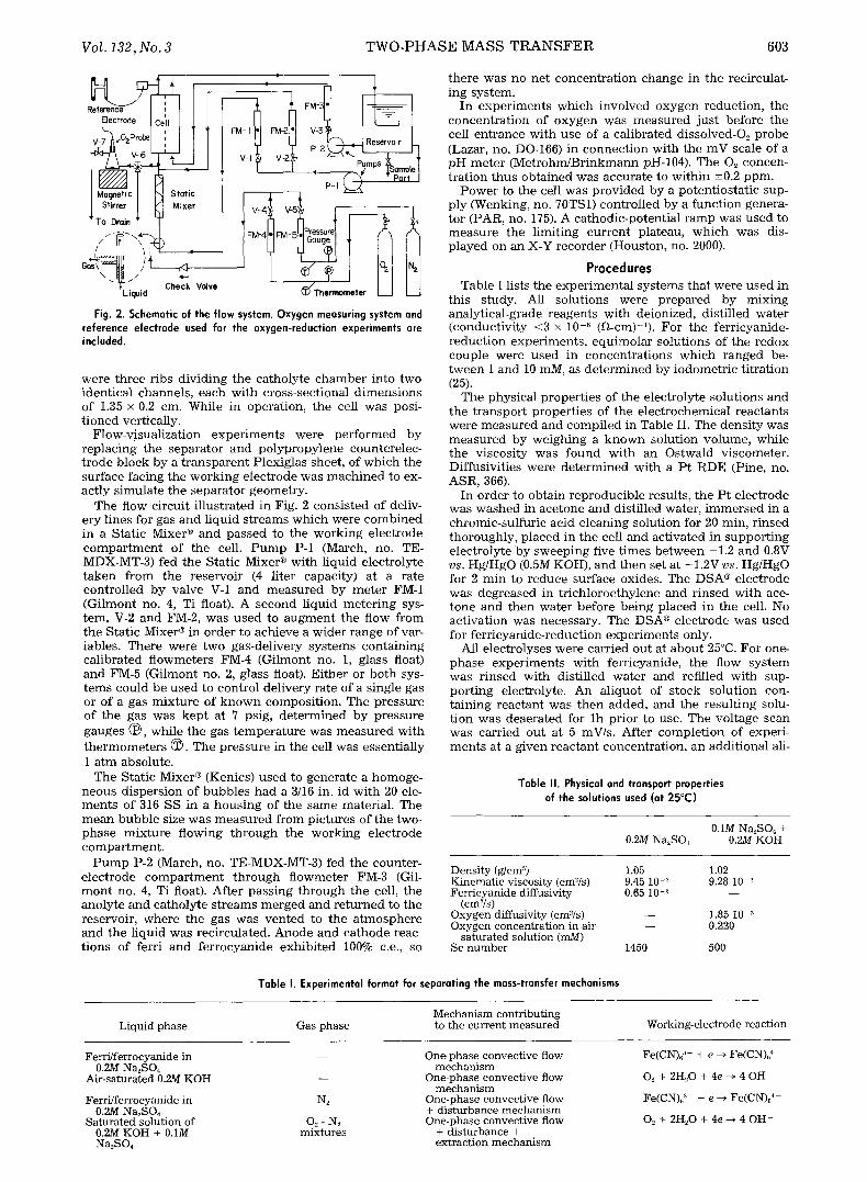
Fig. 2. Schematic of the flow system. Oxygen measuring system and reference electrode used for the oxygen-reduction experiments are included.
were t h r e e r ibs d iv id ing t h e ca tho ly t e c h a m b e r in to two iden t i ca l channe l s , e ach w i t h c ross - sec t iona l d i m e n s i o n s of 1.35 • 0.2 cm. While in opera t ion , t he cell was posi- t i o n e d ver t ical ly .
F low-v i sua l i za t ion e x p e r i m e n t s were p e r f o r m e d by r e p l a c i n g t he s e p a r a t o r a n d p o l y p r o p y l e n e coun te re lec - t r o d e b l o c k by a t r a n s p a r e n t P lex ig las shee t , of w h i c h t he sur face fac ing t he w o r k i n g e l ec t rode was m a c h i n e d to ex- ac t ly s imu la t e t he s epa ra to r geomet ry .
The flow c i rcui t i l l u s t r a t ed in Fig. 2 c o n s i s t e d of deliv- ery l ines for gas a n d l i qu id s t r e a m s w h i c h were c o m b i n e d in a S ta t i c Mixe r | a n d p a s s e d to the w o r k i n g e l ec t rode c o m p a r t m e n t of t he cell. P u m p P-1 (March, no. TE- MDX-MT-3) fed t he S ta t i c Mixe r | w i th l iqu id e lec t ro ly te t a k e n f r o m the r e se rvo i r (4 l i ter capaci ty) at a ra te c o n t r o l l e d b y va lve V-1 a n d m e a s u r e d b y m e t e r FM-1 ( G i l m o n t no. 4, Ti float). A s e c o n d l iqu id m e t e r i n g sys- t em, V-2 a n d FM-2, was u s e d to a u g m e n t t he flow f rom the S ta t i c Mixe r | in o rde r to a ch i eve a w i d e r r a n g e of var- iables . T h e r e were two gas -de l ivery s y s t e m s c o n t a i n i n g ca l i b r a t ed f lowmete r s FM-4 ( G i l m o n t no. 1, glass float) a n d FM-5 (G i lmon t no. 2, glass float). E i t h e r or b o t h sys- t e m s cou ld b e u s e d to con t ro l de l ive ry ra te of a s ingle gas or of a gas m i x t u r e of k n o w n com pos i t i on . T he p r e s s u r e of t he gas was k e p t at 7 psig, d e t e r m i n e d b y p r e s s u r e gauges (~ , wh i l e t he gas t e m p e r a t u r e was m e a s u r e d w i t h t h e r m o m e t e r s (~ . T he p r e s s u r e in t he cell was essen t i a l ly 1 a t m abso lu te .
The S ta t i c Mixer | (Kenics) u s e d to g e n e r a t e a h o m o g e - n e o u s d i s p e r s i o n of b u b b l e s h a d a 3/16 in. id w i t h 20 ele- m e n t s of 316 SS in a h o u s i n g of t he s a m e mater ia l . The m e a n b u b b l e size was m e a s u r e d f rom p i c tu r e s of t h e two- p h a s e m i x t u r e f lowing t h r o u g h t he w o r k i n g e l ec t rode c o m p a r t m e n t .
P u m p P-2 (March, no. TE-MDX-MT-3) fed t he coun te r - e l ec t rode c o m p a r t m e n t t h r o u g h f l owmete r FM-3 (Gil- m o n t no. 4, Ti float). Af te r p a s s i n g t h r o u g h t he cell, t h e ano ly t e a n d ca tho ly t e s t r e a m s m e r g e d a n d r e t u r n e d to t he reservoi r , w h e r e t he gas was v e n t e d to t he a t m o s p h e r e a n d t he l iqu id was rec i rcu la ted . A n o d e a n d c a t h o d e reac- t ions of ferr i a n d f e r r o c y a n i d e e x h i b i t e d 100% c.e., so
t h e r e was no ne t c o n c e n t r a t i o n c h a n g e in t he rec i rcula t - ing sys tem.
In e x p e r i m e n t s w h i c h i n v o l v e d o x y g e n r educ t ion , t he c o n c e n t r a t i o n of o x y g e n was m e a s u r e d j u s t be fo re the cell e n t r a n c e w i t h use of a ca l ib ra t ed dissolved-O2 p r o b e (Lazar, no. DO-166) in c o n n e c t i o n w i t h t h e m V scale of a p H m e t e r ( M e t r o h m / B r i n k m a n n pH-104). The 02 concen- t r a t i on t h u s o b t a i n e d was accu ra t e to w i t h i n -+0.2 ppm.
P o w e r to t he cell was p r o v i d e d b y a po t en t i o s t a t i c sup- p ly (Wenking, no. 70TS1) con t ro l l ed by a f u n c t i o n genera- to r (PAR, no. 175). A ca thod i c -po t en t i a l r a m p was u s e d to m e a s u r e the l imi t ing c u r r e n t p la teau , w h i c h was dis- p l a y e d on a n X-Y r e c o r d e r (Hous ton , no. 2000).
Procedures Tab le I l ists t h e e x p e r i m e n t a l sy s t ems t h a t we re u s e d in
th i s s tudy. All so lu t ions were p r e p a r e d by m i x i n g ana ly t i ca l -g rade r e a g e n t s w i t h de ionized, d is t i l led w a t e r ( conduc t iv i t y <3 • 10 -4 (~-cm)- l ) . Fo r the fe r r i cyan ide- r e d u c t i o n e x p e r i m e n t s , e q u i m o l a r so lu t ions of t he r edox c o u p l e were u s e d in c o n c e n t r a t i o n s w h i c h r a n g e d be- t w e e n 1 a n d 10 mM, as d e t e r m i n e d by i o d o m e t r i c t i t r a t ion (25).
T h e phys ica l p r o p e r t i e s of t he e lec t ro ly te so lu t ions a n d t h e t r a n s p o r t p r o p e r t i e s of t he e l e c t r o c h e m i c a l r e a c t a n t s were m e a s u r e d a n d c o m p i l e d in Tab le II. The dens i t y was m e a s u r e d by w e i g h i n g a k n o w n so lu t ion vo lume , whi l e t he v i scos i ty was f o u n d w i t h a n Os twa ld v i scomete r . Di f fus iv i t ies we re d e t e r m i n e d w i t h a P t R D E (Pine, no. ASR, 366).
I n o rde r to ob ta in r e p r o d u c i b l e resul ts , t h e P t e l ec t rode was w a s h e d in a ce tone a n d dis t i l led water , i m m e r s e d in a ch romic - su l fu r i c ac id c l ean ing so lu t ion for 20 rain, r i n s e d t ho rough ly , p l aced in t he cell a n d ac t iva ted in s u p p o r t i n g e lec t ro ly te b y s w e e p i n g five t i m e s b e t w e e n -1 .2 a n d 0.8V vs. Hg/HgO (0.5M KOH), a n d t h e n set a t - 1.2V vs. Hg/HgO for 2 m i n to r e d u c e sur face oxides. The D S A | e l ec t rode was deg rea sed in t r i c h l o r o e t h y l e n e a n d r i n s e d w i t h ace- t one a n d t h e n wa te r be fo re b e i n g p l aced in t he cell. No ac t i va t i on was necessa ry . The D S A | e l ec t rode was u s e d for f e r r i cyan ide - r educ t i on e x p e r i m e n t s only.
All e lec t ro lyses were ca r r ied ou t at a b o u t 25~ Fo r one- p h a s e e x p e r i m e n t s w i th fe r r icyanide , t he flow s y s t e m was r i n s e d w i th d is t i l led w a t e r a n d refi l led w i t h sup- p o r t i n g electrolyte . A n a l iquo t of s tock so lu t ion con- t a i n i n g r e a c t a n t was t h e n added , a n d t he r e s u l t i n g solu- t ion was d e a e r a t e d for l h p r io r to use. The vo l t age scan was ca r r ied ou t at 5 mV/s. Af te r c o m p l e t i o n of exper i - m e n t s at a g iven r e a c t a n t concen t r a t i on , a n a d d i t i o n a l all-
Table II. Physical and transport properties of the solutions used (at 25~
0.1M Na2SO4 + 0.2M Na2SO4 0.2M KOH
Density (g/em :~) 1.05 1.02 Kinematic viscosity (cm2/s) 9.45 10 -:~ 9.28 10 :~ Ferricyanide diffusivity 0.65 10 -s - -
(cm'-Vs) Oxygen diffusivity (cm~/s) - - 1.85 1O -s Oxygen concentration in air- - - 0.220
saturated solution (mY/) Sc number 1450 500
Table I. Experimental format for separating the mass-transfer mechanisms
Mechanism contributing Liquid phase Gas phase to the current measured Working-electrode reaction
Ferri/ferrocyanide in 0.2M Na~SO4
Air-saturated 0.2M KOH
Ferri/ferrocyanide in N2 0.2M Na2SO4
Saturated solution of O~ - N._, 0.2M KOH + 0.1M mixtures Na2SO4
One-phase convective flow mechanism
One-phase convective flow mechanism
One-phase convective flow + disturbance mechanism One-phase convective flow
+ disturbance + extraction mechanism
Fe(CN),"- + e --* Fe(CN)/
O.2 + 2H~O + 4e --* 4 OH-
Fe(CN)d ' - + e --* Fe(CN)~ 4-
02 + 2H~O + 4e --~ 4 OH-
604 J. E l e c t r o c h e m . Soc.: E L E C T R O C H E M I C A L
quot of stock solution containing reactant was added to increase the concentration to a new level, and the proce- dure was repeated.
For two-phase ferricyanide-inert gas experiments, the procedure was identical, except than N,,, gas was metered into the Static Mixer C''', and the scan rate was 10 mV/s. Limiting currents were measured in sequence of experi- ments, each at constant liquid flow rate with succes- sively increasing gas flow rates.
For one-phase experiments with dissolved oxygen as the reactant, the electrolyte was circulated through the flow system for 30 min while air was sparged into the res- ervoir. The Pt electrode was then activated, the O~ con- centration was measured with the dissolved oxygen probe, and current-potential curves were recorded at a scan rate of 5 mV/s. A Hg/HgO (0.5M KOH) reference elec- trode (built in-house) was used for all the experiments involving the O~ reduction reaction.
For two-phase experiments with reactive gas bubbles, air, or other N2-O~ mixtures (depending on the desired O~ concentration) were dispersed in the electrolyte phase. The procedure was similar to that followed for the two- phase inert-gas experiments, except that special care was taken to ensure that the Pt electrode remained active. The electrode was periodically reactivated, and the gas was periodically shut off and a one-phase experiment was carried out to confirm reproducibility of the Pt surface. Repeated experiments were reproducible to within 3% for one-phase flow and to within 12% for two-phase flow with reactive gas. Two-phase inert-gas experiments were reproducible to within 5%.
Results Flow v isual iza t ion . - -Flow-visual iza t ion experiments in-
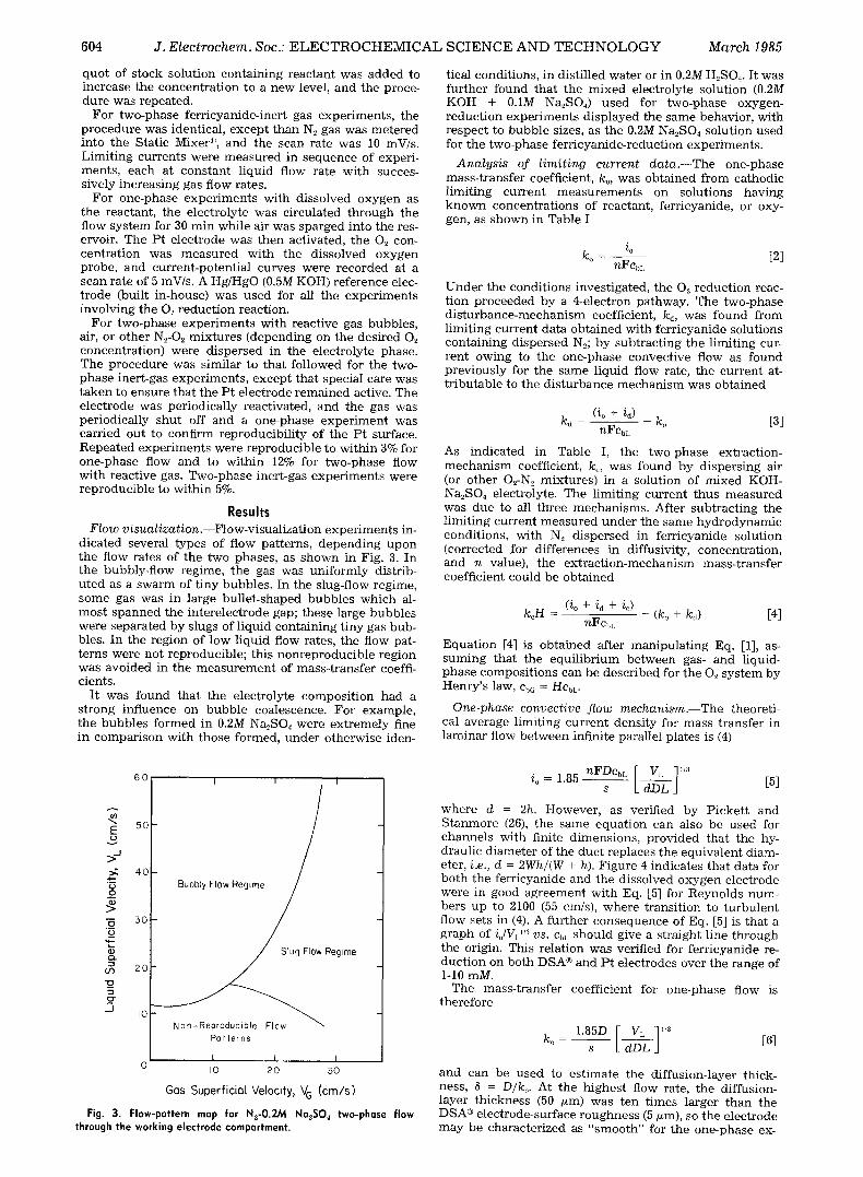
dicated several types of flow patterns, depending upon the flow rates of the two phases, as shown in Fig. 3. In the bubbly-flow regime, the gas was uniformly distrib- uted as a swarm of tiny bubbles. In the slug-flow regime, some gas was in large bullet-shaped bubbles which al- most spanned the interelectrode gap; these large bubbles were separated by slugs of liquid containing tiny gas bub- bles. In the region of low liquid flow rates, the flow pat- terns were not reproducible; this nonreproducible region was avoided in the measurement of mass-transfer coeffi- cients.
It was found that the electrolyte composition had a strong influence on bubble coalescence. For example, the bubbles formed in 0.2M Na2SO4 were extremely fine in comparison with those formed, under otherwise iden-
SCIENCE AND TECHNOLOGY March 1985
tical conditions, in distilled water or in 0.2M H2SO4. It was further found that the mixed electrolyte solution (0.2M KOH + 0.1M Na2SO4) used for two-phase oxygen- reduction experiments displayed the same behavior, with respect to bubble sizes, as the 0.2M Na2SO4 solution used for the two-phase ferricyanide-reduction experiments.
Analys i s of l imi t ing current d a t a . - - T h e one-phase mass-transfer coefficient, ko, was obtained from cathodic limiting current measurements on solutions having known concentrations of reactant, ferricyanide, or oxy- gen, as shown in Table I
i o ko - [2]
nFCbl.
Under the conditions investigated, the 0`-, reduction reac- tion proceeded by a 4-electron pathway. The two-phase disturbance-mechanism coefficient, ks, was found from limiting current data obtained with ferricyanide solutions containing dispersed N2; by subtracting the limiting cur- rent owing to the one-phase convective flow as found previously for the same liquid flow rate, the current at- tributable to the disturbance mechanism was obtained
(io + id) kd - - - ko [3]
nFCbL
AS indicated in Table I, the two-phase extraction- mechanism coefficient, k~, was found by dispersing air (or other O2-N,,, mixtures) in a solution of mixed KOH- Na2SO4 electrolyte. The limiting current thus measured was due to all three mechanisms. After subtracting the limiting current measured under the same hydrodynamic conditions, with N2 dispersed in ferricyanide solution (corrected for differences in diffusivity, concentration, and n value), the extraction-mechanism mass-transfer coefficient could be obtained
( i o + i d + i ~ ) keH - (ko + ks) [4]
nFCbL
Equation [4] is obtained after manipulating Eq. [1], as- suming that the equil ibrium between gas- and liquid- phase compositions can be described for the 0`-, system by Henry's law, CbG = HCbL.
One-phase convective f low mechan i sm . - -The theoreti- cal average limiting current density for mass transfer in laminar flow between infinite parallel plates is (4)
60 L I I
E 5o
>.-, 4oi
'~ Bubbly Flow Regtm
"6 5O _5
R e g i m e r-.,
co 2o
._o-
._1 I0
Non-Reproduc ib le Flow \ Pot terns
I I I 0 ]0 2 0 50
Gas Superficial Velocity, V G (cm/s)
Fig. 3, Flow-pattern map for N2-O.2M Na2S04 two-phase flow through the working electrode compartment.
io= 1.85 -nFDcbL [ VL ],3 L dDL J [5]
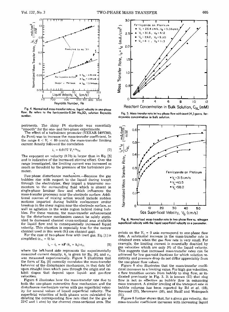
where d = 2h. However, as verified by Pickett and Stanmore (26), the same equation can also be used for channels with finite dimensions, provided that the hy- draulic diameter of the duct replaces the equivalent diam- eter, i.e., d = 2Wh/(W + h). Figure 4 indicates that data for both the ferricyanide and the dissolved oxygen electrode were in good agreement with Eq. [5] for Reynolds num- bers up to 2100 (55 cm/s), where transition to turbulent flow sets in (4). A further consequence of Eq. [5] is that a graph of iJVL "3 vs. ChL should give a straight line through the origin. This relation was verified for ferricyanide re- duction on both DSA | and Pt electrodes over the range of 1-10 raM.
The mass-transfer coefficient for one-phase flow is therefore
1.85D [ V L ]1/3 ko - s L dDL J [6]
and can be used to estimate the diffusion-layer thick- ness, 8 = D/ko. At the highest flow rate, the diffusion- layer thickness (50 ~m) was ten times larger than the DSA | electrode-surface roughness (5 t~m), so the electrode may be characterized as "smooth" for the one-phase ex-
Vol. 132, No. 3 TWO-PHASE MASS TRANSFER 605
o
Z
15 I I I I I II I I I I I I I
1.0
0 .5
Predicted by eq. (5) o.2 - / . I
/
" I'-- Oxyg . . . . elQtinum : : : : : : i : : : M ~ r Fe r ricyoNide o13 DSA~ -- rnM:
o , " ' " o ' Liquid Velocity, V L (cm/s) I I , , , , , I
I10 200 500 I000 1500 2i00 3100 Reynolds Number, Re
Fig. 4. Normalized mass-transfer rate vs. liquid velocity in one-phase flow. Re refers to the ferricyanide-O.2M Na2S04 solution Reynolds number.
E (.3 < E
+ 0
O
U) E
q J) U) o
3.0 I I I I I Fer r i cyan ide on P l a t i n u m . ~ " VL= 25'4cm/s,Ve =3 '06cm/s/ / . ~
2.5 �9 VL= 31.6, Ve=4.'2 / / / �9 VL= 29.2, Ve=9.50 V / / /
2'0 , v vL=41'. ' VG = / / ~
1"5 1
1 .0 -
0 . 5 - -
i i l l I 0
2 4. 6 8 I0 12
Reactant Concentration in Bulk Solution, CbL(mM) Fig. 5. Mass-transfer rate in two-phase flow with inert (N2) gasvs, fer-
ricyanide concentration in bulk solution.
periments. The shiny Pt electrode was essentially "smooth" for the one- and two-phase experiments.
The effect of a turbulence promoter (VEXAR 549V300, du Pont) was to increase the mass-transfer coefficient. In the range 6 < VL < 60 (cm/s), the mass-transfer limiting current density followed the correlation
io = 0.0177 VL~176 [7]
The exponent on velocity (0.70) is larger than in Eq. [5] and is indicative of the increased stirring effect. Over the range investigated, the limiting current was increased as much as threefold by the presence of the turbulence pro- moter.
Two-phase disturbance mechanism.--Because the gas bubbles rise with respect to the liquid during transit through the electrolyzer, they impart a transverse mo- mentum to the surrounding fluid which is absent in single-phase laminar flow and which influences the mass-transfer processes near the electrode surface. Addi- tional sources of mixing action would include sudden motions imparted during bubble coalescence and/or breakup in the shear region near the electrode surface, as well as agitation in the wake region behind rising bub- bles. For these reasons, the mass-transfer enhancement by the disturbance mechanism cannot be solely attrib- uted to decreased channel cross-sectional area available for liquid flow and to consequentially increased liquid velocity, This situation is especially true for the narrow channel used in this work (0.2 cm channel gap).
For the case of two-phase flow with inert gas, Eq. [1] is simplified (ch~; = 0) to
io + id = nF (k,, + kd) CbL [8]
where the left-hand side represents the experimentally measured current density, ko is given by Eq. [6], and C~,L was measured experimentally. Figure 5 illustrates that the form of Eq. [8] correctly correlates the mass-transfer behavior of the disturbance mechanism, in that data fall upon straight lines which pass through the origin and ex- hibit slopes that depend upon liquid- and gas-flow velocities.
Figure 6 illustrates how the mass-transfer rate due to both the one-phase convective flow mechanism and the disturbance mechanism varies with gas superficial veloc- ity for several values of liquid superficial velocity. The superficial velocities of both phases were calculated by dividing the corresponding flow rate (that for the gas at 25~ and 1 atm) by the channel cross-sectional area. The
. o ~ 0.6
0.5 �9 - "
%
0.4
O
~ 0.3 m E
0.2 co 0
"o ',
.N 0.1' O E
Z 0
' ' "1
f "VL=N.5 cm/s �9 VL=43. 5 " VL ' 580
I i I I I I0 20 30 40 50
Gas Superficial Velocity, V G (cm/s)
Fig. 6. Normalized mass-transfer rate in two-phase flow vs. nitrogen superficial velocity with the liquid superficial velocity as a parameter.
points on the V~ = 0 axis correspond to one-phase flow data. A substantial increase in the mass-transfer rate is obtained even when the gas flow rate is very small. For example, the limiting current is essentially doubled by gas velocities which are only 5% of the liquid velocity. This suggests that increased mass-transfer rates can be achieved for low gas-void fractions for which solution re- sistivity and pressure drop do not differ appreciably from the one-phase flow values.
Figure 6 also illustrates that the mass-transfer coeffi- cient increases to a limiting value. For high gas velocities, a flow transition occurs from bubbly to slug flow, as in- dicated previously in Fig. 3. It is known (27) that slug flow is not as effective as bubbly flow in enhancing mass transport. A similar leveling of the transport rate in bubble columns has been reported by Ibl et al. (18), Novosad (27), Mersmann (10), and Steiff and Weinspach (11).
Figure 6 further shows that, for a given gas velocity, the mass-transfer coefficient increases with increasing liquid
606 J . E l e c t r o c h e m . S o c . : E L E C T R O C H E M I C A L S C I E N C E A N D T E C H N O L O G Y M a r c h 1 9 8 5
velocity, a result which is in contrast to that reported by Sigrist et al. (20). However, in their experimental system, the interelectrode gap was at least five times wider than that used here, and, additionally, the liquid velocity em- ployed was too low to be used in the present system while remaining in the bubbly flow regime. The explanation of these data by Ibl (21) was based on turbulent natural- convection concepts. Sigrist et al. realized that a decrease in the mass transfer with increasing liquid velocity (at constant gas velocity) would be observed provided that the liquid velocity is not too large. In studies of heat transfer in two-phase flow, others have reported condi- tions where the heat-transfer coefficient increases with liquid velocity (28) at high gas flow rates and where the coefficient is insensitive to liquid velocity (II) at low liq- uid flow rates. Thus it may be concluded that the dis- turbance effect is complex and that it depends upon the particular flow regime of operation. In the present work, the liquid velocity is appreciably higher than considered previously (20, 21), so explanations of behavior cannot be based on natural-convection phenomena.
Figure 6 also demonstrates that the disturbance mecha- nism can enhance the one-phase mass-transfer rate by up to 400%. Similarly, large enhancement factors have been reported elsewhere (ii). In contrast, in studies on two- phase liquid-liquid systems, Lu and Alkire (2) reported an increase of up to 170%. The substantially greater enhance- ment in gas-liquid systems results from the significantly greater bubble-rise velocities in comparison with liquid droplets, owing to a greater density difference.
When the data in Fig. 6 are replotted on log-log coordi- nates, a slope of approximately 0.25 is found, which com- pares favorably to experimental and theoretical results re- ported for bubble columns (12).
After subtracting the contribution of the one-phase con- vective flow, the enhancement of mass transfer by the disturbance mechanism was found to be expressed by the empirical correlation
id = 0.007 VLO'74VG~ [9]
w h i c h desc r ibes the data , for the bubb l y - f l ow reg ime, to w i t h i n 8%.
Fo r t he t w o - p h a s e iner t -gas e x p e r i m e n t s , t he DSA | e l ec t rode gave c u r r e n t s w h i c h were a b o u t 10% h i g h e r t h a n on t he P t e lec t rode . B e c a u s e t he t w o - p h a s e mass- t r a n s f e r b o u n d a r y layer c an b e as t h i n as 10/~m, th i s ef- fect was a t t r i b u t e d to t h e r o u g h n e s s of the D S A | ma te r i a l (about 5/~m), while the shiny Pt was essentially smooth.
By using two different Static Mixers | it was possible to vary the mean bubble diameter by a factor of two. For the 3/16 in. unit, the diameter ranged between 200 and 600 /~m, and for a I/4 in. unit, the diameter ranged between 400 and 1200/~m. The effect of bubble size upon the mass- transfer rate was smaller than 5%. Others have reported similar observations in both gas-liquid (18, 29) and liquid- liquid systems (2).
When a turbulence promoter was placed in the flow channel, the influence upon two-phase inert-gas mass transfer was negligible. These results suggest that the two-phase mixture was by its nature "well mixed" and that the turbulence promoter provided little additional mixing..While the promoter might be expected to alter the mean bubble size, the results of the previous para- graph indicate that the mass-transfer enhancement is in- sensitive to bubble size.
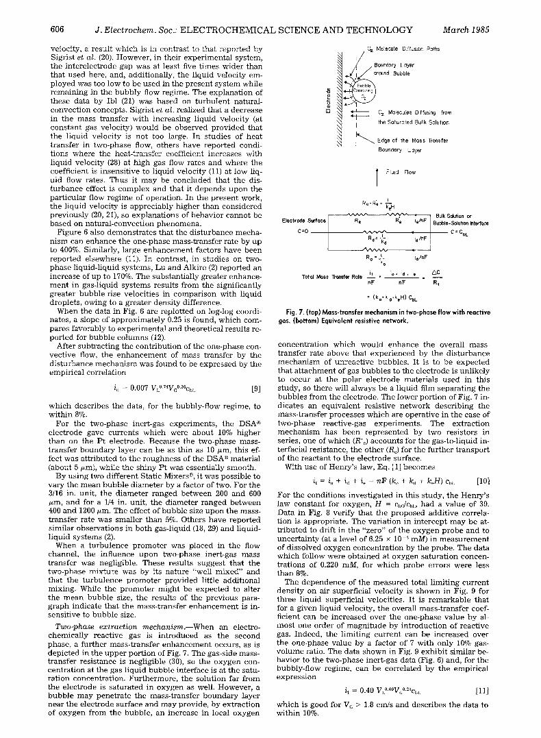
T w o - p h a s e e x t r a c t i o n m e c h a n i s m . - - W h e n a n electro- c h e m i c a l l y r eac t ive gas is i n t r o d u c e d as t he s e c o n d phase , a f u r t h e r m a s s - t r a n s f e r e n h a n c e m e n t occurs , as is d e p i c t e d in t he u p p e r p o r t i o n of Fig. 7. T he gas-s ide mass- t r a n s f e r r e s i s t ance is neg l ig ib l e (30), so t he o x y g e n con- c e n t r a t i o n a t t he gas - l iqu id b u b b l e in t e r f ace is a t t he satu- r a t i o n concen t r a t i o n . F u r t h e r m o r e , t he so lu t i on far f rom the e l ec t rode is s a t u r a t e d in o x y g e n as well. However , a b u b b l e m a y p e n e t r a t e t he m a s s - t r a n s f e r b o u n d a r y layer nea r t he e l ec t rode sur face a n d m a y prov ide , by e x t r a c t i o n of o x y g e n f rom the b u b b l e , a n inc rease in local o x y g e n
Q'z Molecule Diffusion Foths
/ / Boundary Loyer
~/i / oround Bubble
4 I O~ Molecules Diffusing from
X~ the Soturoted Bulk Soluhon I I i ~ " ' - ~ Edge of the Moss Tronsfer
Boundary Layer
Fluid Flow
Re,R'e = I__ keH
. JN/vvx~ i Electrode Surface R e R" e le/nF
C=O ~ l 4 Rd= ~'d Jd/nF
R o = ~ lo/nF k o
iT i o , i,t + i e Tofol Mess Transfer Role - - - - - =
nF nF
Bulk Sdution or Bubble-Solution hterfece
C = CbL
AC
Rt
= (ko*kd,keH) CbL
Fig. 7. (top) Mass-transfer mechanism in two-phase flow with reactive gas. (bottom) Equivalent resistive network.
c o n c e n t r a t i o n w h i c h w o u l d e n h a n c e t he overal l mass- t r a n s f e r ra te a b o v e t h a t e x p e r i e n c e d by t he d i s t u r b a n c e m e c h a n i s m of u n r e a c t i v e b u b b l e s . I t is to b e e x p e c t e d t h a t a t t a c h m e n t of gas b u b b l e s to t he e l ec t rode is un l ike ly to occu r at t he po la r e l ec t rode ma te r i a l s u s e d in th i s s tudy , so t he re will a lways be a l iqu id film s e p a r a t i n g the b u b b l e s f rom the e lec t rode . The lower po r t i on of Fig. 7 in- d ica tes an e q u i v a l e n t r es i s t ive n e t w o r k d e s c r i b i n g t he m a s s - t r a n s f e r p r o c e s s e s w h i c h are opera t ive in t he case of t w o - p h a s e reac t ive-gas e x p e r i m e n t s . The e x t r a c t i o n m e c h a n i s m has b e e n r e p r e s e n t e d b y two res i s to rs in series, one of w h i c h (R%) a c c o u n t s for the gas- to- l iquid in- te r fac ia l res i s tance , the o the r (Re) for t he f u r t h e r t r a n s p o r t of t he r e a c t a n t to t he e l ec t rode surface.
Wi th u se of H e n r y ' s law, Eq. [1] b e c o m e s
it = io + id + ie = n F (ko + kd + keH) cb,. [10]
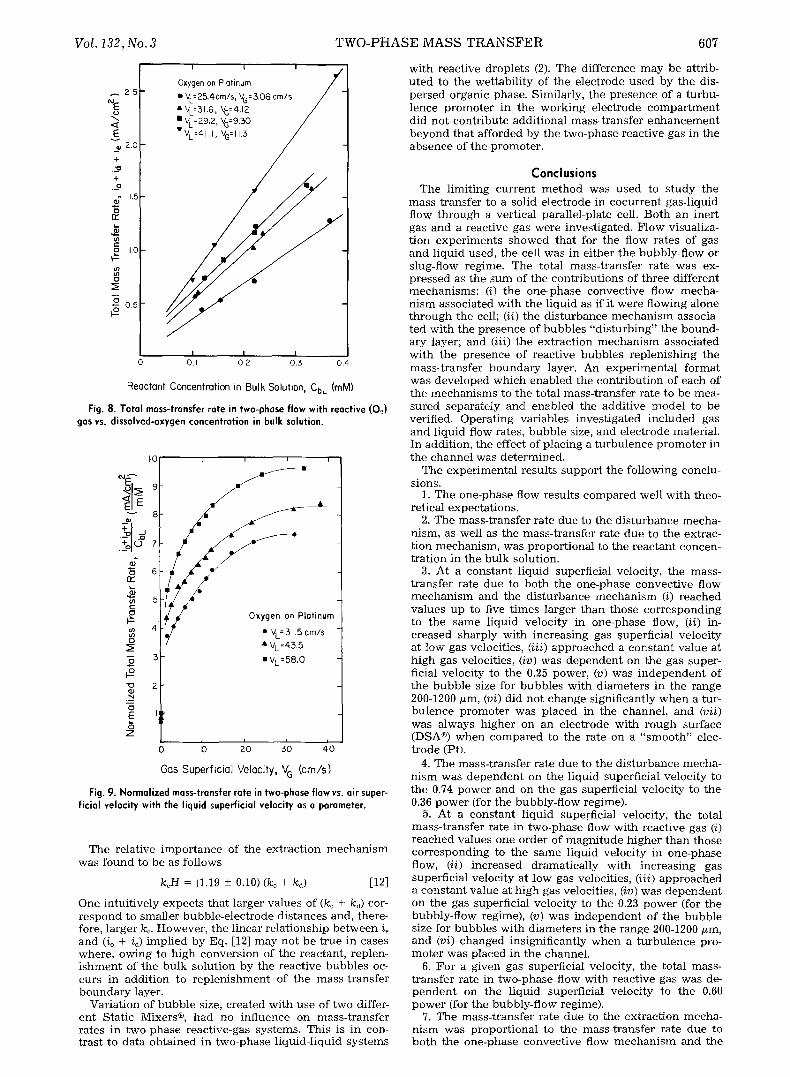
F o r t he c o n d i t i o n s i n v e s t i g a t e d in th i s s tudy , t he H e n r y ' s l aw c o n s t a n t for oxygen , H = Cbc]C~L, h a d a v a l u e of 39. Da ta in Fig. 8 ver i fy t h a t the p r o p o s e d add i t i ve correla- t ion is appropr ia t e . The va r i a t i on in i n t e r c e p t m a y b e at- t r i b u t e d to dr if t i n t h e "ze ro" of the o x y g e n p r o b e a n d to u n c e r t a i n t y (at a level of 6.25 • 10-:~ raM) in m e a s u r e m e n t of d i s so lved o x y g e n c o n c e n t r a t i o n b y the p robe . The da ta w h i c h fo l low were o b t a i n e d at o x y g e n - s a t u r a t i o n concen - t r a t i ons of 0.220 raM, for w h i c h p r o b e er rors were less t h a n 8%.
The d e p e n d e n c e of t he m e a s u r e d to ta l l im i t ing c u r r e n t dens i t y on air superf ic ia l ve loc i ty is s h o w n in Fig. 9 for t h r e e l iqu id superf ic ia l veloci t ies . I t is r e m a r k a b l e t h a t for a g iven l iqu id veloci ty , t he overal l m a s s - t r a n s f e r coef- f icient can be i n c r e a s e d over t he o n e - p h a s e va lue b y al- m o s t one o rde r of m a g n i t u d e by i n t r o d u c t i o n of r eac t ive gas. Indeed , the l im i t i ng c u r r e n t can be i n c r e a s e d over t he o n e - p h a s e va lue by a fac to r of 7 w i t h on ly 10% gas- v o l u m e ratio. The da ta s h o w n in Fig. 9 e x h i b i t s imi la r be- hav io r to t he t w o - p h a s e iner t -gas data (Fig. 6) and, for the bubb ly - f low reg ime, c a n be co r re la t ed by t he empi r i ca l e x p r e s s i o n
i t = 0.40 V,~176 [11]
w h i c h is good for V~ > 1.8 crrgs a n d desc r ibe s the da ta to w i t h i n 10%.
Vol. 132, No. 3
~ 2 5
<~ E e 2.0
+
+ .._o
- 1 , 5 e) o cr
a IO #
0 .5
i i i
Oxygen on Platinum
�9 VL=ES,4cm/s , VG = 3,06 cm/s
�9 VL=31.6 , VG=4.J2 �9 v,=29.2, vG=9.~o " VL=41,1 , VG= 11.5 /
0 O. I 0 2 0 , 3 0 , 4
Reactant Concentration in Bulk Soluhon, CbL (raM)
Fig. 8. Total mass-transfer rate in two-phase flow with reactive (0,2) gas vs. dissolved-oxygen concentration in bulk solution.
I0
-9.~ 9
2" s
6
4 o
-@ 3
2
o E
Z
I i i i
�9 VL =58.0
0 I0 2 0 0 0
Gas Superficial Velocity, V G (cm/s)
Fig. 9. Normalized mass-transfer rate in two-phase flow vs. air super- ficial velocity with the liquid superficial velocity as a parameter.
The relat ive impor tance of the ex t rac t ion m e c h a n i s m was found to be as fol lows
k~H = (1.19 -+ 0.10) (/co + kd) [12]
One in tui t ively expec t s that larger va lues of (ko + kd) cor- respond to smal ler bubb le -e lec t rode d is tances and, there- fore, larger ke. However , the l inear re la t ionship b e t w e e n i~ and (io + id) impl ied by Eq. [12] may not be t rue in cases where, owing to h igh convers ion of the reactant , replen- i shmen t of the bulk solut ion by the react ive bubbles oc- curs in addi t ion to r ep l en i shmen t of the mass- t ransfer boundary layer.
Var ia t ion of bubb le size, created wi th use of two differ- en t Stat ic Mixers | , had no inf luence on mass- t ransfer rates in two-phase react ive-gas systems. This is in con- trast to data obta ined in two-phase l iquid- l iquid sys tems
T W O - P H A S E M A S S T R A N S F E R 607
with react ive droplets (2). The di f ference may be attrib- u ted to the wet tabi l i ty of the e lec t rode used by the dis- persed organic phase. Similarly, the p resence of a turbu- lence p romote r in the work ing e lec t rode c o m p a r t m e n t did no t cont r ibute addi t ional mass- t ransfer e n h a n c e m e n t beyond that afforded by the two-phase react ive gas in the absence of the promoter .
Conclusions The l imi t ing cur ren t m e t h o d was used to s tudy the
mass t ransfer to a solid e lec t rode in cocur ren t gas-l iquid flow th rough a ver t ica l parallel-plate cell. Bo th an inert gas and a react ive gas were invest igated. F low visualiza- t ion expe r imen t s showed that for the flow rates of gas and l iquid used, the cell was in ei ther the bubbly-f low or slug-flow regime. The total mass- t ransfer rate was ex- p ressed as the s u m of the cont r ibu t ions of three di f ferent mechan i sms : (i) the one-phase convec t ive flow mecha- n i sm associated wi th the l iquid as if it were f lowing alone th rough the cell; (ii) the d i s tu rbance m e c h a n i s m associa- ted wi th the p resence of bubbles "d i s tu rb ing" the bound- ary layer; and (iii) the ex t rac t ion m e c h a n i s m associated wi th the presence of reac t ive bubbles rep len i sh ing the mass- t ransfer boundary layer. An expe r imen ta l format was deve loped which enabled the cont r ibut ion of each of the mechan i sms to the total mass- t ransfer rate to be mea- sured separately and enabled the addi t ive mode l to be verified. Operat ing var iables inves t iga ted inc luded gas and l iquid flow rates, bubb le size, and e lec t rode material . In addit ion, the effect of p lac ing a tu rbu lence p romote r in the channel was de te rmined .
The exper imenta l resul ts suppor t the fo l lowing conclu- sions.
1. The one-phase flow resul ts compared well wi th theo- ret ical expecta t ions .
2. The mass- t ransfer rate due to the d i s tu rbance mecha- nism, as well as the mass- t ransfer rate due to the extrac- t ion mechan ism, was propor t iona l to the reactant concen- t ra t ion in the bulk solution.
3. At a constant l iquid superficial veloci ty, the mass- t ransfer rate due to both the one-phase convec t ive flow m e c h a n i s m and the d i s tu rbance m e c h a n i s m (i) reached va lues up to five t imes larger than those cor respond ing to the same l iquid ve loc i ty in one-phase flow, (ii) in- c reased sharply wi th increas ing gas ~uperficial ve loc i ty at low gas veloci t ies , (iii) approached a cons tan t va lue at h igh gas velocit ies, (iv) was d e p e n d e n t on the gas super- ficial ve loc i ty to the 0.25 power, (v) was i n d e p e n d e n t of the bubb le size for bubbles wi th d iameters in the range 200-1200/xm, (vi) did not change signif icantly w h e n a tur- bu lence p romote r was p laced in the channel , and (vii) was always h igher on an e lec t rode wi th rough surface (DSA | w h e n compared to the rate on a " s m o o t h " elec- t rode (Pt).
4. The mass- t ransfer rate due to the d i s tu rbance mecha- n i sm was d e p e n d e n t on the l iquid superficial ve loc i ty to the 0.74 power and on the gas superficial ve loc i ty to the 0.36 power (for the bubbly-f low regime).
5. At a cons tant l iquid superficial veloci ty , the total mass- t ransfer rate in two-phase flow wi th reac t ive gas (i) r eached values one order of magn i tude h igher than those cor respond ing to the same l iquid ve loc i ty in one-phase flow, (ii) increased dramat ica l ly wi th increas ing gas superficial ve loci ty at low gas veloci t ies , (iii) approached a cons tan t va lue at h igh gas velocit ies, (iv) was d e p e n d e n t on the gas superficial ve loc i ty to the 0.23 power (for the bubbly-f low regime), (v) was i ndependen t of the bubble size for bubbles wi th d iameters in the range 200-1200/xm, and (vi) changed insignif icant ly w h e n a t u rbu l ence pro- mote r was p laced in the channel .
6. Fo r a g iven gas superf icial veloci ty, the total mass- t ransfer rate in two-phase flow wi th react ive gas was de- p e n d e n t on the l iquid superficial ve loc i ty to the 0.60 power (for the bubbly-f low regime).
7. The mass- t ransfer rate due to the ex t rac t ion mecha- n i sm was propor t iona l to the mass- t ransfer rate due to bo th the one-phase convec t ive flow m e c h a n i s m and the
608 J. Electrochem. Soc.: E L E C T R O C H E M I C A L S C I E N C E A N D T E C H N O L O G Y March 1985
disturbance mechanism, the proportionality factor being 1.19 -+ 0.10.
The results of this study showed that the use of two- phase flow in electrochemical reactors incorporating a gas which is sparingly soluble in the liquid phase may be highly advantageous. In particular, high mass-transfer rates can be achieved at low gas-volume fractions. Thus, the solution resistivity and the pressure drop through the system do not differ significantly from the corresponding values in one-phase flow. Consider for example the case of a gas-void fraction e = 10%. The conductivity of the so- lution (31) will be K = Ko(1 - e) ~.5 = 0.85Ro, and the energy consumption due to IR drop will increase by about 15%. Moreover, the pressure drop (32) will be
dP _ ( 1 + e ~ dP dP
and the energy consumption for pumping will be 22% higher than that when operating in one-phase flow with the same liquid velocity. However, even at e = 10%, the mass-transfer rate can be up to seven times that in one- phase flow (Fig. 9), which amounts to a 600% increase in productivity if the process is mass-transfer limited.
~_is work dealt with the case of negligible conversion per pass of the reactant through the cell. The enhance- ment due to the extraction mechanism was solely attrib- uted to bubbles resaturating depleted regions within the mass-transfer boundary layer ~. In situations where the reactant conversion is high, however, the presence of the reactive bubbles resaturating the bulk solution as well will make the contribution of the extraction mechanism even more significant.
Acknowledgments Financial support of this work was provided by the Na-
tional Science Foundation (CPE 80-08947) and by a Uni- versity of Illinois Fellowship.
Manuscript submitted April 5, 1984; revised manuscript received July 31, 1984.
University of Illinois assisted in meeting the publication costs of this article.
LIST OF SYMBOLS
c reactant concentration, mM d equivalent diameter, cm D reactant diffusivity, cm2/s F Faraday constant, 96,500 C/g-eq h gap of flow channel, cm H constant in Henry's law (= c~,Jc~,r) i current density, mA/cm ~ k mass-transfer coefficient, cm/s L electrode length, cm n number of electrons exchanged in electrode reac-
tion P pressure, dyn/cm 2 R equivalent mass-transfer resistance, s/cm Re Reynolds number in one-phase flow (dVJv) s stoichiometric coefficient of reacting species V superficial velocity, cm/s W electrode width, cm
Greek Symbols
diffusion-layer thickness, cm gas-void fraction
K solution conductivity, (tl-cm)-' solution kinematic viscosity, cme/s
Subscripts
b bulk of gas or liquid phase d due to the disturbance mechanism e due to the extraction mechanism G gas phase L liquid phase o one-phase flow t total (all three mechanisms)
REFERENCES 1. D. Economou, M.S. Thesis, University of Illinois (1983). 2. P-Y. Lu and R. C. Alkire, This Journal, 131, 1059 (1984). 3. R. W. Houghton and A. T. Kuhn, J. Appl. Electrochem.,
4, 173 (1974). 4. J. Lee and J. R. Selman, This Journal, 129, 1670 (1982). 5. J. Postlethwaite and D. N. Holdner, Can. J. Chem. Eng.,
54, 255 (1976). 6. R. Dworak, H. Fees, and H. Wendt, AIChE Symp. Ser.,
75, 38 (1979). 7. R. Dworak and H. Wendt, Ber. Bunsenges. Phys. Chem.,
81, 728 (1977). 8. Y. T. Shah, B. G. Kelkar, S. P. Godbole, and W.-D.
Deckwer, AIChE J., 28 (3), 353 (1982). 9. G. B. Wallis, "One-Dimensional Two-Phase Flow,"
McGraw-Hill, New York (1969). 10. A. Mersmann, Chem-Ing.-Tech., 47, 869 (1975). 11. A. Steiff and P.-M. Weinspach, Ger. Chem. Eng., 1, 150
(1978). 12. W.-D. Deckwer, Chem. Eng. Sci., 35, 1341 (1980). 13. H. Vogt, in "Comprehensive Treatise of Electrochemis-
try," Vol. 6, E. B. Yeager, J. O'M. Bockris, B. E. Conway, and S. Sarangapani, Editors, p. 445, P lenum Press, New York (1983).
14. T. R. Beck, This Journal, 116, 1038 (1969). 15. H. Vogt, Electrochim. Acta, 23, 203 (1978). 16. R. Alkire and P-Y. Lu, This Journal, 126, 2118 (1979). 17. P-Y. Lu, Ph.D. Thesis, University of Illinois (1982). 18. N. Ibl, R. Kind, and E. Adam, Anales De Quimica, 71,
1008 (1975). 19. N. Ibl, Chem-Ing.-Tech., 35, 353 (1963). 20. L. Sigrist, O. Dossenbach, and N. Ibl, J. Heat and Mass
Transfer, 22, 1393 (1979). 21. N. Ibl, Electrochim. Acta, 24, 1105 (1979). 22. C. Oloman and A. P. Watkinson, Can. J. Chem. Eng., 54,
312 (1976); U.S. Pat. 3,969,201 (1976) and 4,118,305 (1978).
23. J. Fischer , Th. L e h m a n n , and E. Heitz, J. Appl . Electrochem., 11, 743 (1981).
24. A. S. Gendron and V. A. Ettel, Can. J. Chem. Eng., 53, 36 (1975).
25. A. I. Vogel, "Quantitative Inorganic Analysis," 3rd ed., Longman, London (1961).
26. D. J. Pickett and B. R. Stanmore, J. Appl. Electrochem., 2, 151 (1972).
27. Z. Novosad, Collect. Czech. Chem. Commun., 2@, 477 (1955).
28. S. R. Ravipudi and T. M. Godbold, Heat Transfer 6th Int. Heat Transfer Conf., 1, 505 (1978).
29. H. Kobel, W. Siemes, R. Mass, and K. Muller, Chem- Ing.-Tech., 30, 400 (1958)
30. M. Motarjemi and G. J. Jameson, Chem. Eng. Sci., 33, 1415 (1978).
31. D. A. G. Bruggemann, Ann. Phys., 24, 636 (1935). 32. H. Vogt, J. Appl. Electrochem., 12, 261 (1982). 33. J. R. Selman and C. W. Tobias, in "Advances in Chemi-
cal Engineering," Vol. 10, T. Drew, Editor, p. 211, Aca- demic Press, New York (1978).
34. R. E. Acosta, R. H. Muller, and C. W. Tobias, AIChE J., In press.