tw-terefirm-resin injection as a ground improvement
TRANSCRIPT

RESIN INJECTION AS A GROUND IMPROVEMENT TECHNIQUE FOR SEISMIC LIQUEFACTION MITIGATION
Nick TRAYLEN 1, Frederick WENTZ 2, Sjoerd VAN BALLEGOOY 3, Liam WOTHERSPOON 4, Theo HNAT 5, Russell DELLER 6
ABSTRACT There are few practical methods currently available for liquefaction mitigation beneath existing structures, particularly ones which are minimally invasive, or disruptive, to the continued use of the building. One such method that has now been shown to be viable is the injection of expanding resin. Controlled expansion of resin at depth densifies the ground and thus increases its liquefaction resistance, as well as improves the composite stiffness of the ground. This technology was successfully applied to a set of commercial buildings in Christchurch New Zealand in early 2016, without disruption to the ongoing use of those buildings as large format retail spaces. Further interest in this technology has resulted in a controlled and detailed study being carried out into the efficacy of this ground improvement technique. In this study, three test sites in the abandoned Christchurch ‘Red Zone’ (considered representative of some of the more liquefaction-prone soils in the city) were selected for the construction of resin-injected test panels. The pre- and post-improvement soils at all three sites were assessed using a variety of methods, primarily Cone Penetrometer Test, cross-hole geophysical testing, and dilatometer testing. The purpose of the testing was to examine the effects that the injected materials had on the density and stiffness of the soils, and therefore their likely liquefaction performance. The results of this peer-reviewed study show that significant improvements in soil density and stiffness are achieved using this technology, thus demonstrating that resin injection is a viable ground improvement method in the right soil conditions. Keywords: Ground improvement; Densification; Liquefaction mitigation; Resin 1. INTRODUCTION Resin injection has long been used for the lifting or ‘level correction’ of buildings. For this purpose, expanding resin mixes are injected into the ground at relatively shallow depths, resulting in ground heave and building lift. It is logical to expect that this resin injection and expansion process also results in compaction or densification of the ground (in a similar way to compaction grouting). As such, resin injection has uses in liquefaction mitigation, or other applications where ground densification is required. The aim of this peer-reviewed study (Traylen, 2017) was to examine whether resin injection is a viable form of ground improvement, primarily for liquefaction mitigation but also for bearing capacity improvement. This has been achieved through a series of trial injection panels, where pre-injection and 1Geotech Consulting (NZ) Ltd, Christchurch, New Zealand, [email protected] 2Wentz-Pacific Ltd, Napier, New Zealand, [email protected] 3Tonkin & Taylor Ltd, Auckland, New Zealand, [email protected] 4Dept of Civil and Env. Engineering, University of Auckland, New Zealand, [email protected] 5Mainmark Ground Engineering Ltd, Christchurch, New Zealand, [email protected] 6Mainmark Ground Engineering Ltd, Sydney, Australia, [email protected]

2
post-injection soil density and stiffness have been compared using cone penetration testing (CPT), geophysical testing (Vs and Vp testing), dilatometer testing (DMT), and plate load testing (PLT). The results of other relatively recent testing of resin injection for liquefaction mitigation are also briefly discussed (the 2013 EQC ground improvement trials, a 2015/2016 commercial building project and a 2017 building upgrade project). 2. SOIL IMPROVEMENT MECHANISM Resin injection provides liquefaction mitigation primarily as a result of densification of the soil from an aggressively expanding polyurethane resin product (although other secondary effects such as improvement in composite stiffness, cementation, and horizontal stress increases are also present). With this method, injection tubes are driven into the ground at regular intervals, and at each injection point an injection nozzle is attached to the injection tube. Multipart materials are mixed at specific pressures and temperatures at the nozzle, and the live composite material (‘resin’) is then pumped down to the base of the tube, where it enters the soil matrix. Either ‘top down’ or ‘bottom up’ methods can be employed. In a typical ‘bottom up’ installation the tube is withdrawn either in set stages with set volumes of material injected at each stage, or it is withdrawn slowly on a continuous basis, with set volumes of material being injected per unit length that the tube is withdrawn. Once injected, the low viscosity resin both permeates the soil to a limited extent, and also penetrates under pressure along planes of weaknesses within the soil profile. The resin mix chemically reacts soon after injection, rapidly expanding to many times it original volume. The expansion of the injected material results in compaction of the adjacent soils, due to new material being introduced into a relatively constant soil volume. In this trial it was noted that the expanding resin injection process resulted in a ‘veining’ of expanded material distributed through the soil mass as dykes, sills or networks of sheets or plates, typically tens of millimetres thick (refer to Figure 1).
Figure 1. Hand-exhumed resin veins (left) and hydro-exhumed resin veins (right). 3. BACKGROUND AND RECENT USE Ground strengthening by polymer injection has been previously used in Turkey, as reported on by Erdemgil et al (2007). Liquefaction mitigation by Resin Injection in New Zealand has been examined

3
in some detail on two recent occasions. A limited trial was carried out as part of the EQC (New Zealand Earthquake Commission) Ground Improvement trials in 2013. Resin Injection for ground improvement purposes was used on a relatively large commercial building rehabilitation project in late 2015 / early 2016, as well as a retirement village in 2017. The method is currently being actively considered for several other commercial and infrastructure strengthening projects. 3.1 EQC ground improvement trials, 2013 A series of ground improvement trials were undertaken in Christchurch by EQC (in press) in the latter half of 2013, to examine the performance of various forms of ground improvement. This was prompted by an increase in the use of ground improvement in New Zealand following the 2010 – 2011 Canterbury Earthquake Sequence. The trials included a limited examination of resin injection. The resin injection panel that was tested showed an increase in liquefaction resistance. The overall density of the soil increased, as measured by CPT tip resistance. Shear wave velocity testing showed that the composite stiffness of the improved soil block increased. The cyclic strains in the soils during shaking were decreased, as measure during T-Rex vibroseis testing. Pore pressure response during shaking was dramatically decreased, and settlements during blasting trials was also much reduced. The results of that testing indicated that further research into this method was warranted.
Figure 2. EQC 2013 ground improvement trial, resin panel CPT results 3.2 Commercial Shopping Centre Three adjoining ‘big box’ retail buildings that suffered liquefaction-related settlement damage in the 2010 -2011 Canterbury Earthquake Sequence (up to 160 mm differential settlement across the 90 metre by 60 metre combined building footprint) were relevelled, repaired, and upgraded in late 2015

4
and early 2106. The first stage of the remediation works consisted of liquefaction mitigation by densification and stiffening of the underlying shallower soils (treating variously to 4m or 7m depth) by Mainmark Ground Engineering Ltd, using their TeretekTM resin injection methodology. This was carried out during a series of night time possessions, with minimal disruption to the normal operation of the businesses in those premises.
Figure 3. Installing grout tubes (left) and injecting resin (right) inside a supermarket Early results from test panels at this site are discussed in Traylen et al (2016) and the production injection results are discussed in Hnat et al (2017). The production injections resulted in increases in qc1ncs in the order of 40%, (Figure 4) and decreases in calculated settlements in the treated zones of 40-80% at 100 year return periods of shaking.
Figure 4. All pre- and post-injection data, commercial shopping centre 2015/2016

5
This project demonstrated that resin injection is a viable technology for ground improvement at a commercial scale, and is particularly useful for liquefaction mitigation or ground densification beneath existing structures (for which there are limited options currently available). Furthermore, the low level of intrusion required to carry out the process was a major advantage for this operation, as the three retail outlets (including a busy supermarket) were able to continue trading, virtually uninterrupted, through the busy Christmas trading period. 3.3 Retirement Village In 2017 resin injection was used for the purposes of ground densification, as part of the earthquake repair and upgrade of a retirement home in Christchurch. The project objective was to densify the soils beneath the building, to reduce or eliminate liquefaction triggering at the design level of ground shaking. The pre- and post-installation testing was carried out with a simple dynamic cone penetrometer, and shows a noticeable increase in the stiffness of the treated soils (Figure 5).
Figure 5. Pre- and post-treatment DCP test results, retirement home, Christchurch.
4. THIS STUDY - SITE SELECTION AND CHARACTERISATION This study was carried out in Christchurch, New Zealand, in the same general location as the 2013 EQC ground improvement trials - in the abandoned ‘Red Zone’ of Avondale and Bexley. This land is some of the worst affected from the Canterbury earthquakes (due to liquefaction damage). If a ground improvement method is successful in this land, then it is likely to be successful in most other liquefiable areas. The sites used in this study (sites ‘3’, ‘4’ and ‘6’, see Table 1) were adjacent to the areas used in the EQC trial process, selected to avoid areas which had been affected by the installation of other ground improvement methods and instruments, and to avoid areas affected by liquefaction-inducing blasting trials that were carried out in 2013.
6
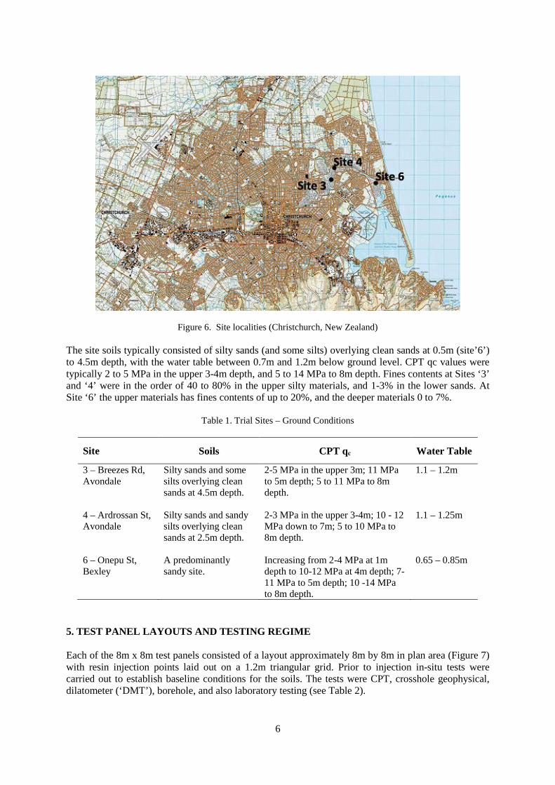
Figure 6. Site localities (Christchurch, New Zealand)
The site soils typically consisted of silty sands (and some silts) overlying clean sands at 0.5m (site’6’) to 4.5m depth, with the water table between 0.7m and 1.2m below ground level. CPT qc values were typically 2 to 5 MPa in the upper 3-4m depth, and 5 to 14 MPa to 8m depth. Fines contents at Sites ‘3’ and ‘4’ were in the order of 40 to 80% in the upper silty materials, and 1-3% in the lower sands. At Site ‘6’ the upper materials has fines contents of up to 20%, and the deeper materials 0 to 7%.
Table 1. Trial Sites – Ground Conditions
Site Soils CPT qc Water Table
3 – Breezes Rd, Avondale
Silty sands and some silts overlying clean sands at 4.5m depth.
2-5 MPa in the upper 3m; 11 MPa to 5m depth; 5 to 11 MPa to 8m depth.
1.1 – 1.2m
4 – Ardrossan St, Avondale
Silty sands and sandy silts overlying clean sands at 2.5m depth.
2-3 MPa in the upper 3-4m; 10 - 12 MPa down to 7m; 5 to 10 MPa to 8m depth.
1.1 – 1.25m
6 – Onepu St, Bexley
A predominantly sandy site.
Increasing from 2-4 MPa at 1m depth to 10-12 MPa at 4m depth; 7-11 MPa to 5m depth; 10 -14 MPa to 8m depth.
0.65 – 0.85m
5. TEST PANEL LAYOUTS AND TESTING REGIME Each of the 8m x 8m test panels consisted of a layout approximately 8m by 8m in plan area (Figure 7) with resin injection points laid out on a 1.2m triangular grid. Prior to injection in-situ tests were carried out to establish baseline conditions for the soils. The tests were CPT, crosshole geophysical, dilatometer (‘DMT’), borehole, and also laboratory testing (see Table 2).

7
Figure 7. Site 4 installation and testing layout
Table 2. Pre- and post-injection testing schedule
Test Number carried out at each panel Pre-injection Post-Injection
CPT 4 7 Cross Hole geophysical tests (Vs, Vp) 2 4 Dilatometer tests 2 2 Plate Load tests 2 2 Borehole 1 - Fines Content Lab test 3-4 - Plasticity Index Lab test 0-2 -
After the pre-injection testing was complete, plywood was laid over the ground (over a layer of compacted gravels) and then concrete blocks were laid to give a 14 kPa general surcharge load. Welded steel plate was placed over the blocks to give a relatively stable working platform. Additional blocks were then laid to superimpose a 28 kPa strip footing load. Pilot holes were drilled and cored through the steel plate, concrete blocks, and plywood to allow the installation of the grout tubes into the ground. The surcharge loads were selected to model both a 2-level unreinforced masonry building (‘URM’), as well as a ‘supermarket’ type commercial building. In each case an assumed 10 kPa floor load was used. The concrete blocks along with an additional 28 kPa ‘footing’ strip load yielded results generally in the mid-range of those for the modelled buildings.

8
Figure 8. Aerial view of trial panel resin injection
The ground was then treated with injected resin by first applying a ‘capping layer’ and then injecting from 6m depth on a ’bottom up’ basis. After a period of at least 2 weeks the concrete blocks were removed, and post injection CPT, Vs/Vp and DMT testing was carried out. One of the spacing trial panels was also partially exhumed to expose the resin veins in the ground (see Figure 1 in section 2). Some ground heave was observed, averaging 40 – 70mm across the three sites, with 70% of this occurring during the injection of the capping layer in the upper 1 – 1.5m of the ground profile. When applied to cleared sites, ground disturbance using resin injection is considerably less than that for other technologies such as stone columns or driven piles. In cases where a building also requires level correction, ground heave will be beneficial. In other cases, allowances will need to be made so that the building can accommodate some changes in final floor level. For heavy buildings, or on sites where the soils being treated are below 2m depth, significant ground heave may not occur at all. 6. RESULTS There is a clear trend of increased soil densities and stiffness. CPT qc increased in the range of 4-12 MPa. (in the order of 5 MPa at sites 3 and 4, and 10 MPa at site 6). This gave an increase in qc1ncs of approximately 50 atm at sites 3&4 and 100 atm at site 6. Shear wave velocities (Vs) increased in the order of 50 -75 m/s at sites 3&4, and 75-100 m/s at site 6. Dilatometer testing showed an increase in horizontal stress index KD of 50 to 75% at sites 3 and 4, and 150% at site 6. From plate load tests, Modulus of Subgrade Reaction (ksb) increased 50 to 90%.
Table 3 Averaged increases in parameters within the treatment zones
The results for site 3 and 6 are presented below (site 4 results were similar to site 3 and have been omitted here).
Site qc qc1Ncs DR Vs KD Ksb 3 88% 68% 32% 35% 47% 57% 4 81% 64% 34% 43% 74% 90% 6 101% 76% 27% 51% 150% 52%
9
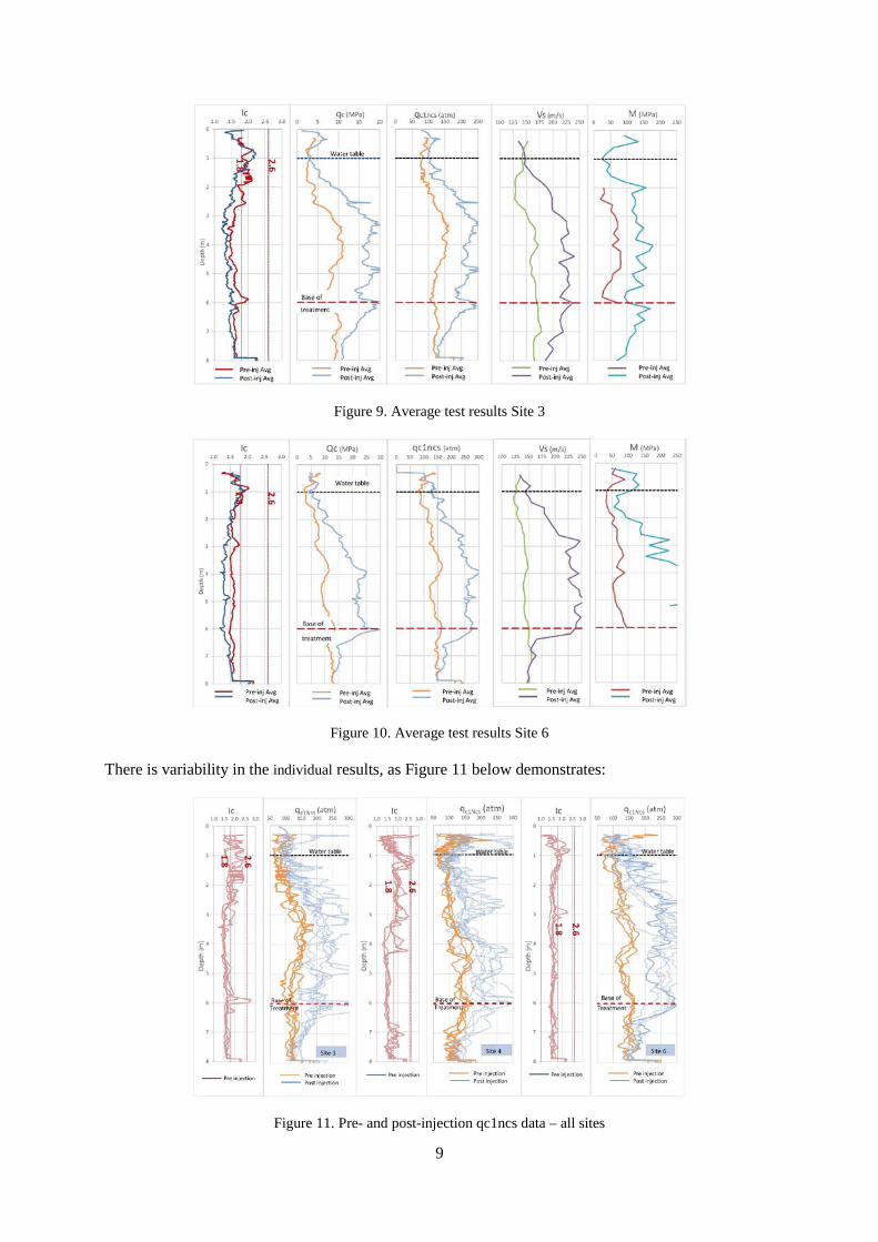
Figure 9. Average test results Site 3
Figure 10. Average test results Site 6 There is variability in the individual results, as Figure 11 below demonstrates:
Figure 11. Pre- and post-injection qc1ncs data – all sites

10
7. CALCULATED POST-LIQUEFACTION SETTLEMENTS The CPT data was analysed for liquefaction triggering potential using the method of Boulanger and Idriss (2014), with free-field settlements computed using Zhang et al. (2002). Not surprisingly, given the increase in qc values measured, considerable reductions in free-field settlements are indicated. In Figures 12 and 13 below a selection of design return period events for Christchurch are highlighted. At the 25-year return period there is a 90% reduction in settlements; as the return period rises to 500 years this reduction is still over 70%. Again, only the results for site 3 and site 6 are presented below.
Figure 12. Calculated settlements pre- and post-improvement (Site 3)
Figure 13. Calculated settlements pre- and post-improvement (Site 6)
8. CALCULATED POST-LIQUEFACTION SEVERITY NUMBER (LSN) Liquefaction Severity Number (LSN) is a depth weighted index that can give an indication of the degree of surface land damage that can result from liquefaction. (van Ballegooy et al 2014). This index is now commonly used increasingly to help assess the possible effects of liquefaction. For each site, post-liquefaction LSN values were calculated across a range of input PGAs (at a magnitude of M7.5). As with calculated settlements, LSN values show an obvious trend of a reduction in LSN across all three sites. The results for sites 3 and 6 are shown below in figures 14 and 15.

11
Figure 14. Calculated LSN pre- and post-improvement (Site 3)
Figure 15. Calculated LSN pre- and post-improvement (Site 6) 9. SUMMARY The ground at all three sites in the study has responded well to resin injection. CPT cone resistance has increased on average 80 - 100%, resulting in an average increase in qc1ncs in the order of 65 - 75%. Calculated liquefaction free field settlements, and LSN have reduced by 50 – 80%. The implied surface damage potential for these sites from seismic liquefaction has therefore reduced dramatically. Given increases in CPT qc, static bearing capacities for shallow foundations have necessarily increased (in the order of 20 – 75%), and static settlements decreased (15 – 60%) at the subject sites (Schmertmann (1978, 1970)). Measured cross-hole shear wave velocities (Vs) have increased in the order of 40%, resulting in soil shear stiffness approximately doubling. Dilatometer testing (DMT) indicates increases in horizontal stress index KD of 50 to 150%. From plate load tests, Modulus of Subgrade Reaction (ksb) has increased 50 to 90%.

12
10. CONCLUSIONS
This study (Traylen, 2017), as well as recent applications in commercial environments, have demonstrated significant increases in soil density and stiffness resulting from the use of resin injection. This shows that resin injection can be an effective ground improvement method for the mitigation of liquefaction potential, and is also potentially useful for other applications where ground densification is required.
The method is particularly applicable in sandy soils (including the siltier sands – e.g., sandy soils with CPT IC values up to about 2.0). It has been noted that decreasing fines content, and increasing confining pressures, lead to better densification effects in treated soils.
The resin injection methodology can be successfully applied for liquefaction mitigation or bearing capacity enhancement to cleared sites as well as to ground beneath existing buildings, structures, and infrastructure assets (for which there are currently few viable options), often with minimal disruption to the use of those assets. 11. ACKNOWLEDGEMENTS This research project was jointly funded by Mainmark Ground Engineering (NZ) Ltd, EQC and MBIE (Ministry of Business, Innovation and Employment). Mainmark also provided all equipment, materials, and site management for the project. We thank all parties for providing both the research funding, as well as the data for this paper. 12. REFERENCES Boulanger, R.W., Idriss, I.M. (2014). CPT and SPT based liquefaction triggering procedures. Report No UCD/CGM-14/01 Dept of Civil & Environmental Engineering, College of Engineering, University of California at Davis.
Erdemgil, M., Saglam, S., Bakir, B. 2007. Utilization of highly expansive polymer injection to mitigate seismic foundation failure for existing structures. Proc. 8th Pacific Conference on Earthquake Engineering.
EQC (in prep). Ground improvement trials report.
Hnat, H., Traylen, N., Wentz, R, van Ballegooy, S. (2017). Resin injection for seismic liquefaction mitigation beneath existing commercial buildings in Christchurch. NZSEE Conference 27-29 April 2017, Wellington NZ.
Schmertmann, J.H. (1970). Static cone to compute static settlement over sand. Journal of Soil Mechanics and Foundation Design, ASCE, Vol 96, SM3.
Schmertmann, J.H. (1978). Guidelines for Cone Penetration Test: Performance and Design. FHWA-TS-78-209 report, US Dept of Transportation.
Traylen, N., van Ballegooy, S., Wentz, R. (2016). Liquefaction mitigation beneath existing structures using polyurethane grout injection. NZSEE Conference 1-3 April 2016 Christchurch NZ.
Traylen, N. (2017). Resin injection ground improvement research trials. Research Report. www.nzgs.org/library/resin-injection-ground-improvement-research-trials/
van Ballegooy, S., Malan, P., Lacrosse, V., Jacka, M., Cubrinovski, M., Bray, J. D., O'Rourke, T. D., Crawford S. A., Cowan, H. (2014). Assessment of liquefaction-induced land damage for residential Christchurch. Earthquake Spectra, February 2014, 30 (1): 31-55.
Zhang, G., Robertson, P., & Brachman, R. (2002). Estimating liquefaction-induced ground settlements from CPT for level ground. Canadian Geotechnical Journal, 39(5): 1168-1180.