tutorial use of physical layer for frequency transport ... · tutorial: use of the physical ......
TRANSCRIPT
Tutorial: Use of the physical layer forTutorial: Use of the physical layer for transporting frequency
Michael MayerNortelISTF 2008, [email protected]
1

PPurpose
• The purpose of the tutorial is to provide an overview of frequency distribution based on physical layer mechanisms such as SDH and Synchronous Ethernetmechanisms such as SDH and Synchronous Ethernet.
• Network aspects are briefly reviewed to understand the use of SSM and how Synchronous Ethernet standardsuse of SSM and how Synchronous Ethernet standards have been developed.
• The fit of Physical layer synchronization in the evolving• The fit of Physical layer synchronization in the evolving network will also be briefly discussed.
© 2008 Nortel Networks. All Rights Reserved2
O tliOutline
• Frequency distribution in telecom networks
• Clock recovery and frequency transfery q y
• Physical layer impairments
• SDH based frequency distribution including SSM• SDH based frequency distribution including SSM
• Synchronous Ethernet
• Next generation frequency distribution
• Summaryy
© 2008 Nortel Networks. All Rights Reserved3

Frequency distribution in Telecom networksnetworks
4

Frequency distribution in telecom t knetworks
St bl f i f d t l t f t l• Stable frequency is a fundamental component of telecom infrastructure.
St bl f i i d t t b i• Stable frequency is necessary in order to meet basic service performance needs, for example:• Slip performanceSlip performance• Control Jitter due to SDH pointers• Air interface requirementsq
• Network maintained synchronization between “nodes” via a dedicated network.• Historically PDH based - Timing between nodes carried over
E1/DS-1 links as a client of the transport networkSTM N b d ith i t d ti f SDH
© 2008 Nortel Networks. All Rights Reserved5
• STM-N based with introduction of SDH• Current OTN: PDH based again.

Cl k hi hClock hierarchy
• Frequency distribution follows a hierarchy• PRC (G.811, Relative cost: €€€)
PRC
SSU• Transit node (G.812, Relative cost: €€)• Local node (G.812, Relative cost: €€)
SDH NE (G 813 Relative cost: €)
SSU1
• SDH NE (G.813, Relative cost: €)
• Clock “trail” resultsSSU10
• Limited number of clocks• Wander will accumulate to some extent
SEC #1
• Reliability• Limit: 60 nodes (See G.803). Much less in practice
SEC #18
SEC #19
© 2008 Nortel Networks. All Rights Reserved6

G 803 di t ib ti ithi dG.803 distribution within a node
SDHSDHNetwor
Node
Network
Element
Clock
Network
Element
Clock
Synchronization
a)a)
Nodeboundary
Clock
SDHNetworSDH
N t
yLink
a)a)
kEleme
ntClock
Network
Element
Clock
a) Timing only
Distribution to Other G.813 Clocks outside the node
© 2008 Nortel Networks. All Rights Reserved7
) g y
Cl k fClock performance
• Placement in the chain will control overall wander under ideal and “failure” conditions
• Factors:• Free-run accuracy• Bandwidth• Holdover performance
• Intent is to meet end-to-end service requirements
© 2008 Nortel Networks. All Rights Reserved8

H ld ti f NE l kHoldover properties of NE clocks
H ld i tHoldover requirements
1.E+07
1.E+08
G 813 O t 1 (f ll t )
1.E+04
1.E+05
1.E+06
erro
r (nS
) G.813 Opt. 1 (full temp)
G.813 Opt.1 (Const.temp)G 812 Type IV (Full temp)
1.E+01
1.E+02
1.E+03
Phas
e G.812 Type IV (Full temp)
G.812 Type IV (Const.temp)
1.E+000.1 1 10 100 1000 10000
Time (seconds)
G.813 Option 1 and G.812 Type IV form the basis for l k d i S h Eth t t k
© 2008 Nortel Networks. All Rights Reserved9
clocks used in Synchronous Ethernet networks

G 803 hi hi l di t ib tiG.803 hierarchical distribution
G.811
PRC
G.812
G.8122
Nodeclock
2Nodeclock
G.812
N d
G.812
N d
G.812
N d
G.812
N dNodeclock
Nodeclock
Nodeclock
Nodeclock
PRC Primary Reference clock
Ref: G.803
© 2008 Nortel Networks. All Rights Reserved10
Clock recovery basicsClock recovery basics
11

Ph i l l l b k dPhysical layer: general background
• Understanding physical transport: How are bits on a wire sent?
osc
1
Fin
Transmitter1011001001 1
0
© 2008 Nortel Networks. All Rights Reserved12

Background: transmission and diencoding
1Data
(“on the wire”)0
( )
Oscillator
• Oscillator in transmitter is used to clock data out of a buffer.
• Oscillator rising edges (in this example) are shown to represent the• Oscillator rising edges (in this example) are shown to represent the transitions of on the wire.
• Spectrum of data will contain component of the clock
© 2008 Nortel Networks. All Rights Reserved13
• Above shows ideal clock. Any jitter on clock will be jitter on pulse stream
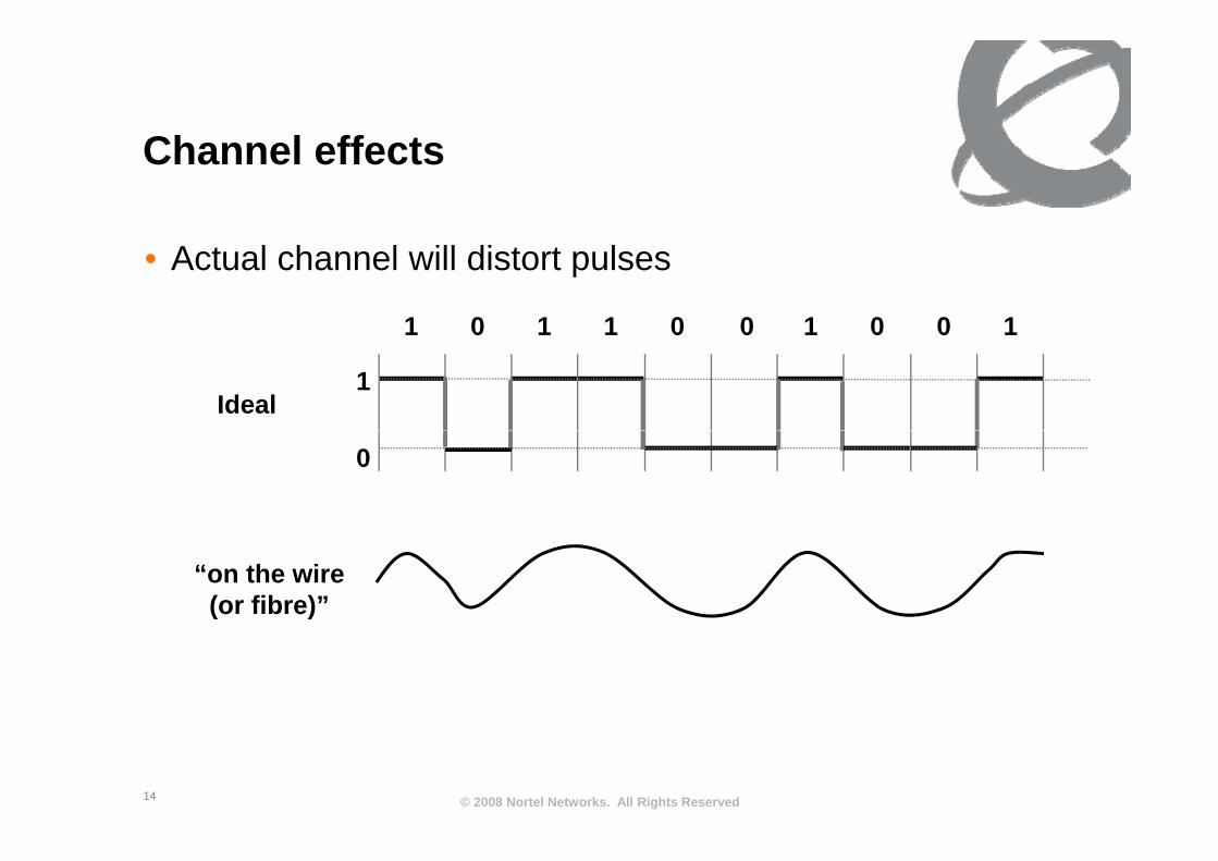
Ch l ff tChannel effects
• Actual channel will distort pulses
1 1 1 1 10 0 0 0 0
1Ideal
1 1 1 1 10 0 0 0 0
0
“on the wire(or fibre)”
© 2008 Nortel Networks. All Rights Reserved14
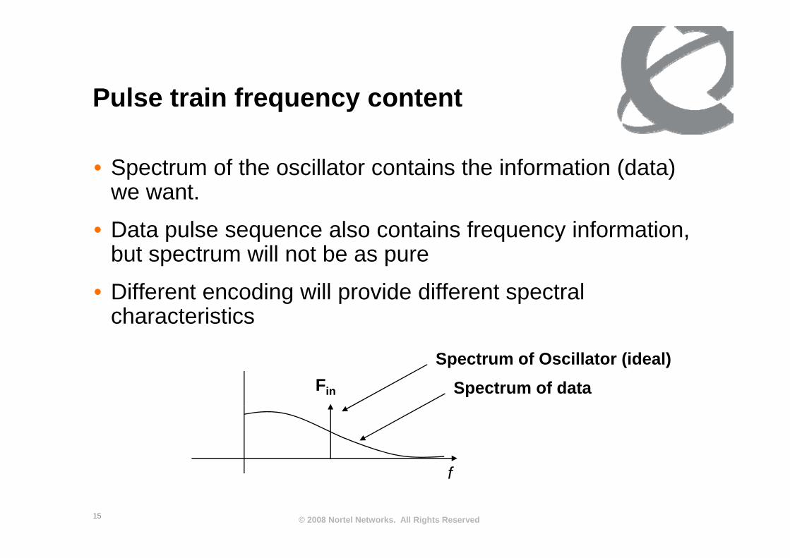
P l t i f t tPulse train frequency content
• Spectrum of the oscillator contains the information (data) we want.
• Data pulse sequence also contains frequency information, but spectrum will not be as pure
• Different encoding will provide different spectral characteristics
Fin
Spectrum of Oscillator (ideal)Spectrum of data
f
© 2008 Nortel Networks. All Rights Reserved15
f
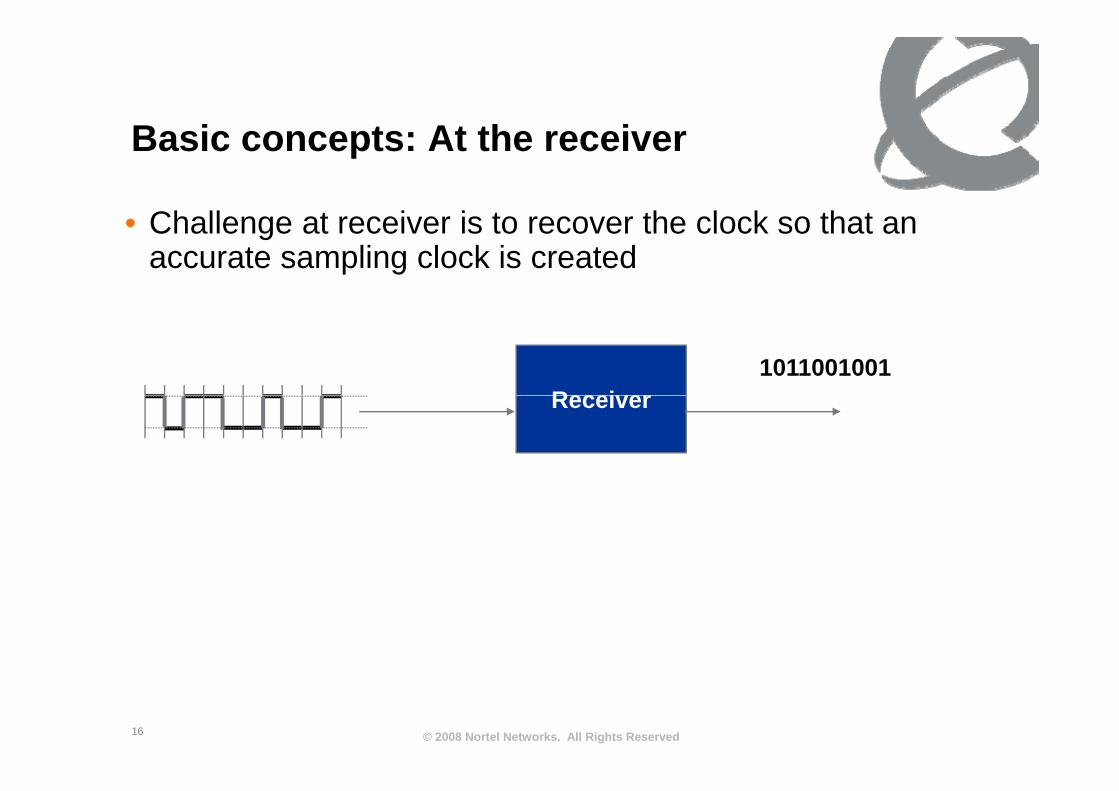
B i t At th iBasic concepts: At the receiver
Ch ll t i i t th l k th t• Challenge at receiver is to recover the clock so that an accurate sampling clock is created
Receiver1011001001
Receiver
© 2008 Nortel Networks. All Rights Reserved16

R i d t il ( i lifi d)Receiver detail (simplified)
ClockRecovery
Pulse shaping(Equalization)
Bit stream DecisionCircuit Data(Equalization) Circuit
Accurate clock recovery is necessary to properly decode the data
© 2008 Nortel Networks. All Rights Reserved17
Accurate clock recovery is necessary to properly decode the data

N id l l t iNon-ideal pulse train
• Channel is non-ideal and subject to noise/distortion
• Recall: Eye Diagram provides limits on pulse shape.y g p p p
Clock recovery aims toClock recovery aims to provide accurate sample point
Instability of clock recovery leads to bit errors
© 2008 Nortel Networks. All Rights Reserved18

R d l kRecovered clock
1 1 1 1 10 0 0 0 0
1Data
(“on the wire”)Data signal
(“on the wire”)0
( )
CDROutput
© 2008 Nortel Networks. All Rights Reserved19

E d t dEnd-to-end
• All transmitter receiver pairs have the transmit clock at the• All transmitter receiver pairs have the transmit clock at the receiver
• To achieve network distribution of frequency:• To achieve network distribution of frequency:• Drive the transmitter• Distribute the recovered clock
T R D TXSSUNetwork Timing path
Tx Rx
CDR
D TxXSSU
SSUCDR
X
© 2008 Nortel Networks. All Rights Reserved20
X “fabric”
Comparison of different modulation hschemes
• NRZ. • Not the best for spectral content• Long strings of identical characters impact clock recovery• Mitigate with scrambling
• Other types of encoding have differing spectra• AMI,
CMI• CMI• QPSK
C l i d l i h i i• Conclusion: modulation scheme is an important aspect to clock recovery but this is not an issue at network sync layer.
© 2008 Nortel Networks. All Rights Reserved21
layer.

Oth tOther aspects
• Other aspects that are often associated with physical layer synchronization • PDH mapping of client into a higher rate transport mechanismPDH mapping of client into a higher rate transport mechanism• Mapping designed to be transparent
• Accommodating clientsg• IPG,• Pointers
St ff bit• Stuff bits
• All are part of “Sync”, but independent of Physical layer sync as discussed so far
• Async transport: bursts of data• Start bits train the clock.
© 2008 Nortel Networks. All Rights Reserved22
• Not used in network timing distribution

Physical layer impairmentsPhysical layer impairments
23

Ph i l l i i tPhysical layer impairments
• Main impairment is noise on the recovered clock
• Network performance is impacted by accumulation of noise in the form of jitter and wanderof jitter and wander.• Jitter (high frequency) is due to phase noise• Wander is due to drift and environmental factors.
• Impairments impact the architecture
Ideal
© 2008 Nortel Networks. All Rights Reserved24
Ideal “noise”

Ch t i ti f iCharacteristic of noise
• Frequency instability is characterized in terms of phase noise, normalized to a 1 Hz bandwidth.
E d di /H (dBH ) f ti f f• Expressed as radians/Hz (dBHz) as a function of frequency
Phase noise characteristicsNoise den
Phase noise characteristics-frequency offset from “carrier”-approximated by several linear sections-log-logsity (log sca
log log-jitter/wander: integrate over frequency to get RMS.-Very low frequency wander is not phaseale)
y q y pnoise, but drift.
© 2008 Nortel Networks. All Rights Reserved25
Frequency (log scale)

F t iFrequency metrics
• Main metrics in Telecom• Wander: MTIE and TDEV• Jitter: Unit Interval (UI) Peak-Peak and RMS
• Jitter/wander demarcation• Wander: noise measured with a 10Hz low pass filter• Jitter: noise measured with a high pass filter. Bandwidth is
depending on ratedepending on rate.
• Clock parametersBandwidth• Bandwidth
• Tolerance (jitter and wander)• Noise generation (jitter and wander)
© 2008 Nortel Networks. All Rights Reserved26
Noise generation (jitter and wander)
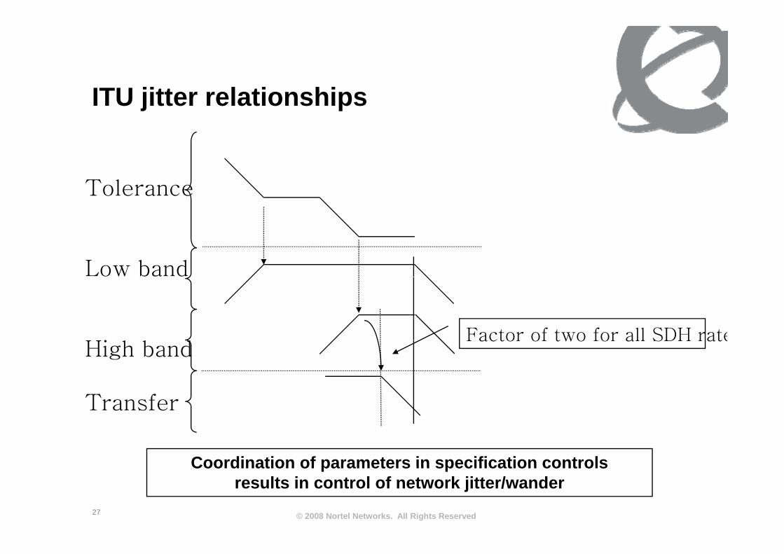
ITU jitt l ti hiITU jitter relationships
Tolerance
Low band
Factor of two for all SDH rateHigh band
Transfer
Factor of two for all SDH rate
Transfer
0.020 80 MHz84Coordination of parameters in specification controls
© 2008 Nortel Networks. All Rights Reserved27
Coordination of parameters in specification controls results in control of network jitter/wander

Jitter and wander are related (of !)course!)
• Specifications for jitter and wander are separate but theySpecifications for jitter and wander are separate, but they are simply measurements of the same signal under different measurement conditions (measurement b d idth)bandwidth)
• Interface specifications (tolerance):
10
4
5
Wander Jitter
10
10
3
4
)
UIpp
15
1.5
10
10
1
2
1 x 10 -11 asymptote
MTI
E (n
s)
0.15
© 2008 Nortel Networks. All Rights Reserved28
10 10 10 10 10 10 10 10 10-2 -1 0 1 2 3 4 5 6
10 0
10 7
Observation time (s)
Frequency (Hz)

C bi d jitt / dCombined jitter/wander10
5 JitterWander
10
10
3
4
UIp 15
Jitter
10
10
10
0
1
2
1 x 10 -11 asymptote
MTI
E (n
s)
pp 1.50.15
1 E+05I)
10 10 10 10 10 10 10 10 10-2 -1 0 1 2 3 4 5 6 10 7
Observation time (s)
Frequency (Hz)
1.E+02
1.E+03
1.E+04
1.E+05
e Am
plitu
de (U
I
1.E-01
1.E+00
1.E+01
1.E-05 1.E-03 1.E-01 1.E+01 1.E+03 1.E+05 1.E+07 1.E+09
Pk-
Pk
Pha
se
© 2008 Nortel Networks. All Rights Reserved29
Frequency (Hz)

Ph N i d Td l t dPhase Noise and Tdev are related• Aside: TDev is a common metric used in sync
measurements to characterize wander
• Tdev is related to phase noise (power spectral density)• Ref. T1.101.1999
• Noise accumulation discussion that follows is based on PSD/phase noise, but principles apply to both jitter and wander
Noise den
Tdev
Frequency (log scale)
nsity (log sc Observation time (log scale)
v (nS)
© 2008 Nortel Networks. All Rights Reserved30
Frequency (log scale)cale)

I i t l tiImpairment accumulation
• The fundamental building block in synchronization are the clocks. (PLL)
T itt / i / l k b d l d i• Transmitter/receiver/clock recovery can be modeled using second order PLL.
• Good place to start to look at impact of impairmentsGood p ace to sta t to oo at pact o pa e ts
F F+ VCO
1/N
FinFout
1/N
Fout =N*Fin
© 2008 Nortel Networks. All Rights Reserved31

N i t ib tiNoise contributions
Φosc Φout /Φin : Low pass filter function
PLL Noise model Transfer function characteristic
Φin Φout+ Φout /Φosc : high pass filter function
• Total noise is the input noise plus noise due to the oscillator.
• Loop bandwidth defines contribution of input and internal inoise
• Input noise is low pass filtered• Internal oscillator noise is high pass filtered
© 2008 Nortel Networks. All Rights Reserved32
• Internal oscillator noise is high pass filtered

Jitt / d l tiJitter/wander accumulation
• Jitter and wander accumulation is typically simulated• Wander: chain of clocks• Jitter: chain of regenerators
Φ Φ Φ
Φin
Φout1
Φosc
+
Φosc
+Φout2 ΦoutN
Φosc
+
© 2008 Nortel Networks. All Rights Reserved33
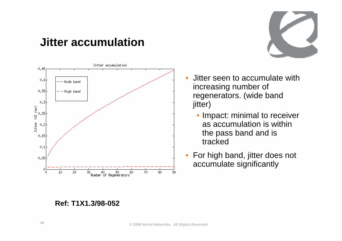
Jitt l tiJitter accumulation
• Jitter seen to accumulate with increasing number of
t ( id b dregenerators. (wide band jitter)• Impact: minimal to receiver
as accumulation is within the pass band and is tracked
• For high band, jitter does not accumulate significantly
Ref: T1X1 3/98 052
© 2008 Nortel Networks. All Rights Reserved34
Ref: T1X1.3/98-052

W d A l tiWander Accumulation• Wander accumulates in a similar
manner to jitter.
• Example shows low frequency phase increasing as a function ofphase increasing as a function of network elements
• G.813 Option 2 clock shown,• Option 2: 0.1 Hz bandwidth• Impact of pass band clearly
seenseen.• Performance representative of
Ethernet EEC2 clock
• Option 1/EEC behavior would be similar (different break points due to different bandwith.
© 2008 Nortel Networks. All Rights Reserved35
Ref: T1.105.09

Cl k b d idth t ti f SDHClock bandwidth: two options for SDH
f ff• Phase noise filtering effect:• Wider bandwidth
• more input phase noise is passed to output• more input phase noise is passed to output• but will pass less internal oscillator noise to output
• Narrow bandwidth• less input phase noise is passed to output• but will pass more internal oscillator noise to output
• Bandwidth selection is a trade-off
• ITU Recommendations (G.813 and G.813) define output ( ) pnoise requirements consistent with end to end objective of meeting G.822 slip objectives.
© 2008 Nortel Networks. All Rights Reserved36

SDH based frequency distributionSDH based frequency distribution
37
SDH b d f di t ib tiSDH based frequency distribution
• SDH utilizes the line to transfer frequency.• Independent of any payload• Enhance reliability through use of SDH protection
• SDH topologies• Linear, Ring• 1:1, 1+1, various ring protection schemes
• Utilizing SDH creates advantage for sync distribution but also provides opportunities to cause trouble
E l Ri t l• Example: Ring topology
• Synchronous Status Messages (SSM) are a mechanism to utilize the flexibility of the SDH network and maintain
© 2008 Nortel Networks. All Rights Reserved38
utilize the flexibility of the SDH network and maintain reliability of synchronization transport.
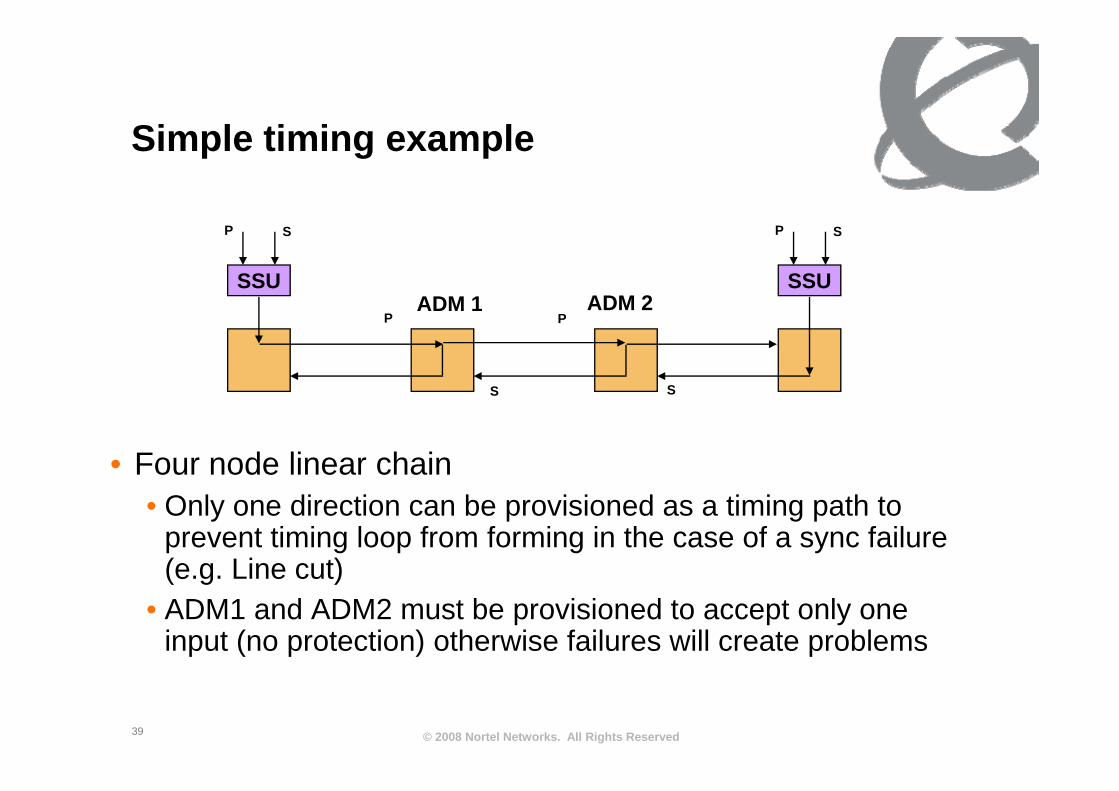
Si l ti i lSimple timing example
ADM 1 ADM 2SSU SSU
P S P S
PADM 1 ADM 2
P
S S
• Four node linear chain
S
• Only one direction can be provisioned as a timing path to prevent timing loop from forming in the case of a sync failure (e g Line cut)(e.g. Line cut)
• ADM1 and ADM2 must be provisioned to accept only one input (no protection) otherwise failures will create problems
© 2008 Nortel Networks. All Rights Reserved39

Failure modes and impactsFailure modes and impacts
ADM 1 ADM 2SSU SSU
P S P STiming Loops:
PADM 1 ADM 2
P
S S
Timing Loop
A timing loop is created when a slave clock receives timing from itselfvia a chain of slaved clocks. (ADM1 switches, creating a timing loop)
S S
P S PHierarchy Violation
Hierarchy Violations
PADM 1 ADM 2
P
SSU SSU Str2
Hierarchy Violation
SEC
Hierarchy Violation occurs when a lower order (lesser precision)S S
© 2008 Nortel Networks. All Rights Reserved40
sync source distributes timing to a higher order BITS.
SONET/SDH Ti i dSONET/SDH Timing modes
• SDH was designed to be an integral part of the frequency• SDH was designed to be an integral part of the frequency distribution network.
• Timing modes• Timing modes• Loop, line, external
• SDH and timing distribution• SDH and timing distribution• Derived DS-1/E1
• Protection• Protection• Holdover: minimize drift during loss of network sync• protection switching to alternate timing sources in the case of p g g
failure (hardware and network)• Synchronization status messages
© 2008 Nortel Networks. All Rights Reserved41
Various modes/protection mechanisms provide network design flexibility
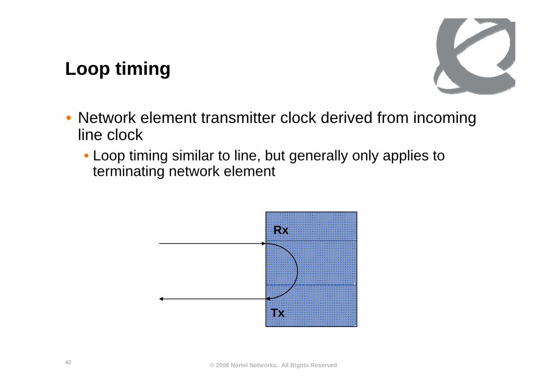
L ti iLoop timing
• Network element transmitter clock derived from incoming line clock
L ti i i il t li b t ll l li t• Loop timing similar to line, but generally only applies to terminating network element
Rx
Tx
© 2008 Nortel Networks. All Rights Reserved42

Li ti iLine timing• Network element derives timing from lineg
• Line timing is similar to line• Received clock derived from line, passes through system clock
O f i t l t bl• One of many receive ports selectable• All transmission ports timed from same clock
Rx Tx
Tx Rx
© 2008 Nortel Networks. All Rights Reserved43
Rx

E t l ti iExternal timing
• Network element derives timing from external sourceg• passes through system clock• Generally two external inputs provided for redundancy (automatically
selected)selected) • All transmission ports timed from same clock• Bit rate may be DS-1, E1, 64kb/s, other
Rx Tx
© 2008 Nortel Networks. All Rights Reserved44
Tx Rx

D i d DS 1/E1Derived DS-1/E1• SONET/SDH is integral part of synchronization distribution• Derived DS-1 provided to provide timing to external network clocks (e.g. SSU,
SASE, SSU)• Frequency of DS-1 is derived from the incoming OCn signal• Bit rate may be DS-1 E1 64kb/s other• Bit rate may be DS-1, E1, 64kb/s, other
• Duplicate ports provided for redundancy, NE may provide some level of switching capability
• Note: Does not necessarily pass through system clock (Filtering/holdover y p g y ( gprovided by SSU)
Rx TxRx Tx
© 2008 Nortel Networks. All Rights Reserved45
RxTx

T i l t l ti i fi tiTypical external timing configuration
BITS/SSUBITS/SSU •BITS provides filtering andprotection to all network element in a single locationM t k lti l i t f•May take multiple inputs from
More than on NE•All outputs from one clockBITS and NE ma ha e d al
Derived outputs integrate withNetwork clocks (SSU)
Rx Tx
•BITS and NE may have dual Clocks, only one will be active
Rx Tx
Tx Rx
© 2008 Nortel Networks. All Rights Reserved46

Ti i lTiming loops• Careful network engineering (provisioning) is required in order to
prevent timing loopsprevent timing loops.• Timing loops will drive clocks to maximum frequency offsets• Example: SSU clock is timing deriving timing from its output
BITS/SSU
Rx Tx Rx Tx
Tx R T R
© 2008 Nortel Networks. All Rights Reserved47
Tx Rx Tx Rx

S h i ti t tSynchronization status messages
• Mechanism within SDH line and Derived outputs to reduce chance of timing loop formation• SSM supported NE
Transmit message in SDH overhead and DS 1 ESF containing quality• Transmit message in SDH overhead and DS-1 ESF containing quality level of clock
• BITS/SSU supporting SSM• Transmit and receive quality on SSM on DS-1 inputs/outputsTransmit and receive quality on SSM on DS 1 inputs/outputs
• BITS/SSU not supporting SSM, but NE supporting SSM• Derived DS-1 switched to AIS to prevent BITS/SSU from tracking
• SSM code indicates holdover quality of clock that is driving aSSM code indicates holdover quality of clock that is driving a synchronization trail• PRC, ST1, ST2, ST3, ST3E, SMC, SEC, etc
• Special code word: DUS
Rx
• Special code word: DUS• Don’t use for synchronization• Reception will prevent timing loops.
DUS
© 2008 Nortel Networks. All Rights Reserved48
Tx
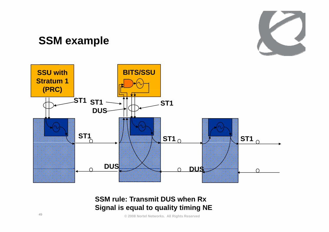
SSM lSSM example
BITS/SSUST1SSU withStratum 1
(PRC)(PRC)
ST1ST1ST1DUS
ST1 ST1 ST1
DUS DUSDUS DUS
© 2008 Nortel Networks. All Rights Reserved49
SSM rule: Transmit DUS when RxSignal is equal to quality timing NE

SSM d f il (SDH)SSM and sync failures (SDH)Step 1: Network FailureStep 4: SSM signaled toS 2 SS SSStep 3: NE reacts to SSU input
BITS/SSUST1SSU withStratum 1
(PRC)
pSignaled on external interface to BITS
Step 4: SSM signaled to downstreamNetwork elements
Step 2: SSU reacts changing SSMStep 3: NE reacts to SSU input
(PRC)
ST1ST1ST1DUS
DUS ST2
ST1 ST1ST2ST1ST2
DUSDUSST2 DUS
© 2008 Nortel Networks. All Rights Reserved50

Synchronous EthernetSynchronous Ethernet.
51
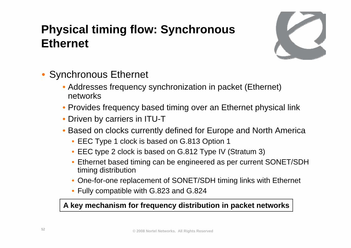
Physical timing flow: Synchronous Eth tEthernet
• Synchronous Ethernet• Addresses frequency synchronization in packet (Ethernet)
networksnetworks• Provides frequency based timing over an Ethernet physical link• Driven by carriers in ITU-T• Based on clocks currently defined for Europe and North America
• EEC Type 1 clock is based on G.813 Option 1• EEC type 2 clock is based on G 812 Type IV (Stratum 3)• EEC type 2 clock is based on G.812 Type IV (Stratum 3)• Ethernet based timing can be engineered as per current SONET/SDH
timing distribution• One for one replacement of SONET/SDH timing links with Ethernet• One-for-one replacement of SONET/SDH timing links with Ethernet• Fully compatible with G.823 and G.824
A key mechanism for frequency distribution in packet networks
© 2008 Nortel Networks. All Rights Reserved52
y q y p
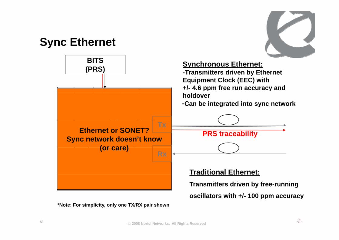
S Eth tSync Ethernet
Synchronous Ethernet:BITS
EEC
Synchronous Ethernet:-Transmitters driven by Ethernet Equipment Clock (EEC) with +/- 4.6 ppm free run accuracy and
(PRS)
EEC(+/- 4.6 ppm)
holdover-Can be integrated into sync network
Tx+/- 100 ppmPRS traceabilitySSM
(IEEE Slow protocol)
Ethernet or SONET?Sync network doesn’t know
(or care)
Tx
Ethernet
Rx
Traditional Ethernet:
( p )(or care)Rx
Switch*Traditional Ethernet:Transmitters driven by free-running
oscillators with +/- 100 ppm accuracy
© 2008 Nortel Networks. All Rights Reserved53
*Note: For simplicity, only one TX/RX pair shown
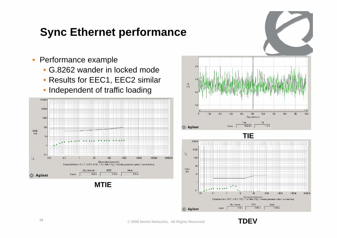
Sync Ethernet performancey p
• Performance example• G.8262 wander in locked mode• Results for EEC1, EEC2 similar• Independent of traffic loadingIndependent of traffic loading
TIE
MTIE
© 2008 Nortel Networks. All Rights Reserved54 TDEV

S Eth t A li tiSync Ethernet Applications
IWF TDMPacket Network
(Packet to TDM)
IWFTDM(TDM to Packet)
IWF TDMPacket Network
(Packet to TDM)
IWFTDM(TDM to Packet)
E E IWF TDMPacket Network
(Packet to TDM)
IWFTDM(TDM to Packet)
IWF TDMPacket Network
(Packet to TDM)
IWFTDM(TDM to Packet)
E E
PRCReference Timing SignalReference Timing Signal
PRCReference Timing SignalReference Timing Signal
• Provide timing to end applications such as TDM/Packet interworking function (IWF)*interworking function (IWF)
• General network timing distribution (SONET replacement)
Wi l b t ti ith Eth t i t f• Wireless base stations with Ethernet interfaces
© 2008 Nortel Networks. All Rights Reserved55
* example is taken from first version of G.8261
S Eth t SSM h iSync Ethernet SSM mechanism
• SSM needed to distinguish Ethernet with PRC traceability from traditional Free-running Ethernet.
• Mechanism debated in standards for ~two years• No dedicated frame with overhead as in SONET• Packet based mechanism needed • Two choices based on IEEE protocols
• CFM (e g Y 1731)• CFM (e.g. Y.1731)• EFM (e.g. 802.3ah link OAM)
• Final protocol selected is 802 3 slow protocol similar to• Final protocol selected is 802.3 slow protocol similar to EFM link based OAM.• Architecturally correct choice
© 2008 Nortel Networks. All Rights Reserved56
y
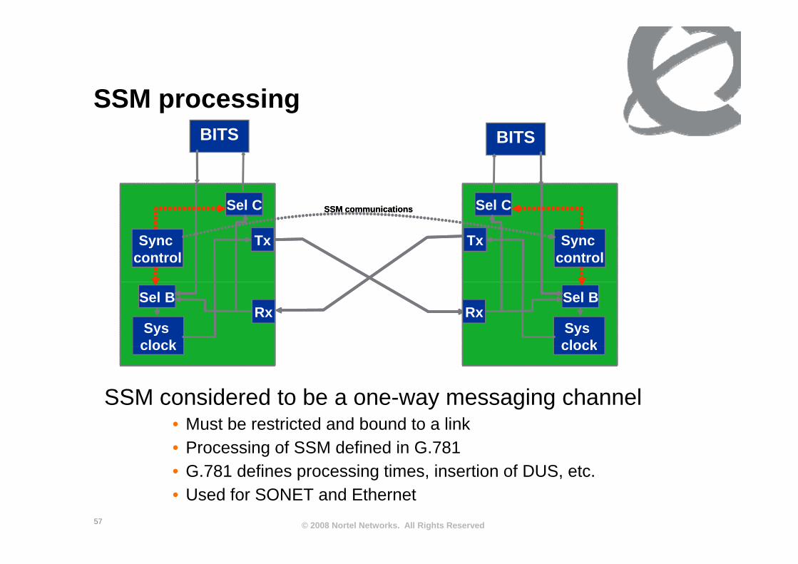
SSM iSSM processingBITSBITS
The image cannot be displayed. Your computer may not have enough memory to open the image, or the image may have been corrupted. Restart your computer, and then open the file again. If the red x still appears, you may have to delete the image and then insert it again.
The image cannot be displayed. Your computer may not have enough memory to open the image, or the image may have been corrupted. Restart your computer, and then open the file again. If the red x still appears, you may have to delete the image and then insert it again.
Sel C
The image cannot be displayed. Your computer may not have enough memory to open the image, or the image may have been corrupted. Restart your computer, and then open the file again. If the red x still appears, you may have to delete the image and then insert it again.
The image cannot be displayed. Your computer may not have enough memory to open the image, or the image may have been corrupted. Restart your computer, and then open the file again. If the red x still appears, you may have to delete the image and then insert it again.
Sel CSSM communications
The image cannot be displayed. Your computer may not have enough memory to open the image, or the image may have been corrupted. Restart your computer, and then open the file again. If the red x still appears, you may have to delete the image and then insert it again.
The image cannot be displayed. Your computer may not have enough memory to open the image, or the image may have been corrupted. Restart your computer, and then open the file again. If the red x still appears, you may have to delete the image and then insert it again.
Sel C
The image cannot be displayed. Your computer may not have enough memory to open the image, or the image may have been corrupted. Restart your computer, and then open the file again. If the red x still appears, you may have to delete the image and then insert it again.
The image cannot be displayed. Your computer may not have enough memory to open the image, or the image may have been corrupted. Restart your computer, and then open the file again. If the red x still appears, you may have to delete the image and then insert it again.
Sel CSSM communications
The image cannot be displayed. Your computer may not have enough memory to open the image, or the image may have been corrupted. Restart your computer, and then open the file again. If the red x still appears, you may have to delete the image and then insert it again.
Sync control
The image cannot be displayed. Your computer may not have enough memory to open the image, or the image may have been corrupted. Restart your computer, and then open the file again. If the red x still appears, you may have to delete the image and then insert it again.
TxThe image cannot be displayed. Your computer may not have enough memory to open the image, or the image may have been corrupted. Restart your computer, and then open the file again. If the red x still appears, you may have to delete the image and then insert it again.
Sync control
The image cannot be displayed. Your computer may not have enough memory to open the image, or the image may have been corrupted. Restart your computer, and then open the file again. If the red x still appears, you may have to delete the image and then insert it again.
Tx
The image cannot be displayed. Your computer may not have enough memory to open the image, or the image may have been corrupted. Restart your computer, and then open the file again. If the red x still appears, you may have to delete the image and then insert it again.
Sys clock
The image cannot be displayed. Your computer may not have enough memory to open the image, or the image may have been corrupted. Restart your computer, and then open the file again. If the red x still appears, you may have to delete the image and then insert it again.
Rx
The image cannot be displayed. Your computer may not have enough memory to open the image, or the image may have been corrupted. Restart your computer, and then open the file again. If the red x still appears, you may have to delete the image and then insert it again.
Sel BThe image cannot be displayed. Your computer may not have enough memory to open the image, or the image may have been corrupted. Restart your computer, and then open the file again. If the red x still appears, you may have to delete the image and then insert it again.
Sys clock
The image cannot be displayed. Your computer may not have enough memory to open the image, or the image may have been corrupted. Restart your computer, and then open the file again. If the red x still appears, you may have to delete the image and then insert it again.
Rx
The image cannot be displayed. Your computer may not have enough memory to open the image, or the image may have been corrupted. Restart your computer, and then open the file again. If the red x still appears, you may have to delete the image and then insert it again.
Sel B
SSM considered to be a one-way messaging channel
clock clockclock clock
• Must be restricted and bound to a link• Processing of SSM defined in G.781• G 781 defines processing times insertion of DUS etc
© 2008 Nortel Networks. All Rights Reserved57
G.781 defines processing times, insertion of DUS, etc.• Used for SONET and Ethernet

S Eth t SSM f t (ESMC)Sync Ethernet SSM format (ESMC)ESMC PDU format
Octet number Size Field
1-6 6 octets Destination Address =01-80-C2-00-00-02 (hex)
7 12 6 octets Source AddressESMC contains
7-12 6 octets Source Address
13-14 2 octets Slow Protocol Ethertype = 88-09 (hex)
15 1 octets Slow Protocol Subtype =0A (hex)
16-18 3 octets ITU-OUI = 00-19-A7 (hex)
SSM codeEEC1: 1011EEC2: 1010
16-18 3 octets ITU-OUI 00-19-A7 (hex)
19-20 2 octets ITU Subtype
21 4 bits Version
1 bit Event flagb ve g
3 bits Reserved
22-24 3 octets Reserved
25-1532 36-1490 Data and Padding
8 bits Type: 0x01
16 bits Length: 0x04
QL TLV
octets
Last 4 4 octets FCS4 bits 0 (unused)
4 bits SSM code
© 2008 Nortel Networks. All Rights Reserved58
Extensions to SSM to be accommodated using TLV mechansims

SSM SDH ESMCSSM: SDH vs ESMC
SDH frameSDH: Frame rate: 8 kbit/sRaw SSM channel: 8 kbit/s
SSMByte
Overhead Payload
PRS DUS DUS
Processing simplyProcessing simplysees a state change
© 2008 Nortel Networks. All Rights Reserved59

SSM SDH ESMCSSM: SDH vs ESMC
• Sync Ethernet SSM based on IEEE 802.3 slow protocol has bandwidth restrictions
• 10 frames/second
• Equivalence to SDH behavior: two message types• Heartbeat (1/Second) and Event(immediate)
PRS PRS DUS DUS
SDH
Event messagetype provides
SDH
accurate statechange
HeartbeatMessage
HeartbeatMessage
~ 1 Sec.
HeartbeatMessage
HeartbeatMessage
EventMessage
HeartbeatMessageEthernet
© 2008 Nortel Networks. All Rights Reserved60
MessageType(PRS)
MessageType(DUS)
MessageType(PRS)
MessageType(PRS)
MessageType(DUS)
MessageType(DUS)

“Next generation frequency distribution”distribution
61

Th F t f F di t ib tiThe Future of Frequency distribution
• Frequency distribution has been critical for the current core network
• Services over the NGN are to be provided ubiquitously over a mixed wire-line/wireless infrastructure.
• Wireless Access infrastructures have critical synchronization needs that include both frequency and time/phasetime/phase.• Currently, phase/time is provided by GPS/GNSS• Concerns have been raised over availability and reliability y y
(antenna, jamming)
• Ethernet based frequency distribution provides
© 2008 Nortel Networks. All Rights Reserved62
q y popportunities to provide frequency in wireless backhaul
Th F t f F di t ib tiThe Future of Frequency distribution
• Industry is also looking at phase/time using packet based methods such as IEEE1588V2 and NTP
St d d l ki t d f h i l b d ti i t• Standards looking towards use of physical based timing to “help” the distribution of time/frequency
• Packet based frequency distribution has advantages in• Packet based frequency distribution has advantages in some situations, but may be prone to packet network impairments• Physical layer synchronization avoids these
© 2008 Nortel Networks. All Rights Reserved63

C t di t ib tiCurrent sync distribution
Sync Status messaging
C GPS
Sync Status messagingon some elements
SDH NE
Cs, GPS(or from line via
derived DS-1)
SDH basedfrequencydistribution
E1/2048 kHzinterfaces from
NEdistributioninterfaces from
BITS to NE
NE
TDM based Network elements
© 2008 Nortel Networks. All Rights Reserved64

Evolving sync network (within an ffi )office)
Sync Status messagingon some elements
C GPS
on some elements(a must for some) Changes/Additions
are indicated in Red italics
TimingDistribution NE
Cs, GPSWhat about line
From Packet NE?Distribution
SDH/Ethernetbased frequencydistribution
Frequency,Time,
P ibl Ph NEdistributionPossibly Phase
TDM/PacketNetwork elementsPacket
NEWireless
NEAccess
NE
© 2008 Nortel Networks. All Rights Reserved65
NENE NE
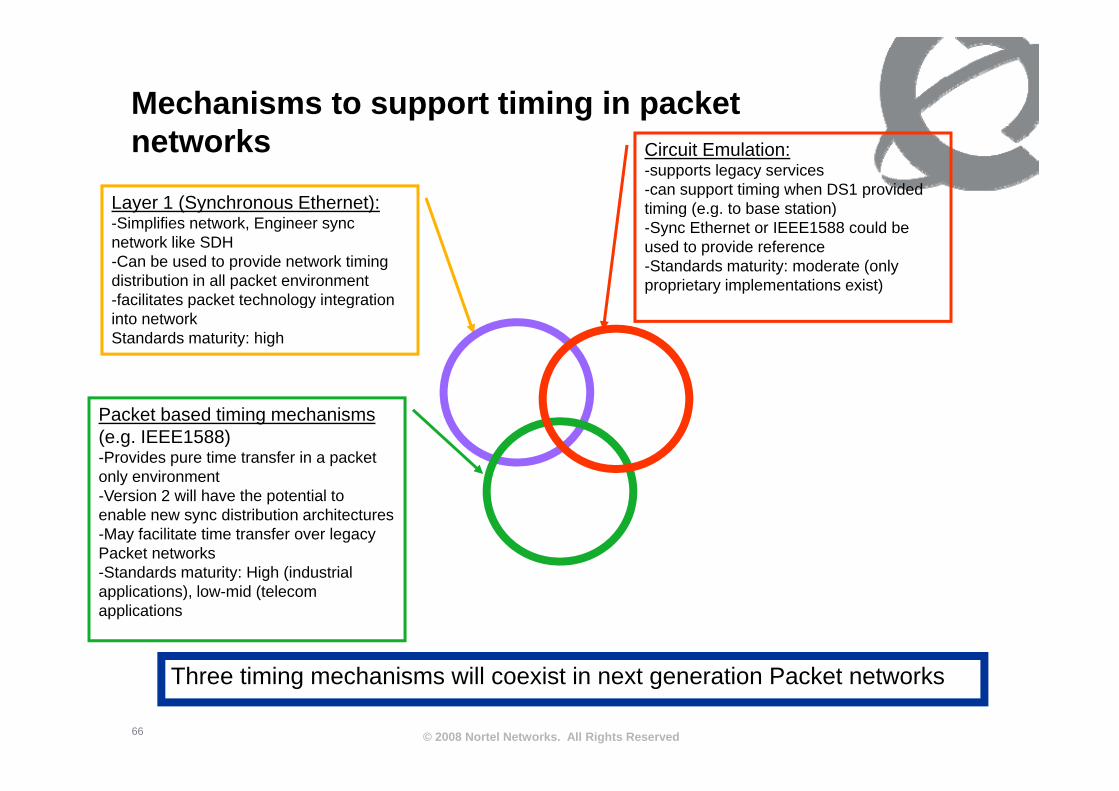
Mechanisms to support timing in packet networks Circuit Emulation:
-supports legacy services-can support timing when DS1 provided timing (e.g. to base station)Layer 1 (Synchronous Ethernet): g ( g )-Sync Ethernet or IEEE1588 could be used to provide reference-Standards maturity: moderate (only proprietary implementations exist)
-Simplifies network, Engineer sync network like SDH-Can be used to provide network timing distribution in all packet environment-facilitates packet technology integration p gy ginto networkStandards maturity: high
Packet based timing mechanisms(e.g. IEEE1588) -Provides pure time transfer in a packet only environment-Version 2 will have the potential to enable new sync distribution architectures-May facilitate time transfer over legacy Packet networks-Standards maturity: High (industrialStandards maturity: High (industrial applications), low-mid (telecom applications
© 2008 Nortel Networks. All Rights Reserved66
Three timing mechanisms will coexist in next generation Packet networks

SSummary
• Physical layer synchronization separates the timing of the signal from the content (frame)
• Current SDH based synchronization network will remain active for some time, physical synchronization using Ethernet provides a graceful migration pathEthernet provides a graceful migration path• Compatible with existing synchronization deployment rules
and performance
• Physical layer synchronization will co-exist with new packet based frequency/time/phase methods.• Likely see systems that integrate both frequency and time
distribution
© 2008 Nortel Networks. All Rights Reserved67

Q&A