tutorial lab 1(v1.1) behavioral modeling &...
TRANSCRIPT
TI – something from this step needs to be turned in Q – there is a question in the back that refers to this step
Copyright © 1997, Hon-Chi Ng.
Permission to duplicate and distribute this document is herewith granted for sole educational purpose without any commercialadvantage, provided this copyright message is accompanied in all the duplicates distributed. All other rights reserved.
All Cadence’s tools referred are trademarks or registered trademarks of Cadence Design Systems, Inc. All other trademarksbelong to their respective owners.
CPR E 465 LABORATORYTutorial Lab 1(v1.1)
Behavioral Modeling & SimulationWeek 2
(Authored by: Hon-Chi Ng, ECpE Dept, Iowa State University)(Modified by: Charlie Boecker for Cadence v4.4.1)
0. Introduction
In the first part of this lab, you will learn how to create library, cells and cellviews in Cadence'sdesign database called Design Framework II (DFII).
Next, you will learn how to design circuits abstractly through behavioral modeling as well ashierarchically through structural modeling. Behavioral modeling is described throughhardware description language (HDL). Currently, the 2 dominant general-purpose HDLs areVerilog-HDL and VHDL (VHSIC HDL). You will learn one of them, namely Verilog, andsimulate your designs using Cadence's Verilog-XL simulator.
1. Design Management with Design Framework II (DFII)
1.1 Now, let us create a directory called cadence . We will store all our designs of all the labsin the cadence directory
> mkdir ~/cadence> cd cadence
To run Cadence,> cadence &
After a few seconds, a CIW (Command Interpreter Window) should appear. Later, aWelcome to Cadence 4.4.1 dialog box will appear. Along with the Welcome to Cadence4.4.1, a What’s New box will appear. Click on Close button after reading the content of theWelcome to Cadence 4.4.1 box. Then in the What’s New box go to View | Off at Startup…
Cpr E 465 Laboratory: Tutorial Lab 1 (v1.1) ¾ Behavioral Modeling and Simulation Page 2 of 47
Last Updated: 01/11/99 9:54 AM
Click on YES in the Turn off What’s New at Startup window that pops up. This will disablethe display of the box when you log in next time.
As conventions for the rest of this handout and upcoming handouts, LMB stands for leftmouse button. Likewise, MMB and RMB stand for middle mouse button and right mousebutton respectively.
1.2 Cadence keeps all its designs in database format called Design Framework II (DFII). Thetop level organization is called library . Each library has a technology, described in thetechnology file, associated with it. All designs within the library are based on the sametechnology file.
Before we start creating a new design library, let us look at what the default libraries that areavailable. In CIW, choose Tools | Library Manager... In Library Manager window, there aresome libraries supplied as default. Only those libraries prefixed with 465 will be used forour labs, namely 465ref and 465Pads , 465pads12 . We will hereafter refer these libraries asreference libraries. Pay no attention to other libraries.
Let us go to 465ref library by clicking on it using the left mouse button (LMB). We want tosee the different categories available in the library, so we need to click on the ShowCategories button in the Library Manager. You will see a few categories listed under465ref library. Within these categories, there is more sub-categories or cells. For example,Gates category contains sub-categories like ANDs , NANDs , NORs, ORs, XNORs and XORs,and cells like buffer and inv . Within ANDs category, it contains cells like and2 , and3 , and4 ,and5 , and and6 . Each of these cells has 2 different cellviews namely symbol and verilog .
So far, you have been introduced to the terms library, category, cell and cellview. Categoryallows us to organize our designs within a given library. Cell is the actual design. Each cellcan have multiple cellviews, the representations of the design. The analogy is — think oflibrary as user account, category as directory, cell as file, and cellview as format. (I know itis kind of awkward to have a file with multiple formats, but this is the best analogy I canthink of. :^) )
1.3 Now, let us create a library named cpre465 . The technology file we will use is written forMOSIS Orbit 2.0m N-well, double-poly, double-metal CMOS process, which complies withMOSIS SCMOS (Scalable CMOS) Design Rules. Hence, l = 1.0m.
NOTE: All the libraries should be created using File | New | Library... under the CIW,there is also a File | New | Library... command under the Library Manager. If you use the
second method the Library won't be created correctly, so don't use it.
In CIW, choose File | New | Library... In the New Library form, type cpre465 in LibraryName field. The path should be /home/user/cadence . In the Technology File field click onAttach to an existing techfile. Click on OK. An Attach Design Library to Technology File

Cpr E 465 Laboratory: Tutorial Lab 1 (v1.1) ¾ Behavioral Modeling and Simulation Page 3 of 47
Last Updated: 01/11/99 9:54 AM
form should appear. Since we will use the digital version of MOSIS Orbit 2.0 m technology,choose Orbit20digital for the Attach to Technology Library field. Click on OK.
The technology is being attached, and the status is shown in CIW. Upon completion, CIWwill display the message
Created library "cpre465" as "home/user/cadence/cpre465"Design library 'cpre465' successfully attached to technology library
'Orbit20digital'
You will also notice that cpre465 library is now listed within Library Manager windowalong with other reference libraries. Click the left mouse button (LMB) on cpre465 librarywe just created. Nothing is under it yet, but that will definitely change.
2. Concurrency of Hardware & HDL
How does Hardware Description Language (HDL) differ from general programming languages?In another words, why can't general programming languages be used to described digital circuits?Concurrency. Separate parts of a hardware can simultaneously operate either dependently orindependently, whereas a software program flows sequentially. (As a side question, can multi-threading in programming languages address such concurrency of hardware?)
HDL also provides other features/constructs (syntax) to allow designers to describe digitalcircuits more naturally and conveniently.
2.1 Design Concept using Verilog-HDL
Before we learn how to describe designs in behavioral modeling, let us study some conceptsin Verilog.
a) ModuleModule (also referred as block or entity) is the basic unit of a circuit design. It containslogical functionality that is specified internally and exhibited through its inputs andoutputs (port interface) to other modules (external world). By grouping the functionalityinto a module and allowing inter-module communications through port interface, theinternal implementation of the module is hidden, i.e. implementation of the module maybe independently modified without affecting other modules and overall functionality.(Timing and loading issues are ignored here.)
b) InstanceThis may be an initially confusing concept. An instance is the actual object createdbased on a given module, the master. Multiple instances can be created from the samemodule, where they share the same functionality as described by the module, but operate

Cpr E 465 Laboratory: Tutorial Lab 1 (v1.1) ¾ Behavioral Modeling and Simulation Page 4 of 47
Last Updated: 01/11/99 9:54 AM
independently. The analogy to programming is — multiple variables can be declaredfrom the same data type, but each holds its own value of the type declared.
The process of creating an instance from a module is called instantiation. A module isjust a template that defines the functionality. An instance is the actual object used informing the design.
This module-instance concept is similar to object-oriented (OO) paradigm inprogramming. Perhaps, OO paradigm was originally "borrowed" from hardware. :^)
c) PortPort (also referred to as a pin or terminal) is the interface where a module exhibits itsfunctionality, and is the way modules (actually, instances) communicate with each other.A module can have multiple ports or be portless (refer to Step 2.6). A port can be ofeither input, output or bi-directional. A port can also be single-bit or multiple-bit(bus/vector) wide. It is similar to a formal parameter/argument in programming.
2.2 Hierarchy
It would be inefficient and extremely difficult to implement a complex design in a single flatlevel. A more practical approach is to divide the design into small blocks and solve themseparately. These blocks can be further divided within themselves if they are still toocomplex to handle until each block is manageable. Such recursive division is calleddecomposition of hierarchy. Hierarchy allows designers to solve a huge, complex problemusing a divide-and-conquer technique.
The overall design is the highest level within the hierarchy, which is called the top-levelmodule. The lowest level blocks that make up the design are called the leaf cells.Intermediate modules are those besides top-level module and leaf cells within the hierarchy.Figure 2.2 illustrates a typical hierarchy represented as a tree structure.
Figure 2.2: Example of Hierarchy Tree
Leaf
Top-level
Leaf LeafIntermediate
Intermediate
LeafLeaf Leaf

Cpr E 465 Laboratory: Tutorial Lab 1 (v1.1) ¾ Behavioral Modeling and Simulation Page 5 of 47
Last Updated: 01/11/99 9:54 AM
A design can contain an arbitrary number of hierarchial levels, which depends on thecomplexity of the design. The more complex the design is, the more levels of hierarchy itusually needs.
2.3 Design Methodology
There are 2 basic design methodologies, namely top-down and bottom-up.a) Top-down design methodology
In a top-down decomposition approach, we start by defining the top-level block andidentify the sub-blocks necessary to build the top-level block. We further subdivide thesesub-blocks into leaf cells.
When do we stop sub-dividing a new level of hierarchy? There is no obvious rule.Usually, we stop at the level when further subdividing/decomposing the blocks offer nosignificant advantage in reusability and comprehensibility of details.
b) Bottom-up design methodologyIn a bottom-up assembly approach, we begin from the leaf cells. We construct the higherblocks using the leaf cells available to us. We continue building next higher blocks untilthe final design is realized.
In practice, neither approach is used alone. A Hybrid of both approaches is typicallyapplied. We are often given the top-level specification as well as the leaf cells standardlyavailable. The functional architecture is defined top-down whereas the actual circuit isimplemented bottom-up.
2.4 Bit-slicing Technique in Hierarchical Decomposition
Usually, when decomposing a hierarchy, the design is partitioned into several submodulesbased on their functionalities. This is sometimes known as vertical partitioning.
However, for the multi-bit / vector design, there is another approach for partitioning,namely bit-slicing, or sometimes known as horizontal partitioning. Instead of partitioningbased on functionalities, the multi-bit design is decomposed into multiple identical single-bit design. Bit-slice technique enhances the scalability of the design, and increasesreusability, particularly in wide-vector (32 bit or more) design.
2.5 Levels of Modeling Abstraction
This is the most interesting and subjective notion in HDL. Different books/authors havedifferent perspectives on categorizing the levels of modeling abstraction. My personal viewis — the lines between the levels are blurry, especially given that hybrid/mixed-modemodeling abstraction exists.

Cpr E 465 Laboratory: Tutorial Lab 1 (v1.1) ¾ Behavioral Modeling and Simulation Page 6 of 47
Last Updated: 01/11/99 9:54 AM
Some books, particularly older ones, define only 2 levels, namely behavioral andstructural . Other levels defined are dataflow, RTL , block-level, logic-level, gate-leveland switch-level. The following is how I view and define these levels.
a) BehavioralThis is the highest level of abstraction. Functionality is expressed by an algorithmicdescription that resembles programming languages. Timing and loading are usuallyignored at this very abstract level.
b) Dataflow & RTLIt is the next lower level of abstraction below behavioral. Dataflow and RTL (registertransfer level) are of the same modeling abstraction. However, some books consider RTLas the combination of dataflow and behavioral levels (or more precise, synthesizablebehavioral level).
This level mostly describes synchronous design, which is how all complex digitalcircuits behave, The major components described are finite-state control logic,datapath, and registers. All events take place in reference to clock edges of single ormore reference clocks.
When logic synthesis is discussed, the term RTL is more commonly used. RTL iscurrently the highest level of abstraction that can be practically/efficiently synthesizedinto lower level of abstraction. Hence, RTL is frequently referred as synthesizabledescription. Prior to era of logic synthesis, this level was treated as part of behaviorallevel modeling abstraction.
c) StructuralThis is the level that describes hierarchy. Structural modeling is always part of anymixed-mode modeling because its hierarchical characteristic allows different modelingabstractions to be "glued" within a tree structure. It is the general term that encapsulatesblock-level, logic-level, gate-level and switch-level because all of them are based onhierarchy except with different depth of implementation details. In fact, some leaf cellswithin the hierarchy may also contain behavioral or dataflow modeling.
A pure structural design should consist only component instantiations at all the higherlevels of its hierarchy except the leaf cells. Only the leaf cells can be of any other levelsof modeling abstractions. However, sometimes the term pure structural excludesbehavioral or dataflow to be even at the leaf cells.
d) Block-level & Logic-levelBoth block-level and logic-level are the description of design based on functional logicblocks. Functional logic blocks can comprised of other smaller functional logic blocks orprimitive logic gates. However, some uses block-level to refer design of LSI (large scaleintegration) and logic-level for MSI (medium scale integration).
e) Gate-level
Cpr E 465 Laboratory: Tutorial Lab 1 (v1.1) ¾ Behavioral Modeling and Simulation Page 7 of 47
Last Updated: 01/11/99 9:54 AM
Design at this level is described in term of primitive gates, namely AND, OR and NOT.This is the lowest level of modeling abstraction that is still independent of transistorlogic to be implemented. Nevertheless, preliminary timing and loading informations canbe estimated at this level of modeling abstraction.
Boolean expressions may vaguely be considered as gate-level since they are based onAND, OR and NOT operations.
Besides AND, OR and NOT gates, Verilog also provides other gate-level primitives, e.g.NAND, NOR, XOR, XNOR, buffer, tristate buffer and tristate inverter.
f) Switch-levelThis is lowest level of modeling abstract that can be described in Verilog. In fact, not allHDLs have this level of modeling — VHDL does not. This is also known as transistor-level modeling abstraction. However, Verilog only can only model MOS transistors.Hence, the term switch-level, instead of transistor-level, is used to emphasize suchlimitation.
Each MOS transistor is modeled abstractly as a switch. Hence, the basic functionality iseither on or off. This level of modeling abstraction allows designers to more closedescribe the designs to the actual transistor logic, e.g. CMOS, NMOS, pass transistor.With optional attributes in Verilog, description of dynamic CMOS logic is also feasible.Since static CMOS logic is ratioless, switch-level modeling may not sound thatappealing. However, the power of switch-level modeling becomes obvious in describingratio logic (NMOS, pseudo-NMOS), steering logic (pass transistor / transmission-gate)and dynamic logic (dynamic / domino CMOS).
The switch-level primitives in Verilog are unidirectional switches, bidirectional passswitches, tristate bidirectional switches, and resistive switches.
To more accurately model the MOS transistor, Verilog provides additional attributes toswitches. Each switch can have a driving strength associated. In fact, Verilog defines 8different levels of signal strength. In the case of contention, signals with larger drivestrength dominate instead of resulting X state (unknown/don't care). Resistive switchesare used to model MOS transistors with high source-to-drain impedance, where the signalstrengths are reduced when signals pass through.
For charge storage (capacitive) nodes, Verilog provides a special type of net, namelytrireg , to account for such characteristic.
Switch-RC option for Cadence’s Verilog-XL simulator simulates by computing the riseand fall delays based on gate, drain and source capacitances, and the resistive strength ofgiven transistor size, which are specified through transistor technology macro (compilerdirective). Capacitance attribute can be associated onto the trireg net to account forparasitic capacitance on the net.
Cpr E 465 Laboratory: Tutorial Lab 1 (v1.1) ¾ Behavioral Modeling and Simulation Page 8 of 47
Last Updated: 01/11/99 9:54 AM
g) Mixed-mode modelingMixed-mode modeling describes a design with more than one modeling abstraction. Thisis usually achieved using structural modeling and other level of modeling abstraction.
2.6 Test Benches / Test Fixtures / Stimuli / Test vectors
Test benches, test fixtures, stimuli and test vectors all refer to the set of conditionals that arefed to the inputs of a module to verify functionality of the module by examining its outputs.The conventional way is exhaustive verification, which supplies all possible inputs to themodule under test and makes sure the outputs behave as expected. This demands designersto supply all conditions of inputs they can think of. Hence, even if a module passes the setof test vectors/stimuli, it does not necessary infer that the module functions perfectly sincesome cases may be inadvertently missed due to human errors. Such exhaustive test is alsovery time consuming.
Nevertheless, this is the only verification method available until formal verification , asupposedly more robust and efficient method becomes mature and available.
The test bench is a portless module, which instantiates the top-level module and supplies testvectors to the top-level instance using behavioral statements.
3. Behavioral Modeling with Verilog
3.1 Now, we are ready to create our 1st design. We will design a 1-bit inverter, create a cellnamed inverter . I know this is not very exciting, but it is an easy way to get started.;^)
In Library Manager window, select the cpre465 library, by clicking on it in the LibraryManager, in the Library Manager choose File | New | Cell View… In the Create New Fileform, the Library Name should be cpre465. Type inverter in Cell Name field andbehavioral in the View Name field. Change the Tool field to Verilog-Editor and clickon OK.
An editor window with the following content appears.
// Verilog HDL for "cpre465", "inverter" "_behavioral"
module inverter ;
endmodule
By default, your editor is emacs. If emacs is not your favorite, you may change your defaulteditor as explained in Step 2.5 in Preparatory Lab 0.
Cpr E 465 Laboratory: Tutorial Lab 1 (v1.1) ¾ Behavioral Modeling and Simulation Page 9 of 47
Last Updated: 01/11/99 9:54 AM
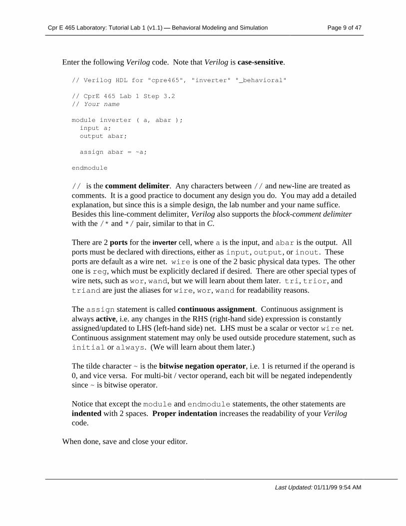
Enter the following Verilog code. Note that Verilog is case-sensitive.
// Verilog HDL for "cpre465", "inverter" "_behavioral"
// CprE 465 Lab 1 Step 3.2// Your name
module inverter ( a, abar ); input a; output abar;
assign abar = ~a;
endmodule
// is the comment delimiter. Any characters between // and new-line are treated ascomments. It is a good practice to document any design you do. You may add a detailedexplanation, but since this is a simple design, the lab number and your name suffice.Besides this line-comment delimiter, Verilog also supports the block-comment delimiterwith the /* and */ pair, similar to that in C.
There are 2 ports for the inverter cell, where a is the input, and abar is the output. Allports must be declared with directions, either as input , output , or inout . Theseports are default as a wire net. wire is one of the 2 basic physical data types. The otherone is reg , which must be explicitly declared if desired. There are other special types ofwire nets, such as wor , wand, but we will learn about them later. tri , trior , andtriand are just the aliases for wire , wor , wand for readability reasons.
The assign statement is called continuous assignment. Continuous assignment isalways active, i.e. any changes in the RHS (right-hand side) expression is constantlyassigned/updated to LHS (left-hand side) net. LHS must be a scalar or vector wire net.Continuous assignment statement may only be used outside procedure statement, such asinitial or always . (We will learn about them later.)
The tilde character ~ is the bitwise negation operator, i.e. 1 is returned if the operand is0, and vice versa. For multi-bit / vector operand, each bit will be negated independentlysince ~ is bitwise operator.
Notice that except the module and endmodule statements, the other statements areindented with 2 spaces. Proper indentation increases the readability of your Verilogcode.
When done, save and close your editor.
Cpr E 465 Laboratory: Tutorial Lab 1 (v1.1) ¾ Behavioral Modeling and Simulation Page 10 of 47
Last Updated: 01/11/99 9:54 AM
A dialog box titled "Cellview inverter symbol does not exist" appears. Click on Yes. Asymbol cellview will be created for inverter cell. We will learn about symbol cellview inTutorial Lab 2 next week.
4. Simulation with Verilog-XL
4.1 Now, we are ready to test our inverter. In Library Manager window, on behavioral cellview,hold MMB and choose Open(Read Only) . In the Reading window for behavioral cellview,choose Tools | Verilog-XL . In Setup Environment form, the Run Directory field should readinverter.run1 . Leave it untouched for now. This is where the simulation data isstored. Click on OK.
The Verilog-XL Integration Control (VIC) window will appear. We need to write the testbench to verify our design. Choose Stimulus | Verilog... A window will come up askingwhether you want to create a testfixture template file or not. Click on Yes. The StimulusOptions window will pop up. In the Stimulus Options window change the Mode to Copy.In the Copy From sub-window click on testfixture.verilog, so that it shows up in the FileName field, you may need to scroll down in the sub-window to find testfixture.verilog. Inthe Copy To sub-window type testfixture.new in the FileName field, if not already there.Click on Apply . Change the Mode to Edit , make sure that testfixture.new is in the FileName field, if not click on it so that it is. Also, make sure the Make Current Test Fixtureand Check Verilog Syntax buttons are on(near the bottom of the window).
TheMake Current Test Fixture option makes the current file in the File Name field,testfixture.new, the file to be used for checking the cell during simulation. The CheckVerilog Syntax option checks testixture.new for syntax errors.
The reason we have to copy from the default testfixture, testfixture.verilog, to a newtestfixture, testfixture.new, is because when the design is renetlisted due to a change inthe code somewhere, the testfixture.verilog gets erased, so you would have to re-enter thecode into it everytime a change was made.
When you are asked to make/edit a testfixture, remember the Copy mode in theStimulus Options window. If you use the same testfixture name each time youwant a different testfixture, you will write over all of the older testfixtures. Thenfor some reason if you need to change it back to the previous testfixture, youalready wrote over it. I advise making a seperate testfixture for each test you wantto run on a cell, so you don't have to rewrite code if you go back to an earlierversion of a testfixture. For example: testfixture1.new, testfixture2.new,…
Click on OK. An editor window containing a template test fixture will appear.
// Verilog stimulus file.
Cpr E 465 Laboratory: Tutorial Lab 1 (v1.1) ¾ Behavioral Modeling and Simulation Page 11 of 47
Last Updated: 01/11/99 9:54 AM
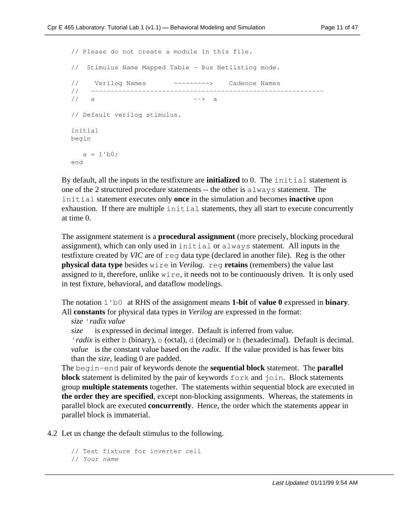
// Please do not create a module in this file.
// Stimulus Name Mapped Table - Bus Netlisting mode.
// Verilog Names ---------> Cadence Names// -----------------------------------------------------------// a --> a
// Default verilog stimulus.
initialbegin
a = 1'b0;end
By default, all the inputs in the testfixture are initialized to 0. The initial statement isone of the 2 structured procedure statements -- the other is always statement. Theinitial statement executes only once in the simulation and becomes inactive uponexhaustion. If there are multiple initial statements, they all start to execute concurrentlyat time 0.
The assignment statement is a procedural assignment (more precisely, blocking proceduralassignment), which can only used in initial or always statement. All inputs in thetestfixture created by VIC are of reg data type (declared in another file). Reg is the otherphysical data type besides wire in Verilog. reg retains (remembers) the value lastassigned to it, therefore, unlike wire , it needs not to be continuously driven. It is only usedin test fixture, behavioral, and dataflow modelings.
The notation 1'b0 at RHS of the assignment means 1-bit of value 0 expressed in binary .All constants for physical data types in Verilog are expressed in the format:
size ' radix valuesize is expressed in decimal integer. Default is inferred from value.' radix is either b (binary), o (octal), d (decimal) or h (hexadecimal). Default is decimal.value is the constant value based on the radix. If the value provided is has fewer bitsthan the size, leading 0 are padded.
The begin-end pair of keywords denote the sequential block statement. The parallelblock statement is delimited by the pair of keywords fork and join . Block statementsgroup multiple statements together. The statements within sequential block are executed inthe order they are specified, except non-blocking assignments. Whereas, the statements inparallel block are executed concurrently. Hence, the order which the statements appear inparallel block is immaterial.
4.2 Let us change the default stimulus to the following.
// Test fixture for inverter cell// Your name

Cpr E 465 Laboratory: Tutorial Lab 1 (v1.1) ¾ Behavioral Modeling and Simulation Page 12 of 47
Last Updated: 01/11/99 9:54 AM
initialbegin a = 1'b0; #80 $finish;end
always #20 a = ~a;
The hash character # specifies the delay. Hence, #80 means delay for 80 time units. Sincethis is within a sequential block, it means delay the execution of next statement ($finish )for 80 time units from the previous statement (a = 1'b0 ).
The $finish system task is the built-in task in Verilog. Upon executing the $finishtask, the simulator will end and discard all other statements, analogous to exit() functionin programming,
The always statement continuously repeats itself throughout the simulation. If there aremultiple always statements, they all start to execute concurrently at time 0. Theprocedural assignment statement in always is delayed for 20 time unit. THIS IS
IMPORTANT . Without the delay, the simulator will be caught in an infinite loop at time 0.So, if your simulation ever runs into what seems like an infinite loop, check if you have sucha zero-delay always statement. The a value is negated every 20 time units until$finish is encountered. Hence, a will toggle 8 times, i.e. 4 cycles.
When done, save and close the editor. The CIW should display the messageAnalyzing testfixture file "testfixture.new"Done
4.3 In VIC window, choose Simulation | Start Interactive to compile our behavior design andtestfixture. The following message will appear in VIC to indicate the completion ofcompilation.
Highest level modules:testType ? for help
C1 >
To run the simulation, choose Simulation | Continue . The following message will appear inVIC window to indicate the end of simulation.
35 simulation eventsCPU time: 0.3 secs to compile + 0.4 secs to link + 0.1 in simulationEnd of VERILOG-XL 2.5.20 Aug 28, 1998 21:02:11
5. Digital Waveform Viewer with SimWave
5.1 To examine the simulation result, we will use the Cadence's digital waveform viewer calledSimWave. To invoke SimWave, choose Debug | Utilities-> | View Waveform... in VIC window.

Cpr E 465 Laboratory: Tutorial Lab 1 (v1.1) ¾ Behavioral Modeling and Simulation Page 13 of 47
Last Updated: 01/11/99 9:54 AM
A SimWave window will appear. Choose Edit | Add Signals... In SimWave Browser form,double click on test in Instances field, and top will appear in the Instances field. Doubleclick top , and a and abar will appear in the Signals sub-window. Highlight both a andabar by clicking on a and then holding down shift and clicking on abar . Click on DisplaySignals button (looks like a clock waveform towards the top of the window). The twosignals should apppear in the window. Click on the Close button to close the SimWaveBrowser.
The waveforms should appear in the Simwave window, however, they aren't centered withinthe window. In the Simwave window, choose View | Zoom Fit . Verify that the output is infact correct.
The Measurement Region is located in the upper right-hand corner of the SimWave window.Look for the field Time in ns . By default, the time unit for simulation is 1 ns. Click LMB inthe middle of the SimWave window, you will notice a vertical Cursor line appears, and theposition is updated to the C1 field in Measurement Region. Delta field tells the distance ofC1 line from the C2 line. To move C2, click MMB and C2 should go to that position. Letus add a grid, so that the time is easier to read on the plot. Go to Options | Grid-> | ShowTime Grid , a grid occurring every 10 ns should appear in the SimWave window.
Add this grid to every plot that you turn in. It will make it easier to read.
When done, go to File | Exit to close SimWave.
5.2 (TI) Let us add some delay to our inverter. Back to the Reading window of behavioralcellview, choose Design | Open... In Open Design form, click on Browse button. TheLibrary Browser window should come to the foreground. Click on the behavioral cellviewof inverter cell. Your selection should be reaffirmed by Cell Name and View Name fields,which should read inverter and behavioral respectively. Leave the Mode selection on edit.Click on OK.
In the editor window that pops up, change the assignment statement to the following.
assign #2 abar = ~a;
This will delay the abar by 2 time units. Save and close the editor.
Back to the VIC window, choose Simulation | Start Interactive again. In the RenetlistDesign? dialog box, click on Yes. Since you have changed your behavioral design, thenetlist will be different. Therefore, we want to renetlist the design. Upon completion ofcompilation, choose Simulation | Continue . Upon completion of simulation, choose Debug |Utilities-> | View Waveform... In the SimWave window, add all the signals. Verify that abaris in fact delayed by 2 time units. Use C1 and C2 to verify the delays thru the Delta field in
Cpr E 465 Laboratory: Tutorial Lab 1 (v1.1) ¾ Behavioral Modeling and Simulation Page 14 of 47
Last Updated: 01/11/99 9:54 AM
Measurement Region. You may want to choose View | Zoom In By 2 to get a bettermeasurement.
There is no way of adding comments to the plot, so you will need to write your name andany other comments on all the plots you turn in.
5.3 To plot the waveform, choose File | Print-> | Single-Page... In the Generate Postscript formclick on OK . Go to the terminal you started cadence from and type lp shm.ps. This shouldprint your file out.
To plot the behavioral cellview, in Reading window for behavioral cellview, choose Design |Print. When done, choose Design | Close Window .
6. More Behavioral Design
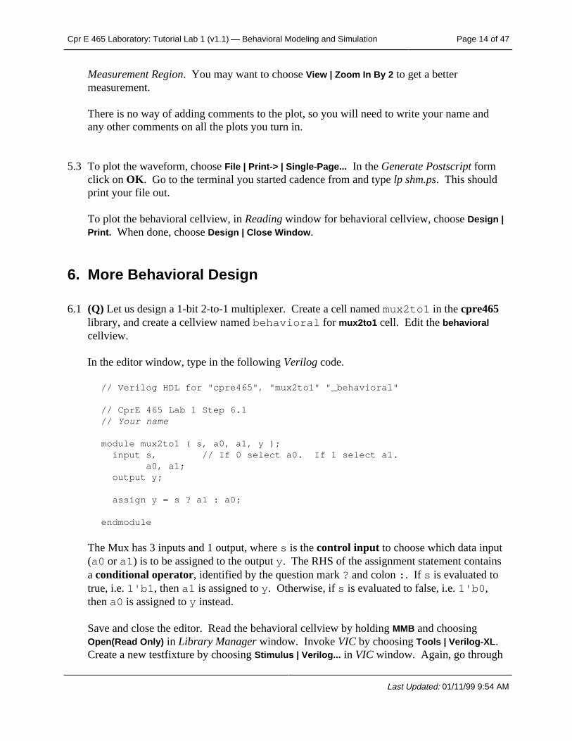
6.1 (Q) Let us design a 1-bit 2-to-1 multiplexer. Create a cell named mux2to1 in the cpre465library, and create a cellview named behavioral for mux2to1 cell. Edit the behavioralcellview.
In the editor window, type in the following Verilog code.
// Verilog HDL for "cpre465", "mux2to1" "_behavioral"
// CprE 465 Lab 1 Step 6.1// Your name
module mux2to1 ( s, a0, a1, y ); input s, // If 0 select a0. If 1 select a1. a0, a1; output y;
assign y = s ? a1 : a0;
endmodule
The Mux has 3 inputs and 1 output, where s is the control input to choose which data input(a0 or a1) is to be assigned to the output y . The RHS of the assignment statement containsa conditional operator, identified by the question mark ? and colon : . If s is evaluated totrue, i.e. 1'b1 , then a1 is assigned to y . Otherwise, if s is evaluated to false, i.e. 1'b0 ,then a0 is assigned to y instead.
Save and close the editor. Read the behavioral cellview by holding MMB and choosingOpen(Read Only) in Library Manager window. Invoke VIC by choosing Tools | Verilog-XL .Create a new testfixture by choosing Stimulus | Verilog... in VIC window. Again, go through

Cpr E 465 Laboratory: Tutorial Lab 1 (v1.1) ¾ Behavioral Modeling and Simulation Page 15 of 47
Last Updated: 01/11/99 9:54 AM
the procedure described in step 4.1 to make and use testfixture.new. I Hope to come up withsome sort of code that will automate this process, but for now, you will have to do itmanually, sorry. Type in the test fixture below for testfixture.new.
// Test fixture for mux2to1 cell// Your name
initialbegin s = 1'b0; {a1, a0} = 2'b01;
#10 s = 1'b1; #10 {a1, a0} = 2'b10; #10 s = 1'b0;
#10 $finish;end
The curly braces are the concatenation operator, i.e. a1 and a0 are grouped together. Alloperands within the concatenation operator must be sized, i.e. their widths must be known.Concatenation operator may be used in either LHS or RHS of assignment statement.
Compile the testfixture by choosing Simulation | Start Interactive in VIC window. Uponcompletion of compilation, choose Simulation | Continue to simulate. Upon completion ofsimulation, choose Debug | Utilities-> | View Waveform... to invoke SimWave. In SimWavewindow, add all the signals. Verify that output y is in fact correct.
6.2 (Q & TI) Similarly, let us add some delay to our Mux. Back to the behavioral cellviewwindow, choose Design | Open... In Open Design form, click on Browse button. In LibraryBrowser window, click on the behavioral cellview of mux2to1 cell. Back to the Open Designform, click on OK.
In the editor window, change the assignment statement.
assign #2 y = s ? a1 : a0;
Save and close the editor. Before we re-simulate our Mux, let us try a slightly different wayof writing the testfixture. In the VIC window, choose Stimulus | Verilog... In the StimulusOptions window set Mode to Copy, testfixture.new should be in the Copy From File Namefield. Type testfixture1.new for the Copy To File Name and click Apply . Change Mode toEdit and make sure testfixture1.new is in the File Name. Click on OK .
Let us change the sequential block to a parallel block.
initialfork s = 1'b0;

Cpr E 465 Laboratory: Tutorial Lab 1 (v1.1) ¾ Behavioral Modeling and Simulation Page 16 of 47
Last Updated: 01/11/99 9:54 AM
{a1, a0} = 2'b01;
#10 s = 1'b1; #20 {a1, a0} = 2'b10; #30 s = 1'b0;
#40 $finish;join
This parallel block is equivalent to the sequential block in the previous step. Since it is aparallel block, we need to change the delay as shown because all statements are executedconcurrently.
Save and close the editor. Re-simulate. When it asks you if you want to renetlist, youshould click YES, because we have changed the cell. Open waveforms. Everything shouldlook the same as before except the output y is delayed by 2 ns. Let us arrange thewaveforms before plotting. You may change the order of the signals by dragging them tothe desired position with MMB(on left hand side of window, where the name of the waves arelocated). We always want to arrange the waveforms in the order of control inputs, datainputs and data outputs, in this case, the order is s , a0 , a1 and y .
Plot the waveforms and close the SimWave window. Print the behavioral cellview. Closethe behavioral cellview.
6.3 (Q & TI) Now, let us create another Mux, but this time, a 1-bit 4-to-1 Mux. Create a cellnamed mux4to1 , and create a cellview named behavioral for mux4to1 cell. Edit thebehavioral cellview.
In the editor window, type in the following Verilog code.
// Verilog HDL for "cpre465", "mux4to1" "_behavioral"
// CprE 465 Lab 1 Step 6.3// Your name
module mux4to1 ( s, a0, a1, a2, a3, y ); input [1:0] s; // 2-bit select input input a0, a1, a2, a3; output y;
assign #2 y = (s == 2'b00) ? a0 : (s == 2'b01) ? a1 : (s == 2'b10) ? a2 : a3;
endmodule
In the Verilog code above, we cascade the conditional operators to allow 4 differentselections. We may also use a different way of nested conditional operators as follow.
Cpr E 465 Laboratory: Tutorial Lab 1 (v1.1) ¾ Behavioral Modeling and Simulation Page 17 of 47
Last Updated: 01/11/99 9:54 AM
assign #2 y = s[1] ? (s[0] ? a3 : a2) : (s[0] ? a1 : a0);
The selection input s is declared as a 2-bit wide input port, with the MSB (most significantbit) as 1 and LSB (least significant bit) as 0. The multi-bit net is called a vector or bus. Thewidth (number of bits) of the vector is specified through the MSB and LSB declared, i.e.Width = MSB - LSB + 1, which must be non-negative integers.
To access the individual bit of the vector, use the square brackets [] , known as the selectoperator, with the index of the bit. The index must be an integer within MSB and LSBdeclared, inclusive.
input [3:0] b;reg [7:0] x;
LHS_expression = b[2];x[5] = RHS_expression ;
All the bits of the vector can be referred together without the square brackets.
LHS_expression = b;x = RHS_expression ;
A continuous range of the vector is called a slice. A slice can be accessed using part-select /range-select.
LHS_expression = b[2:1];x[6:3] = RHS_expression ;
Although Verilog does not restrict the indices and the order of vector, as convention, wealways declare a vector with a 0 for LSB and the largest integer for the MSB.
Use either one of the methods listed previously for the conditional operator. Save and closethe editor. Invoke VIC. Create a testfixture as shown below.
// Test fixture for mux4to1 cell// Your name
initialbegin s = 2'b00; {a3, a2, a1, a0} = 4'b0001;
#10 s = 2'b01; #10 s = 2'b10; #10 s = 2'b11; #10 {a3, a2, a1, a0} = 4'b0010; s = 2'b00; #10 s = 2'b01;

Cpr E 465 Laboratory: Tutorial Lab 1 (v1.1) ¾ Behavioral Modeling and Simulation Page 18 of 47
Last Updated: 01/11/99 9:54 AM
#10 s = 2'b10; #10 s = 2'b11; #10 {a3, a2, a1, a0} = 4'b0100; s = 2'b00; #10 s = 2'b01; #10 s = 2'b10; #10 s = 2'b11; #10 {a3, a2, a1, a0} = 4'b1000; s = 2'b00; #10 s = 2'b01; #10 s = 2'b10; #10 s = 2'b11; #10 {a3, a2, a1, a0} = 4'b0000;
#10 $finish;end
Save and close the editor. Simulate and open the waveforms. Is the output correct?
6.4 (TI) Next, we will explore an alternate behavioral construct to model the same functionality,namely if-then-else statement, similarly to that in programming languages.
The if statement can only be used within structured procedure statements, i.e. initialand always statements. Since we want the output to be continuously valid, alwaysstatement is the choice.
In additional, since only procedural assignments are allowed within always (as well asinitial ) statement, output y has to be declared as reg instead of the default wire .
// CprE 465 Lab 1 Step 6.3// Your name
module mux4to1 ( s, a0, a1, a2, a3, y ); input [1:0] s; // 2-bit select input input a0, a1, a2, a3; output y; reg y;
always #2 if (s == 2'b00) y = a0; else if (s == 2'b01) y = a1; else if (s == 2'b10) y = a2; else y = a3;
endmodule
Cpr E 465 Laboratory: Tutorial Lab 1 (v1.1) ¾ Behavioral Modeling and Simulation Page 19 of 47
Last Updated: 01/11/99 9:54 AM
As we learn in Step 4.2, there must be some delay within an always statement. Otherwise,we will run into an infinite loop.
Re-simulate and open waveforms. Does the output look the same?
6.5 (TI) The output may look OK, but there is a serious flaw in our mux4to1 design. To exhibitsuch a bug, let us change the delay in the always statement to 3 time units.
always #3 if (s == 2'b00) y = a0; else if (s == 2'b01) y = a1; else if (s == 2'b10) y = a2; else y = a3;
Re-simulate and open the waveforms. When it asks you if you want to renetlist, you shouldclick NO, because we haven't changed the cell, we have just changed the testfixture. If youclick on YES, it will give the same results, but it will take a little longer, because it willrenetlist that didn't need renetlisted. Naturally, we would expect the delay between theinputs and output to be 3 ns, but it is NOT. In fact, at some events, the delays are 1 ns. Atother events, the delays are 2 ns and 3 ns. What is wrong?
6.6 (Q & TI) In the always statement of our mux4to1, we actually asked Verilog to re-evaluate the output every 3 ns, instead of evaluating the output 3 ns after the inputs. Toaccount for such behavior, we need to modify the way the always statement is triggered.
always @( s ) #3 if (s == 2'b00) y = a0; else if (s == 2'b01) y = a1; else if (s == 2'b10) y = a2; else y = a3;
The at character, @, is the event capturer/recognizer, i.e. whenever s value changes (eithers[1] or s[0] ), the always statement will be triggered and executed. Otherwise, nothingis executed.
This sounds like it should fix the problem. In fact, a re-simulation will give the rightwaveforms this time. This is deceiving, because it is still not correct. If you are notconvinced, try the following testfixture.
initial
Cpr E 465 Laboratory: Tutorial Lab 1 (v1.1) ¾ Behavioral Modeling and Simulation Page 20 of 47
Last Updated: 01/11/99 9:54 AM
begin s = 2'b00; {a3, a2, a1, a0} = 4'b0001;
#4 a0 = 1'b0; #4 a0 = 1'b1; #2 s = 2'b01; #4 a1 = 1'b1; #4 a1 = 1'b0; #2 s = 2'b10; #4 a2 = 1'b1; #4 a2 = 1'b0; #2 s = 2'b11; #4 a3 = 1'b1; #4 a3 = 1'b0;
#2 s = 2'b00; {a3, a2, a1, a0} = 4'b0010; #4 a0 = 1'b1; #4 a0 = 1'b0; #2 s = 2'b01; #4 a1 = 1'b0; #4 a1 = 1'b1; #2 s = 2'b10; #4 a2 = 1'b1; #4 a2 = 1'b0; #2 s = 2'b11; #4 a3 = 1'b1; #4 a3 = 1'b0;
#12 $finish;end
What the above testfixture does is changes a0 value when s is 2'b00 , change a1 valuewhen s is 2'b01 , and so on. Since this is a Mux the output should follow the input that isselected. Does the waveform appear to be correct?
6.7 (TI) To fix it, we need to include all the inputs in the event recognizing list.
always @( s or a0 or a1 or a2 or a3 ) #3 if (s == 2'b00) y = a0; else if (s == 2'b01) y = a1; else if (s == 2'b10) y = a2; else y = a3;
Re-simulate and open waveforms. Is the output correct now?
In fact, there is another way of writing the nested if-then-else statement. Similar toprogramming languages, Verilog also supports the multiway branching construct throughthe case statement. Hence, the if-then-else statement above can be rewritten.
always @( s or a0 or a1 or a2 or a3 ) #3 case ( s ) 2'b00: y = a0; 2'b01: y = a1; 2'b10: y = a2; 2'b11: y = a3; default: $display("Unknown select = %b", s); endcase
Cpr E 465 Laboratory: Tutorial Lab 1 (v1.1) ¾ Behavioral Modeling and Simulation Page 21 of 47
Last Updated: 01/11/99 9:54 AM
Don't you agree that the code using the case statement is more readable and concise? Thedefault statement is executed if none of the alternatives match. You may wonder whatother possible values can s be. Well, there are 2'b0x , 2'bx1 , etc.
The $display is a system task that displays the string in its argument, the syntax is verysimilar to printf() in C. The format specifier, %b, is used to print the argument inbinary format and the width s was declared, in this case, 2 bits.
6.8 (TI) We may also use the quasi-continuous (procedural continuous) assignment as follow,instead of including the inputs in the event recognizing list above.
always @( s ) #3 case ( s ) 2'b00: assign y = a0; 2'b01: assign y = a1; 2'b10: assign y = a2; 2'b11: assign y = a3; default: $display("Unknown select = %b", s); endcase
Modify your behavioral cellview and re-simulate. Does the output look ok?
When a quasi-continuous (procedural continuous) assignment is executed, it becomesactive — it continuously assigns the RHS to the LHS until it is deactivated usingdeassign statement, or another quasi-continuous assignment of same LHS is executed,which overrides the previous assignment. However, the delay associated with quasi-continuous assignment is only applied during the activation of the assignment, but it doesnot delay the changes of input to be assigned to the output. Hence, quasi-continuous doesnot deliver what we want. Nevertheless, if delay is ignored, then quasi-continuousassignment will work equivalently as the inputs in the event recognizing list.
However, if you use the testfixture in Step 6.3 instead (I Hope you followed my advice andmade seperate testfixtures or this will unnecessary busy work). The output will be the sameas that of Step 6.7. Why?
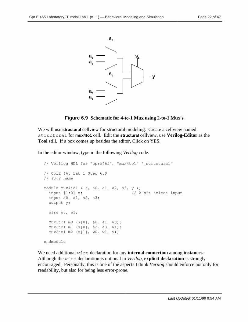
6.9 (TI) You may wonder why not take advantage of the 2-to-1 Mux we have designed earlier tobuild a 4-to-1 Mux. Sure, we can. A 4-to-1 Mux can be built using 3 2-to-1 Mux's as shownin Figure 6.9 below. Let us learn how to design circuit hierarchically using structuralmodeling.
Cpr E 465 Laboratory: Tutorial Lab 1 (v1.1) ¾ Behavioral Modeling and Simulation Page 22 of 47
Last Updated: 01/11/99 9:54 AM
Figure 6.9 Schematic for 4-to-1 Mux using 2-to-1 Mux's
We will use structural cellview for structural modeling. Create a cellview namedstructural for mux4to1 cell. Edit the structural cellview, use Verilog-Editor as theTool still. If a box comes up besides the editor, Click on YES.
In the editor window, type in the following Verilog code.
// Verilog HDL for "cpre465", "mux4to1" "_structural"
// CprE 465 Lab 1 Step 6.9// Your name
module mux4to1 ( s, a0, a1, a2, a3, y ); input [1:0] s; // 2-bit select input input a0, a1, a2, a3; output y;
wire w0, w1;
mux2to1 m0 (s[0], a0, a1, w0); mux2to1 m1 (s[0], a2, a3, w1); mux2to1 m2 (s[1], w0, w1, y);
endmodule
We need additional wire declaration for any internal connection among instances.Although the wire declaration is optional in Verilog, explicit declaration is stronglyencouraged. Personally, this is one of the aspects I think Verilog should enforce not only forreadability, but also for being less error-prone.
a0
a1
a2
a3
y
s0
s0
s1
Cpr E 465 Laboratory: Tutorial Lab 1 (v1.1) ¾ Behavioral Modeling and Simulation Page 23 of 47
Last Updated: 01/11/99 9:54 AM
The instantiation statement is first specified with the master module, in this casemux2to1 . Following that is the instance name, which must be unique within the uppermodule instantiated. There are 3 instances of mux2to1, namely m0, m1 and m2.
The parameters within the parentheses are the port list . This method of port connection isknown as connection by order (or positional association), where the ports of the module towhich the signals/nets of the instance connect are based on the order the ports declared in themodule instantiated. For example, s[0] connects to input s of instance m0, w0 connects tooutput y of instance m0, a2 connects to input a0 of instance m1, w0 connects to input a0 ofinstance m2, etc.
Save and close the editor. Open the structural cellview in read mode and invoke VIC. In the"VLOGIF DESIGN-SWITCH" dialog box that pops up, click on Yes.
Edit the testfixture since we already created it before. Use the testfixture shown in Step 6.3.Simulate and open waveforms. Is the output correct? Why are there glitches (statichazards)? Explain.
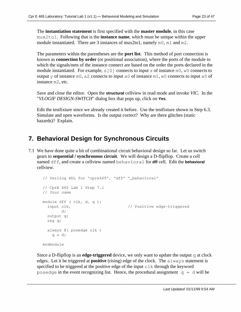
7. Behavioral Design for Synchronous Circuits
7.1 We have done quite a bit of combinational circuit behavioral design so far. Let us switchgears to sequential / synchronous circuit. We will design a D-flipflop. Create a cellnamed dff , and create a cellview named behavioral for dff cell. Edit the behavioralcellview.
// Verilog HDL for "cpre465", "dff" "_behavioral"
// CprE 465 Lab 1 Step 7.1// Your name
module dff ( clk, d, q ); input clk, // Positive edge-triggered d; output q; reg q;
always @( posedge clk ) q = d;
endmodule
Since a D-flipflop is an edge-triggered device, we only want to update the output q at clockedges. Let it be triggered at positive (rising) edge of the clock. The always statement isspecified to be triggered at the positive edge of the input clk through the keywordposedge in the event recognizing list. Hence, the procedural assignment q = d will be

Cpr E 465 Laboratory: Tutorial Lab 1 (v1.1) ¾ Behavioral Modeling and Simulation Page 24 of 47
Last Updated: 01/11/99 9:54 AM
executed only at every rising edge of input clk . Alternatively, to recognize a negative(falling) edge, use the keyword negedge .
Save and close the behavioral cellview. Invoke VIC and simulate using the testfixture asshown below.
// Test fixture for dff cell// Your name
initialbegin clk = 1'b0; d = 1'b0;
#25 d = 1'b1; #10 d = 1'b0; #40 d = 1'b1; #30 d = 1'b0; #10 d = 1'b1;
#30 $finish;end
always #10 clk = ~clk; // Free-running clock at 50 MHz
Is the output correct?
7.2 You should have noticed that the 1st 10 ns of output q is x (undefined/unknown). This isbecause the default initialized value for reg is undefined x , until a new value is assignedto it. In real life, a register / flipflop circuit will start with a definite value, but undetermined(can be 0 or 1) during power up, instead of x . Hence, we can modify our D-flipflop, so thatthe output q starts with a definite value, let’s say 0.
Modify the behavioral cellview of your dff and re-simulate.
module dff ( clk, d, q ); input clk, // Positive edge-triggered d; output q; reg q;
initial q = 1'b0; // Initialized to 0
always @( posedge clk ) q = d;
endmodule
Cpr E 465 Laboratory: Tutorial Lab 1 (v1.1) ¾ Behavioral Modeling and Simulation Page 25 of 47
Last Updated: 01/11/99 9:54 AM
As you learned in Step 4.1, the initial statement will only be executed once at thebeginning of simulation (since no delay is imposed). Hence, the output q will start withvalue 0 instead of undefined x .
How is the output now?
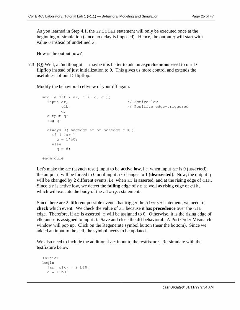
7.3 (Q) Well, a 2nd thought — maybe it is better to add an asynchronous reset to our D-flipflop instead of just initialization to 0. This gives us more control and extends theusefulness of our D-flipflop.
Modify the behavioral cellview of your dff again.
module dff ( ar, clk, d, q ); input ar, // Active-low clk, // Positive edge-triggered d; output q; reg q;
always @( negedge ar or posedge clk ) if ( !ar ) q = 1'b0; else q = d;
endmodule
Let's make the ar (asynch reset) input to be active low, i.e. when input ar is 0 (asserted),the output q will be forced to 0 until input ar changes to 1 (deasserted). Now, the output qwill be changed by 2 different events, i.e. when ar is asserted, and at the rising edge of clk .Since ar is active low, we detect the falling edge of ar as well as rising edge of clk ,which will execute the body of the always statement.
Since there are 2 different possible events that trigger the always statement, we need tocheck which event. We check the value of ar because it has precedence over the clkedge. Therefore, if ar is asserted, q will be assigned to 0. Otherwise, it is the rising edge ofclk, and q is assigned to input d. Save and close the dff behavioral. A Port Order Mismatchwindow will pop up. Click on the Regenerate symbol button (near the bottom). Since weadded an input to the cell, the symbol needs to be updated.
We also need to include the additional ar input to the testfixture. Re-simulate with thetestfixture below.
initialbegin {ar, clk} = 2'b10; d = 1'b0;

Cpr E 465 Laboratory: Tutorial Lab 1 (v1.1) ¾ Behavioral Modeling and Simulation Page 26 of 47
Last Updated: 01/11/99 9:54 AM
#5 ar = 1'b0; #5 ar = 1'b1;
#15 d = 1'b1; #10 d = 1'b0; #40 d = 1'b1; #30 d = 1'b0; #10 d = 1'b1;
#30 ar = 1'b0; #10 ar = 1'b1;
#20 ar = 1'b0; #10 ar = 1'b1;
#30 $finish;end
always #10 clk = ~clk; // Free-running clock at 50 MHz
Is the output correct?
7.4 In the cases which output q depends on multiple events, the event recognizing list of thealways statement can become quite long, and the body of the always statement needs tocheck all possible combinations of events. We can split both events into 2 differentalways statements. Modify the behavioral cellview of your dff again.
module dff ( ar, clk, d, q ); input ar, // Active-low clk, // Positive edge-triggered d; output q; reg q;
always @( ar ) if ( !ar ) assign q = 1'b0; // Quasi-continuous assignment else deassign q; // Disable quasi-continuous
always @( posedge clk ) q = d; // Procedural assignment
endmodule
Whenever ar is asserted, output q must be forced to 0, regardless of the value of d at therising edge of clk . And ar should remain 0 until ar is deasserted. Therefore, we need touse a quasi-continuous assignment, which will override the procedural assignment to thesame register, in this case q. Hence, when ar is asserted, even though the 2nd always

Cpr E 465 Laboratory: Tutorial Lab 1 (v1.1) ¾ Behavioral Modeling and Simulation Page 27 of 47
Last Updated: 01/11/99 9:54 AM
statement is also triggered at rising edge of clk , the procedural assignment has no effect onq because the quasi-continuous assignment on q is active.
However, most of time, we tend to forget to disable the quasi-continuous assignment when itis no longer needed, which results in the output q to be 0 even when ar has been deasserted.Hence, we need to disable/deactivate the quasi-continuous assignment to q if ar is 1(deasserted), so that the output q will follow input d at the next rising edge of clk .
Re-simulate. Is output the same as that in Step 7.3?
7.5 Now, we want to add an additional output qbar , which is the complement of output q.
Modify the behavioral cellview of your dff again.
module dff ( ar, clk, d, q, qbar ); input ar, // Active-low
clk, // Positive edge-triggeredd;
output q, qbar; reg q, qbar;
always @( ar ) if ( !ar ) assign {q, qbar} = 2'b01; // Quasi-continuous assignment else deassign {q, qbar}; // Disable quasi-continuous
always @( posedge clk ) begin q = d; // Procedural assignment qbar = ~d; end
endmodule
In the always statement that recognizes ar , we use the concatenation operator tocombine both q and qbar for quasi-continuous assignment as well as deassignment.Alternatively, we can use separate assign and deassign statements for qbar . However, ifwe use more than one statement within the if and else clauses, we need to enclose themwithin a block (either sequential or parallel). Such usage is shown in the always statementthat recognizes positive edge of clk . Since assignments to q and qbar are concurrently,we may also use fork-join (parallel block) instead of begin-end (sequential block).
Since we only added an output port, we don’t need to modify our testfixture. Re-simulate.Are the outputs correct?
7.6 In fact, since the output qbar is always the negation of output q, we can describe it in amore concise way.

Cpr E 465 Laboratory: Tutorial Lab 1 (v1.1) ¾ Behavioral Modeling and Simulation Page 28 of 47
Last Updated: 01/11/99 9:54 AM
Modify the behavioral cellview of your dff as again.
module dff ( ar, clk, d, q, qbar ); input ar, // Active-low clk, // Positive edge-triggered d; output q, qbar; reg q;
always @( ar ) if ( !ar ) assign q = 1'b0; // Quasi-continuous assignment else deassign q; // Disable quasi-continuous
always @( posedge clk ) q = d; // Procedural assignment
assign qbar = ~q; // Continuous assignment
endmodule
Instead of specifying qbar in every place q is specified, we can use a continuousassignment to drive qbar as the negation of q. However, a continuous assignmentrequires the LHS, i.e. qbar , to be a wire net instead of a reg .
Is output qbar the same as that in Step 7.5?
7.7 (TI) Next, we will add some delay to our D-flipflop. Instead of specifying delay as constant,let us explore the use of the parameter type.
Modify the behavioral cellview of your dff again.
module dff ( ar, clk, d, q, qbar ); input ar, // Active-low clk, // Positive edge-triggered d; output q, qbar; reg q;
parameter dly = 2; // Constant for delay
always @( ar ) #dly if ( !ar ) assign q = 1'b0; // Quasi-continuous assignment else deassign q; // Disable quasi-continuous
always @( posedge clk ) q = #dly d; // Procedural assignment,

Cpr E 465 Laboratory: Tutorial Lab 1 (v1.1) ¾ Behavioral Modeling and Simulation Page 29 of 47
Last Updated: 01/11/99 9:54 AM
// intra-assignment delay
assign #dly qbar = ~q; // Continuous assignment
endmodule
The delay associated with the procedural assignment of q in the always statementtriggered by positive edge of clk is called an intra-assignment delay, i.e. the RHS isevaluated immediately when executed, but there is a wait after the delay before assignmentto the RHS. Therefore, the intra-assignment delay is equivalent to the following.
reg tmp;
always @( posedge clk ) begin tmp = d; #dly q = tmp; end
Use of parameter for a constant is strongly encouraged. One advantage of usingparameter is — if we decide to use a different value for delay, we can just modify it onceinstead of everywhere it is used. Another main advantage is — values of the parameter canbe overridden separately for different instances of the same modules through defparamstatement, or through module-instance-parameter-value-assignment. This allows separatecustomization of instances based on a single module declaration. Rather than discussinghere, I will leave it to you to further explore this powerful feature.
We have examined the output through waveforms. We can also ask Verilog-XL to log thechanges of signals as an ASCII text file. We will use $monitor system task to help uscapture the changes. Edit your testfixture and add the following:
initial $monitor($time, ", ar = %b, clk = %b, d = %b, q = %b, qbar = %b", ar, clk, d, q, qbar);initialbegin.........end
NOTE: Do not break the initial statement into two lines withenter, if it spills over into the next line, that is ok.
The signals to be monitored are listed as arguments of the $monitor system task. Thesystem tasks $time , $stime and $realtime will not trigger $monitor . Hence,whenever any of these signals changes value, $monitor will be executed and print thecurrent time. The binary format specifier is %b, which tells $monitor to display thesignals in binary format. Other format specifiers are %o (octal), %d (decimal), %h(hexadecimal), %v (strength), %t (time), %s (string), %c (character), %f (floating), %e
Cpr E 465 Laboratory: Tutorial Lab 1 (v1.1) ¾ Behavioral Modeling and Simulation Page 30 of 47
Last Updated: 01/11/99 9:54 AM
(scientific), %g (floating or scientific, whichever is shorter). There is a specifier that needsno argument, %m, which displays the hierarchical name that contains the specifier.
An optional width specifier may be used in conjunction with the format specifier, e.g. %8ddisplays the signal in decimal format and pad leading spaces if the value is fewer than 8digits in decimal ; %0H displays signal in hexadecimal and uses uppercase for hex digits,and does not pad any leading space ; %.3f displays a real variable with 3 digits after thedecimal point, etc.
After the $monitor system task is activated, it can then be deactivated and re-activatedusing $monitoroff and $monitoron system tasks respectively during the simulation.
Save and close your testfixture. Re-simulate.
To view the simulation log, choose File | View Log File from VIC window. To print thesimulation log, 1st choose File | Save As type your favorite file name in the File Namefield. Open the file and edit it so that only the important data is present (the simulationresults), you may also want to add your name, etc. Save and print it. I also plan on makingthis step so that it will be more automated in the future, but don't have enough time, rightnow.
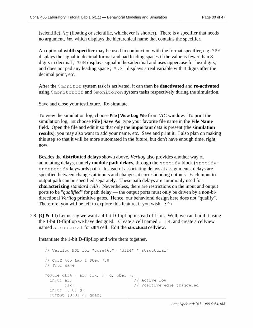
Besides the distributed delays shown above, Verilog also provides another way ofannotating delays, namely module path delays, through the specify block (specify-endspecify keywords pair). Instead of associating delays at assignments, delays arespecified between changes at inputs and changes at corresponding outputs. Each input tooutput path can be specified separately. These path delays are commonly used forcharacterizing standard cells. Nevertheless, there are restrictions on the input and outputports to be "qualified" for path delay — the output ports must only be driven by a non-bi-directional Verilog primitive gates. Hence, our behavioral design here does not "qualify".Therefore, you will be left to explore this feature, if you wish. :^)
7.8 (Q & TI) Let us say we want a 4-bit D-flipflop instead of 1-bit. Well, we can build it usingthe 1-bit D-flipflop we have designed. Create a cell named dff4 , and create a cellviewnamed structural for dff4 cell. Edit the structural cellview.
Instantiate the 1-bit D-flipflop and wire them together.
// Verilog HDL for "cpre465", "dff4" "_structural"
// CprE 465 Lab 1 Step 7.8// Your name
module dff4 ( ar, clk, d, q, qbar ); input ar, // Active-low clk; // Positive edge-triggered input [3:0] d; output [3:0] q, qbar;
Cpr E 465 Laboratory: Tutorial Lab 1 (v1.1) ¾ Behavioral Modeling and Simulation Page 31 of 47
Last Updated: 01/11/99 9:54 AM
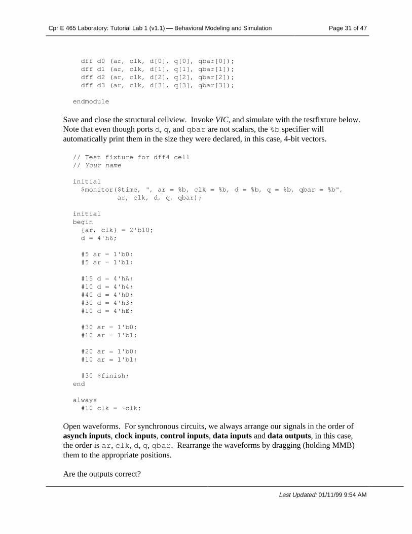
dff d0 (ar, clk, d[0], q[0], qbar[0]); dff d1 (ar, clk, d[1], q[1], qbar[1]); dff d2 (ar, clk, d[2], q[2], qbar[2]); dff d3 (ar, clk, d[3], q[3], qbar[3]);
endmodule
Save and close the structural cellview. Invoke VIC, and simulate with the testfixture below.Note that even though ports d, q, and qbar are not scalars, the %b specifier willautomatically print them in the size they were declared, in this case, 4-bit vectors.
// Test fixture for dff4 cell// Your name
initial $monitor($time, ", ar = %b, clk = %b, d = %b, q = %b, qbar = %b", ar, clk, d, q, qbar);
initialbegin {ar, clk} = 2'b10; d = 4'h6;
#5 ar = 1'b0; #5 ar = 1'b1;
#15 d = 4'hA; #10 d = 4'h4; #40 d = 4'hD; #30 d = 4'h3; #10 d = 4'hE;
#30 ar = 1'b0; #10 ar = 1'b1;
#20 ar = 1'b0; #10 ar = 1'b1;
#30 $finish;end
always #10 clk = ~clk;
Open waveforms. For synchronous circuits, we always arrange our signals in the order ofasynch inputs, clock inputs, control inputs, data inputs and data outputs, in this case,the order is ar , clk , d, q, qbar . Rearrange the waveforms by dragging (holding MMB)them to the appropriate positions.
Are the outputs correct?
Cpr E 465 Laboratory: Tutorial Lab 1 (v1.1) ¾ Behavioral Modeling and Simulation Page 32 of 47
Last Updated: 01/11/99 9:54 AM
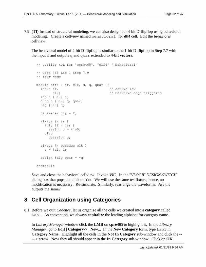
7.9 (TI) Instead of structural modeling, we can also design our 4-bit D-flipflop using behavioralmodeling. Create a cellview named behavioral for dff4 cell. Edit the behavioralcellview.
The behavioral model of 4-bit D-flipflop is similar to the 1-bit D-flipflop in Step 7.7 withthe input d and outputs q and qbar extended to 4-bit vectors.
// Verilog HDL for "cpre465", "dff4" "_behavioral"
// CprE 465 Lab 1 Step 7.9// Your name
module dff4 ( ar, clk, d, q, qbar ); input ar, // Active-low clk; // Positive edge-triggered input [3:0] d; output [3:0] q, qbar; reg [3:0] q;
parameter dly = 2;
always @( ar ) #dly if ( !ar ) assign q = 4'b0; else deassign q;
always @( posedge clk ) q = #dly d;
assign #dly qbar = ~q;
endmodule
Save and close the behavioral cellview. Invoke VIC. In the "VLOGIF DESIGN-SWITCH"dialog box that pops up, click on Yes. We will use the same testfixture, hence, nomodification is necessary. Re-simulate. Similarly, rearrange the waveforms. Are theoutputs the same?
8. Cell Organization using Categories
8.1 Before we quit Cadence, let us organize all the cells we created into a category calledLab1 . As convention, we always capitalize the leading alphabet for category name.
In Library Manager window click the LMB on cpre465 to highlight it. In the LibraryManager, go to Edit | Category-> | New... In the New Category form, type Lab1 inCategory Name. Highlight all the cells in the Not In Category sub-window and click the -----> arrow. Now they all should appear in the In Category sub-window. Click on OK .

Cpr E 465 Laboratory: Tutorial Lab 1 (v1.1) ¾ Behavioral Modeling and Simulation Page 33 of 47
Last Updated: 01/11/99 9:54 AM
Now in the Library Manager window, there should be a Lab1 category under cpre465library.
What if we didn't get all the cells we wanted in the category? Double click on Lab1 in theLibrary Manager. Now we could add more cells into the category if we had to.
8.2 When done, quit Cadence before logging out from HP-UX by choosing File | Exit... in CIW.Click on YES.
9. Summary of Verilog Syntax
9.1 Module & Instantiation of Instances
A Module in Verilog is declared within the pair of keywords module and endmodule .Following the keyword module are the module name and port interface list.
module my_module ( a, b, c, d ); input a, b; output c, d; ...endmodule
All instances must be named except the instances of primitives. Only primitives in Verilogcan have anonymous instances, i.e. and , or , nand , nor , xor , xnor , buf , not ,bufif1 , bufi0 , notif1 , notif0 , nmos, pmos, cmos, tran , tranif1 , tranif0 ,rnmos , rpmos , rcmos , rtran , rtranif1 , rtranif0 .
Port Connections at InstantiationsIn Verilog, there are 2 ways of specifying connections among ports of instances.
a) By ordered list (positional association)This is the more intuitive method, where the signals to be connected must appear in themodule instantiation in the same order as the ports listed in module definition.
b) By name (named association)When there are too many ports in the large module, it becomes difficult to track the order.Connecting the signals to the ports by the port names increases readability and reducespossible errors.module top; reg A, B; wire C, D;
my_module m1 (A, B, C, D); // By order my_module m2 (.b(B), .d(D), .c(C), .a(A)); // By name

Cpr E 465 Laboratory: Tutorial Lab 1 (v1.1) ¾ Behavioral Modeling and Simulation Page 34 of 47
Last Updated: 01/11/99 9:54 AM
...
endmodule
Parameterized InstantiationsThe values of parameters can be overridden during instantiation, so that each instance canbe customized separately. Alternatively, defparam statement can be used for the samepurpose.
module my_module ( a, b, c, d ); parameter x = 0;
input a, b; output c, d;
parameter y = 0, z = 0; ...endmodule
module top; reg A, B; wire C, D;
my_module #(2, 4, 3) m1 (A, B, C, D);// x = 2, y = 4, z = 3 in instance m1
my_module #(5, 3, 1) m2 (.b(B), .d(D), .c(C), .a(A));// x = 5, y = 3, z = 1 in instance m2
defparam m3.x = 4, m3.y = 2, m3.z = 5; my_module m3 (A, B, C, D); // x = 4, y = 2, z = 5 in instance m3 ...endmodule
9.2 Data Types
There are 2 groups of data types in Verilog, namely physical and abstract.
a) Physical data type• Net (wire , wand, wor , tri , triand , trior ). Default value is z . Used mainly in
structural modeling.• Register (reg ). Default value is x . Used in dataflow/RTL and behavioral modelings.• Charge storage node (trireg ). Default value is x . Used in gate-level and switch-level modelings.
b) Abstract data type — used only in behavioral modeling and test fixture.• Integer (integer ) stores 32-bit signed quantity.• Time (time ) stores 64-bit unsigned quantity from system task $time .• Real (real ) stores floating-point quantity.• Parameter (parameter ) substitutes constant.

Cpr E 465 Laboratory: Tutorial Lab 1 (v1.1) ¾ Behavioral Modeling and Simulation Page 35 of 47
Last Updated: 01/11/99 9:54 AM
• Event (event ) is only name reference — does not hold value.
Unfortunately, the current standard of Verilog does not support user-defined types, unlikeVHDL. :^(
9.3 Values & Literals
Verilog provides 4 basic values,a) 0 — logic zero or false conditionb) 1 — logic one, or true conditionc) x — unknown/undefined logic value. Only for physical data types.d) z — high-impedance/floating state. Only for physical data types.
Constants in Verilog are expressed in the following format:width ' radix valuewidth — Expressed in decimal integer. Optional, default is inferred from value.' radix — Binary(b), octal(o), decimal(d), or hexadecimal(h). Optional, default is decimal.value — Any combination of the 4 basic values can be digits for radix octal, decimal or
hexadecimal.
4'b1011 // 4-bit binary of value 1011234 // 3-digit decimal of value 2342'h5a // 2-digit (8-bit) hexadecimal of value 5A3'o671 // 3-digit (9-bit) octal of value 6714b'1x0z // 4-bit binary. 2nd MSB is unknown. LSB is Hi-Z.3.14 // Floating point1.28e5 // Scientific notation
There are 8 different strength levels that can be associated by values 0 and 1.Strength
LevelAbbreviation Type Degree
supply0supply1
Su0Su1
driving strongest
strong0strong1
St0St1
driving
pull0pull1
Pu0Pu1
driving
large0large1
La0La1
charge storage
weak0weak1
We0We1
driving
medium0medium1
Me0Me1
charge storage
small0small1
Sm0Sm1
charge storage
highz0highz1
HiZ0HiZ1
weakest

Cpr E 465 Laboratory: Tutorial Lab 1 (v1.1) ¾ Behavioral Modeling and Simulation Page 36 of 47
Last Updated: 01/11/99 9:54 AM
In the case of contention, the stronger signal dominates. Combination of 2 oppositevalues of same strength results in a value of x .
St0 , Pu1 Þ St0Su1, La1 Þ Su1Pu0, Pu1 Þ PuX
9.4 Nets & Registers
Net is the connection between ports of modules within a higher module. Net is used in testfixtures and all modeling abstraction including behavioral. Default value of net is high-Z(z ). Nets just only pass values from one end to the other, i.e. it does not store the value.Once the output device discontinues driving the net, the value in the net becomes high-Z (z ).Besides the usual net (wire ), Verilog also provides special nets (wor , wand) to resolve thefinal logic when there is logic contention by multiple drivers. tri , trior and triand arejust the aliases for wire , wor and wand for readability reason.
Register is the storage that retains (remembers) the value last assigned to it, therefore,unlike wire , it needs not to be continuously driven. It is only used in the test fixture,behavioral, and dataflow modelings. The default value of a register is unknown (x ).
Other special nets in Verilog are the supplies like VCC/VDD (supply1 ), Gnd (supply0 ),pullup (pullup ) and pulldown (pulldown ), resistive pullup (tri1 ) and resistivepulldown (tri0 ), and charge storage/capacitive node (trireg ) which has storagestrength associated with it.
9.5 Vectors & Arrays
Physical data types (wire , reg , trireg ) can be declared as vector/bus (multiple bitwidths). An Array is a chunk of consecutive values of the same type. Data types reg ,integer and time can be declared as an array. Multidimensional arrays are not permittedin Verilog, however, arrays can be declared for vectored register type.
wire [3:0] data; // 4-bit wide vectorreg bit [1:8]; // array of 8 1-bit scalarreg [3:0] mem [1:8]; // array of 8 4-bit vector
The range of vectors and arrays declared can start from any integer, and in either ascendingor descending order. However, when accessing the vector or array, the slice (subrange)specified must be within the range and in the same order as declared.
data[4] // Out-of-rangebit[5:2] // Wrong order
Cpr E 465 Laboratory: Tutorial Lab 1 (v1.1) ¾ Behavioral Modeling and Simulation Page 37 of 47
Last Updated: 01/11/99 9:54 AM
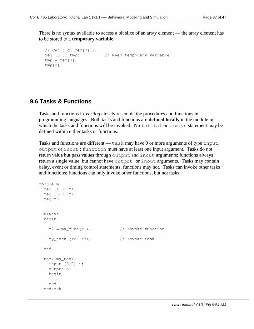
There is no syntax available to access a bit slice of an array element — the array element hasto be stored to a temporary variable.
// Can't do mem[7][2]reg [3:0] tmp; // Need temporary variabletmp = mem[7];tmp[2];
9.6 Tasks & Functions
Tasks and functions in Verilog closely resemble the procedures and functions inprogramming languages. Both tasks and functions are defined locally in the module inwhich the tasks and functions will be invoked. No initial or always statement may bedefined within either tasks or functions.
Tasks and functions are different — task may have 0 or more arguments of type input ,output or inout ; function must have at least one input argument. Tasks do notreturn value but pass values through output and inout arguments; functions alwaysreturn a single value, but cannot have output or inout arguments. Tasks may containdelay, event or timing control statements; functions may not. Tasks can invoke other tasksand functions; functions can only invoke other functions, but not tasks.
module m; reg [1:0] r1; reg [3:0] r2; reg r3;
... always begin ... r2 = my_func(r1); // Invoke function ... my_task (r2, r3); // Invoke task ... end
task my_task; input [3:0] i; output o; begin ... end endtask
Cpr E 465 Laboratory: Tutorial Lab 1 (v1.1) ¾ Behavioral Modeling and Simulation Page 38 of 47
Last Updated: 01/11/99 9:54 AM
...
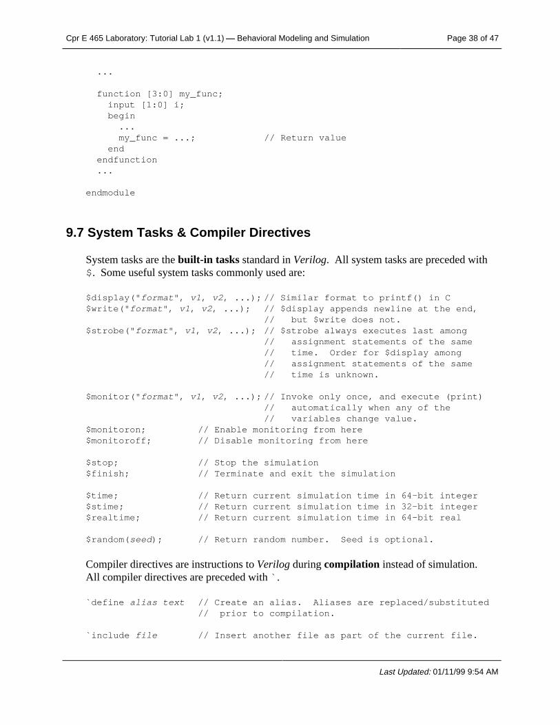
function [3:0] my_func; input [1:0] i; begin ... my_func = ...; // Return value end endfunction ...
endmodule
9.7 System Tasks & Compiler Directives
System tasks are the built-in tasks standard in Verilog. All system tasks are preceded with$. Some useful system tasks commonly used are:
$display(" format ", v1 , v2 , ...); // Similar format to printf() in C$write(" format ", v1 , v2 , ...); // $display appends newline at the end,
// but $write does not.$strobe(" format ", v1 , v2 , ...); // $strobe always executes last among
// assignment statements of the same // time. Order for $display among // assignment statements of the same // time is unknown.
$monitor(" format ", v1 , v2 , ...); // Invoke only once, and execute (print) // automatically when any of the // variables change value.
$monitoron; // Enable monitoring from here$monitoroff; // Disable monitoring from here
$stop; // Stop the simulation$finish; // Terminate and exit the simulation
$time; // Return current simulation time in 64-bit integer$stime; // Return current simulation time in 32-bit integer$realtime; // Return current simulation time in 64-bit real
$random( seed ); // Return random number. Seed is optional.
Compiler directives are instructions to Verilog during compilation instead of simulation.All compiler directives are preceded with ` .
`define alias text // Create an alias. Aliases are replaced/substituted// prior to compilation.
`include file // Insert another file as part of the current file.

Cpr E 465 Laboratory: Tutorial Lab 1 (v1.1) ¾ Behavioral Modeling and Simulation Page 39 of 47
Last Updated: 01/11/99 9:54 AM
`ifdef cond // If cond is defined, compile the following.`else`endif
9.8 Operators
OperatorSymbol
Function Group OperandsPrecedence
Rank
! logical negation Logical unary 1~ bitwise negation Bitwise unary& reduction and Reduction unary| reduction or Reduction unary^ reduction xor Reduction unary
~& reduction nand Reduction unary~| reduction nor Reduction unary~^ reduction xnor reduction unary+ unary positive arithmetic unary- unary negative arithmetic unary
* multiplication arithmetic binary 2/ division arithmetic binary% modulus arithmetic binary
+ addition arithmetic binary 3- subtraction arithmetic binary
<< left shift shift binary 4>> right shift shift binary
< less than relational binary 5<= less than or equal relational binary> greater than relational binary
>= greater than or equal relational binary
== equality equality binary 6!= inequality equality binary
=== case equality equality binary!== case inequality equality binary
& bitwise and bitwise binary 7
^ bitwise xor bitwise binary 8^~ bitwise xnor bitwise binary
| bitwise or bitwise binary 9
&& logical and logical binary 10
|| logical or logical binary 11
Cpr E 465 Laboratory: Tutorial Lab 1 (v1.1) ¾ Behavioral Modeling and Simulation Page 40 of 47
Last Updated: 01/11/99 9:54 AM
?: conditional ternary 12
= blocking assignment assignment binary 13<= non-blocking assignment assignment binary
[] bit-select[ : ] part-select
{} concatenation{ {} } replication
Operators within the same precedence rank are associated from left to right .
Verilog has special syntax restriction on using both reduction and bitwise operators withinthe same expression — even though reduction operator has higher precedence, parenthesesmust be used to avoid confusion with a logical operator.
a & (&b)a | (|b)
Since bit-select, part-select, concatenation and replication operators use pairs of delimitersto specify their operands, there is no notion of operator precedence associated with them.
9.10 Structured Procedures
There are 2 structured procedure statements, namely initial and always . They are thebasic statements for behavioral modeling from which other behavioral statements aredeclared. They cannot be nested, but many of them can be declared within a module.
a) initial statementinitial statement executes exactly once and becomes inactive upon exhaustion. Ifthere are multiple initial statements, they all start to execute concurrently at time 0.
b) always statementalways statement continuously repeats itself throughout the simulation. If there aremultiple always statements, they all start to execute concurrently at time 0. alwaysstatements may be triggered by events using an event recognizing list @( ) .
9.11 Sequential & Parallel Blocks
Block statements group multiple statements together. Block statements can be eithersequential or parallel. Block statements can be nested or named for direct access, anddisabled if named.
a) Sequential block
Cpr E 465 Laboratory: Tutorial Lab 1 (v1.1) ¾ Behavioral Modeling and Simulation Page 41 of 47
Last Updated: 01/11/99 9:54 AM
Sequential blocks are delimited by the pair of keywords begin and end . Thestatements in sequential blocks are executed in the order they are specified, except non-blocking assignments.
b) Parallel blockParallel blocks are delimited by the pair of keywords fork and join . The statements inparallel blocks are executed concurrently. Hence, the order of the statements in parallelblocks are immaterial.
9.12 Assignments
a) Continuous assignmentContinuous assignments are always active — changes in RHS (right hand side)expression is assigned to is LHS (left hand side) net.
LHS must be a scalar or vector of nets, and assignment must be performed outsideprocedure statements.
assign #delay net = expression;
Delay may be associated with the assignment, where new changes in expression isassigned to net after the delay. However, note that such delay is called inertial delay, i.e.if the expression changes again within the delay after the 1st change, only the latestchange is assigned to net after the delay from 2nd change. The 1st change within thedelay is not assigned to net.
b) Procedural assignmentLHS must be a scalar or vector of registers, and assignment must be performed insideprocedure statements (initial or always ). Assignment is only active (evaluated andloaded) when control is transferred to it. After that, the value of register remains until itis reassigned by another procedural assignment.
There are 2 types of procedural assignments:• Blocking assignment
Blocking assignments are executed in the order specified in the sequential block, i.e. ablocking assignment waits for previous blocking assignment of the same time tocomplete before executing.
register = expression;
• Nonblocking assignmentNonblocking assignments are executed concurrently within the sequential blocks, i.e. anonblocking assignment executes without waiting for other nonblocking assignments ofoccurring at the same time to complete.
register <= expression;
Intra-assignment delay may be used for procedural assignment.
Cpr E 465 Laboratory: Tutorial Lab 1 (v1.1) ¾ Behavioral Modeling and Simulation Page 42 of 47
Last Updated: 01/11/99 9:54 AM
register = #delay expression;
The expression is evaluated immediately, but the value is assigned to register after thedelay. This is equivalent to
reg temporary;temporary = expression;#delay register = temporary;
c) Quasi-continuous (procedural continuous) assignmentThe LHS must be a scalar or vector of registers, and assignment must be insideprocedure statements.
Similar to procedural assignment, however quasi-continuous assignment becomes activeand stays active from the point of the assignment until it is deactivated throughdeassignment. When active, quasi-continuous assignment overrides any proceduralassignment to the register.
begin ... assign register = expression1; // Activate quasi-continuous ... register = expression2; // No effect. Overridden by active
// quasi-continuous ... assign register = expression3; // Becomes active and overrides
// previous quasi-continuous ... deassign register; // Disable quasi-continuous ... register = expression4; // Executed. ...end
There is no delay associated with quasi-continuous assignment. . Only the activation maybe delayed. However, once it is activated, any changes in expression will be assigned to theregister immediately.
9.13 Timing Controls
a) Delay-basedExecution of a statement can be delayed by a fixed-time period using the # operator.
#num statement; // Delay num time from previous statement before // executing
Intra-assignment delay
Cpr E 465 Laboratory: Tutorial Lab 1 (v1.1) ¾ Behavioral Modeling and Simulation Page 43 of 47
Last Updated: 01/11/99 9:54 AM
This evaluates the RHS expression immediately, but delays for a fixed-time period beforeassigning to LHS, which must be a register.
register = #num expr; // Evaluate expr now, but delay num time unit // before assigning to register
b) Event-basedExecution of a statement is triggered by the change of value in a register or a net. The @operator captures such change of value within its recognizing list. To allow multipletriggers, use or between each event.
@(signal) statement; // Execute whenever signal changes values@(posedge signal) statement;// Execute at positive edge of signal@(negedge signal) statement;// Execute at negative edge of signalregister = @(signal) expr; // Similar to intra-assignmentalways @(s1 or s2 or s3) // Enter always block when either s1, s2 ... // or s3 changes value
Level-sensitiveThe @ is edge-sensitive. To achieve level-sensitive, use additional if statement to checkthe values of each event.
always @(signal) if ( signal ) ... else ...
Alternatively, combination of always and wait can be used. But, note that wait is ablocking statement, i.e. wait blocks following statement until the condition is true.
always wait (event) statement; // Execute statement when event is true
c) Named-eventEvent is explicitly triggered (with -> operator) and recognized (with @ operator). Notethat the named event cannot hold any data.
event my_event; // Declare an event
always @( my_event ) // Execute when my_event is triggeredbegin ...end
alwaysbegin ... if (...)
Cpr E 465 Laboratory: Tutorial Lab 1 (v1.1) ¾ Behavioral Modeling and Simulation Page 44 of 47
Last Updated: 01/11/99 9:54 AM
-> my_event; // Trigger my_event ...end
9.14 Conditional Statements
The body only allows a single statement. If multiple statements are desired, blockstatements may be used to enclose multiple statements in place of the body.
a) If-Then-Elseif ( expr ) statement;
if ( expr ) statement;else statement;
if ( expr ) statement;else if ( expr ) statement;else if ( expr ) statement;else statement;
b) Casecase ( expr ) value1 : statement; value2 : statement; value3 : statement; ... default : statement;endcase
9.15 Loop Statements
The body only allows a single statement. If multiple statements are desired, blockstatements may be used to enclose multiple statements in place of the body.
a) Whilewhile ( expr ) statement;
b) Forfor ( init ; expr ; step ) statement;
c) RepeatIterations are based on a constant instead of conditional expression.
repeat ( constant ) // Fix number of loops statement;
Cpr E 465 Laboratory: Tutorial Lab 1 (v1.1) ¾ Behavioral Modeling and Simulation Page 45 of 47
Last Updated: 01/11/99 9:54 AM
d) Foreverforever // Same as while (1) statement;
References:
[1] "Verilog-XL Reference Manual ver 2.2." OpenBook, Cadence Design Systems, 1995.
[2] Samir Palnitkar. "Verilog HDL: A Guide to Digital Design and Synthesis." SunSoft Press,1996.
[3] Donald Thomas, Phil Moorby. "The Verilog Hardware Description Language, 2nd ed."Kluwer Academic Publishers, 1994.
[4] Eli Sternheim, Rajvir Singh, Rajeev Madhavan, Yatin Trivedi. "Digital Design andSynthesis with Verilog HDL." Automata Publishing Company, 1993.
Problem:
(TI) Design a 4-bit synchronous up/down counter with preset (load) and asynchronous resetusinga) behavioral modelingb) structural modeling with bit-slicing, i.e. instantiate 1-bit counters.Use delay of 1 time unit in all assignments.
Begin with the following module declarationmodule counter4 ( ar, clk, load, up, d, q );
Hint for (b): You may need to add extra ports to your 1-bit “synchronous” counter.
Your grade depends ona) efficiency of your designs, e.g. concise modeling using Verilog,b) readability of your designs, e.g. proper indentations, comments,c) effectiveness of your test benches, e.g. exhibition of worst-case.
Note: If you choose to copy a design from a book, make sure you cite the reference.Otherwise, you are plagiarizing. Your TA may ask you to explain the design todemonstrate your understanding.
Questions:
1. Comment on the effectiveness of the test benches used in Steps 6.1, 6.2, 6.3, 6.6, 7.3 and7.8. e.g., do they exhibit the worst case? How? Justify your comments, i.e. explain why youthink so.

Cpr E 465 Laboratory: Tutorial Lab 1 (v1.1) ¾ Behavioral Modeling and Simulation Page 46 of 47
Last Updated: 01/11/99 9:54 AM
2. What is the one thing all designs in a given library share in Cadence's DFII?
3. Given a design, is there a definite way to define the hierarchy? If yes, how? If no, why? Ifnecessary, support your argument with example.
4. Why are all complex digital circuits synchronous?
5. Go to the library or the web and search for articles or books, find out why and how someoneclaims Verilog is better than VHDL and vice versa. Collect at least 3 justifications for bothsides of arguments. Limit each justification to maximum 2 sentences with optional example.Cite your references.
6. Explain the differences between the 2 equality operators, == and ===. (Likewise, forinequality operators, != and !== ). Illustrate using simple examples in Verilog.
7. What are logical, bitwise, and reduction operators? Show a simple example for each type.
8. How does the $strobe system task differ from the $display system task? Explain.When are they typically used?
9. We know the outputs of and gate and or gate given any combination of 0 and 1. Find outthe outputs of an and gate and an or gate if one or both the inputs are either x or z . Showyour answers in tabular form.
10. Let's say we replace the testfixture of Step 6.3 with the following testfixture. What is wrongwith the following testfixture? How can you fix it without changing the intended test?
reg [3:0] a;
initialbegin assign {a3, a2, a1, a0} = a;
for (a = 0; a < 16; a = a + 1) for (s = 0; s < 4; s = s + 1) #10;
#10 $finish;end
11. Comment on the efficiency of the testfixture in the previous problem, assuming you fixedthe testfixture.
Turn-in List:
Cpr E 465 Laboratory: Tutorial Lab 1 (v1.1) ¾ Behavioral Modeling and Simulation Page 47 of 47
Last Updated: 01/11/99 9:54 AM
1. Answers to questions above.
2. Waveforms of Steps 5.2, 6.2, 6.3, 6.4, 6.5, 6.6, 6.7, 6.8, 6.9, 7.7, 7.8 and 7.9, and simulationlogs of Step 7.7, 7.8, 7.9. Include a caption for each waveform printed. State thecomparisons if asked in the given steps for all simulations.
3. The behavioral and structural cellviews for counter4 , behavioral cellview for counter1 , andtheir test benches, simulation logs and waveforms.
¨ This document is available at the following URLs
http://vlsi.ee.iastate.edu/~boke/cpre465/ps/lab1.ps (postscript)http://vlsi.ee.iastate.edu/~boke/cpre465/pdf/lab1.pdf(Adobeä pdf)http://vlsi.ee.iastate.edu/~boke/cpre465/doc/lab1.doc(MSä word)