•turning ideal imaging syst ems into real optics...
TRANSCRIPT

ECE 5616 OE System Design
Robert McLeod 214
Conic mirrorsTwo aberration-free conjugate points
•Turning ideal imaging systems into real optics–Imaging in non-ideal systems
22
2
111 rC
rCrs
r
s(r)“sag” of the surface (z coordinate vs r):
F1, F20Circle. Both foci at
center of curvature.
F21Parabola. One focus at ∞, one at center of curvature.
01 Ellipse. Two real foci.F1 F2
1Hyperbola. One real, one virtual focus F1 F2
ECE 5616 OE System Design
Robert McLeod 215
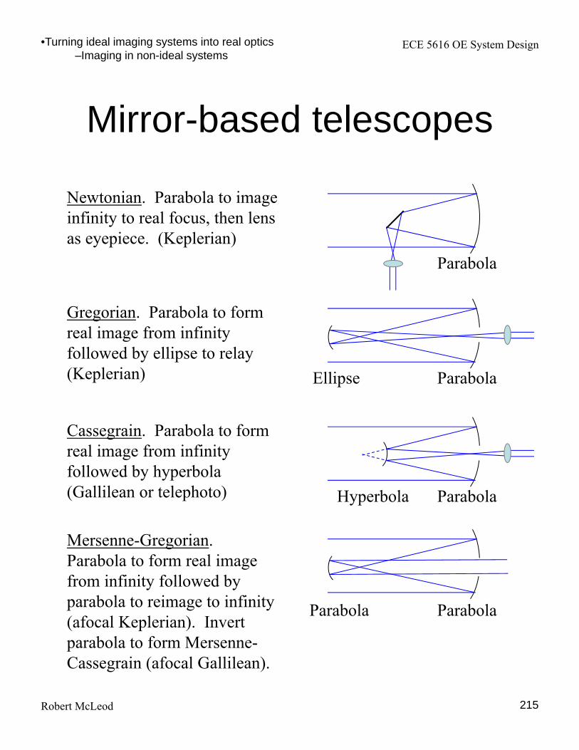
Mirror-based telescopes
•Turning ideal imaging systems into real optics–Imaging in non-ideal systems
Newtonian. Parabola to image infinity to real focus, then lens as eyepiece. (Keplerian)
Parabola
Gregorian. Parabola to form real image from infinity followed by ellipse to relay (Keplerian) ParabolaEllipse
Cassegrain. Parabola to form real image from infinity followed by hyperbola (Gallilean or telephoto) ParabolaHyperbola
Mersenne-Gregorian. Parabola to form real image from infinity followed by parabola to reimage to infinity (afocal Keplerian). Invert parabola to form Mersenne-Cassegrain (afocal Gallilean).
ParabolaParabola
ECE 5616 OE System Design
Robert McLeod 216
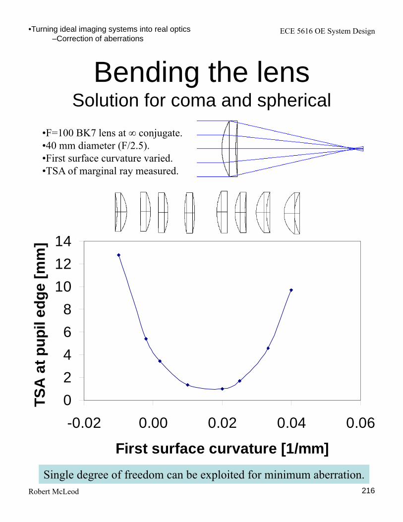
Bending the lensSolution for coma and spherical
•Turning ideal imaging systems into real optics–Correction of aberrations
0
2
4
6
8
10
12
14
-0.02 0.00 0.02 0.04 0.06
First surface curvature [1/mm]
TS
A a
t p
up
il e
dg
e [
mm
]
•F=100 BK7 lens at ∞ conjugate.•40 mm diameter (F/2.5).•First surface curvature varied.•TSA of marginal ray measured.
Single degree of freedom can be exploited for minimum aberration.
ECE 5616 OE System Design
Robert McLeod 217
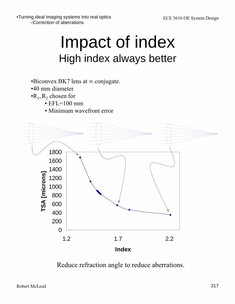
Impact of indexHigh index always better
0
200
400
600
800
1000
1200
1400
1600
1800
1.2 1.7 2.2
Index
TS
A [
mic
ron
s]
•Biconvex BK7 lens at ∞ conjugate.•40 mm diameter •R1, R2 chosen for
• EFL=100 mm• Minimum wavefront error
•Turning ideal imaging systems into real optics–Correction of aberrations
Reduce refraction angle to reduce aberrations.
ECE 5616 OE System Design
Robert McLeod
Computation of primary aberrationsParaxial invariant
218
•Turning ideal imaging systems into real optics– Calculation of aberrations
nnycnuynuun
ucynucynA
uycnuycnA
The paraxial transfer equation can be augmented with the lens maker’s equation
to produce the refraction invariant for the paraxial marginal and chief rays
M&M Chapter 8
These two quantities characterize the bending of an axial (PMR) or edge of field (chief) ray at any surface
nA
nnAuu
nA
nnAuu
111
111
A greater than ~0.5 is the approximate boundary of the non-paraxial regime.

ECE 5616 OE System Design
Robert McLeod
Computation of primary aberrationsSeidel aberration formulae
219
iiiii
k
ii
iIViIII
k
i i
iV
k
i iiIV
k
i i
iiiIII
k
i i
iiiiII
k
i i
iiiI
ucyuyA
SSA
AS
ncHS
n
uhAS
n
uhAAS
n
uhAS
22
1
1
1
2
1
2
1
1
2
1
•Turning ideal imaging systems into real optics– Calculation of aberrations
Seidel sums Wavefront error
Spherical 8IS
Coma 2IIS
Astigmatism 2IIIS
Fieldcurvature
4
IVIII SS
Distortion 2VS
if any A = 0
The (somewhat amazing) conclusion is that one can calculate the third order aberrations from first-order (paraxial) ray tracing of just the marginal and chief rays.
PMRonly
Note
System only

ECE 5616 OE System Design
Robert McLeod
Seidel vs. wavefront vs. ray aberrations
220Zemax manual
n’ and u’ are index and marginal ray angle in the image plane.
•Turning ideal imaging systems into real optics– Calculation of aberrations
un
W
y
W
n
R
y
W
n
R
y
yxW
n
Ry
ppp
pp
,
Motivation for form of transverse ray aberration equations:
…not the index and marginal ray angle at the particular surface.

ECE 5616 OE System Design
Robert McLeod
Petzval (field curvature)
221
•Turning ideal imaging systems into real optics– Calculation of aberrations
4
IVIII SS
Astigmatism Petzval
c1c2n
nH
n
nccH
nc
ncH
ncHS
i iiIV
2
212
212
2
1
2
1
111
1
1
For a single thin (d ~ 0) lens
• So Petzval for a complex lens is approximately proportional to the sum of the powers of the individual elements.
• Thus a lens with all positive elements has unavoidable field curvature.
• Inclusion of negative elements can cancel.
Field curvature is the sum of two terms:

ECE 5616 OE System Design
Robert McLeod
Aberration-free surfaces
222
•Turning ideal imaging systems into real optics– Calculation of aberrations
uuAi 0Marginal ray
Marginal ray along radius = object is at center of curvature
0III SS No spherical or coma
uuAi 0Chief ray
Chief ray along radius = pupil conjugate to center of curvature
0IVIIIII SSS No coma, astigmatism, distortion
0hObject conjugate to surface
0IIIIII SSS No spherical coma, astigmatism
Marginal ray
ECE 5616 OE System Design
Robert McLeod 223
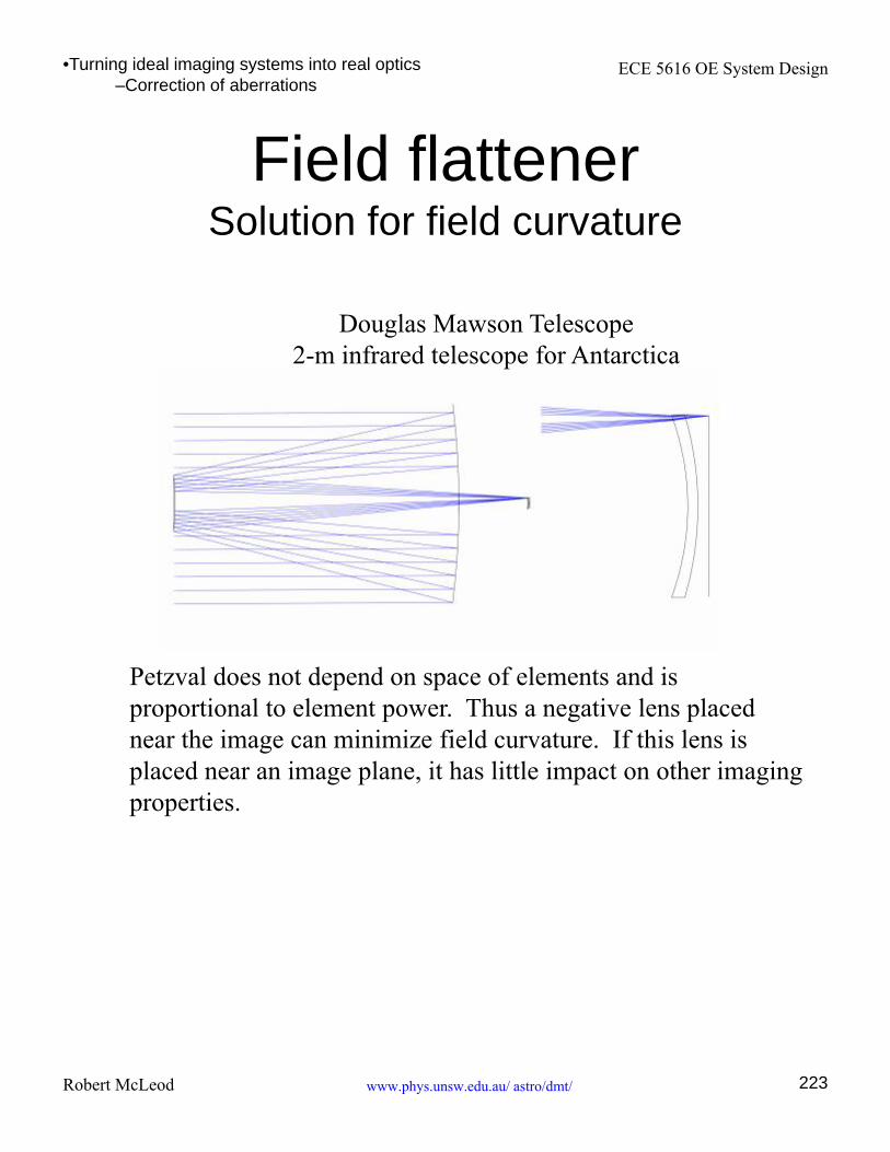
Field flattenerSolution for field curvature
www.phys.unsw.edu.au/ astro/dmt/
•Turning ideal imaging systems into real optics–Correction of aberrations
Douglas Mawson Telescope2-m infrared telescope for Antarctica
Petzval does not depend on space of elements and is proportional to element power. Thus a negative lens placed near the image can minimize field curvature. If this lens is placed near an image plane, it has little impact on other imaging properties.

ECE 5616 OE System Design
Robert McLeod 224
Field lenses
http://www-optics.unine.ch/education/optics_tutorials/field_lens.html
Field lens
A lens placed at the an image plane introduces only field curvature and distortion. We have already used this as a field flattener. Another important use is the field lens, as shown below. • Magnification and other paraxial imaging properties unchanged.• Vignetting significantly altered• Often used when total OD is constrained (e.g. eyepieces)• Lens is at an image plane, thus is very sensitive to dust or scratches.
No field lens
•Turning ideal imaging systems into real optics–Correction of aberrations
ECE 5616 OE System Design
Robert McLeod
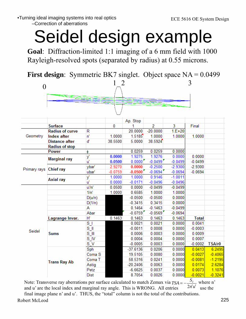
Seidel design example
225
•Turning ideal imaging systems into real optics–Correction of aberrations
Goal: Diffraction-limited 1:1 imaging of a 6 mm field with 1000 Rayleigh-resolved spots (separated by radius) at 0.55 microns.
0 1 2 3First design: Symmetric BK7 singlet. Object space NA = 0.0499
Note: Transverse ray aberrations per surface calculated to match Zemax via where n’ and u’ are the local index and marginal ray angle. This is WRONG. All entries use the final image plane n’ and u’. THUS, the “total” column is not the total of the contributions.
un
STSA I
2
ECE 5616 OE System Design
Robert McLeod
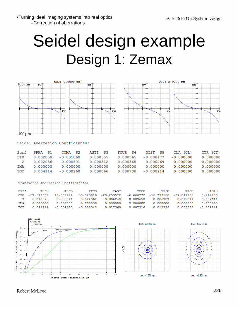
Seidel design exampleDesign 1: Zemax
226
•Turning ideal imaging systems into real optics–Correction of aberrations
100 m
-100 m

ECE 5616 OE System Design
Robert McLeod
Spherical aberration of slab at focus
227
•Turning ideal imaging systems into real optics–Correction of aberrations
4
022
0
111NA
t
nnnr
TSA
t
n nuth
nunu
unA
0
4
022
0 8
111
8
1
r
TSANA
t
nnn
Wspherical
What is SA due to focusing into slab?
0rTSA
Snell’s law
Paraxial invariant of plane
0r
TSA
0W
81
641
641
181
1
181
81
81
8
SR
95.99.
99.
95.
ECE 5616 OE System Design
Robert McLeod
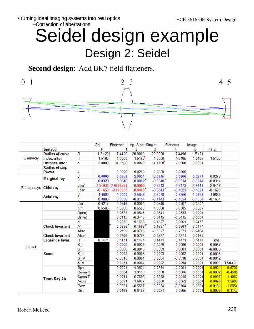
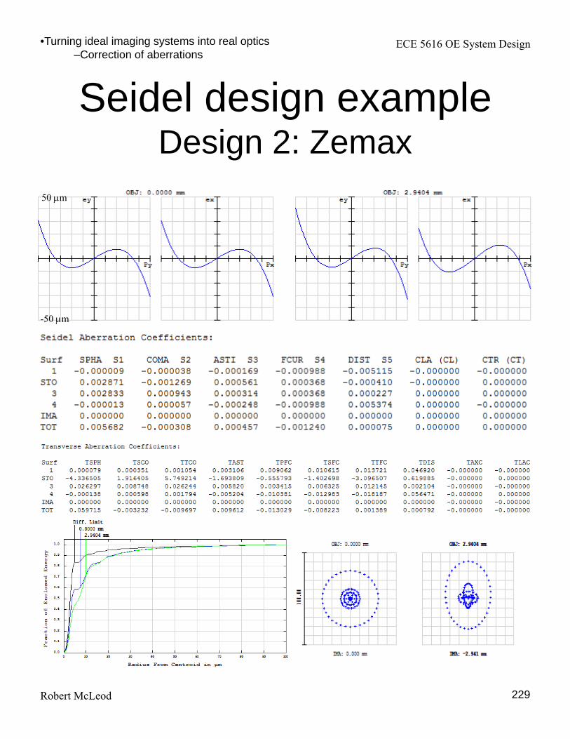
Seidel design exampleDesign 2: Seidel
228
Second design: Add BK7 field flatteners.
0 2 31 4 5
•Turning ideal imaging systems into real optics–Correction of aberrations
ECE 5616 OE System Design
Robert McLeod
Seidel design exampleDesign 2: Zemax
229
50 m
-50 m
•Turning ideal imaging systems into real optics–Correction of aberrations

ECE 5616 OE System Design
Robert McLeod 230
Symmetrical systems
No coma or distortion. Reduces them for M ≠1.
2 mm
2 mm
SA+FC+AST
SA+FC+AST+COMA
•Turning ideal imaging systems into real optics–Correction of aberrations
SA+AST
Asymmetrical system
Symmetrical system
Symmetrical system + best form lenses +
field flatteners200 um
SA
SA
SA
0VII SSSums linear in = 0.A

ECE 5616 OE System Design
Robert McLeod
Aplanatic condition
231
•Turning ideal imaging systems into real optics–Correction of aberrations
0/ nu
0IIIIII SSS No spherical, coma or astigmatism
Higher-order spherical and coma also zero.
Since n and n´ >0, u and u´ must have same sign and thus one of object or image must be virtual.
Q: So what’s it good for? A: Changing NA with minimum aberrations.
The solid immersion lens, Kino, ICOSN ‘99
http://www.optics-online.com/acp.asp
Aplanatic meniscus. One surfacehas A = 0, second is aplanatic, sono spherical or coma, minimalastigmatism. Add an aplanaticmeniscus to an achromat tochange the NA by factor of n´/n
Solid immersion lens. Partialsphere, often of high indexmaterial (diamond, GaP). Left isA=0, increases NA by n. Right is“superSIL”, aplanatic condition,increases NA by n2
ECE 5616 OE System Design
Robert McLeod 232
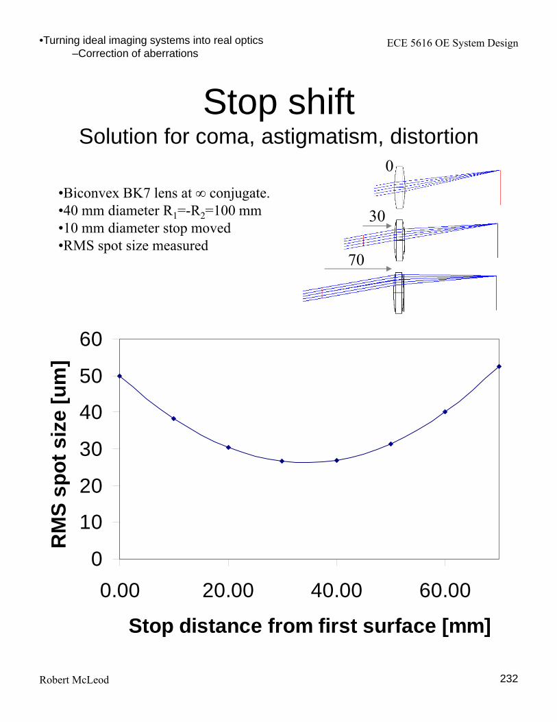
Stop shiftSolution for coma, astigmatism, distortion
0
10
20
30
40
50
60
0.00 20.00 40.00 60.00
Stop distance from first surface [mm]
RM
S s
po
t s
ize
[u
m]
•Biconvex BK7 lens at ∞ conjugate.•40 mm diameter R1=-R2=100 mm•10 mm diameter stop moved•RMS spot size measured
0
30
70
•Turning ideal imaging systems into real optics–Correction of aberrations