•design of ideal imaging syst ems with geometrical optics...
TRANSCRIPT

ECE 5616 OE System Design
Robert McLeod 106
Optics of finite sizeIntroduction
•Design of ideal imaging systems with geometrical optics–Finite optics: stops, pupils, and windows
• Up to now, all optics have been infinite in transverse extent. Now we’ll change that.
• Types of apertures: edges of lenses, intermediate apertures (“stops”).
• Two primary questions to answer:– What is the angular extent (NA) of the light that
can get through the system. “Aperture” = largest possible angle for object of zero height. Depends on where the object is located.
– What is the largest object that can get through the system = “Field”. At the edge of the field, the angular transmittance is one half of the on-axis value.
• Will find each of these with two particular rays, one for each of above.
• Will find two specific stops, one of which limits aperture and one which limits field.
• The conjugates to these stops in object and image space are important and get their own names.
• Finally, this will allow us to understand the total power efficiency of the system.

ECE 5616 OE System Design
Robert McLeod 107
The aperture stopand the paraxial marginal ray.
•Design of ideal imaging systems with geometrical optics–Finite optics: stops, pupils, and windows
Aperture stop
Paraxial marginal ray(PMR)
D
A diaphragm that is not the aperture stop
• Launch an axial ray, the paraxial marginal ray, from the object. • Increase the ray angle until it just hits some aperture.• This aperture is the aperture stop.• The sin of is the numerical aperture. • The aperture stop determines the system resolution, light transmission efficiency and the depth of field/focus.

ECE 5616 OE System Design
Robert McLeod 108
PupilsThe images of the aperture stop
The entrance (exit) pupil is the image of the aperture stop in object (image) space.
O’Shea 2.4, M&M chapter 5
•Design of ideal imaging systems with geometrical optics–Finite optics: stops, pupils, and windows
• Axial rays at the object (image) appear to enter (exit) the system entrance (exit) pupil.• When you look into a camera lens, it is the pupil you see (the image of the stop).• Both pupils and the aperture stop are conjugates.• A ray launched into the exit pupil will make it through the aperture stop – this is a
major reason the pupil is a useful concept.
Aperture stop and entrance pupil
Paraxial marginal ray(PMR)
Exit pupil
D
A diaphragm that is not the aperture stop

ECE 5616 OE System Design
Robert McLeod 109
WindowsImages of the field stop
•Design of ideal imaging systems with geometrical optics–Finite optics: stops, pupils, and windows
Aperture stopField stop
• Launch an axial ray, the chief ray, from the aperture stop. • Increase the ray angle until it just hits some aperture.• This aperture is the field stop.• The angle of the chief ray in object space is the angular field of view. • The height of the chief ray at the object is the field height.• The chief ray determines the spatial extent of the object which can be viewed. When that object is very far away, it is convenient to use an angular field of view.• When the field stop is not conjugate to the object, vignettingoccurs, cutting off ~half the light at the edge of the field.
ECE 5616 OE System Design
Robert McLeod 110
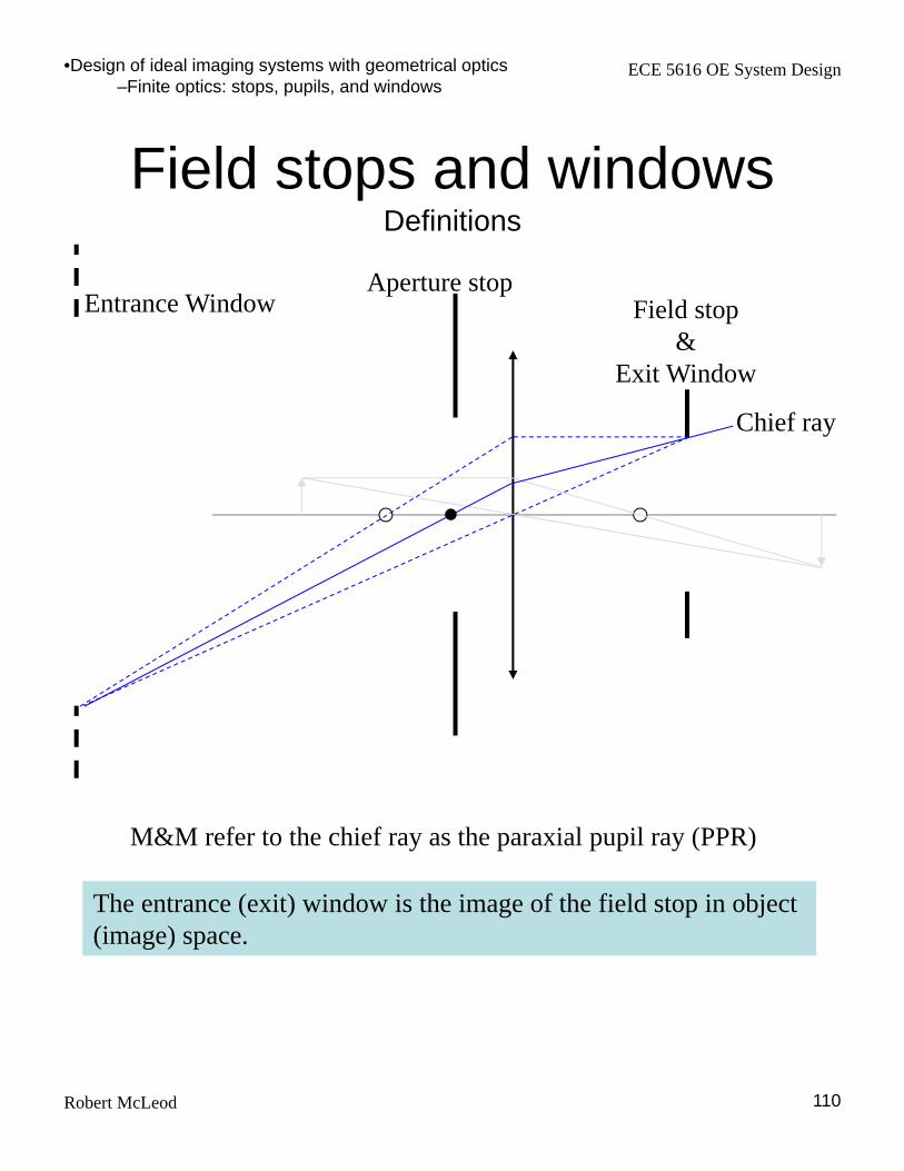
Field stops and windowsDefinitions
The entrance (exit) window is the image of the field stop in object (image) space.
•Design of ideal imaging systems with geometrical optics–Finite optics: stops, pupils, and windows
M&M refer to the chief ray as the paraxial pupil ray (PPR)
Aperture stopField stop
&Exit Window
Chief ray
Entrance Window

ECE 5616 OE System Design
Robert McLeod 111
Numerical apertureThe measure of angular bandwidth
sinNA n Definition of numerical aperture.Note inclusion of n in this expression.
NA is the conserved quantity in Snell’s Law because it represents the transverse periodicity of the wave:
NAnfk xx00
2sin
2 2
F
Dpupil 2 Paraxial approximation
pupilD
FNA
F
2
1# Definition of F-number
Paraxial approximation
Therefore NA/0 equals the largest spatial frequency that can be transmitted by the system.Note that NA is a property of cones of light, not lenses.
•Design of ideal imaging systems with geometrical optics–Finite optics: stops, pupils, and windows
#6.00 FNA
r Radius of Airy disk

ECE 5616 OE System Design
Robert McLeod 112
Effective F# Lens speed depends on its use
•Design of ideal imaging systems with geometrical optics–Finite optics: stops, pupils, and windows
D
D
Infinite conjugate condition
D
fNA
F
2
1#
#1
1#
FMD
Mf
D
tF i
Finite conjugate condition
t’
or M
o
i
NANA
MNANA11
1
#1
1#
1
1
FD
f
D
tF
M
Mo
t
ECE 5616 OE System Design
Robert McLeod 113
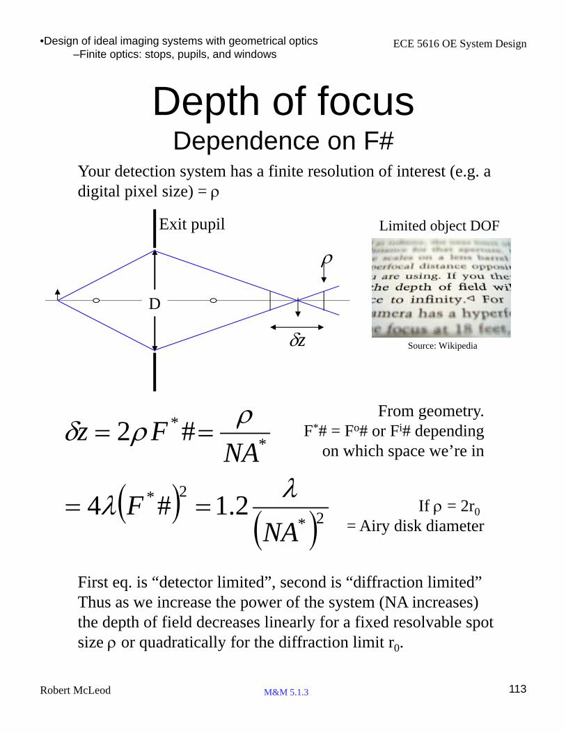
Depth of focusDependence on F#
D
z
2*
2*
**
2.1#4
#2
NAF
NAFz
First eq. is “detector limited”, second is “diffraction limited”Thus as we increase the power of the system (NA increases) the depth of field decreases linearly for a fixed resolvable spot size or quadratically for the diffraction limit r0.
•Design of ideal imaging systems with geometrical optics–Finite optics: stops, pupils, and windows
M&M 5.1.3
From geometry.F*# = Fo# or Fi# depending
on which space we’re in
If = 2r0
= Airy disk diameter
Exit pupil
Your detection system has a finite resolution of interest (e.g. a digital pixel size) =
Limited object DOF
Source: Wikipedia

ECE 5616 OE System Design
Robert McLeod 114
Hyperfocal distanceImportant for fixed-focus systems
•Design of ideal imaging systems with geometrical optics–Finite optics: stops, pupils, and windows
D
z
Entrance pupil
Depth of FieldNote how each focus falls within the acceptable blur
The object distance which is perfectly in focus on the detector is defines the nominal system focus plane.
When this plane is positioned such that the far point goes to infinity, then the system is in the “hyperfocal” condition and the nominal focus plane is called the “hyperfocal distance”.
This is very handy for fixed focus cameras – you can take a portrait shot (if the person is beyond the near point) out to a landscape and not notice the defocus.
Far
poi
nt
Nea
r po
int
Nom
inal
foc
us

ECE 5616 OE System Design
Robert McLeod 115
VignettingLosing light apertures or stops
•Design of ideal imaging systems with geometrical optics–Finite optics: stops, pupils, and windows
Take a cross-section through the optical system at the plane of any aperture. Launch a bundle of rays off-axis and see how they get through this aperture:
Aperture radius = a
Ray bundle of radius y
Unvignetted Central ray height, y
yya
Aperture radius = a
Ray bundle of radius y
Fully vignettedCentral ray height, y
yya
Example of vignetting

ECE 5616 OE System Design
Robert McLeod 116
Pupil matchingOff-axis imaging & vignetting
f1f2
A.S.
Exit pupil of telescope (image of A.S. in image space) matches entrance pupil of following instrument (eye).
•Design of ideal imaging systems with geometrical optics–Finite optics: stops, pupils, and windows
Good place for a field stop if the object is at infinity.
Note that the entrance pupil in the system above will appear to be ellipsoidal for off-axis points. Thus even in this well-designed, aberration-free case, off-axis points will not be identical on axis.
Vignetting: Further, we might find extreme rays at off-axis points are terminated. This loses light (bad) but also loses rays at extreme angles, which might limit aberrations (good).
f1
f2
A.S.

ECE 5616 OE System Design
Robert McLeod 117
Telecentricity
f1 f2
Aperture stop
•Design of ideal imaging systems with geometrical optics–Finite optics: stops, pupils, and windows
In a telecentric system either the EP or the XP is located at infinity. The system shown above is doubly telecentric since both the EP and the XP are at infinity. All doubly telecentric system are afocal.
When the stop is at the front focal plane (just lens f2 above) the XP is at infinity and slight motions of the image plane will not change the image height.
When the stop is at the back focal plane (just lens f1 above) the EP is at infinity and small changes in the distance to the object will not change the height at the image plane.
Telecentricity is used in many metrology systems.

ECE 5616 OE System Design
Robert McLeod
Analyzing an optical system
1. Specify the system via distances, component locations, focal length, and clear apertures.
2. Run a marginal ray using a y-u trace
3. Find the aperture stop (calculate the ratio of clear aperture to ray height (smallest r/yk is aperture stop)
4. Run a chief ray trace
5. Calculate as in step 3 above to find field stop
6. Find locations of pupils and windows via thin lens equations if small # of elements or yu/matrix methods if large #.
7. Sizes of pupils can be determined by taking the slope angle of the chief ray at the aperture stop and dividing by the image and object space slope angles of that ray to get the magnification of the aperture stop in image and object space, respectively. Multiplying the aperture stop size by the magnification gives the exit and entrance pupil sizes. (Optical invariant is the basis).
A full report of a optical system contains: image location and magnification, the location of stops, pupils, and windows, the effective focal length of the system, F/#, and its angular field of view.
118
•Design of ideal imaging systems with geometrical optics–Finite optics: stops, pupils, and windows

ECE 5616 OE System Design
Robert McLeod 119
Detailed exampleHolographic data storage
objec t
x y
referenc e
S LM
Holographic
M ateria l
R efe rence
Telescope
B .S .
Ga lvo
Mi rror
C orrel ation
Im a ging Le ns C C D
SLMImaging
Lens
Linear CCD
Object beam shutter
We’re going to design the imaging path
•Design of ideal imaging systems with geometrical optics–Example

ECE 5616 OE System Design
Robert McLeod 120
1 to 1 imagingAperture in Fourier plane
•Design of ideal imaging systems with geometrical optics–Example
DSLM=10 mmp = 10 m
SLMLens
Aperture CCD
DLens=10 mmf = 20 mm
DAp= 2 mm DCCD=10 mm
40 mm 20 mm 20 mm
Material
Fourier diffraction calculation for a random pixel pattern.S
LM
CC
D
Lens

ECE 5616 OE System Design
Robert McLeod 121
Finding the aperture stopTrace the paraxial marginal ray (PMR)
DSLM=10 mmp = 10 m
SLM Lens Aperture CCD
DLens= 10 mmf = 20 mm
DAp= 2 mm DCCD=10 mm
k
kk
k
k
u
yt
u
y
10
1
1
1
k
k
kk
k
u
y
u
y
1
01
Surf 0 1 1’ 2 3
y 0 .4 .4 .2 0
u’ .01 .01 -.01 -.01 -.01
y/r .08 .08 .2
PMR
y0 2 2 1 0
PMR
u’.05 .05 -.05 -.05 -.05
Aperture stop
•Design of ideal imaging systems with geometrical optics–Example
0 1 2 3

ECE 5616 OE System Design
Robert McLeod 122
What does the aperture stop do?Limits the NA of the system
8
1
)2(20
5
)1(
2/*
Mf
DNA
What is the lens effective NA?
However we have stopped the system down to NA = 2/40=1/20
*NA
NA
•Design of ideal imaging systems with geometrical optics–Example
Pixel size = 10 m 20
1
10
5.
pNApix
The aperture stop thus:1. Determines the system field of view2. Controls the radiometric efficiency3. Limits the depth of focus4. Impacts the aberrations5. Sets the diffraction-limited resolution
rAS= 1 mmy=2 mm
40 mm

ECE 5616 OE System Design
Robert McLeod 123
Find the entrance pupil(image of aperture stop in object space)
•Design of ideal imaging systems with geometrical optics–Example
Aperture stop and exit pupil
ftt
111
10
20
11
20
1
1
t
1t
Entrance pupil
What’s that mean? If the entrance pupil is at infinity, then every point on the object radiates into the same cone:

ECE 5616 OE System Design
Robert McLeod 124
Find the field stopTrace the chief ray (PPR)
DSLM=10 mmp = 10 mm
SLM Lens Aperture CCD
DLens= 10 mmf = 20 mm
DAp= 2 mm DCCD=10 mm
k
kk
k
k
u
yt
u
y
10
1
1
1
k
k
kk
k
u
y
u
y
1
01
Surf 0 1 1’ 2 3
y .2 .2 .2 0 -.2
u’ 0 0 -.01 -.01 -.01
y/r .04 .04 0
PPR
y5 5 5 0 -5
Field stop
•Design of ideal imaging systems with geometrical optics–Example
Entrance and exit windows at field stop (since it is lens).

ECE 5616 OE System Design
Robert McLeod 125
Required lens diameterAnd why windows should be at images
•Design of ideal imaging systems with geometrical optics–Example
pixNA
Object vignetted at edges
• Now the camera is the field stop and the entrance window is the SLM.• The optical system now captures the same light from each SLM pixel and it can be adjusted for all pixels via the aperture stop. • Independently, we can adjust the field size.
M&M 5.1.8
125222 yyD
Note that the extreme marginal ray makes the same angle with the chief ray (PPR) as the paraxial marginal ray (PMR) makes with the axis. Thus to fit the extreme marginal ray through an aperture, we require:

ECE 5616 OE System Design
Robert McLeod 126
Thicken the lensesGaussian design
DSLM=10 mmp = 10 m
SLM
Lens
Aperture CCD
DLens=12 mmF = 20 mm
DAp= 2 mm DCCD=10 mm
40 mm 20 mm 20 mm5mm
P P’
•Design of ideal imaging systems with geometrical optics–Summary

ECE 5616 OE System Design
Robert McLeod 127
Optical invariantaka Lagrange or Helmholtz invariant
•Design of ideal imaging systems with geometrical optics–Finite optics: stops, pupils, and windows
yunun
ynuun
Write the paraxial refraction equations for the marginal ray (PMR) and chief or pupil ray (PPR):
yuyunyuyun With a bit of algebra:
yuyunH So
is conserved.
At the object (or image) of limited field diameter L:
angleray maximum field, of edge ,0 uyy
spotsNL
r
LNAynuH
226.
2 0
Thus we have found the information capacity of the optical system, aka the space-bandwidth product:
HNspots 2
Where “spots” here are
separated by their diameter, 2r0

ECE 5616 OE System Design
Robert McLeod
Typical number of resolvable spotsA survey of >3000 optical designs
128
•Design of ideal imaging systems with geometrical optics–Finite optics: stops, pupils, and windows
Design Efficiency of 3188 Optical Designs, Proc. of SPIE Vol. 7060 70600S-1
diameterSpot
diameter field ImagespotsN
So, for a well-optimized system up to ~ 4 elements, we have1200 spots/element, monochromatic systems with all-spherical elements1600 spots/element, monochromatic systems with some aspheric elements1100 spots/element, polychromatic systems with all-spherical elements1100 spots/element, polychromatic systems with some aspheric elements

ECE 5616 OE System Design
Robert McLeod 129
Optical invariantfor the holographic storage example
pix
SLM
SLM
spots
N
p
D
pD
NAy
HN
0
0
0
00
0
2
2
•Design of ideal imaging systems with geometrical optics–Summary
Definition of optical invariant
Stopped-down NAStopped-down NA
So we have correctly designed this system to transmit the proper number of resolvable spots.

ECE 5616 OE System Design
Robert McLeod
Counting resolvable waves in the pupil
130
•Design of ideal imaging systems with geometrical optics–Summary
X.P.
xIP
E
r0
fXP
E
DXP
xXP
rXP
E
-rXP Fourier Transform
XP
XP
XP
XP
Dd
dDd
NA
d
r
D
D
25.
5.
/1
/1
0
r0
d
fz1
fxp
XPD
1
XPD
1
Remove quadratic phase of converging wavefront. Remainder is rect with linear phase (=tilt) whose FT is a shifted sinc in the image plane.
E at image plane
xXP
rXP
-rXP
Wavefronts in AS
z
Phase in AS
K-space (what is in AS?) Spectrum in AS
One of tilt in AS is equivalent to shift of DL radius in image plane.