turbo condensing oil boiler installation & user manual
TRANSCRIPT

OIL CONDENSING BOILER INSTALLATION AND USER MANUAL
INSTALLATION & USER MANUAL www.krb.co.kr 1
Types
TURBO CONDENSING - 13
TURBO CONDENSING - 17
TURBO CONDENSING - 21
TURBO CONDENSING OIL BOILER
INSTALLATION & USER MANUAL

OIL CONDENSING BOILER INSTALLATION AND USER MANUAL
INSTALLATION & USER MANUAL www.krb.co.kr 2
Introduction ................................................................................................................................. 4
Features …………………………………………………………………………………………………………… 6
1. Warranty terms and conditions ……...…………………….......................................................... 7
1.1. General precautions ..................................................................................................................................... 7
1.2. Precautions for operation ......................................................................................................................... 8
1.3. Cautions for operation ……………….…………………………………………………………….…………………… 9
1.4. Warranty terms and conditions ............................................................................................................. 10
2. Product Structure ..................................................................................................................... 11
2.1. Appearance and components ……………………………………………………………………………………... 11
2.2. Burner construction ……………………………………………………………………………………....................... 12
2.3. Other components ………………………………………………………………………………………………………. 13
3. Product Installation …………………………………………………………………………………….…. 14
3.1. Location ........................................................................................................................................................ 14
3.2. General cautions for piping ................................................................................................................. 15
3.3. Product dimensions and pipeline ..................................................................................................... 16
3.4. Piping ............................................................................................................................................................. 17
3.5. Flue installation .......................................................................................................................................... 18
3.5.1 General flue installation............................................................................................................ 18
3.5.2 Installation in the ceiling …………………………………………...……………………………………. 19
3.5.3 General cautions for flue installation ………………………………………..………………..… 20
3.6. Condensate drainage ………………………………………………..………………………….…..………………… 21
3.6.1 Connecting neutralizer ……………………………………………………………….………………… 21
3.6.2 Replenishing water to neutralizer …………………………………………………..……………… 22
3.7. Fuel line ……………………………………………………………………………...………………….…..………………. 23
3.7.1 Fuel tank installation ………………………………………………………………………………………… 23
3.7.2 Oil filter and fuel line installation ……………….……………………………………………………. 24
3.7.3 Fuel line air venting ………………………………………………………………………………………… 25
3.8. Electric wiring ............................................................................................................................................ 26
3.8.1 General cautions for electric wiring ………………………..………………………………………… 26
3.8.2 Wiring Diagram ……………………………………………………………..………………………….……….. 27
3.8.3 Connector cable structure ……………………………………………………………..………………….. 28
3.9. Room temperature controller installation ……………………………………….………….……………… 31
3.10. Checklist after installation …………………………………………………………….….…………….…………. 32
3.11. Boiler commissioning …………………………………………………………………...……………………….….. 33
4. Product Operation Method ..................................................................................................... 34

OIL CONDENSING BOILER INSTALLATION AND USER MANUAL
INSTALLATION & USER MANUAL www.krb.co.kr 3
4.1. Room temperature controller components ……………………………..………..……………………… 34
4.2. Heating function .......................................................................................................................................... 35
4.2.1 Operation modes ……………………………………………………………………………..……………… 35
4.2.2 Indoor mode operation …………………………………………………………..……………..……….. 36
4.3 Reservation ……………………………………………………………………………………………..…………………….. 37
4.3.1 Execute reservation …………………………………………………………………………………………. 37
4.3.2 Setting up timer function (min) …………………………………………………………………… 37
4.4 Outing (leave) function ........................................................................................................................... 38
4.4.1 Enable leave function ……………………..………………………………………………………………. 38
4.5 Bath operation …………………………………………………………………...……………………………………… 39
4.5.1 Run bath operation …………………………………………………………………………………………. 39
4.5.2 Setting up hot bath water temperature ………………….……………………………………… 39
5. Product Maintenance .............................................................................................................. 40
5.1. Boiler cleaning …………….………………………………………………………………...………………………… 40
5.2 Burner cleaning ………………………………………………………………………….…………………….……….. 41
5.3. Cleaning neutralizer ………………………………………………………………..………………….…………….. 43
6. Troubleshooting ……………………………………………………………………………………………. 44
7. Product Disposal ........................................................................................................................ 45
8. Technical Data .......................................................................................................................... 46
8.1. Basic specification ………………………………………………….…………………..…………..……………… 46
8.2. Specification for combustion ………………………….…………………………..…………..……………… 47
8.3. Spare parts .………………………………………………………………………………....………………..………… 48
8.4. Water temperature sensor table ………………………………………………………………………….….. 49
8.5. Time chart ……………………………………………………………………………………………………….………. 50
8.6 Burner fan motor performance curve …………………………………………………...…………………….. 52

OIL CONDENSING BOILER INSTALLATION AND USER MANUAL
INSTALLATION & USER MANUAL www.krb.co.kr 4
Introduction
Dear Customers;
Thank you very much for selecting out condensing oil boiler.
Designed and manufactured with advanced technology of Kiturami Boiler, top quality stainless
steel parts, the product ensures a long life cycle. Specially designed Hi-Fin structure reduced
burner load by about one half with higher thermal efficiency.
Please read this manual carefully to operate the product at highest design performance to
achieve optimal heating performance.
Please keep children away from the product while it is in operation, and abide by the
maintenance instructions described in this manual. Once again, we would like to express our
thanks to you!
Modification of the document
The content of this document is subject to change without written prior notice to improve the
product. It is prohibited by the Intellectual Properties Law to copy or reproduce all or a part of
this document without prior written consent.
Using this manual
Please keep this manual at a safe and easily accessible place.
It this manual is lost, damaged or become illegible, request a new one to your local agency or
dealer of the product.
In this manual, the important information which requires special caution is printed in bold type.
The descriptions indicating cautious reference to other paragraph or additional information are
printed in Italic type.

OIL CONDENSING BOILER INSTALLATION AND USER MANUAL
INSTALLATION & USER MANUAL www.krb.co.kr 5
Symbols used in this document
Failure to comply the instruction marked with this symbol can lead to
serious personal injuries or even death, or damage to the product. Please
read the message carefully and observe the instruction.
This symbol underlines the information important for proper operation of
the boiler. Failure to comply the instruction can lead to malfunction or
deteriorated performance.
Matters must be observed.
Other special symbols
Caution for electric shock
Don't touch
No heat source
The system must be grounded (earthed).

OIL CONDENSING BOILER INSTALLATION AND USER MANUAL
INSTALLATION & USER MANUAL www.krb.co.kr 6
Features
Energy saving function
The room temperature controller is built-in with the digital control functions
including At Home, Reservation, Outing and Bathing for the operation modes
optimized for the purpose. This function improves energy efficiency.
Self diagnosis function
Problem or failure of function will be notified by flickering check lamp and the
failure code (figure) displayed on the screen.
Ultra-high efficiency boiler
Specially designed Hi-Fin structure reduced burner load by about one half, and
condensing technology provides higher thermal efficiency.
Automatic control system
All the basic functions including At Home, Reservation, Outing and Bathing modes,
fault diagnosis, anti-freezing, and circulation pump seizure prevention are
automatically controlled.
Condensate neutralizer
The condensate generated during operation has to be neutralized before entering
drainage. This product neutralizes condensate to pH 4~6.
High quality stainless steel material
Major parts are made of high quality stainless steel to provide durability against
seawater and oceanic climate.

OIL CONDENSING BOILER INSTALLATION AND USER MANUAL
INSTALLATION & USER MANUAL www.krb.co.kr 7
1. Warranty terms and conditions
1.1. General precautions
Installation, electric wiring, commissioning and maintenance works must be carried
out by qualified personnel.
Boiler installation work must be carried out in compliance with the national or
regional laws and regulations.
This manual provides for the installation, setting, operation and maintenance of the
product in addition to basic information.
It is prohibited to operate this product by any person who comes under any one of
the followings: children having limited physical, sensible or mental capacity, persons
without knowledge about the product and not trained to operate the point of
departure form a safety supervisor.
The instructions provided in this manual must be observed to use the product and
installed electronic devices correctively and to prevent safety accident.
Please read and understand this manual carefully before operating the product.
The boiler must not be used for any other purpose than the intended purpose.
Operating the boiler for an unintended purpose may lead to dangerous situation.
Do not step on the boiler or use the boiler as a support.
Do not hang out wash near the boiler or flue for drying. Wash hangers or similar
devices must be kept away from the boiler by an appropriate distance. Otherwise, fire
may break out.
The user shall take all the responsibilities for appropriate use of the product. The
manufacturer does not take any responsibilities neither civil nor penal.
Unauthorized modification is prohibited. Failure of using genuine parts can lead to
dangerous situation for the user. This company does not take any responsibilities neither
civil nor penal.
The boiler flue tubes are very hot. Do not touch the flue tubes before the boiler has
been cooled down sufficiently or without wearing safe, insulating gloves.
Do not touch the boiler with wet hands, since it is an electrical equipment. Disconnect
power supply cable before doing any work with the boiler.
Turn off main power switch or disconnect power cord before conducting a maintenance
work.
The boiler must be grounded with an effective conductor.

OIL CONDENSING BOILER INSTALLATION AND USER MANUAL
INSTALLATION & USER MANUAL www.krb.co.kr 8
The boiler must be supplied with electric power with appropriate voltage and capacity.
Inappropriate installation or maintenance, not in compliance with the instruction of this
manual can lead to personal injuries and/or loss of properties. In such case, this
company does not take any responsibilities neither civil nor penal.
The appliance is not to be used by children or persons with reduced physical, sensory
or mental capabilities, or lack of experience and knowledge, unless they have been
given supervision or instruction.
children being supervised not to play with the appliance.
If the supply cord is damaged, it must be replaced by the manufacturer. its service
agent or similarly qualified persons in order to avoid a hazard.
1.2. Precautions for operation
The product must be operated in compliance with the applicable laws and
regulations of the nation or region, in addition to the applicable EU standards.
Use only the fuel recommended by the boiler manufacturer. Check that the fuel feed
valve is open before starting the boiler. If fuel is not supplied, the boiler will not start up
and an alarm will be triggered.
Check that the boiler is filled up with boiler water. If the boiler water level is lower than
the sensor level, the check lamp will be lit and ignition will fail.
Open at least one of the hot water distributor valves while operating the boiler. If all the
valves of the distributor are closed during operation, the boiler can be damaged or
catch fire due to overheating.
Check if the flue tubes are not properly connected, or any joint is damaged by
condensate or cracked. If the flue tubes are not properly connected and sealed, the
exhaust gas could penetrate into the room and cause suffocation by carbon monoxide
(CO).
Store the boiler at a dry place, avoiding extremely low temperature.
It is not recommended to install the boiler contacting the floor or ground. The floor
made with a combustible material must be insulated properly.
Do not store portable gas container, thinner, oil, or other inflammable materials in the
boiler room. Otherwise, fire may break out. (Inflammable materials: methane, acetylene,
propane, hydrogen sulfide, water gas, coal gas, gasoline, acetone, toluene, and other
combustible liquids whose flash point is below 30ºC).
Check that the power supply complies with the rated voltage (AC 230V 50Hz) in the
name plate. Check that the hot water circulation water has sufficient capacity.

OIL CONDENSING BOILER INSTALLATION AND USER MANUAL
INSTALLATION & USER MANUAL www.krb.co.kr 9
1.3. Precautions for boiler operation
Shut down the boiler in case of failure or malfunction.
Lightning can damage the boiler. Pull out power cord plug if lightning strikes, for safety.
Do not wash the inside of the boiler with water. Water in boiler can cause short-circuit
resulting in electric shock.
Do not install other device such as heater wire or heater rod in the boiler pipeline to
prevent freezing. Such additional device can cause injury to the user or damage to
properties.
If you leave home for a long time in winter, the boiler may be damaged by freezing. So,
keep the boiler power ON. The pipes exposed to cold weather may freeze, damaging the boiler.
Exposed pipes must be insulated in cold regions/climate.
Do not clean the boiler and room temperature controller with wet cloth. Otherwise,
electric shock may occur, or internal parts may be deteriorated or failed due to the
infiltration of moisture.
Do not contact the flue tube or pipeline during operation because they are very hot.
Failure to comply with this can lead to burn of the user.
Be cautious when opening the hot water tab, as the water is very hot. Especially,
children or the old whose skin is liable to burn must not use the hot water without help
of a guardian.
Do not disassemble/assemble the boiler. Otherwise, the boiler may get out of order, or
electric shock, fire, or gas accident may occur. Furthermore, thermal efficiency may be
deteriorated and fuel consumption may be increased due to incomplete combustion.
Please contact a service center if repair is necessary.
For safe and trouble-free operation of the boiler, ask your nearest A/S center for regular
inspection at least once a year.

OIL CONDENSING BOILER INSTALLATION AND USER MANUAL
INSTALLATION & USER MANUAL www.krb.co.kr 10
1.4. Warranty terms and conditions
KITURAMI guarantees the boiler, excluding the components which are subject to normal, for a
period of 1 years from the date of purchase, as proved by a supporting document which gives
the name of the vendor and the date on which the sale took place. The warranty is based on the
filled-in Warranty Card and applicable to the product returned within 8day form the date of
selling, on the condition that the product is installed and tested by a skilled expert in accordance
with the detailed description in the manual supplied wit the product. The term "Warranty" means
replacement or repair provided free of charge for the part(s) recognized to be defective at the
earlier stage of use and the defect was caused in the course of manufacturing.
1.4.1. Limitation
The warranty term, as stated earlier, is not applicable to the electric and electronic parts and
components after one 1 year from the date of purchase. The warranty terms and conditions are
not applicable to the consumable parts, such as gaskets and glass, and the removable parts in
combustion chamber. Replaceable parts are guaranteed for the remaining period beginning from
the date of purchase.
1.4.2. Exemption
Discoloration or crack in the coating of the painted parts or ceramic parts are inherent
characteristics of the materials, therefore, such minor defects do not form the basis for claim.
This company does not take any responsibilities for the problems caused by negligence, mistake,
inappropriate maintenance, and installation works not in compliance with the instructions
specified by this company. Please refer to the pertinent descriptions in this manual.
This company does not take any responsibilities for any direct or indirect loss, damage or injuries
to people, animal, or properties of the user caused by failure to comply with the instructions,
especially, cautions for installation, operation and maintenance provided in this manual.
If the performance of the product does not meet your expectation, please contact your local
dealer or importer: The losses or damages caused by careless handling or in the course of
transportation are excluded from the scope of warranty.
Please refer to and observe the instructions related to the installation and p[n of the product.
Any losses caused by product modification, force majeure, electric spark, fire, or defective electric
devices, or by insufficient or incorrect instruction provided by the manufacturer on the product
maintenance are excluded from the scope of warranty.
Claims
Any claim raised in compliance with the warranty terms and conditions must be transmitted
to the technical service team via your dealer. This company does not take any
responsibilities for any damage or loss caused by incorrect use of the product or accessories
or by unauthorized modification. Use only genuine spare parts.

OIL CONDENSING BOILER INSTALLATION AND USER MANUAL
INSTALLATION & USER MANUAL www.krb.co.kr 11
2. Product Structure
2.1. Appearance and components
Fig. 2.1 Front view of the boiler
Fig. 2.2 Rear view of the boiler
1 A/S cover 12 Oil burner 22 Heat exchanger 33 Control unit
2 Front casing (upper) 13 Low water level
23 Oil pump 34 Heat exchanger
3 Front casing (lower)
14
Sensor
Expansion tank
24 Neutralizer support
4 Upper cover 25 Baffle plate 35 Burner gasket
5 Exhaust flue connector 15
16
Circulating pump
Pressure gauge
26 Hot water coil 36 Hood packing
6 Side/rear casing 27 HI-Fin flue pipe 37 Exhaust tube
7 Power switch 17 3Way valve 28 Hot water outlet 38 Flue O-ring
8 Bottom casing 18 Upper hood 29 Hot water inlet 39 Condensate drainage
9 Condensate drain hole 19 Air vent 30 Heating outlet 40 Casing bracket
10 Air pressure switch 20 Thermostat 31 Heating return
11 Ignition transformer 21 Water temp. sensor 32 Air frill

OIL CONDENSING BOILER INSTALLATION AND USER MANUAL
INSTALLATION & USER MANUAL www.krb.co.kr 12
2.2. Burner construction
Fig. 2.3 Exploded view of burner
1 Burner motor 8 Burner upper casing
2 Burner tube 9 Venturi pipe
3 Burner lower casing 10 Primary fan
4 Secondary fan 11 Flame detector
5 Oil nozzle 12 Fan casing
6
7
Nozzle adapter
Ignition rod
13 Air damper

OIL CONDENSING BOILER INSTALLATION AND USER MANUAL
INSTALLATION & USER MANUAL www.krb.co.kr 13
2.3. Other components
Fig. 2.4. Flue set components
Fig. 2.5. Accessories
1 Flue adapter 7 Power cord 13 Oil hose bushing
2 Extending tube 500 mm 8 Condensate drain hose 14 User's Manual
3 Exhaust flue 9 Cleaning brush 15 Room temperature controller
4 Extending tube 300 mm 10 Condensate hose clip 16 Flue tube band
5 Elbow 11 Oil hose
6 Finish material 12 Oil filter

OIL CONDENSING BOILER INSTALLATION AND USER MANUAL
INSTALLATION & USER MANUAL www.krb.co.kr 14
3. Product Installation
3.1. Location
• It is recommended to install the product in a boiler room to prevent exhaust
gas from penetrating into the house.
• Secure sufficient space around the product to enable service and maintenance
work.
• Secure at least 60cm and 40cm of clearance from the wall and ceiling,
respectively.
• If the boiler cannot but be installed outdoor, provide a shelter and heat
insulation for freeze protection.
• Avoid outdoor installation which may cause freezing and/or bad combustion
due to wind or rainfall.
• Avoid the cold/hot air outlet of cooler/heater
• Air intake and exhaust tube (flue) must be provided for uninterrupted air feed
and exhaust.
• The floor under the boiler must be built with incombustible materials.
Fig. 3.1. Schematic view of boiler location
A Min. 60 cm from the ceiling D Boiler room air inlet
B Min. 40 cm from the wall E Boiler room wall
C Min. 5 cm of support (incombustible material) F Boiler room vent

OIL CONDENSING BOILER INSTALLATION AND USER MANUAL
INSTALLATION & USER MANUAL www.krb.co.kr 15
3.2. General cautions for piping
• Connect the pipes with unions or flanges for easy replacement or maintenance,
or line modification in the future.
• Apply thermal insulation to feed water line, hot water line, heating water line,
distributer, and check valve.
• Piping materials must satisfy applicable standard.
• Before connecting the heating and hot water line to the boiler, flush the lines to
remove foreign matters in the lines (thorough cleaning).
• Do not use underground water as the heating water. If using underground water
in the heating system is unavoidable, clean up the pipeline thoroughly.
• Arrange the exposed pipeline in good order and apply thermal insulation.
Vertical lines must be fixed to prevent displacement.
• The foreign matters in the pipeline reduce system efficiency and cause failures.
• Air inside pipeline must be thoroughly removed.
• If the boiler feed water line is connected directly to city water line, install a filter,
pressure regulator valve, check valve, safety valve, and closed type expansion
rank in the incoming line.
• The safety valve and closed expansion tank must have sufficient capacities.
• The hot water line pipes must be coated product or stainless steed products.
• The capacity of the circulation pump must be sufficient for the hot water return
line, and provided with a drain valve.
• Install a water feed (cut off) valve in the feed water line.
• If the feed water pressure is too high, install a pressure reducing valve.
• The feed line pipe and return line pipe must be of the same size.
• Install a drain valve at the lowest point of pipeline. Arrange the line so that all
the heating line can be thoroughly drained when necessary.
• Generally, the atmosphere open (downward) model boilers are installed on the
same floor with the heating line.
• If the heating line is on a higher floor than that of the boiler, the boiler must be
an atmosphere isolated (bottom-top) type.
Make sure to conduct leakage test. Flush and vent air from the heating pipeline. Replace the pipeline when aged and deteriorated.

OIL CONDENSING BOILER INSTALLATION AND USER MANUAL
INSTALLATION & USER MANUAL www.krb.co.kr 16
3.3. Product dimensions and pipeline size
Fig. 3.2. Boiler dimensions
(Unit: mm)
Item Size Item Size
A 385 ± 5 H 77 ± 5
B 933 ± 5 I Flue dia. DN 77
C 650 ± 5 J Hot water outlet G 1/2”
D 661 ± 5 K Hot water inlet G 1/2”
E 493 ± 5 L Heating return/drain G1”
F 308 ± 5 M Heating water outlet G1””
G 244 ± 5 N Condensate drain hose DN 16.5

OIL CONDENSING BOILER INSTALLATION AND USER MANUAL
INSTALLATION & USER MANUAL www.krb.co.kr 17
3.4. Piping
Fig. 3.3. Piping system
ㆍ Please observe the cautions for piping.
ㆍ The splitters (distributor, manipulator) must be provided with air vent valves.
ㆍ The feed water line must be provided with a filter unit to remove metal and
other foreign matter in the water.
ㆍ The hot water line pipes must be coated product or stainless steel products.

OIL CONDENSING BOILER INSTALLATION AND USER MANUAL
INSTALLATION & USER MANUAL www.krb.co.kr 18
3.5. Flue installation
3.5.1. General method for flue installation
Fig. 3.4. Flue installation method
A Min. 15 cm from the ceiling a Boiler flue tube (supplied)
B Min. 40 cm from the wall b Incombustible material
C Min. 40 cm from the wall c Flue tube finish material (supplied)
Fig. 3.5. Correct installation of the flue tune
Do not install the exhaust end of flue inside the wall.
The flue tube must be protruded into outdoor sufficiently for smooth exhaustion.

OIL CONDENSING BOILER INSTALLATION AND USER MANUAL
INSTALLATION & USER MANUAL www.krb.co.kr 19
3.5.2 Installation in the ceiling
Fig. 3.6. Installation in the ceiling
Fig. 3.7. Detailed view in the ceiling
a Inspection hole d Insulation 20 mm or more thick
b Exhaust pipe e Min 50 mm from the ceiling
c Cover (incombustible material)

OIL CONDENSING BOILER INSTALLATION AND USER MANUAL
INSTALLATION & USER MANUAL www.krb.co.kr 20
3.5.3 General instructions for flue installation
ㆍ Use the flue tubes supplied with the boiler.
(To prevent corrosion by condensate.)
ㆍ The horizontal portion of the flue should be sloped upwards by about 5°.
ㆍ The end of the flue may discharge condensate of form icicles, which may fall
on the passengers on the road. Avoid the places where people or vehicles
pass.
(Any loss caused by inadequate installation of flue tubes is not covered by the
Warranty.)
ㆍ There must be no obstacles within 1.5 m from the end of the flue. There must
be no opening which may allow the entry of exhaust gas.
ㆍ If the exhaust flue passes through a wall made of inflammable material,
insulate the through part with heat resistant silicone or other incombustible
material whose thickness is at least 20 mm.
ㆍ The joints of the exhaust stack shall be assembled with O-ring in sufficient
depth to prevent leak or disconnection.
ㆍ Seal the joints with heat-proof aluminum tape or other flame retardant
material (certified).
ㆍ The maximum length of the feed/exhaust air tube shall be 5 m or less, and 3
or less bends. The bend at the end of the exhaust tube top is not counted in
the number of bends.
(Resistance of one 90º elbow is equivalent to that of 2 m straight tube)
ㆍ Fix the middle part of the stack to prevent shaking by wind.
ㆍ It is recommended to provide independent flue for reach boiler set.
ㆍ There must be no obstacle within 60 cm from the end of the flue.
ㆍ Provide an inspection door for the embedded part in the ceiling.
ㆍ Extended exhaust smoke stack shall be supported with hangers at 900 mm
intervals to prevent deflection.
ㆍ Install a bird netting at the end of flue which can prevent birds, rats and
matters larger than 16 mm in diameter.

OIL CONDENSING BOILER INSTALLATION AND USER MANUAL
INSTALLATION & USER MANUAL www.krb.co.kr 21
3.6. Condensate drainage
3.6.1 Connecting neutralizer
Fig. 3.8. Connecting a condensate drain hose
Fig. 3.9. Disposition of a condensate drain hose
1 Neutralizing agent 4 Condensate drain hose
2 Condensate drain hose clip 5 Drainage (PVC or stainless steel)
3 Neutralizer
OIL CONDENSING BOILER INSTALLATION AND USER MANUAL
INSTALLATION & USER MANUAL www.krb.co.kr 22
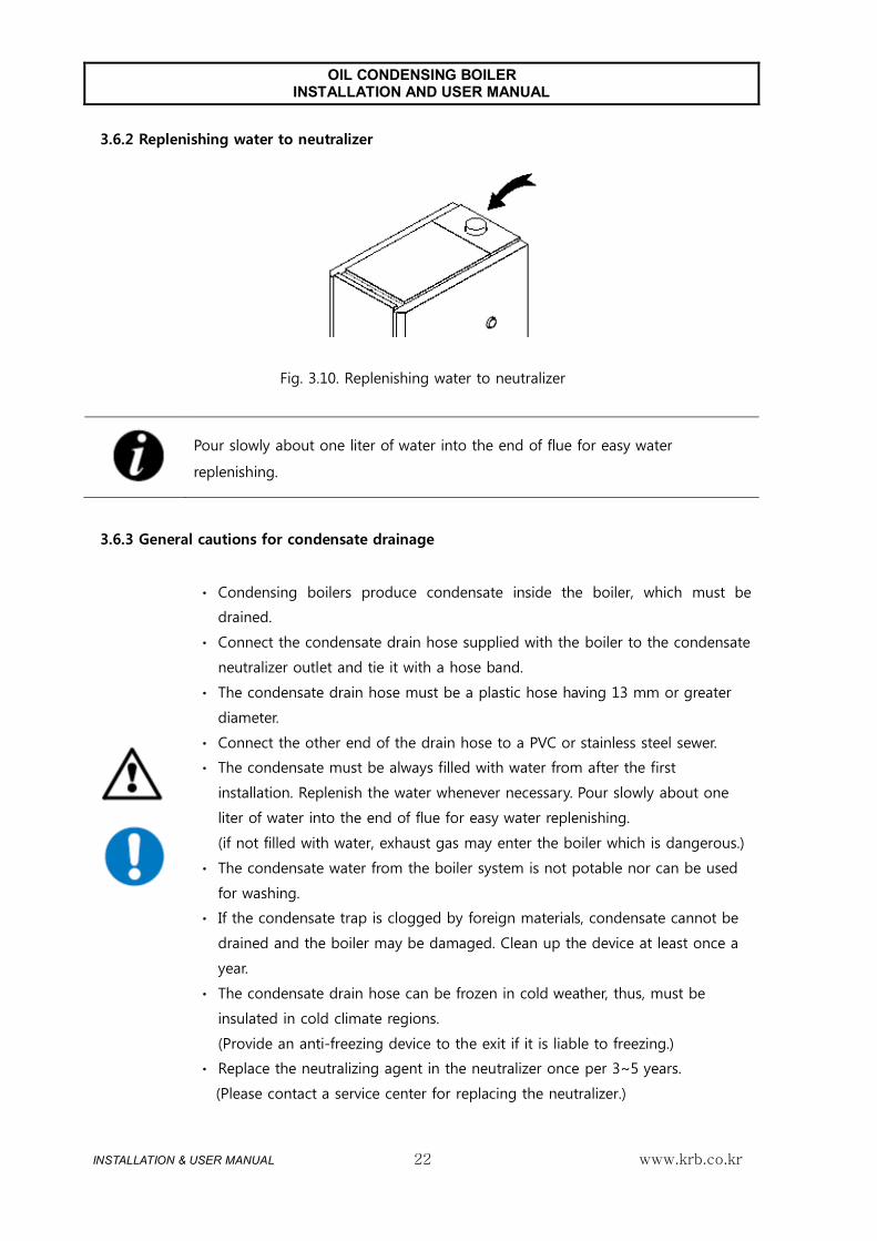
3.6.2 Replenishing water to neutralizer
Fig. 3.10. Replenishing water to neutralizer
Pour slowly about one liter of water into the end of flue for easy water
replenishing.
3.6.3 General cautions for condensate drainage
ㆍ Condensing boilers produce condensate inside the boiler, which must be
drained.
ㆍ Connect the condensate drain hose supplied with the boiler to the condensate
neutralizer outlet and tie it with a hose band.
ㆍ The condensate drain hose must be a plastic hose having 13 mm or greater
diameter.
ㆍ Connect the other end of the drain hose to a PVC or stainless steel sewer.
ㆍ The condensate must be always filled with water from after the first
installation. Replenish the water whenever necessary. Pour slowly about one
liter of water into the end of flue for easy water replenishing.
(if not filled with water, exhaust gas may enter the boiler which is dangerous.)
ㆍ The condensate water from the boiler system is not potable nor can be used
for washing.
ㆍ If the condensate trap is clogged by foreign materials, condensate cannot be
drained and the boiler may be damaged. Clean up the device at least once a
year.
ㆍ The condensate drain hose can be frozen in cold weather, thus, must be
insulated in cold climate regions.
(Provide an anti-freezing device to the exit if it is liable to freezing.)
ㆍ Replace the neutralizing agent in the neutralizer once per 3~5 years.
(Please contact a service center for replacing the neutralizer.)

OIL CONDENSING BOILER INSTALLATION AND USER MANUAL
INSTALLATION & USER MANUAL www.krb.co.kr 23
3.7. Fuel line installation
3.7.1 Fuel tank installation
Fig. 3.11. Fuel tank installation
A Away from the boiler by 2 m or more D Fuel valve (a must item)
B Fuel tank E Fire wall
C Fuel line
ㆍ Use a certified fuel tank.
ㆍ Install the tank at a place well-ventilated and safe from direct sunlight and
rain.
ㆍ Keep a safety distance of about 2 m from the boiler, or construct a fire wall
between the boiler and fuel tank.
ㆍ The fuel tank must be provided with a pressure escape tube and drain valve
for safety.
ㆍ Fuel outlet must be provided with a fuel cut-off valve.
ㆍ Fix the fuel tank on the ground to prevent falling over, and horizontal on the
ground.
ㆍ Height of the fuel tank must be within 2 m above and below the level of the
burner. (If lower than the boiler, ignition may fail.)
ㆍ The fuel pipe must be exposed and fixed to the ground to prevent
displacement.
ㆍ The fuel pipe must be made of an anti-corrosive material.

OIL CONDENSING BOILER INSTALLATION AND USER MANUAL
INSTALLATION & USER MANUAL www.krb.co.kr 24
3.7.2 Oil filter and fuel line installation
Fig. 3.12. Oil filter installation
A Oil filter (supplied with the boiler)
B Fasten clockwise using an appropriate tool.
Fig. 3.13. Oil hose connection
C Oil hose (supplied with the boiler)
D Oil hose bushing (Supplied with the boiler)
E Fuel pipe
F Seal the joints to prevent leak

OIL CONDENSING BOILER INSTALLATION AND USER MANUAL
INSTALLATION & USER MANUAL www.krb.co.kr 25
3.7.3 Fuel line air venting
Fig. 3.14. Fuel line air venting
A Fuel filter air vent screw
B Fuel pump air vent bolt
1 Open the fuel line valve to feed fuel.
2 Loosen the screw on fuel filter cap counterclockwise to remove air in the line. Tighten the screw when the fuel
oil spills out.
(This is applicable only when the fuel tank is higher than the fuel filter unit.)
3 If the fuel tank is lower than the filter unit, air cannot be removed with this method. In such case, loosen the
air vent bolt on the fuel pump and turn on boiler power supply.
4 After about 6~7 seconds, the fuel pump discharges air with ticking sound. The LED lamp on the controller
flashes and the boiler stops.
5 Turn off and on the power supply to the controller. All the air has been removed and fuel will be fed smoothly.
Then, close the air vent bolt and press Restart button to ignite the burner.

OIL CONDENSING BOILER INSTALLATION AND USER MANUAL
INSTALLATION & USER MANUAL www.krb.co.kr 26
3.8. Electric wiring 3.8.1. 3.8.1 General cautions for electric wiring
ㆍ Check that the power supply is in accordance with the specification on the
name plate (AC230V/50Hz).
Incorrect supply voltage can cause fire.
ㆍ Use an independent power receptacle, safe from rain and moisture.
ㆍ Do not connect ground cable to a lightening arrestor or fuel pipe.
Otherwise, the product may fail or even exploded.
ㆍ Boilers must be grounded to prevent electric shock or other accident by
leakage current.
ㆍ For the 230V power supply, grounding and cable works, observe the
applicable laws and regulations.
ㆍ If the 230V power supply is obtained by individual voltage raise in a 110V
region, make sure to provide a ground connection.
In this case, the capacity of the voltage step up transformer must be at least
1kW.
ㆍ Power receptacle must be away from the boiler by at least 300 mm.
ㆍ The grounding point must be at 300 mm or deeper in the ground.
OIL CONDENSING BOILER INSTALLATION AND USER MANUAL
INSTALLATION & USER MANUAL www.krb.co.kr 27
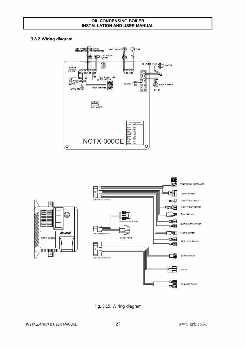
3.8.2 Wiring diagram
Fig. 3.15. Wiring diagram

OIL CONDENSING BOILER INSTALLATION AND USER MANUAL
INSTALLATION & USER MANUAL www.krb.co.kr 28
3.8.3 Connector cable structure
Fig. 3.16 16 Pin connector
Terminal No. Classification Color
1 - -
2 - -
3 AC 230V COM White
4 AC 230V Sky / Black
5 Burner motor Yellow
6 - -
7 Ignition transformer Red
8 Fuel pump Blue
9 Earth Yellow / Green
10 - -
11 - -
12 - -
13 Burner motor COM Yellow
14 - -
15 Ignition transformer COM Red
16 Fuel pump COM Blue

OIL CONDENSING BOILER INSTALLATION AND USER MANUAL
INSTALLATION & USER MANUAL www.krb.co.kr 29
Fig. 3.17. 14 Pin connector
Terminal No. Classification Color
1 Low water level sensor Red
2 DC 12V Red
3 GND Gray
4 GND Blue
5 GND White
6 GND Black
7 DC 12V Yellow
8 Low water level sensor COM Yellow/Green
9 Bimetal Thermostat Red
10 Temperature sensor Gray
11 Hot water sensor White
12 Room temperature controller Red
13 Flame detector Yellow
14 Air pressure switch Yellow

OIL CONDENSING BOILER INSTALLATION AND USER MANUAL
INSTALLATION & USER MANUAL www.krb.co.kr 30
Fig. 3.18. 8 Pin connector
Terminal No. Classification Color
1 Circulation pump Yellow
2 - -
3 3Way valve - Heating Red
4 3Way valve - Hot water Blue
5 Circulation pump COM Green
6 - -
7 3Way valve COM Black
8 - -

OIL CONDENSING BOILER INSTALLATION AND USER MANUAL
INSTALLATION & USER MANUAL www.krb.co.kr 31
3.9. Room temperature controller installation
1
Install the controller mounting plate in a place convenient
for operation, where the temperature varies by relatively
smaller, where there is no obstacle, at 1.2m ~ 1.5m above
the floor.
(Avoid the places close to frequently open/closed door, cold
draft, direct sunlight, within the reach of children.)
A Screws
B Hook
C Cable hole
2
Connect cable to the terminal block on the backside of the
room temperature controller.
3
Match the hook of the controller and the ring of the
mounting plate, pull down the controller while pressing
towards the wall.
• Do not lay under the floor, or in the same conduit with electric cable. Otherwise,
the signals may become instable which can cause boiler malfunction. In addition,
when the sheath of the cable is aged, the wires can cause short-circuit due to
leakage current or moisture.

OIL CONDENSING BOILER INSTALLATION AND USER MANUAL
INSTALLATION & USER MANUAL www.krb.co.kr 32
3.10. Checklist after installation
Is there any leak of water or fuel?
Is the boiler installed at the designated location and leveled?
Is there any inflammable material near the boiler?
Is the flue correctly installed?
Was the air in the fuel line removed?
Was the air in the hot water line removed?
Are the hot and low water lines separated?
Is the feed water line correctly installed?
Are the pipelines and flue properly insulated?
Is the power supply AC230V/50Hz?
Is the neutralizer filled up with water?
Is the fuel valve operation and no fuel leakage?
All above questions must be answered with YES to start up the boiler.

OIL CONDENSING BOILER INSTALLATION AND USER MANUAL
INSTALLATION & USER MANUAL www.krb.co.kr 33
3.11. Boiler commissioning
1
Connect power supply. (AC230V / 50Hz)
2 Open the fuel line valve to feed fuel.
(Vent the air in the fuel line first.)
3 Turn on power by pressing the power switch of the
controlled inside of the boiler.
And turn on the power button of the room
temperature controller.
If the boiler is not filled with water, Error 95 is
displayed.
4 Open the feed water valve to replenish water.
After water refill, 95 error is released.
Close the feed water valve when the pressure
1.5kgf/cm2.
(Feed water pressure must be lower than the max
allowable operation pressure.)
5 Set up the room temperature controller to a desired temperature. After temperature and reservation function setting, the operation lamp turns on or off, and the respective functions are executed. If ignition fails, press the power button on the room temperature controller for a restarting.

OIL CONDENSING BOILER INSTALLATION AND USER MANUAL
INSTALLATION & USER MANUAL www.krb.co.kr 34
4. Product Operation Method
4.1. Room Indoor temperature controller components
Fig. 4.1. Room temperature controller NCTR-50
1 Display Shows current/set-up
temperature, water
temperature, combustion status,
error code, and other
conditions of the boiler.
6 UP button Used to edit setting values.
2 Bath button Use this button to select
bathing function. 7 Down button Used to edit setting values.
3 Function button AT Home, Reservation, Outing
function selector button 8 Hot water
temperature
button
Use this button to set up
heating water temperature.
4 Room temperature
sensor Measures room temperature 9 Reservation setting
button Use this button for reserved
start up and shut down timer
setting. 5 LED indicator lamp Shows current function while
the boiler is in operation. 10 Power button Turns power ON/OFF. Use
this button to restart the
boiler after power-off or
troubleshooting.
1
5
6
7
8
10
9
2
3
4

OIL CONDENSING BOILER INSTALLATION AND USER MANUAL
INSTALLATION & USER MANUAL www.krb.co.kr 35
4.2 Heating function
4.2.1 Operation modes
1
With the room temperature controller power off, press
Heating/Water Temperature buttons simultaneously to
display modes.
2
Set up the desired operating mode using the UP (▲)/
Down (▼) buttons
Room Mode Water Temperature
Mode
3
After setting up a desired operating mode, press the
Function button to finish setting and return to the
previous function.
What is Operating Modes?
Heating mode can be classified into Room mode and Water Temperature mode
Room mode: the boiler operates by comparing the current temperature and set-
up temperature of the room temperature controller.
Water Temperature mode: the boiler operates by comparing the heating water
temperature of the room temperature controller and actual boiler water
temperature.
Press
imultaneously!

OIL CONDENSING BOILER INSTALLATION AND USER MANUAL
INSTALLATION & USER MANUAL www.krb.co.kr 36
4.2.2 Room mode operation
1
Set up the room temperature at desired level using the
UP (▲)/ Down (▼) buttons. (Temperature display
flashes.)
2
The desired room temperature can be set up between
10 ℃~45 ℃ at 1 ℃ unit.
3
After selecting the desired room temperature, the
setting will be entered and effective after about 10
seconds.
4.2.3 Water Temperature mode operation
1
Heating water temperature display will flash when the
heating water temperature setting key is pressed.
2
While the display is flashing, set up the heating water
temperature at desired level using the UP (▲)/ Down
(▼) buttons
3
The heating water temperature can be set up between
50 ℃~85 ℃ at 1 ℃ unit.
(Default setting: 80 ℃)
4
After selecting the desired room temperature, the
setting will be entered and effective after about 10
seconds.

OIL CONDENSING BOILER INSTALLATION AND USER MANUAL
INSTALLATION & USER MANUAL www.krb.co.kr 37
4.3 Reservation function
4.3.1 Execute reservation function
1
Select Reservation using the [At-Home, Reservation,
Outing] button. "Reservation” will appear in the
display.
(The operation lamp will be ON according to the
preset time, and Reserved run will be activated with
priority.)
▶Example: The boiler will run for 20 minutes, stop
for 2 hours, and run for 20 minutes, and so on.
4.3.2 Setting up timer function (min)
1 Select the Reservation function.
Set up the desired operating time (min) using the
UP (▲)/ Down (▼) buttons
When the setting is finished at this step, the
reserved stop time will apply first.
2 To change reserved stop time, press the
Reservation Setting button once again.
With the Up (▲)/ Down (▼) buttons, you can
adjust the time (minutes), when the Reserved Stop
time flashes.
When the setting is finished at this step, the
reserved stop time will apply first.
3 To change reserved starting time, press the
Reservation Setting button once again.
Using the Reservation function
By setting-up reserved operation appropriately to run the boiler for the desired
time, fuel cost can be saved. (You can set up reserved run and stop time
according to the season and the thermal insulation condition of the house.)
Press
Reservation
Setting
button and
set up
reservation
time
schedule

OIL CONDENSING BOILER INSTALLATION AND USER MANUAL
INSTALLATION & USER MANUAL www.krb.co.kr 38
4.4 Outing function
4.4.1 Enable leave function
1
Select Outing using the [At-Home, Reservation,
Outing] button. "Outing” will appear in the display.
(The Outing function maintains room temperature
at minimum level for freeze protection of the boiler
system.)
2
Press the power button, the boiler will be shut
down.
What is anti-freezing function?
Anti-freezing (freeze protection) function maintains the boiler system, floor
heating pipeline, and connecting lines at appropriate temperature to prevent
damage by freezing.
When you leave home in winter, the power of the boiler system must be ON and
the fuel supply valve must be open for freeze protection.
In extremely cold weather, set the room temperature at about 10~15 ℃ to
prevent freezing in a long leave.
▶ In the situation which falls under anyone below, the freeze protection function
does not work.
• Power failure or boiler power cord is unplugged
• Fuel supply valve is closed, or fuel supply is cut off.
• Water feed pipe or other exposed pipe is not properly heat insulated

OIL CONDENSING BOILER INSTALLATION AND USER MANUAL
INSTALLATION & USER MANUAL www.krb.co.kr 39
4.5 Bathing function
4.5.1 Execute bathing function
1 To use a large volume of hot water, select the Bath mode.
2 After 2 hours and 30 minutes after Bath setting, the setting will be reset and the system will return to the previous function.
4.5.2 Setting up bath water temperature
1 Press Bath button to enter Bath mode.
2 In this mode, press the Bath button for 5 sec. The display will flash as shown in the figure.
3 Bath water temperature can be set up between 41 ℃~85 ℃, at 1 ℃ unit
4 The setting will be entered and effective after about 10 seconds, if without any button input.
5 After setting, press the Function or Bath button to complete the setting and enter the respective function or Bath function.
• Take care of burn injury when using hot water.
• When using hot water, very hot water may come out of the hot water faucet.
Take special care for children and senior people.
• The water from the boiler system is not potable.
• After a long time of using hot water in heating mode, the water temperature
may be reduced.
• If the power turns Off and On in bath mode, the system will return to the mode
prior to bath.

OIL CONDENSING BOILER INSTALLATION AND USER MANUAL
INSTALLATION & USER MANUAL www.krb.co.kr 40
5. Product Maintenance
5.1. Boiler cleaning
1
Turn boiler power off and wait until the system is
cooled down sufficiently.
Close the fuel supply valve to cut off fuel feed.
Remove the A/S cover and front casing.
2
First, disconnect all the cables from the burner.
1. Disconnect copper fuel pipe from the burner
nozzle adapter using a tool.
2. Remove two fixing nuts on both sides of the
burner.
3. Remove 6 nuts on the hood and heat exchanger.
3
Disconnect the hose from the neutralizer at the
bottom of the boiler.
The hose is joined with a clip.
4
Remove the exhaust hood and the baffle plates in
the fire (smoke) tubes.

OIL CONDENSING BOILER INSTALLATION AND USER MANUAL
INSTALLATION & USER MANUAL www.krb.co.kr 41
5
Clean the fire tubes in the boiler using the brush
supplied with the boiler, by reciprocating 4~5 times
up and down.
6
The soot and other contaminants in the fire tube fall
down on the bottom. Pour wash water into the flue
tube to wash the soot away.
Connect an extra hose to the condensate pan at the
bottom of the boiler to help drain the wash water.
7
After cleaning, assemble the boiler in the reverse
direction of disassembly.
8
Verify that the boiler is assembled correctly.
ㆍ Soot or foreign matter in the boiler can reduce life span and efficiency of the
boiler, and can cause fire.
ㆍ Contact a nearby service center for cleaning by at least once a year.
ㆍ Cut off power supply before cleaning the boiler. Otherwise, the user may get
electric shock.
ㆍ Cool down the boiler sufficiently before cleaning the boiler. Failure to comply
with this can lead to burn of the user.
ㆍ Run the boiler from time to time in the rainy seasons to remove moisture
which can cause corrosion.
ㆍ Learn and understand the boiler structure before cleaning the boiler.

OIL CONDENSING BOILER INSTALLATION AND USER MANUAL
INSTALLATION & USER MANUAL www.krb.co.kr 42
5.2 Burner cleaning
1
Remove the burner and carry it to a bright place.
2
Wipe off soot, if any, from the burner tube with clean
cloth.
3
Remove the flame detector by rotating it in
counterclockwise. Wipe off soot, if any, from the
detector with clean cloth.
4
After cleaning, assemble the boiler in the reverse
direction of disassembly.
ㆍ Soot or other foreign matter on the burner tube and/or flame detector may
lead to boiler failure.
ㆍ Contact a nearby service center for cleaning by at least once a year.
ㆍ Cut off power supply before cleaning the boiler. Otherwise, the user may get
electric shock.
ㆍ Cool down the boiler sufficiently before cleaning the boiler. Failure to comply
with this can lead to burn of the user.
ㆍ Take care not to allow soot or foreign matter enter the burner during
cleaning.
ㆍ Do not attempt to disassemble or adjust other parts of the burner.

OIL CONDENSING BOILER INSTALLATION AND USER MANUAL
INSTALLATION & USER MANUAL www.krb.co.kr 43
5.3 Cleaning neutralizer
1
Turn off boiler power supply and remove front casing.
2
Remove all the screw bolts on top of the neutralizer
and remove the cap.
3
Remove foreign matter, if any, in the neutralizer.
Replace the neutralizing agent at every 3~5 years.
4
After cleaning, assemble the boiler in the reverse
direction of disassembly.
Refill the neutralizer with water.
ㆍ Cool down the boiler sufficiently before cleaning the boiler.
ㆍ Contact a nearby service center for cleaning by at least once a year.
ㆍ Wear safety gloves when handling the neutralizing agent or condensate, and
wash hands clean after handling.
OIL CONDENSING BOILER INSTALLATION AND USER MANUAL
INSTALLATION & USER MANUAL www.krb.co.kr 44
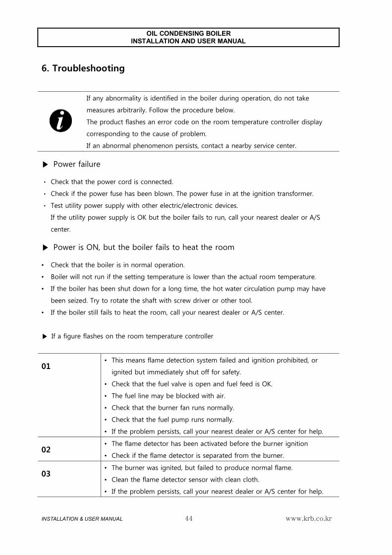
6. Troubleshooting
If any abnormality is identified in the boiler during operation, do not take
measures arbitrarily. Follow the procedure below.
The product flashes an error code on the room temperature controller display
corresponding to the cause of problem.
If an abnormal phenomenon persists, contact a nearby service center.
▶ Power failure
ㆍ Check that the power cord is connected.
ㆍ Check if the power fuse has been blown. The power fuse in at the ignition transformer.
ㆍ Test utility power supply with other electric/electronic devices.
If the utility power supply is OK but the boiler fails to run, call your nearest dealer or A/S
center.
▶ Power is ON, but the boiler fails to heat the room
• Check that the boiler is in normal operation.
• Boiler will not run if the setting temperature is lower than the actual room temperature.
• If the boiler has been shut down for a long time, the hot water circulation pump may have
been seized. Try to rotate the shaft with screw driver or other tool.
• If the boiler still fails to heat the room, call your nearest dealer or A/S center.
▶ If a figure flashes on the room temperature controller
01 • This means flame detection system failed and ignition prohibited, or
ignited but immediately shut off for safety.
• Check that the fuel valve is open and fuel feed is OK.
• The fuel line may be blocked with air.
• Check that the burner fan runs normally.
• Check that the fuel pump runs normally.
• If the problem persists, call your nearest dealer or A/S center for help.
02 • The flame detector has been activated before the burner ignition
• Check if the flame detector is separated from the burner.
03 • The burner was ignited, but failed to produce normal flame.
• Clean the flame detector sensor with clean cloth.
• If the problem persists, call your nearest dealer or A/S center for help.

OIL CONDENSING BOILER INSTALLATION AND USER MANUAL
INSTALLATION & USER MANUAL www.krb.co.kr 45
04 • The boiler water temperature sensor has failed, including open cable.
• Shut down the boiler, and call your nearest dealer or A/S center for help.
06 • APS Limit Switch open
• Shut down the boiler, and call your nearest dealer or A/S center for help.
07 • APS Limit Switch short.
• Shut down the boiler, and call your nearest dealer or A/S center for help
08 • The room temperature controller wire is too long (10m or longer), or it is
contacted with high voltage line or telephone line.
• Take care that cable cover is not damaged. Do not lay the wire together
with AC 230V cable or in an underground cable conduit.
• For a special case, reinstall with special cable
95 • This error code appears when the water level in the boiler is lower than
the low limit.
• Replenish water using the feed water valve, as necessary.
• If water replenishment fails to solve the problem, check the connection of
the low water level sensor and casing ground cable.
• If the problem persists, call your nearest dealer or A/S center for help.
98 • When overheat bimetal switch is disconnected
• If the problem persists, call your nearest dealer or A/S center for help.
99 • The heating water was overheated and the boiler was shut down
automatically for safety.
• The heating water circulation pump will start up and lower the water
temperature.
• If the problem persists, call your nearest dealer or A/S center for help.
Product Disposal
Observe the following regulations for product disposal.
• Shut down the boiler.
• Disconnect all the utility lines from the product.
• The product must be disposed of a qualified person.
• Follow the rules and regulations of the pertinent nation or region.
The waste from the product can be classified and recycled.

OIL CONDENSING BOILER INSTALLATION AND USER MANUAL
INSTALLATION & USER MANUAL www.krb.co.kr 46
8 Technical data
8.1. Basic specification
Item Unit TURBO
CONDENSING-13
TURBO
CONDENSING-17
TURBO
CONDENSING-21
Thermal
output
Condensing kW(kcal/h) 15.1 (13,000) 19.8 (17,000) 24.4 (21,000)
Normal kW(kcal/h) 14.4 (12,400) 18.6 (16,000) 22.7 (19,500)
Hot water output kW(kcal/h) 13.9 (12,000) 18.6 (16,000) 22.7 (19,500)
Fuel consumption Liter/h 1.44~1.76 1.89~2.29 2.32~2.83
Maximum heat input kW 15.58 20.97 26.36
Type
- - Floor installation, semi-closed, forced exhaust
ON/OFF
Modulating
multi stage
- On/Off
Fuel - Light Oil
Heat transfer area M2 1.26 1.26 1.43
Water volume Liter 28 28 24.2
Heating
efficiency
Condensing % 100 99 98
Normal % 94 93 92
Hot water efficiency % 94 93 92
Hot water heating type - Indirect heating
Hot water
supply capacity
ΔT=25℃ Liter/min 8.3 10.7 13.0
ΔT=40℃ Liter/min 5.2 6.7 8.1
Max. pressure for heating Bar 2.5
Max. pressure for hot water Bar 17.1
Pipeline
diameter
Heating A 25
Hot Water A 15
Flue Φ 77
Drain A 25
Dimension W * L * H 385 X 654 X 933
Product weight Kg 55 55 56
Power supply - AC 230V / 50Hz

OIL CONDENSING BOILER INSTALLATION AND USER MANUAL
INSTALLATION & USER MANUAL www.krb.co.kr 47
Power Consumption W 104 104 104
Standby power W 5 5 5
Standby loss W 0.111 0.111 0.111
Range of temperature control °C 45~85
Max Temperature range °C 85
Gas volume of the boiler ㎥ 0.00846 0.00846 0.00846
The required draught mbar 0.1 0.1 0.1
Gas side resistance and combustion chamber pressure
for boilers operating with positive pressure
mbar 0.2 0.2 0.2
Water resistance mbar 10K : 380 / 20K : 480
8.2. Combustion specifications
Item Unit TURBO
CONDENSING-13
TURBO
CONDENSING-17
TURBO
CONDENSING-21
Thermal output (condensing) kW 13.6~16.6 17.8~21.7 21.9~26.8
Thermal output (Normal) kW 12.9~15.8 16.7~20.4 20.4~24.9
CO emission rating Class 1 1 1
NOx emission rating Class 1 1 1
Smoke level No. 0 0 0
Exhaust gas temperature (Normal / Condensing) °C 85/60 90/65 95 / 70
Exit flue gas mass flow kg/s 0.0069 0.0093 0.0117

OIL CONDENSING BOILER INSTALLATION AND USER MANUAL
INSTALLATION & USER MANUAL www.krb.co.kr 48
8.3. Major components of the product
Item TURBO CONDENSING-13 TURBO CONDENSING-17 TURBO CONDENSING-21
Controller NCTX-300CE
Indoor temperature controller NCTR-50
Burner motor KM-061-E (1.5㎌)
Oil nozzle Danfoss 0.4×80˚H Danfoss 0.5×80˚H Danfoss 0.6×80˚H
Fuel pump K-TAISAN
MP35SLR-S E.P 0.5G * 8.5K
K-TAISAN MP35SLR-S
E.P 0.5G * 10K
Flame detector RS-500
Temperature sensor SD-450
Low level sensor WL-100
Ignition transformer EI-2P-C30
Inner circulation pump
GRUNDFOS UPM3 FLEX AS 15-70 130 AZJ

OIL CONDENSING BOILER INSTALLATION AND USER MANUAL
INSTALLATION & USER MANUAL www.krb.co.kr 49
8.4. Standard resistance of temperature sensors
The actual water temperature and the water temperature display on the room
temperature controller can be compared by measuring the resistance of the water
temperature sensor.

OIL CONDENSING BOILER INSTALLATION AND USER MANUAL
INSTALLATION & USER MANUAL www.krb.co.kr 50
8.5 Time chart
Fig. 8.1. Time chart for initial operation
Fig. 8.2. Time chart in loss of flame during operation
Burner motor
Ignition Trans.
Fuel pump
Flame detectort
Time (s)
6s 7s 7s
Burner motor
Ignition trans.
Fuel pmp
Flame detector
시간(초) 11s 1s 6s 7s 7s

OIL CONDENSING BOILER INSTALLATION AND USER MANUAL
INSTALLATION & USER MANUAL www.krb.co.kr 51
PRE PURGE TIME 6 ±1 s Time for purging waste gas in the combustion chamber until ignition transformer is activated, for safey
PRE IGNITION TIME 7 ±1 s Time interval for ignition transdormer to operate before fuel injection to help ignition
POST IGNITION TIME 7 ±1 s
Time interval for ignition transformer to operate after ignition to prevent ignition falire caused by incomplete combustion and ensure stable combustion
POST PURGE TIME 11 ±1 s Time for purging waste gas in the combustion chamber after burner off, for safety
BURNER SHUTDOWN TIME
1 s Time from loss of flame to reignition

OIL CONDENSING BOILER INSTALLATION AND USER MANUAL
INSTALLATION & USER MANUAL www.krb.co.kr 52
8.6 Burner fan motor performance curve
Fig. 8.3. Burner motor performance curve

OIL CONDENSING BOILER INSTALLATION AND USER MANUAL
INSTALLATION & USER MANUAL www.krb.co.kr 53
www.krb.co.kr
▶ The content of this manual may be subject to correction without prior notice for purposes of
improving the appearance and capabilities of the product.
▶ This company shall not assume responsibility for any accident caused by the user’s arbitrary
modification of the product.