tunnels and underground stations technical...
TRANSCRIPT

TUNNELS AND UNDERGROUND STATIONS
TECHNICAL MEMORANDUM
PRODUCT 9.9 Final
111111111111111111111111
HONOLULU HIGH-CAPACITY TRANSIT CORRIDOR ALTERNATIVES ANALYSIS/ DRAFT ENVIRONMENTAL IMPACT STATEMENT
prepared for:
City and County of Honolulu Federal Transit Administration
prepared by:
M: Parsons Brinckerhoff Quade & Douglas, Inc.
14 May 2007
AR00065304
Tunnels and Underground Stations Technical Memorandum
Honolulu High-Capacity Transit Corridor Project
May 14, 2007
Prepared for: City and County of Honolulu
and Federal Transit Administration
Prepared by: Parsons Brinckerhoff
AR00065305

Table of Contents Section Page
CHAPTER 1 INTRODUCTION 1-1
Alternatives Considered 1-1
Tunnels Considered 1-1
CHAPTER 2 UNDERGROUND STRUCTURES 2-1
Types of Underground Structures 2-1 U-Wall Sections 2-1 Guideway Tunnels 2-2 Underground Stations 2-3
General Assumptions for Layout 2-4 Tunnel Size 2-4 Tunnel Depth 2-5 Tunnel Ventilation 2-5 Underground Station Size 2-5
Tunnel Layout Geometry Guidelines 2-5 Tunnel Curvature 2-6 Grade 2-6 Portals 2-6 Side-by-Side Tunnel Separation 2-6 Over/Under Tunnel Separation 2-6
CHAPTER 3 GEOLOGICAL CONDITIONS 3-1
Geology of 0`ahu and Honolulu 3-1
Subsurface Geology 3-2
Hydrogeology 34
Geologic Tunneling Constraints 3-4
CHAPTER 4 CONSTRUCTION METHODS 4-1
Guideway Construction 4-1 Cut and Cover 4-2 Bored Tunnel 4-2
Station Construction 4-5 Cut and Cover (Bottom Up) 4-8 Cover and Cut (Top Down) 4-9 Conventional Mining 4-9
Instrumentation and Monitoring 4-9
CHAPTER 5 SELECTED UNDERGROUND STRUCTURES AND COST ESTIMATE 5-1
Selected Underground Structures 5-1 Hotel Street/Kawaiahaco Street Tunnel and Station 5-1 All Other Tunnels and Stations 5-1
Tunnels and Underground Stations Technical Report Page i Honolulu High-Capacity Transit Corridor Project
AR00065306

Table of Contents (Continued) Section Page
Cost Estimate 5-2
REFERENCES R-1
APPENDIX A CONCEPTUAL PLAN AND PROFILE DRAWINGS OF TUNNEL ALIGNMENTS UNDER CONSIDERATION A-1
APPENDIX B DETAILS OF TUNNEL BORING MACHINE TYPES AVAILABLE B-1
APPENDIX C COST ESTIMATE DETAILS C-1
List of Tables Table 1-1: Tunnels Considered 1-3
Table 2-1: Guideway Tunnel Layouts Overview 2-2
Table 2-2: Station Layouts Overview 2-4
Table 4-1: Summary of Guideway Construction Methods 4-1
Table 4-2: Retaining Wall Stiffness 4-6
Table 4-3: Retaining Wall Types 4-6
Table 4-4: Summary of Station Construction Methods 4-8
Table 5-1: Summary of Alignment Construction Methods and Cost Estimates 5-3
List of Figures Figure 2-1: U-Wall Section 2-1
Figure 4-1: Station Excavation and Construction Method using Cut and Cover (Bottom Up) 4-11
Figure 4-2: Station Excavation and Construction Method using Cover and Cut (Top Down) 4-12
Page ii Tunnels and Underground Stations Technical Report Honolulu High-Capacity Transit Corridor Project
AR00065307

Acronyms Used in this Document AA Alternatives Analysis
CSC Composite Section Costs
CTM Conventional Tunneling Method
DBEDT Department of Business, Economic Development and Tourism
DP Development Plan
DT S Department of Transportation Services
EPBM Earth Pressure Balance Tunnel Boring Machine
F TA Federal Transit Administration
HHCTCP Honolulu High-Capacity Transit Corridor Project
ID Inside diameter
LPA Locally-Preferred Alternative
NATM New Austrian Tunneling Method
OD Outside diameter
OMPO 0' ahu Metropolitan Planning Organization
ORTP 0 ahu Regional Transportation Plan
PR Puerto Rico
SEM Sequential Excavation Method
SFM Slurry Face Tunnel Boring Machine
TBM Tunnel Boring Machine
TSM Transportation System Management
UH University of Hawai`i
Tunnels and Underground Stations Technical Report Page iii Honolulu High-Capacity Transit Corridor Project
AR00065308

Chapter 1 Introduction This report documents the design of tunnels under consideration as part of the Honolulu High-Capacity Transit Corridor Project (HHCTCP). Chapter 1 includes a description of the area where the four tunnels under investigation are located. Chapter 2 describes the variety of underground structures being considered for this project, and the assumptions used to design the underground structures for this project. Chapter 3 summarizes the geotechnical condition along the tunnel alignments being considered. Chapter 4 presents possible construction methods to build underground guideway and stations. Included are recent mining technologies that significantly enhanced tunnel techniques and reduced construction costs. Chapter 5 summarizes the cost estimate to build the underground facilities being considered for this project.
Alternatives Considered
Four alternatives were evaluated in the Alternatives Analysis (AA) report. They were developed through a screening process that considered alternatives identified through previous transit studies, a field review of the study corridor, an analysis of current housing and employment data for the corridor, a literature review of technology modes, work completed by the 0' ahu Metropolitan Planning Organization (OMPO) for its Draft 2030 Regional Transportation Plan, and public and agency comments received during a formal project scoping process held in accordance with requirements of the National Environmental Policy Act (NEPA) and the Hawai`i EIS Law (Chapter 343, Hawai`i Revised Statutes). The four alternatives are described in detail in the Honolulu High-Capacity Transit Corridor Project Alternatives Analysis Definition of Alternatives Report (DTS, 2006a). The alternatives evaluated in the AA report are as follows:
• No Build Alternative
• Transportation System Management Alternative
• Managed Lane Alternative
• Fixed Guideway Alternative
In December 2006 Honolulu's City Council selected the Fixed Guideway Alternative as the Locally-Preferred Alternative (LPA). The alignment selected as the LPA does not include any tunnels.
Tunnels Considered
Of the various alignment segments investigated in the AA, as part of the Fixed Guideway Alternative, four included tunnels. These tunnel alignments are located in the Chinatown and Capitol Special Design Districts that have cultural, historical, and environmentally sensitive areas. Tunnels were considered because they would have less long-term environmental impacts and/or better transit operations, as compared to an elevated or an at-grade fixed guideway. The four tunnels are shown in Figure 1-1 and include the following:
Tunneling and Underground Stations Technical Report Page 1-1 Honolulu High-Capacity Transit Corridor Project
AR00065309
• Beretania Street Tunnel
• Waimanu Street Tunnel
• Kawaiaha`o Street Tunnel
• King Street Tunnel.
It should be noted that the LPA selected by City Council is an elevated Fixed Guideway that follows Nimitz Highway and Halekauwila Street, makai of Chinatown and Downtown; and thereby does not include any of the tunnels. The LPA alignment follows the same alignment that was selected for the Honolulu Rapid Transit Program in 1992.
Beretania Street Tunnel: This alignment is located on the mauka side of Chinatown and Downtown and is located under Beretania Street that has a 5 to 6 traffic lane cross section. Placing the guideway underground minimized the impact to adjacent culturally-significant buildings: Saint Andrews Cathedral, Washington Place, and the State Capital. Length is 5,128 feet or 6,395 feet depending on whether it connects to North King Street or Dillingham Boulevard. On the 'Ewa side, the tunnel has a portal in the Kukui Gardens parking area for the North King Street connection and on properties makai of Ka`aahi Street for the Dillingham Boulevard connection. On the Koko Head side, the portal is located in the City Municipal Building parking structure. There is one underground station at Fort Street Mall to serve the area along the North King Street connection alignment; and a second underground station makai of 'A' ala Park for the Dillingham Boulevard connection.
Waimanu Street Tunnel: This tunnel, and the Kawaiaha`o Street Tunnel, connect to an at-grade fixed guideway on Hotel Street that goes through the central portions of Chinatown and Downtown. They descend into tunnel to minimize impacts to `Iolani Palace, the State Capitol, and Honolulu Hale. The Waimanu Street Tunnel is 3,840 feet long and has one underground station located next to the City's Municipal Building. The 'Ewa portal is located on Hotel Street just 'Ewa of Richards Street. The Koko Head portal is located on properties makai of Kapi` olani Boulevard and Koko Head of Dreier Street.
Kawaiaha`o Street Tunnel: This tunnel is similar to the Waimanu Street tunnel, but is shorter (3,000 feet long). The Koko Head side portal is located on Kawaiaha`o Street on the Koko Head side of South Street. One underground station at Punchbowl Street would serve the area.
King Street Tunnel: The alignment for this tunnel goes through the central portions of Chinatown and Downtown. The tunnel is located under King Street, which in Chinatown has a 4-lane traffic cross section. The underground alignment minimizes impacts to Chinatown, lolani Palace, King Kamehameha statue, and Honolulu Hale. Of the four tunnels, this is the longest (6,233 feet or 7,003 feet depending on whether it connects to North King Street or Dillingham Boulevard). The 'Ewa side portal location for the Dillingham Boulevard connection is similar to the Beretania Street Tunnel and for the North King Street connection is on properties on the 'Ewa side of Iwilei Road. The Koko Head portal is the same as for the Waimanu Street tunnel. There are 3 underground
Page 1-2 Tunneling and Underground Stations Technical Report Honolulu High-Capacity Transit Corridor Project
AR00065310

stations on the Dillingham Boulevard connection alignment: Ka' aahi Street, Fort Street Mall, and Punchbowl Street. The Ka' aahi Station is an elevated station on the 'Ewa side of Liliha Street for the North King Street connection.
During the Honolulu Rapid Transit Program a tunnel alignment under Hotel Street was also considered and compared to a King Street Tunnel alignment. The King Street Tunnel was determined to be a better option because 1) the tunneling environment was found to be superior, 2) the station configurations were more patron friendly, and 3) costs were less. For the HECTC's AA, a Hotel Street Tunnel option was not considered. The King Street Tunnel was the same as the previous study, except for an alignment modification on the 'Ewa side of Nu'uanu Stream, where a new high-rise building has been constructed.
Table 1-1 includes a summary of the tunnel characteristics.
Table 1-1: Tunnels Considered
Tunnel Name 'Ewa Tunnel
Portal Koko Head
Tunnel Portal
Approximate Tunnel Length
Underground Stations
Beretania Street Tunnel (on Beretania Street/ South King Street alignment)
From North King: Kukui Gardens parking lot From Dillingham: makai side of Ka`aahi Street
Makai side of Beretania Street through portions of the City's Municipal parking structure
1.2 miles • Ka`aahi — from
Dillingham only
• Beretania/Fort
Hotel Street/ Waimanu Street Tunnel (on Hotel Street/ Waimanu Street/ Kapi`olani Boulevard alignment)
Hotel Street between Alakea and Richards Streets
Makai side of Kapi`olani Boulevard at current BMW dealership
0.7 mile • King/Kaprolani
Hotel Street/ Kawaiaha`o Street Tunnel (on Hotel Street/ Kawaiaha`o Street/ Kapi`olani Boulevard alignment)
Hotel Street Between Alakea and Richards Streets
Kawaiaha`o Street between South and Curtis Streets
0.6 mile • State Capitol
King Street Tunnel (on King Street/ Waimanu Street/ Kapi`olani Boulevard alignment)
From North King: Lot at Iwilei Road and Nimitz Highway From Dillingham: Ka`aahi Street
Makai side of Kapi`olani Boulevard at current BMW dealership
1.5 miles
• Ka`aahi — from Dillingham only
• King/Fort Street Mall
• King/Punchbowl
The conceptual plan and profile drawing illustrating the alignment of these tunnels and the stations along them are provided in Appendix A.
Tunneling and Underground Stations Technical Report
Page 1-3 Honolulu High-Capacity Transit Corridor Project
AR00065311

Chapter 2 Underground Structures
Types of Underground Structures
"Underground structures" refers categorically to all transit facilities that will be below ground surface when construction is complete. Three types of underground structures are described in this report: U-Wall sections, guideway tunnels (including tunnel portal), and stations.
Underground utilities for water, sewer, electric power, communications, and the like that either serve the transit system, or have to be relocated or otherwise accommodated to build the underground transit structures are not described in this report.
Construction methods for the underground structures are discussed in Chapter 4.
U-Wall Sections
The portion of the guideway that descends from ground level to the tunnel portal constitutes the U-Wall section. The U-Wall structure, or an open-topped box, is required as a transition from the at-grade or aerial transit line to the underground part of the alignment. These structures have the appearance of a pair of retaining walls. For various practical structural and water-tightness reasons, the walls and bottom are typically one structure, thus termed a "U-Wall."
This transition structure is formed by a ramp in an open cut section as shown in Figure 2-1. The vertical portions of the U-Wall retain the ground material on the sides of the guideway. Beyond the tunnel portal, shown in the back of the U-Wall section in Figure 2-1), the guideway is completely enclosed in a tunnel section.
Figure 2-1: U-Wall Section
Tunneling and Underground Stations Technical Report
Page 2-1 Honolulu High-Capacity Transit Corridor Project
AR00065312

Guideway Tunnels
The configurations of tunnel sections vary depending on the type of guideway that is enclosed. Transit study terminology uses the term "dual guideway," which is generic for having two tracks ("guideway") for trains operating in opposing directions on individual dedicated tracks. The "dual" term distinguishes the layout from other configurations such as with a single line having operation in both directions, and split configurations where the guideways have different alignments, for instance along different city streets.
Dual guideways can be installed in either a pair of parallel tunnels, with both tunnels being large enough for a single track, or a single tunnel large enough for both tracks.
All guideway tunnels being considered for this project have a dual guideway configuration. A dual guideway can be either horizontal (side by side) or vertical (one on top of the other) depending on the right-of-way available and other constraints. Table 2-1 provides an overview of the guideway layouts.
Table 2-1: Guideway Tunnel Layouts Overview
Guideway Type Typical Uses Advantages Disadvantages
Dual Guideway, two side by side tunnels
• Standard application for most situations.
• Required for center platform stations unless a separate transition structure is constructed.
• Least tunnel depth.
• Separate tunnels provide emergency egress during emergencies.
• Fire/life safety considerations may require separate tunnels.
• Requires two tunneling operations.
Dual Guideway, singe tunnel
• Can be used where right of way is limited,
• Side platform stations to accommodate minimum center-to-center track spacing.
• Requires only one tunneling operation.
• Larger tunnel must be deeper to maintain required cover.
• Fire/life safety considerations may require divider wall to provide egress during emergencies, particularly involving fire.
Dual Guideway, two vertically stacked tunnels
• Used where right of way is limited,
• Usually considered only after traditional side-by- side configurations are not workable.
• Rarely, if ever, first choice for tunnel layout
• Fits in least possible right of way.
• Typically requires 3-level station.
• Requires two tunneling operations.
• Constructability and sequence of construction, especially in poor tunneling conditions, have to be considered in more detail.
Single Guideway, split configurations
• Generally only used where underground structures prohibit one of the dual guideway alternatives,
• Fits in small right of way.
• Single tunnel has more latitude for vertical and horizontal curves.
• Requires separate stations for inbound and outbound lines.
• At transfer points requires elaborate station design.
Page 2-2
Tunneling and Underground Stations Technical Report Honolulu High-Capacity Transit Corridor Project
AR00065313

Underground Stations
Station type (center or side platform), entrances, space for fare collection and patron cueing, escalators, stairways, elevators, and platforms for both inbound and outbound trains would be determined in preliminary design and were not considered in detail in this study. All underground stations would have these public areas but would also have non-public areas for mechanical/electrical physical plant, drainage, and maintenance.
From the transit operations perspective, center and side platform stations have different traffic (user/patron) circulation patterns and are laid out to fit site-specific need and practicality of transit station entrances.
Center Platform stations are usually adopted to provide the most patron-friendly options from either inbound or outbound trains to most or all station entrances. Twin single-track tunnels with a suitable separation are the simplest form of tunnel construction to connect to a center platform station. A reduction in passenger circulation space and escalator equipment can be achieved with this type of station. Station overall widths are also slightly smaller for center platform stations.
Side platform stations are usually adopted where a single large-diameter bored tunnel with twin tracks or a cut and cover box connects to the station. A transition structure is not needed to widen the track spacing that is otherwise required to accommodate a center platform. Side platform station types are also located in the vicinity of ramps or at the ends of the alignment where track switching using crossovers is required. With minimum center to center track spacing, the length of switches and cross-over is minimized.
Stacked stations with platform levels above one another for each track can also be adopted where the right of way is restricted. However, ease of passenger circulation is reduced with added disadvantages of an increase in depth needed for the tunnels, track separation, and the impact on the alignment configuration on each side of the station.
Stations are also typically described by the number of levels. Typically the first level is the ticketing concourse with lower levels being platforms and/or plant facilities. Table 2-2 presents the variety of station layout options and their typical uses, general advantages, and general disadvantages.
Tunneling and Underground Stations Technical Report Page 2-3 Honolulu High-Capacity Transit Corridor Project
AR00065314

Table 2-2: Station Layouts Overview
Station Type Typical Uses Advantages Disadvantages
Center Platform
• VVhere the guideway is in twin single track tunnels.
• Travel demand and usage is high
• Overall width is less than side platform.
• Requires less passenger circulation space and escalator equipment.
• If dual guideway is in single tunnel, requires transition structures.
Side Platform • Where the guideway is in a single large diameter bored tunnel with twin tracks.
• Where the guideway is installed using a cut and cover technique.
• In the vicinity of ramps or where track switching using crossovers is required.
• Simple construction. • Station is slightly wider than center platform type.
• More escalator equipment is required.
Stacked Platform
• Where right-of-way is limited,
• Overall width is minimized,
• Passenger circulation is not optimal.
• Deep station excavation in poor ground conditions has constructability issues.
2-Level • Initial systems without interchanges.
• Shallow station.
• Relatively least cost.
• Better passenger circulation.
• Longer because plant equipment placed at either or both ends of station.
3-Level • Deeper stations (required by clearances, tunnel form, or interchange layouts).
• Interchange Stations.
• Stations can be shorter because plant equipment can be placed vertically.
• Slower passenger circulation due to depth.
• More expensive.
General Assumptions for Layout
Tunnel Size
Precedent light rail systems with tunnels were reviewed (San Francisco Muni Central Subway, Tren Urbano (San Juan, PR), and Los Angeles Eastside Extension). At this stage of project development, a tunnel size was selected to be sufficiently large to accommodate the size likely to be needed when a rail system technology is selected. Light rail is a commonly used technology and typically requires the largest tunnel size. Based on precedent, an 18 foot 10 inch internal diameter (ID) tunnel was selected. Assuming a 10-inch-thick segmental precast concrete one-pass tunnel lining is used, the outside diameter (OD) would be 20 feet 6 inches.
Page 2-4 Tunneling and Underground Stations Technical Report Honolulu High-Capacity Transit Corridor Project
AR00065315

Tunnel Depth
Existing structures, geologic conditions, and the overall track profile (vertical alignment) as the transit line goes from either at-grade or aerial structure to tunnel are all factors that are used to determine tunnel depth. In establishing a minimum tunnel depth, a key dimension is the distance from the top of rail to the finished ground surface. Definition of this clearance is important to establishing where the finished tunnel portals will be in relation to the tunnels running under cross streets or other surface features.
Where the tunnel can be built by cut and cover, the least depth is desirable and typically less costly. Avoidance of existing utilities, especially sewers and other drainage structures, usually requires greater tunnel depth. The other major factor in setting tunnel depth is getting the tunnel deep enough to match the depth required at underground stations, particularly where a mezzanine is desired for patron circulation. A mezzanine greatly increases flexibly of use by patrons but typically requires a deeper station and connecting tunnels.
Geologic conditions will often control tunnel depth. In general better rock or soil conditions are better for tunneling. The ideal condition is to set tunnel depth in the most favorable tunneling ground conditions. Geologic conditions and tunneling method control what is practical to construct at least cost and risk.
Apart from all considerations for tunnel depth indicated above, some minimal depth of tunnel is desirable. After the start of tunneling at a portal, a minimum thickness of ground above the tunnel excavation of 1.5 times the tunnel diameter (1.5 OD) was established.
Tunnel Ventilation
Fire/life safety considerations will establish requirements for mechanical ventilation of all underground structures. Later in design, ventilation schemes will need to be established in order to define where mechanical rooms will be needed. Once the basic plan and profile of each alternative is established, ventilation schemes can be established. At this level of study (alternatives analysis), requirements for ventilation typically do not drive definition of an alternative.
Underground Station Size
At this time, underground station configurations are only generally known. Platform length has been set at 280 feet, and nominal total underground station box length of 300 feet was used for layout purposes.
Tunnel Layout Geometry Guidelines Based on precedent from past and on-going transit projects, the following guidelines were used in the layout of the tunnels.
Tunneling and Underground Stations Technical Report Page 2-5 Honolulu High-Capacity Transit Corridor Project
AR00065316

Tunnel Curvature
The minimum turning radius for tunnel alignment to be constructed using a pressurized face tunnel boring machine (TBM) was set at 450 feet. In very specific situations that site conditions impose, a lesser value may be feasible when special accommodations are made in the design of a TBM. In the case of the Waimanu Tunnel, which has a 400 feet radius curve, the length of tunneling on the curve is short (distance less than 150 feet) and is acceptable. For non-TBM-excavated tunnels, there is typically no limit on how tight a curve can be, and practical transit operations alignment standards would apply.
Grade
Grades are generally set by transit operations considerations, not by tunneling considerations. Grades of up to 6 percent are feasible for rail-operations in a TBM-excavated tunnel; in general, the project guideline is to keep grades less than 3 percent once the track has made the transition from surface or elevated to underground.
Portals
The physical "portal" for the start of tunneling is usually not the same as finished tunnel portal that the public will see. This situation exists where the transit line goes from aerial, or at grade, into a portal approach U-wall section and then to the finished tunnel portal and start of the tunnel. As an example, see the 'Ewa portal for the Waimanu Tunnel on Figure TWAI-1 in Appendix A. The permanent 'portal" is at Sta 1380+20, but the portal for the start of tunneling that was used in the cost estimates is 1383+50. For the final portal, the distance from ground surface to crown (top) of the tunnel can be minimal. It can be on the order of a few feet, but usually is greater to give more distance above the structure to accommodate utilities and landscaping.
Side-by-Side Tunnel Separation
Preferred typical spacing for extended lengths: 2.0 OD center-to-center.
Preferred minimum spacing: 1.5 OD but can be reduced to 1.25 OD center-to-center for transition segments and special situations.
This project is known to have very limited right of way in the downtown Honolulu area with many constraints existing in the form of historic fences, structures, and the like. With the use of ground improvement to stabilize the pillar between adjacent tunnels, clear distances between the extrados of tunnel linings can be less than what results with the 1.25 OD spacing, which gives about a 5-ft-wide pillar. Ground improvement may consist of mechanical reinforcement, grouting, or other appropriate means.
Over/Under Tunnel Separation
Minimum center-to-center spacing in vertical dimension or radial separation distance for transitions from side-by-side to over/under configuration was set at 1.5 OD. An absolute minimum vertical separation is 1.25 OD center-to-center. At this time, there are no situations where this guideline would be applicable.
Page 2-6 Tunneling and Underground Stations Technical Report Honolulu High-Capacity Transit Corridor Project
AR00065317

Chapter 3 Geological Conditions Geologic conditions are complex along the alignments being considered. Although no new subsurface investigation was undertaken for this study, there is a fair amount of subsurface information available from previous work along similar alignments. Additional understanding of the subsurface has come from the experience of deep building excavations in the downtown Honolulu area. This study has made use of this information to characterize tunnel ground conditions.
Specific subsurface investigations were preformed for transit tunnels during prior transit studies, including: Hotel Street (ICF Kaiser, 1991) and King Street (ICF Kaiser 1992). Where the old and current alignments are the same or in close proximity, specific geologic information is available. For a new tunnel alignment (B eretania Street/King Street), definition of the geologic conditions was based on an understanding of the geologic setting, and extrapolation where thought to be reasonable from the existing borings done for the prior transit studies.
The previous geotechnical studies were considered a conceptual level study. Regardless of which tunnel may be selected, a more detailed geotechnical engineering investigation would need to be performed to provide site-specific information for design, cost estimation, and construction planning.
Geology of 0`ahu and Honolulu The Island of 0`ahu is comprised of two volcanoes: the Koolau Volcano and the Wai` anae Volcano. The Wai` anae Range is the older of the two volcanoes and lies to the west of the younger Koolau Volcano.
The Wai` anae Volcano is a shield volcano built up by a series of eruptions, which produced the Wai`anae Volcanic Series. The Wai` anae Mountains, the eroded remains of the Wai`anae Volcanic Shield, comprise western 0' ahu.
The Koolau Volcano is an unusually elongate shield volcano built principally by eruptions along a northwest-southeast trending rift zone. The lavas produced during the shield-building phase of the volcano are known as the Koolau Volcanic Series and consist of series of lava flows and ash that can range in thickness from less that 1 foot to several feet. The Koolau Mountains, the eroded remains of the Koolau Volcanic Shield, are approximately 37 miles long, trending northwest-southeast, and comprise approximately two-thirds of 0' ahu (Macdonald et al, 1983).
A long period of volcanic quiescence followed the Koolau shield-building stage, during which erosion occurred and alluvium and marine sediments accumulated along coastal regions. Deep valleys were incised into the bedrock by major streams and subsequently filled with sediments.
Following a long period of volcanic quiescence, volcanic activity resumed. These subsequent eruptions formed cinder cones, such as Diamond Head, and constitute the
Tunneling and Underground Stations Technical Report Page 3-1 Honolulu High-Capacity Transit Corridor Project
AR00065318

Honolulu Volcanic Series. Lavas of the Honolulu Volcanic Series include basalt and ash (Macdonald et al, 1983).
Subsurface Geology In 1992 12 exploratory borings were drilled along the King Street tunnel alignment, ten in-hole permeability (falling head) tests were performed, and five piezometers were installed. A number of soil borings were also drilled along the Hotel Street tunnel alignment during previous studies. The borings penetrated to a depth of approximately 100 feet below ground surface. The soil and rock encountered in those borings was grouped into the following nine main stratagraphic units:
1. Basaltic Lava Flows. Typically dense to very dense, hard, highly to slightly fractured, fresh to moderately weathered, vesicular basalt. Lava flows encountered in this study probably belong to the Honolulu Volcanic Series.
2. Alluvial Deposits. Primarily saturated soft to stiff silts and clays and very loose to dense silty sand and gravel. Cemented nodules and basalt boulders are present and should be expected in tunneling through these deposits.
3. Organic Deposits. Primarily saturated very soft to medium stiff, highly compressible peat, organic silty sand and sandy silt containing organic fibers and decayed wood fragments. Near Nu'uanu Stream these organic deposits may also contain flood deposited pebbles, gravel, and boulders.
4. Lagoonal Deposits. Consists predominantly of very soft to medium stiff highly compressible sandy and gravelly silt and clay, and very loose to loose silty sand.
5. Reef Deposits. Three types of reef deposits were encountered in the exploratory borings.
a. Coral (Type I). Formed in-place, hard, slightly weathered to unweathered, coral reef.
b. Coral (Type II). Reworked and recemented coral fragments.
c. Coralline Sand and Gravel. Generally consists of locally cemented to uncemented calcareous sand (a weak sandstone-like material) and cemented to uncemented coralline gravel, sometimes in a clayey to silty matrix.
6. Beach Deposit. Primarily loose to medium dense silty fine sand and poorly graded sand, usually interbedded or associated with reef deposits. Some of the beach deposits are cemented and others contain gravel.
7. Volcanic Cinders. Consists primarily of poorly graded sand-sized material and silty sand. In some areas, particularly where the deposit is relatively thick, such as within the infilled channel under Kapi`olani Boulevard, they appear to be fused or cemented.
8. Volcanic Tuff. Typically exhibited as a rock that, as a result of high during volcanic activity, consists of fused volcanic rock particles, closely to moderately
Page 3-2 Tunneling and Underground Stations Technical Report Honolulu High-Capacity Transit Corridor Project
AR00065319

fractured, thinly bedded, but may contains cobble and boulder-sized material also deposit during explosive volcanic activity.
9. Fill (man-made). Generally consists of silty sand and gravel. The gravel component is predominately composed of coral or basalt. The fill may contain cobbles, boulders, other debris and obstructions.
All of these deposits are considered part of the caprock on the coastal plane of 0' ahu. The fill material was generally located near the surface, but the other deposits were found at a wide variety of depths along the tunnel alignments. Results of the geotechnical exploration indicate that world-wide fluctuations in sea level from approximately 640,000 years ago to present resulted in migrating shorelines and depositions of a wide range of alluvial deposits and marine sediments at various times. The sea level changes also caused periodic erosion of those deposits, creating channels that where later filled in by lava flows, reef deposits, and other alluvial or marine deposits as sea levels continued to change. These factors resulted in the wide variety of relatively thin, horizontally-discontinuous deposits encountered in the borings.
The geology encountered can be most easily described by breaking the tunnel alignments into segments. As in indicator or tunneling conditions, the upper approximately 50 feet of the material encountered in each segment is briefly described below.
• 'Ewa end (`A`ala Park) to Maunakea Street (Chinatown). This area contains a major erosional feature that was infilled by organic and lagoonal deposits. Tunnels would be constructed mainly in very soft to soft, highly compressible organic deposits.
• Maunakea Street to Bethel Street (Chinatown). This segment is dominated by a range of reef deposits overlying alluvial deposits, including beach deposits. Tunneling would be in weak rock and mixed-face conditions.
• Bethel Street (Chinatown) to Punchbowl Street (Capital District). Reef deposits are predominate in this section with the alluvial deposits at deeper depths than the previous section. Tunneling would be in weak rock and mixed face conditions.
• Punchbowl Street (Capital District) to Koko Head end (Kalia`ako). An erosional feature infilled by alluvial deposits and volcanic cinders was encountered in this section. Tunneling would be in alluvium, mixed face and weak rock, but the in-filled section would be tunneling in saturated, flowing ground conditions in the cinders.
During previous studies no borings were advanced along the Beretania Street tunnel alignment. Due to its slightly more mauka position it would be expected that fewer lagoonal and coral deposits would be present and more alluvial and volcanic deposits would be present.
Tunneling and Underground Stations Technical Report Page 3-3 Honolulu High-Capacity Transit Corridor Project
AR00065320

Hydrogeology The groundwater elevation observed during previous studies generally indicated the groundwater elevation is generally within a few of sea level throughout the study area. Ground surface elevations range from approximately 5 to 25 feet above sea level, with the more mauka Beretania Street being higher than Hotel Street and King Street. Groundwater elevation was observed to fluctuate with ocean tides. For all planning purposes, all tunneling work can be considered to be below the water table.
Geologic Tunneling Constraints Geologic conditions are the major factor influencing the method of tunnel construction and strongly affect the final design characteristics of the permanent structures. Based on the results of the previous studies the following factors may constrain the construction method and underground structures:
• Groundwater is shallow and most underground construction will take place below the groundwater table in saturated conditions.
• Geologic conditions are comprised of materials considered to be relatively soft, with the exception of basalt (see following regarding basalt), which in construction terms would be "soft-ground" tunneling.
• Basalt, which is extraordinarily hard, would require "hard rock" tunneling methods to excavate, such as by blasting. When tunneling encounters both soft ground and hard rock, a "mixed face" condition exists. If the basalt can be avoided then mixed faced tunneling involving hard rock would be circumvented. It appear possible that the basalt could be avoided in the more makai tunnels but the more mauka Beretania Street tunnel is more likely to encountered the basalt. The level of geotechnical investigation completed thus far is insufficient to establish if basalt can be avoided.
• Other "mixed face" tunneling conditions may be encountered given the interbedded nature and the wide variation in strength or behavior between the relative soft geologic strata, for example cemented coral deposits and potentially flowing beach sand deposits.
• Construction in lagoonal soil deposits, which are very soft, will probably require ground improvement techniques, regardless of the selected tunnel construction method.
• Ground and structure settlement during construction will be an issue throughout the tunnel alignments due to the shallow groundwater and fine-grained nature of many of the soil deposits.
• In open cuts, excavation by blasting or by mechanical methods, such as hoe ram equipment, may be required to excavate through the coral reef deposits.
Page 3-4 Tunneling and Underground Stations Technical Report Honolulu High-Capacity Transit Corridor Project
AR00065321

Chapter 4 Construction Methods For some transit structure types, more than one construction method may be applicable. Construction method is important since community and environmental impacts vary considerably between the alternative methods. At one extreme is true tunneling (completely below the ground surface); at the other extreme is cut and cover construction that starts with a deep excavation in which the concrete structures are built, the remaining excavation is then backfilled, and the ground surface (street or other) is finally restored.
This report presents the range of construction methods. Although the emphasis is on the application of tunneling, which typically has the least public impact during construction, the full range of underground structure construction methods was considered. Feasibility with current tunnel construction technology and best available technology are addressed. Cost and risk in general are considered in a qualitative sense.
Guideway Construction Constructing the tunnel guideway could be performed using a variety of methods, including:
• Cut and Cover
• Bored Tunnels
- Tunnel Boring Machines (TBMs)
- Conventional Tunneling
These methods are discussed in the following sections and summarized in Table 4-1.
Table 4-1: Summary of Guideway Construction Methods
Alternative Primary Uses Advantages Disadvantages Cut and • Shallow guideway. • Generally simpler • Significant interference Cover • Transitions to at-grade or working conditions due to with subsurface utilities.
elevated guideway. access from surface. • Requires extensive temporary or permanent utility relocation.
• Significant disruptions to at-grade facilities such as roads.
Bored • Deep guideway. • Less environmental • Typically more costly. Tunnels in • Where there is a need to impact than other • Difficult access due to General avoid disruption to major methods. single point of access
city streets, buildings, or • Less utility relocation and length/depth of utilities, required compared to cut
and cover. tunnel.
Tunneling and Underground Stations Technical Report
Page 4-1 Honolulu High-Capacity Transit Corridor Project
AR00065322

Alternative Primary Uses Advantages Disadvantages TBMs • Long runs of deep • Possible to construct • Tunnel geometry is
guideway. water-tight tunnel in one pass.
restricted to the circular shape.
• Dewatering not required where pressurized-face TBMs are used.
• Tunnel curvature is limited by ability of TBM being used.
• Generally faster than conventional tunneling once underway.
Conventional • Short runs of deep • Tunnel geometry can be • Requires dewatering in Tunneling guideway. customized to the project. saturated conditions.
• Transitions from • Faster mobilization for • Higher risk of tunneling guideway to stations or construction compared to problems in unstable other structures. TBM. ground, such as
• VVhere ground conditions • No limits on tunnel grade running/flowing sands.
preclude the use of TBMs (hard rock or extreme mixed face).
or curvature. • Requires the removal of a greater volume of material than TBMs.
Cut and Cover
Cut and cover tunnel construction is a traditional method used for over 100 years for underground transit construction. Cut and cover construction is typically employed where guideway is shallow and in the transitions where the guideway rises to ground level and connects to an at-grade or aerial structure. In these transitions the cover to the ground surface reduces, and a cut and cover box is commonly used until the roof slab rises to ground level. Thereafter, the transition structure is formed by a ramp in an open cut section (U-wall).
Construction of cut and cover guideway under city streets involves complex site arrangements to facilitate traffic movements around the work site and usually involves extensive utility diversions prior to commencement of construction. Major utility diversions can take up to two to three years and must be considered as long lead time work on the project critical path before cut and cover construction can commence. Where utilities cannot be diverted, they must span the excavation and are at risk of damage during the excavation and concreting period. In addition, for larger utilities it is not possible to provide excavation support in advance and complex support systems involving highly engineered ground improvement techniques, such as grouting, are sometimes necessary.
Bored Tunnel
Tunnel construction can be accomplished using either Tunnel Boring Machines (TBM) or conventional methods. Either TBM or conventional tunneling is preferable to cut and cover where there is a compelling need to avoid disruption to major city streets, to avoid the environmental impact of open excavations, or to go under existing structures.
Page 4-2 Tunneling and Underground Stations Technical Report Honolulu High-Capacity Transit Corridor Project
AR00065323
Tunnel Boring Machines
In the previous studies of transit in Honolulu (ICF Kaiser, 1991 and 1992), tunneling methods as practiced at that time were considered. For many tunnel projects, the long-established, older tunneling techniques for difficult geologic conditions had questionable applicability because of being too costly or considered to be technically not feasible to construct. Tunneling under compressed air is an example. In the years since those studies, approximately 15 years, there has been substantial, positive change. As elaborated below, methods and equipment that were emerging for use in the early 1990's have been improved to become often a method of choice for tunneling on many difficult tunneling projects. What was previously difficult to construct can now be done with less risk and greater assurance of success.
Tunneling equipment technology changes have generally made tunneling more cost-competitive. The major improvements have come with less risk of tunneling problems, improved quality of tunnel lining with regard to water tightness, and greater assurance that the tunneling project will be completed successfully. The tunneling equipment on its own will not be sufficient to ensure success. Achieving success in construction will also require a program of risk management, and construction contract terms that deal with projects risks in the context of a tunnel construction projects including the selection of competent contractors that bring experienced management and labor to the project.
A variety of soft ground tunneling equipment, which are generically termed "tunnel boring machines" (TBM), are in use to varying degrees around the world at this time. They include:
• Free Air Tunnel Shield
• Compressed Air Tunnel Shield (limited)
• Pressurized/Closed-Face
- Earth Pressure Balance Machine (EPBM)
- Slurry Face Machine (SFM)
These TBMs are described in more detail in Appendix B.
The tunnel lining, which is installed as TBM excavation takes place, can also vary. Most commonly the lining material is segmental precast concrete that is assembled to form a ring. Segments and each successive ring of segments are bolted together. Special gaskets made from neoprene or other elastic material placed between all segment joints creates a watertight tunnel lining. When precast tunnel lining with gaskets is installed behind a TBM, this is referred to as a "one-pass" lining. A secondary lining after tunnel excavation is not needed. More details of lining of the tunnel are also described in Appendix B.
The use of pressurized/closed-face TBMs and one-pass precast concrete tunnel lining has become routine globally, as well as in the United States. With the present understanding of site conditions, closed-face TBMs would be required on this project in order to successfully tunnel through the varied soft-ground conditions below the groundwater
Tunneling and Underground Stations Technical Report Page 4-3 Honolulu High-Capacity Transit Corridor Project
AR00065324

table. Using TBMs of this type, the dual guideway can be twin single-track tunnels with 2 tunnels each about 20.5 feet in diameter, or one larger tunnel (well over 30 feet diameter) for both tracks. Even with TBM-excavated tunnels, some tunnel excavation by conventional means is typically required for transition and special structures.
Examples of recent and relevant projects that employed the pressurized-face tunneling construction method include:
• Los Angeles MTA, Eastside Extension. Two EPBMs were used that installed one-pass precast segmental concrete tunnel lining to construct light rail transit tunnels. The tunnel was designed for earthquake conditions.
• Portland, Oregon Westside and Eastside Combined Sewage Overflow (C SO) Projects. Slurry-face type pressurized-face EPBMs were used for the Westside project for long tunnels well over 10,000 ft in length with diameters approximately 15 feet. For the in-progress Eastside project, a 25-foot-diameter slurry TBM is being used. Tunnel ground conditions consist of an ancient river deposit of cobbles and gravel under or next to the Willamette River.
• Port of Miami Tunnel. Although construction has not started on this project, design/build procurements are in progress that require the use of either an EPBM or a slurry shield TBM to provide the required tunnel face stability for a pair of 45-foot diameter tunnels. Tunnel face conditions are geologically similar to those in Honolulu with marine deposits of interbedded soil and coral below sea level.
Conventional Tunneling
Excavation by mining rather than the use of TBMs has varying terminology. For the purposes of this report, the following are not different "methods" but different names and acronyms that have resulted from global tunnel practices:
• Conventional Tunneling Method (CTM)
• Sequential Excavation Method (SEM)
• New Austrian Tunneling Method (NATM)
Using conventional tunnel construction methods, the geometry of the tunnel can be customized to the needs of the project and be designed for twin or single tracks. Even with TBM-excavated tunnels, some tunnel excavation by conventional means is typically required for transition and special structures.
These conventional tunneling methods are nowadays commonly used for transitions, short lengths of tunnel where the use of TBMs would be uneconomic, and for ground conditions unsuitable to TBMs. These methods also use mechanical excavation methods such as road headers, impact breakers (hoe-ram), and the like. The specific equipment used for excavation is dependent on ground conditions, in particular rock hardness, groundwater conditions, and permeability.
In Honolulu conventional tunneling using road-headers or manual mining will require, for the mainline tunnels, the use of SEM or the NATM. Each method relies on,
Page 4-4 Tunneling and Underground Stations Technical Report Honolulu High-Capacity Transit Corridor Project
AR00065325

depending on ground conditions, minimizing the volume of tunnel excavation that can be physically excavated and gradually enlarging by mining heading and bench or by mining for larger tunnels in a sequential process at multiple headings. It is anticipated that conventional tunneling will be required primarily for cross passage construction or for starter tunnels for TBM assembly and start of tunnel driving from a shaft.
In the process of conventional tunneling, an initial tunnel lining must be placed as the headings (a specific portion of the full face of tunnel being advanced) are excavated, or mined forward in limited lengths. By the use of shotcrete with mesh or fiber reinforcement, and possibly steel dowel ground reinforcement, an initial tunnel lining is established. This initial lining can be strengthened, if necessary, by the use of lattice girders or steel arch rib supports that are shotcreted into the tunnel lining. After tunnel excavation is complete, it is most often necessary and desirable to install a waterproof membrane on the shotcrete initial lining followed by the final cast-in-place concrete lining. The labor input is greater and the rate of excavation with conventional (sequential excavation) tunneling is significantly slower than a one-pass lining erected using a TBM. Therefore, it is economically advantageous to undertake long tunnel drives, the majority of tunneling, wherever possible, using TBMs. However, TBMs cannot tunnel everything, and some conventional tunnel is usually needed.
Station Construction From the construction perspective, constructability of any underground station becomes a matter of depth and width of excavation, and the impact of construction on the community. Three principal approaches to underground station construction are as follows:
• Cut and cover (bottom up)
• Cover and cut (top down)
• Conventional mining
Unlike the pure transit guideway tunnel segments, the stations typically have irregular shapes. They are an underground building that requires retaining walls in addition to floors and columns like that of a building. Special design and constructability conditions for underground transit stations must be addressed. An example is that deflection of the retaining walls must be considered as part of the initial wall design. Historically-based values of building damage related to ground movement caused by wall deflections from past underground transit stations have resulted in requiring stronger or stiffer walls for purely constructability reasons, not for the final structural loading. Another special requirement is that a soil retaining structure must be adopted where groundwater levels are high to limit final leakage into the structure and, thereby, reduce consolidation settlement where compressible soils are present, which could damage buildings. To minimize settlement where close to buildings, a stiffer structure is commonly adopted. The varying level of stiffness of cut and cover, cover and cut, and open cut construction are shown in Table 4-2.
Tunneling and Underground Stations Technical Report Page 4-5 Honolulu High-Capacity Transit Corridor Project
AR00065326

Table 4-2: Retaining Wall Stiffness
Support Stiffness Description/examples High Cover and cut construction: temporary struts installed before permanent
works (floors or roof of transit station) are installed at high level.. Moderate Cut and cover construction: temporary struts or tie-backs installed before
permanent work (invert/bottom slab of transit station) are installed at low level.
Low Cantilever walls, (open cut): temporary struts of low stiffness or temporary props installed at low level.
Source: CIRIA C580, London 2003.
The types of retaining wall that can be used similarly reflect structure stiffness and water tightness and, generally in urban areas, slurry walls are used where deflections must be tightly controlled and where the risk of significant wall movement cannot be tolerated. Table 4-3 summarizes the types of retaining walls.
Table 4-3: Retaining Wall Types
Wall Type Advantages Limitations Steel Sheet piles
• Provides an economic finish for shallow walls.
• No excavation support to be removed,
• Suitable as a water-retaining wall.
• Can be used as both a temporary and permanent wall.
• Lower cost.
• Maximum pile length approximately 100 feet. Practical length substantially less in stratified with hard strata.
• Potential declutching in coarse
grained soils.
• Flexible wall with higher deflection.
Soldier pile and timber lagging
• Can be installed around obstructions such as utility crossings.
• Lower cost wall
• Not suitable for long term water retention.
• Cannot be used for excavation below groundwater in coarse grained soils.
Contiguous pile (Tangent Pile)
• The lowest cost form of concrete piled wall.
• Not a water retaining solution.
• Not a permanent solution in any soil due to gaps between piles, unless a structural facing is applied.
Secant piles • Possible to construct a permanent water retaining wall.
• The material for the primary female piles is either a standard concrete mix, retarded to reduce strength when the secondary piles are constructed or a reduced strength concrete mix.
• The depth is limited by verticality tolerances which may determine the extent of contact of the secant piles.
• Water tightness.
• More expensive wall.
Page 4-6
Tunneling and Underground Stations Technical Report Honolulu High-Capacity Transit Corridor Project
AR00065327

Wall Type Advantages Limitations Slurry Walls • A permanent water-retaining wall. • Horizontal continuity is difficult to (Cast-in-place • Can be installed to great depths, provided achieve between panels. concrete diaphragm
verticality tolerances can be accepted. • Cannot follow intricate plan outlines.
walls) • In some circumstances, the face of the • The i nstallation equipment is diaphragm wall can form the final finish extensive, requiring large site areas subject to surface cleaning and removal of protuberances.
for accommodation of the fluid plant, reinforcement cages and the
• Use of water stops in the wall joints excavation plant.
significantly reduces water paths through • Disposal of support fluid is costly and joints, dependent on fluid type.
• Most expensive wall due to mobilization costs.
Adapted from: CIRIA C580, London 2003
Varying solutions have been developed to expedite the construction of underground stations. Experience has shown that the use of large open site areas fully surrounding the station box, and unhindered by traffic maintenance requirements, permits fast wall installation, particularly using a sophisticated plant (excavation equipment and all related equipment to manage permanent materials and excavated material). Specifically engineered and purpose-built equipment has evolved to permit construction of station walls in difficult ground conditions, such as where hard strata are present. In difficult conditions with varying strata, rock, and boulders, a diaphragm wall can be constructed using a Hydrofraise, which is a drilling machine that has the cutter head or excavators powered by down-the-hole hydraulic motors. It is typically mounted on a crawler crane and uses a slurry system to remove cuttings from the excavation. Although more expensive to mobilize, such specialized equipment gives significant benefits in production rates for wall installation and thus reducing the time needed for site occupation. Ease of access to the site also permits use of multiple units of excavation equipment such as long neck excavators and can allow for alternative methods of concrete works such as precast beam installation for roof slabs or prefabricated reinforcement cages for lower slabs. In addition, construction allowing the use of tower cranes throughout the structural construction period greatly expedites the delivery of equipment and materials to all areas of the excavation. Wherever possible constraints on open excavation should be avoided.
The critical activities in the scheduled completion of an underground station include:
1. Completion of all above and below ground utility diversions including traffic equipment relocations and road signage
2. Completion of traffic diversions allowing work to start
3. Completion of diaphragm wall excavation and concreting
4. Completion of bulk excavation
5. Completion of tunnel breakouts
6. Tunnel connections
7. Completion of station base slab after tunnel connections
Tunneling and Underground Stations Technical Report Page 4-7 Honolulu High-Capacity Transit Corridor Project
AR00065328

8. Completion of remaining structural works
9. Flood-proofing and station cleaning
10. Track installation for equipment delivery
11. Works Train access
12. Escalator delivery
13. Electro mechanical systems and finishes installation
14. Local testing
15. Systemwide testing and test running
16. Trial running
17. Approval for service running
Of the above, items 1 and 2 require detailed interface with, and the approval of, external agencies. Successful coordination with these agencies is critical to a timely start of the works and subsequent compliance with the project schedule and budget. The remaining activities lie within the control of the owner except where these works result in an impact on adjacent residents and users. Typical influences on project progress include third party concerns such as safety, noise, vibration, night-time working particularly during concreting, dust, water discharge from excavation particularly during heavy rain, settlement and ground loss outside the site, and construction traffic. Public perception of each of these activities must be carefully managed in order to facilitate the required completion of the works within the site.
Table 4-4: Summary of Station Construction Methods
Alternative Primary Uses Advantages Disadvantages Cut and Cover • Shallow stations in open
areas. • Simple.
• Least Costly.
• Significant interference with subsurface utilities.
• Significant disruptions to at-grade facilities such as roads.
Cover and Cut • Shallow stations where impact to community is an issue.
• Reduces community impact relative to cut and cover.
• Significant interference with subsurface utilities.
Mining • Deep stations.
• Where there is a need to avoid disruption to major city streets, buildings, or utilities.
• Less environmental impact than other methods.
• More costly.
• In poor ground conditions the costs are considerably higher.
Cut and Cover (Bottom Up)
Cut and cover is the simplest and often least costly for shallower depths. The sequence of cut and cover construction is illustrated in Figure 4-1. Cut and cover, also known as "bottom up" construction has vastly different construction impacts compared to
Page 4-8
Tunneling and Underground Stations Technical Report Honolulu High-Capacity Transit Corridor Project
AR00065329

conventional mining and results in a tunnel box structure, and in the context of this report is considered a "tunnel", but construction is not considered "tunneling."
Cover and Cut (Top Down)
Cover and cut, also known as "top down", construction is an important variation from cut and cover (bottom up) construction in that it is intended to reduce community impact by reducing the time the street or other areas are completely committed to construction. The sequence of cover and cut construction is illustrated in Figure 4-2.
Conventional Mining
The principal advantage of a mined station is substantial reduction, to near elimination in some situations, of community impact by construction. Mined stations are typically more costly than cut and cover or cover and cut. Feasibility and cost of construction are controlled largely by geologic conditions. In competent rock, underground stations are readily excavated with conventional mining techniques. For poor ground conditions of weak or poor quality rock, or soil, cost is typically much greater. Where project conditions are compelling, underground transit stations in such conditions are feasible. An example is the Rio Piedras underground transit station in San Juan, Puerto Rico. No mined stations are being considered, but more technical details are presented later in this report.
Instrumentation and Monitoring For all forms of underground works, it is necessary to understand the ground response to underground excavation and, in urban areas, large numbers of arrays of instrumentation are necessary to continuously provide feedback on ground movements, deformation of the excavation support under load, and the impact of settlement on adjacent structures caused by excavation. Instrumentation can be monitored either remotely or by manual means. For instance, a field surveyor monitoring large numbers of instruments may not be able to collate the data and issue the information for review to the engineer until the end of the day or even the day after the readings. Therefore, if a problem arises and is not immediately identified, it may take 8-12 hours after readings have been taken to observe that alert levels have been exceeded. Therefore in inaccessible locations or for significant structures such as buildings, key roads, or utilities where information is required quickly, remote monitoring is usually prescribed. These instruments come with a higher capital cost but this can be offset when consideration of the labor required to undertake less frequent manual readings.
Tunneling and Underground Stations Technical Report Page 4-9 Honolulu High-Capacity Transit Corridor Project
AR00065330

BUILDINGS BUILDINGS
■UEN■ ■1--1■
i■■ I DIAPHRAGM WALL/ SECANT PLE
AUGERED OR
DRILLED PILES
DIAPHRAGM WALL/ SECANT PILE
FIRST ROAD OCCUPATION FENCE BUILDINGS BUILDINGS
SOLDIER P LEA
THIRD ROAD OCCUPATION
CONSTRUCT TEMPORARY TRAFRC DECKS
BUILDINGS FENCE BUILDINGS BUILDINGS FENCE
SIDE WALL
BASE SLAB CONCRETE
BUILDINGS
FIFTH ROAD OCCUPATION
FENCE
= =
1■■ 1■■ I
■ E -••i■ I■ Il
1=0.1 1■■ ■13
BUILDINGS FENCE BUILDINGS
SUPPLEMENTARY RESTRUTTING IF REQUIRED
BUILDINGS BUILDINGS
SIXTH & SEVENTH ROAD OCCUPATION FENCE
BUILDINGS BUILDINGS ■■■
•=i BUILDINGS FENCE
11
STAGE 1 STAGE 2 STAGED STAGE 4 STAGES
I. RELOCATE UTILMES/REMOVE SURFACE OBSTRUCTIONS, ROAD WIDENING, I. INSTALL ROAD DECK AND SUPPORTING STEEL BEAM GIRDERS. 1. INSTALL REMAINING TEMPORARY TRAFFIC DECK 1. EXCAVATE UNDERNEATH TEMPORARY DECKS. 1. WATERPROOF BASE. DIVERT TRAFFIC. 2. MATCH TOP OF DECK AND TOP OF CURB OR FOOTPATH. 2. TRAFFIC FLOWS ON TEMPORARY DECK 2. INSTALL STRUTS & BRACINOS AS EXCAVATION PROCEEDS. 2. CAST BABE SLAB.
2. CONSTRUCT DIAPHRAGM WALL FOR RETAINING WALL AROUND STATION PERIMETER. 3. TRAFFIC FLOWS ON TEMPORARY DECKS.
3. INSTALL AUGERED OR DRILLED PILES ALONG STATION (SPACING AS NEEDED).
STAGES
1. REMOVE SECOND TEMPORARY STRUT. 2. CAST SIDE WALLS AND CONCOURSE SLAB. 3. CAST ROOF BLAB.
STAGE?
T. REMOVE ALL TEMPORARY STRUTS/PILES.
STAGES
I. CUT OFF TEMPORARY PILES AND DIAPHRAGM WALLS AT ROOF SLAB. 2. BACKFILL AND COMPACT OVER ROOF SLAB SELECTED BACKFILL MATERIALS. 3. REMOVE TEMPORARY DECKS AND ROAD REINSTATED. 4. RETURN TRAFFIC TO NORMAL ROAD SURFACE.
STAGES
1. CUT OFF ALL TEMPORARY DRILLED PILES. 2. TOUCH UP AND WATERPROOF AND SEAL HOLES IN SLAB AS REQUIRED. 3. CONSTRUCT PLATFORM, STARS AND OTHER STRUCTURAL COMPONENTS.
Figure 4-1: Station Excavation and Construction Method using Cut and Cover (Bottom Up)
Tunneling and Underground Stations Technical Report
Page 4-11 Honolulu High-Capacity Transit Corridor Project
AR00065331

DiAPHR11,GM WALL/ -- SECANT PILE
DIAPHRAGM WALL/ SECANT PILE
BUILDINGS FIRST ROAD OCCUPATION FENCE
BUILDINGS BUILDINGS BUILDINGS
ACCESS FOR CONTINUED CONSTRUCTION
FINAL ROAD OCCUPATION
BUILDINGS
NO FILL
,
STATION ROOP SLAB —1/-
SECOND ROADWAY OCCUPATION
FENCE —%
THIRD ROAD OCCUPATION FENCE
BUILDINGS BUILDINGS
FENCE
E SLAB
FENCE BUILDINGS
MINM IPA
ROOF SLAB
CONCOURSE SLAB
BASE SLAB
BUILDINGS BUILDINGS BUILDINGS BUILDINGS
STAGE 1
1. RELOCATE UTILITIES/REMOVE SURFACE OBSTRUCTIONS, DIVERT TRAFFIC, CONSTRUCT FENCE.
2. CONSTRUCT DIAPHRAGM WALLISECANT PILES WHICH LATER BECOMES RETAINING WALL AROUND STATION PERIMETER.
STAGE 2
1. RE-OPEN CLOSED ROADWAY, SHIFT TRAFFIC. 2. EXCAVATE HALF WIDTH WITH TRAFFIC DIVERTED ONTO OTHER HALF.
CAST HALF TOP SLAB. 3. REMOVE DIAPHRAGM WALL ABOVE ROOF & WATERPROOF ROOF 4. CAST OR PLACE TEMPORARY RETAINING WALL.
STAGE 3 1. BACICFILL THE EXCAVATED HALF AND RESTORE ROAD ON THIS HALF. 2. EXCAVATE OTHER HALF ROOF SLAB 3. CAST OTHER HALF OF TOP SLAB. 4. REMOVE TOP OF DIAPHRAGM WALL & WATERPROOF ROOF SLAB.
STAGE 4
1. BACKFILL AND RESTORE ROAD TRAFFIC & UTILITIES. 2. PROVIDE SITE AREAS FOR SOIL REMOVAL & CONCRETE/ REINFORCEMENT
DELIVERIES THROUGH SLAB.
STAGES
I. EXCAVATE UNDERNEATH TOP SLAB. 2. INSTALL STRUT IF REQUIRED.
STAGES I. EXCAVATE BELOW CONCOURSE SLAB LEVEL, INSTALL STRUTS TO BASE SLAB LEVEL 2. CAST BASE SLAB AND COLUMNS. 3. REMOVE TEMPORARY STRUT ABOVE BASE SLAB.
STAGE? 1. CAST CONCOURSE SLAB. 2. REMOTE STRUTS. a CONSTRUCT PLATFORM. STAIRS AND OTHER STRUCTURAL COMPONENTS. 4. REINSTATE ROAD AND UTILITIES.
Figure 4-2: Station Excavation and Construction Method using Cover and Cut (Top Down)
Page 4-12
Tunneling and Underground Stations Technical Report Honolulu High-Capacity Transit Corridor Project
AR00065332

Chapter 5 Selected Underground Structures and Cost Estimate
The selected underground structures, the selected method of construction, and cost estimate for each tunnel alignment is summarized in Table 5-1.
Selected Underground Structures
Except for the Kawaiaha`o Street Tunnel, the design for the HHCTCP tunnels are based on TBM tunneling. The portals of all tunnels constructed using open cut U-wall construction. The plan and profile of the conceptual tunnel alignments is shown on the drawing in Appendix A. The drawings indicate which construction techniques would be used to build the tunnel.
Hotel Street/Kawaiaha`o Street Tunnel and Station
Because it is relatively short and the surface along its route is relatively open the Hotel Street/Kawaiaha`o Street tunnel could be built using the cut and cover technique rather than a TBM. Because the cut and cover technique would be used to install the dual guideway, the guideways would be adjacent to each other. The guideway tracks would be approximately 27 feet below the ground surface throughout the approximately 0.6 mile long tunnel.
Because the guideways would be adjacent to each other and not very deep, the King/Kapi` olani Station would be a side platform station. The station would not have a mezzanine and entrances for outbound and inbound platforms would be separate at ground level.
All Other Tunnels and Stations
All the other tunnels would be bored using an Earth Pressure Balance Machine (EPBM) TBM. TBM tunneling was selected for these longer tunnels over cut and cover in order to (a) limit environmental impacts, (b) limit disruption to street level activities, and (c) lower cost by avoiding utilities. The EPBM was selected due to its ability to tunnel through the saturated soft sediments and mixed-face conditions anticipated.
Two parallel bores with the inbound and outbound guideways side by side in separate tunnels. No over/under tunnels would be required. Outside diameter of the tunnel bores would be approximately 20.5 feet wide. Following the guideline of having approximately a ground cover of at least 1.5 times the tunnel diameter, the top (crown) of the tunnel would be at least 31 feet below ground level; therefore, the guideway track would be at least 46 feet below ground level. Due to ground surface elevation variation, the guideway track would reach depths of up to approximately 62 feet.
Although the bulk of the tunnels would be bored/mined using an EPBM, some other construction methods would be required near the portals. Both open cut (U-wall) and cut
Tunneling and Underground Stations Technical Report Page 5-1 Honolulu High-Capacity Transit Corridor Project
AR00065333
and cover construction methods would be used near the portals in order to obtain the depth where EPBM could take over.
With the guideway being at sufficient depth and the inbound and outbound in side by side tunnel configuration, the underground stations would be 2-level center platforms with the first level being a ticketing concourse and the second level being the platform level.
Cost Estimate Cost estimates were generated for each tunnel alignment and are summarized in Table 5-1. The cost estimate details are provided in Appendix C. The cost estimates presented in this report are strictly for the construction of the underground tunnel structure and do not include utility relocation costs, underground station costs, track work that would be installed in the tunnels, or transit system controls that would be installed in the tunnels (i.e. train control systems and ventilation). The cost estimates to relocate utilities and build the stations were presented in the Capital Costing Memorandum for the project. The cost estimates presented here do include labor and materials to excavate the tunnel and build the reinforced concrete tunnel structures, including walls, piles, tie-backs, and one-pass precast tunnel lining segments, among other structural items.
The cost estimate was generated by estimating the units of excavation and structure indicated to be required. A resource-based cost estimating approach was used, which is like that used by heavy construction tunnel contractors. Cost of labor and materials are used directly in this approach for the major cost item, tunneling. Labor rates appropriate for Hawai`i, work crew sizing, and productivity assumption were based on past experience performing similar tunnel projects. Costs were appropriately marked up to account for Hawai`i's construction materials plus the mobilization of required equipment to the islands.
Page 5-2 Tunneling and Underground Stations Technical Report Honolulu High-Capacity Transit Corridor Project
AR00065334

I Total T
unneling
C
SI) =
I Cu
t and Cover
Tota
l EP
BM
(two 20
.5' dia. b
ores)
Total E
PB
M S
ide by S
ide L
ength
E
PB
M S
ide b
y Side
EP
BM
Sid
e by S
ide
EP
BM
Sid
e by S
ide
I Cut and C
over
C
SI) =
IT
un
nel T
ype
I King/P
unchbow
l
I King/B
ethel
I Ka`aahi
IC
enter Platform
Statio
ns
I Total T
unneling
C
SI) =
I Cu
t and Cover
Tota
l EP
BM
(two 20
.5' dia. b
ores)
Total E
PB
M S
ide by S
ide L
ength
E
PB
M S
ide b
y Side
EP
BM
Sid
e by S
ide
I Cut and C
over
C
* SI) =
IT
un
nel T
ype
Tunnel M
ethod
X = • CO Cl) ,-1. CD CD ,-1. —I C = = CD
t 3 2 Z o m- X —. =
co
X M
CO Cl) ,-1. CD CD ,-1. —I C = = CD
t 3 2 CI —. = —. =
co m-sa 2
41.• _s. —s.
(.0 0
++
41.• c) CO
(.0 0
14
02
+2
1
13
26
+2
0
13
48
+5
0
13
45
+0
0
13
41
+0
0
1365+20 1
34
2+
25
C,) _s. co +
—s. 0
41.• _s. —s.
(.0 0
++
41.• cp CO
(.0 0
14
02
+2
1
13
15
+5
5
13
12
+0
5
13
08
+2
5
C.n (j) 111 a Pk '
14
15
+4
0
-1=• —s. —s. + (.0 0
-1=• 0 co + (.0 0
13
78
+8
9
13
51
+4
5
13
48
+5
0
13
45
+0
0
1368+20 1
34
5+
25
1
32
1+
10
14
15
+4
0
-1=• —s. —s. + (0 0
-1=• 0 co + (0 0
13
78
+8
9
13
15
+5
5
13
12
+0
5
m u z ri•
2.1 fa •
7,632 3
50
30
0
12,4
66
6,2
33
(3) 0) (0
5,2
69
I\3 (.0 0)
35
0
40
0
300 3
00
30
0
8,3
83
3
50
30
0
14,0
06
-,1 - 0 0 0.)
(3) a) co
6,3
34
3
50
38
0
(feet)
Leng
th
113,068
4,5
32
—s. 0
(.0 ---.1
-.4 CO
—s. ---.1
13,102
5,4
20
—s. —s. CO
0 -,1
4,5
32
_s. 0
CO CO
85,242
12,857
4,4
87
($ 000)
Tunnel
Construct
Cost E
stimate
152,641
159,310
-En 0 0 0
Tunnel C
onstruct C
ost w
ith 35%
C
ontractor
Mark
up
25.2
23.4
-En 0 0 0
Co
st per Foot
(included in
tunnel CS
C*)
AR00065335

Cos
t per
Foo
t (i
nclu
ded
in
tunn
el C
SC
*)
E)' c) c)
ICen
ter
Pla
tfor
m S
tati
ons
I
(1) 0. >,
TD c =
I—
EA
c) .- C"
Cen
ter
Pla
tfor
m S
tati
ons
I
c)
a) 0. >,
c7) c =
I—
c) .- C"'
ICen
ter
Pla
tfor
m S
tati
on
I I B
ere
tan
ia/F
ort 1
34
5+
25
1
34
8+
25
3
00
I
E cz .a cs) a ._ = a E 2 i. z a C = I- 'it a) %- .F,
CI) ca c ca
4431 a)
CCI
an C
.a t o z E 2 i. ru a a = I- ru a) %- 4-,
Ci) ca a ca isl a)
CCI
Tunn
el C
onst
ruct
C
ost w
ith 3
5%
Con
trac
tor
Mar
kup
E)' c) CD EA 13
0,581
104,551
Tunn
el
Con
stru
ct
Cos
t Est
imat
e
c) c) EA 4,
157
11,3
93
67,1
20
11,2
06
2,85
1 (NI N. (o- C) 3,
673
7,16
1
52,5
54
11,2
06
2,85
1 cr cr
- N. N-
Leng
th
(feet
)
300
300
380
350
1,45
6 o, C) L.0
Ls, Lt) CD
10,1
10
350
260 Lo
0) ce) co-
300
300
340
220
359 cr)
0) LS, co- 3,
958
(0 ..— 0) 1--- 35
0 26
0 5,1
28
.W a■
Cn L
1345
+25
c) C' + cc o
CO 1313
+30
13
16+
80
1331
+36
c) Lo + N o
CO 1371
+00
c) co + co N CO 13
23+
00
1348
+25
1346
+80
13
49+
00
1352
+59
c) Lo + N o
CO 1371
+00
c) co + co 1--- CO
ci -t al (7)
1342
+25
CD C' + Lo co c
‘—
CD Lo + a) 0 ce) .— 13
13+
30
1316
+80
13
31+5
1 CD Lo + N. (0 c) .— 1
37
1+
00
CD c) + CD C c)c) .— 13
45+2
5
1343
+40
13
46+
80
1349
+00
13
31+5
1 CD Lo + N- (0 ce) .— 1
37
1+
00
Tunn
el M
etho
d
I Kin
g/B
eth
el
I Kin
g/P
unc
hbowl
— g
. D C
ut a
nd
Co
ver
EP
BM
Sid
e b
y S
ide
E
PB
M S
ide
by
Sid
e
Tot
al E
PB
M S
ide
by
Sid
e L
eng
th
Tot
al E
PB
M (
two
20.5
' dia
. bo
res)
C
ut a
nd
Co
ver
= as
To
tal T
unn
elin
g
Ka
`aahi
Ber
eta
nia
/Fo
rt
= as
. D C
ut a
nd
Co
ver
EP
BM
Sid
e b
y S
ide
E
PB
M S
ide
by
Sid
e
Tot
al E
PB
M S
ide
by
Sid
e L
eng
th
Tot
al E
PB
M (
two
20.5
' dia
. bo
res)
C
ut a
nd
Co
ver
= as
I To
tal T
unn
elin
g
AR00065336

I King/K
aprolani
1397+80 1400+80
300 I
IC
enter P
latform
Statio
ns
I
I Total T
unneling
C
a) =
I Cu
t and Cover
I T
otal E
PB
M (tw
o 20.5' dia
. bores)
I T
otal EP
BM
Sid
e by Sid
e Len
gth
I E
PB
M S
ide b
y Side
I Cut and C
over
C
a) =
I Tunnel Type
I
I State C
apitol 1387+00
1390+00 300
I
0
I Sid
e Platfo
rm S
tation I
I Total T
unneling
C
a) -
I Cu
t and Cover
c
a) =
I Tunnel Type
I
Tunnel M
ethod
2 0 g
) U) -. -% CD
Ca -I C = = CD
(5 * a) =. a) = a Cl) -. CD " Ca
c)
I 0 g U) -. -% CD
Ca -I C = = CD
(5 x a) * a) _. a) =- a) (5 cn mt. -%
_s.
_. _. 4N-IN.
++ COCO 00
_s. 13
83
+5
0
13
80
+2
0
_. CO
+ CD 0
14
03
+8
0
13
80
+2
0
_. o.)
+ CD 0
CD
Ca C/) cn a Er P- •
14
15
+4
0
-1=• _. _. + (0 0
-1=• 0 CO + CD 0
13
83
+5
0
13
80
+2
0
-1=• 0 -.I + 0 0
14
03
+8
0
13
80
+2
0
M Cn 0. P
3,8
40
3
50
30
0
5,0
80
2,5
40
2,5
40
3
30
32
0
3,0
00
3
20
2,3
60
3
20
(feet)
Leng
th
73,825
3,6
64
9,2
30
44,392
11,353
5,1
86
63,214
3,8
10
Cri CD -0 C.) a)
3,3
68
($ 000)
Tunnel
Construct
Cost E
stimate
co co b) CD -1=•
85,3
39
-en CD
0
Tunnel C
onstruct C
ost w
ith 35%
C
ontractor
Mark
up
a) CD 'co
0 0 c)
Co
st per F
oot (includ
ed in tunnel C
SC
*)
AR00065337

References Chiddix and Simpson, 2004. Next Stop Honolulu: Story of the Oahu Railway & Land
Company. Jim Chiddix and MacKinnon Simpson. Sugar Cane Press, Honolulu.
Census, 2002. Population of Counties by Decennial Census: 1900 to 1990. U .S. Bureau of the Census.
DBEDT, 2003. The Economic Contribution of Waikiki. Department of Business, Economic Development and Tourism.
DTS, 1992. Final Environmental Impact Statement Honolulu Rapid Transit Program. City and County of Honolulu Department of Transportation Services and U.S. DOT Federal Transit Administration.
DTS, 2006a. Honolulu High-Capacity Transit Corridor Project Alternatives Analysis Definition of Alternatives Report t. City and County of Honolulu Department of Transportation Services.
DTS, 2006b. Honolulu High-Capacity Transit Corridor Project Screening Report. City and County of Honolulu Department of Transportation Services.
ICF Kaiser Engineers, Inc. (ICF Kaiser), 1991. Hotel Street Subway Study Report, Honolulu Rapid Transit Program. City and County of Honolulu Department of Transportation Services, July 1991.
ICF Kaiser Engineers, Inc. (ICF Kaiser), 1992. King Street Subway Alignment Study, Honolulu Rapid Transit Program, Task 17.01. City and County of Honolulu Department of Transportation Services, March 1992.
Macdonald, G.; Abbott, A.; and Peterson, F., 1983. Volcanoes in the Sea, University of Hawai`i Press, Honolulu, Hawai`i.
OMPO, 1984. HALI 2000 Study Alternatives Analysis Final Report. 0' ahu Metropolitan Planning Organization.
OMPO, 1995. 0 `ahu Regional Transportation Plan. 0' ahu Metropolitan Planning Organization.
OMPO, 2001. Transportation for 0 `ahu Plan TOP 2025. 0' ahu Metropolitan Planning Organization.
OMPO, 2004. Exploring Public Attitudes on 0 `ahu about Transportation Issues, a Telephone Survey among 0 `ahu Residents. 0' ahu Metropolitan Planning Organization.
OTPP, 1967. 0 `ahu Transportation Study Summary Report. 0' ahu Transportation Planning Program.
UH, 2005. Common Data Set 2004-2005 University of Hawai`i at Manoa. University of Hawai`i Institutional Research Office.
Tunneling and Underground Stations Technical Report Page R-1 Honolulu High-Capacity Transit Corridor Project
AR00065338

UH, 2002. Trends in the College Experiences of Undergraduates at the University of Hawai`i at Manoa from 1990 to 2002. University of Hawai`i Office of the Vice President for Student Affairs.
Page R-2 Tunneling and Underground Stations Technical Report Honolulu High-Capacity Transit Corridor Project
AR00065339
Conceptual Plan and Profile Drawings of Tunnel Alignments
under Consideration
Appendix A
Tunneling and Underground Stations Technical Report Page A-1 Honolulu High-Capacity Transit Corridor Project
AR00065340

OHS PARS
S. BERETANI A
iIII- Mar iuIlIu
r ma gm mg A
HONOLULU HIGH-CAPACITY TRANSIT CORRIDOR PROJECT
ALTERNATIVES ANALYSIS
KEY MAP FIXED GUIDEWAY ALTERNATIVE
TUNNEL ALIGNMENT (KING STREET)
PAGE NO.
DRAWING NO.
K-2 DATE: 10/06/06
BRINONER HOFF 1000 0 1000 2000
SCALE: CITY & COUNTY OF HONOLULU DEPARTMENT OF TRANSPORTATION SERVICES
AR00065341

1330+00 1340+00 1350+00
ONS PARS
NOTE: PLANS ARE PRELIMINARY AND SUBJECT TO CHANGE
SIDE - --
DUAL GUIDEWAY -
UUML
GUIDEWAY DUAL GUIDEWAY --
UUML
GUIDEWAY DUAL GUIDEWAY - PLATFORM
STATION AERIAL ABUTMENT
STRUCTURE "U" WALL CUT
TWIN-BOX & COVER
TUNNEL TUNNEL
KING/ LILIHA
STATION
300' VC _1 g
ET_ ICN
k3 DI°
0.00% o cs, + •:1- r--) —
o .4- + •:1- r•-) _
o 00 + ,I- r•-) _
8 + d-C" ro _
II m •,1- co .6 up
m < 'I- co 6 Lc)
1 I iferil
1— LLI Lu
Z
,
z ..c ,
Z _I 0 _1 ....,
Z _1 0
a/— MEZZANINE
< =
g v) a cni—
a v-)1— v)1—.< + c.i
Lc) ND
+ — r0 ro
n
= cn
ilic Lu
1 v) m
<
LI-I < I
m j D L a] I
1 _
— I I
N. BERETANIA •rt—' CD m cD
± I N-
N-) N-) 1— I
---...„.........._ TOP OF RAIL --,-.-.
1— cn
GROUND LINE
,
EXISTING
'0 800'
•
VC
rsi A I
HONOLULU HIGH-CAPACITY TRANSIT CORRIDOR PROJECT
ALTERNATIVES ANALYSIS
200 HORIZ.
SCALES: 20 VERT.
PLAN AND PROFILE FIXED GUIDEWAY ALTERNATIVE
BERETANIA STREET TUNNEL (SHEET 1 OF 3)
PAGE NO.
DRAWING NO.
TBER-1 DATE: 10/06/06
80
60
40
20
0
- 20
- 40
60
BRINONER HOFF CITY & COUNTY OF HONOLULU
DEPARTMENT OF TRANSPORTATION SERVICES
0 200 400
0 20 40
(SCALE IN FEET)
AR00065342

1310+00 1300+00 1320+00 1330+00
ONS PARS
NOTE: PLANS ARE PRELIMINARY AND SUBJECT TO CHANGE
SIDE DUAL GUIDEWAY DUAL GUIDEWAY GUIDEWAY DUAL GUIDEWAY _ DUAL GUIDEWAY DUAL GUIDEWAY PLATFORM
STATION AERIAL AERIAL ABUTMENT
STRUCTURE ''U'' WALL CUT Sc COVER
TWIN-BOX TUNNEL TUNNEL
DILLINGHAM/ KOKEA
STATION 300' VC o o_
ii m co — c.0
= .‹ ,J- co ,-; CV
0.00% 400' VC o cs) o
+ (.0 0)± cr" n ro°
ro + ro r...7)
CD co + Lc. r.7)
+ '1-7) v-) —
+ 'r•7) ro —
I CC 1.-1 m 1—
-
MEZZANINE
1— cn
i
- d
E'
_ 0< o_ Lu
.
1— cn
EXISTING GROUND LINE m ...i 'Lc m z,
m
Lu 1-1-1
. DILLINGHAM BLVD n ...z [ DILLINGHAM
8 BLVD < _________________________
N. BERETANIA i_ U)
...z- m
+ o o
ro
N • .9.
MEZZANINE TOP OF RAIL
.-
a 1— (./)
1290+00 —1 i ' KAAAHI
STATION -0,35%
400' VC CENTER .... ...1
1.... 400' VC .1 PLATFORM STATION
HONOLULU HIGH-CAPACITY TRANSIT CORRIDOR PROJECT
ALTERNATIVES ANALYSIS
200 HORIZ.
SCALES: 20 VERT.
PLAN AND PROFILE FIXED GUIDEWAY ALTERNATIVE
BERETANIA STREET TUNNEL (SHEET 2 OF 3)
PAGE NO.
DRAWING NO.
TB ER-1 a DATE: 10/06/06
80
60
40
20
0
- 20
- 40
60
BRINONER HOFF CITY & COUNTY OF HONOLULU
DEPARTMENT OF TRANSPORTATION SERVICES
0 200 400
0 20 40
(SCALE IN FEET)
AR00065343

AR00065344
C5
,
20
07
- 7
:22p
m
1340+00 1370+00 1360+00 1350+00 1390+00 1380+00
ONS PARS
NOTE: PLANS ARE PRELIMINARY AND SUBJECT TO CHANGE
DUAL GUIDEWAY DUAL DUAL
GUIDEWAY GUIDEWAY DUAL GUIDEWAY 4. SIDE
TUNNEL "U" WALL ABUTMENT STRUCTURE
AERIAL PLATFORM STATION i
ce L.L.1 co 1— ci
EXISTING GROUND LINE v) v) a o_
DUAL GUIDEWAY CUT & COVER
c, Lo DUAL GUIDEWAY
TWIN-BOX TUNNFL
= a
i ce =
L.Lj <c>
D z < d
a m
v) I D- O
(-,) rx <
EL)
Et z D
_, 0 I—
I i— I
1 _1
.0 2 C....3
D S. BERETANIA
I
I
r-- ,̀..•(3 —
6
-Al
it CUT & COVER
TWIN-BOX TUNNEL
L.1 CO 1—
uJ
1= 1 al
= D z P:1 I
0
tx o o_
.
+ 7 .
200' VC ALAPAI STATION
0.00%
TOP OF RAIL
200 VC
v) 14] L.L.1 cn
TOP OF RAIL MEZZANINE
o ±
r,-.) —
r-- r--- ro ,— r.,-) —
r. r')—
,...- -- ...... N.
c.:
rA I <
t. -.Tc
/ \
r-- -
+0.20% e.
< 1— cn _i
II .. o
800' VC CENTER
PLATFORM STATION
do .
BERETANIA/ FORT
STATION
RECONSTRUCT PORTIONS OF PARKING STRUCTURE
HONOLULU HIGH-CAPACITY TRANSIT CORRIDOR PROJECT
ALTERNATIVES ANALYSIS
HORIZ. SCALES:
VERT.
200 0 200 400
40 20 0 20
(SCALE IN FEET)
PLAN AND PROFILE FIXED GUIDEWAY ALTERNATIVE
BERETANIA STREET TUNNEL (SHEET 3 OF 3)
PAGE NO.
DRAWING NO.
TBER-2
DATE: 10/06/06
60
40
20
0
- 20
- 40
- 60
- 80
BRINONER HOFF CITY & COUNTY OF HONOLULU
DEPARTMENT OF TRANSPORTATION SERVICES

AR00065345
1370+00 1380+00 1390+00
ONS PARS HOFF BRINONER
40
200 0 200 400 HORIZ.
SCALES: 20 0 20 VERT.
/ NUUAN ATION
NOTE: PLANS ARE PRELIMINARY AND SUBJECT TO CHANGE
SIDE DUAL GUIDEWAY DUAL GUIDEWAY DUAL GUIDEWAY DUAL GUIDEWAY DUAL GUIDEWAY GU-DEW-AY DUAL GUIDEWAY SIDE
PLATFORM STATION
AT-GRADE CURB "U WALL" CUT & COVER TWIN-BOX TUNNEL * II m
CUT & COVER TWIN-BOX TUNNEL * = ..z
"U WALL" _1
ABUTMENT STRUCTURE
AERIAL PLATFORM STATION
H OTE L/ BISHOP
8 r0 r-- cO
NO r--- (36
=I- o
c, 09 .
+ +
. .4- +
KAWAIAHAO/ COOKE
ATION r--- r•-)
1—< VI
0
CV +
+ 0-) NO
0
+ CD NO
S o •d- •4- — —
C/1
•4- — <
300' VC STATION
200' VC TOP OF RAIL
v) a m
1,7,
En
0_
200' VC 09 NI _
i_< U)
cn EXISTING GROUND LINE ci c, <
c9 = u =
400' VC v) 1- tx D (...)
0.00% +0.20%
,-, ,...., se
• 0 ui <r> n
I I—
0.00%
2 Ell co
I 6 E TOP OF RAIL
(-) I Z D o_
Y
vi = o v)
0 o c..)
I t 0 ix a
...•• • :
.
s
-0.20%
400 VC STATE CAPITOL STATION
• 0
SIDE 1400+00 1410+00 1420+00
PLATFORM STATION
HONOLULU HIGH-CAPACITY TRANSIT CORRIDOR PROJECT
ALTERNATIVES ANALYSIS (SCALE IN FEET)
PLAN AND PROFILE FIXED GUIDEWAY ALTERNATIVE KAWAIAHAO STREET TUNNEL
PAGE NO.
DRAWING NO.
TKAW-1 DATE: 10/06/06
80
60
40
20
0
20
40
60
—912
CITY & COUNTY OF HONOLULU DEPARTMENT OF TRANSPORTATION SERVICES

1320+00 1330+00 1340+00 1350+00
OHS PARS
NOTE: PLANS ARE PRELIMINARY AND SUBJECT TO CHANGE
DUAL GUIDEWAY SIDE DUAL GUIDEWAY DUAL
GUIDEWAY DUAL GUIDEWAY DUAL
GUIDEWAY DUAL
GUIDEWAY
= <C
AERIAL PLATFORM STATION
TUNNEL ABUTMENT STRUCTURE
"U" WALL CUT & COVER TWIN-BOX
TUNNEL H CO
00 ' VC 300' VC KING/PUA STATION
400' VC ..tc-I
o 0_
TUNNEL CS,
4 -- +
Li‘ )
0
ci CV +
0 °
- 0.00% +
°A ro .-
O'sj +
ro .-
0 0 ±
ro •-
-4-') In
.-
+ In In
I
.t. •
+0.11% r.,
z
Z _1 0
Z
. -1 z
-1 0
0
MEZZANINE in
a TOP OF RAIL rE rx
cn = CD T
i.i -I
z
Z -I z m
— 1 L v.) D < z I c....1
¢ m mi 0 c, 1- c,_ < x = = ________________ • ___________ S. KING
cn L.L., LL, (,) EXISTING GROUND _ _ _ • 00.>
'`N......
----------
_
c) r.,) 6 C.4 ± c.4 .--, —
LINE
400' VC _i
HONOLULU HIGH-CAPACITY TRANSIT CORRIDOR PROJECT
ALTERNATIVES ANALYSIS
200 HORIZ.
SCALES: 20 VERT.
PLAN AND PROFILE FIXED GUIDEWAY ALTERNATIVE
KING STREET TUNNEL (SHEET 1 OF 4)
PAGE NO.
DRAWING NO.
TKING-1 DATE: 10/06/06
80
60
40
20
0
- 20
- 40
- 60
BRINONER HOFF CITY & COUNTY OF HONOLULU
DEPARTMENT OF TRANSPORTATION SERVICES
0 200 400
0 20 40
(SCALE IN FEET)
AR00065346
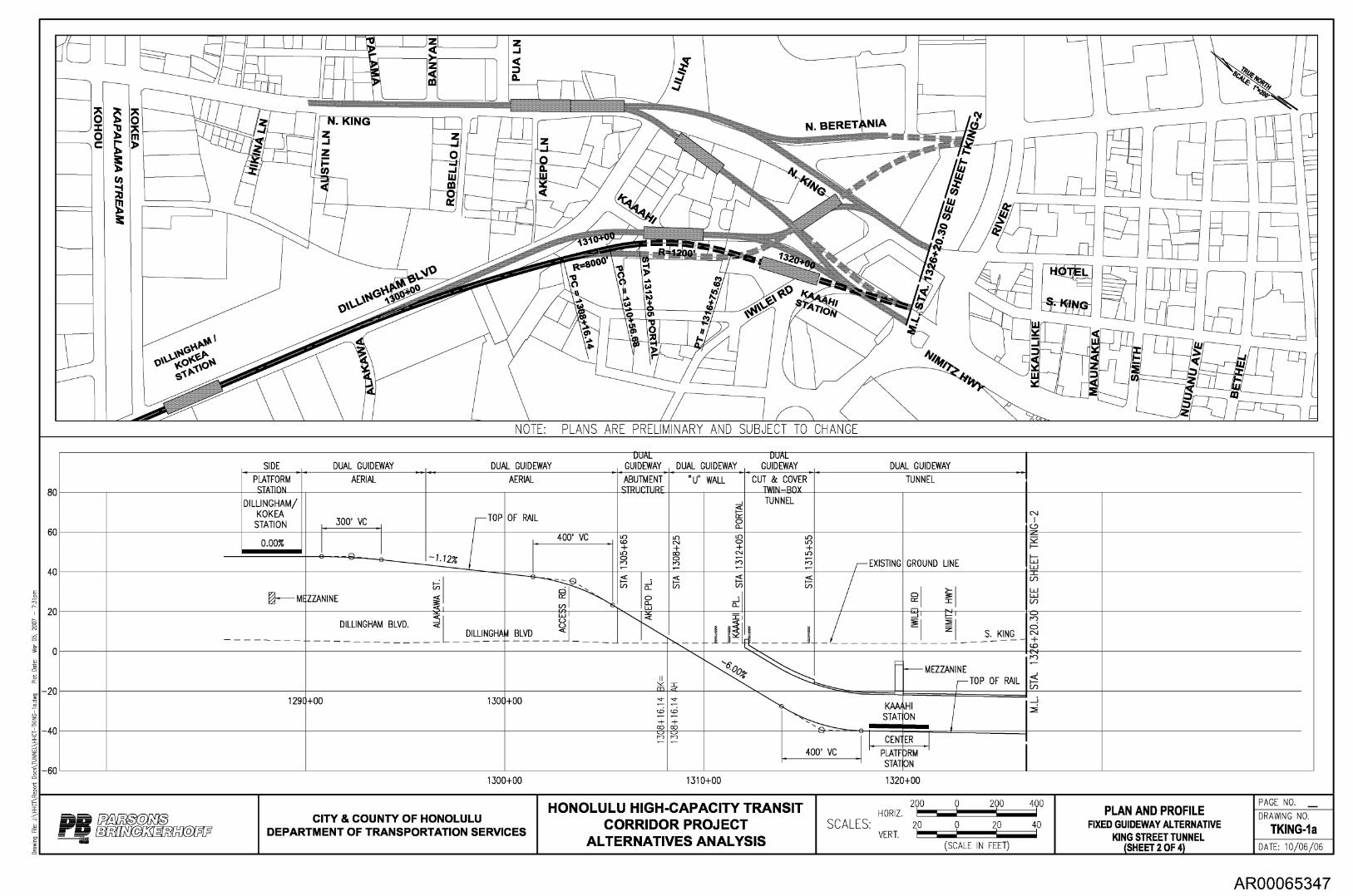
AR00065347
Mar
05,
20
07
1300+00 1310+00 1320+00
OHS PARS
NOTE: PLANS ARE PRELIMINARY AND SUBJECT TO CHANGE
DUAL DUAL SIDE DUAL GUIDEWAY DUAL GUIDEWAY GUIDEWAY DUAL GUIDEWAY GUIDEWAY DUAL GUIDEWAY
PLATFORM STATInN
AERIAL AERIAL ABUTMENT STRUCTURE
"U" WALL CUT 8c COVER TWIN—ROX
TUNNEL
DILLINGHAM/ KOKEA
STATION
0.00%
300' VC TOP
—1 .12Z
OF RAIL
400' VC c.oLf) C.9 + roc°
o 0_
0° + " r.,-) —
TUNNEL
LoL° + Lo ;7) EXISTING GROUND LINE
± ND
(f)
g < MEZZANINE
I Ix V)
0_ o L.,10- 0-
2 0
DILLINGHAM BLVD.
5L DILLINGHAM
L.L.1
C-3C
BLVD < 1 _ ______ _
I 1.
_ S. KING
II m = -.
MEZZANINE TOP OF RAIL
1290+00 1300+00 -,,- •—. CD
T co CT-C) ro
-,,- '-. CD
T CO
ro
...• K" STAT
HI ON
2
400' VC CEN
PLATF• RM STAT ON
HONOLULU HIGH-CAPACITY TRANSIT CORRIDOR PROJECT
ALTERNATIVES ANALYSIS
200 HORIZ.
SCALES: 20 VERT.
PLAN AND PROFILE FIXED GUIDEWAY ALTERNATIVE
KING STREET TUNNEL (SHEET 2 OF 4)
PAGE NO.
DRAWING NO.
TKING-1a DATE: 10/06/06
80
60
40
20
0
—20
—40
—60
BRINONER HOFF CITY & COUNTY OF HONOLULU
DEPARTMENT OF TRANSPORTATION SERVICES
0 200 400
0 20 40
(SCALE IN FEET)

PARS OHS BRINONER HOFF
, \
49
.. 1110, • •
_ s t
4. \ .11.
..- '' S
E -E• s
4
C . i ir
k#A4lir
'i:; N
lir
'. 32
6 %10 : 43
0443 7k
4 v 0.
1 .....
.....t.
I PT
= 1
328+
; , 6
8 ..
/ a
jc ir 4 , .4
c
= 1
41
+5
0.; • 1
11h
4
cram
a it i
t ip
am
mo
,„. ,
4di
rrir
p
r az
i nk,..
trria
-.
lir
44 I._
all
' im
ea
i
1 li a
l
.
1 11
AuN
i citE
A a
P Prczi I ,ir
.....a.R.L
A 1 t 1 1
-4:
a z
ffill 111 41
I i ,,,,,, nr
illit
smrn
i ami i
-1Y1
11
11
Irill milliril l i iir
alm alli i
r iliMil
a ..
miii
i
IP
sabs
Q IN
( VP
I, S
IM [
1 I
M O
g i il
l ea
l II W
it
tritir c
o 1.
im a
. o
wi E Atilli
ft 1
P7
. y
. m _
an
. ,
i i
i-116
1 0
m ,
z r -
1 I1•
. z
STY
- .
,•..
II , N
I
, sa _
.. 0i
_ oil
P
T i
- - -.
+ 84 '
4'
MU
NI&
t i
\
. B
ISH
OP
N M
,
pc =
1 5
1+7 0
.64 _0
:
ill
0 I;
- PT
= 1
35, 9
6: -0
co
L
,
' AL
AKEA
0 0.
_
Fla
1 -:N
r em
,
rrl
ia
n oto
m
I sm
RI
CHAR
DS ii
r i : P
C =
135
8+79
.7
It 0 i
MIL
ILA
NI g
I 2 0 '
ti 0
0 -I
M
. 6
r
1 q
%
014
4 *
v g tv
\ • c.
PU
NC
HB
OW
L ,
.:4 \
71.
0
'; '
C o 0
, \
t,.‘i‘\\r,c
o Jr ,
Oa
■%
Ift
1 t
c 01-4
-69t
V
- V
- *
L 4
1 c
. ,0 l'a
a *. .. ii
ve o
° S 0
, . v k
a lour
o cr
,"11
Pr
„, . ??
o
S
r .4 i 9
36? O
R .
f l i
v iv
-py
4.6 ?
Os ' 1 3,
9.:. .
I ' --
/ it
* A
iii i
ll ial
k t
3
1 10
1
.41
. I
41 01,
40, 4
. it A
lli w
i, „e„ - . ,
i 9
r
i 1110
‘, , c •
Ili
31
10
0 , /
H
--
_____
NOTE: PLANS ARE PRELIMINARY AND SUBJECT TO CHANGE
_ DUAL GUIDEWAY
_...
TUNNEL I I Y s•
CD Z Y I—
M
Lc) 0
(DO) ±±
0 c0
CD M
i EXISTING GROUND LINE
N-) z-
I
= D a 1
D z a w-I
cri 1-
oo=
_ '1x
--)
o
x
z
1
1= .
f
-
)
1
(
—
.) _- m ________ L ____ __
(E
S. KING - - -- -- __ D
cn°
(1)
'r-lo. 6 c.i ± co c.i
_ \ _.
TOP OF RAIL m
in o C.0 ±
MEZZANINE MEZZANINE
,—
cr)
rZ
-0.20%
KING/BETHEL STATION
-0.2 7
KING/PUNCHBOWL STATION
—
300' VC ..I CENTER .1
300 VC ..1 CENTER PLATFORM PLATFORM
1330+00 1340+00 1350+00 1360+00
1370+00
80
60
40
20
0
20
40
60
HONOLULU HIGH-CAPACITY TRANSIT CORRIDOR PROJECT
ALTERNATIVES ANALYSIS
200 HORIZ.
SCALES: 20 VERT.
PLAN AND PROFILE FIXED GUIDEWAY ALTERNATIVE
KING STREET TUNNEL (SHEET 3 OF 4)
PAGE NO.
DRAWING NO.
TKING-2 DATE: 10/06/06
CITY & COUNTY OF HONOLULU DEPARTMENT OF TRANSPORTATION SERVICES
0 200 400
0 20 40
(SCALE IN FEET)
AR00065348

1410+00 1420+00 1430+00
OHS PARS
NOTE: PLANS ARE PRELIMINARY AND SUBJECT TO CHANGE
II 021 DUAL GUIDEWAY DUAL GUIDEWAY DUAL GUIDEWAY
DUAL GUIDEWAY DUAL GUIDEWAY SIDE DUAL GUIDEWAY
TUNNEL = <r" CUT TIN
& COVER \1—BOX
'U' WALL ABUTMENT STRUCTURE
AERIAL PLATFORM STATION
AERIAL
L.r) co r--:
±
co co cO
± ()
TI- N N EL
KAPIOLAN I/ WARD N.
N)
CNJ I
-,i-
Fr) i +
0
0 a) +
.V + cpc) +
200 VC STATION
TOP OF RAIL
z
1—
LL1 I1=— .
■ 00 c..)
7 -- — I
•
ZT
a
.-7-
'
-Ft. I'.
L>
C,I
gd EXISTING GROUND LINE
I
L'i LY
. < aj
I co NI c=>
co ±
rZ ,- .:C. PO
Lo
kb'
IIIMIIIIIIIIIIIIIIIIIIIPIPP'' 11 - .. : 0 . 0____........
I 600' VC
HONOLULU HIGH-CAPACITY TRANSIT CORRIDOR PROJECT
ALTERNATIVES ANALYSIS
200 HORIZ.
SCALES: 20 VERT.
PLAN AND PROFILE FIXED GUIDEWAY ALTERNATIVE
KING STREET TUNNEL (SHEET 4 OF 4)
PAGE NO.
DRAWING NO.
TKING-3 DATE: 10/06/06
80
60
40
20
0
20
40
60
BRINONER HOFF CITY & COUNTY OF HONOLULU
DEPARTMENT OF TRANSPORTATION SERVICES
0 200 400
0 20 40
(SCALE IN FEET)
AR00065349
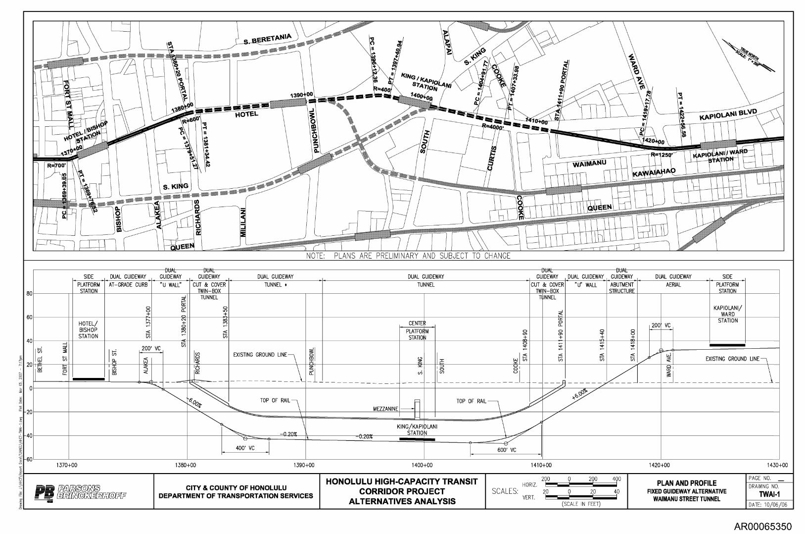
1370+00 1380+00 1390+00 1400+00 1410+00 1420+00 1430+00
ONS PARS 40
200 0 200 400 HORIZ.
SCALES: 20 0 20 VERT.
NOTE: PLANS ARE PRELIMINARY AND SUBJECT TO CHANGE
UUML UVML UUML UUML
SIDE DUAL GUIDEWAY GUIDEWAY GUIDEWAY DUAL GUIDEWAY DUAL GUIDEWAY GUIDEWAY DUAL GUIDEWAY GUIDEWAY DUAL GUIDEWAY SIDE
PLATFORM STATION
AT—GRADE CURB 'U WALL" CUT & COVER TWIN—BOX
TUNNEL * TUNNEL CUT TW
& COVER N —BOX
'U" WALL ABUTMENT STRUCTURE
AERIAL PLATFORM STATION
CD CD +
—1
o o_ CD
TUNNEL
o in + r-)
TUNNEL
_1 1—̀c
KAPIO LAN I/ WARD
HOTEL/ BISHOP STATION
N- r•-3 —
c., -F o rn _
1.--)c° — CENTE 0_0
CD ol -F + Ls"
CD o co+
200 VC STATION
PLATFO STATIO
M cr,° oo+
1 cr)
200' VC mcn EXISTING GROUND LINE
I-
CD -4- —
STA
141
.4- — a
-4- — a 1:1—
z L.L3 >. EXISTING GROUND LINE
= cr)
_______________________________
c._) o in
m =
' TOP OF RAIL
MEZZANINE
TOP OF RAIL
. .
• .,_ ,
1 ir. STATIO -0-20%
LAN I
400' VC
,—•••■pmmulimma • •
600' VC
rsi A I
HONOLULU HIGH-CAPACITY TRANSIT CORRIDOR PROJECT
ALTERNATIVES ANALYSIS (SCALE IN FEET)
PLAN AND PROFILE FIXED GUIDEWAY ALTERNATIVE
WAIMANU STREET TUNNEL
PAGE NO.
DRAWING NO.
TWAI-1 DATE: 10/06/06
80
60
40
20
0
20
40
60
DO BRINONER HOFF
CITY & COUNTY OF HONOLULU DEPARTMENT OF TRANSPORTATION SERVICES
AR00065350

Appendix B Details of Tunnel Boring Machine Types Available
Tunneling and Underground Stations Technical Report Page B-1 Honolulu High-Capacity Transit Corridor Project
AR00065351

Appendix B Details of Tunnel Boring Machine Types Available
Modern types of tunneling equipment and tunnel lining were assumed in the prior work undertaken in the early 1990's. At that time, the methods were considered the best-available but were still considered to be emerging technology. Since that time, and by the time this project is expected to start procurement under any form of contract delivery system, there will have been nearly 20 years of tunneling technology improvement since the early studies. Today, in 2006, the use of pressurized face TBMs and one-pass precast concrete tunnel lining proposed for projects like this, has become routine globally, as well as in the United States.
The following sections provide an overview of TBMs available today.
Tunnel Shield, Tunneling In Free Air Included here for completeness, the simplest tunneling system and generally the least costly TBM is a tunnel shield with the tunnel face open for excavation in soft ground. The shield provides protection for workers excavating at the tunnel face and permits the erection of a tunnel lining at the rear of the tunnel shield. Therefore excavation protection is installed around but not during tunnel driving in front of the machine except for stoppages. For much of the 20 th century, this was known as soft-ground tunneling with a shield, or a "shield-driven tunnel." The stability of the excavation at the front of the shield was very much dependent on the quality of the ground conditions at the tunnel face.
Tunneling has become increasingly mechanized over the years. Tunnels of typically smaller size are still built, dependent on ground conditions, with these open-faced shields using a wide variety of diggers that range from standard rubber-tired back hoes, to all sorts of customized hydraulically operated excavators, all with varying success. From this development in soft-ground tunneling equipment, the terminology "digger shield" emerged.
The tunnel boring machine shown in Figure B-1, a "digger shield," was used to tunnel sections of the Los Angeles transit system in the 1990's. A cross-section of this machine is shown in Figure B-2. Notable are the hydraulically operated breasting plates on periphery of top heading of tunnel shield and the hydraulic digger, which was adapted from backhoe and refined specifically for tunneling. The major disadvantage of this type of open-face is that the ground must be dewatered in advance of tunneling.
Tunneling and Underground Stations Technical Report Page B-3 Honolulu High-Capacity Transit Corridor Project
AR00065352

Figure B-1: Typical Open-Face "Digger Shield" for Tunneling
Figure B-2: Cross-section of Digger Shield
Tunnel Shield, Compressed Air Tunneling
The tunnel shield was adapted to use compressed air where either the ground was very weak, like soft clay, or the ground was saturated, such as sand that could not be dewatered. The compressed air could either be used to provide support to the tunnel face for impermeable materials such as clay or provide a counter balance to water pressure for more permeable materials; however, in high permeability soil, air loss could be significant and result in loss of face support resulting in collapse of the excavation. Using compressed air requires the pressurization of the full length of tunnel; therefore, workers in the tunnel are in a hyperbaric chamber. Decompression chambers are required
Page B-4 Tunneling and Underground Stations Technical Report Honolulu High-Capacity Transit Corridor Project
AR00065353

for both workers and materials and, depending on the air pressure applied, up to three decompression chambers could be required to permit 24 hour working. Until relatively recently, the incidence of decompression sickness was relatively frequent, particularly at higher working pressures and the incidence of bone necrosis resulted in many "sand hogs" becoming incapacitated at a young age. Gradually, tightening of statutory limits on compressed air working over the past twenty years has limited the use of open shields. As decompression times were lengthened and lower limits set on working pressures, so higher labor costs and concerns at the health impact of high compressed air pressures have reduced the usage of this type of shield.
As a specific example for this project, tunneling in the Nuuanu Stream area will be in very weak soil, which would have required compressed air tunneling if pressurized face tunneling technology had not developed. In addition to the use of compressed air for excavation protection, building protection by ground treatment or underpinning would be required generally for adjacent structures with shallow foundations as the zone and magnitude of settlement associated with open face shields would have had an impact on adjacent structures. Significant utility protection requirements would also have been of concern.
Pressurized Face Tunneling
Two main types of pressurized face TBMs for soft ground are now in use and there are a number of derivatives of each either developed or currently under development. The two principle types are the Earth Pressure Balance Machine (EPBM) and the Slurry Face Machine (SFM). A "mix-shield" is a manufacturer's product terminology and generally refers to a special TBM which combines the characteristics of both types of machine but which requires some downtime to change over from one type to the other.
Earth Pressure Balance Machine (EPBM)
Examples of EPBMs are shown in Figure B-3 with a cutterhead designed for soil. These machines were used on the LA County Metropolitan Transportation Authority's Metro Gold Line Eastside Extension.
The EPBM transmits the pressure to the face mechanically, through the soil grains, and is reduced by means of friction over the length of the screw conveyor. Control is obtained by matching the volume of soil displaced by forward motion of the shield with the volume of soil removed from the pressurized face by the screw conveyor and the soil finally is deposited (at ambient pressure) on the conveyor or muck car. There is direct connection between the face of the machine and the rear of the EPMB at the spoil discharge point. For protection against inflows, gates can be provided at the end of the Archimedes screw conveyor located immediately at the discharge point. Primary gate valves can also be installed at the bottom of the screw if sufficient space is available. During excavation these gates are normally left open to allow flow of spoil and there is always direct connection to the face during excavation. Figure B-4 provides a schematic of an EPBM.
Tunneling and Underground Stations Technical Report Page B-5 Honolulu High-Capacity Transit Corridor Project
AR00065354

Figure B-3: EPBM Used to Los Angeles Transit Courtesy LA County Metropolitan Transportation Authority
Clearly, the range of natural geologic conditions that will result in suitably plastic material to transfer the earth pressure to the face and, at the same time, suitably frictional to form the "sand plug" in the screw conveyor is rather limited — generally only combinations of fine sands and silts. It is also now common to provide soil conditioning to improve the material characteristics of the in-situ soil and to reduce the wear on roller cutters and bits at the head of the machine. This conditioning can achieve the plasticity needed to operate the machine effectively.
Page B-6 Tunneling and Underground Stations Technical Report Honolulu High-Capacity Transit Corridor Project
AR00065355

Tailskin Seal
Segment Erector Cutterhead Chamber
Cutterhead
Thrust Ram
Airtight Bulkhead
Airlock
Screw Conveyor Muck Transfer Conveyor
1,4F41,,dreirdlnirdre7
rid MNI11
1 1 O
/41
A
AirAWArardr:AVA:
N
N _a/ Alralralr
OPP' idL
WW!
Figure B-4: Cross-section of EPBM Courtesy of AFTES
Slurry Face Machine (SFM)
An example of a SFM at a fabrication plant in Germany is shown in Figure B-5. This machine was used for crossing under the Nile River during construction of the Cairo Metro tunnels in sands below the water table. This machine was subsequently modified to accommodate boulders formed from petrified forest in a subsequent phase of the project. The modifications included provision of a suitably sized opening in the cutterhead so that a crusher could be installed behind the cutterhead to break up the boulders.
The SFM transmits pressure to the face hydraulically through a viscous fluid formed by material cut in the face and mixed with a relatively dense slurry (basically bentonite and water). The face pressure can be either controlled directly by pressurization of the slurry or indirectly by means of a plenum chamber filled with air under pressure which acts directly on the bentonite slurry. This air bubble provides a more effective control of the face pressure and thus the excavated face. In conjunction with the slurry, the excavation can be controlled by means of pressure sensors in the cutterhead, pressure gages, and control valves via a piping system with pressure controlled by increasing or decreasing the air pressure. By this system a much more precise and more consistent pressure control is attained. Figure B-6 provides a cross section of a SFM.
Tunneling and Underground Stations Technical Report Page B-7 Honolulu High-Capacity Transit Corridor Project
AR00065356

Bubble Air ock Cutterhead Segment Erector
Bulkhead Thrust Ram Plenum Tailskin Seal
Agitator Cutterhead Chamber
41,-.`41K+1, Arz —ardr..0 ■11rardrirAlreAralrldrldri
fir
AVIir
X •A Xw4 '4& X
Slurr , Feed
— • . .
Slurry Return
X
Figure B-5: Slurry Face Machines Left courtesy of Herrenknecht; Right courtesy National Authority for Tunnels, Cairo, Egypt
The undesirable aspect of this system is that a separation plant has to be built and operated at the surface to separate the slurry from the soil cuttings for disposal and permit re-use of the slurry. Finding a site for the slurry separation that is satisfactory is difficult in urban areas and finding a final disposal sites acceptable to the public can be a challenge.
Figure B-6: Cross-section of SFM Courtesy AFTES
Page B-8 Tunneling and Underground Stations Technical Report Honolulu High-Capacity Transit Corridor Project
AR00065357

Tunnel breakouts
One of the higher risk areas of tunneling is at the tunnel breakout from the station or driving shaft. At this location, only partial face pressure can be developed in front of the face. The tunnel face pressure is contained by glands located around the outside of the tailskin and these have an unfortunate tendency to leak during the initial drive. At the start of the initial drive, operator experience of the machine in the anticipated ground conditions is limited and this experience can only be gained by understanding the ground response to tunneling operations which does take time to develop. A higher risk of ground loss can therefore be expected at these locations and development of the correct solution to the break-out/break-in design is fundamental to tunnel stability at these locations. A typical break out detail developed on Cairo Metro in sands below ground water level is shown in Figure B-7. Initially the simple design on the left was adopted. Unfortunately through experience, a more complex design which lowered risk had to be developed to overcome the shortcomings in the initial concept. This revised concept allowed for the problems associated with jet grouting where leakage paths can frequently arise due to necking of the jet grout columns.
'any :X
El lion
Ciroio
Jet grout
gram!
Jet
TIM.1 break
oul
Hard gel
?el
Inilial Rnised break -in::ul ncpI
Figure B-7: Tunnel Breakout Plan in Difficult Ground Conditions
Tunneling and Underground Stations Technical Report
Page B-9 Honolulu High-Capacity Transit Corridor Project
AR00065358

Figure B-8 shows an EPBM breaking into a station under ideal conditions.
Figure B-8: EPBM Completing Tunnel Drive
Tunnel Linings
Inherent with all of the TBM tunneling considered in this study is that the tunnel lining would be constructed of segmental precast concrete segments. Installed as tunneling progresses, the lining serves to maintain a stable tunnel opening immediately behind the machine. With the concrete segments designed and fabricated to specific quality standards, the lining is also the final lining, and is called a "one-pass" lining.
Water tightness and durability are the primary requirements of the tunnel lining, in addition to fundamental structural adequacy. The intent would be to have a dry tunnel on completion. State of the practice now is that a substantially dry, durable tunnel lining for a transit tunnel can be constructed with a one-pass segmental precast concrete tunnel lining fitted with a combination of hydrophilic and neoprene gaskets. The most recent example is the successful tunneling completed in 2006 for the Los Angeles MTA Eastside Extension, which completed 9,500 feet of 22 foot diameter tunnel.
In this study for Honolulu, other tunneling linings and materials were considered. Of emerging use in tunnels is steel fiber-reinforced concrete tunnel segments. Better durability is achievable for this type of segment, which has steel fibers as reinforcement instead of traditional reinforcing bars. For the alternatives analysis, it was not necessary to define the specific type of precast segments.
A less-costly initial tunnel lining of circular steel ribs with timber lagging could be used as an initial lining where ground and groundwater conditions permit. The final lining would be cast-in-place concrete. However, this type of tunnel lining was considered to
Page B-10 Tunneling and Underground Stations Technical Report Honolulu High-Capacity Transit Corridor Project
AR00065359

be not practical since it cannot be used with pressurized-face TBMs that are envisioned to be required and can result in significant ground settlement.
The following photographs show:
• Figure B-9: a completed precast lining in a dry tunnel with invert concrete completed ready for track concrete. Note that the walkway is formed of precast conduits sitting on steel brackets supported by bolts drilled into the linings.
• Figure B-10: Segments stored near the driving shaft arranged as single tunnel linings fitted with gaskets and ready to be lowered to the machine.
• Figure B-11: A completed precast lining.
Figure B-9: Detail of Precast Lined Twin Track Tunnel during Track Installation
Tunneling and Underground Stations Technical Report Page B-11 Honolulu High-Capacity Transit Corridor Project
AR00065360

Figure B-10: Storage of Precast Lining Segments at Tunnel Site
Figure B-11: One-pass Precast Concrete Line Single Track Tunnel
Design of the segment connections has developed over a number of years and now these are generally standardized as shown in Figure B-12. The design of the segments has been developed to achieve a fast installation time and tunnel linings have increased in length and therefore weight due to the development of segment erectors. Care has to be taken with the design of these connections particularly where high groundwater pressures and ram pressures must be considered. Similarly gaskets must be sized to suit the anticipated water pressures and the material constituents in the ground. Where there are significant
Page B-12
Tunneling and Underground Stations Technical Report Honolulu High-Capacity Transit Corridor Project
AR00065361

EPDM Gasket and/or Hydrophilic Gasket
levels of chloride ions, considerations should also be given to providing a membrane protection to the back of the lining to avoid corrosion of the rebar or spalling of concrete in the tunnel lining, as has been adopted in Singapore (Transit), Hong Kong (Transit) and Denmark (Storebaelt).
Figure B-12: Typical segment details at radial joint.
Relevant Precedents for Pressurized Face Tunneling
As examples of the state of the practice in tunneling, 3 tunnel projects are briefly described to illustrate what is possible for the Honolulu Transit Project.
Los Angeles MTA, Eastside Extension
Successful tunneling was completed recently (end 2006) for 1.8 miles of 22 foot diameter tunnel for extension of light rails transit service to the East Los Angeles. It is comparable to Honolulu in regard to tunneling directly under city streets in an important commercial are of the city. Two new EPBMs (see Figure B-3) were used successfully. A one-pass precast concrete tunnel lining was use and was designed for earthquake conditions. Two underground stations were built by cut and cover along that segment of tunnel.
Portland, Oregon Westside and Eastside CSO Projects
Two tunneling projects in Portland, Oregon used slurry-face type pressurized-face machines (SFM). The technical publication by Gribbon et al (2004) summarizes the unique contracting method for this project and the use of SFM in a weak rock. The first project ("Westside Combined Sewage Overflow (CSO) Project") constructed 3.5 miles of 15-foot-diameter tunnel. Figure B-13 shows the completed Westside tunnel with a curve and one-pass precast concrete lining completed using a SFM. The second project, which is in progress in 2007 ("Eastside CSO Project"), will use a 25-foot-diameter SFM for 6 miles of tunneling. These two project serve to demonstrate that tunneling using pressurized face TBMs are becoming a mature technology that can be used in difficult tunneling conditions. In the case of these Portland tunnels the tunnel ground conditions
Tunneling and Underground Stations Technical Report Page B-13 Honolulu High-Capacity Transit Corridor Project
AR00065362

consisted of an ancient river deposit of cobbles and gravel under or next to the Willamette River.
Figure B-13: Portland Westside CSO Tunnel with Curve
Port of Miami Tunnel, Miami, Florida
This is a proposed project that will construct a pair of bored roadway tunnels under the Main Channel of the Port of Miami, Miami, Florida. Relevance to tunneling in Honolulu is that the tunnel ground conditions have some similarities and pressurized face tunneling is being required. The project is in the early stage of procurement of a design-build concessionaire to undertake final design, construction, and operation of the facility.
Like Honolulu, the project is at or below sea level and the geologic conditions in both locations, despite the global distance between them, are primarily the result of climatic fluctuations resulting in sea level changes during the Pleistocene Epoch. Fluctuations of sea levels caused changes of depositional environments, various combinations of sediments and coral were created. In the case of Honolulu, deposition of basalt from active volcanic activity adds another dimension of complexity to the geologic setting. In some areas, the contacts between hard rock, weak rock, and soil are gradual; in other areas they are inter-fingered or inter-bedded.
Page B-14 Tunneling and Underground Stations Technical Report Honolulu High-Capacity Transit Corridor Project
AR00065363

For the Miami tunnel, it is a contract requirement that a pressurized face tunnel boring machine be used to excavate the bored tunnel. Either an EPBM or a SFM are considered feasible to provide the required face stability at the tunnel face. With the size of the excavated face on the order of 40 feet in diameter, and with the known variations in geology, the TBM will encounter both cemented and non-cemented materials in the face at the same time. This is likely to be a similar geologic condition for tunneling in downtown Honolulu, except that a smaller TBM, on the order of 21 feet diameter, will be required.
The Miami tunnel has construction issues that apply to those in Honolulu. With an EPBM it is critical that the face pressure be maintained at all times by forming and maintaining a satisfactory sand plug in the screw conveyor. With a SFM there is a risk of loss of slurry in zones of porous, high permeability limestone, resulting in a reduction in face pressure that will promote face instability and uncontrolled inflow of water and soil into the cutting chamber.
Tunneling and Underground Stations Technical Report Page B-15 Honolulu High-Capacity Transit Corridor Project
AR00065364
Appendix C Cost Estimate Details
Tunneling and Underground Stations Technical Report Page C-1 Honolulu High-Capacity Transit Corridor Project
AR00065365

Parsons Brinckerhoff Page 1 HONOLU2 HONOLULU TRANSIT PROJECT-KING ST. TNL 09/01/2006 14:45
ESTIMATE SUMMARY - COSTS & BID PRICES
Bid# Client# Quantity Bid Description
Unit Manhours
Direct Labor
Perm Matl
Constr Matt
Equip- Ment
Sub- Contr
Direct Total
Indirect Total Charge Cost
Total Cost Unit Price Markup
Balanced Bid Total Unit Price
Bid Price
Bid Total
21000 14,006.00 KING ST. OPTION #1 1315+55 TO 1408+90
21100 380.00 TUNATEL U-WALL 1308+25 TO 1312+05
21105 16,480.00 U-WALL SLURRY WALL SOE
21110 4,504.00 U-WALL STR. EXCAV.
21115 1,126.00 U-WALL INVERT CONCRETE 2. 5FT THICK
21120 985.00 U-WALL WALL CONC. 3.5FT THICK
21125 172.00 U-WALL WALKWAY CONCRETE 3.5 X3.5FT
21200 350.00 CUT&COVER BOX 1312+05 TO 1315+55
21205 31,122.00 CUT&COVER BOX SLURRY WALL SOE
21210 18,738.00 CUT&COVER BOX EXCAV.
21212 206.00 F&I TIEBACK ANCHORS
21215 2,064.00 CUT&COVER BOX INVERT CONC. 3.25FT THIC
21220 1,361.00 CUT&COVER BOX WALL CONC. 2.5FT THICK
21225 2,064.00 CUT&COVER ROOF CONC. 3.25FT THICK
21230 272.00 CUT&COVER WALKWAY CONC. 7X3FT
21235 467.00 CUT&COVER INTERIOR WALL CONC. 2FT THI
21240 1,271.00 CUT&COVER BACKFILL
21300 14,006.00
LF
LF
SF
BCY
CY
CY
CY
LF
SF
BCY
E4.
CY
CY
CY
CY
CY
CY
LF
605,359 43.22
26,934 70.88
11,559 0.70
2,174 0.48
3,381 3.00
8,642 877
1,175 6.84
68,643 196.12
20,274 0.65
9,038 0.48
5,476 2.65
13,209 9.71
12,874 6.24
1,869 6.87
5,655 12.11
244 0.19
425,579
38,237,776 2,730.10
1,694,521 4,459.27
727,040 44.12
126,573 2810
211,209 187.57
554,615 563.06
75,084 436.54
4,336,516 12,390.05
1,281,502 41.18
526,073 28.08
341,565 165.49
858,510 630.79
834,696 404.41
118,509 435.70
361,598 774.30
14,063 11.06
26,891,815
33,010,209 2,356.86
1,370,287 3,606.02
776,175 47.10
274,046 243.38
283,837 288.16
36,228 210.63
3,270,201 9,343.43
1,545,931 49.67
485,552 235.25
406,771 298.88
628,317 304.42
57,291 210.63
118,885 254.57
27,454 21.60
24,146,626
8,559,477 611.13
348,371 916.77
163,083 9.90
9,685 2.15
37,243 33.08
110,088 111.76
28,271 164.36
843,321 2,409.49
353,483 11.36
57,731 3.08
32,664 15.83
135,444 99.52
138,789 67.24
24,431 89.82
100,310 214.80
469 0.37
6,272,382
24,218,242 1,729.13
519,769 1,367.81
345,398 20.96
37,471 832
34,210 30.38
89,771 91.14
12,919 75.11
1,205,897 3,445.42
645,907 20.75
155,732 8.31
52,412 25.39
145,922 107.22
117,049 56.71
20,403 75.01
63,865 136.76
4,605 3.62
20,976,253
13,981,896 998.28
554,165 1,45833
464,085 2816
90,080 20.00
3,201,290 9,146.54
766,530 24.63
374,760 20.00
2,060,000 10,000.00
6,955,039
118,007,599 8,425.50
4,487,113 11,80819
2,475,782 150.23
263,810 5857
556,708 494.41
1,038,311 1,054.12
152,503 886.64
12,857,225 36,734.93
4,593,353 147.59
1,114,296 59.47
2,060,000 10,000.00
912,194 441.95
1,546,648 1,136.41
1,718,851 832.78
220,634 811.16
644,658 1,380.42
46,591 36.66
85,242,113
118,007,599
4,487,113
12,857,225
85,242,113
8,425.50 35.0 %
11,80819
36,734.93
6,086.11
41,302,660 2,948.93
159,310,259 11,374.43 11,374.43 159,310,266.58
AR00065366

Parsons Brinckerhoff Page 2 HONOLU2 HONOLULU TRANSIT PROJECT-KING ST. TNL 09/01/2006 14:45
ESTIMATE SUMMARY - COSTS & BID PRICES
Bid# Client# Quantity Bid Description
Unit Manhours
Direct Labor
Perm Matl
Constr Matt
Equip- Ment
Sub- Direct Contr Total
Indirect Total Charge Cost
Total Cost Balanced Bid Unit Price Markup Total Unit Price
Bid Bid Price Total
KING ST. TUNNEL EXCAr. &LINING 30.39 1,920.02 1,724.02 447.84 1,497.66 496.58 6,086.11
21305 1.00 LS 14,946 927,816 448,657 170,563 750,000 2,297,036 SETUP PORTAL AREA@ 1315+55 14,946.88 927,815.78 448,657.19 170,562.63 750,000.00 2,297,035.60
21310 1.00 LS 1,435 90,213 39,625 8,447 138,285 SETUP PORTAL AREA@ 1408+90 1,435.94 90,212.97 39,624.91 8,447.32 138,285.20
21315 1.00 EA 30,046 1,865,895 411,530 9,009,608 11,287,032 EPBM@1315+55 30,046.80 1,865,894.92 411,529.56 9,009,607.50 11,287,031.98
21320 1.00 SET 19,702 1,200,013 3,360 84,249 387,384 1,675,006 TRAILING GEAR@ 1315+55 19,702.40 1,200,013.14 3,360.00 84,24893 387,383.90 1,675,005.97
21325 1.00 LS 1,446,500 1,446,500 PREPARE PORTAL@1315+ 55 1,446,500.00 1,446,500.00
21330 1.00 LS 1,402,500 1,402,500 PREPARE PORTAL@ 1408+90 1,402,500.00 1,402,500.00
21335 1.00 LS 4,031 247,129 17,299 77,186 341,614 RAIL EQUIPMENT@ 1315+55 4,031.00 247,128.65 17,299.01 77,186.46 341,614.12
21340 14,006.00 LF 355,416 22,560,749 24,143,266 5,271,022 11,323,065 3,356,039 66,654,140 MINE TUNNELS 1315+55 TO 1408+90 25.38 1,610.79 1,723.78 376.34 808.44 239.61 4,758.97
21400 300.00 LF 57,139 3,612,700 2,792,009 759,141 1,000,748 2,724,561 10,889,159 10,889,159 36,297.20 CUT&COVER BOX 1408+90 TO 1411+90 190.47 12,042.33 9,306.70 2,530.47 3,335.83 9,081.87 36,297.20
21405 25,826.00 SF 16,900 1,067,877 1,325,819 294,060 536,294 704,221 3,928,271 CUT&COVER BOX SLURRY WALL SOE 0.65 41.35 51.34 11.39 20.77 27.27 152.11
21410 15,517.00 BCY 7,484 435,642 47,807 128,963 310,340 922,752 CUT&COVER BOX EXCAr. 0.48 28.08 3.08 8.31 20.00 59.47
21415 171.00 E4 1,710,000 1,710,000 F&I TIEBACK ANCHORS 10,000.00 10,000.00
21420 1,769.00 CY 4,760 297,478 416,355 30,627 46,477 790,937 CUT&COVER BOX INVERT CONC. 3.25FT THIC 2.69 168.16 235.36 17.31 26.27 447.11
21425 1,167.00 CY 11,334 737,053 348,735 129,770 124,992 1,340,550 CUT&COVER BOX WALL CONC. 2.5FT THICK 9.71 631.58 298.83 111.20 107.11 1,148.71
21430 1,769.00 CY 10,455 679,142 538,514 139,047 94,329 1,451,032 CUT&COVER ROOF CONC. 3.25FT THICK 5.91 383.91 304.42 7860 53.32 820.26
21435 233.00 CY 1,372 85,927 48,985 19,916 13,945 168,772 CUT&COVER WALKWAY CONC. 7X3FT 5.89 368.78 210.23 85.48 59.85 724.35
21440 400.00 CY 4,726 303,551 101,829 97,713 53,774 556,868 CUT&COVER INTERIOR WALL CONC. 2FT THI 11.82 75888 254.57 244.28 134.44 1,392.17
AR00065367

Parsons Brinckerhoff Page 3 HONOLU2 HONOLULU TRANSIT PROJECT-KING ST. TNL 09/01/2006 14:45
ESTIMATE SUMMARY - COSTS & BID PRICES
Bid# Client# Quantity Bid Description
Unit Manhours
Direct Labor
Perm Matl
Constr Matt
Equip- Ment
Sub- Contr
Direct Total
Indirect Total Charge Cost
Total Cost Unit Price Markup
Balanced Bid Total Unit Price
Bid Price
Bid Total
21445 545.00 CY 104 6,030 11,772 201 1,975 19,979 CUT&COVER BACKE= 0.19 11.06 21.60 0.37 3.62 36.66
21500 350.00 LF 27,061 1,702,224 1,431,087 336,262 515,576 546,841 4,531,990 4,531,990 12,94854 TUNNEL U-WALL 1411+90 TO 1415+40 77.32 4,863.50 4,088.82 960.75 1,4 73.07 1,562.40 12,94854
21505 15,280.00 SF 10,891 684,580 831,251 151,629 331,328 447,281 2,446,069 U-WALL SLURRY WALL SOE 0.71 44.80 54.40 9.92 21.68 29.27 160.08
21510 4,978.00 BCY 2,403 139,885 10,705 41,412 99,560 291,561 U-WALL EXCAVATION 0.48 2810 2.15 8.32 20.00 5857
21515 1,037.00 CY 3,147 196,615 252,511 28,595 31,924 509,646 U- WALLINVERT CONCRETE 2.5 FT THICK 3.03 189.60 243.50 2757 30.79 491.46
21520 1,089.00 CY 9,552 613,012 313,835 121,661 99,173 1,14 7,681 U-WALL WALL CONCRETE 3.5 FT THICK 877 562.91 288.19 111.72 91.07 1,053.89
21525 159.00 CY 1,067 68,132 33,490 23,672 11,739 137,033 U-WALL WALKWAY CONCRETE 3.5X3.5F7' 6.71 428.50 210.63 14888 73.83 861.84
22000 12,466.00 LF 575,032 36,297,961 30,740,539 8,673,038 23,162,928 14,193,099 113,067,566 113,067,566 9,070.08 39,573,648 152,641,214 12,244.60 12,244.60 152,641,183.60 KING ST. OPTION #2 1348+50 TO 1408+90 46.13 2,911.76 2,465.95 695.74 1,858.09 1,138.54 9,070.08 35.0 % 3,174.53
22100 400.00 LF 32,400 2,038,618 1,650,895 400,062 639,266 690,857 5,419,699 5,419,699 13,549.25 TUNNEL U-WALL 1341+00 T01345+00 81.00 5,096.55 4,127.24 1, 000.1 6 1,598.17 1,727.14 13,549.25
22105 20,736.00 SF 14,179 893,374 967,831 203,193 433,128 577,077 3,074,603 U-WALL SLURRY WALL SOE 0.68 43.08 46.67 9.80 20.89 27.83 14827
22110 5,689.00 BCY 2,746 159,873 12,233 47,330 113,780 333,216 U-WALL STR. EXCAV. 0.48 2810 2.15 832 20.00 5857
22115 1,185.00 CY 3,392 211,101 288,272 29,486 32,643 561,502 U-WALL INVERT CONCRETE 2. 5FT THICK 2.86 178.14 243.27 24.88 27.55 473.84
22120 1,244.00 CY 10,875 697,885 358,557 131,036 112,929 1,300,407 U-WALL WALL CONC. 3.5FT THICK 874 561.00 288.23 105.33 90.78 1,045.34
22125 172.00 CY 1,206 76,385 36,235 24,114 13,237 149,970 U-WALL WALKWAY CONCRETE 3.5 X3.5FT 7.02 444.10 210.67 140.20 76.96 871.92
22200 350.00 LF 71,407 4,502,901 3,310,878 876,986 1,281,021 3,130,293 13,102,079 13,102,079 37,434.51 CUT&COVER BOX 1345+00 TO 1348+50 204.02 12,865.43 9,459.65 2,505.67 3,660.06 8,943.69 37,434.51
22205 33,516.00 SF 21,718 1,3 73,294 1,538,697 379,520 695,306 911,073 4,897,890 CUT&COVER BOX SLURRY WALL SOE 0.65 40.97 45.91 11.32 20.75 27.18 146.14
22210 20,961.00 BCY 10,387 605,200 66,411 179,501 419,220 1,2 70,333 CUT&COVER BOX EXCAV. 0.50 28.87 3.17 8.56 20.00 60.60
AR00065368

Parsons Brinckerhoff Page 4 HONOLU2 HONOLULU TRANSIT PROJECT-KING ST. TNL 09/01/2006 14:45
ESTIMATE SUMMARY - COSTS & BID PRICES
Bid# Client# Quantity Bid Description
Unit Manhours
Direct Labor
Perm Matl
Constr Matt
Equip- Ment
Sub- Direct Contr Total
Indirect Total Charge Cost
Total Cost Balanced Bid Unit Price Markup Total Unit Price
Bid Bid Price Total
22215 386.00 F&I TIEBACK ANCHORS
E4
1,800,000 1,800,000
4,663.21 4,663.21
22220 2,064.00 CY 5,476 341,565 485,552 32,664 52,412 912,194 CUT&COVER BOX INVERT CONC. 3.25FT THIC 2.65 165.49 235.25 15.83 25.39 441.95
22225 1,3 61.00 CY 13,209 858,510 406,771 135,444 145,922 1,546,648 CUT&COVER BOX WALL CONC. 2. 5FT THICK 9.71 630.79 298.88 99.52 107.22 1,136.41
22230 2,064.00 CY 12,874 834,696 628,317 138,789 117,049 1,718,851 CUT&COVER ROOF CONC. 3.25FT THICK 6.24 404.41 304.42 67.24 56.71 832.78
22235 272.00 CY 1,413 89,378 57,184 22,559 14,305 183,427 CUT&COVER WALKWAY CONC. 7X3FT 5.20 328.60 210.24 82.94 52.59 674.36
22240 467.00 CY 5,655 361,598 118,885 100,310 63,865 644,658 CUT&COVER INTERIOR WALL CONC. 2FT THI 12.11 774.30 254.57 214.80 136.76 1,380.42
22245 3,494.00 CY 670 38,659 75,472 1,289 12,659 128,080 CUT&COVER BACKFILL 0.19 11.06 21.60 0.37 3.62 36.66
22300 12,466.00 LF 386,457 24,408,886 21,491,970 6,299,500 19,715,632 7,100,546 79,01 6,534 79,01 6,534 6,338.56 KING ST. TUNNEL EXC.&LINING 31.00 1,958.04 1,724.05 505.33 1,581.55 569.59 6,33856
22305 1.00 LS 14,946 92 7,81 6 448,657 170,563 750,000 2,297,036 SETUP PORTAL AREA@ 1348+50 14,946.88 92 7,815.78 448,65 7.19 170,562.63 750,000.00 2,297,035.60
22310 1.00 LS 1,435 90,213 39,625 8,447 138,285 SETUP PORTAL AREA@ 1408+90 1,435.94 90,212.97 39,624.91 8,44 7.32 138,285.20
22315 1.00 EA 30,046 1,865,895 411,530 9,009,608 11,287,032 EPBM@1348+50 30,046.80 1,865,894.92 411,529.56 9,009,607.50 11,287,031.98
22320 1.00 SET 19,702 1,200,013 3,360 84,249 387,384 1,675,006 TRAILING GEAR@ 1348+50 19,702.40 1,200,013.14 3,3 60.00 84,24893 387,383.90 1,675,005.97
22325 1.00 LS 1,446,500 1,446,500 PREPARE PORTAL@1348+ 50 1,446,500.00 1,446,500.00
22330 1.00 LS 1,402,500 1,402,500 PREPARE PORTAL@ 1408+90 1,402,500.00 1,402,500.00
22335 1.00 LS 4,031 247,129 17,299 77,186 341,614 RAIL EQUIPMENT@ 1348+50 4,031.00 247,128.65 17,299.01 77,186.46 341,614.12
22340 12,466.00 LF 316,294 20,077,821 21,488,610 5,298,140 10,062,444 3,501,546 60,428,562 MINE TUNATELS 1348+50 TO 1408+90 25.37 1,610.61 1,723.78 425.01 807.19 280.89 4,847.47
22400 300.00 LF 57,706 3,645,331 2,855,709 760,229 1,011,433 2,724,561 10,997,2 64 10,997,264 3 6,65 7.55 CUT&COVER BOX 1408+90 TO 1411+90 192.35 12,151.10 9,519.03 2,534.10 3,3 71.44 9,081.87 36,657.55
22405 25,826.00 SF 16,900 1,067,877 1,325,819 294,060 536,294 704,221 3,928,271
AR00065369
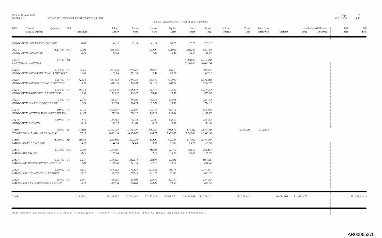
Parsons Brinckerhoff Page 5 HONOLU2 HONOLULU TRANSIT PROJECT-KING ST. TNL 09/01/2006 14:45
ESTIMATE SUMMARY - COSTS & BID PRICES
Bid# Client# Quantity Bid Description
Unit Manhours
Direct Labor
Perm Matl
Constr Matt
Equip- Ment
Sub- Contr
Direct Total
Indirect Total Charge Cost
Total Cost Unit Price Markup
Balanced Bid Total Unit Price
Bid Bid Price Total
CUT&COVER BOX SLURRY WALL SOE 0.65 41.35 51.34 11.39 20.77 27.27 152.11
22410 15,517.00 BCY 7,484 435,642 47,807 128,963 310,340 922,752 CUT&COVER BOX EXCAr. 0.48 28.08 3.08 8.31 20.00 59.47
22415 171.00 E4 1,710,000 1,710,000 F&I TIEBACK ANCHORS 10,000.00 10,000.00
22420 1,769.00 CY 4,760 297,478 416,355 30,627 46,477 790,937 CUT&COVER BOX INVERT CONC. 3.25FT THIC 2.69 168.16 235.36 17.31 26.27 447.11
22425 1,1 67.00 CY 11,334 737,053 348,735 129,770 124,992 1,340,550 CUT&COVER BOX WALL CONC. 2.5FT THICK 9.71 631.58 298.83 111.20 107.11 1,148.71
22430 1,769.00 CY 10,455 679,142 538,514 139,047 94,329 1,451,032 CUT&COVER ROOF CONC. 3.25FT THICK 5.91 383.91 304.42 7860 53.32 820.26
22435 233.00 CY 1,372 85,927 48,985 19,916 13,945 168,772 CUT&COVER WALKWAY CONC. 7X3FT 5.89 368.78 210.23 85.48 59.85 724.35
22440 400.00 CY 4,726 303,551 101,829 97,713 53,774 556,868 CUT&COVER INTERIOR WALL CONC. 2FT THI 11.82 75888 254.57 244.28 134.44 1,392.17
22445 3,494.00 CY 670 38,662 75,473 1,289 12,660 128,083 CUT&COVER BACKFILL 0.19 11.07 21.60 0.37 3.62 36.66
22500 350.00 LF 27,061 1,702,224 1,431,087 336,262 515,576 546,841 4,531,990 4,531,990 12,94854 TUNNEL U-WALL 1411+90 TO 1415+40 77.32 4,863.50 4,088.82 960.75 1,4 73.07 1,562.40 12,94854
22505 15,280.00 SF 10,891 684,580 831,251 151,629 331,328 447,281 2,446,069 U-WALL SLURRY WALL SOE 0.71 44.80 54.40 9.92 21.68 29.27 160.08
22510 4,978.00 BCY 2,403 139,885 10,705 41,412 99,560 291,561 U-WALL STR. EXCAr. 0.48 2810 2.15 832 20.00 5857
22515 1,037.00 CY 3,147 196,615 252,511 28,595 31,924 509,646 U-WALL INVERT CONCRETE 2. 5FT THICK 3.03 189.60 243.50 27.57 30.79 491.46
22520 1,089.00 CY 9,552 613,012 313,835 121,661 99,173 1,14 7,681 U-WALL WALL CONCRETE 3.5 FT THICK 877 562.91 288.19 111.72 91.07 1,053.89
22525 159.00 CY 1,067 68,132 33,490 23,672 11,739 137,033 U-WALL WALKWAY CONCRETE 3.5 X3.5FT 6.71 428.50 210.63 14888 73.83 861.84
Totals: 1,180,391 74,535,737 63,750,748 17,232,514 47,381,170 28,174,994 231,075,165 231,075,165 80,876,307 311,951,472 311,951,450.18
Code between Balanced Bid & Bid Price: U=Unbalanced, F=Frozen, C=Closing Biditem (item to absorb unbalancing differences).
AR00065370

Parsons Brinckerhoff
Page 6 HONOLU2 HONOLULU TRANSIT PROJECT-KING ST. TNL
09/01/2006 14:45
ESTIMATE SUMMARY - COSTS & BID PRICES
Bid# Client# Quantity Unit
Direct Perm Constr Equip- Sub- Direct Indirect Total Total Cost Balanced Bid Bid Bid Bid Description
Manhours
Labor Matl Matt Ment Contr Total Charge Cost Unit Price
Markup
Total Unit Price Price Total
[bracketed numbers represent adjusted quantities] ** in front of the Bid item indicates a Non-Additive item
Markup on Resource Costs 80,876,307
********* TOTAL
JOB > 1,180,391 74,535,737 63,750,748 17,232,514 47,381,170 28,174,994 231,075,165 231,075,165 80,876,307
311,951,472 311,951,450.18
Spread Indirects On TOTAL COST
Estimate Notes Bid Date:
Owner: Estimator in Charge:
Desired Bid (if spec ified)= Last Summary on 09/01/2006 at 2:23 PM. Last Spread on 09/01/2006 at 2:23 PM.
Spread Markups On TOTAL COST Spread Addons&Bonds On TOTAL COST
Engineering Firm:
0.00 Sort: Hold Acct: N Sub em: Y NonAdd: N
NOTE: Biditems that are sub e s (have a parent biditem) are printed in italics.
AR00065371

Parsons Brinckerhoff Page 1 HONOLU1 HONOLULU TRANSIT PROJECT #1 06/15/2006 14:18
ESTIMATE SUMMARY - COSTS & BID PRICES
Bid# Client# Quantity Unit
Direct Perm Constr Equip- Sub- Direct Indirect Total Total Cost Balanced Bid Bid Bid Bid Description
Manhours
Labor Matl Matt Ment Contr Total Charge Cost Unit Price
Markup
Total Unit Price Price Total
21000 10,110.00 LF DILLINGHAM- BERETANIA-S.KING ST. TUN
21100 380.00 LF DILLINGHAM- BERETANIA-S.KING PORTAL@I
21110 11,520.00 SF SLURRY WALL@I313+30
21120 7,262.00 BCY PORTAL EXCAV.@I313+30
21130 2,118.00 CY PORTAL INVERT CONC. @I313+30
21140 739.00 CY PORTAL WALL CONC @I313+30.
21200 260.00 LF BERETANIA-SOUTH KING PORTAL@I371+00
21210 7,560.00 SF SLURRY WALL @1371+00
21220 4,969.00 BCY PORTAL EXCAV. @1371+00
21230 1,449.00 CY PORTAL INVERT CONC. @1371+00
21240 506.00 CY PORTAL WALL CONC. @1371+00
21300 350.00 LF DILLINGHAM-BERETANIA-S.KING CUT&COVE
21310 29,014.00 SF CUT&COVER SLURRY WALL@I313+30
21320 18,116.00 BCY CUT&COVER EXCAV.@I313+30
21325 152.00 E4 F&I TIEBACK ANCHORS@I313+ 30
21330 1,951.00 CY CUT&COVER INVERT SLAB CONC.@I 313+30
21335 272.00 CY CUT&COVER WALKWAY CONC.@I313+30
21340 965.00 CY
487,393 48.21
25,377 66.78
9,027 0.78
3,462 0.48
5,088 2.40
7,799 10.55
17,572 67.59
5,907 0.78
2,390 0.48
4,009 2.77
5,264 10.40
59,571 170.20
19,448 0.67
8,718 0.48
5,025 2.58
1,777 6.53
9,064
30,717,243 3,038.30
1,586,674 4,175.46
565,458 49.08
201,436 27.74
320,810 151.47
498,970 675.20
1,098,270 4,224.12
370,698 49.03
139,108 28.00
250,761 173.06
337,703 667.40
3,750,423 10,715.49
1,228,399 42.34
507,405 2801
314,427 161.16
113,277 416.46
588,649
25,235,965 2,496.14
1,263,177 3,324.15
551,113 47.84
494,536 233.49
217,528 294.35
849,763 3,268.32
362,611 47.96
338,283 233.46
148,869 294.21
2,869,995 8,199.99
1,315,935 45.36
455,620 233.53
57,291 210.63
284,422
7,110,527 703.32
322,786 849.44
146,481 12.72
22,158 3.05
48,456 22.88
105,691 143.02
239,265 920.25
96,294 12.74
15,302 3.08
40,980 2828
86,690 171.32
841,526 2,404.36
335,706 11.57
55,815 3.08
47,903 24.55
31,549 115.99
136,889
20,716,455 2,049.11
438,997 1,155.25
245,937 21.35
59,580 820
49,659 23.45
83,820 113.42
299,107 1,150.41
161,574 21.37
41,172 8.29
39,860 27.51
56,501 111.66
1,081,237 3,089.25
605,022 20.85
150,181 8.29
48,096 24.65
19,584 72.00
99,912
12,946,814 1,280.59
545,497 1,435.52
400,257 34.74
145,240 20.00
364,743 1,402.86
265,363 35.10
99,380 20.00
2,849,619 8,141.77
967,299 33.34
362,320 20.00
1,520,000 10,000.00
96,727,004 9,567.46
4,157,130 10,939.82
1,909,245 165.73
428,414 5899
913,462 431.29
906,009 1,225.99
2,851,148 10,965.95
1,256,540 166.21
294,962 59.36
669,883 462.31
629,763 1,244.59
11,392,801 32,550.86
4,452,360 153.46
1,075,721 59.38
1,520,000 10,000.00
866,045 443.90
221,701 815.08
1,109,871
96,727,004
4,157,130
2,851,148
11,392,801
9,567.46 35.0 %
10,939.82
10,965.95
32,550.86
33,854,451 3,348.61
130,581,455 12,916.07 12,916.07 130,581,467.70
AR00065372

Parsons Brinckerhoff Page 2 HONOLU1 HONOLULU TRANSIT PROJECT #1 06/15/2006 14:18
ESTIMATE SUMMARY - COSTS & BID PRICES
Bid# Client# Quantity Unit Bid Description Manhours
Direct Labor
Perm Matl
Constr Matt
Equip- Ment
Sub- Direct Contr Total
Indirect Total Charge Cost
Total Cost Balanced Bid Unit Price Markup Total Unit Price
Bid Bid Price Total
CUT&COVER WALL CONC.@11313+30 9.39 610.00 294.74 141.85 103.54 1,150.13
21345 311.00 CY 3,558 228,985 79,173 82,906 40,762 431,827 CUT&COVER INTERIOR WALL CONC.@I313+3 11.44 736.29 254.58 266.58 131.07 1,388.51
21350 1,672.00 CY 10,729 697,321 508,986 142,842 94,116 1,443,265 CUT&COVER ROOF CONC.@I313+30 6.42 417.06 304.42 85.43 56.29 863.20
21355 7,804.00 CY 1,248 71,960 168,570 7,916 23,564 272,010 CUT&COVER BACKFILL@I313+ 30 0.16 9.22 21.60 1.01 3.02 34.86
21360 350.00 LF 58,690 3,699,684 2,822,208 823,312 1,061,145 2,799,249 11,205,598 11,205,598 32,015.99 DILLINGHAM-BERETANIA-S.KING CUT&COVE 167.69 10,570.52 8,063.45 2,352.32 3,031.84 7,997.85 32,015.99
21365 28,578.00 SF 19,177 1,212,178 1,349,668 331,019 596,598 922,509 4,411,972 CUT&COVER SLURRY WALL@I371+00 0.67 42.42 47.23 11.58 20.88 32.28 154.38
21370 17,837.00 BCY 8,584 499,591 54,955 147,867 356,740 1,059,153 CUT&COVER EXCAV.@1371+00 0.48 2801 3.08 8.29 20.00 59.38
21372 152.00 E4 1,520,000 1,520,000 F&I TIEBAACKS@I371+ 00 10,000.00 10,000.00
21375 1,951.00 CY 5,153 322,522 455,620 48,667 50,137 876,945 INVERT SLAB CONC.@I 371+00 2.64 165.31 233.53 24.94 25.70 449.48
21378 272.00 CY 1,777 113,277 57,291 31,549 19,584 221,701 WALKWAY CONC.@1371+ 00 6.53 416.46 210.63 115.99 72.00 815.08
21380 965.00 CY 9,064 588,649 284,422 127,285 99,912 1,100,267 WALL CONC.@1371+00 9.39 610.00 294.74 131.90 103.54 1,140.17
21382 311.00 CY 3,558 228,985 79,173 82,906 40,762 431,827 INTERIOR WALL CONC.@1371+00 11.44 736.29 254.58 266.58 131.07 1,388.51
21385 1,672.00 CY 10,729 697,321 508,986 142,843 94,116 1,443,266 ROOF CONC.@1371+ 00 6.42 417.06 304.42 85.43 56.29 863.20
21390 4,030.00 CY 644 37,161 87,050 4,088 12,169 140,467 CUT&COVER BACKFILL@ 1371+00 0.16 9.22 21.60 1.01 3.02 34.86
21400 10,110.00 LF 326,181 20,582,193 17,430,822 4,883,638 17,835,970 6,387,705 67,120,327 67,120,327 6,639.00 BERETANIA-SOUTH KING TUNNEL EXC.&LINI 32.26 2,035.83 1,724.12 483.05 1,764.19 631.82 6,639.00
21410 1.00 LS 15,010 932,686 455,931 170,563 750,000 2,309,180 SETUP PORTAL AREA@I 316+ 80 15,010.88 932,685.85 455,931.04 170,562.63 750,000.00 2,309,179.52
21415 1.00 LS 1,435 90,213 39,625 8,447 138,285 SETUP PORTAL AREA@I 371+ 00 1,435.94 90,213.07 39,624.91 8,447.32 138,285.30
21420 1.00 EA 30,046 1,865,896 397,469 9,009,607 11,272,971 EPBM@I316+80 30,046.80 1,865,896.21 397,46873 9,009,606. 50 11,272,971.44
AR00065373

Parsons Brinckerhoff
Page 3 HONOLU1 HONOLULU TRANSIT PROJECT #1
06/15/2006 14:18
ESTIMATE SUMMARY - COSTS & BID PRICES
Bid# Client# Quantity Bid Description
Unit Manhours
Direct Labor
Perm Matl
Constr Matt
Equip- Ment
Sub- Contr
Direct Total
Indirect Total Charge Cost
Total Cost Unit Price Markup
Balanced Bid Total Unit Price
Bid Price
Bid Total
21425 1.00 SET 19,702 1,200,013 3,360 84,249 387,384 1,675,006 TRAILING GEAR@1316+ 80 19,702.40 1,200,013.14 3,360.00 84,24893 387,383.90 1,675,005.97
21430 1.00 LS 1,446,500 1,446,500 PREPARE PORTAL@I 316+80 1,446,500.00 1,446,500.00
21432 1.00 LS 1,402,500 1,402,500 PREPARE PORTAL @1371+00 1,402,500.00 1,402,500.00
21435 1.00 LS 4,031 247,129 17,299 77,186 341,614 RAIL EQUIPMENT@I 316+ 80 4,031.00 247,128.65 17,299.01 77,186.46 341,614.12
21450 10,110.00 LF 255,954 16,246,256 17,427,462 3,889,065 8,182,783 2,788,705 48,534,271 MINE TUNNELS 1316+80 TO 1371+00 (2-TUNAT 25.32 1,606.95 1,723.78 384.68 809.38 275.84 4,800.62
22000 5,080.00 LF 373,159 23,444,623 16,791,055 5,301,868 17,067,941 11,219,453 73,824,940 73,824,940 14,532.47 25,838,729 99,663,669 19,618.83 19,618.83 99,663,656.40 HOTEL-WAIMANU-KAPIOLANI ST. TUNNEL( 73.46 4,615.08 3,305.33 1,043.67 3,359.83 2,208.55 14,532.47 35.0 % 5,086.36
22100 320.00 LF 29,896 1,860,341 1,889,736 355,339 485,265 595,559 5,186,240 5,186,240 16,207.00 HOTEL-WAIMANU-KAPIOLANI PORTAL @138 93.43 5,813.57 5,905.43 1,110.43 1,516.45 1,861.12 16,207.00
22110 9,720.00 SF 7,613 476,911 866,543 123,557 207,498 340,739 2,015,248 SLURRY WALL@I380+20 0.78 49.06 89.15 12.71 21.35 35.06 207.33
22120 12,741.00 BCY 6,074 353,413 38,875 104,532 254,820 751,641 PORTAL EXCAV@I380+20 0.48 27.74 3.05 820 20.00 5899
22130 3,567.00 CY 9,033 571,268 831,347 90,157 94,419 1,587,191 PORTAL INVERT CONCRETE@I 380+20 2.53 160.15 233.07 25.28 26.47 444.97
22140 652.00 CY 7,174 458,749 191,846 102,750 78,816 832,160 PORTAL WALL CONCRETE@I 380+20 11.00 703.60 294.24 157.59 120.88 1,276.32
22200 350.00 LF 22,883 1,429,735 1,050,149 291,491 399,368 492,784 3,663,526 3,663,526 10,467.22 HOTEL-WAIMANU-KAPIOLANI PORTAL@I411 65.38 4,084.96 3,000.43 832.83 1,141.05 1,407.95 10,467.22
22210 10,200.00 SF 7,580 473,762 394,427 123,516 218,089 359,004 1,568,799 SLURRY WALL@I411+90 0.74 46.45 38.67 12.11 21.38 35.20 153.80
22220 6,689.00 BCY 3,189 185,543 20,410 54,880 133,780 394,612 PORTAL EXCAV.@I411+ 90 0.48 27.74 3.05 820 20.00 5899
22230 1,951.00 CY 4,875 306,627 455,315 46,390 47,873 856,205 PORTAL INVERT CONCRETE@I411+ 90 2.50 157.16 233.38 23.78 24.54 43885
22240 681.00 CY 7,239 463,802 200,406 101,175 78,526 843,910 PORTAL WALL CONCRETE@I 411+90 10.63 681.06 294.28 14857 115.31 1,239.22
22300 330.00 LF 59,249 3,721,538 2,858,202 836,902 1,117,876 2,818,594 11,353,112 11,353,112 34,403.37 HOTEL-WAIMANU-KAPIOLANI CUT&COVER@ 179.54 11,277.39 8,661.22 2,536.07 3,387.50 8,541.19 34,403.37
AR00065374

Parsons Brinckerhoff
Page 4 HONOLU1 HONOLULU TRANSIT PROJECT #1
06/15/2006 14:18
ESTIMATE SUMMARY - COSTS & BID PRICES
Bid# Client# Quantity Unit Bid Description Manhours
Direct Labor
Perm Matl
Constr Matt
Equip- Ment
Sub- Contr
Direct Total
Indirect Total Charge Cost
Total Cost Balanced Bid Unit Price Markup Total Unit Price
Bid Bid Price Total
22310 30,807.00 SF 19,383 1,224,591 1,3 65,244 339,826 641,296 1,010,714 4,581,671 CUT&COVER SLURRY WALL@I380+20 0.63 39.75 44.32 11.03 20.82 32.81 148.72
22315 144.00 E4 1,440,000 1,440,000 F&I TIEBACKS@I380+20 10,000.00 10,000.00
22320 18,394.00 BCY 8,852 515,186 56,671 152,484 367,880 1,092,221 CUT&COVER BOX EXCAV.@1380+20 0.48 2801 3.08 8.29 20.00 59.38
22330 1,839.00 CY 5,142 321,297 429,474 48,071 51,003 849,846 CUT&COVER BOX INVERT CONC.@1380+20 2.80 174.71 233.54 26.14 27.73 462.12
22335 257.00 CY 1,936 122,046 54,131 32,501 21,023 229,700 CUT&COVER WALKWAY CONC.@1380+20 7.53 474.89 210.63 126.46 81.80 893.77
22340 909.00 CY 8,986 580,003 2 67,3 77 134,652 98,076 1,080,108 CUT&COVER WALL CONC.@1380+20 9.89 63807 294.14 14813 107.89 1,188.24
22345 293.00 CY 3,371 216,952 74,591 81,370 38,612 411,525 CUT&COVER INTERIOR WALL CONC.@1380+2 11.51 740.45 254.58 277.7] 131.78 1,404.52
22350 1,5 77.00 CY 10,189 661,499 480,066 135,016 89,196 1,3 65,776 CUT&COVER ROOF CONC.@1380+20 6.46 419.47 304.42 85.62 56.56 866.06
22355 8,672.00 CY 1,387 79,964 187,319 8,796 26,186 302,265 CUT&COVER BACKFILL@I380+20 0.16 9.22 21.60 1.01 3.02 34.86
223 60 300.00 LF 49,196 3,103,151 2,232,684 718,833 862,924 2,312,277 9,229,868 9,229,868 30,766.23 HOTEL-WAIMANU-KAPIOLANI CUT&COVER@ 163.99 10,343.84 7,442.28 2,396.11 2,876.41 7,707.59 30,766.23
223 65 23,064.00 SF 15,579 983,824 989,221 268,200 481,554 762,937 3,485,736 CUT&COVER SLURRY WALL@I411+90 0.68 42.66 42.89 11.63 20.88 33.08 151.13
223 70 11,467.00 BCY 5,518 321,173 35,329 95,061 229,340 680,903 CUT&COVER BOX EXCAV.@I411+ 90 0.48 2801 3.08 8.29 20.00 59.38
22375 132.00 E4 1,320,000 1,320,000 F&I TIEBACKS@I411+ 90 10,000.00 10,000.00
22380 1,672.00 CY 4,933 307,412 390,463 46,758 49,253 793,886 CUT&COVER BOX INVERT CONC.@I411+90 2.95 183.86 233.53 27.97 29.46 474.8]
22382 233.00 CY 1,988 124,566 49,076 34,115 21,524 229,281 CUT&COVER WALKWAY CONC.@I411+90 8.53 534.62 210.63 146.42 92.38 984.04
22385 826.00 CY 8,080 522,230 242,957 127,892 88,187 981,266 CUT&COVER WALL CONC.@I411+90 9.78 632.24 294.14 154.83 106.76 1,187.97
22387 267.00 CY 3,092 199,048 67,971 79,082 35,364 381,465 CUT&COVER INTERIOR WALL CONC.@I411+9 11.58 745.50 254.57 296.19 132.45 1,428.71
22390 1,433.00 CY 9,581 620,664 436,230 124,792 84,047 1,2 65,733
AR00065375
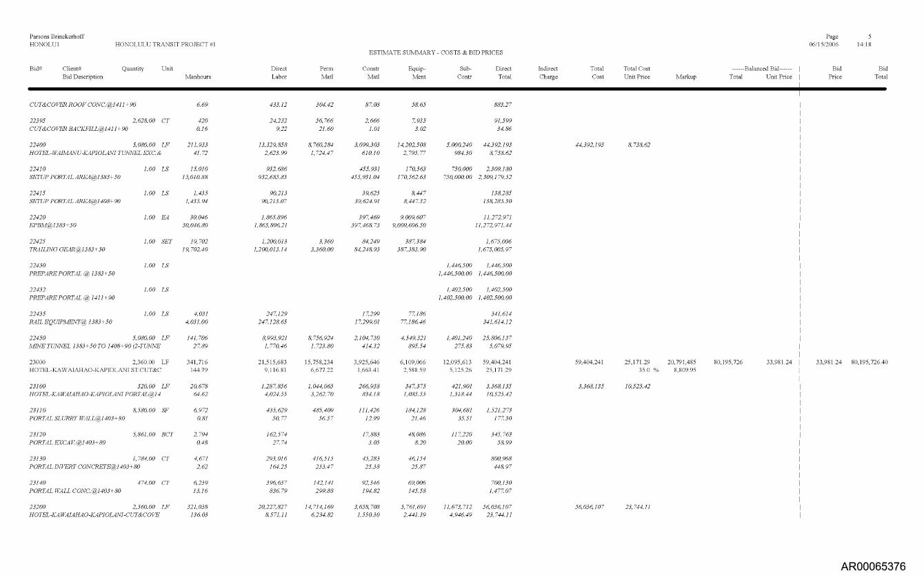
Parsons Brinckerhoff Page 5 HONOLU1 HONOLULU TRANSIT PROJECT #1 06/15/2006 14:18
ESTIMATE SUMMARY - COSTS & BID PRICES
Bid# Client# Quantity Unit Bid Description Manhours
Direct Labor
Perm Matl
Constr Matt
Equip- Ment
Sub- Direct Contr Total
Indirect Total Charge Cost
Total Cost Unit Price Markup
Balanced Bid Total Unit Price
Bid Price
Bid Total
CUT&COVER ROOF CONC.@I411+ 90
22395 2,628.00 CY CUT&COVER BACKFILL@I411+ 90
22400 5,080.00 LF HOTEL-WAIMANU-KAPIOLANI TUNNEL EXC.&
22410 1.00 LS SETUP PORTAL AREA@1 383+ 50
22415 1.00 LS SETUP PORTAL AREA@1408+ 90
22420 1.00 EA EPBM@1383+50
22425 1.00 SET TRAILING GEAR@1383+ 50
22430 1.00 LS PREPARE PORTAL @1383+50
22432 1.00 LS PREPARE PORTAL @1411+90
22435 1.00 LS RAIL EQUIPMENT@ 1383+50
22450 5,080.00 LF MINE TUNNEL 1383+50 TO 1408+90 (2-TUATNE
23000 2,360.00 LF HOTEL-KAWAIAHAO-KAPIOLANI ST.CUT&C
23100 320.00 LF HOTEL-KAWAIAHAO-KAPIOLANI PORTAL@I 4
23110 8,580.00 SF PORTAL SLURRY WALL@I403+80
23120 5,861.00 BCY PORTAL EXCAV.@I403+ 80
23130 1,784.00 CY PORTAL INVERT CONCRETE@I403+ 80
23140 474.00 CY PORTAL WALL CONC.@1403+ 80
23200 2,3 60.00 LF HOTEL-KAWAIAHAO-KAPIOLANI-CUT&COVE
6.69
420 0.16
211,933 41.72
15,010 15,010.88
1,435 1,435.94
30,046 30,046.80
19,702 19,702.40
4,031 4,031.00
141,706 27.89
341,716 144.79
20,678 64.62
6,972 0.81
2,794 0.48
4,671 2.62
6,239 13.16
321,038 136.03
433.12
24,232 9.22
13,329,858 2,623.99
932,686 932,685.85
90,213 90,213.07
1,865,896 1,865,896.21
1,200,013 1,200,013.14
247,129 247,128.65
8,993,921 1,770.46
21,515,683 9,116.81
1,287,856 4,024.55
435,629 50.77
162,574 27.74
293,016 164.25
396,637 836.79
20,227,827 8,571.11
304.42
56,766 21.60
8,760,284 1,724.47
3,360 3,3 60.00
8,756,924 1,723.80
15,758,234 6,677.22
1,044,065 3,2 62.70
485,409 56.57
416,515 233.47
142,141 299.88
14,714,1 69 6,234.82
87.08
2,666 1.01
3,099,303 610.10
455,931 455,931.04
39,625 39,624.91
397,469 397,46873
84,249 84,24893
17,299 17,299.01
2,104,730 414.32
3,925,646 1,663.41
266,938 834.18
111,426 12.99
17,883 3.05
45,283 25.38
92,346 194.82
3,658,708 1,550.30
58.65
7,935 3.02
14,202,508 2,795.77
170,563 170,562.63
8,447 8,44 7.32
9,009,607 9,009,606.50
387,384 387,383.90
77,186 77,186.46
4,549,321 895.54
6,109,066 2,588.59
347,375 1,085.55
184,128 21.46
48,086 820
46,154 25.87
69,006 145.58
5,761,691 2,441.39
883.27
91,599 34.86
5,000,240 44,392,193
984.30 8,738.62
750,000 2,309,180
750,000.00 2,309,1 79.52
138,285 138,285.30
11,272,971 11,2 72,971.44
1,675,006 1,675,005.97
1,446,500 1,446,500
1,446,500.00 1,446,500.00
1,402,500 1,402,500
1,402,500.00 1,402,500.00
341,614 341,614.12
1,401,240 25,806,137
275.83 5,079.95
12,095,613 59,404,241
5,125.26 25,171.29
421,901 3,368,135
1,318.44 10,525.42
304,681 1,521,2 73
35.51 177.30
117,220 345,763
20.00 5899
800,968 44897
700,130 1,477.07
11,673,712 56,03 6,107
4,946.49 23,744.11
44,392,193
59,404,241
3,368,135
56,03 6,107
8,738.62
25,171.29 35.0 %
10,525.42
23,744.11
20,791,485 8,809.95
80,195,726 33,981.24 33,981.24 80,195,726.40
AR00065376

Parsons Brinckerhoff Page 6 HONOLU1 HONOLULU TRANSIT PROJECT #1 06/15/2006 14:18
ESTIMATE SUMMARY - COSTS & BID PRICES
Bid# Client# Quantity Unit
Direct Perm Constr Equip- Sub- Direct Indirect Total Total Cost Balanced Bid Bid Bid Bid Description
Manhours
Labor Matl Matt Ment Contr Total Charge Cost Unit Price
Markup
Total Unit Price Price Total
23210 155,760.00 SF 106,287 6,707,802 6,846,348 1,822,025 3,256,774 5,170,592 23,803,542 CUT&COVER SLURRY WALL@I380+20-1403+8 0.68 43.06 43.95 11.70 20.91 33.20 152.82
23220 89,156.00 BCY 37,456 2,179,641 239,760 645,017 1,783,120 4,847,539 CUT&COVER EXCAV.@1380+20-1403+80 0.42 24.45 2.69 7.23 20.00 54.37
23225 472.00 E4 4,720,000 4,720,000 F&I TIEBACKS@ 1380+20-1403+80 10,000.00 10,000.00
23230 8,566.00 CY 25,836 1,610,000 2,045,246 190,108 258,529 4,103,884 CUT&COVER INVERT CONC.@1380+20-1403+ 3.02 187.95 238.76 22.19 30.18 479.09
23235 1,836.00 CY 13,708 854,517 386,707 127,191 146,125 1,514,540 CUT&COVER WALKWAY CONC.@1380+20-140 7.47 465.42 210.62 69.28 79.59 824.91
23240 6,556.00 CY 60,830 3,930,442 1,928,495 593,146 660,814 7,112,896 CUT&COVER WALL CONC.@1380+20-1403+80 9.28 599.52 294.16 90.47 100.80 1,084.94
23245 2,098.00 CY 20,529 1,330,144 534,101 253,466 238,748 2,356,460 CUT&COVER INTERIOR WALL CONC.@1380+2 9.79 634.01 254.58 120.81 113.80 1,123.19
23250 7,342.00 CY 50,920 3,300,136 2,235,032 398,345 452,485 6,385,999 CUT&COVER ROOF CONC.@1380+20-1403+ 80 6.94 449.49 304.42 54.26 61.63 869.79
23255 34,177.00 CY 5,468 315,145 738,239 34,666 103,198 1,191,247 CUT&COVER BACKFILL@I380+20-1403+ 80 0.16 9.22 21.60 1.01 3.02 34.86
Totals: 1,202,269 75,677,549 57,785,254 16,338,040 43,893,462 36,261,879 229,956,185 229,956,185 80,484,665 310,440,850 310,440,850.50
Code between Balanced Bid & Bid Price: U=Unbalanced, F=Frozen, C=Closing Biditem (item to absorb unbalancing differences).
[bracketed numbers represent adjusted quantities] ** in front of the Bid item indicates a Non-Additive item
Markup on Resource Costs 80,484,665
********* TOTAL JOB > 1,202,269 75,677,549 57,785,254 16,338,040 43,893,462 36,261,879 229,956,185 229,956,185 80,484,665 310,440,850 310,440,850.50
Spread Indirects On TOTAL COST Spread Markups On TOTAL COST Spread Addons&Bonds On TOTAL COST
Estimate Notes Bid Date: Owner: Engineering Firm:
Estimator in Charge:
Desired Bid (if specified) = 0.00 Sort: Hold Acct: N Subitem: Y NonAdd: N
AR00065377

Parsons Brinckerhoff Page 7 HONOLU1 HONOLULU TRANSIT PROJECT #1 06/15/2006 14:18
ESTIMATE SUMMARY - COSTS & BID PRICES
Bid# Client# Quantity Unit
Direct Perm Constr Equip- Sub- Direct Indirect Total Total Cost Balanced Bid Bid Bid Bid Description
Manhours
Labor Matl Matt Ment Contr Total Charge Cost Unit Price
Markup
Total Unit Price Price Total
Last Summary on 06/15/2006 at 10:09 AM. Last Spread on 06/15/2006 at 2:16 PM.
NOTE: Biditems that are subitems (have a parent biditem) are printed in italics.
AR00065378