tunnelling and underground space technology - geo …geogroup.mcgill.ca/research/journals/13-a study...
TRANSCRIPT
Tunnelling and Underground Space Technology 24 (2009) 716–722
Contents lists available at ScienceDirect
Tunnelling and Underground Space Technology
journal homepage: www.elsevier .com/ locate / tust
Technical note
A study on the effects of overlying soil strata on the stresses developingin a tunnel lining
M.A. Nunes, M.A. Meguid *
Department of Civil Engineering and Applied Mechanics, McGill University, 817 Sherbrooke Street West, Montreal, Quebec, Canada H3A 2K6
a r t i c l e i n f o a b s t r a c t
Article history:Received 7 April 2009Accepted 11 April 2009Available online 9 May 2009
Keywords:TunnellingExcavationOverlying strataLining stresses
0886-7798/$ - see front matter � 2009 Elsevier Ltd. Adoi:10.1016/j.tust.2009.04.002
* Corresponding author. Tel.: +1 514 398 1537; faxE-mail addresses: [email protected] (M.A
mcgill.ca (M.A. Meguid).
Shield tunnel lining in soft ground is usually designed based on empirical and analytical methods. Thesemethods are convenient and easy to use; however, they are based on simplifying assumptions related tosoil homogeneity around and above the excavated tunnel. The effects of overlying stiffer layers on thetunnelling induced settlement has been investigated by several researchers and was found to signifi-cantly influence ground movements. This study evaluates the effects of overlying stiff layers above a tun-nel excavated in soft ground on the stresses developing in the tunnel lining. Laboratory investigation isconducted to study how the presence of these layers influence bending stresses in a model tunnel con-structed in soft clay and overlain by a coarse sand layer located at different heights above the tunnel. Val-idation using the experimental results, elasto-plastic finite element analyses are then performed toexplain the role of the relative stiffness between the overlying layer and the soft soil deposit hostingthe tunnel. Depending on the thickness and location of the overlying stratum, the presence of a stiff layerabove the tunnel can have a significant impact on the stresses developing in the tunnel lining.
� 2009 Elsevier Ltd. All rights reserved.
1. Introduction
In engineering practice different methods are often used to cal-culate lining stresses, including empirical (e.g., Peck, 1969;Schmidt, 1974; Attwell, 1978; O’Reilly and New, 1982); analytical(e.g., Muir Wood, 1975; Einstein and Schwartz, 1979; Sagaseta,1987; Verruijt and Booker, 1996; Bobet, 2001) and numerical anal-yses (e.g., Mair et al., 1981; Swoboda et al., 1989; Lee and Rowe,1990; Addenbrooke and Potts, 2001). Among the above, empiricaland analytical methods are considered to be simple and convenienttools to calculate the stresses in a tunnel lining, however, thesemethods are usually based on simplifying assumptions related tothe soil homogeneity around the tunnel. Several physical modelshave been developed to study the ground response to tunnellingin homogenous soft ground including the trap door method (e.g.,Terzaghi, 1936; Vardoulakis et al., 1981; Tanaka and Sakai, 1993),a pre-installed tube with vinyl facing (e.g., Chambon and Corte,1994), a dissolvable polystyrene foam core (Sharma et al., 2001),or a miniature tunnel boring machine (Nomoto et al., 1999). Thesemethods are described in more detail elsewhere (Meguid et al.,2008).
Many fine-grained soil deposits are naturally layered as a resultof climatic cycles (Mitchell, 1976). The thickness of deposits
ll rights reserved.
: +1 514 398 7361.. Nunes), mohamed.meguid@
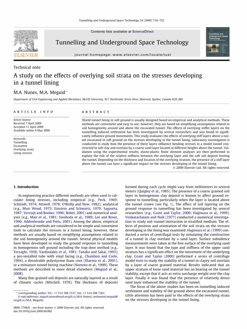
formed during each cycle might vary from millimeters to severalmeters (Quigley et al., 1985). The presence of a coarse grained soillayer in homogenous clay deposit is known to affect ground re-sponse to tunnelling, particularly when the layer is located abovethe tunnel crown (see Fig. 1). The effect of soil layering on theground response to tunnelling has been investigated by severalresearchers (e.g., Grant and Taylor, 2000; Hagiwara et al., 1999).Venkatachalam and Naik (1977) conducted a numerical investiga-tion to study soil–tunnel interaction in stratified medium. The ef-fects of position and orientation of the soil strata on the stressesdeveloping in the lining was examined. Hagiwara et al. (1999) con-ducted a series of centrifugal tests by simulating the constructionof a tunnel in clay overlain by a sand layer. Surface subsidencemeasurements were taken at the free surface of the overlying sandlayer. It was found that the type and stiffness of the upper sandstratum has a significant effect on the movement of the underlyingclay. Grant and Taylor (2000) performed a series of centrifugemodel tests to study the stability of a tunnel in clayey soil overlainby a layer of coarse grained material. Results indicated that anupper stratum of loose sand material has no bearing on the tunnelstability, except that it acts as extra surcharge weight over the claylayer. Finally it was found that the presence of relatively densesand layer enhanced the stability of the tunnel.
The focus of the above studies has been on tunnelling inducedsettlement and stability of the ground above the excavated tunnel.Little attention has been paid to the effects of the overlying strataon the stresses developing in the tunnel lining.
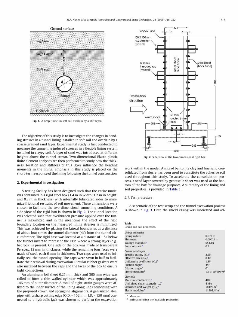
Fig. 2. Side view of the two-dimensional rigid box.
Table 1Lining and soil properties.
Lining propertiesLining radius 0.073 mThickness 0.00025 mYoung’s modulusa 65 GPaPoisson’s ratioa 0.3
Coarse sand layerSpecific gravity (Gs)a 2.65Effective size (D10)a 0.42Uniformity coefficient (Cu)a 1.88Friction anglea 35�Dilation anglea 0�Elastic modulusb 1.5 � 105 kN/m2
Clay mixMoisture content (wc)a 40%Undrained shear strength (cu)a 4 kPaSaturated unit weight (csat)a 18 kN/m3
Elastic modulusa 1150 kN/m2
a Measured.b Estimated using the available properties.
Tunnel
Ground surface
Bedrock
Stiff Layer
h
Soft soil
t
d
Soft soil
Fig. 1. A deep tunnel in soft soil overlain by a stiff layer.
M.A. Nunes, M.A. Meguid / Tunnelling and Underground Space Technology 24 (2009) 716–722 717
The objective of this study is to investigate the changes in bend-ing stresses in a tunnel lining installed in soft soil and overlain by acoarse grained sand layer. Experimental study is first conducted tomeasure the tunnelling induced stresses in a flexible lining systeminstalled in clayey soil. A layer of sand was introduced at differentheights above the tunnel crown. Two dimensional Elasto-plasticfinite element analyses are then performed to study how the thick-ness, location and stiffness of this layer influence the bendingmoments in the lining. Emphasis in this study is placed on theshort-term response of the lining following the tunnel construction.
2. Experimental investigation
A testing facility has been designed such that the entire modelwas contained in a rigid steel box (1.4 m in width; 1.2 m in height;and 0.3 m in thickness) with internally lubricated sides to mini-mize frictional restraint of soil movement. These dimensions werechosen to facilitate the two-dimensional tunnelling conditions. Aside view of the rigid box is shown in Fig. 2. The tunnel locationwas selected such that overburden pressure applied over the tun-nel is maximized and in the meantime the effect of the rigidboundary location on the measured lining stresses is minimized.This was achieved by placing the lateral boundaries at a distanceof about four times the tunnel diameter (4d) from the tunnel cir-cumference. The rigid base was located at a distance of 1.5d belowthe tunnel invert to represent the case where a strong layer (e.g.,bedrock) is present. One side of the box was made of transparentPerspex, 12 mm in thickness, while the remaining four faces weremade of steel, each 6 mm in thickness. Two caps were used to ini-tially seal the tunnel opening. The caps were sawn in half to facil-itate their removal during excavation. Circular rubber gaskets werealso installed between the caps and the faces of the box to ensuretight connections.
An aluminum foil sheet 0.25 mm thick and 305 mm wide wasrolled to form a thin-walled cylinder which was approximately146 mm of outer diameter. A total of eight strain gauges were af-fixed to the inner surface of the lining along lines coinciding withthe proposed crown and springline alignments. A galvanized steelpipe with a sharp cutting edge (O.D. = 152 mm, I.D. = 150 mm) con-nected to a hydraulic jack was chosen to perform the excavation
work within the model. A mix of bentonite clay and fine sand con-solidated from slurry has been used to constitute the cohesive soilused throughout this study. To accelerate the consolidation pro-cess, a sand layer covered by geotextile sheet was used at the bot-tom of the box for drainage purposes. A summary of the lining andsoil properties is provided in Table 1.
2.1. Test procedure
A schematic of the test setup and the tunnel excavation processis shown in Fig. 3. First, the shield casing was lubricated and ad-
Direction of Tunnel Advance
1
2
64
3
Steel track Shield casing
Hydraulic jack Prespex cap
Threaded rod Rigid box
1
2
3
4
5
6
4
5
5
Fig. 3. Schematic of the test setup.
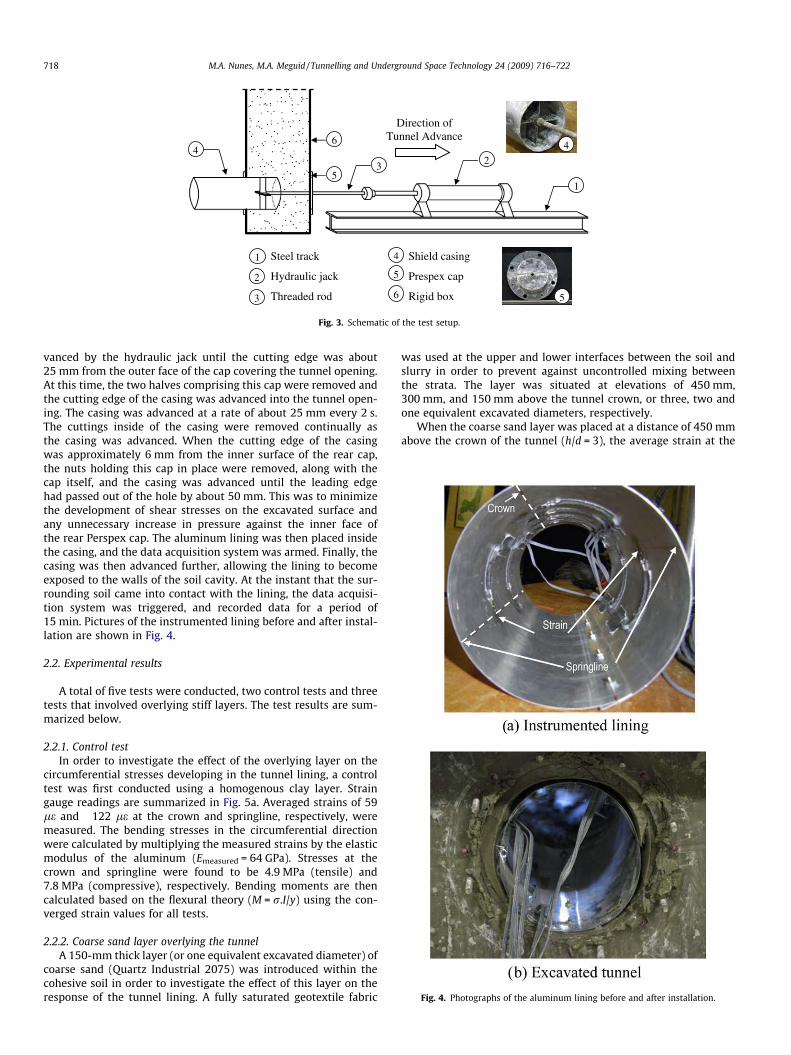
Fig. 4. Photographs of the aluminum lining before and after installation.
718 M.A. Nunes, M.A. Meguid / Tunnelling and Underground Space Technology 24 (2009) 716–722
vanced by the hydraulic jack until the cutting edge was about25 mm from the outer face of the cap covering the tunnel opening.At this time, the two halves comprising this cap were removed andthe cutting edge of the casing was advanced into the tunnel open-ing. The casing was advanced at a rate of about 25 mm every 2 s.The cuttings inside of the casing were removed continually asthe casing was advanced. When the cutting edge of the casingwas approximately 6 mm from the inner surface of the rear cap,the nuts holding this cap in place were removed, along with thecap itself, and the casing was advanced until the leading edgehad passed out of the hole by about 50 mm. This was to minimizethe development of shear stresses on the excavated surface andany unnecessary increase in pressure against the inner face ofthe rear Perspex cap. The aluminum lining was then placed insidethe casing, and the data acquisition system was armed. Finally, thecasing was then advanced further, allowing the lining to becomeexposed to the walls of the soil cavity. At the instant that the sur-rounding soil came into contact with the lining, the data acquisi-tion system was triggered, and recorded data for a period of15 min. Pictures of the instrumented lining before and after instal-lation are shown in Fig. 4.
2.2. Experimental results
A total of five tests were conducted, two control tests and threetests that involved overlying stiff layers. The test results are sum-marized below.
2.2.1. Control testIn order to investigate the effect of the overlying layer on the
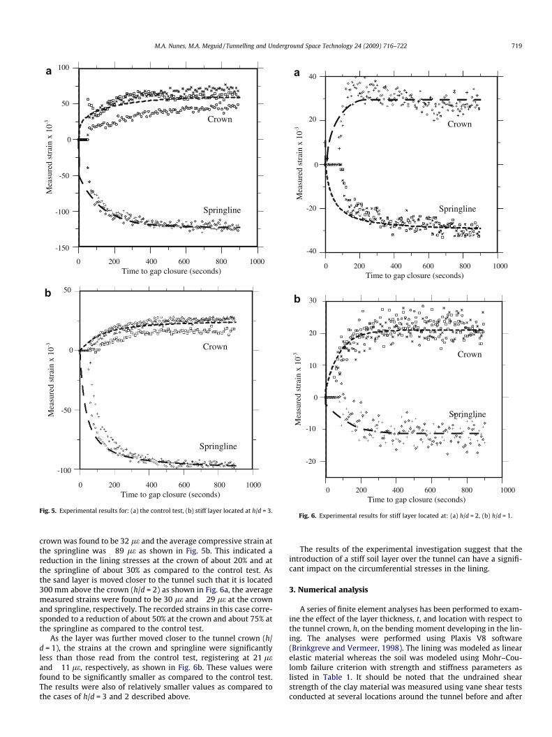
circumferential stresses developing in the tunnel lining, a controltest was first conducted using a homogenous clay layer. Straingauge readings are summarized in Fig. 5a. Averaged strains of 59le and �122 le at the crown and springline, respectively, weremeasured. The bending stresses in the circumferential directionwere calculated by multiplying the measured strains by the elasticmodulus of the aluminum (Emeasured = 64 GPa). Stresses at thecrown and springline were found to be 4.9 MPa (tensile) and7.8 MPa (compressive), respectively. Bending moments are thencalculated based on the flexural theory (M = r.I/y) using the con-verged strain values for all tests.
2.2.2. Coarse sand layer overlying the tunnelA 150-mm thick layer (or one equivalent excavated diameter) of
coarse sand (Quartz Industrial 2075) was introduced within thecohesive soil in order to investigate the effect of this layer on theresponse of the tunnel lining. A fully saturated geotextile fabric
was used at the upper and lower interfaces between the soil andslurry in order to prevent against uncontrolled mixing betweenthe strata. The layer was situated at elevations of 450 mm,300 mm, and 150 mm above the tunnel crown, or three, two andone equivalent excavated diameters, respectively.
When the coarse sand layer was placed at a distance of 450 mmabove the crown of the tunnel (h/d = 3), the average strain at the
100
50
0
-50
-100
-150
Mea
sure
d st
rain
x 1
0-3
0 200 400 600 800 1000 Time to gap closure (seconds)
Springline
Crown
Springline
Crown
50
0
-50
-100
0 200 400 600 800 1000 Time to gap closure (seconds)
Mea
sure
d st
rain
x 1
0-3
a
b
Fig. 5. Experimental results for: (a) the control test, (b) stiff layer located at h/d = 3.
Springline
Crown
30
20
10
0
-10
-20
0 200 400 600 800 1000 Time to gap closure (seconds)
Mea
sure
d st
rain
x 1
0-3
0 200 400 600 800 1000 Time to gap closure (seconds)
40
20
0
-20
-40
Mea
sure
d st
rain
x 1
0-3
Springline
Crown
a
b
Fig. 6. Experimental results for stiff layer located at: (a) h/d = 2, (b) h/d = 1.
M.A. Nunes, M.A. Meguid / Tunnelling and Underground Space Technology 24 (2009) 716–722 719
crown was found to be 32 le and the average compressive strain atthe springline was �89 le as shown in Fig. 5b. This indicated areduction in the lining stresses at the crown of about 20% and atthe springline of about 30% as compared to the control test. Asthe sand layer is moved closer to the tunnel such that it is located300 mm above the crown (h/d = 2) as shown in Fig. 6a, the averagemeasured strains were found to be 30 le and �29 le at the crownand springline, respectively. The recorded strains in this case corre-sponded to a reduction of about 50% at the crown and about 75% atthe springline as compared to the control test.
As the layer was further moved closer to the tunnel crown (h/d = 1), the strains at the crown and springline were significantlyless than those read from the control test, registering at 21 leand �11 le, respectively, as shown in Fig. 6b. These values werefound to be significantly smaller as compared to the control test.The results were also of relatively smaller values as compared tothe cases of h/d = 3 and 2 described above.
The results of the experimental investigation suggest that theintroduction of a stiff soil layer over the tunnel can have a signifi-cant impact on the circumferential stresses in the lining.
3. Numerical analysis
A series of finite element analyses has been performed to exam-ine the effect of the layer thickness, t, and location with respect tothe tunnel crown, h, on the bending moment developing in the lin-ing. The analyses were performed using Plaxis V8 software(Brinkgreve and Vermeer, 1998). The lining was modeled as linearelastic material whereas the soil was modeled using Mohr–Cou-lomb failure criterion with strength and stiffness parameters aslisted in Table 1. It should be noted that the undrained shearstrength of the clay material was measured using vane shear testsconducted at several locations around the tunnel before and after
720 M.A. Nunes, M.A. Meguid / Tunnelling and Underground Space Technology 24 (2009) 716–722
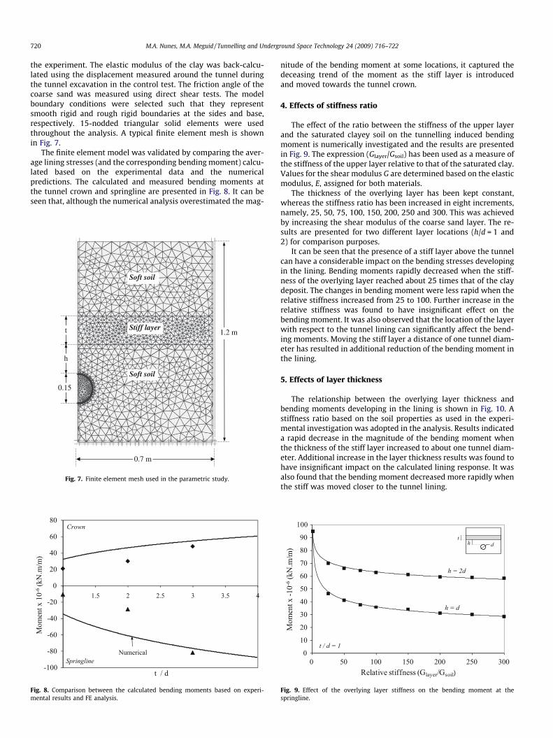
the experiment. The elastic modulus of the clay was back-calcu-lated using the displacement measured around the tunnel duringthe tunnel excavation in the control test. The friction angle of thecoarse sand was measured using direct shear tests. The modelboundary conditions were selected such that they representsmooth rigid and rough rigid boundaries at the sides and base,respectively. 15-nodded triangular solid elements were usedthroughout the analysis. A typical finite element mesh is shownin Fig. 7.
The finite element model was validated by comparing the aver-age lining stresses (and the corresponding bending moment) calcu-lated based on the experimental data and the numericalpredictions. The calculated and measured bending moments atthe tunnel crown and springline are presented in Fig. 8. It can beseen that, although the numerical analysis overestimated the mag-
Soft soil
0.7 m
Stiff layer
Soft soil
0.15
t
h
1.2 m
Fig. 7. Finite element mesh used in the parametric study.
-100
-80
-60
-40
-20
0
20
40
60
80
1 1.5 2 2.5 3 3.5 4
Mom
ent x
10-6
(kN
.m/m
)
t / d
Crown
Springline Numerical
Fig. 8. Comparison between the calculated bending moments based on experi-mental results and FE analysis.
nitude of the bending moment at some locations, it captured thedeceasing trend of the moment as the stiff layer is introducedand moved towards the tunnel crown.
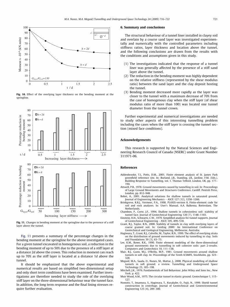
4. Effects of stiffness ratio
The effect of the ratio between the stiffness of the upper layerand the saturated clayey soil on the tunnelling induced bendingmoment is numerically investigated and the results are presentedin Fig. 9. The expression (Glayer/Gsoil) has been used as a measure ofthe stiffness of the upper layer relative to that of the saturated clay.Values for the shear modulus G are determined based on the elasticmodulus, E, assigned for both materials.
The thickness of the overlying layer has been kept constant,whereas the stiffness ratio has been increased in eight increments,namely, 25, 50, 75, 100, 150, 200, 250 and 300. This was achievedby increasing the shear modulus of the coarse sand layer. The re-sults are presented for two different layer locations (h/d = 1 and2) for comparison purposes.
It can be seen that the presence of a stiff layer above the tunnelcan have a considerable impact on the bending stresses developingin the lining. Bending moments rapidly decreased when the stiff-ness of the overlying layer reached about 25 times that of the claydeposit. The changes in bending moment were less rapid when therelative stiffness increased from 25 to 100. Further increase in therelative stiffness was found to have insignificant effect on thebending moment. It was also observed that the location of the layerwith respect to the tunnel lining can significantly affect the bend-ing moments. Moving the stiff layer a distance of one tunnel diam-eter has resulted in additional reduction of the bending moment inthe lining.
5. Effects of layer thickness
The relationship between the overlying layer thickness andbending moments developing in the lining is shown in Fig. 10. Astiffness ratio based on the soil properties as used in the experi-mental investigation was adopted in the analysis. Results indicateda rapid decrease in the magnitude of the bending moment whenthe thickness of the stiff layer increased to about one tunnel diam-eter. Additional increase in the layer thickness results was found tohave insignificant impact on the calculated lining response. It wasalso found that the bending moment decreased more rapidly whenthe stiff was moved closer to the tunnel lining.
0
10
20
30
40
50
60
70
80
90
100
0 50 100 150 200 250 300
Mom
ent x
-10-6
(kN
.m/m
)
Relative stiffness (Glayer/Gsoil)
t / d = 1
h = 2d
h = d
h dt
Fig. 9. Effect of the overlying layer stiffness on the bending moment at thespringline.
0
10
20
30
40
50
60
70
80
90
100
0 0.5 1 1.5 2 2.5
Mom
ent x
-10
-6(k
N.m
/m)
t / d
Glayer/Gsoil=130
h = 2d
h = d
h dt
Fig. 10. Effect of the overlying layer thickness on the bending moment at thespringline.
0
10
20
30
40
50
60
70
80
Perc
enta
ge r
educ
tion
in
bend
ing
mom
ent
Increasing layer thickness
h = 2d
h = d
t / d 0.5 1 1.5 2 2.5
0
10
20
30
40
50
60
70
80
Perc
enta
ge r
educ
tion
in b
endi
ng
mom
ent
Increasing layer stiffness
h = 2d
h = d
Glayer/Gsoil 50 100 150 200 300
Fig. 11. Changes in bending moment at the springline due to the presence of a stifflayer above the tunnel.
M.A. Nunes, M.A. Meguid / Tunnelling and Underground Space Technology 24 (2009) 716–722 721
Fig. 11 presents a summary of the percentage changes in thebending moment at the springline for the above investigated cases.For a given tunnel excavated in homogenous soil, a reduction in thebending moment of up to 50% due to the presence of a stiff layer ata distance 2d above the crown. This reduction in moment can reachup to 70% as the stiff layer is located at a distance 1d above thetunnel.
It should be emphasized that the above experimental andnumerical results are based on simplified two-dimensional setupand only short term conditions have been examined. Further inves-tigations are therefore needed to study the role of the overlyingstiff layer on the three-dimensional behaviour near the tunnel face.In addition, the long term response and the final lining stresses re-quire further evaluation.
6. Summary and conclusions
The structural behaviour of a tunnel liner installed in clayey soiland overlain by a course sand layer was investigated experimen-tally and numerically with the controlled parameters includingstiffness ratios, layer thickness and location above the tunnel,and the following conclusions are drawn from the results withthe conditions and assumptions given in this study.
(1) The investigations indicated that the response of a tunnelliner was generally affected by the presence of a stiff sandlayer above the tunnel.
(2) The reduction in the bending moment was highly dependenton the relative stiffness (represented by the shear modulusratio) between the sand layer and the clay deposit hostingthe tunnel.
(3) Bending moment decreased more rapidly as the layer wascloser to the tunnel with a maximum decrease of 70% fromthe case of homogenous clay when the stiff layer (of shearmodulus ratio of more than 100) was located one tunneldiameter from the tunnel crown.
Further experimental and numerical investigations are neededto study other aspects of this interesting tunnelling problemincluding the cases when the stiff layer is crossing the tunnel sec-tion (mixed face conditions).
Acknowledgements
This research is supported by the Natural Sciences and Engi-neering Research Council of Canada (NSERC) under Grant Number311971-06.
References
Addenbrooke, T.I., Potts, D.M., 2001. Finite element analysis of St. James Parkgreenfield reference site. In: Burland, J.B., Standing, J.R., Jardine, F.M. (Eds.),Building Response to Tunnelling, vol. 1. Thomas Telford, London, UK, pp. 177–194.
Attwell, P.B., 1978. Ground movements caused by tunnelling in soil. In: Proceedingsof Large Ground Movements and Structures Conference, Cardiff. Pentish Press,London, pp. 812–948.
Bobet, A., 2001. Analytical solutions for shallow tunnels in saturated ground.Journal of Engineering Mechanics – ASCE 127 (12), 1258–1266.
Brinkgreve, R.B.J., Vermeer, P.A., 1998. PLAXIS-version 8, Finite-element code forsoil and rock analyses. In: User’s Manual, A.A. Balkema, Rotterdam, TheNetherlands.
Chambon, P., Corte, J.F., 1994. Shallow tunnels in cohesionless soil: stability oftunnel face. Journal of Geotechnical Engineering 120 (7), 1148–1165.
Einstein, H.H., Schwartz, C.W., 1979. Simplified analysis for tunnel supports. Journalof Geotechnical Engineering - ASCE 105, 499–518.
Grant, R.J., Taylor, R.N., 2000. Stability of tunnels in clay with overlying layers ofcoarse grained soil. In: GeoEng 2000: An International Conference onGeotechnical and Geological Engineering, Melbourne, Australia.
Hagiwara, T., Grant, R.J., Calvello, M., Taylor, R.N., 1999. The effect of overlying strataon the distribution of ground movements induced by tunnelling in clay. Soilsand Foundations 39 (3), 63–73.
Lee, K.M., Rowe, R.K., 1990. Finite element modeling of the three-dimensionalground movements due to tunnelling in soft cohesive soils: part 2-results.Computers and Geotechnics 10, 111–138.
Mair, R.J., Gunn, M.J., O’Reilly, M.P., 1981. Ground movements around shallowtunnels in soft clay. In: Proceedings of the Tenth ICSMFE, Stockholm, pp. 323–328.
Meguid, M.A., Saada, O., Nunes, M., Mattar, J., 2008. Physical modelling of shallowtunnels in soft ground: a review. Tunnelling and Underground SpaceTechnology 23, 185–198.
Mitchell, J.K., 1976. Fundamentals of Soil Behaviour. John Wiley and Sons Inc., NewYork. p. 422.
Muir Wood, A.M., 1975. The circular tunnel in elastic ground. Geotechnique 1, 115–127.
Nomoto, T., Imamura, S., Hagiwara, T., Kusakabe, O., Fujii, N., 1999. Shield tunnelconstruction in centrifuge. Journal of Geotechnical and GeoenvironmentalEngineering 125 (4), 289–300.

722 M.A. Nunes, M.A. Meguid / Tunnelling and Underground Space Technology 24 (2009) 716–722
O’Reilly, M.P., New, B.M., 1982. Settlements above tunnels in the UK – theirmagnitude and prediction. In: Proceedings of Tunnelling’ 82, IMM, London, pp.173–181.
Peck, R.B., 1969, Deep excavations and tunneling in soft ground. In: Proceedings ofthe Seventh International Conference on Soil Mechanics and FoundationEngineering, Mexico City, pp. 225–290.
Quigley, R.M., Sethi, A.J., Boonsinsuk, P., Sheeran, D.E., Yong, R.N., 1985. Geologiccontrol on soil composition and properties, Lake Ojibway clay plain, Matagami,Quebec. Canadian Geotechnical Journal 22 (4), 491–500.
Sagaseta, C., 1987. Analysis of undrained soil deformation due to ground loss.Geotechnique 37 (3), 301–320.
Schmidt, B., 1974. Prediction of settlements due to tunneling in soil: three casehistories. In: Proceedings of the Second Rapid Excavation and TunnelingConference, San Francisco, vol. 2, pp. 1179–1199.
Sharma, J.S., Bolton, M.D., Boyle, R.E., 2001. A new technique for simulation oftunnel excavation in a centrifuge. Geotechnical Testing Journal 24 (4), 343–349.
Swoboda, G., Mertz, W., Schmid, A., 1989. Three dimensional numerical models tosimulate tunnel excavation. In: Proceedings of NUMLOG III. Elsevier SciencePublishers Ltd., London, pp. 36–548.
Tanaka, T., Sakai, T., 1993. Progressive failure and scale effect of trapdoor problemwith granular materials. Soils and Foundations 33 (1), 11–22.
Terzaghi, K., 1936. Stress distribution in dry and in saturated sand above a yieldingtrap-door. In: Proceedings of the International Conference on Soil Mechanics,Cambridge, MA, pp. 307–311.
Vardoulakis, I., Graf, B., Gudehus, G., 1981. Trap-door problem with dry sand: astatical approach based upon model test kinematics. International Journal forNumerical and Analytical Methods in Geomechanics 5, 57–78.
Venkatachalam, G., Naik, A.V., 1977. Interaction in tunnels in stratified media. In:Proceedings of the International Symposium on Soil Structure Interaction,University of Roorkee, India, pp. 33–38.
Verruijt, A., Booker, J.R., 1996. Surface settlements due to deformation of a tunnel inan elastic half plane. Geotechnique 46 (4), 753–756.