tunable if filter using thin-film bstvaractorsmy.ece.ucsb.edu/york/yorklab/publications/biobib/212 -...
TRANSCRIPT

Tunable IF Filter using Thin-Film BST Varactors
Glenn Sanderson', Albert H. Cardona', Thomas C. Watson', David Chase2,Manas Roy3, Joseph M. Paricka3, and Robert A. York4
'Agile Materials and Technologies, Inc., Goleta, CA 931 17 USA2Vareda Inc., Goleta, CA 931 17 USA
3Rockwell Collins Inc., Cedar Rapids, IA 52498-0001 USA4University of California, Santa Barbara, CA 93106 USA
Abstract This paper describes the design andcharacterization of a lumped-element tunable IF filter using thin-film barium strontium titanate (BST) varactors. The filter wasdesigned to operate from 30-88MHz in three separate switch-selectable bands with a 0-12V DC control voltage. A relativelyconstant insertion loss of <5dB was obtained over the desiredtuning range. The circuit was also characterized overtemperature from -40°C to +80°C, showing relatively littlechange in insertion loss over temperature, but a slight reductionin tuning range at elevated temperatures.Index Terms - Tunable filters, tunable dielectrics, varactors,
BST.
I. INTRODUCTION
HIGH-PERMITTIVITY thin-film dielectrics exhibit a strongfield-dependence in the dielectric constant that can beexploited for voltage-variable capacitors in RF circuits. Thin-film Barium Strontium Titanate (BST) and Bizmuth ZincNiobate (BZN) are examples of materials that have beeninvestigated for RF applications [1]-[6]. Unlike conventionaldiode varactors, these devices have no forward conductionregion, and consequently can be used in applications requiringlarge RF voltage swings over the full range of DC tuningvoltage. Using circuit techniques [9], varactors with high RFpower handling and high linearity can be designed withrelatively good Q-factors (>50) and tunabilities in excess of2:1 in the microwave frequency range.Much of the applications work involving dielectric varactors
has centered on low-cost phase shifters [3]. The use of thesevaractors in tunable filters has received comparably littleattention to date, although some promising results have beenreported [4,6]. This paper describes the implementation of asimple BST-based tunable band-pass filter covering the 30-88MHz band. We will describe the design of the filter andpresent RF measurements over a wide temperature range from-40C to +80C.
II. DESCRIPTION OF THE CIRCUIT
The motivation for this work was to create a compact,wideband IF filter covering the 30-88MHz band. Keyspecifications for this filter included a rejection of >15dB at±6% from the center frequency, lowest possible insertion loss,<0.05dB passband variation over ±25kHz in the 30-50MHz
range, and <0.05dB passband variation over ±150kHz in the50-88MHz range. The filter was designed from the start withthe intention of using dielectric varactors for improved powerhandling and linearity, and assumed the availability ofvaractors with a tunability of 2.5:1 and a Q-factor of >60 inthe desired frequency range. Ultimately a 38dBm powerhandling capacity was desired, but this initial prototype effortdid not specifically address this requirement.A number of circuit techniques exist for the implementation
of tunable band-pass filters [7,8]. In this work, a relativelysimple inductively-coupled resonator filter was implementedas shown in fig. 1. With the assumed varactor properties, thedesired specifications could be achieved using a 2-resonatordesign, with each varactor implemented as a bank of threeswitch-selectable varactors, enabling coverage of the full 30-88MHz band in three separate sub-bands. Lumped-elementinductors were used in this design, with RF input and outputsignals coupled though tapping points on the resonatorinductances. This standard technique [8] allows for arelatively constant insertion loss over frequency, and allowsthe resonator impedance to be optimized for the desired filtercharacteristics while simultaneously allowing for a goodinput/output match.
Fig. 1. Basic circuit topology for the tunable bandpass filterdescribed in this work.
A detailed schematic of the actual circuit implementationincluding the bias network is shown in fig. 2. The 6.7~fHbridge inductance is implemented with three separate series-connected inductances to maintain a high self-resonantfrequency. The resonator inductors were air-core coils madefrom #18 AWG wire with Q-factors of approximately 300.The varactor bank for each resonator consisted of fournominally identical 40pF BST varactors operating with a DCcontrol voltage from 0-12 V. Manual SPST switches wereused in the experimental prototype to connect the varactors,but these will ultimately be implemented with MEMS devicesor PIN diodes. The DC control is applied to the varactors
1-4244-0688-9/07/$20.00 C 2007 IEEE 679Authorized licensed use limited to: Univ of Calif Santa Barbara. Downloaded on April 29, 2009 at 16:50 from IEEE Xplore. Restrictions apply.
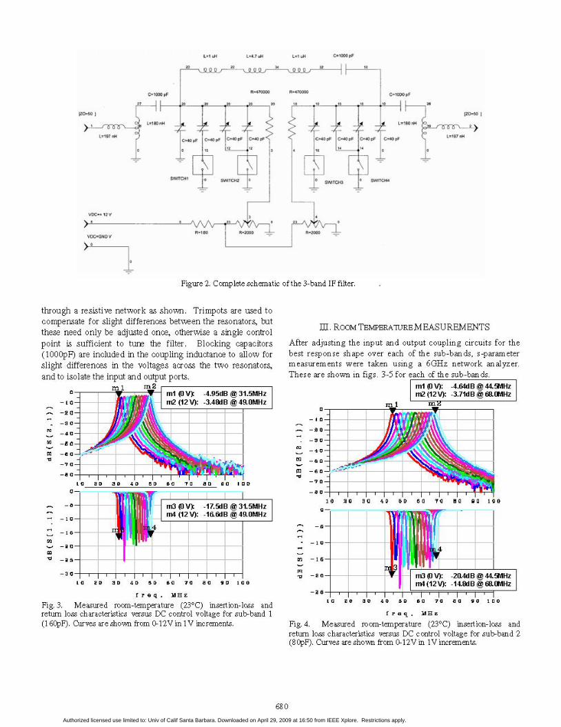
Figure 2. Complete schematic of the 3-band IF filter.
through a resistive network as shown. Trimpots are used tocompensate for slight differences between the resonators, butthese need only be adjusted once, otherwise a single controlpoint is sufficient to tune the filter. Blocking capacitors(lOOOpF) are included in the coupling inductance to allow forslight differences in the voltages across the two resonators,and to isolate the input and output ports.
0 2 0 30 40 50 sa 70 80 90 1 a
-5. m3 (0 V): -17.5dB @ 31.5MHzm4 (12 V): -16.6dB @49.0MHz
210 1
U 2
-30-
10 20 3D 40 50 60 70 aa 90 100
f req, MHz
Fig. 3. Measured room-temperature (23°C) insertion-loss andreturn loss characteristics versus DC control voltage for sub-band 1(16OpF). Curves are shown from 0-12V in 1V increments.
III. ROOM TEMPERATURE MEASUREMENTS
After adjusting the input and output coupling circuits for thebest response shape over each of the sub-bands, s-parametermeasurements were taken using a 6GHz network analyzer.These are shown in figs. 3-5 for each ofthe sub-bands.
ml (0 V): -4.64dB @ 44.5MHzm2 (12 V): -3.71dB @ 68.0MHz
, mrI M;z
10 20 30 40 50 B0 70 BO 90 100
1 0-
1 5-
-2 0-
II10 20 3D 4
m3 (0 V): -20.4dB @ 44.5MHzm4 (12 V): -14.8dB 68.0MHz
40 5D 60 70 0 9o0 1 OD
f req, MHz
Fig. 4. Measured room-temperature (23°C) insertion-loss andreturn loss characteristics versus DC control voltage for sub-band 2(8OpF). Curves are shown from 0-12V in IV increments.
680
n
F]
cpim of
r`LL---d0 L.rlSO OiiH
-1
1) C#O g
M 0
Hms mm. .m. F
4 .~ IN 04
In
CM0 PF C*49 p C-40
Authorized licensed use limited to: Univ of Calif Santa Barbara. Downloaded on April 29, 2009 at 16:50 from IEEE Xplore. Restrictions apply.
-2 0
4 0
-6 0
a 0
ml (O V): -5.1dB@ 60.0m2 (12 V): -4.2dB @ 90.0
1 a 20 30 40 5 D 60
m
10 20 30 4D 50 60 70 80
)MHz%RA U-
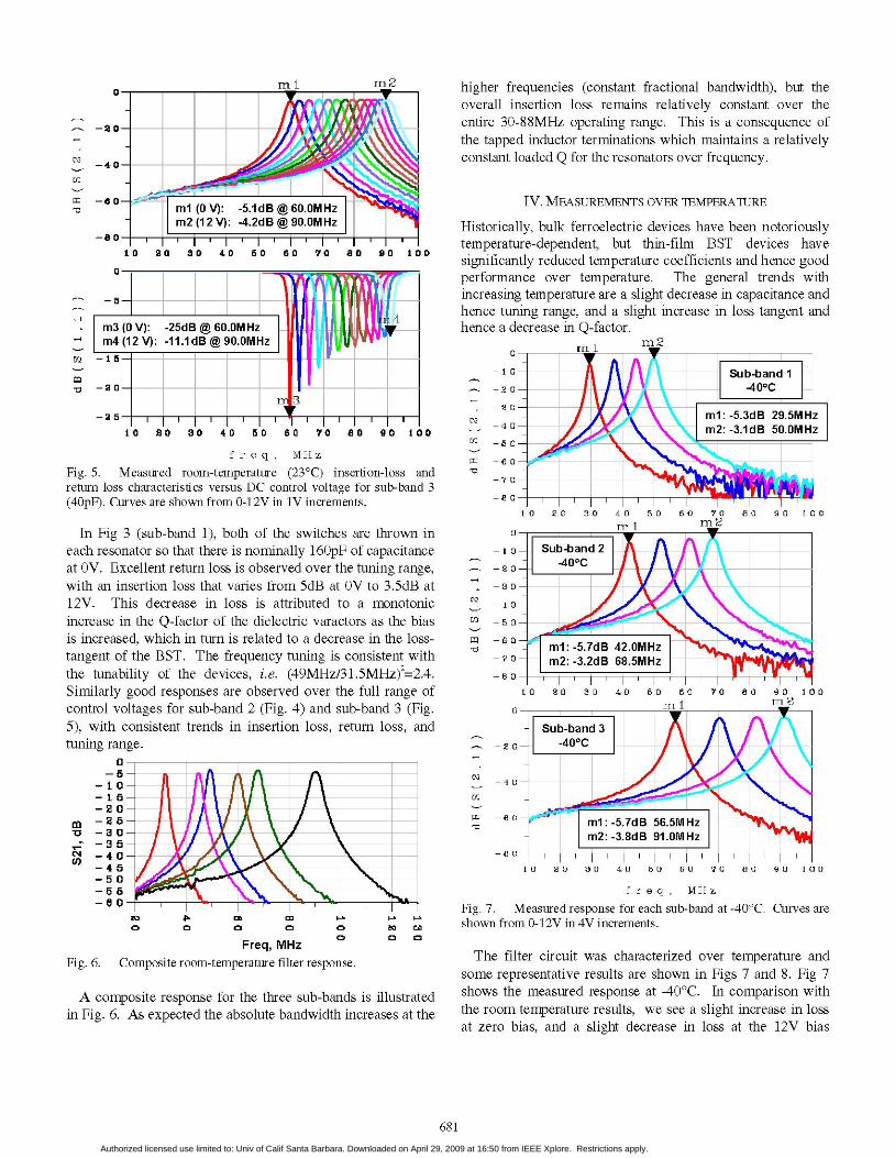
higher frequencies (constant fractional bandwidth), but theoverall insertion loss remains relatively constant over theentire 30-88MHz operating range. This is a consequence ofthe tapped inductor terminations which maintains a relativelyconstant loaded Q for the resonators over frequency.
IV. MEASUREMENTS OVER TEMPERATUREvHnz Historically, bulk ferroelectric devices have been notoriously
70 T1 100Tl temperature-dependent, but thin-film BST devices have7 a E o 0o 0o o significantly reduced temperature coefficients and hence good
performance over temperature. The general trends withincreasing temperature are a slight decrease in capacitance andhence tuning range, and a slight increase in loss tangent andhence a decrease in Q-factor.
90 100
freq, MHz
Fig. 5. Measured room-temperature (23°C) insertion-loss andreturn loss characteristics versus DC control voltage for sub-band 3(4OpF). Curves are shown from 0-12V in IV increments.
In Fig 3 (sub-band 1), both of the switches are thrown ineach resonator so that there is nominally 160pF of capacitanceat OV. Excellent return loss is observed over the tuning range,with an insertion loss that varies from 5dB at OV to 3.5dB at12V. This decrease in loss is attributed to a monotonicincrease in the Q-factor of the dielectric varactors as the biasis increased, which in turn is related to a decrease in the loss-tangent of the BST. The frequency tuning is consistent withthe tunability of the devices, i.e. (49MHz/31.5MHz)2=2.4.Similarly good responses are observed over the full range ofcontrol voltages for sub-band 2 (Fig. 4) and sub-band 3 (Fig.5), with consistent trends in insertion loss, return loss, andtuning range.
0-
-51 0 -
1 5 -
-2 0-
-2 5-3 O
3 5-4 0--4 5-5 0-5 5--6 0-
cO n n eo c
Freq, MHzFig. 6. Composite room-temperature filter response.
Dato
A composite response for the three sub-bands is illustratedin Fig. 6. As expected the absolute bandwidth increases at the
m
-CDi
I0 20 30 40 50 60 70 80 90 100Tr" I mr2
- I 0-
-2 0-
-3 0-
-4 0-
-5 0-
- -
-7 0-
au r
10 20 30 40 50 60 70 a0 90 10
0- . I_I _
Sub-band 32 0 -400C
-40-
-6 0 - >- - H1 0ml: -5.7dB 56.5MHzm2: -3.8dB 91.0MHz
-e Ii
10 20 30 4D 50 6a 70 80 90 100
fre q, MHz
Fig. 7. Measured response for each sub-band at -40°C. Curves are
shown from 0-12V in 4V increments.
The filter circuit was characterized over temperature andsome representative results are shown in Figs 7 and 8. Fig 7shows the measured response at -40°C. In comparison withthe room temperature results, we see a slight increase in lossat zero bias, and a slight decrease in loss at the 12V bias
681
ml: -5.7dB 42.0MHzm2: -3.2dB 68.5MHz
m
la
0
Il
v
Authorized licensed use limited to: Univ of Calif Santa Barbara. Downloaded on April 29, 2009 at 16:50 from IEEE Xplore. Restrictions apply.

points. In addition, the overall tuning range has broadeneddue to the increased tunability of the device of lowertemperatures.
In contrast, Fig 8 shows the measured response at +80°C,where in comparison with the room temperature results thereis reduction in overall tuning range because of the reducedtunability of the device of higher temperature. Thiscompression in tunability over temperature must clearly beaccounted for in future design iterations in order to insurecomplete coverage of the desired sub-bands.
1 m2
10 20 30 40 50 60 70 BO so i00
- I 0
-2 0
3 0
-4 0
u; _5 0
mn -s6O
-7 0
- aO
I0 20 30 40 5D 70 80 90
m X m E
1 0-
-2 0-
-3 0-
-4 0-
-5 0-
6 0-
-7 0-
-8 0-
I 4lIlI1 0 20:RO a3 4 0 50a 6 7 0 sa In
I 0 D
1 0 a
freq MHz
Fig. 8. Measured response for each sub-band at +80'C. Curvesare shown from 0-12V in 4V increments.
VII. Conclusion
Dielectric varactors show promise for the realization of low-cost tunable or reconfigurable RF circuits, especially inapplications requiring high RF voltage swings. This paper has
demonstrated a high performance IF filter using BSTvaractors, covering 30-88MHz with <5dB insertion loss andexcellent performance over temperature. Future work will bedirected towards electronic control of the switched capacitornetwork, and the use of stacked capacitors for improved powerhandling and linearity.
ACKNOWLEDGEMENT
The authors wish to acknowledge the assistance of MikeFink and Dr. Chris Elsass at Agile Materials and TechnologiesInc..
REFERENCES
[1] R. A. York, A. Nagra, E. Erker, T. Taylor, P. Periaswamy, J.Speck, S. Streiffer, 0. Auciello, "Microwave integrated circuitsusing thin-film BST", Proc. 12th Intl Symp. on Applications ofFerroelectrics (ISAF), vol 1, July 2000, pp. 195-200
[2] A. Tombak, J.-P. Maria, F.T.-Ayguavives, Jin Zhang, G. T.Stauf, A. I. Kingon, A. Mortazawi, "Tunable barium strontiumtitanate thin film capacitors for RF and microwave applications"IEEE Microwave and Wireless Components Letters, vol. 12,Jan. 2002, pp. 3-5
[3] B. Acikel, T.R. Taylor, P.J. Hansen, J.S. Speck, R.A. York, "Anew high performance phase shifter using BaxSrl-xTiO3 thinfilms", IEEE Microwave Wireless Comp. Lett., vol. 12, July2002, pp. 237-239
[4] A. Tombak, J.-P. Maria, F.T.-Ayguavives, Jin Zhang, G. T.Stauf, A. I. Kingon, A. Mortazawi, "Voltage-controlled RFfilters employing thin-film barium-strontium-titanate tunablecapacitors" IEEE Trans. Microwave Theory Tech., Vol. 51,Feb. 2003 pp. 462 - 467
[5] A. Vorobiev, P. Rundqvist, K. Khamchane, and S. Gevorgian,"Silicon substrate integrated high Q-factor parallel-plateferroelectric varactors for microwave/millimeterwaveapplications", Appl. Phys. Lett. 83, 3144 (2003)
[6] L.-Y. Chen, R. Forse, D. Chase, and R. York, "Analog tunablematching network using integrated thin-film BST capacitors",IEEE MTT-S Intl. Microwave Symp. Digest, 2004 ,Volume:1,June 2004 pp261 - 264
[7] K. Jeganathan, "Design of Simple Tunable/Switchable BandpassFilter" Applied Microwave & Wireless, March 2000, pp.32 - 40
[8] V. Koren, "Design of a constant insertion loss variablefrequency LC band-pass filter" Applied Microwave & Wireless,vol. 12, September 2000
[9] J-S. Fu, X.A. Zhu, D-Y. Chen, J.D. Phillips, and A.Mortazawi,"A Linearity Improvement Technique for Thin-film bariumstrontium titanate Capacitors". EEE MTT-S Int. MicrowaveSymposium (IMS 2006), June 2006. see also United StatesPatent 6,674,321 "Circuit configuration for DC-biasedcapacitors", issued Jan 4, 2004.
682
Vy
Sub-band 3
+800C
ml: -5.0dB 62.0MHzm2: -4.9dB 89.0MHz
T
l] L
Authorized licensed use limited to: Univ of Calif Santa Barbara. Downloaded on April 29, 2009 at 16:50 from IEEE Xplore. Restrictions apply.