tt-r110 tt-r110ex owner's manual - yamaha - · pdf file ·...
TRANSCRIPT

5B6-28199-10
TT-R110EX
OWNER’S MANUAL
LIT-11626-21-48

EAU10041
U5B610E0.book Page 1 Thursday, July 12, 2007 1:41 PM

INTRODUCTIONEAU41730
Congratulations on your purchase of the Yamaha TT-R110EX. This model is the result of Yamaha’s vast experience in theproduction of fine sporting, touring, and pacesetting racing machines. It represents the high degree of craftsmanship andreliability that have made Yamaha a leader in these fields.This manual will give you an understanding of the operation, inspection, and basic maintenance of this motorcycle. If youhave any questions concerning the operation or maintenance of your motorcycle, please consult a Yamaha dealer.The design and manufacture of this Yamaha motorcycle fully comply with the emissions standards for clean air applicable atthe date of manufacture. Yamaha has met these standards without reducing the performance or economy of operation of themotorcycle. To maintain these high standards, it is important that you and your Yamaha dealer pay close attention to therecommended maintenance schedules and operating instructions contained within this manual.AN IMPORTANT SAFETY MESSAGE:
� READ THIS MANUAL, THE “PARENTS, YOUNGSTERS AND OFF-HIGHWAY MOTORCYCLES” BOOKLET, ANDTHE “TIPS AND PRACTICE GUIDE FOR THE OFF HIGHWAY MOTORCYCLIST” BOOKLET CAREFULLY ANDCOMPLETELY BEFORE OPERATING THIS MOTORCYCLE. MAKE SURE YOU UNDERSTAND ALL INSTRUC-TIONS.
� PAY CLOSE ATTENTION TO THE WARNING AND CAUTION LABELS ON THE MOTORCYCLE.� NEVER OPERATE A MOTORCYCLE WITHOUT PROPER TRAINING OR INSTRUCTION.� WEIGHT OF THE RIDER SHOULD NOT EXCEED 60 kg (132 lb).
AN IMPORTANT NOTE TO PARENTS:This motorcycle is not a toy. Before you let your child ride this motorcycle, you should understand the instructions and warn-ings in this Owner’s Manual. Then be sure your child understands and will follow them. Also read the “PARENTS, YOUNG-STERS AND OFF-HIGHWAY MOTORCYCLES” and the “TIPS AND PRACTICE GUIDE FOR THE OFF HIGHWAYMOTORCYCLIST” booklets supplied with this motorcycle when new or available from your Yamaha dealer. Children differin skills, physical abilities, and judgment. Some children may not be able to operate a motorcycle safely. Parents should su-pervise their child’s use of the motorcycle at all times. Parents should permit continued use only if they determine that thechild has the ability to operate the motorcycle safely.
U5B610E0.book Page 1 Thursday, July 12, 2007 1:41 PM
INTRODUCTIONMOTORCYCLES ARE SINGLE TRACK VEHICLES. THEIR SAFE USE AND OPERATION ARE DEPENDENT UPONTHE USE OF PROPER RIDING TECHNIQUES AS WELL AS THE EXPERTISE OF THE OPERATOR. EVERY OPERA-TOR SHOULD KNOW THE FOLLOWING REQUIREMENTS BEFORE RIDING THIS MOTORCYCLE.HE OR SHE SHOULD:
� OBTAIN THOROUGH INSTRUCTIONS FROM A COMPETENT SOURCE ON ALL ASPECTS OF MOTORCYCLEOPERATION.
� OBSERVE THE WARNINGS AND MAINTENANCE REQUIREMENTS IN THE OWNER’S MANUAL.� OBTAIN QUALIFIED TRAINING IN SAFE AND PROPER RIDING TECHNIQUES.� OBTAIN PROFESSIONAL TECHNICAL SERVICE AS INDICATED BY THE OWNER’S MANUAL AND/OR WHEN
MADE NECESSARY BY MECHANICAL CONDITIONS.
U5B610E0.book Page 2 Thursday, July 12, 2007 1:41 PM
IMPORTANT MANUAL INFORMATIONEAU39300
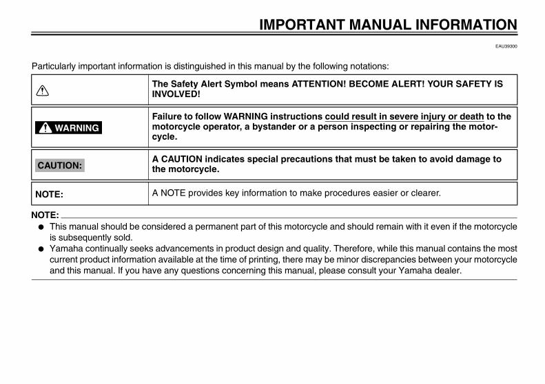
Particularly important information is distinguished in this manual by the following notations:
NOTE:� This manual should be considered a permanent part of this motorcycle and should remain with it even if the motorcycle
is subsequently sold.� Yamaha continually seeks advancements in product design and quality. Therefore, while this manual contains the most
current product information available at the time of printing, there may be minor discrepancies between your motorcycleand this manual. If you have any questions concerning this manual, please consult your Yamaha dealer.
The Safety Alert Symbol means ATTENTION! BECOME ALERT! YOUR SAFETY IS INVOLVED!
Failure to follow WARNING instructions could result in severe injury or death to the motorcycle operator, a bystander or a person inspecting or repairing the motor-cycle.
A CAUTION indicates special precautions that must be taken to avoid damage to the motorcycle.
A NOTE provides key information to make procedures easier or clearer.
WARNING
CAUTION:
NOTE:
U5B610E0.book Page 1 Thursday, July 12, 2007 1:41 PM
IMPORTANT MANUAL INFORMATION
WARNINGEWA14460
PLEASE READ THIS MANUAL, THE “TIPS AND PRACTICE GUIDE FOR THE OFF HIGHWAY MOTORCYCLIST” ANDTHE “PARENTS, YOUNGSTERS AND OFF-HIGHWAY MOTORCYCLES” BOOKLETS CAREFULLY AND COMPLETE-LY BEFORE OPERATING OR ALLOWING YOUR CHILD TO OPERATE THIS MOTORCYCLE. DO NOT ATTEMPT TOOPERATE THIS MOTORCYCLE UNTIL YOU HAVE ATTAINED ADEQUATE KNOWLEDGE OF ITS CONTROLS ANDOPERATING FEATURES AND UNTIL YOU HAVE BEEN TRAINED IN SAFE AND PROPER RIDING TECHNIQUES.REGULAR INSPECTIONS AND CAREFUL MAINTENANCE, ALONG WITH GOOD RIDING SKILLS, WILL ENSURETHAT YOU SAFELY ENJOY THE CAPABILITIES AND THE RELIABILITY OF THIS MOTORCYCLE.
WARNINGEWA14350
THIS MOTORCYCLE IS DESIGNED AND MANUFACTURED FOR OFF-ROAD USE ONLY. IT IS ILLEGAL TO OPER-ATE THIS MOTORCYCLE ON ANY PUBLIC STREET, ROAD OR HIGHWAY. SUCH USE IS PROHIBITED BY LAW.THIS MOTORCYCLE COMPLIES WITH ALMOST ALL STATE OFF-HIGHWAY NOISE LEVEL AND SPARK ARRESTERLAWS AND REGULATIONS. PLEASE CHECK YOUR LOCAL RIDING LAWS AND REGULATIONS BEFORE OPERAT-ING THIS MOTORCYCLE.
*Product and specifications are subject to change without notice.
U5B610E0.book Page 2 Thursday, July 12, 2007 1:41 PM

IMPORTANT MANUAL INFORMATION
EAU10192
TT-R110EXOWNER’S MANUAL
©2007 by Yamaha Motor Corporation, U.S.A.1st edition, June 2007
All rights reserved.Any reprinting or unauthorized use without the written permission of Yamaha Motor Corporation, U.S.A.
is expressly prohibited.Printed in Japan.
P/N LIT-11626-21-48
AFFIX DEALER
LABEL HERE
U5B610E0.book Page 3 Thursday, July 12, 2007 1:41 PM

TABLE OF CONTENTSSAFETY INFORMATION ..................1-1
Safe riding ......................................1-1Location of important labels ............1-4
DESCRIPTION ..................................2-1Left view ..........................................2-1Right view ........................................2-2Controls and instruments.................2-3
INSTRUMENT AND CONTROL FUNCTIONS .......................................3-1
Main switch .....................................3-1Handlebar switches ........................3-1Shift pedal .......................................3-2Brake lever .....................................3-2Brake pedal ....................................3-2Fuel tank cap ..................................3-3Fuel .................................................3-3Fuel tank breather hose ..................3-4Fuel cock ........................................3-4Starter (choke) lever .......................3-5Kickstarter .......................................3-6Seat ................................................3-6Sidestand ........................................3-7Starting circuit cut-off system .........3-7
PRE-OPERATION CHECKS ..............4-1Pre-operation check list ..................4-2
OPERATION AND IMPORTANT RIDING POINTS................................. 5-1
Starting and warming up a cold engine ......................................... 5-1
Starting a warm engine .................. 5-2Shifting ........................................... 5-2Engine break-in .............................. 5-3Parking ........................................... 5-4
PERIODIC MAINTENANCE AND MINOR REPAIR ................................. 6-1
PERIODIC MAINTENANCE ........... 6-1Owner’s tool kit ............................... 6-2Periodic maintenance chart for
the emission control system ....... 6-3General maintenance and
lubrication chart .......................... 6-4Removing and installing panels ..... 6-6Checking the spark plug ................. 6-7Engine oil ....................................... 6-8Cleaning the air filter element ...... 6-10Cleaning the spark arrester .......... 6-12Adjusting the carburetor ............... 6-13Adjusting the engine idling
speed ........................................ 6-13Checking the throttle cable
free play .................................... 6-14Valve clearance ............................ 6-14Tires ............................................. 6-15Spoke wheels ............................... 6-16
Accessories and replacement parts ......................................... 6-16
Adjusting the clutch free play ....... 6-17Adjusting the brake lever free
play ........................................... 6-17Adjusting the brake pedal free
play ........................................... 6-18Checking the shift pedal .............. 6-19Checking the front and
rear brake shoes ...................... 6-19Drive chain slack .......................... 6-20Cleaning and lubricating
the drive chain .......................... 6-21Checking and lubricating
the cables ................................. 6-22Checking and lubricating
the throttle grip and cable ......... 6-22Checking and lubricating
the brake lever .......................... 6-23Checking and lubricating
the brake pedal ......................... 6-23Checking and lubricating
the sidestand ............................ 6-23Lubricating the swingarm
pivots ........................................ 6-24Checking the front fork ................. 6-24Checking the steering .................. 6-25Checking the wheel bearings ....... 6-25Battery ......................................... 6-26Replacing the fuse ....................... 6-27Supporting the motorcycle ........... 6-28
U5B610E0.book Page 1 Thursday, July 12, 2007 1:41 PM

TABLE OF CONTENTSFront wheel ...................................6-28Rear wheel ...................................6-30Troubleshooting ............................6-31Troubleshooting chart ...................6-32
MOTORCYCLE CARE AND STORAGE ..........................................7-1
Matte color caution .........................7-1Care ................................................7-1Storage ...........................................7-3
SPECIFICATIONS .............................8-1
CONSUMER INFORMATION.............9-1Identification numbers ....................9-1Motorcycle noise regulation ............9-3YAMAHA MOTOR CORPORATION,
U.S.A. OFF-ROAD MOTORCYCLE LIMITED WARRANTY ...............................9-4
YAMAHA EXTENDED SERVICE (Y.E.S.) .......................................9-6
U5B610E0.book Page 2 Thursday, July 12, 2007 1:41 PM

1-1
1
SAFETY INFORMATION EAU39313
Safe riding� Always make pre-operation
checks. Careful checks may helpprevent an accident.
� This motorcycle is designed for off-road use only, therefore, it is illegalto operate it on public streets,roads, or highways, even a dirt orgravel one. Off-road use on publiclands may be illegal. Please checklocal regulations before riding.
� This motorcycle is designed to car-ry the operator only. No passen-gers.
� Many accidents involve inexperi-enced operators.• Make sure that the operator is
qualified and that you only lendyour motorcycle to other quali-fied operators.
• Know your skills and limits.Staying within your limits mayhelp you to avoid an accident.
� Many accidents have been causedby error of the motorcycle opera-tor. A typical error made by the op-erator is veering wide on a turndue to EXCESSIVE SPEED or un-
dercornering (insufficient lean an-gle for the speed). Never travelfaster than warranted by condi-tions.
� Ride cautiously in unfamiliar ar-eas. You may encounter hiddenobstacles that could cause an ac-cident.
� The posture of the operator is im-portant for proper control. The op-erator should keep both hands onthe handlebar and both feet on theoperator footrests during operationto maintain control of the motor-cycle.
� Never ride under the influence ofalcohol or other drugs.
� Be sure the transmission is in neu-tral before starting the engine.
Protective apparelThe majority of fatalities from motor-cycle accidents are the result of headinjuries. The use of a safety helmet isthe single most critical factor in the pre-vention or reduction of head injuries.
� Always wear an approved helmet.
� Wear a face shield or goggles.Wind in your unprotected eyescould contribute to an impairmentof vision that could delay seeing ahazard.
� The use of a jacket, heavy boots,trousers, gloves, etc., is effective inpreventing or reducing abrasionsor lacerations.
� Never wear loose-fitting clothes,otherwise they could catch on thecontrol levers, footrests, or wheelsand cause injury or an accident.
� Never touch the engine or exhaustsystem during or after operation.They become very hot and cancause burns. Always wear protec-tive clothing that covers your legs,ankles, and feet.
ModificationsModifications made to this motorcyclenot approved by Yamaha, or the re-moval of original equipment, may ren-der the motorcycle unsafe for use andmay cause severe personal injury.Modifications may also make yourmotorcycle illegal to use.
U5B610E0.book Page 1 Thursday, July 12, 2007 1:41 PM

SAFETY INFORMATION
1-2
1
Loading and accessoriesAdding accessories to your motorcyclecan adversely affect stability and han-dling if the weight distribution of themotorcycle is changed. To avoid thepossibility of an accident, use extremecaution when adding accessories toyour motorcycle. Use extra care whenriding a motorcycle that has added ac-cessories. Here are some generalguidelines to follow if adding accesso-ries to your motorcycle:Loading
� The weight of the operator mustnot exceed 60 kg (132 lb).
� Accessory weight should be keptas low and close to the motorcycleas possible. Make sure to distrib-ute the weight as evenly as possi-ble on both sides of the motorcycleto minimize imbalance or instabili-ty.
� Shifting weights can create a sud-den imbalance. Make sure that ac-cessories are securely attached tothe motorcycle before riding.Check accessory mounts fre-quently.
� Never attach any large or heavyitems to the handlebar, front fork,or front fender.
AccessoriesGenuine Yamaha accessories havebeen specifically designed for use onthis motorcycle. Since Yamaha cannottest all other accessories that may beavailable, you must personally be re-sponsible for the proper selection, in-stallation and use of non-Yamahaaccessories. Use extreme cautionwhen selecting and installing any ac-cessories.Keep these guidelines in mind formounting accessories in addition tothose provided under “Loading”.
� Never install accessories or thatwould impair the performance ofyour motorcycle. Carefully inspectthe accessory before using it tomake sure that it does not in anyway reduce ground clearance orcornering clearance, limit suspen-sion travel, steering travel or con-trol operation.• Accessories fitted to the handle-
bar or the front fork area cancreate instability due to improper
weight distribution or aerody-namic changes. If accessoriesare added to the handlebar orfront fork area, they must be aslightweight as possible andshould be kept to a minimum.
• Bulky or large accessories mayseriously affect the stability ofthe motorcycle due to aerody-namic effects. Wind may at-tempt to lift the motorcycle, orthe motorcycle may become un-stable in cross winds.
• Certain accessories can dis-place the operator from his orher normal riding position. Thisimproper position limits the free-dom of movement of the opera-tor and may limit control ability,therefore, such accessories arenot recommended.
� Use caution when adding electri-cal accessories. If electrical acces-sories exceed the capacity of themotorcycle’s electrical system, anelectric failure could result, whichcould cause a dangerous loss ofengine power.
U5B610E0.book Page 2 Thursday, July 12, 2007 1:41 PM

SAFETY INFORMATION
1-3
1
Gasoline and exhaust gas� GASOLINE IS HIGHLY FLAMMA-
BLE:• Always turn the engine off when
refueling.• Take care not to spill any gaso-
line on the engine or exhaustpipe(s)/muffler(s) when refuel-ing.
• Never refuel while smoking or inthe vicinity of an open flame.
� Never start the engine or let it runfor any length of time in a closedarea. The exhaust fumes are poi-sonous and may cause loss ofconsciousness and death within ashort time. Always operate yourmotorcycle in an area that has ad-equate ventilation.
� Always turn the engine off beforeleaving the motorcycle unattendedand remove the key from the mainswitch. When parking the motor-cycle, note the following:• The engine and exhaust pipe(s)/
muffler(s) may be hot, therefore,park the motorcycle in a place
where pedestrians or childrenare not likely to touch these hotareas.
• Do not park the motorcycle on aslope or soft ground, otherwise itmay fall over.
• Do not park the motorcycle neara flammable source (e.g., a ker-osene heater, or near an openflame), otherwise it could catchfire.
� When transporting the motorcyclein another vehicle, make sure thatit is kept upright and that the fuelcock(s) are turned to “ON” or“RES” (for vacuum type)/“OFF”(for manual type). If the motorcycleshould lean over, gasoline mayleak out of the carburetor or fueltank.
� If you should swallow any gaso-line, inhale a lot of gasoline vapor,or allow gasoline to get into youreyes, see your doctor immediately.If any gasoline spills on your skinor clothing, immediately wash theaffected area with soap and waterand change your clothes.
U5B610E0.book Page 3 Thursday, July 12, 2007 1:41 PM

SAFETY INFORMATION
1-4
1
EAU10381
Location of important labels Please read the following important labels carefully before operating this vehicle.
3
1
WARNINGBEFORE YOU OPERATE THIS VEHICLE, READ THE OWNER’SMANUAL AND ALL LABELS.NEVER CARRY A PASSENGER. You increase your risk of losingcontrol if you carry a passenger.NEVER OPERATE THIS VEHICLE ON PUBLIC ROADS. You cancollide with another vehicle if you operate this vehicle on a public road.ALWAYS WEAR AN APPROVED MOTORCYCLE HELMET,eye protection, and protective clothing.
3PT-2118K-A0
2
Cold tire normal pressure should be set asfollows.FRONT : 100 kPa, {1.00 kgf/cm2}, 15 psiREAR : 100 kPa, {1.00 kgf/cm2}, 15 psi
3RV-21668-A0
TIRE INFOMATION
21 3
U5B610E0.book Page 4 Thursday, July 12, 2007 1:41 PM

DESCRIPTION
2-1
2
EAU10410
Left view
678
1 2 3 4
51. Fuel cock (page 3-4)2. Starter (choke) lever (page 3-5)3. Fuse (page 6-27)4. Battery (page 6-26)5. Clutch adjusting screw (page 6-17)6. Engine oil drain bolt (page 6-8)7. Shift pedal (page 3-2)8. Throttle stop screw (page 6-13)
U5B610E0.book Page 1 Thursday, July 12, 2007 1:41 PM
DESCRIPTION
2-2
2
EAU10420
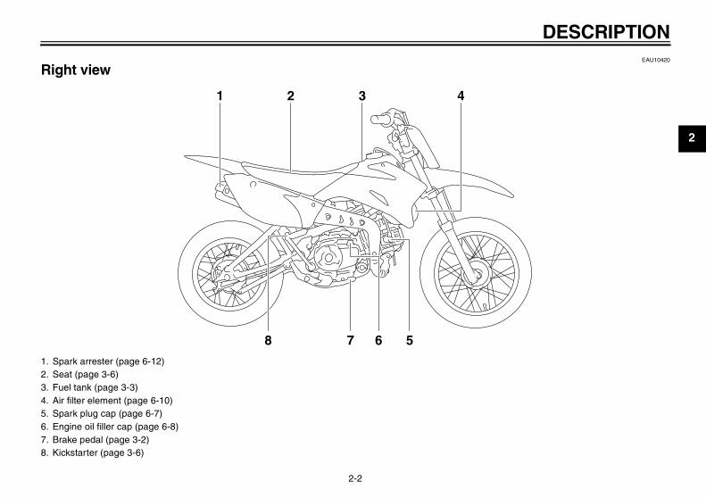
Right view
1 2 3 4
8 57 6
1. Spark arrester (page 6-12)2. Seat (page 3-6)3. Fuel tank (page 3-3)4. Air filter element (page 6-10)5. Spark plug cap (page 6-7)6. Engine oil filler cap (page 6-8)7. Brake pedal (page 3-2)8. Kickstarter (page 3-6)
U5B610E0.book Page 2 Thursday, July 12, 2007 1:41 PM
DESCRIPTION
2-3
2
EAU10430
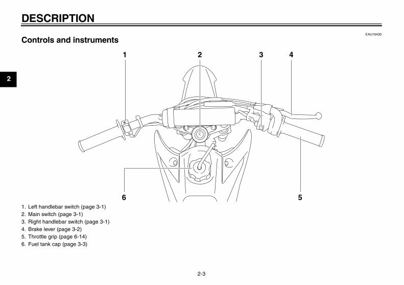
Controls and instruments
1 2 3 4
561. Left handlebar switch (page 3-1)2. Main switch (page 3-1)3. Right handlebar switch (page 3-1)4. Brake lever (page 3-2)5. Throttle grip (page 6-14)6. Fuel tank cap (page 3-3)
U5B610E0.book Page 3 Thursday, July 12, 2007 1:41 PM

INSTRUMENT AND CONTROL FUNCTIONS
3-1
3
EAU40340
Main switch
The main switch controls the ignitionsystem. The main switch positions aredescribed below.
EAU10630
ONAll electrical systems are supplied withpower, and the engine can be started.The key cannot be removed.
EAU10660
OFFAll electrical systems are off. The keycan be removed.
EAU12347
Handlebar switches
Left
Right
EAU12660
Engine stop switch “ / ” Set this switch to “ ” before startingthe engine. Set this switch to “ ” tostop the engine in case of an emergen-cy, such as when the vehicle overturnsor when the throttle cable is stuck.
EAU12710
Start switch “ ” Push this switch to crank the enginewith the starter.
CAUTION:ECA10050
See page 5-1 for starting instruc-tions prior to starting the engine.
1. Engine stop switch “ / ”
1. Start switch “ ”1
U5B610E0.book Page 1 Thursday, July 12, 2007 1:41 PM
INSTRUMENT AND CONTROL FUNCTIONS
3-2
3
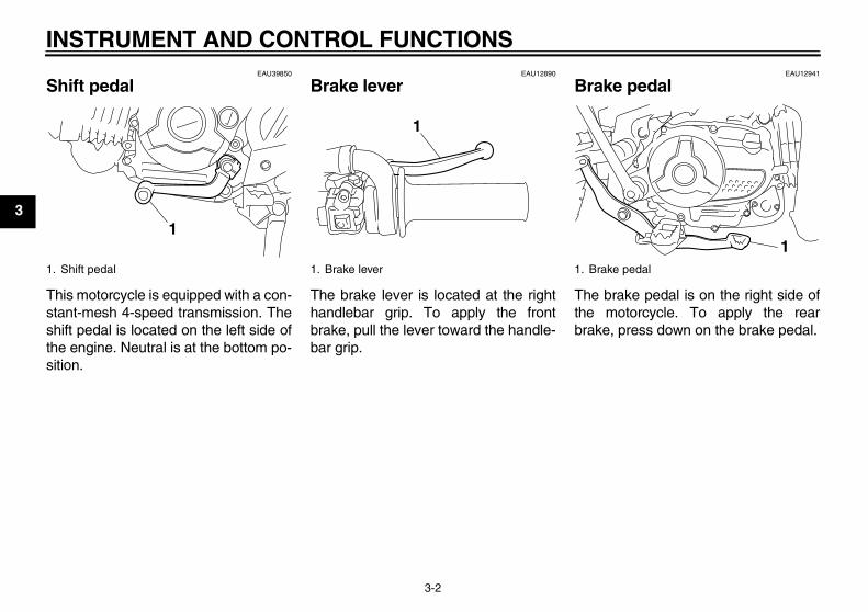
EAU39850
Shift pedal
This motorcycle is equipped with a con-stant-mesh 4-speed transmission. Theshift pedal is located on the left side ofthe engine. Neutral is at the bottom po-sition.
EAU12890
Brake lever
The brake lever is located at the righthandlebar grip. To apply the frontbrake, pull the lever toward the handle-bar grip.
EAU12941
Brake pedal
The brake pedal is on the right side ofthe motorcycle. To apply the rearbrake, press down on the brake pedal.
1. Shift pedal
1
1. Brake lever
1
1. Brake pedal
1
U5B610E0.book Page 2 Thursday, July 12, 2007 1:41 PM
INSTRUMENT AND CONTROL FUNCTIONS
3-3
3
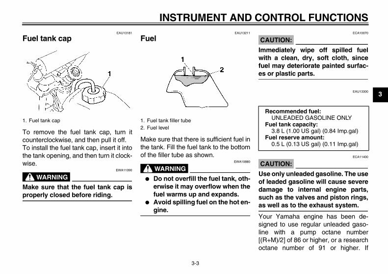
EAU13181
Fuel tank cap
To remove the fuel tank cap, turn itcounterclockwise, and then pull it off.To install the fuel tank cap, insert it intothe tank opening, and then turn it clock-wise.
WARNINGEWA11090
Make sure that the fuel tank cap isproperly closed before riding.
EAU13211
Fuel
Make sure that there is sufficient fuel inthe tank. Fill the fuel tank to the bottomof the filler tube as shown.
WARNINGEWA10880
� Do not overfill the fuel tank, oth-erwise it may overflow when thefuel warms up and expands.
� Avoid spilling fuel on the hot en-gine.
CAUTION:ECA10070
Immediately wipe off spilled fuelwith a clean, dry, soft cloth, sincefuel may deteriorate painted surfac-es or plastic parts.
EAU13300
CAUTION:ECA11400
Use only unleaded gasoline. The useof leaded gasoline will cause severedamage to internal engine parts,such as the valves and piston rings,as well as to the exhaust system.
Your Yamaha engine has been de-signed to use regular unleaded gaso-line with a pump octane number[(R+M)/2] of 86 or higher, or a researchoctane number of 91 or higher. If
1. Fuel tank cap 1. Fuel tank filler tube2. Fuel level
Recommended fuel:UNLEADED GASOLINE ONLY
Fuel tank capacity:3.8 L (1.00 US gal) (0.84 Imp.gal)
Fuel reserve amount:0.5 L (0.13 US gal) (0.11 Imp.gal)
U5B610E0.book Page 3 Thursday, July 12, 2007 1:41 PM
INSTRUMENT AND CONTROL FUNCTIONS
3-4
3
knocking (or pinging) occurs, use agasoline of a different brand or premi-um unleaded fuel. Use of unleaded fuelwill extend spark plug life and reducemaintenance costs.GasoholThere are two types of gasohol: gaso-hol containing ethanol and that contain-ing methanol. Gasohol containingethanol can be used if the ethanol con-tent does not exceed 10%. Gasoholcontaining methanol is not recom-mended by Yamaha because it cancause damage to the fuel system or ve-hicle performance problems.
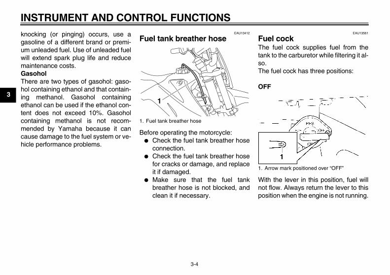
EAU13412
Fuel tank breather hose
Before operating the motorcycle:� Check the fuel tank breather hose
connection.� Check the fuel tank breather hose
for cracks or damage, and replaceit if damaged.
� Make sure that the fuel tankbreather hose is not blocked, andclean it if necessary.
EAU13561
Fuel cock The fuel cock supplies fuel from thetank to the carburetor while filtering it al-so.The fuel cock has three positions:
OFF
With the lever in this position, fuel willnot flow. Always return the lever to thisposition when the engine is not running.
1. Fuel tank breather hose
1
1. Arrow mark positioned over “OFF”
U5B610E0.book Page 4 Thursday, July 12, 2007 1:41 PM

INSTRUMENT AND CONTROL FUNCTIONS
3-5
3
ON
With the lever in this position, fuel flowsto the carburetor. Normal riding is donewith the lever in this position.
RES
This indicates reserve. If you run out offuel while riding, move the lever to thisposition. Fill the tank at the first oppor-tunity. Be sure to set the lever back to“ON” after refueling!
EAU13590
Starter (choke) lever “ ”
Starting a cold engine requires a richerair-fuel mixture, which is supplied bythe starter (choke).Move the lever in direction (a) to turn onthe starter (choke).Move the lever in direction (b) to turn offthe starter (choke).
1. Arrow mark positioned over “ON”
1. Arrow mark positioned over “RES”
1. Starter (choke) lever “ ”
U5B610E0.book Page 5 Thursday, July 12, 2007 1:41 PM

INSTRUMENT AND CONTROL FUNCTIONS
3-6
3
EAU37650
Kickstarter
If the engine fails to start by pushing thestart switch, try to start it by using thekickstarter. To start the engine, fold outthe kickstarter lever, move it down light-ly with your foot until the gears engage,and then push it down smoothly butforcefully.
EAU13960
Seat
To remove the seatRemove the bolts, and then pull theseat off.
To install the seat1. Insert the projections on the front
of the seat into the seat holders asshown.
2. Place the seat in the original posi-tion, and then tighten the bolts.
NOTE:Make sure that the seat is properly se-cured before riding.
1. Kickstarter lever
1
1. Bolt
1
1. Projection2. Seat holder
1
2
U5B610E0.book Page 6 Thursday, July 12, 2007 1:41 PM
INSTRUMENT AND CONTROL FUNCTIONS
3-7
3
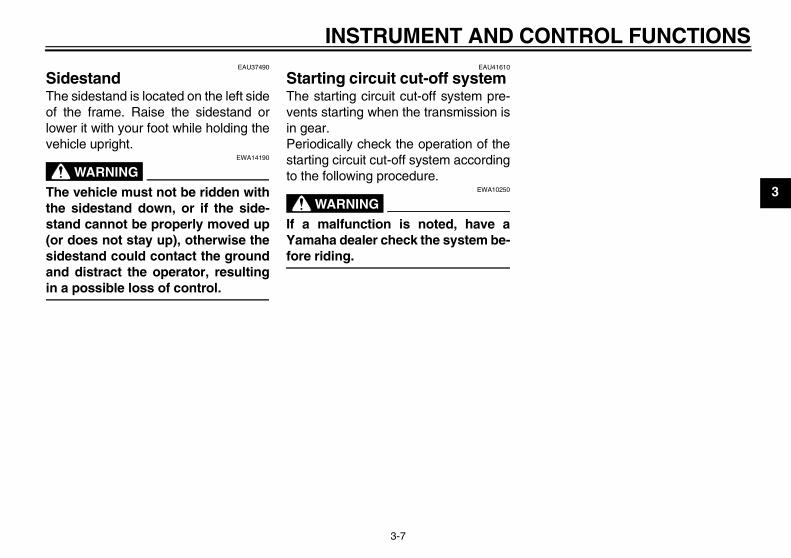
EAU37490
Sidestand The sidestand is located on the left sideof the frame. Raise the sidestand orlower it with your foot while holding thevehicle upright.
WARNINGEWA14190
The vehicle must not be ridden withthe sidestand down, or if the side-stand cannot be properly moved up(or does not stay up), otherwise thesidestand could contact the groundand distract the operator, resultingin a possible loss of control.
EAU41610
Starting circuit cut-off system The starting circuit cut-off system pre-vents starting when the transmission isin gear.Periodically check the operation of thestarting circuit cut-off system accordingto the following procedure.
WARNINGEWA10250
If a malfunction is noted, have aYamaha dealer check the system be-fore riding.
U5B610E0.book Page 7 Thursday, July 12, 2007 1:41 PM
INSTRUMENT AND CONTROL FUNCTIONS
3-8
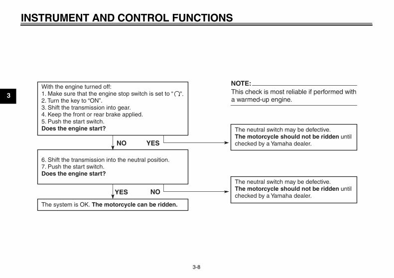
3With the engine turned off:1. Make sure that the engine stop switch is set to “ ”.2. Turn the key to “ON”. 3. Shift the transmission into gear.4. Keep the front or rear brake applied.5. Push the start switch.Does the engine start? The neutral switch may be defective.
The motorcycle should not be ridden until checked by a Yamaha dealer.
6. Shift the transmission into the neutral position.7. Push the start switch.Does the engine start?
The neutral switch may be defective.The motorcycle should not be ridden until checked by a Yamaha dealer.
YES
NOTE:
a warmed-up engine.
NO
The system is OK. The motorcycle can be ridden.
YES NO
This check is most reliable if performed with
U5B610E0.book Page 8 Thursday, July 12, 2007 1:41 PM
PRE-OPERATION CHECKS
4-1
4
EAU15593
The condition of a vehicle is the owner’s responsibility. Vital components can start to deteriorate quickly and unexpectedly,even if the vehicle remains unused (for example, as a result of exposure to the elements). Any damage, fluid leakage or lossof tire air pressure could have serious consequences. Therefore, it is very important, in addition to a thorough visual inspec-tion, to check the following points before each ride.
NOTE:Pre-operation checks should be made each time the vehicle is used. Such an inspection can be accomplished in a very shorttime; and the added safety it assures is more than worth the time involved.
WARNINGEWA11150
If any item in the Pre-operation check list is not working properly, have it inspected and repaired before operatingthe vehicle.
U5B610E0.book Page 1 Thursday, July 12, 2007 1:41 PM
PRE-OPERATION CHECKS
4-2
4
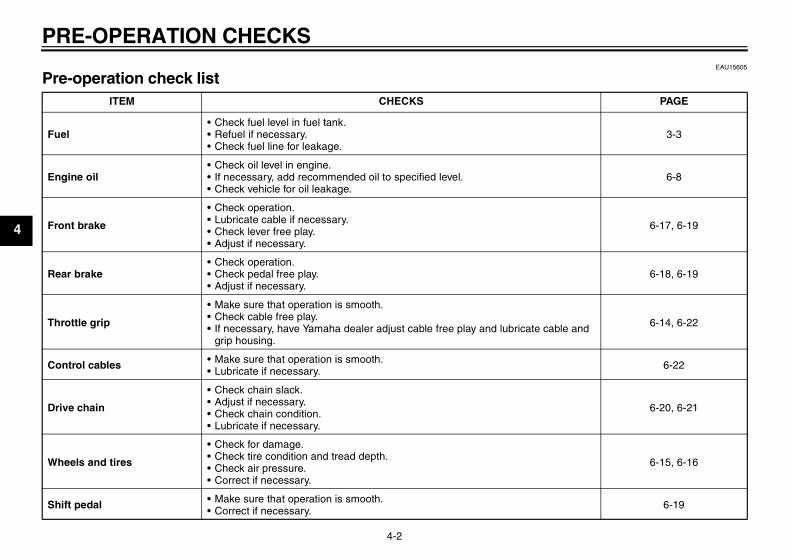
EAU15605
Pre-operation check list ITEM CHECKS PAGE
Fuel• Check fuel level in fuel tank.• Refuel if necessary.• Check fuel line for leakage.
3-3
Engine oil• Check oil level in engine.• If necessary, add recommended oil to specified level.• Check vehicle for oil leakage.
6-8
Front brake
• Check operation.• Lubricate cable if necessary.• Check lever free play.• Adjust if necessary.
6-17, 6-19
Rear brake• Check operation.• Check pedal free play.• Adjust if necessary.
6-18, 6-19
Throttle grip
• Make sure that operation is smooth.• Check cable free play.• If necessary, have Yamaha dealer adjust cable free play and lubricate cable and
grip housing.
6-14, 6-22
Control cables • Make sure that operation is smooth.• Lubricate if necessary. 6-22
Drive chain
• Check chain slack.• Adjust if necessary.• Check chain condition.• Lubricate if necessary.
6-20, 6-21
Wheels and tires
• Check for damage.• Check tire condition and tread depth.• Check air pressure.• Correct if necessary.
6-15, 6-16
Shift pedal • Make sure that operation is smooth.• Correct if necessary. 6-19
U5B610E0.book Page 2 Thursday, July 12, 2007 1:41 PM
PRE-OPERATION CHECKS
4-3
4
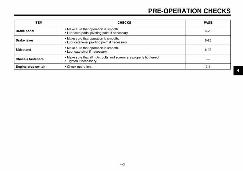
Brake pedal • Make sure that operation is smooth.• Lubricate pedal pivoting point if necessary. 6-23
Brake lever • Make sure that operation is smooth.• Lubricate lever pivoting point if necessary. 6-23
Sidestand • Make sure that operation is smooth.• Lubricate pivot if necessary. 6-23
Chassis fasteners • Make sure that all nuts, bolts and screws are properly tightened.• Tighten if necessary. —
Engine stop switch • Check operation. 3-1
ITEM CHECKS PAGE
U5B610E0.book Page 3 Thursday, July 12, 2007 1:41 PM

OPERATION AND IMPORTANT RIDING POINTS
5-1
5
EAU41680
WARNINGEWA14620
� This model is designed for off-road use only. Become thor-oughly familiar with all operat-ing controls and their functionsbefore riding. Consult a Yamahadealer regarding any control orfunction that you do not thor-oughly understand.
� Never start the engine or oper-ate it in a closed area for anylength of time. Exhaust fumesare poisonous, and inhalingthem can cause loss of con-sciousness and death within ashort time. Always make surethat there is adequate ventila-tion.
� Before starting out, make surethat the sidestand is up. If thesidestand is not raised com-pletely, it could contact theground and distract the opera-tor, resulting in a possible lossof control.
EAU44810
Starting and warming up a cold engine
1. Turn the fuel cock lever to “ON”.2. Turn the key to “ON” and make
sure that the engine stop switch isset to “ ”.
3. Shift the transmission into the neu-tral position.
WARNINGEWA14410
� Be sure to shift the transmis-sion into neutral before startingthe engine.
� Never ride with the sidestanddown.
4. Turn the starter (choke) on andcompletely close the throttle. (Seepage 3-5.)
5. Start the engine by pushing thestart switch or by pushing the kick-starter lever down.
CAUTION:ECA11130
For maximum engine life, alwayswarm the engine up before startingoff. Never accelerate hard when theengine is cold!
6. When the engine is warm, turn thestarter (choke) off.
NOTE:The engine is warm when it respondsnormally to the throttle with the starter(choke) turned off.
U5B610E0.book Page 1 Thursday, July 12, 2007 1:41 PM
OPERATION AND IMPORTANT RIDING POINTS
5-2
5
EAU16640
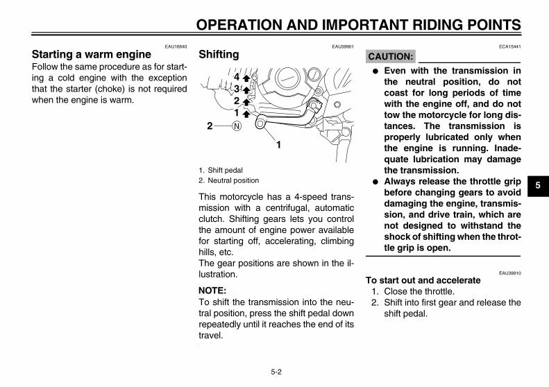
Starting a warm engine Follow the same procedure as for start-ing a cold engine with the exceptionthat the starter (choke) is not requiredwhen the engine is warm.
EAU39901
Shifting
This motorcycle has a 4-speed trans-mission with a centrifugal, automaticclutch. Shifting gears lets you controlthe amount of engine power availablefor starting off, accelerating, climbinghills, etc.The gear positions are shown in the il-lustration.
NOTE:To shift the transmission into the neu-tral position, press the shift pedal downrepeatedly until it reaches the end of itstravel.
CAUTION:ECA15441
� Even with the transmission inthe neutral position, do notcoast for long periods of timewith the engine off, and do nottow the motorcycle for long dis-tances. The transmission isproperly lubricated only whenthe engine is running. Inade-quate lubrication may damagethe transmission.
� Always release the throttle gripbefore changing gears to avoiddamaging the engine, transmis-sion, and drive train, which arenot designed to withstand theshock of shifting when the throt-tle grip is open.
EAU39910
To start out and accelerate1. Close the throttle.2. Shift into first gear and release the
shift pedal.
1. Shift pedal2. Neutral position
1
21234
U5B610E0.book Page 2 Thursday, July 12, 2007 1:41 PM
OPERATION AND IMPORTANT RIDING POINTS
5-3
5
CAUTION:ECA15460
Always close the throttle beforeshifting gears, otherwise damage tothe engine and drive train may re-sult.
3. Open the throttle gradually.4. Once the motorcycle has reached
a speed high enough to changegears, close the throttle.
5. Shift into second gear and releasethe shift pedal.
6. Open the throttle gradually.7. Follow the same procedure when
shifting to the next higher gear.
EAU16710
To decelerate1. Close the throttle and apply both
the front and the rear brakes toslow the motorcycle.
2. Downshift through the gears andshift the transmission into the neu-tral position when the motorcycleis almost completely stopped.
EAU39920
Engine break-in There is never a more important periodin the life of your engine than the first 5hours of riding. It is also important to ac-custom the rider to the motorcycle dur-ing this time. Please read the followinginformation carefully.Since the engine is brand new, do notput an excessive load on it for the first 5hours of operation. The various parts inthe engine wear and polish themselvesto the correct operating clearances.During this period, prolonged full-throt-tle operation or any condition that mightresult in engine overheating must beavoided. However, momentary full-throttle operation under load (i.e., twoto three seconds maximum) does notharm the engine. Each full-throttle ac-celeration should be followed with asubstantial rest period for the engine.To allow the engine to cool down fromthe temporary buildup of heat, cruise ata lower engine speed.After the first 5 hours of operation, thor-oughly check the motorcycle for looseparts, oil leakage and any other prob-lems. Be sure to inspect and make ad-
justments thoroughly, especially cableand drive chain slack and loosespokes. In addition, check all fittingsand fasteners for looseness, and tight-en if necessary.
CAUTION:ECA10270
If any engine trouble should occurduring the engine break-in period,immediately have a Yamaha dealercheck the vehicle.
U5B610E0.book Page 3 Thursday, July 12, 2007 1:41 PM

OPERATION AND IMPORTANT RIDING POINTS
5-4
5
EAU17170
Parking When parking, stop the engine, removethe key from the main switch, and thenturn the fuel cock lever to “OFF”.
WARNINGEWA10310
� Since the engine and exhaustsystem can become very hot,park in a place where pedestri-ans or children are not likely totouch them.
� Do not park on a slope or on softground, otherwise the vehiclemay overturn.
U5B610E0.book Page 4 Thursday, July 12, 2007 1:41 PM

PERIODIC MAINTENANCE AND MINOR REPAIR
6-2
6
EAU17310
Owner’s tool kit The service information included in thismanual and the tools provided in theowner’s tool kit are intended to assistyou in the performance of preventivemaintenance and minor repairs. How-ever, additional tools such as a torquewrench may be necessary to performcertain maintenance work correctly.
NOTE:If you do not have the tools or experi-ence required for a particular job, havea Yamaha dealer perform it for you.
WARNINGEWA10340
Modifications not approved byYamaha may cause loss of perfor-mance, excessive emissions, andrender the vehicle unsafe for use.Consult a Yamaha dealer before at-tempting any changes.
U5B610E0.book Page 2 Thursday, July 12, 2007 1:41 PM
PERIODIC MAINTENANCE AND MINOR REPAIR
6-3
6
EAU39943
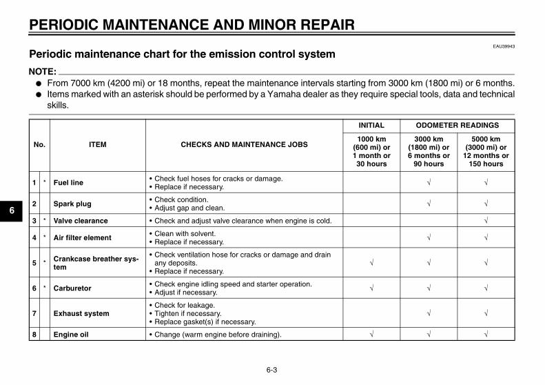
Periodic maintenance chart for the emission control system
NOTE:� From 7000 km (4200 mi) or 18 months, repeat the maintenance intervals starting from 3000 km (1800 mi) or 6 months.� Items marked with an asterisk should be performed by a Yamaha dealer as they require special tools, data and technical
skills.
No. ITEM CHECKS AND MAINTENANCE JOBS
INITIAL ODOMETER READINGS
1000 km (600 mi) or 1 month or 30 hours
3000 km (1800 mi) or 6 months or
90 hours
5000 km (3000 mi) or
12 months or 150 hours
1 * Fuel line • Check fuel hoses for cracks or damage.• Replace if necessary. √ √
2 Spark plug • Check condition.• Adjust gap and clean. √ √
3 * Valve clearance • Check and adjust valve clearance when engine is cold. √
4 * Air filter element • Clean with solvent.• Replace if necessary. √ √
5 * Crankcase breather sys-tem
• Check ventilation hose for cracks or damage and drain any deposits.
• Replace if necessary.√ √ √
6 * Carburetor • Check engine idling speed and starter operation.• Adjust if necessary. √ √ √
7 Exhaust system• Check for leakage.• Tighten if necessary.• Replace gasket(s) if necessary.
√ √
8 Engine oil • Change (warm engine before draining). √ √ √
U5B610E0.book Page 3 Thursday, July 12, 2007 1:41 PM

PERIODIC MAINTENANCE AND MINOR REPAIR
6-4
6
EAU35348
General maintenance and lubrication chart
No. ITEM CHECKS AND MAINTENANCE JOBS
INITIAL ODOMETER READINGS
1000 km (600 mi) or 1 month or 30 hours
3000 km (1800 mi) or 6 months or
90 hours
5000 km (3000 mi) or
12 months or 150 hours
1 * Clutch • Check operation.• Adjust if necessary. √ √ √
2 * Front brake• Check operation.• Adjust brake lever free play and replace brake shoes if
necessary.√ √ √
3 * Rear brake• Check operation.• Adjust brake pedal free play and replace brake shoes if
necessary.√ √ √
4 * Wheels • Check runout, spoke tightness and for damage.• Tighten spokes if necessary. √ √ √
5 * Tires
• Check tread depth and for damage.• Replace if necessary.• Check air pressure.• Correct if necessary.
√ √
6 * Wheel bearings • Check bearings for smooth operation.• Replace if necessary. √ √
7 * Swingarm pivot bearings • Check bearing assemblies for looseness.• Moderately repack with lithium-soap-based grease. √ √
8 Drive chain• Check chain slack/alignment and condition.• Adjust and lubricate chain with Yamaha chain and cable
lube thoroughly.Every ride
9 * Steering bearings • Check bearing assemblies for looseness.• Moderately repack with lithium-soap-based grease. √ √
U5B610E0.book Page 4 Thursday, July 12, 2007 1:41 PM

PERIODIC MAINTENANCE AND MINOR REPAIR
6-5
6
EAU40000
NOTE:The air filter needs more frequent service if you are riding in unusually wet or dusty areas.
10 * Chassis fasteners • Check all chassis fitting and fasteners.• Correct if necessary. √ √ √
11 Brake lever pivot shaft • Apply lithium-soap-based grease lightly. √ √
12 Brake pedal pivot shaft • Apply lithium-soap-based grease lightly. √ √
13 Sidestand pivot • Check operation.• Apply lithium-soap-based grease lightly. √ √
14 * Spark arrester • Clean. √
15 * Front fork • Check operation and for oil leakage.• Replace if necessary. √ √
16 * Shock absorber assem-bly
• Check operation and for oil leakage.• Replace if necessary. √
17 * Control cables • Apply Yamaha chain and cable lube or engine oil 10W-30 thoroughly. √ √ √
18 * Throttle grip housing and cable
• Check operation and free play.• Adjust the throttle cable free play if necessary.• Lubricate the throttle grip housing and cable.
√ √ √
No. ITEM CHECKS AND MAINTENANCE JOBS
INITIAL ODOMETER READINGS
1000 km (600 mi) or 1 month or 30 hours
3000 km (1800 mi) or 6 months or
90 hours
5000 km (3000 mi) or
12 months or 150 hours
U5B610E0.book Page 5 Thursday, July 12, 2007 1:41 PM

PERIODIC MAINTENANCE AND MINOR REPAIR
6-6
6
EAU18771
Removing and installing pan-els The panels shown need to be removedto perform some of the maintenancejobs described in this chapter. Refer tothis section each time a panel needs tobe removed and installed.
EAU41110
Panel A
To remove the panel1. Remove the seat. (See page 3-6.)2. Remove the bolts and the quick
fastener screws, and then take thepanel off.
To install the panel1. Place the panel in the original posi-
tion, and then install the bolts andthe quick fastener screws.
2. Install the seat.
EAU33020
Panel B
To remove the panel1. Remove the seat. (See page 3-6.)2. Remove the bolt, and then pull the
panel off as shown.
1. Panel A
11. Panel B
1
1. Panel A2. Bolt3. Quick fastener screw
3
1
2
3
U5B610E0.book Page 6 Thursday, July 12, 2007 1:41 PM

PERIODIC MAINTENANCE AND MINOR REPAIR
6-7
6
To install the panel1. Place the panel in the original posi-
tion, and then install the bolt.2. Install the seat.
EAU19603
Checking the spark plug The spark plug is an important enginecomponent, which is easy to check.Since heat and deposits will cause anyspark plug to slowly erode, the sparkplug should be removed and checkedin accordance with the periodic mainte-nance and lubrication chart. In addition,the condition of the spark plug can re-veal the condition of the engine.
To remove the spark plug1. Remove the spark plug cap.
2. Remove the spark plug as shown,with the spark plug wrench includ-ed in the owner’s tool kit.
To check the spark plug1. Check that the porcelain insulator
around the center electrode of thespark plug is a medium-to-light tan(the ideal color when the vehicle isridden normally).
NOTE:If the spark plug shows a distinctly dif-ferent color, the engine could be oper-ating improperly. Do not attempt todiagnose such problems yourself. In-stead, have a Yamaha dealer checkthe vehicle.
1. Panel B2. Bolt3. Projection
3
12
1. Spark plug cap
1
1. Spark plug wrench
1
U5B610E0.book Page 7 Thursday, July 12, 2007 1:41 PM
PERIODIC MAINTENANCE AND MINOR REPAIR
6-8
6
2. Check the spark plug for electrodeerosion and excessive carbon orother deposits, and replace it ifnecessary.
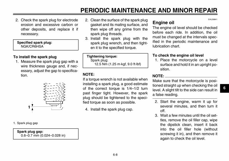
To install the spark plug1. Measure the spark plug gap with a
wire thickness gauge and, if nec-essary, adjust the gap to specifica-tion.
2. Clean the surface of the spark pluggasket and its mating surface, andthen wipe off any grime from thespark plug threads.
3. Install the spark plug with thespark plug wrench, and then tight-en it to the specified torque.
NOTE:If a torque wrench is not available wheninstalling a spark plug, a good estimateof the correct torque is 1/4–1/2 turnpast finger tight. However, the sparkplug should be tightened to the speci-fied torque as soon as possible.
4. Install the spark plug cap.
EAU39841
Engine oil The engine oil level should be checkedbefore each ride. In addition, the oilmust be changed at the intervals spec-ified in the periodic maintenance andlubrication chart.
To check the engine oil level1. Place the motorcycle on a level
surface and hold it in an upright po-sition.
NOTE:Make sure that the motorcycle is posi-tioned straight up when checking the oillevel. A slight tilt to the side can result ina false reading.
2. Start the engine, warm it up forseveral minutes, and then turn itoff.
3. Wait a few minutes until the oil set-tles, remove the oil filler cap, wipethe dipstick clean, insert it backinto the oil filler hole (withoutscrewing it in), and then remove itagain to check the oil level.
Specified spark plug:NGK/CR6HSA
1. Spark plug gap
Spark plug gap:0.6–0.7 mm (0.024–0.028 in)
Tightening torque:Spark plug:
12.5 Nm (1.25 m·kgf, 9.0 ft·lbf)
U5B610E0.book Page 8 Thursday, July 12, 2007 1:41 PM

PERIODIC MAINTENANCE AND MINOR REPAIR
6-9
6NOTE:The engine oil should be between theminimum and maximum level marks.
4. If the engine oil is at or below theminimum level mark, add sufficientoil of the recommended type toraise it to the correct level.
5. Insert the dipstick into the oil fillerhole, and then tighten the oil fillercap.
To change the engine oil1. Start the engine, warm it up for
several minutes, and then turn itoff.
2. Place an oil pan under the engineto collect the used oil.
3. Remove the engine oil filler capand drain bolt to drain the oil fromthe crankcase.
4. Install the engine oil drain bolt, andthen tighten it to the specifiedtorque.
5. Add the specified amount of therecommended engine oil, and theninstall and tighten the engine oil fill-er cap.
CAUTION:ECA11620
� In order to prevent clutch slip-page (since the engine oil alsolubricates the clutch), do notmix any chemical additives. Donot use oils with a diesel speci-fication of “CD” or oils of a high-er quality than specified. Inaddition, do not use oils labeled“ENERGY CONSERVING II” orhigher.
� Make sure that no foreign mate-rial enters the crankcase.
6. Start the engine, and then let it idlefor several minutes while checkingit for oil leakage. If oil is leaking, im-mediately turn the engine off andcheck for the cause.
1. Engine oil filler cap2. Dipstick3. Maximum level mark4. Minimum level mark
1
34
2
1. Engine oil drain bolt
Tightening torque:Engine oil drain bolt:
20 Nm (2.0 m·kgf, 14 ft·lbf)
1
Recommended engine oil:See page 8-1.
Oil change quantity:0.80 L (0.85 US qt) (0.70 Imp.qt)
U5B610E0.book Page 9 Thursday, July 12, 2007 1:41 PM

PERIODIC MAINTENANCE AND MINOR REPAIR
6-10
6
7. Turn the engine off, and thencheck the oil level and correct it ifnecessary.
EAU41633
Cleaning the air filter element The air filter element should be cleanedat the intervals specified in the periodicmaintenance and lubrication chart.Clean the air filter element more fre-quently if you are riding in unusuallywet or dusty areas.
To clean the air filter element1. Remove panel A. (See page 6-6.)2. Remove the air filter case cover by
removing the screws.
3. Pull the sponge material and themesh out.
4. Clean the mesh with solvent, andthen wipe the solvent off.
5. Clean the sponge material withsolvent, and then squeeze the re-maining solvent out.
WARNINGEWA10430
Use only a dedicated parts cleaningsolvent. To avoid the risk of fire orexplosion, do not use gasoline orsolvents with a low flash point.
CAUTION:ECA10510
To avoid damaging the foam materi-al, handle it gently and carefully, anddo not twist or wring it.
1. Air filter case cover2. Screw
2
1
1. Sponge material2. Air filter mesh
1
2
U5B610E0.book Page 10 Thursday, July 12, 2007 1:41 PM

PERIODIC MAINTENANCE AND MINOR REPAIR
6-11
6
6. Apply oil of the recommended typeto the entire surface of the spongematerial, and then squeeze the ex-cess oil out.
NOTE:The sponge material should be wet butnot dripping.
7. Insert the mesh and the spongematerial into the air filter case.
CAUTION:ECA15571
� Make sure that the mesh and thesponge material are properlyseated in the air filter case.
� The engine should never be op-erated without the mesh and thesponge material installed, oth-erwise the piston(s) and/or cyl-inder(s) may becomeexcessively worn.
8. Install the air filter case cover by in-stalling the screws.
NOTE:Make sure that the spark plug cable isrouted as shown.
9. Install the panel.
To clean the air filter check hose1. Check the hoses at the bottom of
the air filter case for accumulateddirt or water.
Recommended oil:Yamaha foam air filter oil or other quality foam air filter oil
1. Spark plug cable
1. Air filter check hose
1
1
1
U5B610E0.book Page 11 Thursday, July 12, 2007 1:41 PM

PERIODIC MAINTENANCE AND MINOR REPAIR
6-12
6
2. If dirt or water is visible, removethe hoses, clean them, and thenreinstall them.
EAU40421
Cleaning the spark arrester The spark arrester should be cleanedat the intervals specified in the periodicmaintenance and lubrication chart.
WARNINGEWA10980
� Always let the exhaust systemcool prior to touching exhaustcomponents.
� Do not start the engine whencleaning the exhaust system.
NOTE:Make sure to select a well-ventilatedarea free of combustible materials toclean the spark arrester.
1. Remove the tailpipe by removingthe bolts, and then pulling it out ofthe muffler.
2. Tap the tailpipe lightly, and thenuse a wire brush to remove anycarbon deposits from the spark ar-rester portion of the tailpipe and in-side of the tailpipe housing.
1. Tailpipe2. Bolt
1. Spark arrester
2
1
1
U5B610E0.book Page 12 Thursday, July 12, 2007 1:41 PM

PERIODIC MAINTENANCE AND MINOR REPAIR
6-13
6
3. Insert the tailpipe into the muffler,and then install and tighten thebolts to the specified torque.
NOTE:Make sure to align the bolt holes wheninserting the tailpipe.
EAU39930
Adjusting the carburetor The carburetor is an important part ofthe engine and requires very sophisti-cated adjustment. Therefore, most car-buretor adjustments should be left to aYamaha dealer, who has the neces-sary professional knowledge and expe-rience. The adjustment described in thefollowing section, however, may be ser-viced by the owner as part of routinemaintenance.
CAUTION:ECA10550
The carburetor has been set and ex-tensively tested at the Yamaha fac-tory. Changing these settingswithout sufficient technical knowl-edge may result in poor perfor-mance of or damage to the engine.
EAU21362
Adjusting the engine idling speed The engine idling speed must bechecked and, if necessary, adjusted asfollows at the intervals specified in theperiodic maintenance and lubricationchart.
NOTE:A diagnostic tachometer is needed tomake this adjustment.
1. Attach the tachometer to the sparkplug lead.
2. Start the engine and warm it up forseveral minutes at 1000–2000r/min while occasionally revving itto 4000–5000 r/min.
NOTE:The engine is warm when it quickly re-sponds to the throttle.
3. Check the engine idling speedand, if necessary, adjust it to spec-ification by turning the throttle stopscrew. To increase the engineidling speed, turn the screw in di-
Tightening torque:Tailpipe bolt:
10 Nm (1.0 m·kgf, 7.2 ft·lbf)
U5B610E0.book Page 13 Thursday, July 12, 2007 1:41 PM

PERIODIC MAINTENANCE AND MINOR REPAIR
6-14
6
rection (a). To decrease the en-gine idling speed, turn the screw indirection (b).
NOTE:If the specified idling speed cannot beobtained as described above, have aYamaha dealer make the adjustment.
EAU21382
Checking the throttle cable free play
The throttle cable free play should mea-sure 4.0–6.0 mm (0.16–0.24 in) at thethrottle grip. Periodically check thethrottle cable free play and, if neces-sary, have a Yamaha dealer adjust it.
EAU21401
Valve clearance The valve clearance changes with use,resulting in improper air-fuel mixtureand/or engine noise. To prevent thisfrom occurring, the valve clearancemust be adjusted by a Yamaha dealerat the intervals specified in the periodicmaintenance and lubrication chart.
1. Throttle stop screw
Engine idling speed:1600–1800 r/min
1
(a) (b)
1
1. Throttle cable free play
1
U5B610E0.book Page 14 Thursday, July 12, 2007 1:41 PM
PERIODIC MAINTENANCE AND MINOR REPAIR
6-15
6
EAU39820
Tires To maximize the performance, durabil-ity, and safe operation of your motor-cycle, note the following pointsregarding the specified tires.
Tire air pressureThe tire air pressure should be checkedand, if necessary, adjusted before eachride.
WARNINGEWA14380
� The tire air pressure must bechecked and adjusted on coldtires (i.e., when the temperatureof the tires equals the ambienttemperature).
� The tire air pressure must be ad-justed in accordance with theweight of the rider, the ridingspeed, and the riding condi-tions.
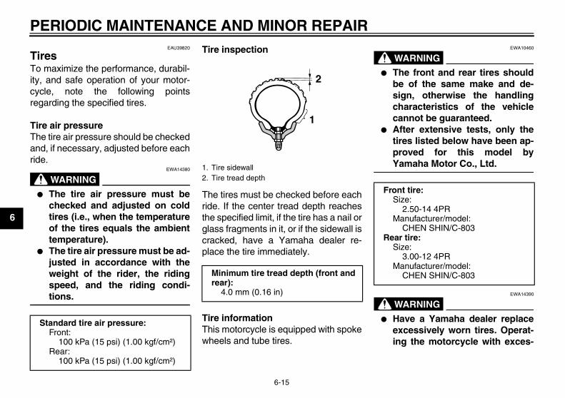
Tire inspection
The tires must be checked before eachride. If the center tread depth reachesthe specified limit, if the tire has a nail orglass fragments in it, or if the sidewall iscracked, have a Yamaha dealer re-place the tire immediately.
Tire informationThis motorcycle is equipped with spokewheels and tube tires.
WARNINGEWA10460
� The front and rear tires shouldbe of the same make and de-sign, otherwise the handlingcharacteristics of the vehiclecannot be guaranteed.
� After extensive tests, only thetires listed below have been ap-proved for this model byYamaha Motor Co., Ltd.
WARNINGEWA14390
� Have a Yamaha dealer replaceexcessively worn tires. Operat-ing the motorcycle with exces-
Standard tire air pressure:Front:
100 kPa (15 psi) (1.00 kgf/cm²)Rear:
100 kPa (15 psi) (1.00 kgf/cm²)
1. Tire sidewall2. Tire tread depth
Minimum tire tread depth (front and rear):
4.0 mm (0.16 in)
1
2
Front tire:Size:
2.50-14 4PRManufacturer/model:
CHEN SHIN/C-803Rear tire:
Size:3.00-12 4PR
Manufacturer/model:CHEN SHIN/C-803
U5B610E0.book Page 15 Thursday, July 12, 2007 1:41 PM

PERIODIC MAINTENANCE AND MINOR REPAIR
6-16
6
sively worn tires decreasesriding stability and can lead toloss of control.
� The replacement of all wheel-and brake-related parts, includ-ing the tires, should be left to aYamaha dealer, who has thenecessary professional knowl-edge and experience.
� It is not recommended to patcha punctured tube. If unavoid-able, however, patch the tubevery carefully and replace it assoon as possible with a high-quality product.
EAU21940
Spoke wheels To maximize the performance, durabil-ity, and safe operation of your motor-cycle, note the following pointsregarding the specified wheels.
� The wheel rims should be checkedfor cracks, bends or warpage, andthe spokes for looseness or dam-age before each ride. If any dam-age is found, have a Yamahadealer replace the wheel. Do notattempt even the smallest repair tothe wheel. A deformed or crackedwheel must be replaced.
� The wheel should be balancedwhenever either the tire or wheelhas been changed or replaced. Anunbalanced wheel can result inpoor performance, adverse han-dling characteristics, and a short-ened tire life.
� Ride at moderate speeds afterchanging a tire since the tire sur-face must first be “broken in” for itto develop its optimal characteris-tics.
EAU40431
Accessories and replacement parts
WARNINGEWA14481
The accessories or replacementparts you choose for your vehicleshould be designed specifically forthis model, and they must be se-curely mounted to maintain the in-herent stability of the originaldesign. Genuine Yamaha Parts andAccessories are designed and test-ed to be compatible with your vehi-cle. Yamaha recommends the use ofGenuine Yamaha Parts and Acces-sories before making a purchase.Use of non-Yamaha-approved ac-cessories or replacement parts maycause loss of handling stability andriding safety. Since Yamaha cannotcontrol the quality of accessories orparts manufactured by other compa-nies, Yamaha cannot be held liablefor any consequences caused bythe use of items which have notbeen approved by Yamaha.
U5B610E0.book Page 16 Thursday, July 12, 2007 1:41 PM

PERIODIC MAINTENANCE AND MINOR REPAIR
6-17
6
EAU44661
Adjusting the clutch free play The clutch free play must be checkedand, if necessary, adjusted as followsat the intervals specified in the periodicmaintenance and lubrication chart.
1. Loosen the locknut.2. Slowly turn the clutch adjusting
screw in direction (a) until resis-tance is felt, and then turn it 1/8turn in direction (b).
NOTE:Turning the clutch adjusting screw in di-rection (a) decreases clutch free playand turning it in direction (b) increasesclutch free play.
3. Tighten the locknut to the specifiedtorque.
NOTE:When tightening the locknut, hold theclutch adjusting screw with a screwdriv-er so that it does not turn together withthe locknut.
EAU44880
Adjusting the brake lever free play
The brake lever free play should mea-sure 10.0–20.0 mm (0.39–0.79 in) asshown. Periodically check the brake le-ver free play and, if necessary, adjust itas follows.
1. Loosen the locknut at the brake le-ver.
2. To increase the brake lever freeplay, turn the adjusting bolt in di-rection (a). To decrease the brakelever free play, turn the adjustingbolt in direction (b).
1. Locknut2. Clutch adjusting screw
1
2
(a)(b)
Tightening torque:Locknut:
8.0 Nm (0.8 m·kgf, 5.8 ft·lbf)
1. Brake lever free play adjusting bolt2. Locknut3. Brake lever free play
21(b)
3
(a)
U5B610E0.book Page 17 Thursday, July 12, 2007 1:41 PM

PERIODIC MAINTENANCE AND MINOR REPAIR
6-18
6
3. If the specified brake lever freeplay could be obtained as de-scribed above, tighten the locknutand skip the rest of the procedure,otherwise proceed as follows.
4. Fully turn the adjusting bolt at thebrake lever in direction (a) to loos-en the brake cable.
5. Loosen the locknut at the brakeshoe plate.
6. To increase the brake lever freeplay, turn the adjusting bolt in di-rection (a). To decrease the brakelever free play, turn the adjustingbolt in direction (b).
7. Tighten the locknut at the brakeshoe plate and at the brake lever.
EAU44670
Adjusting the brake pedal free play
The brake pedal free play should mea-sure 10.0–20.0 mm (0.39–0.79 in) atthe brake pedal end as shown. Period-ically check the brake pedal free playand, if necessary, adjust it as follows.To increase the brake pedal free play,turn the adjusting nut at the brake rod indirection (a). To decrease the brakepedal free play, turn the adjusting nut indirection (b).
WARNINGEWA14820
� After adjusting the drive chainslack or removing and installingthe rear wheel, always check thebrake pedal free play.
� If proper adjustment cannot beobtained as described, have aYamaha dealer make this ad-justment.
1. Locknut2. Brake lever free play adjusting bolt
2
1
(b)
(a)
1. Brake pedal free play adjusting nut2. Brake pedal free play
U5B610E0.book Page 18 Thursday, July 12, 2007 1:41 PM

PERIODIC MAINTENANCE AND MINOR REPAIR
6-19
6
EAU44820
Checking the shift pedal The operation of the shift pedal shouldbe checked before each ride. If opera-tion is not smooth, have a Yamahadealer check the vehicle.
EAU22361
Checking the front and rear brake shoes
Front
Rear
The front and rear brake shoes must bechecked for wear at the intervals spec-ified in the periodic maintenance andlubrication chart. Each brake is provid-ed with a wear indicator, which allowsyou to check the brake shoe wear with-out having to disassemble the brake.To check the brake shoe wear, checkthe position of the wear indicator whileapplying the brake. If a brake shoe hasworn to the point that the wear indicatorreaches the wear limit line, have aYamaha dealer replace the brakeshoes as a set.1. Brake shoe wear indicator
2. Brake shoe wear limit line
1. Brake shoe wear indicator2. Brake shoe wear limit line
2
1
12
U5B610E0.book Page 19 Thursday, July 12, 2007 1:41 PM
PERIODIC MAINTENANCE AND MINOR REPAIR
6-20
6
EAU22760
Drive chain slack The drive chain slack should bechecked before each ride and adjustedif necessary.
EAU22773
To check the drive chain slack1. Place the motorcycle on the side-
stand.
NOTE:When checking and adjusting the drivechain slack, there should be no weighton the motorcycle.
2. Shift the transmission into the neu-tral position.
3. Move the rear wheel by pushingthe motorcycle to locate the tight-est portion of the drive chain, andthen measure the drive chain slackas shown.
4. If the drive chain slack is incorrect,adjust it as follows.
EAU40110
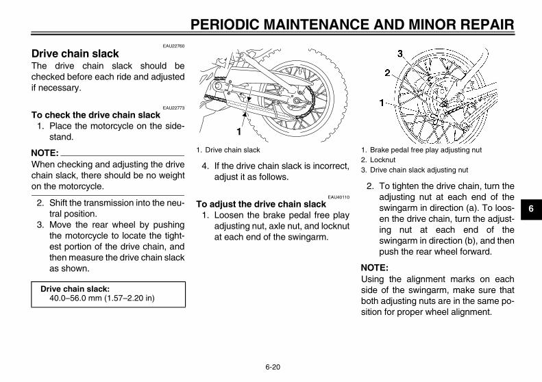
To adjust the drive chain slack1. Loosen the brake pedal free play
adjusting nut, axle nut, and locknutat each end of the swingarm.
2. To tighten the drive chain, turn theadjusting nut at each end of theswingarm in direction (a). To loos-en the drive chain, turn the adjust-ing nut at each end of theswingarm in direction (b), and thenpush the rear wheel forward.
NOTE:Using the alignment marks on eachside of the swingarm, make sure thatboth adjusting nuts are in the same po-sition for proper wheel alignment.
Drive chain slack:40.0–56.0 mm (1.57–2.20 in)
1. Drive chain slack
1
1. Brake pedal free play adjusting nut2. Locknut3. Drive chain slack adjusting nut
U5B610E0.book Page 20 Thursday, July 12, 2007 1:41 PM

PERIODIC MAINTENANCE AND MINOR REPAIR
6-21
6 CAUTION:ECA10570
Improper drive chain slack will over-load the engine as well as other vitalparts of the motorcycle and can leadto chain slippage or breakage. Toprevent this from occurring, keepthe drive chain slack within thespecified limits.
3. Tighten both locknuts and the axlenut to the specified torques.
4. Adjust the brake pedal free play.(See page 6-18.)
EAU23013
Cleaning and lubricating the drive chain The drive chain must be cleaned andlubricated at the intervals specified inthe periodic maintenance and lubrica-tion chart, otherwise it will quickly wearout, especially when riding in dusty orwet areas. Service the drive chain asfollows.
CAUTION:ECA10581
The drive chain must be lubricatedafter washing the motorcycle andriding in the rain.
1. Remove all dirt and mud from thedrive chain with a brush or cloth.
NOTE:For a thorough cleaning, have aYamaha dealer remove the drive chainand soak it in solvent.
2. Spray Yamaha Chain and CableLube or a high-quality spray-typedrive chain lubricant on both sidesand on the middle of the chain,
1. Axle nut2. Drive chain slack adjusting nut3. Locknut4. Alignment marks
Tightening torques:Locknut:
7.0 Nm (0.7 m·kgf, 5.1 ft·lbf)Axle nut:
60 Nm (6.0 m·kgf, 43 ft·lbf)
U5B610E0.book Page 21 Thursday, July 12, 2007 1:41 PM
PERIODIC MAINTENANCE AND MINOR REPAIR
6-22
6
making sure that all side platesand rollers have been sufficientlyoiled.
EAU23091
Checking and lubricating the cables The operation of all control cables andthe condition of the cables should bechecked before each ride, and the ca-bles and cable ends should be lubricat-ed if necessary. If a cable is damagedor does not move smoothly, have aYamaha dealer check or replace it.
WARNINGEWA10710
Damage to the outer housing of ca-bles may result in internal rustingand cause interference with cablemovement. Replace damaged ca-bles as soon as possible to preventunsafe conditions.
EAU23111
Checking and lubricating the throttle grip and cable The operation of the throttle grip shouldbe checked before each ride. In addi-tion, the cable should be lubricated atthe intervals specified in the periodicmaintenance chart.
Recommended lubricant:Yamaha Chain and Cable Lube or engine oil SAE 10W-30
U5B610E0.book Page 22 Thursday, July 12, 2007 1:41 PM

PERIODIC MAINTENANCE AND MINOR REPAIR
6-23
6
EAU43621
Checking and lubricating the brake lever
The operation of the brake lever shouldbe checked before each ride, and thelever pivots should be lubricated if nec-essary.
EAU23182
Checking and lubricating the brake pedal
The operation of the brake pedalshould be checked before each ride,and the pedal pivot should be lubricat-ed if necessary.
EAU23201
Checking and lubricating the sidestand
The operation of the sidestand shouldbe checked before each ride, and thesidestand pivot and metal-to-metalcontact surfaces should be lubricated ifnecessary.
WARNINGEWA10730
If the sidestand does not move upand down smoothly, have a Yamahadealer check or repair it.
Recommended lubricant:Lithium-soap-based grease
Recommended lubricant:Lithium-soap-based grease
Recommended lubricant:Lithium-soap-based grease
U5B610E0.book Page 23 Thursday, July 12, 2007 1:41 PM

PERIODIC MAINTENANCE AND MINOR REPAIR
6-24
6
EAUM1650
Lubricating the swingarm piv-ots
The swingarm pivots must be lubricat-ed at the intervals specified in the peri-odic maintenance and lubrication chart.
EAU23271
Checking the front fork The condition and operation of the frontfork must be checked as follows at theintervals specified in the periodic main-tenance and lubrication chart.
To check the condition
WARNINGEWA10750
Securely support the vehicle so thatthere is no danger of it falling over.
Check the inner tubes for scratches,damage and excessive oil leakage.
To check the operation1. Place the vehicle on a level sur-
face and hold it in an upright posi-tion.
2. While applying the front brake,push down hard on the handlebarsseveral times to check if the frontfork compresses and reboundssmoothly.
CAUTION:ECA10590
If any damage is found or the frontfork does not operate smoothly,have a Yamaha dealer check or re-pair it.
Recommended lubricant:Lithium-soap-based grease
U5B610E0.book Page 24 Thursday, July 12, 2007 1:41 PM

PERIODIC MAINTENANCE AND MINOR REPAIR
6-25
6
EAU23280
Checking the steering Worn or loose steering bearings maycause danger. Therefore, the operationof the steering must be checked as fol-lows at the intervals specified in the pe-riodic maintenance and lubricationchart.
1. Place a stand under the engine toraise the front wheel off theground.
WARNINGEWA10750
Securely support the vehicle so thatthere is no danger of it falling over.
2. Hold the lower ends of the frontfork legs and try to move them for-ward and backward. If any freeplay can be felt, have a Yamahadealer check or repair the steering.
EAU23290
Checking the wheel bearings The front and rear wheel bearings mustbe checked at the intervals specified inthe periodic maintenance and lubrica-tion chart. If there is play in the wheelhub or if the wheel does not turnsmoothly, have a Yamaha dealer checkthe wheel bearings.
U5B610E0.book Page 25 Thursday, July 12, 2007 1:41 PM
PERIODIC MAINTENANCE AND MINOR REPAIR
6-26
6
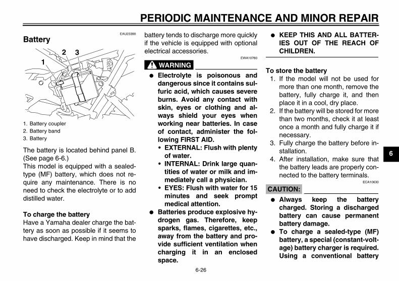
EAU23390
Battery
The battery is located behind panel B.(See page 6-6.)This model is equipped with a sealed-type (MF) battery, which does not re-quire any maintenance. There is noneed to check the electrolyte or to adddistilled water.
To charge the batteryHave a Yamaha dealer charge the bat-tery as soon as possible if it seems tohave discharged. Keep in mind that the
battery tends to discharge more quicklyif the vehicle is equipped with optionalelectrical accessories.
WARNINGEWA10760
� Electrolyte is poisonous anddangerous since it contains sul-furic acid, which causes severeburns. Avoid any contact withskin, eyes or clothing and al-ways shield your eyes whenworking near batteries. In caseof contact, administer the fol-lowing FIRST AID.• EXTERNAL: Flush with plenty
of water.• INTERNAL: Drink large quan-
tities of water or milk and im-mediately call a physician.
• EYES: Flush with water for 15minutes and seek promptmedical attention.
� Batteries produce explosive hy-drogen gas. Therefore, keepsparks, flames, cigarettes, etc.,away from the battery and pro-vide sufficient ventilation whencharging it in an enclosedspace.
� KEEP THIS AND ALL BATTER-IES OUT OF THE REACH OFCHILDREN.
To store the battery1. If the model will not be used for
more than one month, remove thebattery, fully charge it, and thenplace it in a cool, dry place.
2. If the battery will be stored for morethan two months, check it at leastonce a month and fully charge it ifnecessary.
3. Fully charge the battery before in-stallation.
4. After installation, make sure thatthe battery leads are properly con-nected to the battery terminals.
CAUTION:ECA10630
� Always keep the batterycharged. Storing a dischargedbattery can cause permanentbattery damage.
� To charge a sealed-type (MF)battery, a special (constant-volt-age) battery charger is required.Using a conventional battery
1. Battery coupler2. Battery band3. Battery
2 31
U5B610E0.book Page 26 Thursday, July 12, 2007 1:41 PM

PERIODIC MAINTENANCE AND MINOR REPAIR
6-27
6
charger will damage the battery.If you do not have access to asealed-type (MF) battery charg-er, have a Yamaha dealercharge your battery.
EAU42021
Replacing the fuse
The fuse is located inside the batterycoupler. (See page 6-26.)If the fuse is blown, replace it as fol-lows.
1. Turn the key to “OFF” and turn offall electrical circuits.
2. Disconnect the battery coupler.3. Remove the blown fuse, and then
install a new fuse of the specifiedamperage.
CAUTION:ECA10640
Do not use a fuse of a higher amper-age rating than recommended toavoid causing extensive damage tothe electrical system and possibly afire.
4. Connect the battery coupler.5. Turn the key to “ON” and turn on
the electrical circuits to check if thedevices operate.
6. If the fuse immediately blowsagain, have a Yamaha dealercheck the electrical system.
1. Fuse2. Spare fuse
Specified fuse:10.0 A
12
U5B610E0.book Page 27 Thursday, July 12, 2007 1:41 PM

PERIODIC MAINTENANCE AND MINOR REPAIR
6-28
6
EAU24350
Supporting the motorcycle Since this model is not equipped with acenterstand, follow these precautionswhen removing the front and rearwheel or performing other maintenancerequiring the motorcycle to stand up-right. Check that the motorcycle is in astable and level position before startingany maintenance. A strong woodenbox can be placed under the engine foradded stability.
To service the front wheel1. Stabilize the rear of the motorcycle
by using a motorcycle stand or, ifan additional motorcycle stand isnot available, by placing a jack un-der the frame in front of the rearwheel.
2. Raise the front wheel off theground by using a motorcyclestand.
To service the rear wheelRaise the rear wheel off the ground byusing a motorcycle stand or, if a motor-cycle stand is not available, by placing
a jack either under each side of theframe in front of the rear wheel or undereach side of the swingarm.
EAU24360
Front wheel
EAU41810
To remove the front wheel
WARNINGEWA10820
� It is advisable to have a Yamahadealer service the wheel.
� Securely support the motor-cycle so that there is no dangerof it falling over.
1. Loosen the locknut at the brake le-ver, and then turn the adjustingbolt fully in direction (a).
2. Loosen the axle nut.
1. Brake lever free play adjusting bolt2. Locknut
21
(a)
U5B610E0.book Page 28 Thursday, July 12, 2007 1:41 PM
PERIODIC MAINTENANCE AND MINOR REPAIR
6-29
6
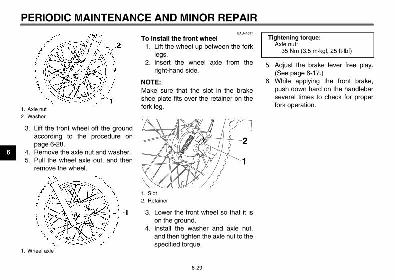
3. Lift the front wheel off the groundaccording to the procedure onpage 6-28.
4. Remove the axle nut and washer.5. Pull the wheel axle out, and then
remove the wheel.
EAU41691
To install the front wheel1. Lift the wheel up between the fork
legs.2. Insert the wheel axle from the
right-hand side.
NOTE:Make sure that the slot in the brakeshoe plate fits over the retainer on thefork leg.
3. Lower the front wheel so that it ison the ground.
4. Install the washer and axle nut,and then tighten the axle nut to thespecified torque.
5. Adjust the brake lever free play.(See page 6-17.)
6. While applying the front brake,push down hard on the handlebarseveral times to check for properfork operation.
1. Axle nut2. Washer
1. Wheel axle
1. Slot2. Retainer
2
1
Tightening torque:Axle nut:
35 Nm (3.5 m·kgf, 25 ft·lbf)
U5B610E0.book Page 29 Thursday, July 12, 2007 1:41 PM

PERIODIC MAINTENANCE AND MINOR REPAIR
6-30
6
EAU25080
Rear wheel
EAU41642
To remove the rear wheel
WARNINGEWA10820
� It is advisable to have a Yamahadealer service the wheel.
� Securely support the motor-cycle so that there is no dangerof it falling over.
1. Disconnect the brake torque rodfrom the brake shoe plate by re-moving the cotter pin, the nut andthe bolt.
2. Remove the brake pedal free playadjusting nut, and then disconnectthe brake rod at the brake cam-shaft lever.
3. Loosen the locknut and the drivechain slack adjusting nut on bothends of the swingarm.
4. Loosen the axle nut.5. Lift the rear wheel off the ground
according to the procedure onpage 6-28.
6. Remove the axle nut and washer,and then pull the wheel axle out.
7. Push the wheel forward, and thenremove the drive chain from therear sprocket.
1. Brake torque rod2. Cotter pin3. Brake torque rod bolt and nut4. Brake shoe plate
1. Brake rod2. Brake pedal free play adjusting nut3. Brake camshaft lever4. Wheel axle
1. Axle nut2. Washer3. Drive chain slack adjusting nut4. Locknut
1 2 4
3
U5B610E0.book Page 30 Thursday, July 12, 2007 1:41 PM
PERIODIC MAINTENANCE AND MINOR REPAIR
6-31
6
NOTE:The drive chain does not need to bedisassembled in order to remove andinstall the wheel.
8. Remove the wheel.
EAU41652
To install the rear wheel1. Install the drive chain onto the rear
sprocket.2. Insert the wheel axle from the
right-hand side.3. Adjust the drive chain slack. (See
page 6-20.)4. Lower the rear wheel so that it is
on the ground.
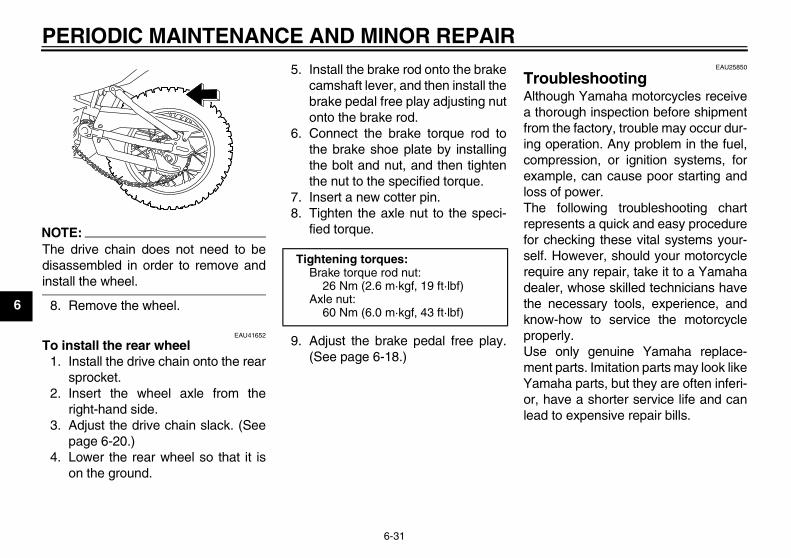
5. Install the brake rod onto the brakecamshaft lever, and then install thebrake pedal free play adjusting nutonto the brake rod.
6. Connect the brake torque rod tothe brake shoe plate by installingthe bolt and nut, and then tightenthe nut to the specified torque.
7. Insert a new cotter pin.8. Tighten the axle nut to the speci-
fied torque.
9. Adjust the brake pedal free play.(See page 6-18.)
EAU25850
Troubleshooting Although Yamaha motorcycles receivea thorough inspection before shipmentfrom the factory, trouble may occur dur-ing operation. Any problem in the fuel,compression, or ignition systems, forexample, can cause poor starting andloss of power.The following troubleshooting chartrepresents a quick and easy procedurefor checking these vital systems your-self. However, should your motorcyclerequire any repair, take it to a Yamahadealer, whose skilled technicians havethe necessary tools, experience, andknow-how to service the motorcycleproperly.Use only genuine Yamaha replace-ment parts. Imitation parts may look likeYamaha parts, but they are often inferi-or, have a shorter service life and canlead to expensive repair bills.
Tightening torques:Brake torque rod nut:
26 Nm (2.6 m·kgf, 19 ft·lbf)Axle nut:
60 Nm (6.0 m·kgf, 43 ft·lbf)
U5B610E0.book Page 31 Thursday, July 12, 2007 1:41 PM

PERIODIC MAINTENANCE AND MINOR REPAIR
6-32
6
EAU25901
Troubleshooting chart
WARNINGEWA10840
Keep away open flames and do not smoke while checking or working on the fuel system.
Check the fuel level inthe fuel tank.
1. FuelThere is enough fuel.
There is no fuel.
Check the compression.
Supply fuel. The engine does not start. Check the compression.
Operate the electric starter.
2. CompressionThere is compression.
There is no compression.
Check the ignition.
Have a Yamaha dealercheck the vehicle.
Remove the spark plugand check the electrodes.
3. Ignition Wipe off with a dry cloth and correct thespark plug gap, or replace the spark plug.
Have a Yamaha dealer check the vehicle.
The engine does not start.Have a Yamaha dealercheck the vehicle.
The engine does not start.Check the battery.
Operate the electric starter.
4. BatteryThe engine turns over quickly.
The engine turns over slowly.
The battery is good.
Check the battery lead connections,and charge the battery if necessary.
Dry
WetOpen the throttle halfway and operatethe electric starter.
U5B610E0.book Page 32 Thursday, July 12, 2007 1:41 PM

MOTORCYCLE CARE AND STORAGE
7-1
7
EAU37833
Matte color caution
CAUTION:ECA15192
Some models are equipped withmatte colored finished parts. Besure to consult a Yamaha dealer foradvice on what products to use be-fore cleaning the vehicle. Using abrush, harsh chemical products orcleaning compounds when cleaningthese parts will scratch or damagetheir surface. Wax also should notbe applied to any matte colored fin-ished parts.
EAU40462
Care While the open design of a motorcyclereveals the attractiveness of the tech-nology, it also makes it more vulnera-ble. Rust and corrosion can developeven if high-quality components areused. A rusty exhaust pipe may go un-noticed on a car, however, it detractsfrom the overall appearance of a motor-cycle. Frequent and proper care doesnot only comply with the terms of thewarranty, but it will also keep yourmotorcycle looking good, extend its lifeand optimize its performance.
Before cleaning1. Cover the muffler outlet with a
plastic bag after the engine hascooled down.
2. Make sure that all caps and coversas well as all electrical couplersand connectors, including thespark plug cap, are tightly in-stalled.
3. Remove extremely stubborn dirt,like oil burnt onto the crankcase,with a degreasing agent and abrush, but never apply such prod-
ucts onto seals, gaskets, sprock-ets, the drive chain and wheelaxles. Always rinse the dirt and de-greaser off with water.
Cleaning
CAUTION:ECA10771
� Avoid using strong acidic wheelcleaners, especially on spokedwheels. If such products areused on hard-to-remove dirt, donot leave the cleaner on the af-fected area any longer than in-structed. Also, thoroughly rinsethe area off with water, immedi-ately dry it, and then apply a cor-rosion protection spray.
� Improper cleaning can damageplastic parts such as cowlings,panels, windshields, headlightlenses, meter lenses, etc. Useonly a soft, clean cloth orsponge with mild detergent andwater to clean plastic.
� Do not use any harsh chemicalproducts on plastic parts. Besure to avoid using cloths orsponges which have been in
U5B610E0.book Page 1 Thursday, July 12, 2007 1:41 PM

MOTORCYCLE CARE AND STORAGE
7-2
7
contact with strong or abrasivecleaning products, solvent orthinner, fuel (gasoline), rust re-movers or inhibitors, brake flu-id, antifreeze or electrolyte.
� Do not use high-pressure wash-ers or steam-jet cleaners sincethey cause water seepage anddeterioration in the following ar-eas: seals (of wheel and swing-arm bearings, fork and brakes),electric components (couplers,connectors, instruments,switches and lights), breatherhoses and vents.
� For motorcycles equipped witha windshield: Do not use strongcleaners or hard sponges asthey will cause dulling orscratching. Some cleaning com-pounds for plastic may leavescratches on the windshield.Test the product on a small hid-den part of the windshield tomake sure that it does not leaveany marks. If the windshield is
scratched, use a quality plasticpolishing compound afterwashing.
After normal useRemove dirt with warm water, a milddetergent, and a soft, clean sponge,and then rinse thoroughly with cleanwater. Use a toothbrush or bottlebrushfor hard-to-reach areas. Stubborn dirtand insects will come off more easily ifthe area is covered with a wet cloth fora few minutes before cleaning.After riding in the rain or near the seaSince sea salt is extremely corrosive,carry out the following steps after eachride in the rain or near the sea.
1. Clean the motorcycle with cold wa-ter and a mild detergent, after theengine has cooled down.
CAUTION:ECA10790
Do not use warm water since it in-creases the corrosive action of thesalt.
2. Apply a corrosion protection sprayon all metal, including chrome- andnickel-plated, surfaces to preventcorrosion.
After cleaning1. Dry the motorcycle with a chamois
or an absorbing cloth.2. Immediately dry the drive chain
and lubricate it to prevent it fromrusting.
3. Use a chrome polish to shinechrome, aluminum and stainless-steel parts, including the exhaustsystem. (Even the thermally in-duced discoloring of stainless-steel exhaust systems can be re-moved through polishing.)
4. To prevent corrosion, it is recom-mended to apply a corrosion pro-tection spray on all metal,including chrome- and nickel-plat-ed, surfaces.
5. Use spray oil as a universal clean-er to remove any remaining dirt.
6. Touch up minor paint damagecaused by stones, etc.
7. Wax all painted surfaces.8. Let the motorcycle dry completely
before storing or covering it.
WARNINGEWA14500
� Make sure that there is no oil orwax on the tires.
U5B610E0.book Page 2 Thursday, July 12, 2007 1:41 PM

MOTORCYCLE CARE AND STORAGE
7-3
7
� If necessary, wash the tires withwarm water and a mild deter-gent. Before riding at higherspeeds, test the motorcycle’sbraking performance and cor-nering behavior.
CAUTION:ECA10800
� Apply spray oil and wax spar-ingly and make sure to wipe offany excess.
� Never apply oil or wax to anyrubber and plastic parts, buttreat them with a suitable careproduct.
� Avoid using abrasive polishingcompounds as they will wearaway the paint.
NOTE:Consult a Yamaha dealer for advice onwhat products to use.
EAU26150
Storage
Short-termAlways store your motorcycle in a cool,dry place and, if necessary, protect itagainst dust with a porous cover.
CAUTION:ECA10810
� Storing the motorcycle in apoorly ventilated room or cover-ing it with a tarp, while it is stillwet, will allow water and humid-ity to seep in and cause rust.
� To prevent corrosion, avoiddamp cellars, stables (becauseof the presence of ammonia)and areas where strong chemi-cals are stored.
Long-termBefore storing your motorcycle for sev-eral months:
1. Follow all the instructions in the“Care” section of this chapter.
2. For motorcycles equipped with afuel cock that has an “OFF” posi-tion: Turn the fuel cock lever to“OFF”.
3. Drain the carburetor float chamberby loosening the drain bolt; this willprevent fuel deposits from buildingup. Pour the drained fuel into thefuel tank.
4. Fill up the fuel tank and add fuelstabilizer (if available) to preventthe fuel tank from rusting and thefuel from deteriorating.
5. Perform the following steps to pro-tect the cylinder, piston rings, etc.from corrosion.a. Remove the spark plug cap
and spark plug.b. Pour a teaspoonful of engine oil
into the spark plug bore.c. Install the spark plug cap onto
the spark plug, and then placethe spark plug on the cylinderhead so that the electrodes aregrounded. (This will limit spark-ing during the next step.)
d. Turn the engine over severaltimes with the starter. (This willcoat the cylinder wall with oil.)
e. Remove the spark plug capfrom the spark plug, and theninstall the spark plug and thespark plug cap.
U5B610E0.book Page 3 Thursday, July 12, 2007 1:41 PM
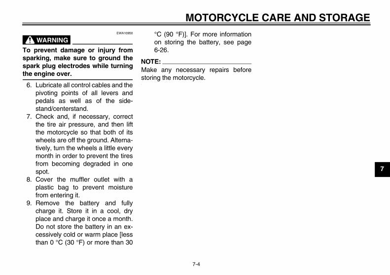
MOTORCYCLE CARE AND STORAGE
7-4
7
WARNINGEWA10950
To prevent damage or injury fromsparking, make sure to ground thespark plug electrodes while turningthe engine over.
6. Lubricate all control cables and thepivoting points of all levers andpedals as well as of the side-stand/centerstand.
7. Check and, if necessary, correctthe tire air pressure, and then liftthe motorcycle so that both of itswheels are off the ground. Alterna-tively, turn the wheels a little everymonth in order to prevent the tiresfrom becoming degraded in onespot.
8. Cover the muffler outlet with aplastic bag to prevent moisturefrom entering it.
9. Remove the battery and fullycharge it. Store it in a cool, dryplace and charge it once a month.Do not store the battery in an ex-cessively cold or warm place [lessthan 0 °C (30 °F) or more than 30
°C (90 °F)]. For more informationon storing the battery, see page6-26.
NOTE:Make any necessary repairs beforestoring the motorcycle.
U5B610E0.book Page 4 Thursday, July 12, 2007 1:41 PM

SPECIFICATIONS
8-1
8
Dimensions:Overall length:
1565 mm (61.6 in)Overall width:
680 mm (26.8 in)Overall height:
923 mm (36.3 in)Seat height:
670 mm (26.4 in)Wheelbase:
1080 mm (42.5 in)Ground clearance:
180 mm (7.09 in)Minimum turning radius:
1660 mm (65.4 in)Weight:
With oil and fuel:72.0 kg (159 lb)
Engine:Engine type:
Air cooled 4-stroke, SOHCCylinder arrangement:
Forward-inclined single cylinderDisplacement:
110.0 cm³Bore × stroke:
51.0 × 54.0 mm (2.01 × 2.13 in)Compression ratio:
9.30 :1Starting system:
Electric starter and kickstarterLubrication system:
Wet sump
Engine oil:Type:
YAMALUBE 4, SAE10W-30 or SAE20W-40
Recommended engine oil grade:API service SG type or higher, JASO standard MA
Engine oil quantity:Periodic oil change:
0.80 L (0.85 US qt) (0.70 Imp.qt)Air filter:
Air filter element:Wet element
Fuel:Recommended fuel:
Unleaded gasoline onlyFuel tank capacity:
3.8 L (1.00 US gal) (0.84 Imp.gal)Fuel reserve amount:
0.5 L (0.13 US gal) (0.11 Imp.gal)
Carburetor:Manufacturer:
MIKUNIType × quantity:
VM16 x 1Spark plug (s):
Manufacturer/model:NGK/CR6HSA
Spark plug gap:0.6–0.7 mm (0.024–0.028 in)
Clutch:Clutch type:
Wet, multiple-disc and centrifugal automatic
Transmission:Primary reduction system:
Spur gearPrimary reduction ratio:
67/18 (3.722)Secondary reduction system:
Chain driveSecondary reduction ratio:
35/14 (2.500)Transmission type:
Constant mesh 4-speedOperation:
Left foot operationGear ratio:
1st:38/12 (3.166)
2nd:33/17 (1.941)
3rd:29/21 (1.380)
10˚ 30˚ 50˚ 70˚ 90˚ 110˚0˚ 130 ˚F
YAMALUBE 4 (10W-30)or SAE 10W-30
YAMALUBE 4 (20W-40)or SAE 20W-40
–10˚ 0˚ 10˚ 20˚ 30˚ 40˚–20˚ 50 ˚C
U5B610E0.book Page 1 Thursday, July 12, 2007 1:41 PM

SPECIFICATIONS
8-2
8
4th:23/21 (1.095)
Chassis:Frame type:
Steel tube backboneCaster angle:
26.00 °Trail:
60.0 mm (2.36 in)Front tire:
Type:With tube
Size:2.50-14 4PR
Manufacturer/model:CHEN SHIN/C-803
Rear tire:Type:
With tubeSize:
3.00-12 4PRManufacturer/model:
CHEN SHIN/C-803Loading:
Maximum rider weight:60.0 kg (132 lb)
Tire air pressure (measured on cold tires):
Front:100 kPa (15 psi) (1.00 kgf/cm²)
Rear:100 kPa (15 psi) (1.00 kgf/cm²)
Front wheel:Wheel type:
Spoke wheelRim size:
14x1.40Rear wheel:
Wheel type:Spoke wheel
Rim size:12x1.60
Front brake:Type:
Drum brakeOperation:
Right hand operationRear brake:
Type:Drum brake
Operation:Right foot operation
Front suspension:Type:
Telescopic forkSpring/shock absorber type:
Coil spring/oil damperWheel travel:
115.0 mm (4.53 in)Rear suspension:
Type:Swingarm (monocross)
Spring/shock absorber type:Coil spring/gas-oil damper
Wheel travel:110.0 mm (4.33 in)
Electrical system:Ignition system:
DC. CDICharging system:
AC magnetoBattery:
Model:GT4B-5
Voltage, capacity:12 V, 2.5 Ah
Fuse:Fuse:
10.0 A
U5B610E0.book Page 2 Thursday, July 12, 2007 1:41 PM
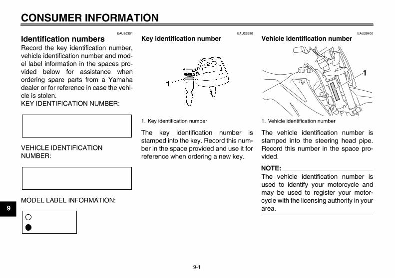
CONSUMER INFORMATION
9-1
9
EAU26351
Identification numbers Record the key identification number,vehicle identification number and mod-el label information in the spaces pro-vided below for assistance whenordering spare parts from a Yamahadealer or for reference in case the vehi-cle is stolen.KEY IDENTIFICATION NUMBER:
VEHICLE IDENTIFICATION NUMBER:
MODEL LABEL INFORMATION:
EAU26390
Key identification number
The key identification number isstamped into the key. Record this num-ber in the space provided and use it forreference when ordering a new key.
EAU26400
Vehicle identification number
The vehicle identification number isstamped into the steering head pipe.Record this number in the space pro-vided.
NOTE:The vehicle identification number isused to identify your motorcycle andmay be used to register your motor-cycle with the licensing authority in yourarea.
1. Key identification number 1. Vehicle identification number
1
U5B610E0.book Page 1 Thursday, July 12, 2007 1:41 PM

CONSUMER INFORMATION
9-2
9
EAU36980
Model label
The model label is affixed to the framebehind panel B. (See page 6-6.)Record the information on this label inthe space provided. This informationwill be needed when ordering spareparts from a Yamaha dealer.
1. Model label
1
U5B610E0.book Page 2 Thursday, July 12, 2007 1:41 PM

CONSUMER INFORMATION
9-3
9
EAU26560
Motorcycle noise regulation TAMPERING WITH NOISE CONTROL SYSTEM PROHIBITED:Federal law prohibits the following acts or the causing thereof: (1) The removal or rendering inoperative by any person otherthan for purposes of maintenance, repair, or replacement of any device or element of design incorporated into any new ve-hicle for the purpose of noise control prior to its sale or delivery to the ultimate purchaser or while it is in use or (2) the use ofthe vehicle after such device or element of design has been removed or rendered inoperative by any person.“AMONG THOSE ACTS PRESUMED TO CONSTITUTE TAMPERING ARE THE ACTS LISTED BELOW”.These acts include tampering with the following systems; i.e., modification, removal, etc.
Exhaust system• Muffler• Exhaust pipe• Silencer
Intake system• Air cleaner case• Air cleaner element• Intake duct
U5B610E0.book Page 3 Thursday, July 12, 2007 1:41 PM

CONSUMER INFORMATION
9-4
9
EAU38051
YAMAHA MOTOR CORPORATION, U.S.A. OFF-ROAD MOTORCYCLE LIMITED WARRANTY Yamaha Motor Corporation, USA hereby warrantsthat new Yamaha off-road motorcycles purchasedfrom an authorized Yamaha motorcycle dealer inthe continental United States will be free fromdefects in material and workmanship for the peri-od of time stated herein, subject to certain statedlimitations. Covered off-road motorcycles arethose units certified by Yamaha to EPA noise reg-ulations and come equipped from the factory withUSDA-FS approved spark arresters.
THE PERIOD OF WARRANTY for Yamaha off-road motorcycles shall be ninety (90) days fromthe date of purchase, with no mileage limitation.
PRODUCT EXCLUDED FROM WARRANTYinclude those used for non-Yamaha-authorizedrenting, leasing, or other commercial purposes.
DURING THE PERIOD OF WARRANTY anyauthorized Yamaha motorcycle dealer will free ofcharge, repair or replace, at Yamaha's option, anypart adjudged defective by Yamaha due to faultyworkmanship or material from the factory. Partsused in warranty repairs will be warranted for thebalance of the product's warranty period. All partsreplaced under warranty become property ofYamaha Motor Corporation, USA.
GENERAL EXCLUSIONS from this warrantyshall include any failures caused by:a. Competition or racing use.b. Installation of parts or accessories that are
not qualitatively equivalent to genuineYamaha parts.
c. Abnormal strain, neglect, or abuse.d. Lack of proper maintenance.e. Accident or collision damage.f. Modification to original parts.g. Damage due to improper transportation.
SPECIFIC EXCLUSIONS from this warranty shallinclude parts replaced due to normal wear or rou-tine maintenance.
THE CUSTOMER'S RESPONSIBILITY underthis warranty shall be to:1. Operate and maintain the motorcycle as
specified in the appropriate Owner's Manual,and
2. Give notice to an authorized Yamaha motor-cycle dealer of any and all apparent defectswithin ten (10) days after discovery, and makethe motorcycle available at that time forinspection and repairs at such dealer's placeof business.
WARRANTY TRANSFER: To transfer the warran-ty from the original purchaser to any subsequentpurchaser(s), it is imperative that the motorcyclebe inspected and registered for warranty by anauthorized Yamaha motorcycle dealer. In order forthis warranty to remain in effect, this inspectionand registration must take place within ten (10)days after transfer of ownership to the subse-quent purchaser. A reasonable dealer imposedfee may be charged for this inspection.
EMISSION CONTROL SYSTEM WARRANTYYamaha Motor Corporation, USA also warrants tothe ultimate purchaser and each subsequent pur-chaser of each 2006 and later model Yamahamotorcycle covered by this warranty that the vehi-cle is designed, built, and equipped so as to con-form at the time of sale with all U.S. emissionsstandards applicable at the time of manufactureand that it is free from defects in materials andworkmanship which would cause it not to meetthese standards within the period listed immedi-ately below. Failures other than those resultingfrom defects in material or workmanship which
arise solely as a result of owner abuse and/or lackof proper maintenance are not covered by thiswarranty.
All Off-Road ModelsThirty (30) months from the original purchasedate
YAMAHA MOTOR CORPORATION, USAMAKES NO OTHER WARRANTY OF ANYKIND, EXPRESSED OR IMPLIED. ALL IMPLIEDWARRANTIES OF MERCHANTABILITY ANDFITNESS FOR A PARTICULAR PURPOSEWHICH EXCEED THE OBLIGATIONS ANDTIME LIMITS STATED IN THIS WARRANTYARE HEREBY DISCLAIMED BY YAMAHAMOTOR CORPORATION, USA AND EXCLUD-ED FROM THIS WARRANTY.
SOME STATES DO NOT ALLOW LIMITATIONSON HOW LONG AN IMPLIED WARRANTYLASTS, SO THE ABOVE LIMITATION MAY NOTAPPLY TO YOU. ALSO EXCLUDED FROM THISWARRANTY ARE ANY INCIDENTAL OR CON-SEQUENTIAL DAMAGES INCLUDING LOSSOF USE. SOME STATES DO NOT ALLOW THEEXCLUSION OR LIMITATION OF INCIDENTALOR CONSEQUENTIAL DAMAGES, SO THEABOVE EXCLUSION MAY NOT APPLY TO YOU.
THIS WARRANTY GIVES YOU SPECIFICLEGAL RIGHTS, AND YOU MAY ALSO HAVEOTHER RIGHTS WHICH VARY FROM STATE TOSTATE.
YAMAHA MOTOR CORPORATION, USAPost Office Box 6555
Cypress, California 90630
U5B610E0.book Page 4 Thursday, July 12, 2007 1:41 PM

CONSUMER INFORMATION
9-5
9
U5B610E0.book Page 5 Thursday, July 12, 2007 1:41 PM
CONSUMER INFORMATION
9-6
9
EAU26750
YAMAHA EXTENDED SERVICE (Y.E.S.) Keep your Yamaha protected even after your warranty expires with genuine Yamaha Extended Service (Y.E.S.).
Y.E.S. is designed and administered by Yamaha Motor Corporation to provide maximum owner satisfaction. You get uninterrupted factory-backed coverage for extra peace of mind.
Y.E.S. is flexible. You choose the plan that’s right foryou: 12 months, 24 months, 36 months or, on certain models, even 48 months beyond your warranty period.
Y.E.S. is designed and administered by the same Yamaha people who handle your warranty – and itshows in the comprehensive coverage benefits. There are no mileage limitations. Coverage isn’t limited to “moving parts” or the “drive train” like many other plans. And Y.E.S. covers manufacturing defects just like the warranty. See the sample contract at your Yamahadealer to see how comforting uninterrupted factory-backed protection can be.
You don’t have to pay anything for covered repairs. There’s no deductible to pay, and repairs aren’t“pro-rated.” You don’t have any “out-of-pocket” expenses for covered repairs.
In addition, Travel and Recreation Interruption Protection (TRIP) is included at no extra cost. TRIP gives you up to $150 reimbursement per occurrence for any reasonable expenses you incur because your Yamaha needs covered service: replacement vehicle rental, emergency towing, phone calls, even food and lodging when you are away from home. This superb coverage goes into effect when you purchase Y.E.S., so it applies to any warranty repairs as well as covered repairs during your entire Y.E.S. plan period.
Y.E.S. coverage is honored at any authorized Yamaha dealer nationwide.
Y.E.S. coverage is transferable to a new owner if yousell or trade-in. That can make your Yamaha much more valuable!
This excellent Y.E.S. plan coverage is only available to Yamaha owners like you, and only while your Yamaha is still within the Yamaha Limited Warranty period. So visit your authorized Yamaha dealer to get all the facts. He can show you how easy it is to protect your investment with Yamaha Extended Service.
U5B610E0.book Page 6 Thursday, July 12, 2007 1:41 PM
CONSUMER INFORMATION
9-7
9
We urge you to act now. You’ll get the excellent benefits of TRIP coverage right away, and you’ll rest easy knowing you’ll have strong factory-backed protection even after your Yamaha Limited Warranty expires.
A special note:If visiting your dealer isn’t convenient, contact Yamaha with your Primary ID number (your frame number). We’ll be happy to help you get the Y.E.S. coverage you need.
Yamaha Service MarketingP.O. Box 6555Cypress, CA 906301-(866)-YES-EXTD (1-866-937-3983)
U5B610E0.book Page 7 Thursday, July 12, 2007 1:41 PM

INDEXA
Accessories and replacement parts ..... 6-16Air filter element, cleaning .................... 6-10
BBattery .................................................. 6-26Brake lever ............................................. 3-2Brake lever, checking and lubricating... 6-23Brake lever free play, adjusting ............ 6-17Brake pedal ............................................ 3-2Brake pedal, checking and
lubricating ........................................... 6-23Brake pedal free play, adjusting ........... 6-18Brake shoes, checking ......................... 6-19
CCables, checking and lubricating.......... 6-22Carburetor, adjusting ............................ 6-13Care........................................................ 7-1Clutch free play, adjusting .................... 6-17
DDrive chain, cleaning and lubricating.... 6-21Drive chain slack .................................. 6-20
EEngine break-in ...................................... 5-3Engine idling speed .............................. 6-13Engine oil ................................................ 6-8Engine, starting a warm.......................... 5-2Engine stop switch.................................. 3-1
FFront fork, checking .............................. 6-24Fuel......................................................... 3-3Fuel cock ................................................ 3-4Fuel tank breather hose.......................... 3-4Fuel tank cap .......................................... 3-3Fuse, replacing ..................................... 6-27
HHandlebar switches.................................3-1
IIdentification numbers .............................9-1
KKey identification number........................9-1Kickstarter ...............................................3-6
LLabels, location of ...................................1-4
MMain switch .............................................3-1Maintenance and lubrication, periodic.....6-4Maintenance, emission control system ...6-3Maintenance, periodic .............................6-1Matte color, caution.................................7-1Model label..............................................9-2
NNoise regulation ......................................9-3
PPanels, removing and installing ..............6-6Parking ....................................................5-4Part locations ..........................................2-1Pre-operation check list...........................4-2
SSafety information ...................................1-1Seat.........................................................3-6Shifting ....................................................5-2Shift pedal ...............................................3-2Shift pedal, checking .............................6-19Sidestand ................................................3-7Sidestand, checking and lubricating......6-23Spark arrester, cleaning ........................6-12Spark plug, checking...............................6-7Specifications ..........................................8-1
Starter (choke) lever ............................... 3-5Starting and warming up
a cold engine ........................................ 5-1Starting circuit cut-off system.................. 3-7Start switch ............................................. 3-1Steering, checking ................................ 6-25Storage ................................................... 7-3Supporting the motorcycle .................... 6-28Swingarm pivots, lubricating ................. 6-24
TThrottle cable free play, checking ......... 6-14Throttle grip and cable,
checking and lubricating ..................... 6-22Tires...................................................... 6-15Tool kit .................................................... 6-2Troubleshooting .................................... 6-31Troubleshooting chart ........................... 6-32
VValve clearance .................................... 6-14Vehicle identification number.................. 9-1
WWarranty, extended ................................ 9-6Warranty, limited..................................... 9-4Wheel bearings, checking..................... 6-25Wheel (front) ......................................... 6-28Wheel (rear).......................................... 6-30Wheels.................................................. 6-16
U5B610E0.book Page 1 Thursday, July 12, 2007 1:41 PM

A5-yoko_Blank.fm Page 1 Tuesday, April 8, 2003 11:43 AM

A5-yoko_Blank.fm Page 1 Tuesday, April 8, 2003 11:43 AM
PRINTED IN JAPAN2007.07-2.1×1 CR
(E)
PRINTED ON RECYCLED PAPER YAMAHA MOTOR CO., LTD.