ts-3ga-32.200(rel4)v4.1.0 telecommunication … · telecommunication management; charging...
TRANSCRIPT

TS-3GA-32.200(Rel4)v4.1.0
Telecommunication management; Charging management;
Charging principles
May 28, 2002
THE TELECOMMUNICATION TECHNOLOGY COMMITTEE

i
TS-3GA-32.200(Rel4)v4.1.0 Telecommunication management; Charging management; Charging principles <Remarks>
1. Application level of English description
Application level : E2
English description is included in the text and figures of main body, annexes and appendices.
2. Relationship with international recommendations and standards
This standard is standardized based on the Technical Specification 32.200(Version 4.1.0) approved by 3GPP.
3. Departures from international recommendations
Changes to original standard
Standards referred to in theoriginal standard, which are replaced by TTC standards.
Standards referred to in the original standard should be replaced by derived TTC standards.
4. IPR
There is no specific description about IPR in this standard.
5. Technical Committee
Technical Committee 6

3GPP TS 32.200 V4.1.0 (2002-03)Technical Specification
3rd Generation Partnership Project;Technical Specification Group Services and System Aspects;
Telecommunication management;Charging management;
Charging principles(Release 4)
The present document has been developed within the 3rd Generation Partnership Project (3GPP TM) and may be further elaborated for the purposes of 3GPP. The present document has not been subject to any approval process by the 3GPP Organizational Partners and shall not be implemented. This Specification is provided for future development work within 3GPP only. The Organizational Partners accept no liability for any use of this Specification.Specifications and reports for implementation of the 3GPP TM system should be obtained via the 3GPP Organizational Partners' Publications Offices.

3GPP
3GPP TS 32.200 V4.1.0 (2002-03)2Release 4
Keywords Charging, Call Event, Billing, Accounting
3GPP
Postal address
3GPP support office address 650 Route des Lucioles - Sophia Antipolis
Valbonne - FRANCE Tel.: +33 4 92 94 42 00 Fax: +33 4 93 65 47 16
Internet http://www.3gpp.org
Copyright Notification
No part may be reproduced except as authorized by written permission. The copyright and the foregoing restriction extend to reproduction in all media.
© 2002, 3GPP Organizational Partners (ARIB, CWTS, ETSI, T1, TTA, TTC).
All rights reserved.

3GPP
3GPP TS 32.200 V4.1.0 (2002-03)3Release 4
Contents
Foreword.............................................................................................................................................................5
Introduction ........................................................................................................................................................5
1 Scope ........................................................................................................................................................6 2 References ................................................................................................................................................7
3 Definitions, abbreviations and symbols ...................................................................................................8 3.1 Definitions ............................................................................................................................................................... 8 3.2 Abbreviations .......................................................................................................................................................... 9 3.3 Symbols ................................................................................................................................................................. 11 4 Architecture............................................................................................................................................12 4.1 3G logical and charging logical architecture ......................................................................................................... 12 4.2 Charging Gateway Function.................................................................................................................................. 14
5 Circuit-Switched Domain.......................................................................................................................16 5.1 Charging Principles ............................................................................................................................................... 16 5.1.1 Requirements according to TS 22.115............................................................................................................. 16 5.1.2 Charging Information ...................................................................................................................................... 16 5.1.2.1 Subscriber billing............................................................................................................................................. 17 5.1.2.2 Settlements of Charges .................................................................................................................................... 17 5.1.2.2.1 Inter-PLMN accounting ............................................................................................................................. 17 5.1.2.2.2 'Visitors' from other PLMNs ...................................................................................................................... 17 5.1.2.2.3 'Home' subscribers roaming in other PLMNs............................................................................................. 17 5.1.2.2.4 Fixed network operators and other service providers................................................................................. 17 5.1.2.3 Service Information ......................................................................................................................................... 18 5.1.3 General Aspects of Charging Data .................................................................................................................. 18 5.2 Collection of Charging Data Records.................................................................................................................... 18 5.2.1 Charging Data Record Generation................................................................................................................... 18 5.2.1.1 AoC service ..................................................................................................................................................... 19 5.2.1.2 CAMEL services ............................................................................................................................................. 19 5.2.1.3 Use of supplementary services......................................................................................................................... 19 5.2.1.4 Use of call forwarding ..................................................................................................................................... 20 5.2.1.5 Use of call hold and multi-party services......................................................................................................... 20 5.2.1.6 Partial records .................................................................................................................................................. 20 5.2.1.7 Use of circuit-switched data services............................................................................................................... 21 5.2.1.8 Inter-MSC server handover.............................................................................................................................. 22 5.2.1.9 Call re-establishment ....................................................................................................................................... 22 5.2.1.10 Restricted directory numbers...................................................................................................................... 22 5.2.1.11 IMEI Observation....................................................................................................................................... 22 5.2.2 Charging scenarios........................................................................................................................................... 23 5.2.2.1 Mobile to land (outgoing) call ......................................................................................................................... 24 5.2.2.2 Land to mobile (incoming) call........................................................................................................................ 25 5.2.2.3 Mobile to mobile call within the same network............................................................................................... 26 5.2.2.4 Incoming call to a roaming subscriber............................................................................................................. 27 5.2.2.5 Incoming call to a PLMN service centre ......................................................................................................... 28 5.2.2.6 Call forwarding unconditional ......................................................................................................................... 29 5.2.2.7 Call forwarding conditional (on busy) ............................................................................................................. 30 5.2.2.8 Delivery of a mobile terminated short message............................................................................................... 31 5.2.2.9 Call hold and multi-party service..................................................................................................................... 32 5.2.2.10 Outgoing call handled by CAMEL ............................................................................................................ 33 5.2.2.11 Incoming call handled by CAMEL without redirection ............................................................................. 35 5.2.2.12 Incoming call to a roaming subscriber handled by CAMEL...................................................................... 37 5.2.2.13 Incoming call handled by CAMEL with redirection decided and forwarding leg handled by CAMEL .... 39 5.2.2.14 Incoming call handled by CAMEL without redirection and forwarded early using GSM SS but
controlled by CAMEL.......................................................................................................................... 41

3GPP
3GPP TS 32.200 V4.1.0 (2002-03)4Release 4
5.2.2.15 Incoming call handled by CAMEL without redirection and forwarded late using GSM SS but controlled by CAMEL.......................................................................................................................... 43
5.2.2.16 Early forwarded call controlled by CAMEL .............................................................................................. 45 5.2.2.17 Late forwarded call controlled by CAMEL................................................................................................ 47 5.2.2.18 Incoming call handled by CAMEL with redirection initiated by CAMEL feature .................................... 49 5.2.2.19 CAMEL Scenario for Visiting Terminator Trigger Calls .......................................................................... 51 5.2.2.20 Outgoing call handled by CAMEL with Dialled CSI Trigger.................................................................... 53 5.2.2.21 Incoming call handled by CAMEL with redirection decided and forwarding leg handled by CAMEL
with Dialled CSI Trigger ...................................................................................................................... 55
6 Packet-Switched Domain .......................................................................................................................56 6.1 Charging Principles ............................................................................................................................................... 56 6.1.1 Requirements ................................................................................................................................................... 56 6.1.2 Charging Information ...................................................................................................................................... 57 6.1.3 General Aspects of Charging Data .................................................................................................................. 57 6.1.4 Volume counting in RNC ................................................................................................................................ 58 6.1.5 Generation of Charging ID .............................................................................................................................. 58 6.1.6 Charging for SMS............................................................................................................................................ 59 6.1.7 Charging support for CAMEL......................................................................................................................... 59 6.2 Charging Data Collection ...................................................................................................................................... 59 6.2.1 Charging Data Record Generation................................................................................................................... 60 6.2.1.1 Triggers for S-CDR Charging Information Collection .................................................................................... 60 6.2.1.1.1 Triggers for S-CDR Charging Information Addition ................................................................................. 60 6.2.1.1.2 Triggers for S-CDR Closure ...................................................................................................................... 60 6.2.1.2 Triggers for M-CDR Charging Information Collection................................................................................... 61 6.2.1.2.1 Triggers for M-CDR Charging Information Addition................................................................................ 61 6.2.1.2.2 Triggers for M-CDR Closure ..................................................................................................................... 61 6.2.1.3 Triggers for G-CDR Charging Information Collection.................................................................................... 62 6.2.2 Charging scenarios........................................................................................................................................... 62 6.2.2.1 Mobile to PDN Context ................................................................................................................................... 63 6.2.2.2 Mobile to Mobile Context................................................................................................................................ 63 6.2.2.3 PDN to Mobile Context ................................................................................................................................... 64 6.2.2.4 Mobile to PDN Context while roaming, GGSN in HPLMN ........................................................................... 65 7 Application Services ..............................................................................................................................65 7.1 Multimedia Messaging Service ............................................................................................................................. 66 7.1.1 Charging Principles.......................................................................................................................................... 66 7.1.1.1 Charging Information ...................................................................................................................................... 66 7.1.2 Charging scenarios........................................................................................................................................... 66
Annex A (informative): Change history ...............................................................................................70

3GPP
3GPP TS 32.200 V4.1.0 (2002-03)5Release 4
Foreword This Technical Specification has been produced by the 3rd Generation Partnership Project (3GPP).
The contents of the present document are subject to continuing work within the TSG and may change following formal TSG approval. Should the TSG modify the contents of the present document, it will be re-released by the TSG with an identifying change of release date and an increase in version number as follows:
Version x.y.z
where:
x the first digit:
1 presented to TSG for information;
2 presented to TSG for approval;
3 or greater indicates TSG approved document under change control.
y the second digit is incremented for all changes of substance, i.e. technical enhancements, corrections, updates, etc.
z the third digit is incremented when editorial only changes have been incorporated in the document.
Introduction The present document is part of a set of TSs which describe the requirements and information necessary for the standardised charging of 3G system.

3GPP
3GPP TS 32.200 V4.1.0 (2002-03)6Release 4
1 Scope The present document describes the principles of charging and billing for the provision of service and services by a 3G system.
The present document elaborates on the charging requirements described in the Charging Principles in 3GPP TS 22.101 [1]. It allows the generation of accurate charging information to be used in the commercial and contractual relationships between the parties concerned. The present document is not intended to duplicate existing standards or standards being developed by other groups on these topics, and references these where appropriate.
The charging data records (CDRs) generated by the network elements of the 3G network, are required for a number of telecom management activities including, but not limited to, the following:
- the billing of home subscribers, either directly or via service providers, for network utilisation charges;
- the settlement of accounts for traffic carried or services performed by fixed network operators and other operators;
- the settlement of accounts with other PLMNs for roaming traffic via the transferred account procedure;
- statistical analysis of service usage;
- as archival information in dealing with customer service and billing complaints.
In addition to the information collected from network elements, network management functions are required for the administration of charging data.
The present document is part of a series of documents specifying charging functionality in UMTS networks. The UMTS charging architecture and principles are specified in the present document which provides an umbrella for other charging documents that specify the structure and content of the CDRs and the interface protocol that is used to transfer them to the collecting node. The CDRs used in the Circuit Switched (CS) domain are specified in document TS 32.205 [5]. The CDRs content and transport within the PS domain are described in TS 32.215 [6] document, while CDRs used for application services are defined in document TS 32.235 [17].
The relationship among these charging specifications is illustrated in figure 1.
32.200Charging Principles(charging stage 2)
32.205Stage 3
CS-domain
32.215Stage 3
PS-domain
32.225Reserved forStage 3 IMS
(R5)
32.235Stage 3
Service-domain(R4: MMS service)
Figure 1: Charging Documents Structure
For the purpose of the present document, the charging data is considered to be generated and collected by charging functions in the network elements.
Charging data fields are collected and CDRs generated by the network elements for transfer to the billing system. For the packet switched domain, the CDRs are first sent to the Charging Gateway Function (CGF) for storage and further processing. The CGF may be a distinct network element or may be integrated into the packet domain network elements themselves.

3GPP
3GPP TS 32.200 V4.1.0 (2002-03)7Release 4
The objectives of the present document are:
- to describe principles of charging in a 3G network;
- to provide a description of the charging architecture; and
- to provide the descriptions of events and triggers for the generation of Charging Data Records (CDRs).
2 References The following documents contain provisions which, through reference in this text, constitute provisions of the present document.
• References are either specific (identified by date of publication, edition number, version number, etc.) or non-specific.
• For a specific reference, subsequent revisions do not apply.
• For a non-specific reference, the latest version applies. In the case of a reference to a 3GPP document (including a GSM document), a non-specific reference implicitly refers to the latest version of that document in the same Release as the present document.
[1] 3GPP TS 22.101: "Service aspects; Service Principles".
[2] 3GPP TS 22.115 "Service aspects; Charging and Billing".
[3] 3GPP TS 32.101 "3G Telecom Management: Principles and high level requirements".
[4] 3GPP TS 32.102 "3G Telecom Management architecture".
[5] 3GPP TS 32.205: "Telecommunication management; Charging management; 3G charging data description for the Circuit Switched (CS) domain".
[6] 3GPP TS 32.215: "3G Telecom Management; Charging management; Charging data description for the Packet Switched (PS) domain".
[7] 3GPP TS 22.024: "Description of Charge Advice Information (CAI)".
[8] 3GPP TS 22.086: "Advice of charge (AoC) supplementary services - Stage 1".
[9] 3GPP TS 24.008: "Mobile radio interface layer 3 specification; Core Network Protocols; Stage 3".
[10] GSM 12.00: "Digital cellular telecommunication system (Phase 2); Network Management (NM); Part 1: Objectives and structure of network management".
[11] GSM 12.01: "Digital cellular telecommunication system (Phase 2); Network Management (NM); Part 2: Common aspects of GSM/DCS 1800 network management".
[12] 3GPP TS 29.060: "General Packet Radio Service (GPRS); GPRS Tunnelling Protocol (GTP) across the Gn and Gp Interface".
[13] 3GPP TS 23.078: "Customised Applications for Mobile network Enhanced Logic (CAMEL) - Phase 3; Stage 2".
[14] 3GPP TS 29.078: "Customised Application for Mobile network Enhanced Logic (CAMEL) Phase 3; CAMEL Application Part (CAP) specification".
[15] IETF RFC 959 (1985): "File Transfer Protocol"; J. Postel, J. Reynolds, ISI.
[16] IETF RFC 783 (1981): "TFTP Protocol (revision 2)"; K.R. Sollins MIT.
[17] 3GPP TS 32.235: "Telecommunication management; Charging management; Charging data description for application services".

3GPP
3GPP TS 32.200 V4.1.0 (2002-03)8Release 4
[18] ITU-T Recommendation D.93: "Charging and accounting in the international land mobile telephone service (provided via cellular radio systems)".
[19] 3GPP TS 23 140: "Multimedia Messaging Service (MMS); Functional Description; Stage 2".
[20] 3GPP TR 21.905: "Vocabulary for 3GPP Specifications".
[21] 3GPP TS 23.002: "Network Architecture (Release 4)".
[22] 3GPP TS 23.009: "Handover Procedures".
[23] 3GPP TS 24.086: "Advice of charge (AoC) supplementary services - Stage 3".
3 Definitions, abbreviations and symbols
3.1 Definitions For the purposes of the present document, the terms and definitions given in TR 21.905 [20] and the following apply:
(GSM only): qualifier indicating that this clause or paragraph applies only to a GSM system For multi-system cases this is determined by the current serving radio access network.
(UMTS only): qualifier indicating that this clause or paragraph applies only to a UMTS system For multi-system cases this is determined by the current serving radio access network.
real time: real time charging and billing information is to be generated, processed, and transported to a desired conclusion in less than 1 s
near real time: near real time charging and billing information is to be generated, processed, and transported to a desired conclusion in less than 1 minute
2G- / 3G-: prefixes 2G- and 3G- refers to functionality that supports only GSM or UMTS, respectively, e.g., 2G-SGSN refers only to the GSM functionality of an SGSN When the prefix is omitted, reference is made independently from the GSM or UMTS functionality.
in GSM,...: qualifier indicating that this paragraph applies only to GSM System For multi system cases this is determined by the current serving radio access network.
in UMTS,...: qualifier indicating that this paragraph applies only to UMTS System For multi system cases this is determined by the current serving radio access network.
accounting meter record: record containing one or more counters employed to register the usage of resources en masse Includes simple event counters and/ or cumulative call second counters.
accounting: process of apportioning charges between the Home Environment, Serving Network and User
advice of charge: real-time display of the network utilisation charges incurred by the Mobile Station The charges are displayed in the form of charging units. If a unit price is stored by the MS then the display may also include the equivalent charge in the home currency.
aoc service: combination of one or more services, both basic and supplementary, together with a number of other charging relevant parameters to define a customised service for the purpose of advice of charge
billing: function whereby CDRs generated by the charging function are transformed into bills requiring payment
CAMEL: network feature that provides the mechanisms to support operator specific services even when roaming outside HPLMN
CAMEL subscription information: identifies a subscriber as having CAMEL services

3GPP
3GPP TS 32.200 V4.1.0 (2002-03)9Release 4
Charging Data Record (CDR): record generated by a network element for the purpose of billing a subscriber for the provided service It includes fields identifying the user, the session and the network elements as well as information on the network resources and services used to support a subscriber session. In the traditional circuit domain, CDR has been used to denote "Call Detail Record", which is subsumed by "Charging Data Record" hereafter.
chargeable event: activity utilising telecommunications network infrastructure and related services for user to user communication (e.g. a single call, a data communication session or a short message), or for user to network communication (e.g. service profile administration), or for inter-network communication (e.g. transferring calls, signalling, or short messages), or for mobility (e.g. roaming or inter-system handover), which the network operator wants to charge for
charged party: user involved in a chargeable event who has to pay parts or the whole charges of the chargeable event, or a third party paying the charges caused by one or all users involved in the chargeable event, or a network operator
charging: function whereby information related to a chargeable event is formatted and transferred in order to make it possible to determine usage for which the charged party may be billed
circuit switched domain: domain within UMTS in which information is transferred in circuit mode
domain: part of a communication network that provides services using a certain technology
GPRS: Packet Services for GSM and UMTS systems
inter-system change: change of radio access between different radio access technologies such as GSM and UMTS
observed IMEI ticket: record used to describe an EIR relevant event e.g. a blacklisted IMEI
packet switched domain: domain within UMTS in which data is transferred in packet mode
settlement: payment of amounts resulting from the accounting process
short time: time, typically in number of minutes, to perform the off-line mechanism used for accounting
successful transaction: circuit connection that reaches the communication or data transfer phase e.g. the "answered" state for speech connections A packet connection that achieves completed data transfer. All other connection attempts are regarded as unsuccessful.
tariff period: part of one (calendar) day during which a particular tariff is applied Defined by the time at which the period commences (the switch-over time) and the tariff to be applied after switch-over.
tariff: set of parameters defining the network utilisation charges for the use of a particular service
3.2 Abbreviations For the purposes of the present document, the following abbreviations apply:
3G 3rd Generation 3GPP 3G Partnership Project AoC Advice of Charge APN Access Point Name BMD Billing Mediation Device BS Billing System CAI Charge Advice Information CAMEL Customised Applications for Mobile network Enhanced Logic CDR Charging Data Record CG Charging Gateway CGF Charging Gateway Function CI Cell Identity CS Circuit Switched CUG Closed User Group DP Detection Point DRP Data Record Packet EDP Event Detection Point EIR Equipment Identity Register

3GPP
3GPP TS 32.200 V4.1.0 (2002-03)10Release 4
EM Element Management ETSI European Telecommunications Standards Institute FCI Furnish Charging Information FTAM File Transfer, Access and Management FTP File Transfer Protocol G-CDR GGSN generated– CDR GGSN Gateway GPRS Service Node GMSC Gateway MSC GPRS General Packet Radio Service gsmSCF GSM Service Control Function gsmSSF GSM Service Switching Function GSN GPRS Support Node (either SGSN or GGSN) GTP GPRS Tunnelling Protocol HLR Home Location Register HPLMN Home PLMN HSCSD High Speed Circuit Switched Data ICS Implementation Conformance Statements IE Information Element IHOSS:OSP Internet Hosted Octet Stream Service: Octet Stream Protocol IMEI International Mobile Equipment Identity IMSI International Mobile Subscriber Identity IP Internet Protocol ISDN Integrated Services Digital Network ISP Internal Standardized Profiles Itf Interface ITU-T International Telecommunication Union - Telecommunications Standardisation Sector LAC Location Area Code LCS Location Services M-CDR Mobility Management generated-Charging Data Record ME Mobile Equipment MGW Media Gateway MMS Multimedia Messaging Service MMSE Multimedia Messaging Service Environment MOC Mobile Originated Call (attempt) MS Mobile Station MSC Mobile Services Switching Centre MSISDN Mobile Station ISDN number MSRN Mobile Station Roaming Number MTC Mobile Terminated Call (attempt) NE Network Element NM Network Management NMC Network Management Centre NSS Network and Switching Subsystem OA&M Operation, Administration and Maintenance OACSU Off air call set-up O-CSI Originating CAMEL Subscription Information OMC Operations and Maintenance Centre PBX Private Branch eXchange PDN Packet Data Network PDP Packet Data Protocol, e.g. IP PDU Packet Data Unit PLMN Public Land Mobile Network PPP Point-to-Point Protocol PPS Post-processing system PS Packet-Switched PSPDN Packet-Switched Public Data Network PT Protocol Type (Field in GTP' header) QoS Quality of Service RAB Radio Access Bearer RAC Routing Area Code RNC Radio Network Controller SAC Service Area Code
3GPP
3GPP TS 32.200 V4.1.0 (2002-03)11Release 4
S-CDR SGSN (PDP context) generated – CDR SCF Service Control Function SCI Subscriber Controlled (MMI) Input SCS System Conformance Statement SGSN Serving GPRS Service Node SMF System Management Function SMS Short Message Service SS7 Signalling System No. 7 S-SMO-CDR SGSN delivered Short message Mobile Originated – CDR S-SMT-CDR SGSN delivered Short message Mobile Terminated – CDR TAP Transferred Account Procedure T-CSI Terminating CAMEL Subscription Information TDP Trigger Detection Point TID Tunnel Identifier TLV Type, Length, Value (GTP header format) TMN Telecommunications Management Network TS Technical Specification TV Type, Value UMTS Universal Mobile Telecommunications System URA UTRAN Registration Area USIM User Service Identity Module USSD Unstructured Supplementary Service Data UTRAN UMTS Terrestrial Radio Access Network VAS Value Added Service VLR Visitor Location Register VMSC Visited MSC VPLMN Visited PLMN
3.3 Symbols For the purposes of the present document the following symbols apply:
A Interface between an MSC and a BSC. Ga Charging data collection interface between a CDR transmitting unit (e.g. GGSN or SGSN) and a
CDR receiving functionality (CGF). Gb Interface between an SGSN and a BSC. Gc Interface between an GGSN and an HLR. Gd Interface between an SMS-GMSC and an SGSN, and between a SMS-IWMSC and an SGSN. Gf Interface between an SGSN and an EIR. Gi Reference point between the Packet-Switched domain and an external packet data network. Gn Interface between two GSNs within the same PLMN. Gp Interface between two GSNs in different PLMNs. The Gp interface allows support of Packet-
Switched domain services across areas served by the co-operating Packet-Switched domain PLMNs.
Gr Interface between an SGSN and an HLR. Gs Interface between an SGSN and an MSC/VLR. Iu Interface between the RNS and the core network. It is also considered as a reference point. kbit/s Kilobits per second. Mbit/s Megabits per second. 1 Mbit/s = 1 million bits per second. Mc Interface between the MGW and (G)MSC server R Reference point between a non-ISDN compatible TE and MT. Typically this reference point
supports a standard serial interface. Reporting Area The service area for which an MS's location shall be reported. Service Area The location accuracy level needed for service management purposes in the 3G-SGSN, e.g. a
routing area or a cell. The 3G-SGSN can request the SRNC to report: i) the MS's current service area; ii) when the MS moves into a given service area; or iii) when the MS moves out of a given service area.
Um Interface between the Mobile Station (MS) and the GSM fixed network part. The Um interface is the GSM network interface for providing Packet-Switched services over the radio to the MS. The MT part of the MS is used to access the Packet-Switched services in GSM through this interface.

3GPP
3GPP TS 32.200 V4.1.0 (2002-03)12Release 4
Uu Interface between the Mobile Station (MS) and the UMTS fixed network part. The Uu interface is the UMTS network interface for providing Packet-Switched services over the radio to the MS. The MT part of the MS is used to access the Packet-Switched services in UMTS through this interface.
4 Architecture
4.1 3G logical and charging logical architecture Figure 2 shows the 3G logical architecture for Release 4 as described in TS 23.002 [21].
BSS
BSC
RNS
RNC
CN
Node B Node B
A IuPS
Iur
Iubis
USIM
ME
MS
Cu
Uu
MSC server SGSN
Gs
GGSN GMSC server
Gn HSS(HLR)
Gr
Gc C
D
E
H
EIR
F Gf
Gi PSTN
IuCS Gb
VLR B
Gp
VLR G
BTS BTS
Um
RNC
Abis
SIM
SIM-ME i/f or
MSC server
B
PSTN
cell
MGW MGW
MGW
AuC
Nb
T-SGW R-SGW
Mc Mc
Nb
PSTN PSTN
Nc
Mc
Mh
Figure 2: Overview of the 3G Logical Architecture
The 3rd Generation Mobile system is logically implemented on the GSM/GPRS structure through the addition of a new air interface supported by two network nodes, the RNC and the Node B. No inference should be drawn about the physical configuration on an interface from figure 2.
The CAMEL entities are not shown in Figure 2. For the relationship ship of the CAMEL entities to the core network entities illustrated above, refer to TS 23.002 [21].

3GPP
3GPP TS 32.200 V4.1.0 (2002-03)13Release 4
Gn
GiPSTN
BillingSystem
GGSN
VMSCServer
SGSN
CS Domain PS Domain
CDR
CDR
CDR
Ga
CGF
MGW
GMSCServer
MGW
HLR
SCF
CDR
Mc
Mc
MMSRelayServer
Gn
GiPSTN
BillingSystem
GGSN
VMSCServer
SGSN
CS Domain PS Domain
CDR
CDR
CDR
Ga
Ga
CGF
MGW
GMSCServer
MGW
HLR
SCF
CDR
Mc
Mc
MMSRelayServer
CDR
CAP
CAP
CAP
CDR
Service Domain
Gn
GiPSTN
BillingSystem
GGSN
VMSCServer
SGSN
CS Domain PS Domain
CDR
CDR
CDR
Ga
CGF
MGW
GMSCServer
MGW
HLR
SCF
CDR
Mc
Mc
MMSRelayServer
Gn
GiPSTN
BillingSystem
GGSN
VMSCServer
SGSN
CS Domain PS Domain
CDR
CDR
CDR
Ga
Ga
CGF
MGW
GMSCServer
MGW
HLR
SCF
CDR
Mc
Mc
MMSRelayServer
CDR
CAP
CAP
CAP
CDR
Service Domain
Gr
C
D
Gc
IuPSIuCSA IuPSIuCS GbGbA
Gp
Gn
GiPSTN
BillingSystem
GGSN
VMSCServer
SGSN
CS Domain PS Domain
CDR
CDR
CDR
Ga
CGF
MGW
GMSCServer
MGW
HLR
SCF
CDR
Mc
Mc
MMSRelayServer
Gn
GiPSTN
BillingSystem
GGSN
VMSCServer
SGSN
CS Domain PS Domain
CDR
CDR
CDR
Ga
Ga
CGF
MGW
GMSCServer
MGW
HLR
SCF
CDR
Mc
Mc
MMSRelayServer
CDR
CAP
CAP
CAP
CDR
Service Domain
Gn
GiPSTN
BillingSystem
GGSN
VMSCServer
SGSN
CS Domain PS Domain
CDR
CDR
CDR
Ga
CGF
MGW
GMSCServer
MGW
HLR
SCF
CDR
Mc
Mc
MMSRelayServer
Gn
GiPSTN
BillingSystem
GGSN
VMSCServer
SGSN
CS Domain PS Domain
CDR
CDR
CDR
Ga
Ga
CGF
MGW
GMSCServer
MGW
HLR
SCF
CDR
Mc
Mc
MMSRelayServer
CDR
CAP
CAP
CAP
CDR
Service Domain
Gr
C
D
Gc
IuPSIuCSA IuPSIuCS GbGbGbGbA
Gp
Figure 3: 3G charging logical architecture
Figure 3 illustrates the 3rd Generation charging logical architecture, which is subdivided by the two transmission planes, the Circuit Switched (CS) domain and the Packet Switched (PS) domain. The CDRs generated by the serving nodes (SGSN, GGSN) for the appropriate domain are forwarded via the Charging Gateway Function (CGF) entities to the Billing System for processing. Note that the SCF may also transfer CDRs directly to the Billing System. However, the current specifications do not include any CDR descriptions for the SCF. (While not shown explicitly in this figure, the VLR may also generate CDRs.)CDRs for the Multimedia Messaging Service (MMS) are delivered by the MMS Relay/Server when receiving or delivering multimedia messages to the MMS User Agent or to another Multimedia Messaging Service Environment (MMSE). CDRs from the MMS Relay/Server are transferred directly to the Billing System. The CGF has a significant role in the PS domain and is elaborated on in the clause 4.2.

3GPP
3GPP TS 32.200 V4.1.0 (2002-03)14Release 4
4.2 Charging Gateway Function The Charging Gateway Function (CGF), within the Packet-Switched domain, provides a mechanism to transfer charging information from the SGSN and GGSN nodes to the network operator's chosen Billing Systems. The Charging Gateway concept enables an operator to have just one logical interface between the CGF and the Billing System. The CGF may be supported in one of the following ways:
- as a centralised separate network element: the Charging Gateway(CG);
- as a distributed functionality resident in the SGSNs and GGSNs.
Support of a centralised or distributed CGF in a network is implementation dependent and subject to vendor/manufacturer agreement. Regardless of the way in which the CGF is supported in the network, the functionality of the CGF is similar. Figure 4 gives an overview of the two basic configurations: In scenario 1, the GSNs support an external interface to the charging gateways they are connected to. In scenario 2, the GSNs support the charging gateway functionality internally.
GSN
CGF
CGF
BS
BS
CG
Configuration 1: Centralized CGF
Configuration 2: Distributed CGF
GSN
GSN
CGF
CGF
BS
BS
CG
Configuration 1: Centralized CGF
Configuration 2: Distributed CGF
GSN
Figure 4: Basic architectural scenarios for the CGF location

3GPP
3GPP TS 32.200 V4.1.0 (2002-03)15Release 4
If the GSNs with an internal Charging Gateway Function also support the external interface, additional configurations as shown in Figure 5 are possible. In scenario 3, the GSN with integrated Charging Gateway Function also acts as CGF for other GSNs. In scenario 4, the GSN with integrated Charging Gateway Function also supports the transmission of CDRs to external CGFs.
GSN
CGF
CGF
BS
BS
Configuration 3: Centralized Internal CGF
Configuration 4: Mixed Internal and External CGFs
GSN GSN
CGF
CGGSN
CGF
CGF
BS
BS
Configuration 3: Centralized Internal CGF
Configuration 4: Mixed Internal and External CGFs
GSN GSN
CGF
CG
Figure 5: Optional scenarios for the CGF configuration
The four scenarios in figures 4 and 5 are not exhaustive.
The CGF provides the mechanism to transfer charging information from the SGSN and GGSN nodes to the network operator's chosen Billing Systems(s). The main functions of the CGF are:
- the collection of Packet-Switched CDRs from the Packet-Switched nodes generating CDRs;
- intermediate CDR storage buffering;
- the transfer of the CDR data to the billing systems.
The CGF acts as storage buffer for near real-time CDR collection. It provides the CDR data to the billing system. The present document identifies the external interfaces of the CGF, but does not specify the internal functionality of the CGF. However, some of the CGF functionality is described to indicate its behaviour. The CGF may perform specific activities, such as consolidation of CDRs, pre-processing of CDR fields, filtering of un-required CDR fields, and adding of Operator defined fields for specific billing systems. These specific activities may be performed to optimise the charging information that is to be forwarded to the Billing System, which should reduce the load in the Billing System.
The CGF can reside in a separate Network Element, the Charging Gateway(CG) or be integrated in the GSNs. The CGF can receive CDR from the GSNs in near real-time mode. It should have enough storage to enable it to transmit the collected charging data to the Billing System in file mode. The CGF may have to support several transmission protocols towards the Billing System, depending on the Billing System(s) used. One of the purposes of the CG is to reduce the number of different interfaces between the Billing System and the GGSNs and SGSNs sending charging data. If a new Billing System is introduced it shall be interfaced to the CGF, i.e. the protocol stacks and configurations of the GSNs do not need not to be updated. The usage and load of mass memory media can be more evenly distributed. The portion of the CGF embedded into a single physical device is called the Charging Gateway entity. The CGF may be distributed to several physical Charging Gateways or GSNs, to facilitate redundancy. If that Charging Gateway entity that is the Primary Charging Gateway entity, does not respond to communication originating from the GSNs, the GSNs will try to send the CDR data to a Secondary Charging Gateway entity. Here each GSN will have several IP addresses (of different priority) for the Charging Gateway entities, thus avoiding downtime of the CGF.

3GPP
3GPP TS 32.200 V4.1.0 (2002-03)16Release 4
5 Circuit-Switched Domain
5.1 Charging Principles
5.1.1 Requirements according to TS 22.115 The following high-level requirements summarize the more detailed requirements of TS 22.115 [2].
1. to provide a CDR for all charges incurred and requiring settlement between the different commercial roles;
2. to allow itemised billing for all services (including CAMEL) charged to each subscription, including voice and data calls, and services offered by home environments, taking into account:
- information provided by the user (including authentication parameters, etc.);
- information provided by the serving network (including Serving Network Id, timestamps, etc.);
- information provided by the service (including charged party, long calling, multimedia, etc.).
3. to allow fraud control by the Home Environment and the Serving network.
5.1.2 Charging Information The MSC server and Gateway MSC server are responsible for the collection of all charging relevant information for each MS and PSTN connection and for the storage of this information in the form of CDRs.
Circuit switched calls can be charged in one MSC server (the anchor MSC server) where all relevant data is available. That is guaranteed by routing all signalling information though the anchor MSC server even if the traffic channel of a call is routed through another MSC server due to handover.
The Gateway MSC server acts as a gateway into other PLMN or fixed networks. Within the PLMN, the GMSC server is responsible for the generation of CDRs for calls routed from or into other networks.
If subscribed CAMEL services apply to MS, the (G)MSC servers contain CAMEL subscription data providing the information required for invocation of the CAMEL dialogues for controlling the MS terminating and MS originating calls. Charging data record parameters resulting from the CAMEL treatment applying to MS calls is derived from the CAMEL subscription data.
In addition to user subscribed services, specific dialled CAMEL services might be invoked which also influence existing records or even trigger the generation of separate records steered by service logic.
In addition to the information collected from these network elements, network management functions are required for the administration of on-line charging data stored in the MSC servers. This data is employed to drive the charge display in the Mobile Station (MS) as required by the advice of charge (AoC) service and defined by TS 22.086 [8] and TS 22.024 [7].

3GPP
3GPP TS 32.200 V4.1.0 (2002-03)17Release 4
5.1.2.1 Subscriber billing
The charging data collected from the HPLMN, interrogating PLMN, and/or VPLMN network elements is employed to determine the network utilisation charges for the basic and supplementary services utilised by the home subscribers of the PLMN. The charges calculated are then combined with the network access (subscription) charges and billed to those customers directly serviced by the PLMN.
For those subscribers handled by Service Providers, the billing information is employed for both wholesale (Network Operator to Service Provider) and retail (Service Provider to Subscriber) billing. Consequently, having been processed by the PLMN Billing System, the charging data collected from the network elements may also be sent to the Service Provider for further processing.
5.1.2.2 Settlements of Charges
5.1.2.2.1 Inter-PLMN accounting
Inter-PLMN accounts for roaming traffic are determined in accordance with ITU-T principles (see ITU-T Recommendation D.93 [18]) and are settled by means of the GSM Association's Transferred Account Procedure (TAP).
5.1.2.2.2 'Visitors' from other PLMNs
The CDRs collected from the network also include details of the services employed by visiting (roaming) subscribers. The charges for mobile originated calls (MOCs) and for supplementary services used are calculated as for home subscribers, converted to an agreed accounting currency and included in the CDRs for the TAP. Even if mobile terminated calls (MTCs) are zero-priced in the visited network (VPLMN), in the absence of 'optimised routing' the MTC TAP records are still required by the home network (HPLMN) in order to determine the re-routing charges from the HPLMN to the VPLMN.
The TAP records generated are exchanged with each HPLMN on a regular basis. These TAP records form the basis of the invoice submitted by the VPLMN for the traffic carried.
5.1.2.2.3 'Home' subscribers roaming in other PLMNs
The HPLMN receives TAP records from each VPLMN for services employed by home subscribers whilst roaming. These records are employed to verify the invoices from the VPLMN and to bill the home subscribers for the services used. The charges contained in the TAP records are converted from the accounting currency to the local currency and a handling surcharge (mark-up) is added if required. The TAP records are subsequently passed to the subscriber billing process described in clause 5.1.2.1.
5.1.2.2.4 Fixed network operators and other service providers
The settlement of accounts with the operators of fixed networks for traffic carried, is generally performed on a bulk basis according to the principles outlined in the ITU-T D-series recommendations.
The traffic accounted for in this manner may include:
- outgoing (Mobile to Land) traffic;
- incoming (Land to Mobile) traffic;
- transit traffic, carried by intermediate networks;
- signalling (MAP/SCCP, CAP/SCCP) traffic such as location updates.
Accounting information may also be required for the use of services provided by other operators such as short message service centres and other value added service (VAS) providers.
The charges for the various traffic shares may be determined on the basis of the CDRs generated by the network elements or on the basis of bulk counters (accounting meter records) in the gateway MSC servers (GMSC servers). For the purpose of the present document, the management information required is assumed to be derived from CDRs. The management of accounting meters is outside the scope of the present document.

3GPP
3GPP TS 32.200 V4.1.0 (2002-03)18Release 4
5.1.2.3 Service Information
The charging data collected from the network elements may be used to provide statistical information concerning the use of services, by both home and visiting subscribers, within the network. In addition, the introduction of new services and/ or modifications to the tariffs of existing services may also require the distribution of the appropriate tariff information to the network elements for Advice of Charge purposes.
5.1.3 General Aspects of Charging Data Charging data record (CDR) generation and contents should be flexible and unnecessary redundancy in data should be avoided. Charging data are collected for successful and selected unsuccessful subscriber transactions. The subscriber transaction is seen as being successful in the MSC server (where the CDR is generated) either if a call is answered or if the Short Message Service Center has confirmed the successful receipt of a mobile originated short message.
Unsuccessful call attempts are recorded in the case of partial record generation due to CAMEL FollowOnCalls. If in such a call constellation the answer state is reached at least once, subsequent unsuccessful set-up of a connection configuration is also recorded in order to provide a complete sequence of FIRST, INTERMEDIATE and LAST records.
Charging data is also collected for supplementary service activity.
At termination of the subscriber transaction these data are formatted into CDRs. These records are forwarded onto MSC server's disk file which constitute the source for further transportation of that data to a Billing System. For the purpose of the present document, the CDRs are considered to be collected, in near real-time, by the following network elements: the MSC servers, MGWs, and location registers.
The data collected by the network elements are sent to, or collected by, the appropriate Billing System for storage and further processing.
Similarly, the tariff data required by the network elements to provide on-line charging information are distributed by the appropriate management system.
5.2 Collection of Charging Data Records
5.2.1 Charging Data Record Generation In order to provide the data required for the management activities outlined in the previous clauses (billing, accounting, statistics etc.), the NEF of the MSC server and/or Location Registers shall be able to produce an charging data record for each of the following:
- Mobile originated call attempt;
- Mobile originated emergency call attempt;
- Mobile originated, call forwarding attempt;
- Mobile terminated call attempt;
- Roaming call attempt in a gateway MSC server;
- Incoming call attempt in a gateway MSC server;
- Outgoing call attempt from a gateway MSC server;
- Transit call attempt;
- Terminating CAMEL call attempt;
- Supplementary service actions;
- HLR interrogation;
- Location updating (HLR & VLR);

3GPP
3GPP TS 32.200 V4.1.0 (2002-03)19Release 4
- Short message service (point-to-point), mobile originated;
- Short message service (point-to-point), mobile terminated;
- Short message service (point-to-point), mobile originated interworking MSC server;
- Short message service (point-to-point), mobile terminated gateway MSC server;
- Common equipment usage.
The purpose of each of these records are described in the following clauses. A detailed formal description of the data defined in the present document is to be found in TS 32.205 [5].
5.2.1.1 AoC service
In addition to the information collected from these Network Elements, network management functions are required for the administration of on-line charging data stored in the MSC server. Two levels of AoC service are available: information level and charging level. The information level is used only to provide AoC information to the user. For the charging level, if no approval of the AoC information by the MS is received in the MSC server, the call is released immediately.
This data is employed to drive the charge display in the Mobile Station (MS) as required by the advice of charge (AoC) service and defined by 3GPP TS 22.086 [8] and 3GPP TS 22.024 [7]. Information used by the AoC service shall include a combination of the following:
- one or more basic services; and/or
- one or more supplementary services; and/or
- one or more network specific services; and/or
- one or more power capability classes (MS classmark); and/or
- the type of radio traffic channel used/ requested;
- the transparency mode of the basic service employed (transparent/non-transparent);
- the type of call or connection (e.g. MOC/ MTC).
This list may also be extended to include additional network specific parameters.
Parameters sent to the mobile station during the operation of the AoC service are recorded in the appropriate CDRs.
5.2.1.2 CAMEL services
A CAMEL service can be activated for originating, forwarded and terminated calls and originating SMS. Several fields describing CAMEL subscription and free format data are recorded to appropriate CDR. For originating and forwarded calls two different CAMEL services can be active and part of stored information is different depending on the CAMEL call model and which triggers occur. CAMEL fields describing usage level of service, CAMEL modified parameters and CAMEL initiated call forwarding include information for one call leg including impacts on all CAMEL services.
5.2.1.3 Use of supplementary services
The recording of supplementary service usage permits the Billing System (BS) to specify the supplementary service actions (invocation, registration etc.).
In addition to specifying the actions to be recorded, the BS may also determine how these events are to be recorded. Non-call related events, such as the administration of supplementary services by the subscriber via the MMI of the MS, shall result in the production of supplementary service action records. Call related events (e.g. invocation of supplementary services) shall be recorded "in-line" in the appropriate CDR and/ or in a separate SS-action record depending on the configuration specified by the BS.
Where the use of a supplementary service results in the production of further connections (e.g. call forwarding, multi-party service etc.) additional CDRs shall be produced to describe the relevant connections. The use of such services is described in more detail both in this clause and in the example scenarios.

3GPP
3GPP TS 32.200 V4.1.0 (2002-03)20Release 4
5.2.1.4 Use of call forwarding
When one of the call forwarding services is used, the charging function of the MSC server that forwards the call, shall produce the MOC record for the forwarded part of the call.
For further information concerning the recording of call forwarding services see the example scenarios in clauses 5.2.2.6 and 5.2.2.7.
5.2.1.5 Use of call hold and multi-party services
The use of the call hold service shall be recorded either in-line in the appropriate CDR or in a separate supplementary service "invocation" record as described above. The duration for which the call is held, i.e. is inactive, is not recorded.
The use of the multi-party service requires a minimum of 3 subscribers and the use of a conference circuit. For the purpose of the following description the subscriber invoking the service is referred to as the conference originator ("A") and the conference call is regarded as consisting of a number of individual "legs" between the conference originator and the other parties ("B", "C", etc.) in the call.
Normal MOC and MTC CDRs shall be generated for each party and each leg of the call. In addition, if common equipment records are enabled, a common equipment record shall be produced for the conference originator in order to record the use of a conference bridge and to record the total duration of the conference connection.
EXAMPLE: Subscriber "C" calls subscriber "A". Subscriber "A" places the call from "C" on hold and makes a second call to subscriber "B". Subscriber "A" then invokes the multi-party service in order to set-up a conference call with "B" and "C".
Assuming that the appropriate types of record are enabled, the following CDRs shall be produced:
- An MOC record for subscriber "C" and the "C"->"A" leg of the call;
- An MTC record for subscriber "A" and the "C"->"A" leg of the call;
- An MOC record for subscriber "A" and the "A"->"B" leg of the call;
- An SS-Action record for the invocation of the call hold service by subscriber "A";
- An MTC record for subscriber "B" and the "A"->"B" leg of the call;
- An SS-Action record for the invocation of the multi-party service by subscriber "A";
- A common equipment record for the use of the conference bridge by subscriber "A".
Each of the MOC/MTC records for the conference originator ("A") shall include the supplementary service code for the multi-party service.
Any subsequent action affecting only one leg of the connection shall be recorded either in a separate supplementary service action record or in-line in the appropriate CDR. Any action affecting the conference as a whole e.g. the originator holding the conference shall be recorded either in a separate supplementary service action record or in the common equipment usage record.
For further information concerning the recording of multi-party services see the example scenario in clause 5.2.2.9.
5.2.1.6 Partial records
In order to increase the security of the recording process and to simplify post-processing, it may be desirable to generate a sequence of CDRs to describe a single connection or transaction.
In case of connections of extended duration, the loss of a single CDR may result in an unacceptable loss of revenue. If the connection is, for example, recorded in a number of consecutive partial records generated at say hourly intervals, then the maximum loss of revenue is the equivalent of a one hour continuous connection.
Most modern billing systems employ some form of cumulative credit-limit checking based on the stream of input CDRs. If however, a CDR is only produced at the end of the connection then a subscriber may avoid such credit checking by employing a connection for days, weeks or even months without a single CDR being produced.

3GPP
3GPP TS 32.200 V4.1.0 (2002-03)21Release 4
All of the records defined in TS 32.205 [5] are of variable length and some at least are potentially unlimited in size (SET OF, SEQUENCE OF etc.). However, the storage capacity of the internal records within the network element is normally subject to strict size limitations. Under such conditions a partial record may be required in order to circumvent internal resource limitations. For example, if an internal MOC record can only support the use of four supplementary service invocations then the use of a fifth may result in the generation of a partial record.
Alternatively, for those manufacturers whose systems are based on fixed length records, partial records may be employed instead of the various lists contained within the present document definitions. In such cases a partial record will be produced each time one of the key fields alters during the connection.
Finally, in case of radio link failure and subsequent call re-establishment partial records shall be generated to record the duration of the call prior to the radio link failure and the subsequent duration of the call once the call has been re-established.
To summarise, the following events may result in the generation of a partial record:
- expiry of the partial record timer;
- change of basic service during a connection;
- change of location (LAC or Cell Id. or the Service Access Code, for UMTS) during a connection;
- change of MS classmark during a connection;
- change of AoC Parameters during a call;
- change of Radio Channel Type (full/half rate) during a call;
- radio link failure and subsequent call re-establishment;
- change of HSCSD Parameters (for GSM only) during a call;
- change of CAMEL destination (CAMEL controlled/initiated) during a call.
All partial records for the same connection shall contain the same call reference and shall be ordered via a running sequence number. The time stamps involved shall apply to the individual partial records rather than the connection as a whole i.e. the "end" time stamp (duration) of one record shall, in general, coincide with the "start" time stamp (answer time) of the next. Each time a new partial record is created the cause for termination field of the previous record shall contain the value "partial record". The cause for termination of the final partial record shall contain the true cause for termination of the connection.
It should be noted that the records produced in case of call re-establishment are not contiguous and that the value of the cause for term field in the record that is closed on radio link failure contains the value "partial record call re-establishment".
The partial records generated may repeat each of the non-varying fields contained in the original record. Alternatively, a form of reduced partial record may be generated which includes only those fields required to identify the original record together with the field(s) that actually change.
5.2.1.7 Use of circuit-switched data services
If data services are employed in conjunction with a Packet-Switched Public Data Network (PSPDN) then an MOC/MTC CDR may be produced in the originating/terminating MSC server and a gateway record in the gateway/interworking MSC server. If the packet volume is not available within the PLMN then this information may also be provided in the form of a CDR from the PSPDN. In such cases the Billing System is responsible for the correlation of the various records describing the connection. The definition of such PSPDN CDRs is outside the scope of the present document.

3GPP
3GPP TS 32.200 V4.1.0 (2002-03)22Release 4
5.2.1.8 Inter-MSC server handover
In the case of an inter-MSC server handover the controlling MSC server, as defined by TS 23.009 [22], remains in control of the connection and shall therefore, produce the CDR. For the avoidance of doubt, it is not necessary to produce CDRs in the subsequent MSC server(s).
5.2.1.9 Call re-establishment
In case of radio link failure as described in TS 24.008 [9], the MS may attempt to re-establish the call using the procedures described in TS 24.008 [9].
For the time period between the detection of the radio link failure by the mobile station and the successful re-establishment of the call, the advice of charge function in the MS is suspended as described in TS 24.086 [23]. In order to minimise the difference in charges between the on-line calculations performed by the MS and the off-line processing on the basis of the CDRs, it is necessary to exclude the time taken for the re-establishment phase from the chargeable duration stored in the CDRs.
If the re-establishment attempt fails then an ordinary CDR (MOC/MTC) shall be produced with the cause for termination value "stable call abnormal termination". The chargeable duration stored in this record covers the time period from "Answer" to the detection of the radio link failure by the MSC server.
If, the attempt to re-establish the call succeeds then the current CDR shall be closed with the cause for termination value "partial record call re-establishment" and a new partial record shall be opened for the re-established call. The chargeable duration stored in the original record is once again the time period from "answer" to detection of the radio link failure by the MSC server. Both the "seizure" and "answer" times of the subsequent partial record correspond to the time at which the new traffic channel is allocated for the re-established call.
Further radio link failures during the re-established call may result in the generation of additional partial records as described above. All of the partial records belonging to the same connection are identified by the same call reference and a running sequence number.
NOTE: As the MS and MSC server may detect the radio link failure at different points in time, it is not possible to guarantee that the duration used for the AOC display corresponds to that recorded in the CDRs. The purpose of the above procedure is merely to minimise any discrepancies that may occur.
5.2.1.10 Restricted directory numbers
In addition to the information pertaining to the served mobile subscriber (IMSI, MSISDN, etc.), the CDRs defined in the present document also contain the directory numbers of other parties involved in the recorded connections or transactions. In order to comply with data protection legislation, it is necessary to distinguish between those numbers that may be passed on to third parties and those that needs to be handled confidentially. As a result, each of the number fields (e.g. calling/connected number) contains the presentation and screening information defined in both TS 24.008 [9] and ISUP signalling. If this information is supported by the network, then even restricted numbers may be included in the appropriate records and suppressed off-line by the administration or billing system. If this information is not supported then the entire directory number shall be suppressed by the MSC server/VLR.
5.2.1.11 IMEI Observation
In order to provide the data required by the mobile equipment management activities outlined in the previous clauses, the MSC server shall be capable of producing IMEI tickets for each of the following events:
- usage of a blacklisted IMEI;
- usage of a greylisted IMEI;
- usage of an IMEI not found on the white list.
An observed IMEI ticket is generated whenever greylisted, blacklisted or non-whitelisted mobile equipment is detected during an IMEI check. The purpose of the ticket is to link the mobile equipment under observation with its current user (IMSI). The ticket also includes information describing when and where the equipment was used to enable the tracking of such equipment. Finally, if the ticket was triggered by a call attempt, a call reference is provided in order to locate the corresponding CDR.

3GPP
3GPP TS 32.200 V4.1.0 (2002-03)23Release 4
The IMEI tickets are generated by the MSC server performing the IMEI check.
5.2.2 Charging scenarios This clause contains a number of example scenarios illustrating the purpose and practical usage of the various types of records defined in the previous clauses. These examples are by no means exhaustive.
For the purpose of these examples, the following assumptions have been made:
- that the MSC server and VLR are co-located;
- that the records are sent to a post-processing system;
- that the generation of all of the record types described in this clause has been enabled;
- that the HLR interrogation records are produced in the HLR and not the interrogating MSC server;
- that supplementary service actions are recorded in separate CDRs.
The following conventions have been used for the figures contained within this clause:
1) Network connections and signalling transactions are illustrated by means of solid lines and referenced by number e.g. (1).
2) Operation & Maintenance actions, such as the transfer of CDRs, are represented by means of dotted lines and referenced by letter e.g. (A).
3) The Billing System has been included in some, but not all, of the examples. The only reason for this decision is to simplify the resulting figures. The presence of a Billing System is assumed even if not explicitly included.
The following examples are included:
1) Mobile to Land (outgoing) call;
2) Land to Mobile (incoming) call;
3) Mobile to Mobile call within the same network;
4) Incoming call to a roaming subscriber;
5) Incoming call to a PLMN Service Centre;
6) Call Forwarding Unconditional;
7) Call Forwarding conditional (on Busy);
8) Delivery of a Mobile Terminated Short Message;
9) Call Hold and Multi-party services;
10) Outgoing call handled by CAMEL;
11) Incoming call handled by CAMEL without redirection;
12) Incoming call to a roaming subscriber handled by CAMEL;
13) Incoming call handled by CAMEL with redirection decided and forwarding leg handled by CAMEL;
14) Incoming call handled by CAMEL without redirection and forwarded early using GSM SS but controlled by CAMEL;
15) Incoming call handled by CAMEL without redirection and forwarded late using GSM SS but controlled by CAMEL;
16) Early forwarded call controlled by CAMEL;
17) Late forwarded call controlled by CAMEL;

3GPP
3GPP TS 32.200 V4.1.0 (2002-03)24Release 4
18) Incoming call handled by CAMEL with redirection imitated by CAMEL feature.
19) Incoming call handled by CAMEL in MSC Server without redirection;
20) Outgoing call handled by CAMEL Dialled CSI Trigger
21) Incoming call handled by CAMEL with redirection decided and forwarding leg handled by CAMEL.
5.2.2.1 Mobile to land (outgoing) call
Figure 6 illustrates a simple outgoing call from a PLMN subscriber "A" to a fixed network subscriber "B" (1).
The originating MSC server (MSC-A) shall generate an MOC record for subscriber "A".
The GMSC server shall create an outgoing gateway record for accounting with the fixed network including details of the point at which the call left the PLMN i.e. the GMSC server id. and outgoing trunk group. This record also includes time stamps to determine both the holding time of the outgoing trunk and the duration of the conversation.
Even if the MSC server and GMSC server are co-located both records shall be produced.
The records generated are subsequently transferred to the Billing System of the PLMN (A).
B
1
1
A
ISDN/PSTN
HPLMN
GMSC
MSC-A
HLR
BillingSystem
1
BA
B
1
1
A
ISDN/PSTN
HPLMN
GMSCGMSC
MSC-AMSC-A
HLRHLR
BillingSystemBilling
System
1
BBA
Figure 6: Mobile to land (outgoing) call

3GPP
3GPP TS 32.200 V4.1.0 (2002-03)25Release 4
5.2.2.2 Land to mobile (incoming) call
Figure 7 illustrates a simple incoming call from a fixed network subscriber "A" to a PLMN subscriber "B".
The incoming call is first routed to a GMSC server (1). The GMSC server shall create an incoming gateway record for fixed network accounting purposes to record the point at which the call entered the network together with the time stamps required to calculate the holding time of the incoming trunk and the conversation duration. This gateway record shall contain the IMSI of the called subscriber.
The GMSC server interrogates the HLR of the called subscriber in order to determine his current location (2). The HLR shall create an HLR interrogation CDR.
The GMSC server routes the call to the MSC server at which the subscriber is currently registered (3). This terminating MSC server (MSC-B) shall create an MTC record for subscriber "B".
Even if the MSC server and GMSC server are co-located both the MTC and gateway records shall be produced.
The records generated are subsequently transferred to the Billing System of the PLMN (A).
A
3
1
A
ISDN/PSTN
HPLMN
GMSC
MSC-A
HLR
BillingSystem
1
BB
A
2
A
3
1
A
ISDN/PSTN
HPLMN
GMSCGMSC
MSC-AMSC-A
HLRHLR
BillingSystemBilling
System
1
BBB
A
2
Figure 7: Land to mobile (incoming) call

3GPP
3GPP TS 32.200 V4.1.0 (2002-03)26Release 4
5.2.2.3 Mobile to mobile call within the same network
Figure 8 illustrates a simple mobile to mobile call from subscriber "A" to subscriber "B" both within the same PLMN.
The originating MSC server (MSC-A) shall produce an MOC record for the call to subscriber "B".
Having received a set-up request from subscriber "A" (1), MSC-A interrogates the HLR of the called subscriber in order to determine his current location (2). The HLR shall create an HLR interrogation CDR.
MSC-A routes the call to the MSC server at which subscriber is currently registered (3). This terminating MSC server (MSC-B) shall create an MTC record for subscriber "B". If MSC-A and MSC-B are co-located, then both the MOC and the MTC records shall be produced in the same MSC for this call.
The records generated are subsequently transferred to the Billing System of the PLMN.
3
A
HPLMN
TMSC
MSC-A
HLR
BillingSystem
BA
AMSC-B
BB
2A
3
1 3
3
A
HPLMN
TMSCTMSC
MSC-AMSC-A
HLRHLR
BillingSystemBilling
System
BBA
AMSC-BMSC-B
BBB
2A
3
1 3
Figure 8: Mobile to mobile call

3GPP
3GPP TS 32.200 V4.1.0 (2002-03)27Release 4
5.2.2.4 Incoming call to a roaming subscriber
Figure 9 illustrates an incoming call from a fixed network subscriber "A" to a PLMN subscriber "B" who is currently roaming in another PLMN.
The call is first routed to a GMSC server (1) and the GMSC server shall create an incoming gateway record for accounting purposes as described in clause 5.2.2.2. The GMSC server interrogates the HLR of the called subscriber in order to determine his current location (2). The HLR shall create an Interrogation event record.
The GMSC server routes the call to the VPLMN in which subscriber "B" is currently located (3). The GMSC server shall create an outgoing gateway record for accounting purposes. The GMSC server shall also create a roaming record. This record includes the IMSI of the "B" subscriber and may be used as a cross-check for the TAP information received from the VPLMN.
The call is then routed by the VPLMN to the MSC server at which the subscriber is currently located (4). The GMSC server of the VPLMN shall produce an incoming gateway record and the terminating MSC server shall create an MTC record for the call to "B".
The records generated are subsequently transferred to the Billing System of the appropriate PLMN (A). The MTC record generated by the terminating MSC server shall be employed to create the appropriate MTC TAP record. The TAP records shall be included in a TAP file and transmitted to the HPLMN (B).
HPLMN
GMSC HLR
BillingSystem
A
2
3
4
A
VPLMN
GMSC
MSC-BBilling
System
BB
4
A
1
ISDN/PSTN
1
4
AB
HPLMN
GMSCGMSC HLRHLR
BillingSystemBilling
System
A
2
3
4
A
VPLMN
GMSCGMSC
MSC-BMSC-BBilling
SystemBilling
System
BBB
4
A
1
ISDN/PSTN
1
4
AB
Figure 9: Incoming call to a roaming subscriber

3GPP
3GPP TS 32.200 V4.1.0 (2002-03)28Release 4
5.2.2.5 Incoming call to a PLMN service centre
Figure 10 illustrates an incoming call from a fixed network subscriber "A" to a Service Centre directly connected to an MSC server within a PLMN network. Examples for services provided by such a Service Centre include Voice Mail services, Operator services, etc.
The call is routed to a GMSC server within the PLMN (1). The GMSC server analyzes the dialled digits and routes the call directly to the MSC server to which the Service Centre is connected (2).
As HLR interrogation is not required, there will be no HLR Interrogation record. The GMSC server shall however, create an incoming gateway record based on the point at which the call entered the network and the destination (Service Centre) of the call.
The MSC server then connects the calling subscriber to the service centre. As no mobile subscriber is involved, the MSC server will not create an MTC record, however, the MSC server shall create a transit record describing the destination of the call.
The records generated are subsequently transferred to the Billing System of the PLMN (A).
It should be noted that without the transit record, the MSC server would not generate a record for this connection.
A
1
ISDN/PSTN
HPLMN
GMSCTransitMSC
BillingSystem
1
2 ServiceCenter
A
2
A
A
1
ISDN/PSTN
HPLMN
GMSCGMSCTransitMSC
BillingSystemBilling
System
1
2 ServiceCenterServiceCenter
A
2
A
Figure 10: Incoming call to a PLMN service centre

3GPP
3GPP TS 32.200 V4.1.0 (2002-03)29Release 4
5.2.2.6 Call forwarding unconditional
Figure 11 illustrates an incoming call from a fixed network subscriber "A" to a mobile subscriber "B" who has registered and activated Call Forwarding Unconditional (CFU) for the appropriate service. The call is subsequently forwarded to a second fixed network subscriber "C".
For simplicity the registration and activation of CFU have not been included in the diagram. These actions shall of course be recorded in the appropriate supplementary service records.
The incoming call is routed to a GMSC server (1). This part of the connection is identical to the scenario outlined in clause 5.2.2.2.
The GMSC server interrogates the HLR of the called subscriber in order to determine his current location (2). The HLR shall create an HLR interrogation CDR. The HLR informs the GMSC server that "B" has activated CFU to subscriber "C".
The GMSC server forwards the call to the fixed network subscriber "C" (3). The GMSC server shall create an MTC record for the "B" subscriber for the call from "A" and an MOC (call forwarding) record for the "B" subscriber for the call to "C". Both records shall contain the supplementary service employed (CFU). The GMSC server shall also produce an outgoing gateway record as described in clause 5.2.2.1.
The records generated are subsequently transferred to the Billing System of the HPLMN (A).
A
1
ISDN/PSTN
HPLMN
GMSC
MSC
HLR
BillingSystem
1
BB
A
2
3
C
3
A
1
ISDN/PSTN
HPLMN
GMSCGMSC
MSCMSC
HLRHLR
BillingSystemBilling
System
1
BBB
A
2
3
C
3
Figure 11: Call forwarding unconditional

3GPP
3GPP TS 32.200 V4.1.0 (2002-03)30Release 4
5.2.2.7 Call forwarding conditional (on busy)
Figure 12 illustrates a mobile originated call from subscriber "A" to a second mobile subscriber "B" who has registered and activated Call Forwarding on Busy (CFB) for the appropriate service. The call is subsequently forwarded to a third mobile subscriber "C". In this example, all three subscribers are currently located within the same (the home) network.
For simplicity the registration and activation of CFB have not been included in the diagram.
Having received a set-up request from subscriber "A" (1), the originating MSC server (MSC-A) interrogates the HLR of subscriber "B" in order to determine his current location (1a). The call is then routed to MSC-B (2).
MSC-A shall create an MOC record for subscriber "A" containing details of the call to "B". The HLR shall produce an HLR interrogation record.
On determining that subscriber "B" is busy and that CFB is active, the forwarding MSC server/VLR (MSC-B) interrogates the HLR of subscriber "C" to determine his current location (2a) and forwards the call accordingly (3).
MSC-B shall produce an MTC record for the "B" subscriber for the call from "A" and an MOC record for the "B" subscriber for the call to "C". Both records shall include the supplementary service employed (CFB). The HLR shall produce an Interrogation record.
The terminating MSC server (MSC-C) shall create a normal MTC record for subscriber "C".
The records generated are subsequently transferred to the Billing System of the PLMN.
2
HPLMN
MSC-B
MSC-A HLR
BA
MSC-C
1
3
BB BC“busy”
3
2a
1a
2
HPLMN
MSC-BMSC-B
MSC-AMSC-A HLRHLR
BBA
MSC-CMSC-C
1
3
BBB BBC“busy”
3
2a
1a
Figure 12: Call forwarding conditional (busy)

3GPP
3GPP TS 32.200 V4.1.0 (2002-03)31Release 4
5.2.2.8 Delivery of a mobile terminated short message
Figure 13 illustrates the delivery of a short message to a mobile subscriber.
The short message service center delivers the message to a GMSC server or gateway function (1). The GMSC server shall create an SMS gateway MT record.
The GMSC server then interrogates the HLR of the subscriber to determine his current location (2). The HLR shall create an HLR interrogation record.
The message is subsequently transmitted to the MSC server serving the mobile subscriber and finally to the mobile station of that subscriber (3). The MSC server shall create an SMS MT record.
The records generated are subsequently transferred to the post-processing system of the HPLMN (A).
HPLMN
SMS-GMSC
MSC-B
HLR
BillingSystem
BB
A
2
SMS-SC
1
3
A
HPLMN
SMS-GMSC
MSC-BMSC-B
HLRHLR
BillingSystemBilling
System
BBB
A
2
SMS-SCSMS-SC
1
3
A
Figure 13: Delivery of a short message to a mobile subscriber

3GPP
3GPP TS 32.200 V4.1.0 (2002-03)32Release 4
5.2.2.9 Call hold and multi-party service
Figure 14 illustrates the use of the call hold and multi-party services.
A mobile subscriber ("A") sets up an outgoing call (1) to an ISDN subscriber ("B"). This call is recorded as outlined in clause 5.2.2.1.
Subscriber "A" then invokes the call hold service. MSC-A shall produce a supplementary service action record for the invocation.
Subscriber "A" then sets up a side-call (2) to a second mobile subscriber ("C") within the same network. This call is recorded as outlined in clause 5.2.2.3.
Subscriber "A" subsequently invokes the multi-party service in order to set up a three-party conference with "B" and "C". MSC-A shall produce a common equipment record for the use of a conference circuit by subscriber "A". This record shall record the duration of the whole conference irrespective of the number of parties subsequently added to, or removed from the conference connection.
Note that the MOC records produced by MSC-A for both the A -> B and A -> C legs of the conference shall contain the supplementary service code for multi-party.
1
A
HPLMN
GMSC
MSC-ABilling
System
BA
AMSC-C
BC
1 2
B
1
ISDN/PSTN
1
2
1
A
HPLMN
GMSCGMSC
MSC-AMSC-ABilling
SystemBilling
System
BBA
AMSC-CMSC-C
BBC
1 2
B
1
ISDN/PSTN
1
2
Figure 14: Call hold and multi-party service

3GPP
3GPP TS 32.200 V4.1.0 (2002-03)33Release 4
5.2.2.10 Outgoing call handled by CAMEL
Figure 15 illustrates an outgoing CAMEL call from a mobile CAMEL subscriber "A" to a fixed network subscriber "B" (1).
The "A" subscriber has an active O-CSI (stored in the VLR). Therefore MSC server-A requests instructions from the gsmSSF which passes the CAMEL service key to the gsmSCF to indicate which service logic it should apply (2).
The gsmSCF may interrogate the HLR for subscriber information. As a network option, the operator may refuse to provide the requested information.
When gsmSCF processing is complete the call control is returned to MSC-A.
MSC server-A generates an MOC record for the "A" subscriber. This record may be linked to an optional SCF-record. The record includes O-CSI data.
The GMSC server routes the call to the "B" subscriber (3). The GMSC server shall create an outgoing gateway record as described in clause 5.2.2.1.
The generated records are subsequently transferred to the Billing System of the HPLMN (A).
The following records are generated in HPLMN in this call scenario:
Table 1: Records Generated for an Outgoing Call Handled by CAMEL
GMSC server MSC server HLR Outgoing gateway record MOC record -

3GPP
3GPP TS 32.200 V4.1.0 (2002-03)34Release 4
ISDN/PSTN
A
MSC-A/gsmSSF
GMSC/gsmSSF
gsmSCF
B
Billing System
A
1
2
3
O-CSI(A-B)
3
HPLMN
HLR
ISDN/PSTN
A
MSC-A/gsmSSF
GMSC/gsmSSF
gsmSCF
B
Billing System
A
1
2
3
O-CSI(A-B)
3
HPLMN
HLR
Figure 15: Outgoing call handled by CAMEL

3GPP
3GPP TS 32.200 V4.1.0 (2002-03)35Release 4
5.2.2.11 Incoming call handled by CAMEL without redirection
Figure 16 illustrates an incoming call from a fixed network subscriber "A" to a mobile CAMEL subscriber "B".
The incoming call is first routed to the GMSC server (1). The GMSC server shall create an incoming gateway record for fixed network accounting purposes.
The GMSC server interrogates the HLR of the called subscriber in order to fetch the T-CSI (2). The HLR shall create an HLR interrogation record.
The "B" subscriber has an active T-CSI. Therefore the GMSC server requests instructions from the gsmSSF which passes the CAMEL service key to a gsmSCF to indicate which service logic it should apply (3).
The gsmSCF may interrogate the HLR for subscriber information. As a network option, the operator may refuse to provide the requested information.
When gsmSCF processing is complete the call control is returned to the GMSC server. The GMSC server shall generate a terminating CAMEL record which contains T-CSI data.
The GMSC server interrogates the HLR in order to determine his current location (4). The HLR shall create an HLR interrogation record.
The call is routed to MSC-B (5). An MTC record shall be generated.
For avoidance of doubt, even if the MSC server and GMSC server are co-located both the MTC and gateway records shall be produced.
The generated records are subsequently transferred to the Billing System of the HPLMN (A).
The following records are generated in HPLMN in this call scenario:
Table 2: Records Generated for an Incoming Call Handled by CAMEL without Re-direction
GMSC server MSC server HLR Incoming gateway record MTC record HLR interrogation record Terminating CAMEL record

3GPP
3GPP TS 32.200 V4.1.0 (2002-03)36Release 4
ISDN/PSTN
B
MSC-B/gsmSSF
GMSC/gsmSSF
gsmSCF
A
Billing System
A
1
2
5
T-CSI(A-B)
3
1
6
4HLR
ISDN/PSTN
B
MSC-B/gsmSSF
GMSC/gsmSSF
gsmSCF
A
Billing System
A
1
2
5
T-CSI(A-B)
3
1
6
4HLR
Figure 16: Incoming call handled by CAMEL without redirection

3GPP
3GPP TS 32.200 V4.1.0 (2002-03)37Release 4
5.2.2.12 Incoming call to a roaming subscriber handled by CAMEL
Figure 17 illustrates an incoming call from a fixed network subscriber "A" to a mobile CAMEL subscriber "B" who is currently roaming in another PLMN.
The call is first routed to a GMSC server (1) and the GMSC server shall create an incoming gateway record for fixed network accounting purposes.
The GMSC server interrogates the HLR of the called subscriber in order to fetch the T-CSI (2). The HLR shall create an HLR interrogation record.
The "B" subscriber has an active T-CSI. Therefore the GMSC server requests instructions from the gsmSSF which passes the CAMEL service key to a gsmSCF to indicate which service logic it should apply (3).
The gsmSCF may interrogate the HLR for subscriber information. As a network option, the operator may refuse to provide the requested information.
When gsmSCF processing is complete the call control is returned to the GMSC server . The GMSC server shall generate a terminating CAMEL record which contains T-CSI data.
The GMSC server interrogates the HLR in order to determine his current location (4). The HLR shall create an HLR interrogation record.
The GMSC server routes the call to the VPLMN in which subscriber "B" is currently located (5). The GMSC server shall create an outgoing gateway record for accounting purposes. The GMSC server shall also create a roaming record. This record includes the IMSI of the "B" subscriber and may be used as a cross-check for the TAP information received from the VPLMN.
The call is then routed by the VPLMN to the MSC server at which the subscriber is currently located (6). The GMSC server of the VPLMN shall produce an incoming gateway record and the terminating MSC server shall create an MTC record for the call to "B".
The records generated are subsequently transferred to the Billing System of the appropriate PLMN (A). The MTC record generated by the terminating MSC server shall be employed to create the appropriate MTC TAP record. The TAP records shall be included in a TAP file and transmitted to the HPLMN (B).
The following records are generated in HPLMN in this call scenario:
Table 3: Records Generated in the HPLMN for an Incoming Call to a Roaming Subscriber Handled by CAMEL
GMSC server MSC server HLR Incoming gateway record - HLR interrogation record Terminating CAMEL record Roaming record Outgoing gateway record
The following records are generated in VPLMN in this call scenario.
Table 4: Records Generated in the VPLMN for an Incoming Call to a Roaming Subscriber Handled by CAMEL
GMSC server MSC server HLR Incoming gateway record MTC record -

3GPP
3GPP TS 32.200 V4.1.0 (2002-03)38Release 4
ISDN/PSTN
B
GMSC/gsmSSFgsmSCF
A
Billing System
A
1
2
5
T-CSI(A -B)
3
1
6
4
GMSC/gsmSSF
MSC-B/gsmSSF
Billing System
gsmSCF
5
6
B A
HPLMN VPLMN
HLR
ISDN/PSTN
B
GMSC/gsmSSFgsmSCF
A
Billing System
A
1
2
5
T-CSI(A -B)
3
1
6
4
GMSC/gsmSSF
MSC-B/gsmSSF
Billing System
gsmSCF
5
6
B A
HPLMN VPLMN
HLR
Figure 17: Incoming call to a roaming subscriber handled by CAMEL

3GPP
3GPP TS 32.200 V4.1.0 (2002-03)39Release 4
5.2.2.13 Incoming call handled by CAMEL with redirection decided and forwarding leg handled by CAMEL
Figure 18 illustrates an incoming call from a fixed network subscriber "A" to a mobile CAMEL subscriber "B". The call is subsequently forwarded to a second fixed network subscriber "C" by CAMEL initiated Call Forwarding.
The incoming call is routed to the GMSC server (1). The GMSC server shall create an incoming gateway record for fixed network accounting purposes.
The GMSC server interrogates the HLR of the called subscriber in order to fetch the T-CSI and O-CSI (2).
The "B" subscriber has an active T-CSI. Therefore the GMSC server requests instructions from the gsmSSF which passes the CAMEL service key to a gsmSCF to indicate which service logic it should apply (3).
The gsmSCF may interrogate the HLR for subscriber information. As a network option, the operator may refuse to provide the requested information.
The gsmSCF modifies the Called Party number and sets the CAP parameter ‘Apply O-CSI'. When gsmSCF processing is complete the call control is returned to the GMSC server. The GMSC server shall generate a terminating CAMEL record which contains T-CSI data.
The "B" subscriber has an active O-CSI. Therefore the GMSC server requests instructions from the gsmSSF which passes the CAMEL service key to a gsmSCF to indicate which service logic it should apply (4).
The gsmSCF may interrogate the HLR for subscriber information. As a network option, the operator may refuse to provide the requested information.
When gsmSCF processing is complete the call control is returned to the GMSC server.
The GMSC server redirects the call to the fixed network subscriber "C" (5). The GMSC server shall generate an MTC record for the "B" subscriber for the call from "A" and an MOC (call forwarding) record for the "B" subscriber for the call to "C". The MOC record includes O-CSI data and the parameter ‘CAMEL initiated CF indicator'. The GMSC server shall also produce an outgoing gateway record as described in clause 5.2.2.1.
The generated records are subsequently transferred to the Billing System of the HPLMN (A).
The following records are generated in HPLMN in this call scenario.
Table 5: Records Generated in the Incoming Call with Redirection Decided and Forwarded Leg Handled by CAMEL
GMSC server MSC server HLR Incoming gateway record - HLR interrogation record Terminating CAMEL record MTC record MOC (CF) record Outgoing gateway record

3GPP
3GPP TS 32.200 V4.1.0 (2002-03)40Release 4
ISDN/PSTN
B
MSC-B/gsmSSF
GMSC/gsmSSF
gsmSCF
A
Billing System
A
1
23
4
T-CSI(A-B)O-CSI(B-C)
C5
1 5
HPLMN
HLR
ISDN/PSTN
B
MSC-B/gsmSSF
GMSC/gsmSSF
gsmSCF
A
Billing System
A
1
23
4
T-CSI(A-B)O-CSI(B-C)
C5
1 5
HPLMN
HLR
Figure 18: Incoming call handled by CAMEL with redirection decided and forwarding leg handled by CAMEL

3GPP
3GPP TS 32.200 V4.1.0 (2002-03)41Release 4
5.2.2.14 Incoming call handled by CAMEL without redirection and forwarded early using GSM SS but controlled by CAMEL
Figure 19 illustrates an incoming call from a fixed network subscriber "A" to a mobile CAMEL subscriber "B". The call is subsequently forwarded to a second fixed network subscriber "C" by GSM SS Call Forwarding Unconditional (CFU) but controlled by CAMEL.
For simplicity the activation and registration of CFU have not been included in the diagram. These actions shall of course be registered in the appropriate supplementary service records.
The incoming call is routed to the GMSC server (1). The GMSC server shall create an incoming gateway record for fixed network accounting purposes.
The GMSC server interrogates the HLR of the called subscriber in order to fetch the T-CSI and O-CSI (2). The HLR shall create an HLR interrogation record. The HLR informs the GMSC server that "B" has activated CFU.
The "B" subscriber has an active T-CSI. Therefore the GMSC server requests instructions from the gsmSSF which passes the CAMEL service key to a gsmSCF to indicate which service logic it should apply (3).
The gsmSCF may interrogate the HLR for subscriber information. As a network option, the operator may refuse to provide the requested information.
When gsmSCF processing is complete the call control is returned to the GMSC server. The GMSC server shall generate a terminating CAMEL interrogation record which contains T-CSI data.
The "B" subscriber has an active O-CSI. Because the "B" subscriber has activated CFU he acts as the originating party for the forwarded leg. Therefore the GMSC server requests instructions from the gsmSSF which passes the CAMEL service key to a gsmSCF to indicate which service logic it should apply (5).
The gsmSCF may interrogate the HLR for subscriber information. As a network option, the operator may refuse to provide the requested information.
When gsmSCF processing is complete the call control is returned to the GMSC server.
The GMSC server redirects the call to the fixed network subscriber "C" (6). The GMSC server shall generate an MTC record for the "B" subscriber for the call from "A" and an MOC (call forwarding) record for the "B" subscriber for the call to "C". The MOC record includes O-CSI data. The GMSC server shall also produce an outgoing gateway record as described in clause 5.2.2.1.
If the B-subscriber do not have an active O-CSI the call is forwarded to the "C" subscriber after the first gsmSCF invocation.
The generated records are subsequently transferred to the Billing System of the HPLMN (A).
The following records are generated in HPLMN in this call scenario.
Table 6: Records Generated in the Incoming call handled by CAMEL without redirection and forwarded early using GSM SS but controlled by CAMEL
GMSC server MSC server HLR Incoming gateway record - HLR interrogation record Terminating CAMEL record MTC record MOC (CF) record Outgoing gateway record

3GPP
3GPP TS 32.200 V4.1.0 (2002-03)42Release 4
ISDN/PSTN
B
MSC-B/gsmSSF
GMSC/gsmSSF
gsmSCF-A
A
Billing System
A
1
23
T-CSI(A-B)O-CSI(B-C)
4
C5
1 5
“CFU activated”
HPLMN
HLR
ISDN/PSTN
B
MSC-B/gsmSSF
GMSC/gsmSSF
gsmSCF-A
A
Billing System
A
1
23
T-CSI(A-B)O-CSI(B-C)
4
C5
1 5
“CFU activated”
HPLMN
HLR
Figure 19: Incoming call handled by CAMEL without redirection and forwarded early using GSM SS but controlled by CAMEL

3GPP
3GPP TS 32.200 V4.1.0 (2002-03)43Release 4
5.2.2.15 Incoming call handled by CAMEL without redirection and forwarded late using GSM SS but controlled by CAMEL
Figure 20 illustrates an incoming call from a fixed network subscriber "A" to a mobile CAMEL subscriber "B" who has registered and activated Call Forwarding on No Reply (CFNRY) for the appropriate service. The call is subsequently forwarded to a second fixed network subscriber "C".
For simplicity the registration and activation of CFNRY have not been included in this diagram. These actions shall be recorded in the appropriate supplementary service records.
The incoming call is routed to the GMSC server (1). The GMSC server shall create an incoming gateway record for fixed network accounting purposes.
The GMSC server interrogates the HLR of the called subscriber in order to fetch the T-CSI and O-CSI (2). The HLR shall create an HLR interrogation record.
The "B" subscriber has an active T-CSI. Therefore the GMSC server requests instructions from the gsmSSF which passes the CAMEL service key to the gsmSCF to indicate which service logic it should apply (3).
The gsmSCF may interrogate the HLR for subscriber information. As a network option, the operator may refuse to provide the requested information.
When gsmSCF processing is complete the call control is returned to the GMSC server. The GMSC server shall generate a terminating CAMEL interrogation record which contains T-CSI data.
The GMSC server interrogates the HLR in order to determine his current location (4). The HLR shall create an HLR interrogation record.
The call is routed to MSC-B (5). The "B" subscriber do not answer the call. MSC-B shall produce an MTC record for the "B" subscriber for the call from "A".
The "B" subscriber has an active O-CSI. Because the "B" subscriber has activated CFNRY he acts as the originating party for the forwarded leg. Therefore MSC-B requests instructions from the gsmSSF which passes the CAMEL service key to the gsmSCF to indicate which service logic it should apply (6).
The gsmSCF may interrogate the HLR for subscriber information. As a network option, the operator may refuse to provide the requested information.
When gsmSCF processing is complete the call control is returned to MSC-B.
MSC-B forwards the call via the GMSC server to the "C" subscriber (7). MSC-B shall produce an MOC (call forwarding) for the "B" subscriber for the call to "C". The record includes O-CSI data. The GMSC server shall also produce an outgoing gateway record as described in clause 5.2.2.1.
If the B-subscriber do not have an active O-CSI the call is forwarded to the "C" subscriber after detecting the call forwarding condition.
The generated records are subsequently transferred to the Billing System of the HPLMN (A).
The following records are generated in HPLMN in this call scenario:
Table 7: Records Generated in the Incoming call handled by CAMEL without redirection and forwarded late using GSM SS but controlled by CAMEL
GMSC server MSC server HLR Incoming gateway record MTC record - Terminating CAMEL record MOC (CF) record Outgoing gateway record

3GPP
3GPP TS 32.200 V4.1.0 (2002-03)44Release 4
ISDN/PSTN
B
MSC-B/gsmSSF
GMSC/gsmSSFgsmSCF
A
Billing System
A
1
23
4
T-CSI(A-B)O-CSI(B-C)
C
56
1
“CFNRY Activated”
7
Call attempt
7
7
HPLMN
HLR
ISDN/PSTN
B
MSC-B/gsmSSF
GMSC/gsmSSFgsmSCF
A
Billing System
A
1
23
4
T-CSI(A-B)O-CSI(B-C)
C
56
1
“CFNRY Activated”
7
Call attempt
7
7
HPLMN
HLR
Figure 20: Incoming call handled by CAMEL without redirection and forwarded late using GSM SS but controlled by CAMEL

3GPP
3GPP TS 32.200 V4.1.0 (2002-03)45Release 4
5.2.2.16 Early forwarded call controlled by CAMEL
Figure 21 illustrates an incoming call from a fixed network subscriber "A" to a mobile CAMEL subscriber "B". The call is subsequently forwarded to a second fixed network subscriber "C" by GSM SS Call Forwarding Unconditional (CFU) but controlled by CAMEL.
For simplicity the activation and registration of CFU have not been included in the diagram. These actions shall of course be registered in the appropriate supplementary service records.
The incoming call is routed to the GMSC server (1). The GMSC server shall create an incoming gateway record for fixed network accounting purposes.
The GMSC server interrogates the HLR of the called subscriber in order to fetch the O-CSI (2). The HLR shall create an HLR interrogation record. The HLR informs the GMSC server that "B" has activated CFU.
The "B" subscriber has an active O-CSI. Because the "B" subscriber has activated CFU he acts as the originating party for the forwarded leg. Therefore the GMSC server requests instructions from the gsmSSF which passes the CAMEL service key to a gsmSCF to indicate which service logic it should apply (3).
The gsmSCF may interrogate the HLR for subscriber information. As a network option, the operator may refuse to provide the requested information.
When gsmSCF processing is complete the call control is returned to the GMSC server.
The GMSC server redirects the call to the fixed network subscriber "C" (5). The GMSC server shall generate an MTC record for the "B" subscriber for the call from "A" and an MOC (call forwarding) record for the "B" subscriber for the call to "C". The MOC record includes O-CSI data. The GMSC server shall also produce an outgoing gateway record as described in clause 5.2.2.1.
The generated records are subsequently transferred to the Billing System of the HPLMN (A).
The following records are generated in HPLMN in this call scenario:
Table 8: Records Generated in the Early forwarded call controlled by CAMEL
GMSC server MSC server HLR Incoming gateway record - HLR interrogation record MTC record MOC (CF) record Outgoing gateway record

3GPP
3GPP TS 32.200 V4.1.0 (2002-03)46Release 4
ISDN/PSTN
B
MSC-B/gs mSSF
GMSC/gs mSSF
gsmSCF-A
A
Billing System
A
1
23
O-CSI(B-C)
C4
1 4
“CFU acti vated”
HPLMN
HLR
ISDN/PSTN
B
MSC-B/gs mSSF
GMSC/gs mSSF
gsmSCF-A
A
Billing System
A
1
23
O-CSI(B-C)
C4
1 4
“CFU acti vated”
HPLMN
HLR
Figure 21: Early forwarded call controlled by CAMEL

3GPP
3GPP TS 32.200 V4.1.0 (2002-03)47Release 4
5.2.2.17 Late forwarded call controlled by CAMEL
Figure 22 illustrates an incoming call from a fixed network subscriber "A" to a mobile CAMEL subscriber "B" who has registered and activated Call Forwarding on No Reply (CFNRY) for the appropriate service. The call is subsequently forwarded to a second fixed network subscriber "C".
For simplicity the registration and activation of CFNRY have not been included in this diagram. These actions shall be recorded in the appropriate supplementary service records.
The incoming call is routed to the GMSC server (1). The GMSC server shall create an incoming gateway record for fixed network accounting purposes.
The GMSC server interrogates the HLR of the called subscriber in order to determine the current location (2). The HLR shall create an HLR interrogation record.
The call is routed to MSC-B (3). The "B" subscriber do not answer the call. MSC-B shall produce an MTC record for the "B" subscriber for the call from "A".
The "B" subscriber has an active O-CSI. Because the "B" subscriber has activated CFNRY he acts as the originating party for the forwarded leg. Therefore MSC-B requests instructions from the gsmSSF which passes the CAMEL service key to gsmSCF-B to indicate which service logic it should apply (4).
The gsmSCF may interrogate the HLR for subscriber information. As a network option, the operator may refuse to provide the requested information.
When gsmSCF processing is complete the call control is returned to MSC-B.
MSC-B forwards the call via the GMSC server to the "C" subscriber (5). MSC-B shall produce an MOC (call forwarding) for the "B" subscriber for the call to "C". The record includes O-CSI data. The GMSC server shall also produce an outgoing gateway record as described in clause 5.2.2.1.
The generated records are subsequently transferred to the Billing System of the HPLMN (A).
The following records are generated in HPLMN in this call scenario:
Table 9: Records Generated in the Late forwarded call controlled by CAMEL
GMSC server MSC server HLR Incoming gateway record MTC record HLR interrogation record Outgoing gateway record MOC (CF) record

3GPP
3GPP TS 32.200 V4.1.0 (2002-03)48Release 4
ISDN/PSTN
B
MSC-B/gsmSSF
GMSC/gsmSSF
gsmSCF
A
Billing System
A
1
2
43
O-CSI(B-C)
C5
1 5
“CFNRY activated”
5
Call attempt
HPLMN
HLR
ISDN/PSTN
B
MSC-B/gsmSSF
GMSC/gsmSSF
gsmSCF
A
Billing System
A
1
2
43
O-CSI(B-C)
C5
1 5
“CFNRY activated”
5
Call attempt
HPLMN
HLR
Figure 22: Late forwarded call controlled by CAMEL

3GPP
3GPP TS 32.200 V4.1.0 (2002-03)49Release 4
5.2.2.18 Incoming call handled by CAMEL with redirection initiated by CAMEL feature
Figure 23 illustrates an incoming call from a fixed network subscriber "A" to a mobile CAMEL subscriber "B". The call is subsequently redirected to a second fixed network subscriber "C" by CAMEL initiated redirection.
The incoming call is routed to the GMSC server (1). The GMSC server shall create an incoming gateway record for fixed network accounting purposes.
The GMSC server interrogates the HLR of the called subscriber in order to fetch the T-CSI (2) and the O-CSI (2). The HLR shall create an HLR interrogation record.
Since subscriber "B" has an active T-CSI and the trigger criteria are met the GMSC server requests instructions from the gsmSSF which passes the CAMEL service key to a gsmSCF to indicate which service logic it should apply (3). A terminating CAMEL interrogation record is generated in the GMSC server for invoking the terminating CAMEL call handling.
The gsmSCF may interrogate the HLR for subscriber information. As a network option, the operator may refuse to provide the requested information.
The gsmSCF returns a modified destination routing address to the GMSC server (without the option "apply O-CSI"). Therefore for the redirection leg (B-C) the CAMEL feature is not invoked.
The GMSC server redirects the call to the fixed network subscriber "C" (4). For fixed network accounting purposes the GMSC server shall generate an outgoing gateway record as described in clause 5.2.2.1.
The generated records are subsequently transferred to the Billing System of the HPLMN (A).
The following records are generated in HPLMN in this call scenario:
Table 10: Records Generated in the Incoming call handled by CAMEL with redirection initiated by CAMEL feature
GMSC server MSC server HLR Incoming gateway record HLR interrogation record Terminating CAMEL interrogation record
Outgoing gateway record

3GPP
3GPP TS 32.200 V4.1.0 (2002-03)50Release 4
ISDN/PSTN
B
MSC-B/gsmSSF
GMSC/gsmSSF
gsmSCF-A
A
Billing System
A
1
23
T-CSI(A-B)
C4
1 4
HPLMN
HLR
O-CSI(B-C)
ISDN/PSTN
B
MSC-B/gsmSSF
GMSC/gsmSSF
gsmSCF-A
A
Billing System
A
1
23
T-CSI(A-B)T-CSI(A-B)
C4
1 4
HPLMN
HLR
4
1 4
HPLMN
HLR
4
1 4
HPLMN
HLR
1 4
HPLMN
HLR
4
HPLMN
HLRHLRHLRHLR
O-CSI(B-C)O-CSI(B-C)
Figure 23: Incoming call handled by CAMEL with redirection initiated and by CAMEL feature

3GPP
3GPP TS 32.200 V4.1.0 (2002-03)51Release 4
5.2.2.19 CAMEL Scenario for Visiting Terminator Trigger Calls
Figure 24 illustrates an incoming call from a fixed network subscriber "A" to a mobile CAMEL subscriber "B".
The incoming call is first routed to the GMSC (1). The GMSC shall create an incoming gateway record for fixed network accounting purposes.
The GMSC interrogates the HLR (2) of the called subscriber. The HLR shall create an HLR interrogation record. The call is routed to MSC-B(3). An MTC record shall be generated in MSC-B.
The "B" subscriber has an active VT-CSI (stored in the VLR). For avoidance of doubt in this scenario, the "B" subscriber does not have an active T-CSI in the HLR. Therefore MSC-B requests instructions from the gsmSSF which passes the CAMEL service key to the gsmSCF to indicate which service logic it should apply (4).
The gsmSCF may interrogate the HLR for subscriber information. As a network option, the operator may refuse to provide the requested information.
When gsmSCF processing is complete the call control is returned to the MSC-B. The MSC-B shall generate a terminating CAMEL (TCR) record which contains VT-CSI data.
The MSC-B routes the call to the "B" subscriber (5).
For avoidance of doubt, even if the MSC and GMSC are co-located both the MTC/TCR and gateway records shall be produced.
The generated records are subsequently transferred to the OS (A) either as event reports following the release of the connection or when collected by the OS.
The following records are generated in HPLMN in this call scenario:
Table 11: Records Generated for Visiting Terminating Trigger Calls
GMSC MSC-B HLR Incoming gateway record MTC record HLR interrogation record Terminating CAMEL record

3GPP
3GPP TS 32.200 V4.1.0 (2002-03)52Release 4
ISDN/PSTN
B
MSC-B/gsmSSF
GMSC/gsmSSF
gsmSCF
A
ADC/BCA
1
2
5
VT-CSI(A-B)
3
1
4
HLR
Figure 24: Incoming call handled by CAMEL in MSC Server without redirection

3GPP
3GPP TS 32.200 V4.1.0 (2002-03)53Release 4
5.2.2.20 Outgoing call handled by CAMEL with Dialled CSI Trigger
Figure 25 illustrates an outgoing CAMEL call from a mobile CAMEL subscriber "A" to a fixed network subscriber "B" (1).
The "A" subscriber has an active D-CSI (stored in the VLR and modified Called Party number matches D-CSI). Therefore MSC server-A requests instructions from the gsmSSF which passes the CAMEL service key to the gsmSCF to indicate which service logic it should apply (2).
The gsmSCF may interrogate the HLR for subscriber information. As a network option, the operator may refuse to provide the requested information.
When gsmSCF processing is complete the call control is returned to MSC-A.
MSC server-A generates an MOC record for the "A" subscriber which contains D-CSI data. This record may be linked to an optional SCF-record.
The GMSC server routes the call to the "B" subscriber (3). The GMSC server shall create an outgoing gateway record as described in TS 32.205 [5].
The generated records are subsequently transferred to the post-processing system (A) either as event reports following the release of the connection or when collected by the post-processing system.
The following records are generated in HPLMN in this call scenario:
Table 11: Records Generated for an Outgoing Call Handled by CAMEL
GMSC server MSC server HLR Outgoing gateway record MOC record -

3GPP
3GPP TS 32.200 V4.1.0 (2002-03)54Release 4
ISDN/PSTN
A
MSC-A/gsmSSF
GMSCgsmSSFgsmSCF
B
BillingSystem
A
1
2
3
3
HPLMN
HLR
ISDN/PSTN
A
MSC-A/gsmSSF
GMSCgsmSSFgsmSCF
B
BillingSystem
A
1
2
3
D-CSI(A-B)
3
HPLMN
HLR
Figure 25: Outgoing call handled by CAMEL with Dialled CSI Trigger

3GPP
3GPP TS 32.200 V4.1.0 (2002-03)55Release 4
5.2.2.21 Incoming call handled by CAMEL with redirection decided and forwarding leg handled by CAMEL with Dialled CSI Trigger
Figure 26 illustrates an incoming call from a fixed network subscriber "A" to a mobile CAMEL subscriber "B". The call is subsequently forwarded to a second fixed network subscriber "C" by CAMEL initiated Call Forwarding.
The incoming call is routed to the GMSC server (1). The GMSC server shall create an incoming gateway record for fixed network accounting purposes.
The GMSC server interrogates the HLR of the called subscriber in order to fetch the T-CSI, O-CSI and D-CSI (2).
The "B" subscriber has an active T-CSI. Therefore the GMSC server requests instructions from the gsmSSF which passes the CAMEL service key to a gsmSCF to indicate which service logic it should apply (3).
The gsmSCF may interrogate the HLR for subscriber information. As a network option, the operator may refuse to provide the requested information.
The gsmSCF modifies the Called Party number and sets the CAP parameter ‘Apply O-CSI'. When gsmSCF processing is complete the call control is returned to the GMSC server. The GMSC server shall generate a terminating CAMEL interrogation record which contains T-CSI data.
The "B" subscriber has an active O-CSI. Therefore the GMSC server requests instructions from the gsmSSF which passes the CAMEL service key to a gsmSCF to indicate which service logic it should apply (4).
The gsmSCF may interrogate the HLR for subscriber information. As a network option, the operator may refuse to provide the requested information.
The gsmSCF modifies the Called Party number. When gsmSCF processing is complete the call control is returned to the GMSC server.
The "B" subscriber has an active D-CSI (modified Called Party number matches D-CSI). Therefore the GMSC server requests instructions from the gsmSSF which passes the CAMEL service key to a gsmSCF to indicate which service logic it should apply (5).
The gsmSCF may interrogate the HLR for subscriber information. As a network option, the operator may refuse to provide the requested information. When gsmSCF processing is complete the call control is returned to the GMSC server.
The GMSC server redirects the call to the fixed network subscriber "C" (6). The GMSC server shall generate an MTC record for the "B" subscriber for the call from "A" and an MOC (call forwarding) record for the "B" subscriber for the call to "C". The MOC record includes O-CSI data, the parameter ‘CAMEL initiated CF indicator' and D-CSI data. The GMSC server shall also produce an outgoing gateway record as described in TS 32.205 [5].
The generated records are subsequently transferred to the post-processing system (A) either as event reports following the release of the connection or when collected by the post-processing system.
The following records are generated in HPLMN in this call scenario.
Table 12: Records Generated in the Incoming Call with Redirection Decided and Forwarded Leg Handled by CAMEL
GMSC server MSC server HLR Incoming gateway record - HLR interrogation record Terminating CAMEL record MTC record MOC (CF) record Outgoing gateway record

3GPP
3GPP TS 32.200 V4.1.0 (2002-03)56Release 4
ISDN/PSTN
B
MSC-B/gsmSSF
GMSCgsmSSFgsmSCF
A
BillingSystem
A
1
23
4
T-CSI( -B)O-CSI(B-C)
C5
1 5
HPLMN
HLR
ISDN/PSTN
B
MSC-B/gsmSSF
GMSCgsmSSFgsmSCF
A
BillingSystem
A
1
23
4
T-CSI(A-B)
C6
1 6
HPLMN
HLR55
O-CSI(B-C)D-CSI(B-C)
Figure 26: Incoming call handled by CAMEL with redirection decided and forwarding leg handled by CAMEL with Dialled CSI Trigger
6 Packet-Switched Domain
6.1 Charging Principles
6.1.1 Requirements The following are high-level requirements specific to the packet domain, derived from the requirements in 3GPP TS 22.115 [2].
1) Every PDP context shall be assigned a unique identity number for billing purposes. (i.e. the charging id).
2) Data volumes on both the uplink and downlink direction shall be counted separately. The data volumes shall reflect the data as delivered to and from the user.
3) The charging mechanisms shall provide the duration of the PDP context with date and time information.

3GPP
3GPP TS 32.200 V4.1.0 (2002-03)57Release 4
4) The UMTS operator may define a subset of the charging information specified by Packet-Switched domain charging standards. This means that it shall be possible to configure the SGSN and GGSN for the CDR information generated.
5) The GSNs shall be capable of handling the charging characteristics mechanism charging characteristics as specified in 3GPP TS 32.215 [6] provided through either HLR subscription data or default values. This is to improve charging record generation efficiency determined by the operator, based on the configuration of CDR trigger parameters at the GSNs. In particular the GSNs shall be able to:
- SGSN: receiving (MAP) and forwarding (Gn) of the charging characteristics data item according to the rules specified in 3GPP TS 32.215 [6];
- SGSN/GGSN: extracting the charging characteristics profile index (from the charging characteristics data item), determining the appropriate profile data (e.g. CDR trigger rules) and applying the profile data according to the rules specified in 3GPP TS 32.215 [6].
6) SGSN shall support charging of CAMEL services.
6.1.2 Charging Information Charging information in the Packet-Switched domain network is collected for each MS by the SGSNs and GGSNs, which are serving that MS. The information that the operator uses to generate an invoice to the subscriber is operator-specific. Billing aspects, e.g. a regular fee for a fixed period, are outside the scope of the present document.
The SGSN collects charging information for each MS related with the radio network usage, while the GGSN collects charging information for each MS related with the external data network usage. Both GSNs also collect charging information on usage of the Packet-Switched domain network resources.
The GSNs shall collect the following charging information:
1. usage of the radio interface: the charging information shall describe the amount of data transmitted in MO and MT directions categorised with QoS and user protocols;
2. usage duration: duration of PDP context is counted as the time interval from PDP Context activation to PDP Context Deactivation.
3. usage of the general Packet-Switched domain resources: the charging information shall describe the usage of other Packet-Switched domain-related resources and the MSs Packet-Switched domain network activity (e.g. mobility management).
4. destination and source: the charging information shall provide the actual source addresses used by the subscriber for the PDP context. The charging information shall describe the destination addresses with a level of accuracy as determined by the Access Point Name (APN).
5. usage of the external data networks: the charging information shall describe the amount of data sent and received to and from the external data network. External networks can be identified by the Access Point Name (APN).
6. location of MS: HPLMN, VPLMN, plus optional higher-accuracy location information. The highest accuracy location information available in a GGSN is a SGSN address.
6.1.3 General Aspects of Charging Data CDR generation and contents should be flexible and unnecessary redundancy in data should be avoided.
1. Each PDP context generates its own record types (the S-CDR for the SGSN and the G-CDR for the GGSN related to PDP contexts).
2. The SGSN can optionally provide a record for mobility management of the attached MS in the M-CDR.
3. The SGSN shall provide two SMS related records, in case of Packet-Switched domain delivered MO short message S-SMO-CDR and MT short message S-SMT-CDR.

3GPP
3GPP TS 32.200 V4.1.0 (2002-03)58Release 4
4. MS Location information shall be included in the SGSN PDP context records.
5. Records shall only include relevant information, i.e. traffic activity since last record.
6. Change of tariff period (if used) should not cause new CDRs to be sent to avoid peaks in data transfer. Instead such events should close the existing volume counters and open new ones when appropriate traffic is detected. This can be done by having a new record in the same message. It is up to the operator how often the CDRs are transferred from a GSN.
7. Both SGSN and GGSN nodes shall collect information from same chargeable sessions (PDP contexts). A unique reference (Charging ID in combination with GGSN address) is needed to enable correlation between information from several records produced from same PDP context.
8. The RNC shall collect the amount of not transferred downlink data, i.e., data that the RNC has either discarded or forwarded to a 2G-SGSN, for an MS's RABs when instructed by the 3G-SGSN.
6.1.4 Volume counting in RNC
The 3G-SGSN counts all downlink data sent to the RNC over Iu interface. Any discarded data between MS and RNC causes inaccurate charging, as the 3G-SGSN cannot account for this and subsequently causing overcharging. Additionally any buffered data in the RNC at RAB release or forwarded to another SGSN during handover is possible counted again i.e. twice, which causes overcharging.
To avoid inaccurate charging at the 3G-SGSN, the 3G-SGSN will always instruct the RNC at RAB set-up to count the unsent downlink data towards the MS.
The reporting of unsent data by the RNC to the 3G-SGSN will only occur at RAB release. This occurs at either the termination of the PDP context or handover.
The 3G-SGSN shall not use the optional ‘Data Volume Request' message to RNC in any situation, as this shall cause a significant performance impact to both the RNC and 3G-SGSN.
When 3G-SGSN receives a report of unsent data volume from the RNC at RAB release. The 3G-SGSN shall report this value to the ‘RNC Unsent Downlink Volume' field in the S-CDR.
6.1.5 Generation of Charging ID
The concept of serving connections is different in the Circuit-Switched domain to that for the Packet-Switched domain. Therefore different mechanisms are needed to supply the Billing Systems with charging information.
In the Packet-Switched domain the complete PDP context handling can be switched over from an old SGSN to a new SGSN due to routing area updates with the consequence that charging records will be generated in more than one SGSN. Furthermore different data has to be collected in the SGSNs and GGSNs. So for one PDP context, charging records are needed from both the SGSN and GGSN.
The Billing System (BS) shall be provided with all relevant information from the network to charge for that one activated PDP context.
During the active PDP context all records, which belong to this context could normally be identified by the TID. However:
- an MS can activate and deactivate PDP contexts in a very short time interval, and these PDP contexts can have the same TID (only parallel established PDP contexts have different TIDs);
- different SGSNs can be involved in the same PDP context as described above;
- the timing clocks of the GSN elements may not be fully synchronised.
The records of one PDP context may be correlated by the Billing System using a unique Charging ID number (C-ID) assigned to all records generated for that one PDP context.

3GPP
3GPP TS 32.200 V4.1.0 (2002-03)59Release 4
The unique C-ID is generated in the GGSN when the PDP context is activated. A C-ID is generated for each activated context, so that each has a unique C-ID. The C-ID shall be transferred from the GGSN to the new SGSN in the routing area update response message. All CDRs for each activated PDP context generated by each SGSNs and GGSNs shall therefore contain the same unique combination of the C-ID and GGSN address, to permit subsequent Charging Gateway/Billing System (BS) correlation of the generated CDRs.
This combination of GGSN address together with the C-ID should be a unique identification over a long period of time in all Packet-Switched domain networks.
6.1.6 Charging for SMS SMS transmission (MO or MT) can be provided in the Packet-Switched domain via the SGSN. The SGSN shall provide an S-SMO-CDR when short message is mobile originated and an S-SMT-CDR when it is mobile terminated. In addition, also SMS-IWMSC (MO-SMS) and SMS-GMSC (MT-SMS) may provide SMS related CDRs as described in clause 5.2.
No active PDP context is required when sending or receiving short messages. If the subscriber has an active PDP context, volume counters of S-CDR are not updated due to short message delivery.
The contents of S-SMO and S-SMT CDRs are presented in TS 32.205 [5].
6.1.7 Charging support for CAMEL CAMEL Packet-Switched domain interworking can be activated for the Packet-Switched session, SGSN PDP context and mobile originated SMS based on subscription information stored in HLR. Control point for all CAMEL interactions in Packet-Switched domain reside at gprsSSF typically co-located with SGSN. GGSN is not aware of CAMEL service at all. For more information about CAMEL interworking (see 3GPP TS 23.078 [13]).
An M-CDR, S-CDR and S-SMO-CDR include basic information about CAMEL service information, such as service key and SCF address, and service usage, such as CAMEL modification information and amount of signalling. CAMEL service may also send transparent free format data in one or several messages to be stored in the CDR. Each received free format data indicates whether it is overwritten or appended to previously received free format data.
CAMEL service may deny the GPRS attach, PDP context activation or sending of short message. CAMEL service may also change the APN determined by SGSN before activating PDP context or it may change the destination information of short message.
CAMEL feature to download advice of charge parameters does not need to be supported because sending of these parameters down to MS and usage in the MS is not standardised for Packet-Switched domain terminals. The message itself shall however be supported and in case of a relative tariff switch is received, then at that tariff switch time volume counts shall be reported to CAMEL service.
6.2 Charging Data Collection In order to provide the data required for the management activities outlined in the previous clauses (billing, accounting, statistics etc.), the SGSN and GGSN shall be able to produce a CDRs for each of the following:
- Charging Data in the SGSN (S-CDR);
- Charging Data in the GGSN (G-CDR);
- Mobile Station Mobility Management Data in SGSN (M-CDR);
- SMS Mobile Originated Data in SGSN (S-SMO-CDR);
- SMS Mobile Terminated Data in SGSN (S-SMT-CDR).
The contents and purpose of each of these records are described in the following clauses. A detailed formal description of the data defined in the present document is to be found in TS 32.215 [6].

3GPP
3GPP TS 32.200 V4.1.0 (2002-03)60Release 4
6.2.1 Charging Data Record Generation The S-CDR, M-CDR G-CDR, S-SMO-CDR and S-SMT-CDR are generated by the SGSN and GGSN to collect charging information such that they may be subsequently transferred to the Charging Gateway Function (CGF).
The generation of CDRs, partial CDRs and coherent trigger conditions (e.g. "maximum number of charging conditions changes") depend on the charging characteristics profile data which is determined via the charging characteristics profile index. The mechanism of conveying the charging characteristics data item (HLR -> SGSN -> GGSN) and determining the appropriate profile data by the GSNs is specified in 3GPP TS 32.215 [6].In the GSNs it shall be possible to activate and deactivate CDR generation for each Charging Characteristics profile. If CDR generation is activated, it shall be possible to define separate trigger conditions values per Charging Characteristics profile for the following triggers:
- data volume limit;
- time (duration limit);
- maximum number of charging conditions changes (QoS change, Tariff Time change).
The following clauses describe the trigger conditions for collection of charging information and CDR generation by the SGSN/GGSN.
6.2.1.1 Triggers for S-CDR Charging Information Collection
An S-CDR is used to collect charging information related to the PDP context data information for a mobile in the SGSN.
If according to the Charging Characteristics profile data, CDR generation is activated an S-CDR shall be opened at PDP context activation. The record includes details such as Record Type, Served IMSI, Sequence Number etc. Not all of the charging information to be collected is static, and other charging information is directly depending on dynamic Packet-Switched service usage.
The subsequent clauses identify the conditions for adding information to, and closing the S-CDR for generation towards the CGF.
6.2.1.1.1 Triggers for S-CDR Charging Information Addition
The "List of Traffic Volumes" attribute of the S-CDR consists of a set of containers, which are added when specific trigger conditions are met, and identify the volume count separated for uplink and downlink traffic on encountering that trigger condition. Table 11 identifies which conditions are supported to trigger S-CDR charging information addition.
Table 11: Triggers for S-CDR charging information addition
Trigger Conditions Description/Behaviour QoS Change A change in the QoS shall result in a "List of Traffic Data Volumes" container being added
to the CDR. Tariff Time Change On reaching the Tariff Time Change a "List of Traffic Data Volumes " container shall be
added to the CDR. CDR Closure A list of "List of Traffic Data Volumes" container shall be added to the S-CDR.
6.2.1.1.2 Triggers for S-CDR Closure
The S-CDR shall be closed on encountering some trigger conditions. Table 12 identifies which conditions are supported to permit closure of the S-CDR.

3GPP
3GPP TS 32.200 V4.1.0 (2002-03)61Release 4
Table 12: Triggers for S-CDR closure
Closure Conditions Description/Behaviour End of PDP Context within the SGSN
Deactivation of the PDP context in the SGSN shall result in the CDR being closed. The trigger condition covers: - termination of PDP context, - SGSN change (inter-SGSN routing area update including system handover), - any abnormal release.
Partial Record Reason O&M reasons permit the closure of the CDR for internal reasons. The trigger condition covers: - data volume limit, - time (duration) limit, - maximum number of charging condition changes, - management intervention.
The Partial Record generation trigger thresholds are those associated with the Charging Characteristics profile data. The Charging Characteristics profile data is determined as defined in 3GPP TS32.215 [6].
The Partial Record generation trigger thresholds are GSN configuration parameters defined per charging characteristics profile by the operator through O&M means (refer to 3GPP TS32.215 [6]).
In the event that the S-CDR is closed and the PDP context remains active, a further S-CDR shall be opened with an incremented Sequence Number in the SGSN.
6.2.1.2 Triggers for M-CDR Charging Information Collection
An M-CDR is used to collect charging information related to the mobility management of a mobile in the SGSN.
An M-CDR shall be opened for each mobile upon GPRS Attach, and record details such as Record Type, Served IMSI, Sequence Number etc. Not all of the charging information to be collected is static, and other charging information is directly dependent on the mobility of the MS as provided by the Radio Access Network (RAN). Subsequent partial records may be opened if the M-CDR is closed and the MS is still attached to the network.
The subsequent clauses identify the conditions for adding information to, and closing of the M-CDR for generation towards the CGF.
6.2.1.2.1 Triggers for M-CDR Charging Information Addition
The "Change of Location" attribute of the M-CDR consists of a set of containers, which are added when specific trigger conditions are met, and identify the time stamped routing area on encountering that trigger condition. Table 13 identifies which conditions are supported to trigger M-CDR charging information addition.
Table 13: Triggers for M-CDR Charging Information Addition
Trigger Conditions Description/Behaviour Mobility Change A change in the Routing Area shall result in a "Change of Location" container being added to
the M-CDR.
6.2.1.2.2 Triggers for M-CDR Closure
The M-CDR shall be closed on encountering some trigger conditions. Table 14 identifies which conditions are supported to permit closures of the M-CDR.

3GPP
3GPP TS 32.200 V4.1.0 (2002-03)62Release 4
Table 14: Triggers for M-CDR closure
Closure Conditions Description/Behaviour End of MM Context within SGSN
Deactivation of the MM context in the SGSN shall result in the CDR being closed. The trigger condition covers: - SGSN change (inter-SGSN routing area update including system handover), - GPRS detach, - any abnormal release.
Partial Record Reason O&M reasons permit the closure of the CDR for internal reasons. The trigger condition covers: - time (duration) limit, - maximum number of mobility changes, and - Management intervention, - Intra system handover (change of radio interface from GSM to 3G or visa versa).
In the event that the M-CDR is closed and the mobile is still known to the SGSN, a further logical M-CDR shall be opened with an incremented Sequence Number in the SGSN.
6.2.1.3 Triggers for G-CDR Charging Information Collection
A G-CDR is used to collect charging information related to the packet data information for a mobile in the GGSN.
If, according to the Charging Characteristics profile data, CDR generation is activated a G-CDR shall be opened at PDP context activation. The record includes details such as Record Type, Served IMSI, Sequence Number etc. Not all of the charging information to be collected is static, and other charging information is directly dependent on dynamic Packet-Switched service usage.
The "List of Traffic Data Volumes" attribute of the G-CDR consists of a set of containers, which are added following specific trigger conditions, and identify the volume count on encountering that trigger condition. The trigger conditions are as for the S-CDR (see clause 6.2.2.1 on "Triggers for S-CDR Charging Information Collection") with exception that an SGSN change will not close the G-CDR. Subsequent partial records may be opened if the G-CDR is closed and the PDP context is still active.
The Partial Record generation trigger thresholds are those associated with to the determined Charging Characteristics profile data. The Charging Characteristics profile data is determined as defined in 3GPP TS32.215 [6].
The Partial Record generation trigger thresholds are GSN configuration parameters defined per charging characteristics profile by the operator through O&M means (refer to 3GPP TS32.215 [6]).
In the event that the G-CDR is closed and the PDP context remains active, a further G-CDR is opened with an incremented Sequence Number in the GGSN.
6.2.2 Charging scenarios This clause contains a number of example scenarios illustrating the purpose and practical usage of the various types of records defined in the previous clauses. These examples are by no means exhaustive.
For the purpose of these examples the following assumptions have been made:
- the CDRs are sent to a CGF;
- the generation of all of the CDR types has been enabled.
The following conventions have been used for the Figures 27, 28, 29 and 30, contained within this clause:
1) Network connections and signalling transactions are illustrated by means of solid lines and referenced by number e.g. (1).
2) Operation & Maintenance actions, such as the transfer of CDRs, are represented by means of dotted lines and referenced by letter e.g. (A).
NOTE: Visiting scenarios are excluded.

3GPP
3GPP TS 32.200 V4.1.0 (2002-03)63Release 4
6.2.2.1 Mobile to PDN Context
Figure 27 illustrates a simple outgoing Packet-Switched context from a PLMN Packet-Switched service subscriber "A" to a mainframe "B" via a PDN (1).
The respective PDP context is activated in the SGSN and GGSN and PDP PDUs are routed in MO and MT direction. The SGSN shall create an S-CDR and the GGSN shall create a G-CDR for subscriber "A".
The records generated are subsequently transferred to the CGF (A). The CGF transfers the CDRs to the BS.
PDN
SGSN
GGSNCGF
HPLMN
1
1
1
AB
BS
Figure 27: Mobile to PDN Context
6.2.2.2 Mobile to Mobile Context
Figure 28 illustrates a simple Packet-Switched mobile to mobile context within the same HPLMN.
The respective A-party related PDP context is activated in the SGSN-A and the GGSN (1).
After the location of subscriber "B" is determined, the B party related PDP context is activated (2) in the SGSN-B and the GGSN and PDP PDUs are routed in MO and MT direction. The SGSN-A shall create an S-CDR and the GGSN shall create a G-CDR for subscriber A, the SGSN-B shall create an S-CDR and the GGSN shall create a G-CDR for subscriber "B".
If subscriber "A" and subscriber "B" use the same GGSN, both G-CDRs are produced at that GGSN.
If session leg (2) requires a PDP context activation the respective PDP records will contain a network initiated PDP context activation-flag.
The records generated are subsequently transferred to the CGF (A). The CGF transfers the CDRs to the BS.

3GPP
3GPP TS 32.200 V4.1.0 (2002-03)64Release 4
SGSN-A
GGSNCGF
HPLMN
1
AB
BS
SGSN-B
2 B
A
Figure 28: Packet-Switched Mobile to Mobile Context
6.2.2.3 PDN to Mobile Context
Figure 29 illustrates a simple incoming Packet-Switched domain context from a mainframe "A" to mobile subscriber "B" via a PDN (1). After the location of subscriber "B" is determined, the PDP context is activated (2).
The GGSN receiving the PDUs shall generate a G-CDR whereas the SGSN currently serving subscriber "B" creates an S-CDR. These records contain a flag that the PDP context is activated due to network request.
The records generated are subsequently transferred to the CGF (A). The CGF transfers the CDRs to the BS.
PDN
SGSN
GGSNCGF
HPLMN
2
1
1
AB
BS
A
Figure 29: PDN to Mobile Context

3GPP
3GPP TS 32.200 V4.1.0 (2002-03)65Release 4
6.2.2.4 Mobile to PDN Context while roaming, GGSN in HPLMN
Figure 30 illustrates an outgoing Packet-Switched context from a roaming mobile subscriber "A" to mainframe "B" via Boarder Gateway, inter PLMN backbone and GGSN of the HPLMN (1).
The respective a-party related PDP context is activated in the SGSN and GGSN and PDUs are routed in MO and MT direction. The SGSN shall create an S-CDR (VPLMN) and a G-CDR is generated at the used GGSN (HPLMN) for subscriber "A". From the GGSN the packets are sent via the PDN to the mainframe "B".
The records generated in the HPLMN and the VPLMN are subsequently transferred to the CGFs (A). The CGFs transfer the CDRs to the BS. (B)
Later on the records created in the VPLMN are transferred from the BS to the BS of the HPLMN via TAP procedure (C).
Note that this scenario is an example, representing only one case of roaming CDR generation.
PDN
1
1
BS
GGSN
CGF
HPLMN
Inter PLMN Backbone
1
BG
A
C
1
B
SGSN
BG
CGF
VPLMN
1
A
BS
1
B
A
Figure 30: Mobile to PDN Context whilst roaming via BG
7 Application Services Applications/services such as MMS and LCS are provided to the 3G subscribers via service nodes (which are outside the scope of the 3G core network). These servers (service nodes) responsible for the provision of an application services to a subscriber, can generate a service related CDR to record the details of the service transaction provided. The specific CDRs are defined in the specification TS 32.235 "Charging data description for application services" [17].

3GPP
3GPP TS 32.200 V4.1.0 (2002-03)66Release 4
7.1 Multimedia Messaging Service The Multimedia Messaging Service (MMS) charging description is based on the interface description in TS 23.140 "Multimedia Messaging Service, Functional description, Stage 2 [19]. These MMS-CDRs are delivered by the MMS Relay/Server when receiving or delivering multimedia messages to the MMS User Agent or to another Multimedia Messaging Service Environment (MMSE).
7.1.1 Charging Principles
7.1.1.1 Charging Information
Charging information for the usage of Multimedia Messaging Service is collected for each MS by the Multimedia Messaging Relay/Server (MMS R/S), which is serving that MMS User Agent. The information that the operator uses to generate an invoice to the subscriber is operator-specific. Billing aspects, e.g. a regular fee for a fixed period, are outside the scope of the present document.
The MMS R/S collects charging information for each MS related with value-added service and the usage of MMS specific network resources.
The MMS R/S shall collect the following charging information:
- usage of the MMS resources: the charging information shall describe the amount of data transmitted in MO and MT directions for the transfer of MM;
- storage duration: the storage duration of MM is counted as either (1) the time interval from the beginning of storage of the message until forwarding to another MMS R/S or as (2) the time interval from the beginning of storage until reception of the MM by an MMS User Agent. This is the time interval when a MM is saved on a non-volatile memory media;
- usage of the general Packet-Switched domain resources: the charging information shall describe the usage of other Packet-Switched domain-related resources;
- destination and source: the charging information shall provide the actual destination and source addresses used by the subscriber;
- usage of the external data networks: the charging information shall describe the amount of data sent and received to and from the external data network;
- the MMS R/S address: this provides the highest accuracy location information available.
7.1.2 Charging scenarios This clause contains an example scenario illustrating the purpose and practical usage of the various types of records defined in the interface description [19].
The MM submission in the MMS Relay/Server is routed in MMSO and MMSR direction. The Originator MMS Relay/Server and the Recipient MMS Relay/Server shall create the MMSO-CDR and the MMSR-CDR for the originator and recipient User Agent (UA).
For the purpose of this example the following assumptions have been made:
- originator MMS UA party is "A" and recipient MMS UA is party "B";
- ...
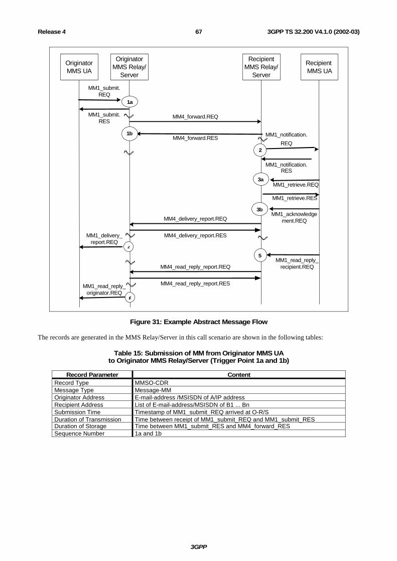
3GPP
3GPP TS 32.200 V4.1.0 (2002-03)67Release 4
OriginatorMMS UA
RecipientMMS Relay/
Server
RecipientMMS UA
MM1_submit.REQ
MM4_forward.REQ
MM1_notification.
REQ
MM1_notification.RES
MM4_forward.RES
MM1_retrieve.REQ
MM1_retrieve.RES
MM1_acknowledgement.REQ
MM4_read_reply_report.REQ
MM1_read_reply_originator.REQ
MM1_submit.RES
OriginatorMMS Relay/
Server
MM4_delivery_report.REQ
MM1_delivery_report.REQ
MM1_read_reply_recipient.REQ
MM4_delivery_report.RES
MM4_read_reply_report.RES
1a
1b
3b
3a
2
4
5
6
Figure 31: Example Abstract Message Flow
The records are generated in the MMS Relay/Server in this call scenario are shown in the following tables:
Table 15: Submission of MM from Originator MMS UA to Originator MMS Relay/Server (Trigger Point 1a and 1b)
Record Parameter Content Record Type MMSO-CDR Message Type Message-MM Originator Address E-mail-address /MSISDN of A/IP address Recipient Address List of E-mail-address/MSISDN of B1 ... Bn Submission Time Timestamp of MM1_submit_REQ arrived at O-R/S Duration of Transmission Time between receipt of MM1_submit_REQ and MM1_submit_RES Duration of Storage Time between MM1_submit_RES and MM4_forward_RES Sequence Number 1a and 1b

3GPP
3GPP TS 32.200 V4.1.0 (2002-03)68Release 4
Table 16: MM Notification from Recipient MMS Relay/Server to Recipient MMS UA (Trigger Point 2)
Record Parameter Content Record Type MMSR-CDR Message Type Notification Originator Address E-mail-address /MSISDN of A/IP address Recipient Address E-mail-address/MSISDN of B Delivery Time Timestamp at MM1_notification_REQ at R-R/S Duration of Transmission Not Applicable Duration of Storage Not Available Sequence Number Not Applicable
Table 17: Acknowledgement of MM retrieval from Recipient MMS UA to Recipient MMS Relay/Server (Trigger Points 3a and 3b)
Record Parameter Content Record Type MMSR-CDR Message Type Message-MM Originator Address E-mail-address /MSISDN of A/IP address Recipient Address E-mail-address/MSISDN of B Delivery Time Timestamp of MM1_retrieve_REQ arrived at O-R/S Duration of Transmission Time between receipt of MM1_submit_REQ and
MM1_acknowledgement_REQ, only applicable if acknowledgement was requested
Duration of Storage Time between MM4_forward_RES and MM1_retrieve_RES Sequence Number 3a and 3b
Table 18: Delivery Report to Originator MMS UA (Trigger Point 4)
Record Parameter Content Record Type MMSR-CDR Message Type Delivery-Report Originator Address E-mail-address /MSISDN of B/IP address Recipient Address E-mail-address/MSISDN of A Delivery Time Timestamp of MM1_delivery_report_REQ at O-R/S Duration of Transmission Not Available Duration of Storage Not Available Sequence Number Not Applicable
Table 19: Read Reply Information from Recipient MMS UA to Recipient MMS Relay/Server (Trigger Point 5)
Record Parameter Content Record Type MMSO-CDR Message Type Read-reply Originator Address E-mail-address /MSISDN of B/IP address Recipient Address E-mail-address/MSISDN of A Submission Time Timestamp of MM1_read_reply_recipient_REQ arrived at R-R/S Duration of Transmission Not Available Duration of Storage Not Available Sequence Number Not Applicable

3GPP
3GPP TS 32.200 V4.1.0 (2002-03)69Release 4
Table 20: Read Replay Report to Originator MMS UA (Trigger Point 6)
Record Parameter Content Record Type MMSR-CDR Message Type Read-reply Originator Address E-mail-address /MSISDN of B/IP address Recipient Address E-mail-address/MSISDN of A Delivery Time Timestamp of MM1_read_reply_originator_REQ at O-R/S Duration of Transmission Not Available Duration of Storage Not Available Sequence Number Not Applicable

3GPP
3GPP TS 32.200 V4.1.0 (2002-03)70Release 4
Annex A (informative): Change history
Change history Date TSG # TSG Doc. CR Rev Subject/Comment Old New
Jun 2001 S_12 SP-010236 -- -- Submitted to TSG SA #12 for Information 1.0.0 1.0.1 Sep 2001 S_13 SP-010464 -- -- Submitted to TSG SA #13 for Approval 2.0.0 4.0.0 Mar 2002 S_15 SP-020016 001 -- Alignment of terminology with 23.140 (MMS) 4.0.0 4.1.0 Mar 2002 S_15 SP-020016 002 -- Corrections on CAMEL D-CSI trigger function 4.0.0 4.1.0 Mar 2002 S_15 SP-020016 003 -- Correction of interface descriptions and terminology 4.0.0 4.1.0