ts-3ga-32.403(rel5)v5.1.0 telecommunication … management; performance management (pm); performance...
TRANSCRIPT

TS-3GA-32.403(Rel5)v5.1.0
Telecommunication management; Performance Management (PM);
Performance Measurements - UMTS and combined UMTS/GSM
Nov 26,2002
THE TELECOMMUNICATION TECHNOLOGY COMMITTEE

i
TS-3GA-32.403(Rel5)v5.1.0 Telecommunication management; Performance Management (PM); Performance Measurements - UMTS and combined UMTS/GSM <Remarks>
1. Application level of English description Application level : E2
English description is included in the text and figures of main body, annexes and appendices.
2. Relationship with international recommendations and standards This standard is standardized based on the Technical Specification 32.403(Version 5.1.0) approved by 3gpp.
3. Departures from international recommendations
Changes to original standard
Standards referred to in the original standard, which are replaced by TTC standards.
Standards referred to in the original standard should be replaced by derived TTC standards.
4. IPR Status of “Confirmation of IPR Licensing Condition” submitted is provided in the TTC web site.
5. Technical Committee
Technical Committee 6

3GPP TS 32.403 V5.1.0 (2002-09)Technical Specification
3rd Generation Partnership Project;Technical Specification Group Services and System Aspects;
Telecommunication management;Performance Management (PM);
Performance Measurements - UMTS and combined UMTS/GSM(Release 5)
GLOBAL SYSTEM FOR MOBILE COMMUNICATIONS
R
The present document has been developed within the 3rd Generation Partnership Project (3GPP TM) and may be further elaborated for the purposes of 3GPP. The present document has not been subject to any approval process by the 3GPP Organizational Partners and shall not be implemented. This Specification is provided for future development work within 3GPP only. The Organizational Partners accept no liability for any use of this Specification.Specifications and reports for implementation of the 3GPP TM system should be obtained via the 3GPP Organizational Partners' Publications Offices.

3GPP
3GPP TS 32.403 V5.1.0 (2002-09)2Release 5
Keywords UMTS, management
3GPP
Postal address
3GPP support office address 650 Route des Lucioles - Sophia Antipolis
Valbonne - FRANCE Tel.: +33 4 92 94 42 00 Fax: +33 4 93 65 47 16
Internet http://www.3gpp.org
Copyright Notification
No part may be reproduced except as authorized by written permission. The copyright and the foregoing restriction extend to reproduction in all media.
© 2002, 3GPP Organizational Partners (ARIB, CWTS, ETSI, T1, TTA, TTC).
All rights reserved.

3GPP
3GPP TS 32.403 V5.1.0 (2002-09)3Release 5
Contents Foreword ..........................................................................................................................................................10 Introduction ......................................................................................................................................................10 1 Scope ......................................................................................................................................................11 2 References ..............................................................................................................................................11 3 Definitions and abbreviations.................................................................................................................12 3.1 Definitions............................................................................................................................................................. 12 3.2 Abbreviations ........................................................................................................................................................ 14 3.3 Measurement definition template .......................................................................................................................... 15 3.4 Definition of private Object Classes...................................................................................................................... 17 3.4.1 Routing Area.................................................................................................................................................... 17 3.5 Management of per cause measurements .............................................................................................................. 18 4 Measurements related to the RNC .........................................................................................................18 4.1 RAB management ................................................................................................................................................. 18 4.1.1 Overview.......................................................................................................................................................... 18 4.1.1.1 Measurements are based on the success and failure of procedures.................................................................. 18 4.1.1.2 Combination of Traffic Class and Core Network domains.............................................................................. 18 4.1.1.3 Considered Radio Access Bearer management procedures ............................................................................. 18 4.1.2 RAB assignment for CS domain..................................................................................................................... 19 4.1.1.1 Measurements are based on the success and failure of procedures.................................................................. 19 4.1.1.2 Combination of Traffic Class and Core Network domains.............................................................................. 19 4.1.1.3 Considered Radio Access Bearer management procedures ............................................................................. 20 4.1.2 RAB assignment for CS domain..................................................................................................................... 20 4.1.2.1 Attempted RAB establishments for CS domain............................................................................................... 20 4.1.2.2 Successful RAB establishments without queuing for CS domain ................................................................... 21 4.1.2.3 Failed RAB establishments without queuing for CS domain .......................................................................... 21 4.1.2.4 Successful RAB establishments with queuing for CS domain......................................................................... 22 4.1.2.5 Failed RAB establishments with queuing for CS domain................................................................................ 22 4.1.3 RAB assignment for PS domain ..................................................................................................................... 23 4.1.3.1 Attempted RAB establishments for PS domain ............................................................................................... 23 4.1.3.2 Successful RAB establishments without queuing for PS domain.................................................................... 23 4.1.3.3 Failed RAB establishments without queuing for PS domain........................................................................... 23 4.1.3.4 Successful RAB establishments with queuing for PS domain......................................................................... 24 4.1.3.5 Failed RAB establishments with queuing for PS domain ................................................................................ 24 4.1.4 RAB setup time............................................................................................................................................... 25 4.1.4.1 RAB CS connection set-up time (Mean) ......................................................................................................... 25 4.1.4.2 RAB CS connection set-up time (Maximum).................................................................................................. 25 4.1.4.3 RAB PS connection set-up time (Mean).......................................................................................................... 25 4.1.4.4 RAB PS connection set-up time (Maximum) .................................................................................................. 26 4.1.5 RAB release ..................................................................................................................................................... 26 4.1.5.1 RAB releases for CS domain ........................................................................................................................... 26 4.1.5.2 RAB releases for PS domain............................................................................................................................ 27 4.2 Void....................................................................................................................................................................... 27 4.3 Signalling connection establishment ..................................................................................................................... 27 4.3.1 Attempted signalling connection establishments for CS domain..................................................................... 27 4.3.2 Attempted signalling connection establishments for PS domain ..................................................................... 27 4.4 RRC connection establishment.............................................................................................................................. 28 4.4.1 RRC connection establishments ...................................................................................................................... 28 4.4.1.1 Attempted RRC connection establishments..................................................................................................... 28 4.4.1.2 Failed RRC connection establishments............................................................................................................ 28 4.4.1.3 Successful RRC connection establishments .................................................................................................... 29 4.4.2 RRC connection establishment setup time....................................................................................................... 29 4.4.2.1 RRC connection set-up time (Mean) ............................................................................................................... 29 4.4.2.2 RRC connection set-up time (Max) ................................................................................................................. 30 4.5 RRC connection re-establishment ......................................................................................................................... 31

3GPP
3GPP TS 32.403 V5.1.0 (2002-09)4Release 5
4.5.1 Attempted RRC re-establishments................................................................................................................... 31 4.5.2 Failed RRC re-establishments.......................................................................................................................... 31 4.5.3 Successful RRC re-establishments .................................................................................................................. 31 4.6 RRC connection release ........................................................................................................................................ 32 4.6.1 Attempted RRC connection releases on DCCH............................................................................................... 32 4.6.2 Attempted RRC connection releases on CCCH............................................................................................... 32 4.7 RLC connection..................................................................................................................................................... 33 4.7.1 Number of RLC blocks sent (per Mode) ......................................................................................................... 33 4.7.2 Number of RLC blocks Received (per Mode) ................................................................................................. 33 4.7.3 Discarded RLC blocks by RNC....................................................................................................................... 33 4.7.4 Number of Retransmitted RLC blocks in Acknowledge Mode ....................................................................... 34 4.8 Soft handover ........................................................................................................................................................ 34 4.8.1 Radio link additions to active link set (UE side).............................................................................................. 34 4.8.1.1 Attempted radio link additions to active link set (UE side) ............................................................................. 34 4.8.1.2 Successful radio link additions to active link set (UE side) ............................................................................. 34 4.8.1.3 Failed radio link additions to active link set (UE side) .................................................................................... 35 4.8.2 Radio link deletions from active link set (UE side) ......................................................................................... 35 4.8.2.1 Attempted radio link deletions from active link set (UE side)......................................................................... 35 4.8.2.2 Successful radio link deletions from active link set (UE side)......................................................................... 36 4.9 Radio link addition procedure (UTRAN side)....................................................................................................... 36 4.9.1 Radio link additions (UTRAN side) ................................................................................................................ 36 4.9.1.1 Attempted radio link additions (UTRAN side)................................................................................................ 36 4.9.1.2 Successful radio link additions (UTRAN side)................................................................................................ 37 4.9.1.3 Failed radio link additions (UTRAN side)....................................................................................................... 37 4.9.2 Radio link deletions (UTRAN side)................................................................................................................. 38 4.9.2.1 Attempted radio link deletions (UTRAN side) ................................................................................................ 38 4.9.2.2 Successful radio link deletions (UTRAN side)................................................................................................ 38 4.10 Hard handover ................................................................................................................................................. 39 4.10.1 Outgoing intra-cell hard handovers ................................................................................................................. 39 4.10.1.1 Attempted outgoing intra-cell hard handovers ........................................................................................... 39 4.10.1.2 Successful outgoing intra-cell hard handovers........................................................................................... 39 4.10.1.3 Failed outgoing intra-cell hard handovers.................................................................................................. 39 4.10.2 Outgoing intra-NodeB hard handovers ............................................................................................................ 40 4.10.2.1 Attempted outgoing intra-NodeB hard handovers...................................................................................... 40 4.10.2.2 Successful outgoing intra-NodeB hard handovers ..................................................................................... 40 4.10.2.3 Failed outgoing intra-NodeB hard handovers ............................................................................................ 41 4.10.3 Outgoing inter-NodeB, intra-RNC hard handovers ......................................................................................... 41 4.10.3.1 Attempted outgoing inter-NodeB, intra-RNC hard handovers................................................................... 41 4.10.3.2 Successful outgoing inter-NodeB, intra-RNC hard handovers................................................................... 41 4.10.3.3 Failed outgoing inter-NodeB, intra-RNC hard handovers.......................................................................... 42 4.10.4 Outgoing inter-RNC hard handovers via Iur.................................................................................................... 42 4.10.4.1 Attempted outgoing inter-RNC hard handovers via Iur ............................................................................. 42 4.10.4.2 Successful outgoing inter-RNC hard handovers via Iur ............................................................................. 43 4.10.4.3 Failed outgoing inter-RNC hard handovers via Iur .................................................................................... 43 4.10.5 Relocation preparation for outgoing inter-RNC hard handovers switching in the CN .................................... 43 4.10.5.1 Attempted relocation preparation for outgoing inter-RNC hard handovers switching in the CN .............. 43 4.10.5.2 Successful relocation preparation for outgoing inter-RNC hard handovers switching in the CN.............. 44 4.10.5.3 Failed relocation preparation for outgoing inter-RNC hard handovers switching in the CN ..................... 44 4.10.6 Outgoing inter-RNC hard handovers switching in the CN .............................................................................. 45 4.10.6.1 Attempted outgoing inter-RNC hard handovers switching in the CN........................................................ 45 4.10.6.2 Successful outgoing inter-RNC hard handovers switching in the CN........................................................ 45 4.10.6.3 Failed outgoing inter-RNC hard handovers switching in the CN............................................................... 45 4.11 Relocation ........................................................................................................................................................ 46 4.11.1 Relocations preparations.................................................................................................................................. 46 4.11.1.1 Attempted relocations preparations............................................................................................................ 46 4.11.1.2 Successful relocation preparations ............................................................................................................. 46 4.11.1.3 Failed relocation preparations .................................................................................................................... 46 4.11.2 Relocations ...................................................................................................................................................... 47 4.11.2.1 Successful relocations ................................................................................................................................ 47 4.12 Circuit switched inter-RAT handover.............................................................................................................. 47 4.12.1 Relocation preparation for outgoing circuit switched inter-RAT handovers ................................................... 47 4.12.1.1 Attempted relocation preparation for outgoing circuit switched inter-RAT handovers ............................. 47

3GPP
3GPP TS 32.403 V5.1.0 (2002-09)5Release 5
4.12.1.2 Successful relocation preparation for outgoing circuit switched inter-RAT handovers............................. 48 4.12.1.3 Failed relocation preparation for outgoing circuit switched inter-RAT handovers.................................... 48 4.12.2 Outgoing circuit switched inter-RAT handovers ............................................................................................. 48 4.12.2.1 Attempted outgoing circuit switched inter-RAT handovers....................................................................... 48 4.12.2.2 Successful outgoing circuit switched inter-RAT handovers ...................................................................... 49 4.12.2.3 Failed outgoing circuit switched inter-RAT handovers ............................................................................. 49 4.12.3 Incoming circuit switched inter-RAT handovers............................................................................................. 49 4.12.3.1 Attempted incoming circuit switched inter-RAT handovers...................................................................... 50 4.12.3.2 Successful incoming circuit switched inter-RAT handovers...................................................................... 50 4.12.3.3 Failed incoming circuit switched inter-RAT handovers............................................................................. 50 4.13 Packet switched inter-RAT handover .............................................................................................................. 51 4.13.1 Outgoing packet switched inter-RAT handovers, UTRAN controlled ............................................................ 51 4.13.1.1 Attempted outgoing packet switched inter-RAT handovers, UTRAN controlled...................................... 51 4.13.1.2 Successful outgoing packet switched inter-RAT handovers, UTRAN controlled ..................................... 51 4.13.1.3 Failed outgoing packet switched inter-RAT handovers UTRAN controlled.............................................. 51 4.13.2 Outgoing packet switched inter-RAT handovers, UE controlled..................................................................... 52 4.13.2.1 Successful outgoing packet switched inter-RAT handovers, UE controlled.............................................. 52 5 Measurements related to the SGSN .......................................................................................................52 5.1 Mobility Management ........................................................................................................................................... 52 5.1.1 Attempted GPRS attach procedures................................................................................................................. 52 5.1.2 Successful GPRS attach procedures ................................................................................................................ 53 5.1.3 Attempted intra-SGSN Routing Area update procedures ................................................................................ 53 5.1.4 Successful intra-SGSN Routing Area update procedures ................................................................................ 53 5.1.5 Attempted GPRS detach procedures initiated by MS ...................................................................................... 54 5.1.6 Attempted GPRS detach procedures initiated by SGSN.................................................................................. 54 5.1.7 Attempted inter-SGSN Routing Area update procedures ................................................................................ 55 5.1.8 Successful inter-SGSN Routing Area update procedures ................................................................................ 55 5.1.9 Attempted GPRS attach procedures with IMSI already attached .................................................................... 55 5.1.10 Successful GPRS attach procedures with IMSI already attached .................................................................... 56 5.1.11 Attempted IMSI detach procedures initiated by MS........................................................................................ 56 5.1.12 Attempted combined GPRS/IMSI attach procedures ...................................................................................... 57 5.1.13 Successful combined GPRS/IMSI attach procedures ...................................................................................... 57 5.1.14 Attempted combined GPRS/IMSI detach procedures initiated by MS............................................................ 57 5.1.15 Successful GPRS detach procedures initiated by SGSN ................................................................................. 58 5.1.16 Attempted combined RA/LA intra-SGSN Routing Area update procedures................................................... 58 5.1.17 Attempted "combined RA/LA with IMSI Attach" intra-SGSN Routing Area update procedures .................. 59 5.1.18 Successful combined RA/LA intra-SGSN Routing Area update procedures .................................................. 59 5.1.19 Attempted combined RA/LA inter-SGSN Routing Area update procedures................................................... 59 5.1.20 Attempted "combined RA/LA with IMSI Attach" inter-SGSN Routing Area update procedures .................. 60 5.1.21 Successful combined RA/LA inter-SGSN Routing Area update procedures .................................................. 60 5.1.22 Number of received invalid P-TMSI's during detach ...................................................................................... 61 5.1.23 Attempted GSM PS paging procedures ........................................................................................................... 61 5.1.24 Attempted UMTS PS paging procedures......................................................................................................... 61 5.1.25 Attempted PS paging procedures with unknown access type .......................................................................... 62 5.1.26 Number of PS paging message sends from 2G-SGSN to the MS.................................................................... 62 5.1.27 Number of PS paging message sends from 3G-SGSN to the MS.................................................................... 62 5.1.28 Successful GSM PS paging procedures ........................................................................................................... 63 5.1.29 Successful UMTS PS paging procedures......................................................................................................... 63 5.1.30 Number of subscribers in PMM-IDLE state .................................................................................................... 63 5.1.31 Number of subscribers in PMM-CONNECTED state ..................................................................................... 64 5.1.32 Number of attached subscribers....................................................................................................................... 64 5.1.33 Number of home subscribers ........................................................................................................................... 64 5.1.34 Number of visiting national subscribers .......................................................................................................... 65 5.1.35 Number of visiting foreign subscribers............................................................................................................ 65 5.1.36 Mean number of attached subscribers.............................................................................................................. 66 5.1.37 Mean Number of home subscribers ................................................................................................................. 66 5.1.38 Mean Number of visiting national subscribers ................................................................................................ 66 5.1.39 Mean Number of visiting foreign subscribers.................................................................................................. 67 5.1.40 Number of CAMEL subscribers ...................................................................................................................... 67 5.1.41 Mean Number of CAMEL subscribers ............................................................................................................ 68

3GPP
3GPP TS 32.403 V5.1.0 (2002-09)6Release 5
5.1.42 Attempted InsertSubscriberData requests received from a HLR during GPRS Update Location procedure.................................................................................................................................................... 68
5.1.43 Attempted GPRS Update Locations sent to the HLR ...................................................................................... 68 5.1.44 Successful GPRS Update Locations sent to the HLR...................................................................................... 69 5.1.45 Attempted CancelLocation requests received from an HLR-operator, in case of a HLR-initiated Detach ..... 69 5.1.46 Attempted CancelLocation requests received from a HLR due to a SGSN-change (previous SGSN)............ 69 5.1.47 Attempted Reset requests received from a HLR due to an HLR restart, indicating that a failure occurred..... 70 5.2 Subscriber Management ........................................................................................................................................ 70 5.2.1 Attempted Insert Subscriber Data requests received from a HLR due to an HLR-operator intervention........ 70 5.2.2 Attempted Delete Subscriber Data requests received from a HLR due to an HLR-operator intervention....... 70 5.3 SRNS Relocation................................................................................................................................................... 71 5.3.1 Attempted intra/inter 3G-SGSN SRNS Relocation ......................................................................................... 71 5.3.2 Successful intra 3G-SGSN SRNS Relocation.................................................................................................. 71 5.3.3 Failed intra 3G-SGSN SRNS Relocation, due to internal reasons................................................................... 71 5.3.4 Failed intra 3G-SGSN SRNS Relocation, due to external reasons .................................................................. 72 5.3.5 Attempted inter 3G-SGSN SRNS Relocation.................................................................................................. 72 5.3.6 Successful inter 3G-SGSN SRNS Relocation, counted in the old 3G-SGSN.................................................. 72 5.3.7 Failed inter 3G-SGSN SRNS Relocation, due to internal reasons................................................................... 73 5.3.8 Failed inter 3G-SGSN SRNS Relocation, due to external reasons .................................................................. 73 5.3.9 Attempted inter 3G-SGSN SRNS Relocation, counted in the new 3G-SGSN ................................................ 73 5.3.10 Successful Inter 3G-SGSN SRNS Relocation, counted in the new 3G-SGSN................................................ 74 5.4 Security.................................................................................................................................................................. 74 5.4.1 Attempted P-TMSI reallocation procedures .................................................................................................... 74 5.4.2 Successful P-TMSI reallocation procedures .................................................................................................... 74 5.4.3 Attempted Identity Request procedures initiated by this SGSN ...................................................................... 75 5.4.4 Successful completed Identity Request procedures initiated by this SGSN .................................................... 75 5.4.5 Attempted identification information requests sent to a partner (previous) SGSN for subscribers
registering afresh in this SGSN.................................................................................................................. 76 5.4.6 Successful replied identification information requests that were sent to a partner (previous) SGSN.............. 76 5.4.7 Attempted Identity Requests sent to the MS.................................................................................................... 76 5.4.8 Successful replied Identity Requests from the MS .......................................................................................... 77 5.4.9 Attempted authentication procedures that are started within this SGSN area for a subscriber using a SIM.... 77 5.4.10 Successful authentication procedures within this SGSN area, for a subscriber using a SIM........................... 78 5.4.11 Attempted authentication procedures that are started within this SGSN area for a subscriber using a
USIM.......................................................................................................................................................... 78 5.4.12 Successful authentication procedures within this SGSN area, for a subscriber using a USIM........................ 78 5.4.13 Received ciphering and Authentication failures within this SGSN area.......................................................... 79 5.4.14 Attempted identification information requests that were received from a partner (new) SGSN for
subscribers de-registering from this SGSN ................................................................................................ 79 5.4.15 Successfully replied identification information requests that were received from a partner (new) SGSN ...... 80 5.4.16 Attempted SGSN context requests sent to a partner (previous) SGSN for subscribers registering afresh
in this SGSN............................................................................................................................................... 80 5.4.17 Successfully replied SGSN context requests that were sent to a partner (previous) SGSN............................. 81 5.4.18 Attempted SGSN context requests received from a partner (new) SGSN for a subscriber de-registering
from this SGSN.......................................................................................................................................... 81 5.4.19 Successfully replied SGSN context requests received from a partner (new) SGSN........................................ 81 5.4.20 Number of P-TMSI - IMSI correlation failures (User Identity Confidentiality (TS 23.060)) ......................... 82 5.4.21 Attempted security mode control procedures started by the SGSN................................................................. 82 5.4.22 Successful security mode procedures .............................................................................................................. 82 5.4.23 Attempted ciphering procedures started by the SGSN..................................................................................... 83 5.4.24 Successful ciphering procedures started by the SGSN .................................................................................... 83 5.4.25 Attempted MAP V1 requests for authentication sets, sent to the HLR by SGSN............................................ 83 5.4.26 Successful MAP V1 requests for authentication sets that were sent to the HLR............................................. 84 5.4.27 Number of empty responses to the MAP V1 request for authentication sets that were sent to the HLR......... 84 5.4.28 Attempted MAP V3 requests for Authentication sets sent to the HLR by SGSN............................................ 84 5.4.29 Successful MAP V3 requests for authentication sets that were sent to the HLR............................................. 85 5.4.30 Number of empty responses to the MAP V3 request for authentication sets that were sent to the HLR......... 85 5.5 SMS....................................................................................................................................................................... 85 5.5.1 SMS in the CS domain (MSC)......................................................................................................................... 85 5.5.1.1 Attempted CS SMS mobile originating ........................................................................................................... 85 5.5.1.2 Successful CS SMS mobile originating ........................................................................................................... 86 5.5.1.3 Attempted CS SMS mobile terminating .......................................................................................................... 86

3GPP
3GPP TS 32.403 V5.1.0 (2002-09)7Release 5
5.5.1.4 Successful CS SMS mobile terminating .......................................................................................................... 86 5.5.1.5 Attempted CS ms-Present ................................................................................................................................ 87 5.5.1.6 Attempted CS "memory available".................................................................................................................. 87 5.5.1.7 Successful CS ms-Present................................................................................................................................ 88 5.5.1.8 Successful CS "memory available".................................................................................................................. 88 5.5.2 SMS in the PS domain (SGSN) ....................................................................................................................... 88 5.5.2.1 Attempted PS SMS mobile originating............................................................................................................ 89 5.5.2.2 Successful PS SMS mobile originating ........................................................................................................... 89 5.5.2.3 Attempted PS SMS mobile terminating........................................................................................................... 89 5.5.2.4 Successful PS SMS mobile terminating........................................................................................................... 90 5.5.2.5 Attempted PS ms-Present ................................................................................................................................ 90 5.5.2.6 Attempted PS "memory available" .................................................................................................................. 90 5.5.2.7 Successful PS ms-Present ................................................................................................................................ 91 5.5.2.8 Successful PS "memory available" .................................................................................................................. 91 5.5.3 SMS in the CS/PS domain (MSC/SGSN)........................................................................................................ 92 5.5.3.1 Attempted SMS mobile originating ................................................................................................................. 92 5.5.3.2 Successful SMS mobile originating................................................................................................................. 92 5.5.3.3 Attempted SMS mobile terminating ................................................................................................................ 93 5.5.3.4 Successful SMS mobile terminating................................................................................................................ 93 5.5.3.5 Attempted ms-Present...................................................................................................................................... 93 5.5.3.6 Attempted "memory available"........................................................................................................................ 94 5.5.3.7 Successful ms-Present...................................................................................................................................... 94 5.5.3.8 Successful "memory available" ....................................................................................................................... 95 5.6 Session Management ............................................................................................................................................. 95 5.6.1 Attempted PDP context activation procedures initiated by MS....................................................................... 95 5.6.2 Attempted dynamic PDP context activation procedures initiated by MS ........................................................ 95 5.6.3 Successful PDP context activation procedures initiated by MS....................................................................... 96 5.6.4 Successful dynamic PDP context activation procedures initiated by MS........................................................ 96 5.6.5 Mean number of activated PDP contexts ......................................................................................................... 97 5.6.6 Attempted PDP context deactivation procedures initiated by the MS ............................................................. 97 5.6.7 Successful PDP context deactivation procedures initiated by the MS............................................................. 97 5.6.8 Number of active PDP context ........................................................................................................................ 98 5.6.9 Number of mobile subscribers with activated PDP context (i.e. subscribers that can send/receive GPRS
packet data) ................................................................................................................................................ 98 5.6.10 Mean number of subscribers that have an activated PDP context (i.e. subscribers that can send/receive
GPRS packet data) ..................................................................................................................................... 99 5.6.11 Attempted PDP context deactivation procedures initiated by the GGSN ........................................................ 99 5.6.12 Successful PDP context deactivation procedures initiated by the GGSN...................................................... 100 5.6.13 Attempted PDP context deactivation procedures initiated by the SGSN....................................................... 100 5.6.14 Successful PDP context deactivations initiated by the SGSN ....................................................................... 100 5.6.15 Attempted SGSN-Initiated PDP context update procedures.......................................................................... 101 5.6.16 Successful SGSN-Initiated PDP context update procedures.......................................................................... 101 5.6.17 Attempted GGSN-Initiated PDP context update procedures ......................................................................... 102 5.6.18 Successful GGSN-Initiated PDP context update procedures ......................................................................... 102 5.6.19 Attempted SGSN-Initiated PDP context modifications procedures............................................................... 102 5.6.20 Successfully SGSN-Initiated PDP context modifications procedures ........................................................... 103 5.6.21 Attempted MS-Initiated PDP context modifications procedures ................................................................... 103 5.6.22 Successfully MS-Initiated PDP context modifications procedures................................................................ 104 5.6.23 Attempted Secondary PDP context activation procedures............................................................................. 104 5.6.24 Successful Secondary PDP context activations ............................................................................................. 104 5.6.25 Failed PDP context activation procedures initiated by MS............................................................................ 105 5.6.26 Failed PDP context activation procedures initiated by Network ................................................................... 105 5.6.276 Abnormal PDP context Deactivation procedures .......................................................................................... 106 5.6.28 PDP Context set-up time, initiated by MS (Mean) ........................................................................................ 106 5.6.29 PDP Context set-up time, initiated by MS (Max) .......................................................................................... 106 5.6.30 PDP Context set-up time, initiated by Network (Mean) ................................................................................ 107 5.6.31 PDP Context set-up time, initiated by Network (Max).................................................................................. 107 5.7 CAMEL Measurements....................................................................................................................................... 108 5.7.1 Attempted CAMEL dialogues ....................................................................................................................... 108 5.7.2 Failed CAMEL dialogues, aborted locally by gprsSSF ................................................................................. 108 5.7.3 Failed CAMEL dialogues, error or reject from gsmSCF............................................................................... 109 5.8 UMTS-GSM Intersystem Change ....................................................................................................................... 109

3GPP
3GPP TS 32.403 V5.1.0 (2002-09)8Release 5
5.8.1 Attempted intra SGSN inter system changes from UMTS to GSM............................................................... 109 5.8.2 Successful intra SGSN inter system changes from UMTS to GSM .............................................................. 109 5.8.3 Failed intra SGSN inter system changes UMTS to GSM RAU, due to internal reasons............................... 110 5.8.4 Failed intra SGSN inter system changes UMTS to GSM RAU, due to external reasons .............................. 110 5.8.5 Attempted intra SGSN inter system changes from GSM to UMTS............................................................... 110 5.8.6 Successful intra SGSN inter system changes from GSM to UMTS .............................................................. 110 5.8.7 Failed intra SGSN inter system changes GSM to UMTS RAU, due to internal reasons............................... 111 5.8.8 Failed intra SGSN inter system changes GSM to UMTS RAU, due to external reasons .............................. 111 5.9 UMTS GTP Measurements ................................................................................................................................. 111 5.9.1 GTP-U Iu ....................................................................................................................................................... 111 5.9.1.1 Number of outgoing GTP data packets on the Iu interface............................................................................ 111 5.9.1.2 Number of incoming GTP data packets on the Iu interface........................................................................... 112 5.9.1.3 Number of octets of outgoing GTP data packets on the Iu interface ............................................................. 112 5.9.1.4 Number of octets of incoming GTP data packets on the Iu interface ............................................................ 112 5.9.2 GTP Gn.......................................................................................................................................................... 113 5.9.2.1 Number of outgoing GTP data packets on the Gn interface .......................................................................... 113 5.9.2.2 Number of incoming GTP data packets on the Gn interface ......................................................................... 113 5.9.2.3 Number of octets of outgoing GTP data packets on the Gn interface............................................................ 113 5.9.2.4 Number of octets of incoming GTP data packets on the Gn interface........................................................... 114 5.9.2.5 Number of outgoing GTP signalling packets on the Gn interface ................................................................. 114 5.9.2.6 Number of incoming GTP signalling packets on the Gn interface ................................................................ 115 5.9.2.7 Number of octets of outgoing GTP signalling packets on the Gn interface................................................... 115 5.9.2.8 Number of octets of incoming GTP signalling packets on the Gn interface.................................................. 115 5.10 UMTS Bearer Service.................................................................................................................................... 116 5.10.1 UMTS Bearer Service CS time to register (Mean) ........................................................................................ 116 5.10.2 UMTS Bearer Service CS time to register (Max).......................................................................................... 116 5.10.3 UMTS Bearer Service PS time to register (Mean)......................................................................................... 117 5.10.4 UMTS Bearer Service PS time to register (Max) .......................................................................................... 117 5.10.5 UMTS Bearer Service time to establish Communications Management (CM) radio access connectivity
(Mean)...................................................................................................................................................... 117 5.10.6 UMTS Bearer Service time to establish Communications Management (CM) radio access connectivity
(Max)........................................................................................................................................................ 118 6 Measurements related to the GGSN.....................................................................................................118 6.1 Session Management ........................................................................................................................................... 118 6.1.1 Session establishments................................................................................................................................... 118 6.1.1.1 Attempted session establishments.................................................................................................................. 119 6.1.1.2 Successful session establishments ................................................................................................................. 120 6.1.1.3 Failed session establishments ........................................................................................................................ 120 6.1.2 Network-initiated session establishments ...................................................................................................... 121 6.1.2.1 Number of routing information requests for network-initiated session establishment attempts .................... 121 6.1.2.2 Number of routing information successful responses for network-initiated session establishment
attempts .............................................................................................................................................. 122 6.1.2.3 Attempted Network-initiated session establishments .................................................................................... 122 6.1.2.4 Failed Network-initiated session establishments - failures occurred before sending PDP context
activation request to the MS ............................................................................................................... 122 6.1.2.5 Failed Network-initiated session establishments - failures occurred after sending PDP context activation
request to the MS................................................................................................................................ 123 6.1.3 Number of subscribers ................................................................................................................................... 123 6.1.3.1 Number of subscribers with an activated PDP context .................................................................................. 123 6.1.3.2 Mean number of subscribers with an activated PDP context......................................................................... 124 6.1.4 Session conclusions ....................................................................................................................................... 124 6.1.4.1 Attempted MS & SGSN-initiated session conclusions .................................................................................. 125 6.1.4.2 Attempted GGSN-initiated session conclusions ............................................................................................ 126 6.1.4.3 Successfully concluded sessions.................................................................................................................... 126 6.2 Per APN measurements....................................................................................................................................... 126 6.2.1 Session establishments................................................................................................................................... 126 6.2.1.1 Attempted session establishments, per APN.................................................................................................. 127 6.2.1.2 Successfully established sessions, per APN .................................................................................................. 128 6.2.1.3 Attempted session establishments with dynamic PDP address allocation required, per APN....................... 128 6.2.1.4 Successfully established sessions with dynamic PDP address allocation required, per APN........................ 128 6.2.1.5 Attempted session establishments with user authentication required, per APN ............................................ 129

3GPP
3GPP TS 32.403 V5.1.0 (2002-09)9Release 5
6.2.1.6 Failed session establishments due to user authentication failure, per APN ................................................... 129 6.2.2 Active sessions............................................................................................................................................... 130 6.2.2.1 Number of simultaneous active sessions, per APN ....................................................................................... 130 6.2.2.2 Peak number of simultaneous active sessions, per APN................................................................................ 130 6.2.2.3 Attempted MS & SGSN-initiated session modifications, per APN............................................................... 131 6.2.2.4 Successfully performed MS & SGSN-initiated session modifications, per APN .......................................... 131 6.2.3 Session conclusions ....................................................................................................................................... 131 6.2.3.1 Attempted MS-initiated session conclusions, per APN ................................................................................. 131 6.2.3.2 Successful MS-initiated session conclusions, per APN................................................................................. 132 6.2.3.3 Attempted GGSN-initiated session conclusions, per APN ............................................................................ 132 6.2.3.4 Successful GGSN-initiated session conclusions, per APN............................................................................ 132 6.3 GTP measurements.............................................................................................................................................. 133 6.3.1 Number of incoming GTP data packets on the Gn interface ......................................................................... 133 6.3.2 Number of outgoing GTP data packets on the Gn interface .......................................................................... 133 6.3.3 Number of discarded GTP data packets......................................................................................................... 134 6.3.4 Number of octets of incoming GTP data packets on the Gn interface........................................................... 134 6.3.5 Number of octets of outgoing GTP data packets on the Gn interface............................................................ 135 6.3.6 Number of incoming GTP signalling packets on the Gn interface ................................................................ 135 6.3.7 Number of outgoing GTP signalling packets on the Gn interface ................................................................. 136 6.3.8 Number of discarded GTP signalling packets................................................................................................ 136 6.3.9 Number of octets of incoming GTP signalling packets on the Gn interface.................................................. 136 6.3.10 Number of octets of outgoing GTP signalling packets on the Gn interface................................................... 137 6.3.11 Number of GTP tunnels on the Gn interface ................................................................................................. 137 6.3.12 Number of GTP tunnels created on the Gn interface ..................................................................................... 138 6.4 GTP' measurements............................................................................................................................................. 138 6.4.1 Attempted CDR information transfers........................................................................................................... 139 6.4.2 Successful CDR information transfers........................................................................................................... 139 6.4.3 Failed CDR information transfers.................................................................................................................. 140 6.5 IP measurements.................................................................................................................................................. 140 6.5.1 Number of incoming IP data packets on the Gi interface .............................................................................. 141 6.5.2 Number of outgoing IP data packets on the Gi interface ............................................................................... 142 6.5.3 Number of IP data packets discarded due to node congestion ....................................................................... 142 6.5.4 Number of octets of incoming IP data packets on the Gi interface................................................................ 142 6.5.5 Number of octets of outgoing IP data packets on the Gi interface................................................................. 143
Annex A (informative): Examples for "(n-1) out of n" approach....................................................144 A.1 Attempt/success/failure procedure measurements ...............................................................................144 A.2 GSM/UMTS combined measurements ................................................................................................144 A.3 Embedded "(n-1) out of n" approaches ................................................................................................145
Annex B (Informative): Top-Down Performance Measurement Definition Process......................146 B.1 Scope of this annex.............................................................................................................................................. 146 B.2 Overview ............................................................................................................................................................. 146 B.3 Measurement User Communities ........................................................................................................................ 147 B.3.1 Network Operator Business Community ....................................................................................................... 147 B.3.2 Network Operator Maintenance Community................................................................................................. 147 B.3.3 Network Operator Traffic Engineering Community...................................................................................... 148 B.3.4 Network Operator Customer Care Community ............................................................................................. 148 B.3.5 Equipment Vendor Performance Modelling Community .............................................................................. 148 B.3.6 Equipment Vendor Development Engineering Community .......................................................................... 148 B.3.7 User Community Conclusion......................................................................................................................... 149 B.4 Enhanced GQM................................................................................................................................................... 149 B.4.1 GQM Methodology........................................................................................................................................ 149 B.4.2 Enhanced GQM (EGQM) Methodology........................................................................................................ 150 B.5 Measurements Life Cycle Process....................................................................................................................... 152 B.6 Conclusion........................................................................................................................................................... 152
Annex C (informative): Change history .............................................................................................154

3GPP
3GPP TS 32.403 V5.1.0 (2002-09)10Release 5
Foreword This Technical Specification has been produced by the 3rd Generation Partnership Project (3GPP).
The present document is part of the 32.400-series covering the 3rd Generation Partnership Project; Technical Specification Group Services and System Aspects; Telecommunication Management; Performance Management (PM), as identified below:
TS 32.401: "Concept and Requirements";
TS 52.402: "Performance Measurements - GSM";
TS 32.403: "Performance Measurements UMTS and combined UMTS/GSM".
The contents of the present document are subject to continuing work within the TSG and may change following formal TSG approval. Should the TSG modify the contents of the present document, it will be re-released by the TSG with an identifying change of release date and an increase in version number as follows:
Version x.y.z
where:
x the first digit:
1 presented to TSG for information;
2 presented to TSG for approval;
3 or greater indicates TSG approved document under change control.
y the second digit is incremented for all changes of substance, i.e. technical enhancements, corrections, updates, etc.
z the third digit is incremented when editorial only changes have been incorporated in the document.
Introduction The present document is part of a set of specifications, which describe the requirements and information model necessary for the standardised Operation, Administration and Maintenance (OA&M) of a multi-vendor 3G-system.
During the lifetime of a 3G network, its logical and physical configuration will undergo changes of varying degrees and frequencies in order to optimise the utilisation of the network resources. These changes will be executed through network configuration management activities and/or network engineering, see TS 32.600 [3].
Many of the activities involved in the daily operation and future network planning of a 3G network require data on which to base decisions. This data refers to the load carried by the network and the grade of service offered. In order to produce this data performance measurements are executed in the NEs, which comprise the network. The data can then be transferred to an external system, e.g. an Operations System (OS) in TMN terminology, for further evaluation. The purpose of the present document is to describe the mechanisms involved in the collection of the data and the definition of the data itself.
Annex B has been added to help in the definition of new performance measurements that can be submitted to 3GPP for potential adoption and inclusion in the present document. Annex B discusses a top-down performance measurement definition methodology that focuses on how the end-user of performance measurements can use the measurements.

3GPP
3GPP TS 32.403 V5.1.0 (2002-09)11Release 5
1 Scope The present document describes the measurements for UMTS and combined UMTS/GSM.
TS 32.401 [12] describes Performance Management concepts and requirements.
The present document is valid for all measurement types provided by an implementation of a UMTS network and combined UMTS/GSM network. These may be measurement types defined within the present document, measurements defined within other standards bodies, or vendor specific measurement types.
Only measurement types that are specific to UMTS or combined UMTS/GSM networks are defined within the present documents. I.e. vendor specific measurement types and measurements related to "external" technologies used in UMTS and combined UMTS/GSM networks, such as ATM or IP, are not covered. Instead, these could be applied as described by the other, "external" standards bodies (e.g. ITU-T or IETF) or according to manufacturer's documentation.
The definition of the standard measurements is intended to result in comparability of measurement data produced in a multi-vendor network, for those measurement types that can be standardised across all vendors' implementations.
The structure of the present document is as follows:
- Header 1: Network Element (e.g. RNC related measurements);
- Header 2: Measurement function (e.g. soft handover measurements);
- Header 3: Measurements.
2 References The following documents contain provisions which, through reference in this text, constitute provisions of the present document.
• References are either specific (identified by date of publication and/or edition number or version number) or non-specific.
• For a specific reference, subsequent revisions do not apply.
• For a non-specific reference, the latest version applies. In the case of a reference to a 3GPP document (including a GSM document), a non-specific reference implicitly refers to the latest version of that document in the same Release as the present document.
[1] 3GPP TS 32.101: "3G Telecom Management: Principles and high level requirements".
[2] 3GPP TS 32.102: "3G Telecom Management architecture".
[3] 3GPP TS 32.600: "Telecommunication Management; Configuration Management; 3G configuration management; Concept and main requirements".
[4] 3GPP TS 25.331: "Radio Resource Control (RRC) protocol specification".
[5] 3GPP TS 25.413: "UTRAN Iu Interface RANAP signalling".
[6] 3GPP TS 25.423: "UTRAN Iur Interface RNSAP signalling".
[7] 3GPP TS 25.433: "UTRAN Iub Interface NBAP signalling".
[8] 3GPP TS 23.107: "Quality of Service (QoS) concept and architecture".
[9] 3GPP TS 32.622: "Telecommunication Management; Configuration Management; Generic network resources IRP: NRM".
[10] 3GPP TS 32.632: "Telecommunication Management; Configuration Management; Core Network Resources IRP: NRM".

3GPP
3GPP TS 32.403 V5.1.0 (2002-09)12Release 5
[11] 3GPP TS 32.642: "Telecommunication Management; Configuration Management; UTRAN network resources IRP: NRM".
[12] 3GPP TS 32.401: "Telecommunication Management; Performance Management (PM); Concept and Requirements".
[13] GSM 12.04: "Digital cellular telecommunications system (Phase 2+); Performance data measurements".
[14] 3GPP TS 52.402: "Telecommunication Management; Performance Management (PM); Performance Measurements - GSM".
[15] 3GPP TS 24.008: "Mobile Radio Interface Layer 3 specification; Core Network Protocols; Stage 3".
[16] GSM 08.18: "Digital cellular telecommunication system (Phase 2); General Packet Radio Service (GPRS); Base Station System (BSS) - Serving GPRS Support Node (SGSN); BSS GPRS Protocol (BSSGP)".
[17] 3GPP TS 23.060: "General Packet Radio Service (GPRS) Service description; Stage 2".
[18] 3GPP TS 29.002: "Mobile Application Part (MAP) specification".
[19] 3GPP TS 29.060: "General Packet Radio Service (GPRS); GPRS Tunnelling Protocol (GTP) across the Gn and Gp interface".
[20] 3GPP TS 24.011: "Point-to-Point (PP) Short Message Service (SMS) support on mobile radio interface".
[21] 3GPP TS 23.003: "Numbering, Addressing and Identification".
[22] Victor R Basili and H. Dieter Rombach: “The TAME project: Towards improvement-oriented software environments”, IEEE Transactions of Software Engineering, Vol. 14, No. 6, June 1988.
[23] Victor R Basili and David M. Weiss: “A Methodology for Collecting Valid Software Engineering Data”, IEEE Transactions of Software Engineering, Vol. SE- 10, No. 6, November 1984.
[24 3GPP TS 25.322: "Radio Link Control (RLC) protocol specification".
3 Definitions and abbreviations
3.1 Definitions For the purposes of the present document, the following terms and definitions apply:
"(n-1) out of n" approach:
- The measurements result values generated by a NE can be obtained in a number of different ways. Therefore, the "(n-1) out of n approach" has been defined in order to avoid redundancy in the measurements.
- The "(n-1) out of n approach" allows a vendor to choose any (n-1) out of the n defined counters for implementation but some choices can offer more detailed information than others. The missing nth value can be calculated in post-processing.
- If multiple measurements are included in one template, then the applicability of the "(n-1) out of n" scenario are mentioned in template item A with the following sentence "The n measurement types defined in item E are subject to the "(n-1) out of n approach"". The item D will specify the measurement result per measurement type specified in template item E.
- If the measurements that are applicable to the "(n-1) out of n" scenario are defined in separate templates, then they will be grouped together into a common clause of the TS, and the applicability of the approach will be mentioned in the clause that groups the measurements.

3GPP
3GPP TS 32.403 V5.1.0 (2002-09)13Release 5
- Examples of measurements which are subject to the "(n-1) out of n" approach are provided in the annex A.
Measurement community
Several measurement communities are defined in the present document to identify the end users of system measurements. Each measurement should be defined to address the needs of at least one of these user communities.
Six communities have been identified so far:
Network Operator’s Business Community
Network Operator’s Maintenance Community
Network Operator’s Traffic Engineering Community
Network Operator’s Customer Care Community
Equipment Vendor’s Performance Modelling Community
Equipment Vendor’s Development Engineering Community
A comprehensive description of measurement communities is provided in Annex B. The user communities names are a composite of the various terms used in the industry and might be subject to modification or refinement in future releases.
Measurement family
The measurement names defined in the present document are all beginning with a prefix containing the measurement family name (e.g. RAB.AttEstabCS.Conv, MM.AttGprsAttach). This family name identifies all measurements which relate to a given functionality and it may be used for measurement administration (see TS 32.401 [12]).
The list of families currently used in the present document is as follows:
- CAM (measurements related to CAMEL)
- GTP (measurements related to GTP)
- HHO (measurements related to Hard Handover)
- IRATHO (measurements related to inter-Radio Access Technology Handover)
- ISYSC (measurements related to GSM/UMTS Intersystem changes)
- MM (measurements related to Mobility Management)
- RAB (measurements related to Radio Access Bearer management)
- RELOC (measurements related to SRNS Relocation)
- RLC (measurements related to Radio Link Control)
- RRC (measurements related to Radio Resource Control)
- SEC (measurements related to Security)
- SHO (measurements related to Soft Handover)
- SIG (measurements related to Signalling)
- SM (measurements related to Session Management)
- SMS (measurements related to Short Message Service)
- SUB (measurements related to Subscriber Management)
- UBS (measurements related to UMTS Bearer Service)

3GPP
3GPP TS 32.403 V5.1.0 (2002-09)14Release 5
3.2 Abbreviations For the purposes of the present document, the following abbreviations apply:
3G 3rd Generation 3GPP 3G Partnership Project ASN.1 Abstract Syntax Notation 1 BER Basic Encoding Rules DTD Document Type Definition EGQM Enhanced Goal, Question, Metric EM (Network) Element Manager FTAM File Transfer Access and Management FTP File Transfer Protocol GQM Goal, Question, Metric IEEE Institute of Electrical and Electronics Engineers, Inc. Itf Interface ITU-T International Telecommunication Union - Telecommunications Standardisation Sector MSC Mobile services Switching Centre NE Network Element NM Network Manager OA&M Operation, Administration and Maintenance OS Operations System (EM, NM) OSI Open Systems Interconnection PM Performance Management QoS Quality of Service RNC Radio Network Controller TFTP Trivial FTP UMTS Universal Mobile Telecommunications System UTRAN UMTS Terrestrial Radio Access Network
You can find below a list of abbreviations used within the measurement types for field E of the measurement template (see subclause 3.3).
Assn Assign(ment,ed) Att Attempt(s,ed) Auth Authentication Bgrd Background Call Call Chg Change Conn Connection Combi Combined CS Circuit switched Ctrl Controlled Conv Conversational Del Deletion Drop Drop(ped) Estab Establish (ed,ment) Fail Fail(ed, ure) HHO Hard Handover HO Handover Inc Incoming Intact Interactive Inter Inter Intra Intra MM Mobility Management Nat National Netw Network NodeB NodeB Oct Octet(s) Out Outgoing Pkt Packet(s) Prep Preparation

3GPP
3GPP TS 32.403 V5.1.0 (2002-09)15Release 5
Proc Procedure PS Packet switched RAB Radio Access Bearer RAT Radio Access Technology ReEstab Re-establish (ed,ment) Rel Released Reloc Relocation Req Request(s,ed) RL Radio Link RNC RNC RRC Radio Resource Control Setup Setup SGSN SGSN SHO Soft Handover Sig Signalling Strm Streaming Sub Subscriber Succ Success(es,ful) UE User Equipment UTRAN UTRAN
3.3 Measurement definition template Following is the template used to describe the measurements contained in this subclause.
C.x.y. Measurement Name (clause header)
This is a descriptive name of the measurement type that is specified as clause C.x.y of the present document.
The measurement name shall be written in lower-case characters except abbreviations (e.g. RNC).
A measurement name can apply to one or more measurements. If the measurement name applies to several measurements then all fields of the template will take this into account.
a) Description
This subclause contains an explanation of the measurement operation.
b) Collection Method
This n contains the form in which this measurement data is obtained:
- CC (Cumulative Counter);
- GAUGE (dynamic variable), used when data being measured can vary up or down during the period of measurement;
- DER (Discrete Event Registration), when data related to a particular event are captured every nth event is registered, where n can be 1 or larger;
- SI (Status Inspection).
c) Condition
This subclause contains the condition which causes the measurement result data to be updated; This will be defined by identifying protocol related trigger events for starting and stopping measurement processes, or updating the current measurement result value. Where it is not possible to give a precise condition, then the conditional circumstances leading to the update are stated.
If a measurement is not available for FDD or TDD, then the measurement description shall contain a statement.
d) Measurement Result (measured value(s), Units)
This subclause contains a description of expected result value(s) (e.g. a single integer value).

3GPP
3GPP TS 32.403 V5.1.0 (2002-09)16Release 5
The definition applies for each measurement result.
e) Measurement Type
This subclause contains a short form of the measurement name specified in the header, which is used to identify the measurement type in the result files.
The measurement names are dotted sequences of items. The sequence of elements identifying a measurement is organised from the general to the particular.
- The first item identifies the measurement family (e.g. HHO, RAB, SMS). Note that this family may also be used for measurement administration purpose.
- The second item identifies the name of the measurement itself.
- Depending on the measurement type, additional items may be present to specify sub-counters (failure causes, traffic classes, min, max, avg, G, U ...). In case of multiple additional items, they are also represented as a dotted sequence of items. When available, the template will describe to which standard it is referring to for these additional items (e.g. cause, traffic class). Otherwise, the additional item semantics must be described in details in the present document. Standardised causes will be a number. (e.g. RRC.ConnEstab.1) but non standardised causes should be a string (e.g. RRC.ConnEstab.NoReply).
It is to be noted that the set of values issued for a measurement does not depend on the associated collection method (CC, SI, Gauge, DER). For instance, a gauge collected counter does not necessarily provide min, max, average values.
The vendor-specific UMTS and combined GSM/UMTS measurement names will all begin with the VS prefix.
In addition, it is recommended that a prefix is added for non-UMTS measurements:
- Q3 for Q3 measurements;
- MIB for IETF measurements (ATM, IP);
- OS for other standards measurements.
NOTE 1: The 3GPP standardised measurements name must not commence with the above prefixes.
Examples of valid measurement names are:
- VS.HO.InterSGSNReject.NoResource;
- HHO.SuccOutIntraCell;
- MM.AttachedSubs.Max;
- RAB.EstabAttCS.Conversational;
- RRC.ConnEstab.Cause where Cause identifies the failure cause.
Abbreviations to be used within measurement types can be found in subclause 3.2 of the present document.
f) Measurement Object Class
This subclause describes the measured object class (e.g. UtranCell, RncFunction, SgsnFunction). The object class used for this purpose shall be in accordance with the Network Resource Model defined in 3GPP TS 32.622 [9], TS 32.632 [10] and TS 32.642 [11].
For object classes currently not defined in CM, the present document defines its own nomenclature (e.g. RA, LAC).

3GPP
3GPP TS 32.403 V5.1.0 (2002-09)17Release 5
NOTE: It is possible to use the same measurement name for a standardized measurement type implemented at a different object class level than the one defined in the Standard. The same measurement type can apply to one or more measurements for which all fields of the measurement template are the same except the clause f) “Measurement Object Class”. For instance, a measurement which uses the same template as a given measurement type but relates to another object class (e.g. UtranCell instead of UtranRelation) shall have the same name.
g) Switching Technology
This subclause contains the Switching domain(s) this measurement is applicable to i.e. Circuit Switched and/or Packet Switched.
h) Generation
The generation determines if it concerns a GSM, UMTS, or combined (GSM+UMTS) measurement.
- GSM: pure GSM measurement; it only counts GSM events. In a combined (GSM+UMTS) NE the count would be exactly the same as in a pure GSM NE. In a pure UMTS NE this counter does not exist;
- UMTS: pure UMTS measurement; it only counts UMTS events. In a combined (GSM+UMTS) NE the count would be exactly the same as in a pure UMTS NE. In a pure GSM NE this counter does not exist;
- GSM/UMTS: measurement applicable to both GSM and UMTS systems; in a combined (GSM+UMTS) NE separate subcounts for GSM and/or UMTS events can be obtained;
- Combined: measurement applicable to combined GSM and UMTS systems, but regardless of whether the measured event occurred on the GSM or UMTS part of the system. This means that in a combined NE only one total (i.e. GSM+UMTS) count is obtained for the measured event.
The above aspects are also reflected in the measurement type name in template item E by adding a "G" to the GSM measurements and "U" to the UMTS measurements.
NOTE 2: The 2G component of a combined 2G/3G equipment may actually choose to implement GSM measurements according to the present document or GSM12.04/TS 52.402, based on GSM standards.
i) Purpose
This optional clause aims at describing who will be using the measurement. It is proposed to indicate in this clause the targetted categories of users based on the measurement user communities described in Annex B.
When available, this clause provides additional information on the interest of the measurement but is however purely indicative.
3.4 Definition of private Object Classes Private Object Classes are Object Classes which are needed for PM purposes, but that are not yet defined by CM.
3.4.1 Routing Area The Object Class Routing Area (RA) is needed to conduct measurements on RA level. For the purpose of the present document, the Routing Area should be encoded in the file format as the concatenation of the MCC, MNC, LAC and the RAC, in decimal notation. See further definition of Routing Area Identification in TS 23.003 [21]. Since LAC is a 2 byte number (00000-65535), 5 characters are needed in the moid PrintableString. Since RAC is a 1 byte number (000-255) 3 characters are needed in the moid PrintableString. MCC is 3 digits and MNC 2 or 3 digits. The concatenated moid PrintableString will always contain 14 characters. In the case where MNC has the length 2, a leading underscore character will be added.
EXAMPLE 1: LAC = Hexadecimal 4E20 = Decimal 20000; RAC = Hexadecimal BE = Decimal 190; MCC = Decimal 046; MNC = Decimal 01 moid = "046_0120000190".

3GPP
3GPP TS 32.403 V5.1.0 (2002-09)18Release 5
The Object Class Routing Area (RA) is needed to conduct measurements on RA level. For the purpose of the present document the Routing Area should be encoded in the file format as the concatenation of the LAC and the RAC, in decimal notation. Since LAC is a 2 byte number (00000-65535) 5 characters are needed in the moid PrintableString. Since RAC is a 1 byte number (000-255) 3 characters are needed in the moid PrintableString. Hence concatenated moid PrintableString will always contain 8 characters.
EXAMPLE 2: LAC = Hexadecimal 4E20 = Decimal 20000; RAC = Hexadecimal BE = Decimal 190; moid = "20000190".
3.5 Management of per cause measurements Per cause measurements may lead in certain cases to a lot of measurement subtypes which will increase substantially the size of the measurement report file. Since all per cause measurements are not necessarily useful to the end-user, two options are possible for the management of the corresponding measurement subtypes:
- support all the subtypes corresponding to the cause codes as defined in the 3GPP standards. In that case, the sum of all supported per cause measurements is equal to the total sum across all subtypes;
- support only a subset of the subtypes (allowed only if the cause codes are specified in 3GPP standards). In that case, the first value of the result sequence must be the total sum across all the cause codes as defined in 3GPP standards. This implies that all subtypes of a given measurement type appear as uninterrupted sequence in the result file. The keyword .sum placed behind the measurement type is used to identify the sum subtype. The choice of the supported cause codes is manufacturer dependent.
4 Measurements related to the RNC
4.1 RAB management
4.1.1 Overview
4.1.1.1 Measurements are based on the success and failure of procedures
The proposed measurements are not merely based on the counting of a given type of message since a same message may be repeated by an implementation dependent process. The aim here is to provide implementation independent specification.
Proposed measurements are based on the success/failure of procedures identified in the reference documents. The end of a procedure implies a stable state of the communication between the two involved parties. This stable state is normally the object of a common understanding from the two parties. As a consequence, proposed measurements are attached either to the successful or the unsuccessful issue of a procedure.
4.1.1.2 Combination of Traffic Class and Core Network domains
A Radio Access Bearer (RAB) is characterized by several QOS parameters among them is the Traffic Class. Currently there are not any 3GPP specifications including TS 23.107 [8] in which may be found restrictions related to the possible combinations between Traffic Class and Core Network domain.
Consequently, as a conservative position, this specification should leave open every possible combination between Traffic Class and Core Network domain as specification TS 23.107 [8] does.
4.1.1.3 Considered Radio Access Bearer management procedures
Performance Measurement definitions in this subclause are based on the TS 25.413 “UTRAN Iu Interface RANAP Signalling” document [5].
The following paragraphs are of interest for this purpose:

3GPP
3GPP TS 32.403 V5.1.0 (2002-09)19Release 5
- RAB Assignment;
- RAB Release Request;
- RAB ASSIGNMENT REQUEST;
- RAB ASSIGNMENT RESPONSE;
- RAB RELEASE REQUEST.
These paragraphs show in particular the following diagrams:
CN
RAB ASSIGNMENTREQUEST
RAB ASSIGNMENTRESPONSE
RNC
.
.
.*
* it can be several responses
Figure: RAB Assignment procedure. Successful operation
CN
RABRELEASE REQUEST
RNC
Figure: RAB Release Request procedure
4.1.2 RAB assignment for CS domain
4.1.1.1 Measurements are based on the success and failure of procedures
The proposed measurements are not merely based on the counting of a given type of message since a same message may be repeated by an implementation dependent process. The aim here is to provide implementation independent specification.
Proposed measurements are based on the success/failure of procedures identified in the reference documents. The end of a procedure implies a stable state of the communication between the two involved parties. This stable state is normally the object of a common understanding from the two parties. As a consequence, proposed measurements are attached either to the successful or the unsuccessful issue of a procedure.
4.1.1.2 Combination of Traffic Class and Core Network domains
A Radio Access Bearer is characterized by several QOS parameters among them is the Traffic Class. Currently there are not any 3GPP specifications including TS 23.107 [8] in which may be found restrictions related to the possible combinations between Traffic Class and Core Network domain.

3GPP
3GPP TS 32.403 V5.1.0 (2002-09)20Release 5
Consequently, as a conservative position, this specification should leave open every possible combination between Traffic Class and Core Network domain as specification TS 23.107 [8] does.
4.1.1.3 Considered Radio Access Bearer management procedures
Performance Measurement definitions in this section are based on the TS 25.413 “UTRAN Iu Interface RANAP Signalling” document [5].
The following paragraphs of this document are of interest for our purpose:
RAB Assignment
RAB Release Request
RAB ASSIGNMENT REQUEST
RAB ASSIGNMENT RESPONSE
RAB RELEASE REQUEST
These paragraphs show in particular the following diagrams:
CN
RAB ASSIGNMENTREQUEST
RAB ASSIGNMENTRESPONSE
RNC
.
.
.*
* it can be several responses
Figure: RAB Assignment procedure. Successful operation
CN
RABRELEASE REQUEST
RNC
Figure: RAB Release Request procedure
4.1.2 RAB assignment for CS domain The five measurement types defined in the clause 4.1.2 for CS domain are subject to the "4 out of 5 approach".
4.1.2.1 Attempted RAB establishments for CS domain
a) This measurement provides the number of RAB assignment attempts for CS domain. The measurement is pegged by traffic class.

3GPP
3GPP TS 32.403 V5.1.0 (2002-09)21Release 5
b) CC.
c) On receipt by the RNC of a RANAP RAB ASSIGNMENT REQUEST message for CS domain, each RAB assignment request is added to the relevant measurement according to the traffic class requested. See TS 25.413 and TS 23.107.
d) Four integer values.
e) RAB.AttEstabCS.Conv RAB.AttEstabCS.Strm RAB.AttEstabCS.Intact RAB.AttEstabCS.Bgrd
f) RncFunction.
g) Valid for circuit switched traffic.
h) UMTS.
4.1.2.2 Successful RAB establishments without queuing for CS domain
a) This measurement provides the number of successfully established RABs for CS domain in which a queuing process has not been involved. The measurement is pegged by traffic class.
b) CC.
c) On transmission by the RNC of a RANAP RAB ASSIGNMENT RESPONSE message for CS domain, each successfully established RAB is added to the relevant measurement according to the traffic class requested in the RAB ASSIGNMENT REQUEST message. See TS 25.413 and TS 23.107.
NOTE: The addition is performed with the condition the RAB has not been mentioned as queued in a previous RANAP RAB ASSIGNMENT RESPONSE.
d) Four integer values.
e) RAB.SuccEstabCSNoQueuing.Conv RAB.SuccEstabCSNoQueuing.Strm RAB.SuccEstabCSNoQueuing.Intact RAB.SuccEstabCSNoQueuing.Bgrd
f) RncFunction.
g) Valid for circuit switched traffic.
h) UMTS.
4.1.2.3 Failed RAB establishments without queuing for CS domain
a) This measurement provides the number of RAB establishment failures for CS domain in which a queuing process has not been involved. The measurement is pegged by failure cause.
b) CC.
c) On transmission by the RNC of a RANAP RAB ASSIGNMENT RESPONSE message for CS domain, each RAB failed to establish is added to the relevant measurement according to the failure cause. Possible causes are included in TS 25.413. The sum of all supported per cause measurements shall equal the total number of RAB Establishment Failures. In case only a subset of per cause measurements is supported, a sum measurement subtype will be provided first.
NOTE: The addition is performed with the condition the RAB has not been mentioned as queued in a previous RANAP RAB ASSIGNMENT RESPONSE.
d) Each measurement is an integer value. The number of measurements is equal to the number of causes supported plus a possible sum value identified by the .sum suffix.

3GPP
3GPP TS 32.403 V5.1.0 (2002-09)22Release 5
e) The measurement name has the form RAB.FailEstabCSNoQueuing.Cause where Cause identifies the failure cause.
f) RncFunction.
g) Valid for circuit switched traffic.
h) UMTS.
4.1.2.4 Successful RAB establishments with queuing for CS domain
a) This measurement provides the number of successfully established RABs for CS domain in which a queuing process has been involved. The measurement is pegged by traffic class.
b) CC.
c) On transmission by the RNC of a RANAP RAB ASSIGNMENT RESPONSE message for CS domain, each successfully established RAB is added to the relevant measurement according to the traffic class. See TS 25.413 and TS 23.107.
NOTE: The addition is performed with the condition the RAB has been mentioned as queued in a previous RANAP RAB ASSIGNMENT RESPONSE.
d) Four integer values.
e) RAB.SuccEstabCSQueuing.Conv RAB.SuccEstabCSQueuing.Strm RAB.SuccEstabCSQueuing.Intact RAB.SuccEstabCSQueuing.Bgrd
f) RncFunction.
g) Valid for circuit switched traffic.
h) UMTS.
4.1.2.5 Failed RAB establishments with queuing for CS domain
a) This measurement provides the number of RAB establishment failures for CS domain in which a queuing process has been involved. The measurement is pegged by failure cause.
b) CC.
c) On transmission by the RNC of a RANAP RAB ASSIGNMENT RESPONSE message for CS domain, each RAB failed to establish is added to the relevant measurement according to the cause. Possible causes are included in TS 25.413. The sum of all supported per cause measurements shall equal the total number of RAB Establishment Failures. In case only a subset of per cause measurements is supported, a sum measurement subtype will be provided first.
NOTE: The addition is performed with the condition the RAB has been mentioned as queued in a previous RANAP RAB ASSIGNMENT RESPONSE.
d) Each measurement is an integer value. The number of measurements is equal to the number of causes plus a possible sum value identified by the .sum suffix.
e) The measurement name has the form RAB.FailEstabCSQueuing.Cause where Cause identifies the failure cause.
f) RncFunction.
g) Valid for circuit switched traffic.
h) UMTS.

3GPP
3GPP TS 32.403 V5.1.0 (2002-09)23Release 5
4.1.3 RAB assignment for PS domain The five measurement types defined in the clause 4.1.3 for PS domain are subject to the "4 out of 5 approach".
4.1.3.1 Attempted RAB establishments for PS domain
a) This measurement provides the number of RAB assignment attempts for PS domain. The measurement is pegged by traffic class.
b) CC.
c) On receipt by the RNC of a RANAP RAB ASSIGNMENT REQUEST message for PS domain, each RAB assignment request is added to the relevant measurement according to the traffic class requested. See TS 25.413 and TS 23.107.
d) Four integer values.
e) RAB.AttEstabPS.Conv RAB.AttEstabPS.Strm RAB.AttEstabPS.Intact RAB.AttEstabPS.Bgrd
f) RncFunction.
g) Valid for packet switched traffic.
h) UMTS.
4.1.3.2 Successful RAB establishments without queuing for PS domain
a) This measurement provides the number of successfully established RABs for PS domain in which a queuing process has not been involved. The measurement is pegged by traffic class.
b) CC.
c) On transmission by the RNC of a RANAP RAB ASSIGNMENT RESPONSE message for PS domain, each successfully established RAB is added to the relevant measurement according to the traffic class. See TS 25.413 and TS 23.107.
NOTE: The addition is performed with the condition the RAB has not been mentioned as queued in a previous RANAP RAB ASSIGNMENT RESPONSE.
d) Four integer values.
e) RAB.SuccEstabPSNoQueuing.Conv RAB.SuccEstabPSNoQueuing.Strm RAB.SuccEstabPSNoQueuing.Intact RAB.SuccEstabPSNoQueuing.Bgrd
f) RncFunction.
g) Valid for packet switched traffic.
h) UMTS.
4.1.3.3 Failed RAB establishments without queuing for PS domain
a) This measurement provides the number of RAB establishment failures for PS in which a queuing process has not been involved. The measurement is pegged by failure cause.
b) CC.
c) On transmission by the RNC of a RANAP RAB ASSIGNMENT RESPONSE message for PS domain, each RAB failed to establish is added to the relevant measurement according to the failure cause. Possible causes are

3GPP
3GPP TS 32.403 V5.1.0 (2002-09)24Release 5
included in TS 25.413. The sum of all supported per cause measurements shall equal the total number of RAB Establishment Failures. In case only a subset of per cause measurements is supported, a sum measurement subtype will be provided first.
NOTE: The addition is performed with the condition the RAB has not been mentioned as queued in a previous RANAP RAB ASSIGNMENT RESPONSE.
d) Each measurement is an integer value. The number of measurements is equal to the number of causes plus a possible sum value identified by the .sum suffix.
e) The measurement name has the form RAB.FailEstabPSNoQueuing.Cause where Cause identifies the failure cause.
f) RncFunction.
g) Valid for packet switched traffic.
h) UMTS.
4.1.3.4 Successful RAB establishments with queuing for PS domain
a) This measurement provides the number of successfully established RABs for PS domain in which a queuing process has been involved. The measurement is pegged by traffic class.
b) CC.
c) On transmission by the RNC of a RANAP RAB ASSIGNMENT RESPONSE message for PS domain, each successfully established RAB is added to the relevant measurement according to the traffic class. See TS 25.413 and TS 23.107.
NOTE: The addition is performed with the condition the RAB has been mentioned as queued in a previous RANAP RAB ASSIGNMENT RESPONSE.
d) Four integer values.
e) RAB.SuccEstabPSQueuing.Conv RAB.SuccEstabPSQueuing.Strm RAB.SuccEstabPSQueuing.Intact RAB.SuccEstabPSQueuing.Bgrd
f) RncFunction.
g) Valid for packet switched traffic.
h) UMTS.
4.1.3.5 Failed RAB establishments with queuing for PS domain
a) This measurement provides the number of RAB establishment failures for PS domain in which a queuing process has been involved. The measurement is pegged by failure cause.
b) CC.
c) On transmission by the RNC of a RANAP RAB ASSIGNMENT RESPONSE message for PS domain, each RAB failed to establish is added to the relevant measurement according to the cause. Possible causes are included in TS 25.413. The sum of all supported per cause measurements shall equal the total number of RAB Establishment Failures. In case only a subset of per cause measurements is supported, a sum measurement subtype will be provided first.
d) Each measurement is an integer value. The number of measurements is equal to the number of causes plus a possible sum value identified by the .sum suffix.
e) The measurement name has the form RAB.FailEstabPSQueuing.Cause where Cause identifies the failure cause.

3GPP
3GPP TS 32.403 V5.1.0 (2002-09)25Release 5
f) RncFunction.
g) Valid for packet switched traffic.
h) UMTS.
4.1.4 RAB setup time
4.1.4.1 RAB CS connection set-up time (Mean)
a) This measurement provides the mean time during each granularity period for a RNC to establish a RAB CS connection.
b) DER (n=1).
c) This measurement is obtained by accumulating the time intervals for each successful RAB establishment between the receipt by the RNC of a RANAP "RAB ASSIGNMENT REQUEST" message to establish a RAB for CS domain, and the first corresponding (based on RAB ID) transmission by the RNC of a RANAP "RAB ASSIGNMENT RESPONSE" message for successfully established RABs over a granularity period using DER, see TS 25.413. This end value of the time will then be divided by the number of successfully established RABs observed in the granularity period to give the arithmetic mean, the accumulator shall be reinitialised at the beginning of each granularity period.
d) Each measurement is an integer value.(in milliseconds).
e) RAB.SuccEstabCSSetupTimeMean
f) RncFunction.
g) Valid for circuit switched traffic.
h) UMTS.
4.1.4.2 RAB CS connection set-up time (Maximum)
a) This measurement provides the maximum time during each granularity period for a RNC to establish a RAB CS connection.
b) GAUGE.
c) This measurement is obtained by monitoring the time intervals for each successful RAB establishment between the receipt by the RNC of a RANAP "RAB ASSIGNMENT REQUEST" message to establish a RAB for CS domain, and the first corresponding (based on RAB ID) transmission by the RNC of a RANAP "RAB ASSIGNMENT RESPONSE" message for successfully established RABs see TS 25.413. The high tide mark of this time will be stored in a gauge, the gauge shall be reinitialised at the beginning of each granularity period.
d) Each measurement is an integer value.(in milliseconds).
e) RAB.SuccEstabCSSetupTimeMax
f) RncFunction.
g) Valid for circuit switched traffic.
h) UMTS.
4.1.4.3 RAB PS connection set-up time (Mean)
a) This measurement provides the mean time during each granularity period for a RNC to establish a RAB PS connection.
b) DER (n=1).

3GPP
3GPP TS 32.403 V5.1.0 (2002-09)26Release 5
c) This measurement is obtained by accumulating the time intervals for each successful RAB establishment between the receipt by the RNC of a RANAP "RAB ASSIGNMENT REQUEST" message to establish a RAB for PS domain, and the first corresponding (based on RAB ID) transmission by the RNC of a RANAP "RAB ASSIGNMENT RESPONSE" message for successfully established RABs over a granularity period using DER, see TS 25.413. This end value of the time will then be divided by the number of successfully established RABs observed in the granularity period to give the arithmetic mean, the accumulator shall be reinitialised at the beginning of each granularity period.
d) Each measurement is an integer value.(in milliseconds).
e) RAB.SuccEstabPSSetupTimeMean
f) RncFunction.
g) Valid for packet switched traffic.
h) UMTS.
4.1.4.4 RAB PS connection set-up time (Maximum)
a) This measurement provides the maximum time during each granularity period for a RNC to establish a RAB PS connection.
b) GAUGE.
c) This measurement is obtained by monitoring the time intervals for each successful RAB establishment between the receipt by the RNC of a RANAP "RAB ASSIGNMENT REQUEST" message to establish a RAB for PS domain, and the first corresponding (based on RAB ID) transmission by the RNC of a RANAP "RAB ASSIGNMENT RESPONSE" message for successfully established RABs see TS 25.413. The high tide mark of this time will be stored in a gauge, the gauge shall be reinitialised at the beginning of each granularity period.
d) Each measurement is an integer value.(in milliseconds).
e) RAB.SuccEstabPSSetupTimeMax
f) RncFunction.
g) Valid for packet switched traffic.
h) UMTS.
4.1.5 RAB release
4.1.5.1 RAB releases for CS domain
a) This measurement provides the number of RAB releases for CS domain pegged by cause.
b) CC.
c) On transmission by the RNC of a RANAP RAB RELEASE REQUEST message for CS domain, each RAB requested to be released is added to the relevant per cause measurement. Possible causes are included in TS 25.413. The sum of all supported per cause measurements shall equal the total number of RAB Releases for the CS domain. In case only a subset of per cause measurements is supported, a sum measurement subtype will be provided first.
d) Each measurement is an integer value. The number of measurements is equal to the number of causes plus a possible sum value identified by the .sum suffix.
e) The measurement name has the form RAB.RelCS.Cause where Cause identifies the release cause.
f) RncFunction.
g) Valid for circuit switched traffic.

3GPP
3GPP TS 32.403 V5.1.0 (2002-09)27Release 5
h) UMTS.
4.1.5.2 RAB releases for PS domain
a) This measurement provides the number of RAB releases for PS domain pegged by cause.
b) CC.
c) On transmission by the RNC of a RANAP RAB RELEASE REQUEST message for PS domain, each RAB requested to be released is added to the relevant per cause measurement. Possible causes are included in TS 25.413. The sum of all supported per cause measurements shall equal the total number of RAB Releases for the PS domain. In case only a subset of per cause measurements is supported, a sum measurement subtype will be provided first.
d) Each measurement is an integer value. The number of measurements is equal to the number of causes plus a possible sum value identified by the .sum suffix.
e) The measurement name has the form RAB.RelPS.Cause where Cause identifies the release cause.
f) RncFunction.
g) Valid for packet switched traffic.
h) UMTS.
4.2 Void
4.3 Signalling connection establishment
4.3.1 Attempted signalling connection establishments for CS domain a) This measurement provides the number of attempts by RNC to establish an Iu control plane connection between
the RNC and a CS CN.
NOTE: There is no confirmation in response to this message to indicate that the CN-RNC connection was successfully setup.
b) CC.
c) Transmission of a RANAP Initial UE message by the RNC to the CN. This is sent by the RNC on receipt of an RRC Initial Direct Transfer message from the UE.
d) A single integer value.
e) SIG.AttConnEstabCS.
f) RncFunction.
g) Valid for circuit switching.
h) UMTS.
4.3.2 Attempted signalling connection establishments for PS domain a) This measurement provides the number of requests by RNC to establish an Iu control plane connection between
the RNC and a PS CN.
NOTE: There is no confirmation in response to this message to indicate that the CN-RNC connection was successfully setup.
b) CC.

3GPP
3GPP TS 32.403 V5.1.0 (2002-09)28Release 5
c) Transmission of a RANAP Initial UE message by the RNC to the CN. This is sent by the RNC on receipt of an RRC Initial Direct Transfer message from the UE.
d) A single integer value.
e) SIG.AttConnEstabPS.
f) RncFunction.
g) Valid for packet switching.
h) UMTS.
4.4 RRC connection establishment
4.4.1 RRC connection establishments The three measurement types defined in the clause 4.4.1.n are subject to the "2 out of 3 approach".
4.4.1.1 Attempted RRC connection establishments
a) This measurement provides the number of RRC connection establishment attempts for each establishment cause.
b) CC.
c) Receipt of an RRC Connection Request message by the RNC from the UE. Each RRC Connection Request message received is added to the relevant per cause measurement. The possible causes are included in TS 25.331. The sum of all supported per cause measurements shall equal the total number of RRC Connection Establishment attempts. In case only a subset of per cause measurements is supported, a sum measurement subtype will be provided first.
d) Each measurement is an integer value. The number of measurements is equal to the number of causes plus a possible sum value identified by the .sum suffix.
e) The measurement name has the form RRC.AttConnEstab.Cause where Cause identifies the Establishment Cause.
f) UtranCell.
g) Valid for circuit switched and packet switched traffic.
h) UMTS.
4.4.1.2 Failed RRC connection establishments
a) This measurement provides the number of RRC establishment failures for each rejection cause.
b) CC.
c) Transmission of an RRC Connection Reject message by the RNC to the UE or an expected RRC CONNECTION SETUP COMPLETE message not received by the RNC. Each RRC Connection Reject message received is added to the relevant per cause measurement. The possible causes are included in TS 25.331. Each expected RRC CONNECTION SETUP COMPLETE not received by the RNC is added to the measurement cause 'No Reply' (not specified in TS 25.331). The sum of all supported per cause measurements shall equal the total number of RRC Connection Establishment Failures. In case only a subset of per cause measurements is supported, a sum measurement subtype will be provided first.
d) Each measurement is an integer value. The number of measurements is equal to the number of causes plus a possible sum value identified by the .sum suffix.

3GPP
3GPP TS 32.403 V5.1.0 (2002-09)29Release 5
e) The measurement name has the form RRC.FailConnEstab.Cause where Cause identifies the Rejection Cause. The cause 'No Reply' is identified by the .NoReply suffix.
f) UtranCell.
g) Valid for circuit switched and packet switched traffic.
h) UMTS.
4.4.1.3 Successful RRC connection establishments
a) This measurement provides the number of successful RRC establishments for each establishment cause.
b) CC.
c) Receipt by the RNC of a RRC CONNECTION SETUP COMPLETE message following a RRC establishment attempt. Each RRC Connection Setup Complete message received is added to the relevant per cause measurement. The possible causes are included in TS 25.331. The sum of all supported per cause measurements shall equal the total number of RRC Connection Establishments. In case only a subset of per cause measurements is supported, a sum measurement subtype will be provided first.
d) Each measurement is an integer value. The number of measurements is equal to the number of causes plus a possible sum value identified by the .sum suffix.
e) The measurement name has the form RRC.SuccConnEstab.Cause where Cause identifies the Establishment Cause.
f) UtranCell.
g) Valid for circuit switched and packet switched traffic.
h) UMTS.
4.4.2 RRC connection establishment setup time
4.4.2.1 RRC connection set-up time (Mean)
a) This measurement provides the mean time per establishment cause it takes for the RNC in order to establish a RRC connection during each granularity period. The measurement is pegged by establishment cause.
b) DER (n=1)
c) This measurement is obtained by accumulating the time intervals for every successful RRC connection establishment per establishment cause between the receipt by the RNC from the UE of a "RRC CONNECTION REQUEST" and the corresponding "RRC CONNECTION SETUP COMPLETE" message over a granularity period using DER. The end value of this time will then be divided by the number of successful RRC connections observed in the granularity period to give the arithmetic mean, the accumulator shall be reinitialised at the beginning of each granularity period. The measurement is pegged by establishment cause, see TS 25.331.

3GPP
3GPP TS 32.403 V5.1.0 (2002-09)30Release 5
UE UTRAN
RRC CONNECTION REQUEST
RRC CONNECTION SETUP
RRC CONNECTION SETUP COMPLETE
Figure:
d) Each measurement is an integer value.(in milliseconds)
e) RRC.AttConnEstabTimeMean.Cause where Cause identifies the Establishment Cause.
f) UtranCell.
g) Valid for circuit switched and packet switched traffic
h) UMTS
4.4.2.2 RRC connection set-up time (Max)
a) This measurement provides the maximum time per establishment cause it takes for the RNC in order to establish a RRC connection during each granularity period. The measurement is pegged by establishment cause.
b) GAUGE
c) This measurement is obtained by monitoring the time intervals for each successful RRC connection establishment per establishment cause between the receipt by the RNC from the UE of a "RRC CONNECTION REQUEST" and the corresponding "RRC CONNECTION SETUP COMPLETE" message, see TS 25.331. The high tide mark of this time will be stored in a gauge, the gauge shall be reinitialised at the beginning of each granularity period. The measurement is pegged by establishment cause,.
UE UTRAN
RRC CONNECTION REQUEST
RRC CONNECTION SETUP
RRC CONNECTION SETUP COMPLETE
Figure:
d) Each measurement is an integer value.(in milliseconds)
e) RRC.AttConnEstabTimeMax.Cause where Cause identifies the Establishment Cause.
f) UtranCell.

3GPP
3GPP TS 32.403 V5.1.0 (2002-09)31Release 5
g) Valid for circuit switched and packet switched traffic
h) UMTS
4.5 RRC connection re-establishment The three measurement types defined in the subclause 4.5.n are subject to the "2 out of 3 approach".
4.5.1 Attempted RRC re-establishments a) This measurement provides the number of RRC re-establishments attempts.
b) CC.
c) Receipt by the RNC of a CELL UPDATE message using the Cell Update cause "Radio link failure". See TS 25.331.
d) A single integer value.
e) RRC.AttConnReEstab.
f) UtranCell.
g) Valid for circuit switched and packet switched traffic.
h) UMTS.
4.5.2 Failed RRC re-establishments a) This measurement provides the number of RRC re-establishment failures.
b) CC.
c) Transmission of an RRC Connection Release message by RNC to the UE or an expected UTRAN Mobility Information Confirm message not received by RNC from the UE. See TS 25.331. Each RRC Connection Release message received is added to the relevant per cause measurement. The possible causes are included in TS 25.331. Each expected UTRAN Mobility Information Confirm message not received by the RNC is added to the measurement cause 'No Reply' (not specified in TS 25.331). The sum of all supported per cause measurements shall equal the total number of RRC re-establishment failures. In case only a subset of per cause measurements is supported, a sum measurement subtype will be provided first.
d) Each measurement is an integer value. The number of measurements is equal to the number of causes plus a possible sum value identified by the .sum suffix.
e) The measurement name has the form RRC.FailConnReEstab.Cause where Cause identifies the Failure Cause. The cause 'No Reply' is identified by the .NoReply suffix.
f) UtranCell.
g) Valid for circuit switched and packet switched traffic.
h) UMTS.
4.5.3 Successful RRC re-establishments a) This measurement provides the number of successful RRC re-establishments.
b) CC.
c) Receipt by the RNC of a UTRAN MOBILITY INFORMATION CONFIRM in a CELL UPDATE procedure using the value cause "Radio link failure". See TS 25.331.

3GPP
3GPP TS 32.403 V5.1.0 (2002-09)32Release 5
d) A single integer value.
e) RRC.SuccConnReEstab.
f) UtranCell.
g) Valid for circuit switched and packet switched traffic.
h) UMTS.
4.6 RRC connection release
4.6.1 Attempted RRC connection releases on DCCH a) This measurement provides the number of RRC connection release attempts per release cause sent from UTRAN
to the UE on the DCCH.
b) CC.
c) Transmission of an RRC CONNECTION RELEASE message by the RNC to the UE on DCCH. Each RRC Connection Release message sent on DCCH is added to the relevant per cause measurement. The possible causes are included in TS 25.331. The sum of all supported per cause measurements shall equal the total number of RRC Connection Release attempts on DCCH. In case only a subset of per cause measurements is supported, a sum measurement subtype will be provided first.
d) Each measurement is an integer value. The number of measurements is equal to the number of causes plus a possible sum value identified by the .sum suffix.
e) The measurement name has the form RRC.AttConnRelDCCH.Cause where Cause identifies the Release Cause.
f) UtranCell.
g) Valid for circuit switched and packet switched traffic.
h) UMTS.
4.6.2 Attempted RRC connection releases on CCCH a) This measurement provides the number of RRC connection release attempts per release cause sent from UTRAN
to the UE on the CCCH.
b) CC.
c) Transmission by the RNC of an RRC CONNECTION RELEASE message to the UE on CCCH. Each RRC Connection Release message sent on CCCH is added to the relevant per cause measurement. The possible causes are included in TS 25.331. The sum of all supported per cause measurements shall equal the total number of RRC Connection Release attempts on CCCH. In case only a subset of per cause measurements is supported, a sum measurement subtype will be provided first.
d) Each measurement is an integer value. The number of measurements is equal to the number of causes plus a possible sum value identified by the .sum suffix.
e) The measurement name has the form RRC.AttConnRelCCCH.Cause where Cause identifies the Release Cause.
f) UtranCell.
g) Valid for circuit switched and packet switched traffic.
h) UMTS.

3GPP
3GPP TS 32.403 V5.1.0 (2002-09)33Release 5
4.7 RLC connection
4.7.1 Number of RLC blocks sent (per Mode) a) This measurement provides the number of RLC blocks sent by the RNC including retransmitted blocks.
b) CC.
c) Transmission of RLC block, see TS 25.322 [24].
d) RLC.NbrBlocksSent.TM RLC.NbrBlocksSent.UM RLC.NbrBlocksSent.AM
e) A single integer value.
f) RNCFunctionRncFunction, per Mode (Transparent, Unacknowledged and Acknowledged)
g) Valid for packet switching and circuit switching
h) UMTS
4.7.2 Number of RLC blocks Received (per Mode) a) This measurement provides the number of received RLC blocks by the RNC.
b) CC.
c) Receipt of a RLC blocks from a peer entity and before any error checking, see TS 25.322 [24].
d) RLC.NbrBlocksReceived.TM RLC.NbrBlocksReceived.UM RLC.NbrBlocksReceived.AM
e) A single integer value.
f) RNCFunctionRncFunction per Mode (Transparent, Unacknowledged and Acknowledged)
g) Valid for packet switching and circuit switching
h) UMTS
4.7.3 Discarded RLC blocks by RNC a) This measurement provides the number of discarded RLC blocksin case of error detection in the RNC (uplink
transmission, RNC).
b) CC.
c) Discard of a received block in the RNC, see TS 25.322 [24].
d) RLC.DiscardedBlocksByRNC.
e) A single integer value.
f) RncFunction.
g) Valid for packet switching.
h) UMTS

3GPP
3GPP TS 32.403 V5.1.0 (2002-09)34Release 5
4.7.4 Number of Retransmitted RLC blocks in Acknowledge Mode a) This measurement provides the number of retransmitted RLC blocks in RLC acknowledge mode, detected in the
UE and signalled to the RNC (downlink transmission, UE).
b) CC.
c) Receipt of a NACK or SACK block from the peer entity (UE) , see TS 25.322 [24].
d) RLC.RetransmittedBlocksToUE.
e) A single integer value.
f) RNCFunctionRncFunction.
g) Valid for packet switching.
h) UMTS
4.8 Soft handover
4.8.1 Radio link additions to active link set (UE side) The three measurement types defined in the subclause 4.8.1.n for the radio link additions to active link set (UE side) are subject to the "2 out of 3 approach".
4.8.1.1 Attempted radio link additions to active link set (UE side)
a) This measurement provides the number of attempted radio link additions during active link set update procedure (UE side) for each cell. This measurement shall be increased for each attempted radio link addition (UE side). This measurement is only valid for FDD mode.
b) CC.
c) Transmission of an ACTIVE SET UPDATE message (RRC) by the serving RNC to the UE. Within an ACTIVE SET UPDATE message more than one radio link can be added. Each existing radio link addition information element shall be considered separately (see TS 25.331).
d) A single integer value.
e) SHO.AttRLAddUESide.
f) UtranCell.
g) Valid for circuit switched and packet switched traffic.
h) UMTS.
4.8.1.2 Successful radio link additions to active link set (UE side)
a) This measurement provides the number of successful radio link additions during active link set update procedure (UE side) for each cell. This measurement shall be increased for each successful radio link addition (UE side). This measurement is only valid for FDD mode.
b) CC.
c) Receipt of an ACTIVE SET UPDATE COMPLETE message (RRC), sent by the UE to the SERVING RNC, in response to an ACTIVE SET UPDATE message with one or more existing radio link addition information element. One ACTIVE SET UPDATE COMPLETE message can be related to more than one added radio link. Each successful added radio link shall be considered separately (see TS 25.331).
d) A single integer value.

3GPP
3GPP TS 32.403 V5.1.0 (2002-09)35Release 5
e) SHO.SuccRLAddUESide.
f) UtranCell.
g) Valid for circuit switched and packet switched traffic.
h) UMTS.
4.8.1.3 Failed radio link additions to active link set (UE side)
a) This measurement provides the number of failed radio link additions during active link set Update procedure (UE side) for each cell per cause. For each failure cause a separate subcounter is defined. Every failed radio link addition (UE side) shall be considered separately. This measurement is only valid for FDD mode.
b) CC.
c) Receipt of an ACTIVE SET UPDATE FAILURE message (RRC) sent by UE to the UTRAN in response to an ACTIVE SET UPDATE message with non-empty radio link addition information element or an expected ACTIVE SET UPDATE COMPLETE message not received by the RNC. Each message can be related to more than one radio link.
- Each failed attempt to add a radio link shall be considered separately and added to the relevant per cause measurement. Failure causes are defined within TS 25.331.
- Each expected ACTIVE SET UPDATE COMPLETE message not received by the RNC is added to the measurement cause 'No Reply' (not specified in TS 25.331).
- The sum of all supported per cause measurements shall equal the total number of failures. In case only a subset of per cause measurements is supported, a sum measurement subtype will be provided first.
d) Each measurement is an integer value. The number of measurements is equal to the number of causes supported plus a possible sum value identified by the .sum suffix.
e) The measurement name has the form SHO.FailRLAddUESide.Cause where Cause identifies the failure cause. The cause 'No Reply' is identified by the .NoReply suffix.
f) UtranCell.
g) Valid for circuit switched and packet switched traffic.
h) UMTS.
4.8.2 Radio link deletions from active link set (UE side)
4.8.2.1 Attempted radio link deletions from active link set (UE side)
a) This measurement provides the number of attempted radio link deletions during active link set update procedure (UE side) for each cell. This measurement shall be increased for each attempted radio link deletion (UE side). This measurement is only valid for FDD mode.
b) CC.
c) Transmission of an ACTIVE SET UPDATE message (RRC) by the SERVING RNC to the UE. Within an ACTIVE SET UPDATE message more than one radio link can be removed. Each existing radio link removal information element shall be considered separately (see TS 25.331).
d) A single integer value.
e) SHO.AttRLDelUESide.
f) UtranCell.
g) Valid for circuit switched and packet switched traffic.

3GPP
3GPP TS 32.403 V5.1.0 (2002-09)36Release 5
h) UMTS.
4.8.2.2 Successful radio link deletions from active link set (UE side)
a) This measurement provides the number of successful radio link deletions during active link set update procedure (UE side) for each cell. This measurement shall be increased for each successful radio link deletion (UE side). This measurement is only valid for FDD mode.
b) CC.
c) Receipt of an ACTIVE SET UPDATE COMPLETE message (RRC) sent by UE to the Serving RNC in response to an ACTIVE SET UPDATE message with one or more existing radio link removal information element. One ACTIVE SET UPDATE COMPLETE message can be related to more than one deleted radio link. Each successful deleted radio link shall be considered separately (see TS 25.331).
d) A single integer value.
e) SHO.SuccRLDelUESide.
f) UtranCell.
g) Valid for circuit switched and packet switched traffic.
h) UMTS.
4.9 Radio link addition procedure (UTRAN side)
4.9.1 Radio link additions (UTRAN side) The three measurement types defined in the subclause 4.9.1.n for radio link additions (UTRAN side) are subject to the "2 out of 3 approach".
4.9.1.1 Attempted radio link additions (UTRAN side)
a) This measurement provides the number of attempted radio link additions (UTRAN side) for each cell. This measurement shall be increased for each attempted radio link addition (UTRAN side). This measurement is valid for FDD and TDD mode.
b) CC.
c) This measurement is based on two different events:
- Transmission of a RADIO LINK SETUP REQUEST message (NBAP) by the serving RNC to the NodeB. Within a RADIO LINK SETUP REQUEST message more than one radio link can be added. Each existing radio link information element shall be considered separately (see TS 25.433).
- Transmission of a RADIO LINK ADDITION REQUEST message (RNSAP) by the serving RNC to the drift RNC. Within a RADIO LINK ADDITION REQUEST message more than one radio link can be added. Each existing radio link information element shall be considered separately (see TS 25.423).
d) A single integer value.
e) SHO.AttRLAddUTRANSide.
f) UtranCell.
g) Valid for circuit switched and packet switched traffic.
h) UMTS.

3GPP
3GPP TS 32.403 V5.1.0 (2002-09)37Release 5
4.9.1.2 Successful radio link additions (UTRAN side)
a) This measurement provides the number of successful radio link additions (UTRAN side) for each cell. This measurement shall be increased for each successful radio link addition (UTRAN side). This measurement is valid for FDD and TDD mode.
b) CC.
c) This measurement is based on two different events:
- Receipt of a RADIO LINK SETUP RESPONSE message (NBAP) sent by NodeB to the serving RNC in response to a RADIO LINK SETUP REQUEST message with one or more existing radio link information elements. One RADIO LINK SETUP RESPONSE message can be related to more than one added radio link. Each successful added radio link shall be considered separately (see TS 25.433).
- Receipt of a RADIO LINK ADDITION RESPONSE message (RNSAP) sent by drift RNC to the serving RNC in response to a RADIO LINK ADDITION REQUEST message with one or more existing radio link information elements. One RADIO LINK ADDITION RESPONSE message can be related to more than one added radio link. Each successful added radio link shall be considered separately (see TS 25.423).
d) A single integer value.
e) SHO.SuccRLAddUTRANSide.
f) UtranCell.
g) Valid for circuit switched and packet switched traffic.
h) UMTS.
4.9.1.3 Failed radio link additions (UTRAN side)
a) This measurement provides the number of failed radio link additions (UTRAN side) for each cell. This measurement shall be increased for each failed radio link addition (UTRAN side). For each failure cause a separate measurement is defined. Every failed radio link addition shall be considered separately. This measurement is valid for FDD and TDD mode.
b) CC.
c) This measurement is based on two different events:
- Receipt of a RADIO LINK SETUP FAILURE message (NBAP) sent by NodeB to the serving RNC in response to a RADIO LINK SETUP REQUEST message with one or more existing radio link information elements. One RADIO LINK SETUP FAILURE message can be related to more than one radio link. Each failed attempt to add a radio link shall be considered separately. Failure causes are defined within TS 25.443.
- Receipt of a RADIO LINK ADDITION FAILURE message (RNSAP) sent by drift RNC to the serving RNC in response to a RADIO LINK ADDITION REQUEST message with one or more existing radio link information elements. One RADIO LINK ADDITION FAILURE message can be related to more than one radio link. Each failed attempt to add a radio link shall be considered separately. Failure causes are defined within TS 25.423.
- The sum of all supported per cause measurements shall equal the total number of Failures. In case only a subset of per cause measurements is supported, a sum measurement subtype will be provided first.
d) Each measurement is an integer value. The number of measurements is equal to the number of causes supported plus a possible sum value identified by the .sum suffix.
e) The measurement name has the form SHO.FailRLAddUTRANSide.Cause where Cause identifies the failure cause.
f) UtranCell.
g) Valid for circuit switched and packet switched traffic.
h) UMTS.
3GPP
3GPP TS 32.403 V5.1.0 (2002-09)38Release 5
4.9.2 Radio link deletions (UTRAN side)
4.9.2.1 Attempted radio link deletions (UTRAN side)
a) This measurement provides the number of attempted radio link deletions (UTRAN side) for each cell. This measurement shall be increased for each attempted radio link deletion (UTRAN side). This measurement is valid for FDD and TDD mode.
b) CC.
c) This measurement is based on two different events:
- Transmission of a RADIO LINK DELETION REQUEST message (NBAP) by the serving RNC to the NodeB. Within a RADIO LINK DELETION REQUEST message more than one radio link can be removed. Each existing radio link information element shall be considered separately (see TS 25.433).
- Transmission of a RADIO LINK DELETION REQUEST message (RNSAP) by the serving RNC to the drift RNC. Within a RADIO LINK DELETION REQUEST message more than one radio link can be removed. Each existing radio link information element shall be considered separately (see TS 25.423).
d) A single integer value.
e) SHO.AttRLDelUTRANSide.
f) UtranCell.
g) Valid for circuit switched and packet switched traffic.
h) UMTS.
4.9.2.2 Successful radio link deletions (UTRAN side)
a) This measurement provides the number of successful radio link deletions (UTRAN side) for each cell. This measurement shall be increased for each successful radio link deletion (UTRAN side). This measurement is valid for FDD and TDD mode.
b) CC.
c) This measurement is based on two different events:
- Receipt of a RADIO LINK DELETION RESPONSE message (NBAP) sent by NodeB to the serving RNC in response to a RADIO LINK DELETION REQUEST message with one or more existing radio link removal information element. One RADIO LINK DELETION RESPONSE message can be related to more than one deleted radio link. Each successful deleted radio link shall be considered separately (see TS 25.433).
- Receipt of a RADIO LINK DELETION RESPONSE message (RNSAP) sent by drift RNC to the serving RNC in response to a RADIO LINK DELETION REQUEST message with one or more existing radio link removal information element. One RADIO LINK DELETION RESPONSE message can be related to more than one deleted radio link. Each successful deleted radio link shall be considered separately (see TS 25.423).
d) A single integer value.
e) SHO.SuccRLDelUTRANSide.
f) UtranCell.
g) Valid for circuit switched and packet switched traffic.
h) UMTS.

3GPP
3GPP TS 32.403 V5.1.0 (2002-09)39Release 5
4.10 Hard handover
4.10.1 Outgoing intra-cell hard handovers The three measurement types defined in the subclause 4.10.1.n for outgoing intra-cell hard handovers are subject to the "2 out of 3 approach".
4.10.1.1 Attempted outgoing intra-cell hard handovers
a) This measurement provides the number of attempted outgoing intra-cell hard handovers per neighbour cell relation.
b) CC.
c) Transmission of a RRC message PHYSICAL CHANNEL RECONFIGURATION, RADIO BEARER SETUP, RADIO BEARER RECONFIGURATION, RADIO BEARER RELEASE, or TRANSPORT CHANNEL RECONFIGURATION from the source RNC to the UE, indicating the attempt of an outgoing intra-hell hard handover (see TS 25.331).
d) A single integer value.
e) HHO.AttOutIntraCell.
f) UtranRelation.
g) Valid for circuit switched and packet switched traffic.
h) UMTS.
4.10.1.2 Successful outgoing intra-cell hard handovers
a) This measurement provides the number of successful outgoing intra-cell hard handovers per neighbour cell relation.
b) CC.
c) Receipt of a RRC message PHYSICAL CHANNEL RECONFIGURATION COMPLETE, RADIO BEARER SETUP COMPLETE, RADIO BEARER RECONFIGURATION COMPLETE, RADIO BEARER RELEASE COMPLETE, or TRANSPORT CHANNEL RECONFIGURATION COMPLETE sent from the UE to the source RNC, indicating a successful outgoing intra-cCell hard handover (see TS 25.331).
d) A single integer value.
e) HHO.SuccOutIntraCell.
f) UtranRelation.
g) Valid for circuit switched and packet switched traffic.
h) UMTS.
4.10.1.3 Failed outgoing intra-cell hard handovers
a) This measurement provides the number of failed outgoing intra-cell hard handovers per neighbour cell relation per cause, where the UE returned to the original physical channel configuration.
b) CC.

3GPP
3GPP TS 32.403 V5.1.0 (2002-09)40Release 5
c) Receipt of a RRC message PHYSICAL CHANNEL RECONFIGURATION FAILURE, RADIO BEARER SETUP FAILURE, RADIO BEARER RECONFIGURATION FAILURE, RADIO BEARER RELEASE FAILURE, or TRANSPORT CHANNEL RECONFIGURATION FAILURE sent from the UE to the source RNC, indicating a failed outgoing intra-cell hard handover. Failure causes are defined within TS 25.331. The sum of all supported per cause measurements shall equal the total number of failed events. In case only a subset of per cause measurements is supported, a sum measurement subtype will be provided first.
d) Each measurement is an integer value. The number of measurements is equal to the number of causes supported plus a possible sum value identified by the .sum suffix.
e) The measurement name has the form HHO.FailOutIntraCell.Cause where Cause identifies the failure cause.
f) UtranRelation.
g) Valid for circuit switched and packet switched traffic.
h) UMTS.
4.10.2 Outgoing intra-NodeB hard handovers The three measurement types defined in the subclause 4.10.2.n for outgoing intra-NodeB hard handovers are subject to the "2 out of 3 approach".
4.10.2.1 Attempted outgoing intra-NodeB hard handovers
a) This measurement provides the number of attempted outgoing intra-NodeB hard handovers per neighbour cell relation.
b) CC.
c) Transmission of a RRC message PHYSICAL CHANNEL RECONFIGURATION, RADIO BEARER SETUP, RADIO BEARER RECONFIGURATION, RADIO BEARER RELEASE, or TRANSPORT CHANNEL RECONFIGURATION from the source RNC to the UE, indicating the attempt of an outgoing intra-NodeB hard handover (see TS 25.331).
d) A single integer value.
e) HHO.AttOutIntraNodeB.
f) UtranRelation.
g) Valid for circuit switched and packet switched traffic.
h) UMTS.
4.10.2.2 Successful outgoing intra-NodeB hard handovers
a) This measurement provides the number of successful outgoing intra-NodeB hard handovers per neighbour cell relation.
b) CC.
c) Receipt of a RRC message PHYSICAL CHANNEL RECONFIGURATION COMPLETE, RADIO BEARER SETUP COMPLETE, RADIO BEARER RECONFIGURATION COMPLETE, RADIO BEARER RELEASE COMPLETE, or TRANSPORT CHANNEL RECONFIGURATION COMPLETE sent from the UE to the source RNC, indicating a successful outgoing intra-NodeB hard handover (see TS 25.331).
d) A single integer value.
e) HHO.SuccOutIntraNodeB.
f) UtranRelation.
g) Valid for circuit switched and packet switched traffic.

3GPP
3GPP TS 32.403 V5.1.0 (2002-09)41Release 5
h) UMTS.
4.10.2.3 Failed outgoing intra-NodeB hard handovers
a) This measurement provides the number of failed outgoing intra-NodeB hard handovers per neighbour cell relation per cause, where the UE returned to the original physical channel configuration.
b) CC.
c) Receipt of a RRC message PHYSICAL CHANNEL RECONFIGURATION FAILURE, RADIO BEARER SETUP FAILURE, RADIO BEARER RECONFIGURATION FAILURE, RADIO BEARER RELEASE FAILURE, or TRANSPORT CHANNEL RECONFIGURATION FAILURE sent from the UE to the source RNC, indicating a failed outgoing intra-NodeB hard handover. Failure causes are defined within TS 25.331. The sum of all supported per cause measurements shall equal the total number of failed events. In case only a subset of per cause measurements is supported, a sum measurement subtype will be provided first.
d) Each measurement is an integer value. The number of measurements is equal to the number of causes supported plus a possible sum value identified by the .sum suffix.
e) The measurement name has the form HHO.FailOutIntraNodeB.Cause where Cause identifies the failure cause.
f) UtranRelation.
g) Valid for circuit switched and packet switched traffic.
h) UMTS.
4.10.3 Outgoing inter-NodeB, intra-RNC hard handovers The three measurement types defined in the subclause 4.10.3.n for outgoing inter-NodeB, intra-RNC hard handovers are subject to the "2 out of 3 approach".
4.10.3.1 Attempted outgoing inter-NodeB, intra-RNC hard handovers
a) This measurement provides the number of attempted outgoing inter-NodeB, intra-RNC hard handovers per neighbour cell relation.
b) CC.
c) Transmission of a RRC message PHYSICAL CHANNEL RECONFIGURATION, RADIO BEARER SETUP, RADIO BEARER RECONFIGURATION, RADIO BEARER RELEASE, or TRANSPORT CHANNEL RECONFIGURATION from the source RNC to the UE, indicating the attempt of an outgoing inter-NodeB, intra-RNC hard handover (see TS 25.331).
d) A single integer value.
e) HHO.AttOutInterNodeBIntraRNC.
f) UtranRelation.
g) Valid for circuit switched and packet switched traffic.
h) UMTS.
4.10.3.2 Successful outgoing inter-NodeB, intra-RNC hard handovers
a) This measurement provides the number of successful outgoing inter-NodeB, intra-RNC hard handovers per neighbour cell relation.
b) CC.
c) Receipt of a RRC message PHYSICAL CHANNEL RECONFIGURATION COMPLETE, RADIO BEARER SETUP COMPLETE, RADIO BEARER RECONFIGURATION COMPLETE, RADIO BEARER RELEASE

3GPP
3GPP TS 32.403 V5.1.0 (2002-09)42Release 5
COMPLETE, or TRANSPORT CHANNEL RECONFIGURATION COMPLETE sent from the UE to the source RNC, indicating a successful outgoing inter-NodeB, intra-RNC hard handover (see TS 25.331).
d) A single integer value.
e) HHO.SuccOutInterNodeBIntraRNC.
f) UtranRelation.
g) Valid for circuit switched and packet switched traffic.
h) UMTS.
4.10.3.3 Failed outgoing inter-NodeB, intra-RNC hard handovers
a) This measurement provides the number of failed outgoing inter-NodeB, intra-RNC hard handovers per neighbour cell relation per cause, where the UE returned to the original physical channel configuration.
b) CC.
c) Receipt of a RRC message PHYSICAL CHANNEL RECONFIGURATION FAILURE, RADIO BEARER SETUP FAILURE, RADIO BEARER RECONFIGURATION FAILURE, RADIO BEARER RELEASE FAILURE, or TRANSPORT CHANNEL RECONFIGURATION FAILURE sent from the UE to the source RNC, indicating a failed outgoing inter-NodeB, intra-RNC hard handover. Failure causes are defined within TS 25.331. The sum of all supported per cause measurements shall equal the total number of failed events. In case only a subset of per cause measurements is supported, a sum measurement subtype will be provided first.
d) Each measurement is an integer value. The number of measurements is equal to the number of causes supported plus a possible sum value identified by the .sum suffix.
e) The measurement name has the form HHO.FailOutInterNodeBIntraRNC.Cause where Cause identifies the failure cause.
f) UtranRelation.
g) Valid for circuit switched and packet switched traffic.
h) UMTS.
4.10.4 Outgoing inter-RNC hard handovers via Iur The three measurement types defined in the subclause 4.10.4.n for outgoing inter-RNC hard handovers are subject to the "2 out of 3 approach".
4.10.4.1 Attempted outgoing inter-RNC hard handovers via Iur
a) This measurement provides the number of attempted outgoing inter-RNC hard handovers via Iur per neighbour cell relation.
b) CC.
c) Transmission of a RRC message PHYSICAL CHANNEL RECONFIGURATION, RADIO BEARER SETUP, RADIO BEARER RECONFIGURATION, RADIO BEARER RELEASE, or TRANSPORT CHANNEL RECONFIGURATION from the source RNC to the UE, indicating the attempt of an outgoing inter-RNC hard handover via Iur (see TS 25.331).
d) A single integer value.
e) HHO.AttOutInterRNCIur.
f) UtranRelation.
g) Valid for circuit switched and packet switched traffic.

3GPP
3GPP TS 32.403 V5.1.0 (2002-09)43Release 5
h) UMTS.
4.10.4.2 Successful outgoing inter-RNC hard handovers via Iur
a) This measurement provides the number of successful outgoing inter-RNC hard handovers via Iur per neighbour cell relation.
b) CC.
c) Receipt of a RRC message PHYSICAL CHANNEL RECONFIGURATION COMPLETE, RADIO BEARER SETUP COMPLETE, RADIO BEARER RECONFIGURATION COMPLETE, RADIO BEARER RELEASE COMPLETE, or TRANSPORT CHANNEL RECONFIGURATION COMPLETE sent from the UE to the source RNC, indicating a successful outgoing inter-RNC hard handover via Iur (see TS 25.331).
d) A single integer value.
e) HHO.SuccOutInterRNCIur.
f) UtranRelation.
g) Valid for circuit switched and packet switched traffic.
h) UMTS.
4.10.4.3 Failed outgoing inter-RNC hard handovers via Iur
a) This measurement provides the number of failed outgoing inter-RNC hard handovers via Iur per neighbour cell relation per cause, where the UE returned to the original physical channel configuration.
b) CC.
c) Receipt of a RRC message PHYSICAL CHANNEL RECONFIGURATION FAILURE, RADIO BEARER SETUP FAILURE, RADIO BEARER RECONFIGURATION FAILURE, RADIO BEARER RELEASE FAILURE, or TRANSPORT CHANNEL RECONFIGURATION FAILURE sent from the UE to the source RNC, indicating a failed outgoing inter-RNC hard handover via Iur. Failure causes are defined within TS 25.331. The sum of all supported per cause measurements shall equal the total number of failed events. In case only a subset of per cause measurements is supported, a sum measurement subtype will be provided first.
d) Each measurement is an integer value. The number of measurements is equal to the number of causes supported plus a possible sum value identified by the .sum suffix.
e) The measurement name has the form HHO.FailOutInterRNCIur.Cause where Cause identifies the failure cause.
f) UtranRelation.
g) Valid for circuit switched and packet switched traffic.
4.10.5 Relocation preparation for outgoing inter-RNC hard handovers switching in the CN
The three measurement types defined in the subclause 4.10.5.n for relocation preparation for outgoing inter-RNC hard handovers switching in the CN are subject to the "2 out of 3 approach".
4.10.5.1 Attempted relocation preparation for outgoing inter-RNC hard handovers switching in the CN
a) This measurement provides the number of attempted relocation preparation for outgoing inter-RNC hard handovers switching in the CN per neighbour cell relation.
b) CC.

3GPP
3GPP TS 32.403 V5.1.0 (2002-09)44Release 5
c) Transmission of a RANAP message RELOCATION REQUIRED from the source RNC to the CN (Source side), indicating an attempted relocation preparation of a outgoing inter-RNC hard handover switching in the CN (see TS 25.413).
d) A single integer value.
e) HHO.AttRelocPrepOutInterRNCCN.
f) UtranRelation.
g) Valid for circuit switched and packet switched traffic.
h) UMTS.
4.10.5.2 Successful relocation preparation for outgoing inter-RNC hard handovers switching in the CN
a) This measurement provides the number of successful relocation for outgoing inter-RNC hard handovers switching in the CN per neighbour cell relation.
b) CC.
c) Receipt of a RANAP message RELOCATION COMMAND sent from the CN (Source side) to the source RNC, indicating a successful relocation preparation of a outgoing inter-RNC hard handover switching in the CN (see TS 25.413).
d) A single integer value.
e) HHO.SuccAttRelocPrepOutInterRNCCN.
f) UtranRelation.
g) Valid for circuit switched and packet switched traffic.
h) UMTS.
4.10.5.3 Failed relocation preparation for outgoing inter-RNC hard handovers switching in the CN
a) This measurement provides number of failed relocation for outgoing inter-RNC hard handovers switching in the CN per neighbour cell relation per cause.
b) CC.
c) Receipt of a RANAP message RELOCATION PREPARATION FAILURE sent from the CN (Source side) to the source RNC, indicating a failed relocation preparation for outgoing inter-RNC hard handover switching in the CN. Failure causes are defined within TS 25.413. The sum of all supported per cause measurements shall equal the total number of failed events. In case only a subset of per cause measurements is supported, a sum measurement subtype will be provided first.
d) Each measurement is an integer value. The number of measurements is equal to the number of causes supported plus a possible sum value identified by the .sum suffix.
e) The measurement name has the form HHO.FailRelocPrepOutInterRNCCN.Cause where Cause identifies the name of the failure cause.
f) UtranRelation.
g) Valid for circuit switched and packet switched traffic.
h) UMTS.

3GPP
3GPP TS 32.403 V5.1.0 (2002-09)45Release 5
4.10.6 Outgoing inter-RNC hard handovers switching in the CN The three measurement types defined in the subclause 4.10.6.n for outgoing inter-RNC hard handovers switching in the CN are subject to the "2 out of 3 approach".
4.10.6.1 Attempted outgoing inter-RNC hard handovers switching in the CN
a) This measurement provides the number of attempted outgoing -nter-RNC hard handovers switching in the CN per neighbour cell relation related to UEs.
b) CC.
c) Transmission of a RRC message PHYSICAL CHANNEL RECONFIGURATION, RADIO BEARER SETUP, RADIO BEARER RECONFIGURATION, RADIO BEARER RELEASE, or TRANSPORT CHANNEL RECONFIGURATION from the source RNC to the UE, indicating the attempt of an inter-RNC hard handover switching in the CN (see TS 25.331).
d) A single integer value.
e) HHO.AttOutInterRNCCN.
f) UtranRelation.
g) Valid for circuit switched and packet switched traffic.
h) UMTS.
4.10.6.2 Successful outgoing inter-RNC hard handovers switching in the CN
a) This measurement provides the number of successful outgoing inter-RNC hard handovers switching in the CN per neighbour cell relation related to UEs.
b) CC.
c) Receipt of a RANAP message Iu RELEASE COMMAND sent from the CN (Source side) to the source RNC, indicating a successful inter-RNC hard handover switching in the CN (see TS 25.413).
d) A single integer value.
e) HHO.SuccOutInterRNCCN.
f) UtranRelation.
g) Valid for circuit switched and packet switched traffic.
h) UMTS.
4.10.6.3 Failed outgoing inter-RNC hard handovers switching in the CN
a) This measurement provides the number of failed outgoing inter-RNC hard handovers switching in the CN per neighbour cell relation related to UEs, where the UE returned to the original physical channel configuration.
b) CC.
c) Receipt of a RRC message PHYSICAL CHANNEL RECONFIGURATION FAILURE, RADIO BEARER SETUP FAILURE, RADIO BEARER RECONFIGURATION FAILURE, RADIO BEARER RELEASE FAILURE, or TRANSPORT CHANNEL RECONFIGURATION FAILURE sent from the UE to the source RNC, indicating a failed inter-RNC hard handover switching in the CN. Failure causes are defined within TS 25.331. The sum of all supported per cause measurements shall equal the total number of failed events. In case only a subset of per cause measurements is supported, a sum measurement subtype will be provided first.
d) Each measurement is an integer value. The number of measurements is equal to the number of causes supported plus a possible sum value identified by the .sum suffix.

3GPP
3GPP TS 32.403 V5.1.0 (2002-09)46Release 5
e) The measurement name has the form HHO.FailOutInterRNCCN.Cause where Cause identifies the failure cause.
f) UtranRelation.
g) Valid for circuit switched and packet switched traffic.
h) UMTS.
4.11 Relocation
4.11.1 Relocations preparations The three measurement types defined in the subclause 4.11.1.n for relocations preparations are subject to the "2 out of 3 approach".
4.11.1.1 Attempted relocations preparations
a) This measurement provides the number of attempted relocation preparations ('UE involved' and 'UE non involved' Relocations).
b) CC.
c) Transmission of a RANAP message RELOCATION REQUIRED from the source RNC to the CN (Source side), indicating an attempted relocation preparation (see TS 25.413).
d) A single integer value.
e) RELOC.AttPrep.
f) RncFunction.
g) Valid for circuit switched and packet switched traffic.
h) UMTS.
4.11.1.2 Successful relocation preparations
a) This measurement provides the number of successful relocation preparations ('UE involved' and 'UE non involved' Relocations).
b) CC.
c) Receipt of a RANAP message RELOCATION COMMAND sent from the CN (Source side) to the source RNC, indicating a successful relocation preparation (see TS 25.413).
d) A single integer value.
e) RELOC.SuccPrep.
f) RncFunction.
g) Valid for circuit switched and packet switched traffic.
h) UMTS.
4.11.1.3 Failed relocation preparations
a) This measurement provides number of failed relocation preparations per cause ('UE involved' and 'UE non involved' Relocations).
b) CC.

3GPP
3GPP TS 32.403 V5.1.0 (2002-09)47Release 5
c) Receipt of a RANAP message RELOCATION PREPARATION FAILURE sent from the CN (Source side) to the source RNC, indicating a failed relocation preparation. Failure causes are defined within TS 25.413. The sum of all supported per cause measurements shall equal the total number of failed events. In case only a subset of per cause measurements is supported, a sum measurement subtype will be provided first.
d) Each measurement is an integer value. The number of measurements is equal to the number of causes supported plus a possible sum value identified by the .sum suffix.
e) The measurement name has the form RELOC.FailPrep.Cause where Cause identifies the failure cause.
f) RncFunction.
g) Valid for circuit switched and packet switched traffic.
h) UMTS.
4.11.2 Relocations
4.11.2.1 Successful relocations
a) This measurement provides the number of successful relocations ('UE involved' and 'UE non involved' Relocations).
b) CC.
c) Receipt of a RANAP message Iu RELEASE COMMAND sent from the CN (Source side) to the source RNC in response to a RELOCATION REQUIRED message, indicating a successful relocation (see TS 25.413).
d) A single integer value.
e) RELOC.Succ.
f) RncFunction.
g) Valid for circuit switched and packet switched traffic.
h) UMTS.
4.12 Circuit switched inter-RAT handover
4.12.1 Relocation preparation for outgoing circuit switched inter-RAT handovers
The three measurement types defined in the subclause 4.12.1.n for relocation preparation for outgoing circuit switched inter-RAT handovers are subject to the "2 out of 3 approach".
4.12.1.1 Attempted relocation preparation for outgoing circuit switched inter-RAT handovers
a) This measurement provides the number of attempted relocation preparations for outgoing circuit switched inter-RAT handovers per neighbour cell.
b) CC.
c) Transmission of a RANAP message RELOCATION REQUIRED from the serving RNC to the CN, indicating an attempted relocation preparation of an outgoing inter-RAT handover (see TS 25.413).
d) A single integer value.
e) IRATHO.AttRelocPrepOutCS.

3GPP
3GPP TS 32.403 V5.1.0 (2002-09)48Release 5
f) UtranRelation.
g) Valid for circuit switched traffic.
h) UMTS.
4.12.1.2 Successful relocation preparation for outgoing circuit switched inter-RAT handovers
a) This measurement provides the number of successful relocation preparations for outgoing circuit switched inter-RAT handovers per neighbour cell.
b) CC.
c) Receipt of a RANAP message RELOCATION COMMAND sent from the CN to the serving RNC, indicating a successful relocation preparation of an inter-RAT handover (see TS 25.413).
d) A single integer value.
e) IRATHO.SuccRelocPrepOutCS.
f) UtranRelation.
g) Valid for circuit switched traffic.
h) UMTS.
4.12.1.3 Failed relocation preparation for outgoing circuit switched inter-RAT handovers
a) This measurement provides number of failed relocation preparations for outgoing circuit switched inter-RAT handovers per neighbour cell per cause.
b) CC.
c) Receipt of a RANAP message RELOCATION PREPARATION FAILURE sent from the CN to the serving RNC, indicating a failed relocation preparation for outgoing inter-RAT handovers. Failure causes are defined within TS 25.413. The sum of all supported per cause measurements shall equal the total number of failed events. In case only a subset of per cause measurements is supported, a sum measurement subtype will be provided first.
d) Each measurement is an integer value. The number of measurements is equal to the number of causes supported plus a possible sum value identified by the .sum suffix.
e) The measurement name has the form IRATHO.FailRelocPrepOutCS.Cause where Cause identifies the failure cause.
f) UtranRelation.
g) Valid for circuit switched traffic.
h) UMTS.
4.12.2 Outgoing circuit switched inter-RAT handovers The three measurement types defined in the subclause 4.12.2.n for outgoing circuit switched inter-RAT handovers are subject to the "2 out of 3 approach".
4.12.2.1 Attempted outgoing circuit switched inter-RAT handovers
a) This measurement provides the number of attempted outgoing circuit switched inter-RAT handovers per neighbour cell from UEs point of view.
b) CC.

3GPP
3GPP TS 32.403 V5.1.0 (2002-09)49Release 5
c) Transmission of a RRC-message INTER RADIO ACCESS TECHNOLOGY HANDOVER COMMAND from serving RNC to the UE, indicating an attempted outgoing inter-RAT handover (see TS 25.331).
d) A single integer value.
e) IRATHO.AttOutCS.
f) UtranRelation.
g) Valid for circuit switched traffic.
h) UMTS.
4.12.2.2 Successful outgoing circuit switched inter-RAT handovers
a) This measurement provides the number of successful outgoing circuit switched inter-RAT handovers per neighbour cell from UEs point of view.
b) CC.
c) Receipt of a RANAP message Iu RELEASE COMMAND sent from the CN to the serving RNC, indicating a successful inter-RAT handover (see TS 25.413).
d) A single integer value.
e) IRATHO.SuccOutCS.
f) UtranRelation.
g) Valid for circuit switched traffic.
h) UMTS.
4.12.2.3 Failed outgoing circuit switched inter-RAT handovers
a) This measurement provides the number of failed outgoing circuit switched inter-RAT handovers per neighbour cell per cause from UEs point of view, where the UE returned to the original physical channel configuration.
b) CC.
c) Receipt of a RRC message INTER RADIO ACCESS TECHNOLOGY HANDOVER FAILURE sent from the UE to the serving RNC, indicating a failed inter-RAT handover. Failure causes are defined within TS 25.331. The sum of all supported per cause measurements shall equal the total number of failed events. In case only a subset of per cause measurements is supported, a sum measurement subtype will be provided first.
d) Each measurement is an integer value. The number of measurements is equal to the number of causes supported plus a possible sum value identified by the .sum suffix.
e) The measurement name has the form IRATHO.FailOutCS.Cause where Cause identifies the failure cause.
f) UtranRelation.
g) Valid for circuit switched traffic.
h) UMTS.
4.12.3 Incoming circuit switched inter-RAT handovers The three measurement types defined in the subclause 4.12.3.n for incoming circuit switched inter-RAT handovers are subject to the "2 out of 3 approach".

3GPP
3GPP TS 32.403 V5.1.0 (2002-09)50Release 5
4.12.3.1 Attempted incoming circuit switched inter-RAT handovers
a) This measurement provides the number of attempted incoming circuit switched inter-RAT handovers for each cell.
b) CC.
c) Receipt of a RANAP RELOCATION REQUEST message sent from the CN to the target RNC, indicating the attempt of an inter-RAT handover (see TS 25.413).
d) A single integer value.
e) IRATHO.AttIncCS.
f) UtranCell.
g) Valid for circuit switched traffic.
h) UMTS.
4.12.3.2 Successful incoming circuit switched inter-RAT handovers
a) This measurement provides the number of successful incoming circuit switched interRAT handovers for each cell.
b) CC.
c) Receipt of a RRC HANDOVER TO UTRAN COMPLETE message sent from the UE to the target RNC, indicating a successful interRAT handover (see TS 25.331).
d) A single integer value.
e) IRATHO.SuccIncCS.
f) UtranCell.
g) Valid for circuit switched traffic.
h) UMTS.
4.12.3.3 Failed incoming circuit switched inter-RAT handovers
a) This measurement provides the number of failed incoming circuit switched interRAT handovers per cell per cause.
b) CC.
c) Receipt of a RANAP message RELOCATION FAILURE sent from the CN to the target RNC, indicating a failed relocation preparation for incoming inter-RAT handovers. Failure causes are defined within TS 25.413. The sum of all supported per cause measurements shall equal the total number of failed events. In case only a subset of per cause measurements is supported, a sum measurement subtype will be provided first.
d) Each measurement is an integer value. The number of measurements is equal to the number of causes supported plus a possible sum value identified by the .sum suffix.
e) The measurement name has the form IRATHO.FailIncCS.Cause where Cause identifies the failure cause.
f) UtranCell.
g) Valid for circuit switched traffic.
h) UMTS.

3GPP
3GPP TS 32.403 V5.1.0 (2002-09)51Release 5
4.13 Packet switched inter-RAT handover
4.13.1 Outgoing packet switched inter-RAT handovers, UTRAN controlled The three measurement types defined in the subclause 4.13.1.n for outgoing packet switched inter-RAT handovers, UTRAN controlled are subject to the "2 out of 3 approach".
4.13.1.1 Attempted outgoing packet switched inter-RAT handovers, UTRAN controlled
a) This measurement provides the number of attempted outgoing, UTRAN controlled, Packet Switched interRAT handovers per cell.
b) CC.
c) Transmission of a RRC-message, CELL CHANGE ORDER FROM UTRAN, from source RNC to the UE, indicating a attempted outgoing Packet Switched inter-RAT handover (see TS 25.331).
d) A single integer value.
e) IRATHO.AttOutPSUTRAN.
f) UtranCell.
g) Valid for packet switched traffic.
h) UMTS.
4.13.1.2 Successful outgoing packet switched inter-RAT handovers, UTRAN controlled
a) This measurement provides the number of successful outgoing, UTRAN controlled, Packet Switched interRAT handovers per cell.
b) CC.
c) Transmission of a RANAP message, Iu RELEASE COMMAND, from the PS CN to the source RNC, indicating a successful outgoing Packet Switched inter-RAT handover (see TS 25.413).
d) A single integer value.
e) IRATHO.SuccOutPSUTRAN.
f) UtranCell.
g) Valid for packet switched traffic.
h) UMTS.
4.13.1.3 Failed outgoing packet switched inter-RAT handovers UTRAN controlled
a) This measurement provides the number of failed outgoing, UTRAN controlled, Packet Switched interRAT handovers per cause, where the UE resumes the connection to UTRAN using the same resources used before receiving the cell change order. This is measured per cell.
b) CC.
c) Receipt of an RRC message, CELL CHANGE FAILURE FROM UTRAN, sent from the UE to the source RNC, indicating a failed inter-RAT handover. Failure causes are defined within TS 25.331. The sum of all supported per cause measurements shall equal the total number of failed events. In case only a subset of per cause measurements is supported, a sum measurement subtype will be provided first.
d) Each measurement is an integer value. The number of measurements is equal to the number of causes supported plus a possible sum value identified by the .sum suffix.

3GPP
3GPP TS 32.403 V5.1.0 (2002-09)52Release 5
e) The measurement name has the form IRATHO.FailOutPSUTRAN.Cause where Cause identifies the failure cause.
f) UtranCell.
g) Valid for packet switched traffic.
h) UMTS.
4.13.2 Outgoing packet switched inter-RAT handovers, UE controlled
4.13.2.1 Successful outgoing packet switched inter-RAT handovers, UE controlled
a) This measurement provides the number of successful outgoing, UE controlled, Packet Switched inter-RAT handovers per cell.
b) CC.
c) Receipt of an RANAP message, SRNS CONTEXT REQUEST, sent from the PS CN to the serving RNC, indicating a successful outgoing UE controlled Packet Switched inter-RAT handover (see TS 25.413).
d) Each measurement is an integer value. The number of measurements is equal to the number of causes supported.
e) IRATHO.SuccOutPSUE.
f) UtranCell.
g) Valid for packet switched traffic.
h) UMTS.
5 Measurements related to the SGSN
5.1 Mobility Management
5.1.1 Attempted GPRS attach procedures a) This measurement provides the number of attempted GPRS attach procedures initiated within this SGSN area.
The three measurement types defined in E are subject to the "2 out of 3 approach".
b) CC.
c) Receipt of "ATTACH REQUEST" message from the MS, indicating a GPRS attach(TS 24.008; attach type = GPRS attach).
d) A single integer value per measurement type defined in E.
e) MM.AttGprsAttach:
- MM.AttGprsAttach Combined (don't care);
- MM.AttGprsAttach.G GSM;
- MM.AttGprsAttach.U UMTS.
f) RA, specified by a concatenation of the MCC, MNC, LAC and the RAC.
g) Valid for packet switching.
h) GSM/UMTS.

3GPP
3GPP TS 32.403 V5.1.0 (2002-09)53Release 5
5.1.2 Successful GPRS attach procedures a) This measurement provides the number of successfully performed GPRS attach procedures within this SGSN
area. The three measurement types defined in E are subject to the "2 out of 3 approach".
b) CC.
c) Transmission of a "ATTACH ACCEPT" message to the MS, indicating a GPRS only attached (TS 24.008).
d) A single integer value per measurement type defined in E.
e) MM.SuccGprsAttach:
- MM.SuccGprsAttach Combined (don't care);
- MM.SuccGprsAttach.G GSM;
- MM.SuccGprsAttach.U UMTS.
f) RA, specified by a concatenation of the MCC, MNC, LAC and the RAC.
g) Valid for packet switching.
h) GSM/UMTS.
5.1.3 Attempted intra-SGSN Routing Area update procedures a) This measurement provides the number of attempted intra-SGSN Routing Area Update procedures initiated
within this SGSN area. The three measurement types defined in E are subject to the "2 out of 3 approach".
b) CC.
c) Receipt of a "ROUTING AREA UPDATE REQUEST" message from the MS, where the old RA and the new RA are served by this SGSN (TS 24.008).
d) A single integer value per measurement type defined in E.
e) MM.AttIntraSgsnRaUpdate:
- MM.AttIntraSgsnRaUpdate Combined (don't care);
- MM.AttIntraSgsnRaUpdate.G GSM;
- MM.AttIntraSgsnRaUpdate.U UMTS.
f) RA, specified by a concatenation of the MCC, MNC, LAC and the RAC.
g) Valid for packet switching.
h) GSM/UMTS.
5.1.4 Successful intra-SGSN Routing Area update procedures a) This measurement provides the number of successfully performed intra-SGSN Routing Area Update procedures
initiated in this SGSN. The three measurement types defined in E are subject to the "2 out of 3 approach".
b) CC.
c) Transmission of "ROUTING AREA UPDATE ACCEPT" message to the MS (TS 24.008).
d) A single integer value.
e) MM.SuccIntraSgsnRaUpdate:

3GPP
3GPP TS 32.403 V5.1.0 (2002-09)54Release 5
- MM.SuccIntraSgsnRaUpdate Combined (don't care);
- MM.SuccIntraSgsnRaUpdate.G GSM;
- MM.SuccIntraSgsnRaUpdate.U UMTS.
f) RA, specified by a concatenation of the MCC, MNC, LAC and the RAC.
g) Valid for packet switching.
h) GSM/UMTS.
5.1.5 Attempted GPRS detach procedures initiated by MS a) This measurement provides the number of MS initiated GPRS detach procedures within this SGSN area.
The three measurement types defined in E are subject to the "2 out of 3 approach".
b) CC.
c) Receipt of a "DETACH REQUEST" message from the MS indicating a GPRS detach (TS 24.008).
d) A single integer value per measurement type defined in E.
e) MM.AttGprsDetachMs:
- MM.AttGprsDetachMs Combined (don't care);
- MM.AttGprsDetachMs.G GSM;
- MM.AttGprsDetachMs.U UMTS.
f) RA, specified by a concatenation of the MCC, MNC, LAC and the RAC.
g) Valid for packet switching.
h) GSM/UMTS.
5.1.6 Attempted GPRS detach procedures initiated by SGSN a) This measurement provides the number of attempted GPRS detach procedures initiated by SGSN.
The three measurement types defined in E are subject to the "2 out of 3 approach".
b) CC.
c) Transmission of a "DETACH REQUEST" message to the MS (TS 24.008).
d) A single integer value per measurement type defined in E.
e) MM.AttGprsDetachSgsn:
- MM.AttGprsDetachSgsn Combined (don't care);
- MM.AttGprsDetachSgsn.G GSM;
- MM.AttGprsDetachSgsn.U UMTS.
f) RA, specified by a concatenation of the MCC, MNC, LAC and the RAC.
g) Valid for packet switching.
h) GSM/UMTS.

3GPP
3GPP TS 32.403 V5.1.0 (2002-09)55Release 5
5.1.7 Attempted inter-SGSN Routing Area update procedures a) This measurement provides the number of attempted inter-SGSN Routing Area Update procedures initiated in
this SGSN. The three measurement types defined in E are subject to the "2 out of 3 approach".
b) CC.
c) Receipt of an "ROUTING AREA UPDATE REQUEST" message from the MS where the old RA is served by another SGSNs (TS 24.008).
d) A single integer value per measurement type defined in E.
e) MM.AttInterSgsnRaUpdate:
- MM.AttInterSgsnRaUpdate Combined (don't care);
- MM.AttInterSgsnRaUpdate.G GSM;
- MM.AttInterSgsnRaUpdate.U UMTS.
f) RA, specified by a concatenation of the MCC, MNC, LAC and the RAC.
g) Valid for packet switching.
h) GSM/UMTS.
5.1.8 Successful inter-SGSN Routing Area update procedures a) This measurement provides the number of successfully completed inter-SGSN Routing Area Update procedures
in this SGSN. The three measurement types defined in E are subject to the "2 out of 3 approach".
b) CC.
c) Receipt of a "ROUTING AREA UPDATE COMPLETE" message from the MS (TS 24.008).
d) A single integer value per measurement type defined in E.
e) MM.SuccInterSgsnRaUpdate:
- MM.SuccInterSgsnRaUpdate Combined (don't care);
- MM.SuccInterSgsnRaUpdate.G GSM;
- MM.SuccInterSgsnRaUpdate.U UMTS.
f) RA, specified by a concatenation of the MCC, MNC, LAC and the RAC.
g) Valid for packet switching.
h) GSM/UMTS.
5.1.9 Attempted GPRS attach procedures with IMSI already attached a) This measurement provides the number of attempted GPRS attach procedures, while IMSI is already attached.
We count the attempt initiated within this SGSN area. The three measurement types defined in E are subject to the "2 out of 3 approach".
b) CC.
c) Receipt of "ATTACH REQUEST" Message from the MS, indicating GPRS attach while IMSI attached (TS 24.008; attach type = GPRS attach while IMSI attached).
d) A single integer value per measurement type defined in E.

3GPP
3GPP TS 32.403 V5.1.0 (2002-09)56Release 5
e) MM.AttImsiAttach:
- MM.AttImsiAttach Combined (don't care);
- MM.AttImsiAttach.G GSM;
- MM.AttImsiAttach.U UMTS.
f) RA, specified by a concatenation of the MCC, MNC, LAC and the RAC.
g) Valid for packet switching.
h) GSM/UMTS.
5.1.10 Successful GPRS attach procedures with IMSI already attached a) This measurement provides the number of successfully performed GPRS attach procedures, while IMSI is
already attached. We count the attempt initiated within this SGSN area. The three measurement types defined in E are subject to the "2 out of 3 approach".
b) CC.
c) Transmission of a "ATTACH ACCEPT" message to the MS, indicating a GPRS attach while IMSI attached (TS 24.008).
d) A single integer value per measurement type defined in E.
e) MM.SuccImsiAttach:
- MM.SuccImsiAttach Combined (don't care);
- MM.SuccImsiAttach.G GSM;
- MM.SuccImsiAttach.U UMTS.
f) RA, specified by a concatenation of the MCC, MNC, LAC and the RAC.
g) Valid for packet switching.
h) GSM/UMTS.
5.1.11 Attempted IMSI detach procedures initiated by MS a) This measurement provides the number of attempted IMSI detach procedures MS-initiated within this SGSN
area. The three measurement types defined in E are subject to the "2 out of 3 approach".
b) CC.
c) Receipt of "DETACH REQUEST" message from the MS, indicating a IMSI detach (TS 24.008).
d) A single integer value per measurement type defined in E.
e) MM.AttImsiDetachMs:
- MM.AttImsiDetachMs Combined (don't care);
- MM.AttImsiDetachMs.G GSM;
- MM.AttImsiDetachMs.U UMTS.
f) RA, specified by a concatenation of the MCC, MNC, LAC and the RAC.
g) Valid for packet switching.
h) GSM/UMTS.

3GPP
3GPP TS 32.403 V5.1.0 (2002-09)57Release 5
5.1.12 Attempted combined GPRS/IMSI attach procedures a) This measurement provides the number of attempt of combined GPRS/IMSI attach procedures initiated within
this SGSN area. The three measurement types defined in E are subject to the "2 out of 3 approach".
b) CC.
c) Receipt of "ATTACH REQUEST" message from the MS, indicating combined GPRS/IMSI attach (TS 24.008; attach type = Combined GPRS/IMSI attach).
d) A single integer value per measurement type defined in E.
e) MM.AttCombiAttach:
- MM.AttCombiAttach Combined (don't care);
- MM.AttCombiAttach.G GSM;
- MM.AttCombiAttach.U UMTS.
f) RA, specified by a concatenation of the MCC, MNC, LAC and the RAC.
g) Valid for packet switching.
h) GSM/UMTS.
5.1.13 Successful combined GPRS/IMSI attach procedures a) This measurement provides the number of success-fully completed of Combined GPRS/IMSI attach procedures
initiated within this SGSN area. The three measurement types defined in E are subject to the "2 out of 3 approach".
b) CC.
c) Transmission of "ATTACH ACCEPT" message to the MS, indicating combined GPRS/IMSI attach (TS 24.008).
d) A single integer value per measurement type defined in E.
e) MM.SuccCombiAttach:
- MM.SuccCombiAttach Combined (don't care);
- MM.SuccCombiAttach.G GSM;
- MM.SuccCombiAttach.U UMTS.
f) RA, specified by a concatenation of the MCC, MNC, LAC and the RAC.
g) Valid for packet switching.
h) GSM/UMTS.
5.1.14 Attempted combined GPRS/IMSI detach procedures initiated by MS a) This measurement provides the number of attempted Combined GPRS/IMSI detach procedures MS-initiated
within this SGSN area. The three measurement types defined in E are subject to the "2 out of 3 approach".
b) CC.
c) Receipt of "DETACH REQUEST" message from the MS, indicating a Combined GPRS/IMSI detach (TS 24.008).
d) A single integer value per measurement type defined in E.

3GPP
3GPP TS 32.403 V5.1.0 (2002-09)58Release 5
e) MM.AttCombiDetachMs:
- MM.AttCombiDetachMs Combined (don't care);
- MM.AttCombiDetachMs.G GSM;
- MM.AttCombiDetachMs.U UMTS.
f) RA, specified by a concatenation of the MCC, MNC, LAC and the RAC.
g) Valid for packet switching.
h) GSM/UMTS.
5.1.15 Successful GPRS detach procedures initiated by SGSN a) This measurement provides the number of successfully completed GPRS detach procedures SGSN-initiated
within this SGSN area. The three measurement types defined in E are subject to the "2 out of 3 approach".
b) CC.
c) Receipt of "DETACH ACCEPT" message from the MS (TS 24.008).
d) A single integer value per measurement type defined in E.
e) MM.SuccGprsDetachSgsn:
- MM.SuccGprsDetachSgsn Combined (don't care);
- MM.SuccGprsDetachSgsn.G GSM;
- MM.SuccGprsDetachSgsn.U UMTS.
f) RA, specified by a concatenation of the MCC, MNC, LAC and the RAC.
g) Valid for packet switching.
h) GSM/UMTS.
5.1.16 Attempted combined RA/LA intra-SGSN Routing Area update procedures
a) This measurement provides the number of combined RA/LA updates (intra-SGSN) procedures initiated in this SGSN. These are counted as attempts. The three measurement types defined in E are subject to the "2 out of 3 approach".
b) CC.
c) Receipt of "Routing Area Update REQUEST" message from the MS, indicating a combined RA/LA update (TS 24.008).
d) A single integer value per measurement type defined in E.
e) MM.AttCombiIntraSgsnRaUpdate:
- MM.AttCombiIntraSgsnRaUpdate Combined (don't care);
- MM.AttCombiIntraSgsnRaUpdate.G GSM;
- MM.AttCombiIntraSgsnRaUpdate.U UMTS.
f) RA, specified by a concatenation of the MCC, MNC, LAC and the RAC.
g) Valid for packet switching.

3GPP
3GPP TS 32.403 V5.1.0 (2002-09)59Release 5
h) GSM/UMTS.
5.1.17 Attempted "combined RA/LA with IMSI Attach" intra-SGSN Routing Area update procedures
a) This measurement provides the number of combined RA/LA updates with IMSI attach (intra-SGSN) procedures initiated in this SGSN. These are counted as attempts. The three measurement types defined in E are subject to the "2 out of 3 approach".
b) CC.
c) Receipt of "Routing Area Update REQUEST" message from the MS, indicating a combined RA/LA update with IMSI attach (TS 24.008).
d) A single integer value per measurement type defined in E.
e) MM.AttImsiCombiIntraSgsnRAUpdate:
- MM.AttImsiCombiIntraSgsnRAUpdate Combined (don't care);
- MM.AttImsiCombiIntraSgsnRAUpdate.G GSM;
- MM.AttImsiCombiIntraSgsnRAUpdate.U UMTS.
f) RA, specified by a concatenation of the MCC, MNC, LAC and the RAC.
g) Valid for packet switching.
h) GSM/UMTS.
5.1.18 Successful combined RA/LA intra-SGSN Routing Area update procedures
a) This measurement provides the number of success-fully performed combined RA/LA updates (intra-SGSN) procedures initiated in this SGSN. The three measurement types defined in E are subject to the "2 out of 3 approach".
b) CC.
c) Transmission of "Routing Area Update ACCEPT" message to the MS (TS 24.008).
d) A single integer value per measurement type defined in E.
e) MM.SuccCombiIntraSgsnRaUpdate:
- MM.SuccCombiIntraSgsnRaUpdate Combined (don't care);
- MM.SuccCombiIntraSgsnRaUpdate.G GSM;
- MM.SuccCombiIntraSgsnRaUpdate.U UMTS.
f) RA, specified by a concatenation of the MCC, MNC, LAC and the RAC.
g) Valid for packet switching.
h) GSM/UMTS.
5.1.19 Attempted combined RA/LA inter-SGSN Routing Area update procedures
a) This measurement provides the number of combined RA/LA updates (inter-SGSN) procedures initiated in this SGSN. These are counted as attempts. The three measurement types defined in E are subject to the "2 out of 3 approach".

3GPP
3GPP TS 32.403 V5.1.0 (2002-09)60Release 5
b) CC.
c) Receipt of "Routing Area Update REQUEST" message from the MS, indicating a combined RA/LA update (TS 24.008).
d) A single integer value per measurement type defined in E.
e) MM.AttCombiInterSgsnRaUpdate:
- MM.AttCombiInterSgsnRaUpdate Combined (don't care);
- MM.AttCombiInterSgsnRaUpdate.G GSM;
- MM.AttCombiInterSgsnRaUpdate.U UMTS.
f) RA, specified by a concatenation of the MCC, MNC, LAC and the RAC.
g) Valid for packet switching.
h) GSM/UMTS.
5.1.20 Attempted "combined RA/LA with IMSI Attach" inter-SGSN Routing Area update procedures
a) This measurement provides the number of combined RA/LA updates with IMSI attach (inter-SGSN) procedures initiated in this SGSN. These are counted as attempts: The three measurement types defined in E are subject to the "2 out of 3 approach".
b) CC.
c) Receipt of "Routing Area Update REQUEST" message from the MS, indicating a combined RA/LA update with IMSI attach.E52.
d) A single integer value per measurement type defined in E.
e) MM.AttImsiCombiInterSgsnRAUpdate:
- MM.AttImsiCombiInterSgsnRAUpdate Combined (don't care);
- MM.AttImsiCombiInterSgsnRAUpdate.G GSM;
- MM.AttImsiCombiInterSgsnRAUpdate.U UMTS.
f) RA, specified by a concatenation of the MCC, MNC, LAC and the RAC.
g) Valid for packet switching.
h) GSM/UMTS.
5.1.21 Successful combined RA/LA inter-SGSN Routing Area update procedures
a) This measurement provides the number of success-fully performed combined RA/LA updates (inter-SGSN) procedures initiated in this SGSN. The three measurement types defined in E are subject to the "2 out of 3 approach".
b) CC.
c) Transmission of "Routing Area Update ACCEPT" message to the MS (TS 24.008).
d) A single integer value per measurement type defined in E.
e) MM.SuccCombiInterSgsnRaUpdate:
- MM.SuccCombiInterSgsnRaUpdate Combined (don't care);

3GPP
3GPP TS 32.403 V5.1.0 (2002-09)61Release 5
- MM.SuccCombiInterSgsnRaUpdate.G GSM;
- MM.SuccCombiInterSgsnRaUpdate.U UMTS.
f) RA, specified by a concatenation of the MCC, MNC, LAC and the RAC.
g) Valid for packet switching.
h) GSM/UMTS.
5.1.22 Number of received invalid P-TMSI's during detach a) This measurement provides the number of received invalid P-TMSI's during detach.
The three measurement types defined in E are subject to the "2 out of 3 approach".
b) CC.
c) Receipt of an "DETACH_REQUEST" with invalid P-TMSI (TS 24.008).
d) A single integer value per measurement type defined in E.
e) MM.NbrPTMSIDetachFail:
- MM.NbrPTMSIDetachFail Combined (don't care);
- MM.NbrPTMSIDetachFail.G GSM;
- MM.NbrPTMSIDetachFail.U UMTS.
f) RA, specified by a concatenation of the MCC, MNC, LAC and the RAC.
g) Valid for packet switching.
h) GSM/UMTS.
5.1.23 Attempted GSM PS paging procedures a) This measurement provides the total number of PS paging procedures that are initiated at the SGSN, over the Gb
interface.
b) CC.
c) Incremented when a GSM paging procedure is started, i.e. at the transmission of the first BSSGP Paging Request (GSM 08.18) from the SGSN to the MS.
d) A single integer value.
e) MM.AttPsPagingProcGb.
f) RA, specified by a concatenation of the MCC, MNC, LAC and the RAC.
g) Valid for packet switching.
h) GSM.
5.1.24 Attempted UMTS PS paging procedures a) This measurement provides the total number of PS paging procedures that are initiated at the SGSN, over the Iu
interface.
b) CC.
c) Incremented when a UMTS paging procedure is started i.e. at the transmission of the first "Paging" message (TS 25.413) from the SGSN to the MS.

3GPP
3GPP TS 32.403 V5.1.0 (2002-09)62Release 5
d) A single integer value.
e) MM.AttPsPagingProcIu.
f) RA, specified by a concatenation of the MCC, MNC, LAC and the RAC.
g) Valid for packet switching.
h) UMTS.
5.1.25 Attempted PS paging procedures with unknown access type a) This measurement provides the total number of PS paging procedures that are initiated at the SGSN, with access
type unknown. In this case the paging will be done both over the Gb and the Iu interface.
b) CC.
c) Incremented when a paging procedure is started for which MM doesn't know the access type i.e. at the transmission of the first BSSGP Paging Request (GSM 08.18) and/or "Paging" message (TS 25.413) from the SGSN to the MS.
d) A single integer value.
e) MM.AttPsPagingProcGbIu.
f) RA, specified by a concatenation of the MCC, MNC, LAC and the RAC.
g) Valid for packet switching.
h) Combined.
5.1.26 Number of PS paging message sends from 2G-SGSN to the MS a) This measurement provides the Number of PS paging message sends from 2G-SGSN to the MS.
b) CC.
c) Transmission of "GMM-PAGING.req" (GSM 08.18) from the SGSN to the MS. Each paging message will be counted separately, addressed to all BSS in this certain RA.
d) A single integer value.
e) MM.NbrPsPagingMesGb.
f) RA, specified by a concatenation of the MCC, MNC, LAC and the RAC.
g) Valid for packet switching.
h) GSM.
5.1.27 Number of PS paging message sends from 3G-SGSN to the MS a) This measurement provides the Number of PS paging message sends from 3G-SGSN to the MS.
b) CC.
c) Transmission of "Paging" message (CN Domain Indicator = PS Domain) from the SGSN to the MS (TS 25.413). Each paging message will be counted separately, addressed to all RNC in this certain RA.
d) A single integer value.
e) MM.NbrPsPagingMesIu.
f) RA, specified by a concatenation of the MCC, MNC, LAC and the RAC.

3GPP
3GPP TS 32.403 V5.1.0 (2002-09)63Release 5
g) Valid for packet switching.
h) UMTS.
5.1.28 Successful GSM PS paging procedures a) This measurement provides the total number of successful PS paging procedures that are initiated at the SGSN,
over the Gb interface.
b) CC.
c) when an uplink_trigger (any LLC frame) is received by the SGSN from the MS (over the Gb interface) as response to a GSM paging PS procedure (TS 23.060) or during intersystem change UMTS -> GSM.
d) A single integer value.
e) MM.SuccPsPagingProcGb.
f) RA, specified by a concatenation of the MCC, MNC, LAC and the RAC.
g) Valid for packet switching.
h) GSM.
5.1.29 Successful UMTS PS paging procedures a) This measurement provides the total number of successful PS paging procedures that are initiated at the SGSN,
over the Iu interface.
b) CC.
c) When a paging_response is received by the SGSN from the MS (over the Iu interface) as response to a UMTS paging PS procedure (Receipt of "Service Request" message (with Service Type = Paging Response) to the MS (TS 24.008)) or during intersystem change GSM -> UMTS.
d) A single integer value.
e) MM.SuccPsPagingProcIu.
f) RA, specified by a concatenation of the MCC, MNC, LAC and the RAC.
g) Valid for packet switching.
h) UMTS.
5.1.30 Number of subscribers in PMM-IDLE state a) Number of subscribers in PMM-IDLE state.
b) CC.
c) Incremented at PS Signalling Connection Release (Iu Release), decremented at PS Detach or PS Signalling Connection Establish (Service Request).
d) A single integer value.
e) MM.NbrSubPmmIdle.
f) SgsnFunction.
g) Valid for packet switching.
h) UMTS.

3GPP
3GPP TS 32.403 V5.1.0 (2002-09)64Release 5
5.1.31 Number of subscribers in PMM-CONNECTED state a) Number of subscribers in PMM-CONNECTED state.
b) CC.
c) Decremented at PS Signalling Connection Release (Iu Release), Detach, PS Attach Reject or RAU Reject, incremented at PS Attach or PS Signalling Connection Establish (Service Request).
d) A single integer value.
e) MM.NbrSubPmmConnected
f) SgsnFunction.
g) Valid for packet switching.
h) UMTS.
5.1.32 Number of attached subscribers a) This measurement provides the number of attached subscribers within this SGSN area.
The three measurement types defined in E are subject to the "2 out of 3 approach".
b) GAUGE.
c) The gauge will be incremented at transmission of a "ATTACH ACCEPT" message to the MS and will be decremented at transmission of a "DETACH ACCEPT" message to the MS (TS 24.008).
d) A single integer value per measurement type defined in E.
e) MM.NbrActAttachedSub:
- MM.NbrActAttachedSub Combined (don't care);
- MM.NbrActAttachedSub.G GSM;
- MM.NbrActAttachedSub.U UMTS.
f) SgsnFunction.
g) Valid for packet switching.
h) GSM/UMTS.
5.1.33 Number of home subscribers a) This measurement provides the number of GPRS home subscribers located in the SGSN location register. The
GPRS MM state of this subscriber is GMM_REGISTERED or GMM_DEREGISTERED. Only GPRS subscribers that are homed in the same GPRS network are considered. The three measurement types defined in E are subject to the "2 out of 3 approach".
b) GAUGE.
c) Incremented by one when GPRS subscriber is successfully registered in the SGSN location registered and decremented by one when GPRS subscriber is successfully deregistered out of the SGSN location register (TS 24.008).
d) A single integer value per measurement type defined in E.
e) MM.NbrHomeSub:
- MM.NbrHomeSub Combined (don't care);
- MM.NbrHomeSub.G GSM;

3GPP
3GPP TS 32.403 V5.1.0 (2002-09)65Release 5
- MM.NbrHomeSub.U UMTS.
f) SgsnFunction.
g) Valid for packet switching.
h) GSM/UMTS.
5.1.34 Number of visiting national subscribers a) This measurement provides the number of visiting national GPRS subscribers located in the SGSN location
register. The GPRS MM state of this subscriber is GMM_REGISTERED or GMM_DEREGISTERED. Only GPRS subscribers that are homed in a partner GPRS network of the same country are considered. The three measurement types defined in E are subject to the "2 out of 3 approach".
b) GAUGE.
c) This measurement provides the number of visiting national GPRS subscribers located in the SGSN location register. The GPRS MM state of this subscriber is GMM_REGISTERED or GMM_DEREGISTERED. Only GPRS subscribers that are homed in a partner GPRS network of the same country are considered.
d) A single integer value per measurement type defined in E.
e) MM.NbrVisitingNatSub:
- MM.NbrVisitingNatSub Combined (don't care);
- MM.NbrVisitingNatSub.G GSM;
- MM.NbrVisitingNatSub.U UMTS.
f) SgsnFunction.
g) Valid for packet switching.
h) GSM/UMTS.
5.1.35 Number of visiting foreign subscribers a) This measurement provides the number of visiting foreign GPRS located in the SGSN location register. The
GPRS MM state of this subscriber is GMM_REGISTERED or MM_DEREGISTERED. Only GPRS subscribers that are homed in a GPRS network of a foreign country are considered. The three measurement types defined in E are subject to the "2 out of 3 approach"..
b) GAUGE.
c) Incremented by one when GPRS subscriber is successfully registered in the SGSN location registered and decremented by one when GPRS subscriber is successfully deregistered out of the SGSN location register (TS 24.008).
d) A single integer value per measurement type defined in E.
e) MM.NbrVisitingForeign:
- MM.NbrVisitingForeign Combined (don't care);
- MM.NbrVisitingForeign.G GSM;
- MM.NbrVisitingForeign.U UMTS.
f) SgsnFunction.
g) Valid for packet switching.
h) GSM/UMTS.
3GPP
3GPP TS 32.403 V5.1.0 (2002-09)66Release 5
5.1.36 Mean number of attached subscribers a) This measurement provides the arithmetic mean number of the number of attached subscribers within this SGSN
area. The three measurement types defined in e) are subject to the "2 out of 3 approach".
b) SI.
c) This measurement is obtained by sampling at a pre-defined interval, the number of subscribers which are attached and then taking the arithmetic mean.
d) A single integer value per measurement type defined in e).
e) MM.MeanNbrAttachedSub:
- MM.MeanNbrAttachedSub Combined (don't care);
- MM.MeanNbrAttachedSub.G GSM;
- MM.MeanNbrAttachedSub.U UMTS.
f) SgsnFunction.
g) Valid for packet switching.
h) GSM/UMTS.
5.1.37 Mean Number of home subscribers a) This measurement provides the arithmetic mean number of GPRS home subscribers located in the SGSN
location register. The three measurement types defined in e) are subject to the "2 out of 3 approach".
b) SI.
c) This measurement is obtained by sampling at a pre-defined interval, the number of GPRS home subscribers located in the SGSN location register and then taking the arithmetic mean.
d) A single integer value per measurement type defined in e).
e) MM.MeanNbrHomeSub:
- MM.MeanNbrHomeSub Combined (don't care);
- MM.MeanNbrHomeSub.G GSM;
- MM.MeanNbrHomeSub.U UMTS.
f) SgsnFunction.
g) Valid for packet switching.
h) GSM/UMTS.
5.1.38 Mean Number of visiting national subscribers a) This measurement provides the arithmetic mean number of visiting national GPRS subscribers located in the
SGSN location register. The three measurement types defined in e) are subject to the "2 out of 3 approach".
b) SI.
c) This measurement is obtained by sampling at a pre-defined interval, the number of visiting national GPRS subscribers located in the SGSN location register and then taking the arithmetic mean.
d) A single integer value per measurement type defined in e).

3GPP
3GPP TS 32.403 V5.1.0 (2002-09)67Release 5
e) MM.MeanNbrVisitingNatSub:
- MM.MeanNbrVisitingNatSub Combined (don't care);
- MM.MeanNbrVisitingNatSub.G GSM;
- MM.MeanNbrVisitingNatSub.U UMTS.
f) SgsnFunction.
g) Valid for packet switching.
h) GSM/UMTS.
5.1.39 Mean Number of visiting foreign subscribers a) This measurement provides the arithmetic mean number of visiting foreign GPRS located in the SGSN location
register. The three measurement types defined in e) are subject to the "2 out of 3 approach".
b) SI.
c) This measurement is obtained by sampling at a pre-defined interval, the number of visiting foreign GPRS subscribers located in the SGSN location register and then taking the arithmetic mean.
d) A single integer value per measurement type defined in e).
e) MM.MeanNbrVisitingForeign:
- MM.MeanNbrVisitingForeign Combined (don't care);
- MM.MeanNbrVisitingForeign.G GSM;
- MM.MeanNbrVisitingForeign.U UMTS.
f) SgsnFunction.
g) Valid for packet switching.
h) GSM/UMTS.
5.1.40 Number of CAMEL subscribers a) This measurement provides the number of attached subscriber within this SGSN area with CAMEL service
The three measurement types defined in e) are subject to the "2 out of 3 approach".
b) GAUGE.
c) The gauge will be incremented at transmission of a "ATTACH ACCEPT" (with CAMEL service) message to the MS and will be decremented at transmission of a "DETACH ACCEPT" (with CAMEL service) message to the MS.
d) A single integer value per measurement type defined in e).
e) MM.NbrCamelSub:
- MM.NbrCamelSub Combined (don't care);
- MM.NbrCamelSub.G GSM;
- MM.NbrCamelSub.U UMTS.
f) SgsnFunction.
g) Valid for packet switching.

3GPP
3GPP TS 32.403 V5.1.0 (2002-09)68Release 5
h) GSM/UMTS.
5.1.41 Mean Number of CAMEL subscribers a) This measurement provides the arithmetic mean number value of attached subscribers with CAMEL service
The three measurement types defined in e) are subject to the "2 out of 3 approach".
b) SI.
c) This measurement is obtained by sampling at a pre-defined interval, the number of subscribers which are attached using CAMEL service and then taking the arithmetic mean.
d) A single integer value per measurement type defined in e).
e) MM.MeanNbrCamelSub:
- MM.MeanNbrCamelSub Combined (don't care);
- MM.MeanNbrCamelSub.G GSM;
- MM.MeanNbrCamelSub.U UMTS.
f) SgsnFunction.
g) Valid for packet switching.
h) GSM/UMTS.
5.1.42 Attempted InsertSubscriberData requests received from a HLR during GPRS Update Location procedure
a) This measurement provides the number of InsertSubscriberData requests received from a HLR during GPRS Update Location procedure.
b) CC.
c) Receipt of a "MAP-INSERT-SUBSCRIBER-DATA" service request (TS 29.002) during a GPRS Update Location procedure.
d) A single integer value.
e) MM.AttInsertSubscrDataHlrUpdLoc.
f) SgsnFunction.
g) Valid for packet switching.
h) Combined.
5.1.43 Attempted GPRS Update Locations sent to the HLR a) This measurement provides the number of GPRS Update Locations sent to the HLR.
b) CC.
c) Transmission of a 'MAP_UPDATE_LOCATION' service request (TS 29.002).
d) A single integer value.
e) MM.AttUpdateGprsLocationHlr.
f) SgsnFunction.
g) Valid for packet switching.

3GPP
3GPP TS 32.403 V5.1.0 (2002-09)69Release 5
h) Combined.
5.1.44 Successful GPRS Update Locations sent to the HLR a) This measurement provides the number of successful GPRS Update Locations returned from the HLR.
b) CC.
c) Transmission of a 'MAP_UPDATE_LOCATION' service request (TS 29.002).
d) A single integer value.
e) MM.SuccUpdateGprsLocationHlr.
f) SgsnFunction.
g) Valid for packet switching.
h) Combined.
5.1.45 Attempted CancelLocation requests received from an HLR-operator, in case of a HLR-initiated Detach
a) This measurement provides the number of CancelLocation requests received from an HLR-operator, in case of a HLR-initiated Detach.
b) CC.
c) Receipt of a 'MAP_CANCEL_LOCATION' service request (TS 29.002).
d) A single integer value.
e) MM.AttCancelLocHlrOp.
f) SgsnFunction.
g) Valid for packet switching.
h) Combined.
5.1.46 Attempted CancelLocation requests received from a HLR due to a SGSN-change (previous SGSN)
a) This measurement provides the number of CancelLocation requests received from a HLR due to a SGSN-change(previous SGSN).
b) CC.
c) Receipt of a 'MAP_CANCEL_LOCATION' service request (TS 29.002) due to a SGSN-change (previous SGSN).
d) A single integer value.
e) MM.AttCancelLocHlrSgsnChg.
f) SgsnFunction.
g) Valid for packet switching.
h) Combined.

3GPP
3GPP TS 32.403 V5.1.0 (2002-09)70Release 5
5.1.47 Attempted Reset requests received from a HLR due to an HLR restart, indicating that a failure occurred
a) This measurement provides the number of Reset requests received from a HLR due to an HLR restart, indicating that a failure occurred.
b) CC.
c) Receipt of a 'MAP_RESET' service request (TS 29.002) from a HLR.
d) A single integer value.
e) MM.AttResetHlr.
f) SgsnFunction.
g) Valid for packet switching.
h) Combined.
5.2 Subscriber Management
5.2.1 Attempted Insert Subscriber Data requests received from a HLR due to an HLR-operator intervention
a) This measurement provides the number of Insert Subscriber Data requests received from a HLR due to an HLR-operator intervention. The three measurement types defined in e) are subject to the "2 out of 3 approach".
b) CC.
c) Receipt of a "MAP-INSERT-SUBSCRIBER-DATA" service request (TS 29.002).
d) A single integer value per measurement type defined in e).
e) SUB.AttInsertSubscrDataHlrOp:
- SUB.AttInsertSubscrDataHlrOp Combined (don't care);
- SUB.AttInsertSubscrDataHlrOp.G GSM;
- SUB.AttInsertSubscrDataHlrOp.U UMTS.
f) SgsnFunction.
g) Valid for packet switching.
h) GSM/UMTS.
5.2.2 Attempted Delete Subscriber Data requests received from a HLR due to an HLR-operator intervention
a) This measurement provides the number of Delete Subscriber Data requests received from a HLR due to an HLR-operator intervention. The three measurement types defined in e) are subject to the "2 out of 3 approach".
b) CC.
c) Receipt of a "MAP_DELETE_SUBSCRIBER_DATA" service request (TS 29.002).
d) A single integer value per measurement type defined in e).
e) SUB.AttDeleteSubscrDataHlrOp:

3GPP
3GPP TS 32.403 V5.1.0 (2002-09)71Release 5
- SUB.AttDeleteSubscrDataHlrOp Combined (don't care);
- SUB.AttDeleteSubscrDataHlrOp.G GSM;
- SUB.AttDeleteSubscrDataHlrOp.U UMTS.
f) SgsnFunction.
g) Valid for packet switching.
h) GSM/UMTS.
5.3 SRNS Relocation
5.3.1 Attempted intra/inter 3G-SGSN SRNS Relocation a) This measurement provides the number of attempts intra/inter 3G-SGSN SRNS Relocation.
b) CC.
c) Receipt of "Relocation Required" message (TS 25.413) from SRNC.
d) A single integer value.
e) RELOC.AttSGSN.
f) SgsnFunction.
g) Valid for packet switching.
h) UMTS.
5.3.2 Successful intra 3G-SGSN SRNS Relocation a) This measurement provides the number of successful intra 3G-SGSN SRNS Relocation.
b) CC.
c) Receipt of "Relocation Complete" message (TS 25.413) from TRNC.
d) A single integer value.
e) RELOC.SuccIntraSGSN.
f) SgsnFunction.
g) Valid for packet switching.
h) UMTS.
5.3.3 Failed intra 3G-SGSN SRNS Relocation, due to internal reasons a) This measurement provides the number of failed intra 3G-SGSN SRNS Relocation, due to internal reasons.
b) CC.
c) Intra 3G-SGSN SRNS Relocation fails due to reasons located inside this SGSN:- internal resource problem- recovery- ...
d) A single integer value.
e) RELOC.FailIntraSGSNInt.
f) SgsnFunction.

3GPP
3GPP TS 32.403 V5.1.0 (2002-09)72Release 5
g) Valid for packet switching.
h) UMTS.
5.3.4 Failed intra 3G-SGSN SRNS Relocation, due to external reasons a) This measurement provides the number of failed intra 3G-SGSN SRNS Relocation, due to external reasons.
b) CC.
c) Intra 3G-SGSN SRNS Relocation fails due to reasons located in NE outside this SGSN:- "Relocation Preparation Failure" (TS 25.413) is sent to the SRNC- "Relocation Failure" (TS 25.413) is received from the TRNC- "Relocation Cancel" (TS 25.413) is received from the SRNC- missing expected message from RNC (timer expiry)- ...
d) A single integer value.
e) RELOC.FailIntraSGSNExt.
f) SgsnFunction.
g) Valid for packet switching.
h) UMTS.
5.3.5 Attempted inter 3G-SGSN SRNS Relocation a) This measurement provides the number of attempts inter 3G-SGSN SRNS Relocation.
b) CC.
c) Receipt of "Relocation Required" message (TS 25.413) from SRNC, where the Target ID indicates Inter SGSN SRNS Relocation.
d) A single integer value.
e) RELOC.AttInterSGSN.
f) SgsnFunction.
g) Valid for packet switching.
h) UMTS.
5.3.6 Successful inter 3G-SGSN SRNS Relocation, counted in the old 3G-SGSN
a) This measurement provides the number of successful Inter 3G-SGSN SRNS Relocation, counted in the old 3G-SGSN.
b) CC.
c) Receipt of "Forward Relocation Complete" message (TS 29.060) from the new SGSN.
d) A single integer value.
e) RELOC.SuccInterSGSN.
f) SgsnFunction.
g) Valid for packet switching.
h) UMTS.

3GPP
3GPP TS 32.403 V5.1.0 (2002-09)73Release 5
5.3.7 Failed inter 3G-SGSN SRNS Relocation, due to internal reasons a) This measurement provides the number of failed Inter 3G-SGSN SRNS Relocation, due to internal reasons.
b) CC.
c) Inter 3G-SGSN SRNS Relocation fails due to reasons located inside this SGSN:- internal resource problem- recovery- ...
d) A single integer value.
e) RELOC.FailInterSGSNInt.
f) SgsnFunction.
g) Valid for packet switching.
h) UMTS.
5.3.8 Failed inter 3G-SGSN SRNS Relocation, due to external reasons a) This measurement provides the number of unsuccessful Inter 3G-SGSN SRNS Relocation, due to external
reasons.
b) CC.
c) Inter 3G-SGSN SRNS Relocation fails due to reasons located in NE outside this SGSN:- the Cause in "Forward Relocation Response" (TS 29.060) from the new 3G-SGSN is not "Request Accepted"- "Relocation Preparation Failure" (TS 25.413) is sent to the SRNC- "Relocation Failure" (TS 25.413) is received from the TRNC- "Relocation Cancel" (TS 25.413) is received from the SRNC- missing expected message from RNC or new 3G-SGSN (timer expiry)- ...
d) A single integer value.
e) RELOC.FailInterSGSNExt.
f) SgsnFunction.
g) Valid for packet switching.
h) UMTS.
5.3.9 Attempted inter 3G-SGSN SRNS Relocation, counted in the new 3G-SGSN
a) This measurement provides the number of attempts inter 3G-SGSN SRNS Relocation, counted in the new 3G-SGSN.
b) CC.
c) Receipt of "Forward Relocation Request" message (TS 29.060) from the old SGSN.
d) A single integer value.
e) RELOC.AttInterSGSNNew.
f) SgsnFunction.
g) Valid for packet switching.
h) UMTS.
3GPP
3GPP TS 32.403 V5.1.0 (2002-09)74Release 5
5.3.10 Successful Inter 3G-SGSN SRNS Relocation, counted in the new 3G-SGSN
a) This measurement provides the number of successful Inter 3G-SGSN SRNS Relocation, counted in the new 3G-SGSN.
b) CC.
c) Transmission of "Forward Relocation Complete" message (TS 29.060) to the old SGSN.
d) A single integer value.
e) RELOC.SuccInterSGSNNew.
f) SgsnFunction.
g) Valid for packet switching.
h) UMTS.
5.4 Security
5.4.1 Attempted P-TMSI reallocation procedures a) This measurement provides the number of attempted P-TMSI reallocation, or implicitly as part of the Location
Updating, procedures in this SGSN. The three measurement types defined in e) are subject to the "2 out of 3 approach".
b) CC.
c) Transmission of "P-TMSI REALLOCATION COMMAND" message by the SGSN (TS 24.008).
d) A single integer value per measurement type defined in e).
e) SEC.AttPTMSIRealloc:
- SEC.AttPTMSIRealloc Combined (don't care);
- SEC.AttPTMSIRealloc.G GSM;
- SEC.AttPTMSIRealloc.U UMTS.
f) SgsnFunction.
g) Valid for packet switching.
h) GSM/UMTS.
5.4.2 Successful P-TMSI reallocation procedures a) This measurement provides the number of successfully performed P-TMSI reallocation procedures in this
SGSN. The three measurement types defined in e) are subject to the "2 out of 3 approach".
b) CC.
c) Receipt of "P-TMSI REALLOCATION COMPLETE" message by the SGSN (TS 24.008).
d) A single integer value per measurement type defined in e).
e) SEC.SuccPTMSIRealloc:
- SEC.SuccPTMSIRealloc Combined (don't care);

3GPP
3GPP TS 32.403 V5.1.0 (2002-09)75Release 5
- SEC.SuccPTMSIRealloc.G GSM;
- SEC.SuccPTMSIRealloc.U UMTS.
f) SgsnFunction.
g) Valid for packet switching.
h) GSM/UMTS.
5.4.3 Attempted Identity Request procedures initiated by this SGSN a) This measurement provides the number of attempted Identity Request procedures initiated by this SGSN.
The three measurement types defined in e) are subject to the "2 out of 3 approach".
b) CC.
c) Transmission of an "IDENTITY REQUEST" (with Identity Type = IMSI) message to the MS (TS 24.008).
d) A single integer value per measurement type defined in e).
e) SEC.AttIdentityReqImsi:
- SEC.AttIdentityReqImsi Combined (don't care);
- SEC.AttIdentityReqImsi.G GSM;
- SEC.AttIdentityReqImsi.U UMTS.
f) SgsnFunction.
g) Valid for packet switching.
h) GSM/UMTS.
5.4.4 Successful completed Identity Request procedures initiated by this SGSN
a) This measurement provides the number of successfully completed Identity Request procedures initiated by this SGSN. The three measurement types defined in e) are subject to the "2 out of 3 approach".
b) CC.
c) Receipt of an "IDENTITY RESPONSE" message with IMSI by the SGSN from the MS (TS 24.008).
d) A single integer value per measurement type defined in e).
e) SEC.SuccIdentityReqImsi:
- SEC.SuccIdentityReqImsi Combined (don't care);
- SEC.SuccIdentityReqImsi.G GSM;
- SEC.SuccIdentityReqImsi.U UMTS.
f) SgsnFunction.
g) Valid for packet switching.
h) GSM/UMTS.

3GPP
3GPP TS 32.403 V5.1.0 (2002-09)76Release 5
5.4.5 Attempted identification information requests sent to a partner (previous) SGSN for subscribers registering afresh in this SGSN
a) This measurement provides the number of identification information requests sent to a partner (previous) SGSN for subscribers registering afresh in this SGSN. The three measurement types defined in e) are subject to the "2 out of 3 approach".
b) CC.
c) Transmision of the "Identification Request" message to the old SGSN (TS 29.060).
d) A single integer value per measurement type defined in e).
e) SEC.AttIdentityReqToPsgsn:
- SEC.AttIdentityReqToPsgsn Combined (don't care);
- SEC.AttIdentityReqToPsgsn.G GSM;
- SEC.AttIdentityReqToPsgsn.U UMTS.
f) SgsnFunction.
g) Valid for packet switching.
h) GSM/UMTS.
5.4.6 Successful replied identification information requests that were sent to a partner (previous) SGSN
a) This measurement provides the number of successfully replied identification information requests that were sent to a partner (previous) SGSN. The three measurement types defined in e) are subject to the "2 out of 3 approach".
b) CC.
c) Receipt of the "Identification Response" message from the old SGSN (TS 29.060).
d) A single integer value per measurement type defined in e).
e) SEC.SuccIdentityReqToPsgsn:
- SEC.SuccIdentityReqToPsgsn Combined (don't care);
- SEC.SuccIdentityReqToPsgsn.G GSM;
- SEC.SuccIdentityReqToPsgsn.U UMTS.
f) SgsnFunction.
g) Valid for packet switching.
h) GSM/UMTS.
5.4.7 Attempted Identity Requests sent to the MS a) This measurement provides the number of Identity Requests sent to the MS.
The three measurement types defined in e) are subject to the "2 out of 3 approach".
b) CC.
c) Transmission of an "IDENTITY REQUEST" message (TS 24.008).
d) A single integer value per measurement type defined in e).

3GPP
3GPP TS 32.403 V5.1.0 (2002-09)77Release 5
e) SEC.AttIdentityRequest:
- SEC.AttIdentityRequest Combined (don't care);
- SEC.AttIdentityRequest.G GSM;
- SEC.AttIdentityRequest.U UMTS.
f) SgsnFunction.
g) Valid for packet switching.
h) GSM/UMTS.
5.4.8 Successful replied Identity Requests from the MS a) This measurement provides the number of successfully replied Identity Requests from the MS.
The three measurement types defined in e) are subject to the "2 out of 3 approach".
b) CC.
c) Receipt of an "IDENTITY RESPONSE" message (TS 24.008) from the MS.
d) A single integer value per measurement type defined in e).
e) SEC.SuccIdentityRequest:
- SEC.SuccIdentityRequest Combined (don't care);
- SEC.SuccIdentityRequest.G GSM;
- SEC.SuccIdentityRequest.U UMTS.
f) SgsnFunction.
g) Valid for packet switching.
h) GSM/UMTS.
5.4.9 Attempted authentication procedures that are started within this SGSN area for a subscriber using a SIM
a) This measurement provides the number of authentication procedures that are started within this SGSN area for a subscriber using a SIM. The three measurement types defined in e) are subject to the "2 out of 3 approach".
b) CC.
c) Transmission of an "AUTHENTICATION AND CIPHERING REQUEST" message to a MS using a SIM (TS 24.008).
d) A single integer value per measurement type defined in e).
e) SEC.AttAuthProcsSgsnSim:
- SEC.AttAuthProcsSgsnSim Combined (don't care);
- SEC.AttAuthProcsSgsnSim.G GSM;
- SEC.AttAuthProcsSgsnSim.U UMTS.
f) SgsnFunction.
g) Valid for packet switching.
h) GSM/UMTS.

3GPP
3GPP TS 32.403 V5.1.0 (2002-09)78Release 5
5.4.10 Successful authentication procedures within this SGSN area, for a subscriber using a SIM
a) This measurement provides the number of successful authentication procedures within this SGSN area, for a subscriber using a SIM. The three measurement types defined in e) are subject to the "2 out of 3 approach".
b) CC.
c) Receipt of an "AUTHENTICATION AND CIPHERING RESPONSE" message from the MS, using a SIM, where the receipt SRES parameter value matches the value stored in the SGSN (TS 24.008).
d) A single integer value per measurement type defined in e).
e) SEC.SuccAuthProcsSgsnSim:
- SEC.SuccAuthProcsSgsnSim Combined (don't care);
- SEC.SuccAuthProcsSgsnSim.G GSM;
- SEC.SuccAuthProcsSgsnSim.U UMTS.
f) SgsnFunction.
g) Valid for packet switching.
h) GSM/UMTS.
5.4.11 Attempted authentication procedures that are started within this SGSN area for a subscriber using a USIM
a) This measurement provides the number of authentication procedures that are started within this SGSN area for a subscriber using a USIM. The three measurement types defined in e) are subject to the "2 out of 3 approach".
b) CC.
c) Transmission of an "AUTHENTICATION AND CIPHERING REQUEST" message to a MS using a USIM (TS 24.008).
d) A single integer value per measurement type defined in e).
e) SEC.AttAuthProcsSgsnUsim:
- SEC.AttAuthProcsSgsnUsim Combined (don't care);
- SEC.AttAuthProcsSgsnUsim.G GSM;
- SEC.AttAuthProcsSgsnUsim.U UMTS.
f) SgsnFunction.
g) Valid for packet switching.
h) GSM/UMTS.
5.4.12 Successful authentication procedures within this SGSN area, for a subscriber using a USIM
a) This measurement provides the number of successful authentication procedures within this SGSN area, for a subscriber using a USIM. The three measurement types defined in e) are subject to the "2 out of 3 approach".
b) CC.

3GPP
3GPP TS 32.403 V5.1.0 (2002-09)79Release 5
c) Receipt of an "AUTHENTICATION AND CIPHERING RESPONSE" message from the MS , using a USIM, where the receipt RES parameter value matches the value stored in the SGSN (TS 24.008).
d) A single integer value per measurement type defined in e).
e) SEC.SuccAuthProcsSgsnUsim:
- SEC.SuccAuthProcsSgsnUsim Combined (don't care);
- SEC.SuccAuthProcsSgsnUsim.G GSM;
- SEC.SuccAuthProcsSgsnUsim.U UMTS.
f) SgsnFunction.
g) Valid for packet switching.
h) GSM/UMTS.
5.4.13 Received ciphering and Authentication failures within this SGSN area
a) This measurement provides the number of ciphering and Authentication failures within this SGSN area. The three measurement types defined in e) are subject to the "2 out of 3 approach".
b) CC.
c) Receipt of an "AUTHENTICATION AND CIPHERING FAILURE" message from the MS (TS 24.008).
d) A single integer value per measurement type defined in e).
e) SEC.RecPOAuthFailSgsn:
- SEC.RecPOAuthFailSgsn Combined (don't care);
- SEC.RecPOAuthFailSgsn.G GSM;
- SEC.RecPOAuthFailSgsn.U UMTS.
f) SgsnFunction.
g) Valid for packet switching.
h) GSM/UMTS.
5.4.14 Attempted identification information requests that were received from a partner (new) SGSN for subscribers de-registering from this SGSN
a) This measurement provides the number of identification information requests that were received from a partner (new) SGSN for subscribers de-registering from this SGSN. The three measurement types defined in e) are subject to the "2 out of 3 approach".
b) CC.
c) Receipt of the "Identification Request" message from a partner (new) SGSN (TS 29.060).
d) A single integer value per measurement type defined in e).
e) SEC.AttIdentityReqFromPsgsn:
- SEC.AttIdentityReqFromPsgsn Combined (don't care);
- SEC.AttIdentityReqFromPsgsn.G GSM;

3GPP
3GPP TS 32.403 V5.1.0 (2002-09)80Release 5
- SEC.AttIdentityReqFromPsgsn.U UMTS.
f) SgsnFunction.
g) Valid for packet switching.
h) GSM/UMTS.
5.4.15 Successfully replied identification information requests that were received from a partner (new) SGSN
a) This measurement provides the number of successfully replied identification information requests that were received from a partner (new) SGSN. The three measurement types defined in e) are subject to the "2 out of 3 approach".
b) CC.
c) Transmission of the "Identification Response" message to the new SGSN (TS 29.060).
d) A single integer value per measurement type defined in e).
e) SEC.SuccIdentityReqFromPsgsn:
- SEC.SuccIdentityReqFromPsgsn Combined (don't care);
- SEC.SuccIdentityReqFromPsgsn.G GSM;
- SEC.SuccIdentityReqFromPsgsn.U UMTS.
f) SgsnFunction.
g) Valid for packet switching.
h) GSM/UMTS.
5.4.16 Attempted SGSN context requests sent to a partner (previous) SGSN for subscribers registering afresh in this SGSN
a) This measurement provides the number of SGSN context requests sent to a partner (previous) SGSN for subscribers registering afresh in this SGSN. The three measurement types defined in e) are subject to the "2 out of 3 approach".
b) CC.
c) Transmission of the "Context Request" message to the previous SGSN (TS 29.060).
d) A single integer value per measurement type defined in e).
e) SEC.AttContextRequestToPsgsn:
- SEC.AttContextRequestToPsgsn Combined (don't care);
- SEC.AttContextRequestToPsgsn.G GSM;
- SEC.AttContextRequestToPsgsn.U UMTS.
f) SgsnFunction.
g) Valid for packet switching.
h) GSM/UMTS.

3GPP
3GPP TS 32.403 V5.1.0 (2002-09)81Release 5
5.4.17 Successfully replied SGSN context requests that were sent to a partner (previous) SGSN
a) This measurement provides the number of successfully replied SGSN context requests that were sent to a partner (previous) SGSN. The three measurement types defined in e) are subject to the "2 out of 3 approach".
b) CC.
c) Receipt of the "Context Response" message from the previous SGSN (TS 29.060).
d) A single integer value per measurement type defined in e).
e) SEC.SuccContextRequestToPsgsn:
- SEC.SuccContextRequestToPsgsn Combined (don't care);
- SEC.SuccContextRequestToPsgsn.G GSM;
- SEC.SuccContextRequestToPsgsn.U UMTS.
f) SgsnFunction.
g) Valid for packet switching.
h) GSM/UMTS.
5.4.18 Attempted SGSN context requests received from a partner (new) SGSN for a subscriber de-registering from this SGSN
a) This measurement provides the number of SGSN context requests received from a partner (new) SGSN for a subscriber de-registering from this SGSN. The three measurement types defined in e) are subject to the "2 out of 3 approach".
b) CC.
c) Receipt of the "Context Request" message from the new SGSN (TS 29.060).
d) A single integer value per measurement type defined in e).
e) SEC.AttContextRequestFromPsgsn:
- SEC.AttContextRequestFromPsgsn Combined (don't care);
- SEC.AttContextRequestFromPsgsn.G GSM;
- SEC.AttContextRequestFromPsgsn.U UMTS.
f) SgsnFunction.
g) Valid for packet switching.
h) GSM/UMTS.
5.4.19 Successfully replied SGSN context requests received from a partner (new) SGSN
a) This measurement provides the number of successfully replied SGSN context requests received from a partner (new) SGSN. The three measurement types defined in e) are subject to the "2 out of 3 approach".
b) CC.
c) Transmission of the "Context Response" message to the new SGSN (TS 29.060).

3GPP
3GPP TS 32.403 V5.1.0 (2002-09)82Release 5
d) A single integer value per measurement type defined in e).
e) SEC.SuccContextRequestFromPsgsn:
- SEC.SuccContextRequestFromPsgsn Combined (don't care);
- SEC.SuccContextRequestFromPsgsn.G GSM;
- SEC.SuccContextRequestFromPsgsn.U UMTS.
f) SgsnFunction.
g) Valid for packet switching.
h) GSM/UMTS.
5.4.20 Number of P-TMSI - IMSI correlation failures (User Identity Confidentiality (TS 23.060))
a) This measurement provides the number of P-TMSI - IMSI correlation failures (User Identity Confidentiality (TS 23.060)).
b) CC.
c) This counter is triggered before the handling of the "Security Functions" (TS 23.060), in case of "Attach Request", "Routing Area Update Request", or "Service Request": if the correlation between the received P-TMSI and the stored IMSI is not valid then this counter is incremented.
d) A single integer value.
e) SEC.NbrPTMSICorrFailRnc.
f) SgsnFunction.
g) Valid for packet switching.
h) UMTS.
5.4.21 Attempted security mode control procedures started by the SGSN a) This measurement provides the number of security mode control procedures started by the SGSN.
b) CC.
c) Transmission of a "SECURITY MODE COMMAND" message to the MS (TS 25.413).
d) A single integer value.
e) SEC.AttSecMode.
f) SgsnFunction.
g) Valid for packet switching.
h) UMTS.
5.4.22 Successful security mode procedures a) This measurement provides the number of successful security mode procedures. The Security mode command
response from MS starts the uplink integrity protection (and possible ciphering), i.e. also all following messages sent from the MS are integrity protected (and possibly ciphered).
b) CC.
c) Receipt of a "SECURITY MODE COMPLETE" message from the MS (TS 25.413).

3GPP
3GPP TS 32.403 V5.1.0 (2002-09)83Release 5
d) A single integer value.
e) SEC.SuccSecMode.
f) SgsnFunction.
g) Valid for packet switching.
h) UMTS.
5.4.23 Attempted ciphering procedures started by the SGSN a) This measurement provides the number of ciphering procedures started by the SGSN.
b) CC.
c) Transmision of a "SECURITY MODE COMMAND" message with ciphering activated ("Encryption Algorithm" is not "no encryption (0)"), to the MS (TS 25.413).
d) A single integer value.
e) SEC.AttCiphering.
f) SgsnFunction.
g) Valid for packet switching.
h) UMTS.
5.4.24 Successful ciphering procedures started by the SGSN a) This measurement provides the number of successful ciphering procedures started by the SGSN.
b) CC.
c) Receipt of a "SECURITY MODE COMPLETE" message, with ciphering activated, from the MS (TS 25.413).
d) A single integer value.
e) SEC.SuccCiphering.
f) SgsnFunction.
g) Valid for packet switching.
h) UMTS.
5.4.25 Attempted MAP V1 requests for authentication sets, sent to the HLR by SGSN
a) This measurement provides the number of attempted MAP V1 requests for authentication sets, sent to the HLR by SGSN.
b) CC.
c) Transmission of a "MAP V1 SEND_AUTHENTICATION_INFO" service request, requesting authentication sets present (TS 29.002).
d) A single integer value.
e) SEC.AttReqAuthSetsHlrV1.
f) SgsnFunction.
g) Valid for packet switching.

3GPP
3GPP TS 32.403 V5.1.0 (2002-09)84Release 5
h) Combined.
5.4.26 Successful MAP V1 requests for authentication sets that were sent to the HLR
a) This measurement provides the number of successful MAP V1 requests for authentication sets that were sent to the HLR.
b) CC.
c) Receipt of a "MAP V1 SEND_AUTHENTICATION_INFO" service confirmation, containing requested authentication sets (parameter "AuthenticationSetList" present TS 29.002).
d) A single integer value.
e) SEC.SuccReqAuthSetsHlrV1.
f) SgsnFunction.
g) Valid for packet switching.
h) Combined.
5.4.27 Number of empty responses to the MAP V1 request for authentication sets that were sent to the HLR
a) This measurement provides the number of empty responses to the MAP V1 request for authentication sets that were sent to the HLR.
b) CC.
c) Receipt of a MAP V1 "SEND_AUTHENTICATION_INFO_ACK" service confirmation, no Authentication sets present (TS 29.002).
d) A single integer value.
e) SEC.NbrEmptyRespAuthSetsHlrV1.
f) SgsnFunction.
g) Valid for packet switching.
h) Combined.
5.4.28 Attempted MAP V3 requests for Authentication sets sent to the HLR by SGSN
a) This measurement provides the number of attempted MAP V3 requests for Authentication sets sent to the HLR by SGSN.
b) CC.
c) Transmission of a MAP V3 "SEND_AUTHENTICATION_INFO" service request, requesting authentication sets present (TS 29.002).
d) A single integer value.
e) SEC.AttReqAuthSetsHlrV3.
f) SgsnFunction.
g) Valid for packet switching.
h) Combined.

3GPP
3GPP TS 32.403 V5.1.0 (2002-09)85Release 5
5.4.29 Successful MAP V3 requests for authentication sets that were sent to the HLR
a) This measurement provides the number of successful MAP V3 requests for authentication sets that were sent to the HLR.
b) CC.
c) Receipt of a MAP V3 "SEND_AUTHENTICATION_INFO" service confirmation, containing requested authentication sets (parameter "AuthenticationSetList" present TS 29.002).
d) A single integer value.
e) SEC.SuccReqAuthSetsHlrV3.
f) SgsnFunction.
g) Valid for packet switching.
h) Combined.
5.4.30 Number of empty responses to the MAP V3 request for authentication sets that were sent to the HLR
a) This measurement provides the number of empty responses to the MAP V3 request for authentication sets that were sent to the HLR.
b) CC.
c) Receipt of a MAP V3 "SEND_AUTHENTICATION_INFO_ACK" service confirmation, no Authentication sets present (TS 29.002).
d) A single integer value.
e) SEC.NbrEmptyRespAuthSetsHlrV3.
f) SgsnFunction.
g) Valid for packet switching.
h) Combined.
5.5 SMS The three measurement groups defined in subclause 5.5.n are subject to the "2 out of 3 approach".
5.5.1 SMS in the CS domain (MSC) Up to now, no counters are defined for the failure cases. FFS.
5.5.1.1 Attempted CS SMS mobile originating
a) This measurement provides the number of CS SMS mobile originating attempts. The three measurement types defined in e) are subject to the "2 out of 3 approach".
b) CC.
c) Receipt by the MSC of "RP-DATA" Message (TS 24.011) from the MS.
d) A single integer value per measurement type defined in e).
e) SMS.AttMoCS:

3GPP
3GPP TS 32.403 V5.1.0 (2002-09)86Release 5
- SMS.AttMoCS Combined (don't care);
- SMS.AttMoCS.G GSM;
- SMS.AttMoCS.U UMTS.
f) MscFunction.
g) Valid for circuit switching.
h) GSM/UMTS.
5.5.1.2 Successful CS SMS mobile originating
a) This measurement provides the number of successful CS SMS mobile originating attempts. The three measurement types defined in e) are subject to the "2 out of 3 approach".
b) CC.
c) Transmission by the MSC of "RP-ACK" Message (TS 24.011) to the MS.
d) A single integer value per measurement type defined in e).
e) SMS.SuccMoCS:
- SMS.SuccMoCS Combined (don't care);
- SMS.SuccMoCS.G GSM;
- SMS.SuccMoCS.U UMTS.
f) MscFunction.
g) Valid for circuit switching.
h) GSM/UMTS.
5.5.1.3 Attempted CS SMS mobile terminating
a) This measurement provides the number of CS SMS mobile terminating attempts. The three measurement types defined in e) are subject to the "2 out of 3 approach".
b) CC.
c) Transmission by the MSC of "RP-DATA" Message (TS 24.011).
d) A single integer value per measurement type defined in e).
e) SMS.AttMtCS:
- SMS.AttMtCS Combined (don't care);
- SMS.AttMtCS.G GSM;
- SMS.AttMtCS.U UMTS.
f) MscFunction.
g) Valid for circuit switching.
h) GSM/UMTS.
5.5.1.4 Successful CS SMS mobile terminating
a) This measurement provides the number of successful CS SMS mobile terminating attempts. The three measurement types defined in e) are subject to the "2 out of 3 approach".

3GPP
3GPP TS 32.403 V5.1.0 (2002-09)87Release 5
b) CC.
c) Receipt by the MSC of "RP-ACK" Message (TS 24.011).
d) A single integer value per measurement type defined in e).
e) SMS.SuccMtCS:
- SMS.SuccMtCS Combined (don't care);
- SMS.SuccMtCS.G GSM;
- SMS.SuccMtCS.U UMTS.
f) MscFunction.
g) Valid for circuit switching.
h) GSM/UMTS.
5.5.1.5 Attempted CS ms-Present
a) This attribute counts the number of times that a MS (attached to a MSC) send that it is ready to receive SM. The three measurement types defined in e) are subject to the "2 out of 3 approach".
b) CC.
c) Transmission of MAP-READY-FOR-SM with alertReason = ms-Present to the HLR from the MSC (TS 29.002).
d) A single integer value per measurement type defined in e).
e) SMS.AttMsPresentCS:
- SMS.AttMsPresentCS Combined (don't care);
- SMS.AttMsPresentCS.G GSM;
- SMS.AttMsPresentCS.U UMTS.
f) MscFunction.
g) Valid for circuit switching.
h) GSM/UMTS.
5.5.1.6 Attempted CS "memory available"
a) This attribute counts the number of times that a MS (attached to a MSC) sent a indication of "memory available" to MSC. The three measurement types defined in e) are subject to the "2 out of 3 approach".
b) CC.
c) Transmission of MAP-READY-FOR-SM with alertReason = memoryAvailable to the HLR from the MSC (TS 29.002).
d) A single integer value per measurement type defined in e).
e) SMS.AttMemoryAvailableCS:
- SMS.AttMemoryAvailableCS Combined (don't care);
- SMS.AttMemoryAvailableCS.G GSM;
- SMS.AttMemoryAvailableCS.U UMTS.
f) MscFunction.
3GPP
3GPP TS 32.403 V5.1.0 (2002-09)88Release 5
g) Valid for circuit switching.
h) GSM/UMTS.
5.5.1.7 Successful CS ms-Present
a) This attribute counts the number of successful times that a MS (attached to a MSC) send that it is ready to receive SM. The three measurement types defined in e) are subject to the "2 out of 3 approach".
b) CC.
c) This counter will be increased when a return result is received by the MSC from the HLR in response to the MAP_READY_FOR_SM with reason = "MS present" (TS 29.002).
d) A single integer value per measurement type defined in e).
e) SMS.SuccMsPresentCS:
- SMS.SuccMsPresentCS Combined (don't care);
- SMS.SuccMsPresentCS.G GSM;
- SMS.SuccMsPresentCS.U UMTS.
f) MscFunction.
g) Valid for circuit switching.
h) GSM/UMTS.
5.5.1.8 Successful CS "memory available"
a) This attribute counts the number of successful times that a MS (attached to a MSC) sent a indication of "memory available" to MSC. The three measurement types defined in e) are subject to the "2 out of 3 approach".
b) CC.
c) This counter will be increased when a return result is received by the MSC from the HLR in response to the MAP_READY_FOR_SM with reason = "memory available" (TS 29.002).
d) A single integer value per measurement type defined in e).
e) SMS.SuccMemoryAvailableCS:
- SMS.SuccMemoryAvailableCS Combined (don't care);
- SMS.SuccMemoryAvailableCS.G GSM;
- SMS.SuccMemoryAvailableCS.U UMTS.
f) MscFunction.
g) Valid for circuit switching.
h) GSM/UMTS.
5.5.2 SMS in the PS domain (SGSN) Up to now, no counters are defined for the failure cases FFS.

3GPP
3GPP TS 32.403 V5.1.0 (2002-09)89Release 5
5.5.2.1 Attempted PS SMS mobile originating
a) This measurement provides the number of PS SMS mobile originating attempts. The three measurement types defined in e) are subject to the "2 out of 3 approach".
b) CC.
c) Receipt by the SGSN of "RP-DATA" Message (TS 24.011) from the MS.
d) A single integer value per measurement type defined in e).
e) SMS.AttMoPS:
- SMS.AttMoPS Combined (don't care);
- SMS.AttMoPS.G GSM;
- SMS.AttMoPS.U UMTS.
f) SgsnFunction.
g) Valid for packet switching.
h) GSM/UMTS.
5.5.2.2 Successful PS SMS mobile originating
a) This measurement provides the number of successful PS SMS mobile originating attempts. The three measurement types defined in e) are subject to the "2 out of 3 approach".
b) CC.
c) Transmission by the SGSN of "RP-ACK" Message (TS 24.011) to the MS.
d) A single integer value per measurement type defined in e).
e) SMS.SuccMoPS:
- SMS.SuccMoPS Combined (don't care);
- SMS.SuccMoPS.G GSM;
- SMS.SuccMoPS.U UMTS.
f) SgsnFunction.
g) Valid for packet switching.
h) GSM/UMTS.
5.5.2.3 Attempted PS SMS mobile terminating
a) This measurement provides the number of PS SMS mobile terminating attempts. The three measurement types defined in e) are subject to the "2 out of 3 approach".
b) CC.
c) Transmission by the SGSN of "RP-DATA" Message (TS 24.011).
d) A single integer value per measurement type defined in e).
e) SMS.AttMtPS:
- SMS.AttMtPS Combined (don't care);
- SMS.AttMtPS.G GSM;

3GPP
3GPP TS 32.403 V5.1.0 (2002-09)90Release 5
- SMS.AttMtPS.U UMTS.
f) SgsnFunction.
g) Valid for packet switching.
h) GSM/UMTS.
5.5.2.4 Successful PS SMS mobile terminating
a) This measurement provides the number of successful PS SMS mobile terminating attempts. The three measurement types defined in e) are subject to the "2 out of 3 approach".
b) CC.
c) Receipt by the SGSN of "RP-ACK" Message (TS 24.011).
d) A single integer value per measurement type defined in e).
e) SMS.SuccMtPS:
- SMS.SuccMtPS Combined (don't care);
- SMS.SuccMtPS.G GSM;
- SMS.SuccMtPS.U UMTS.
f) SgsnFunction.
g) Valid for packet switching.
h) GSM/UMTS.
5.5.2.5 Attempted PS ms-Present
a) This attribute counts the number of times that a MS (attached to a SGSN) send that it is ready to receive SM. The three measurement types defined in e) are subject to the "2 out of 3 approach".
b) CC.
c) Transmission of MAP-READY-FOR-SM with alertReason = ms-Present to the HLR from the SGSN (TS 29.002).
d) A single integer value per measurement type defined in e).
e) SMS.AttMsPresentPS:
- SMS.AttMsPresentPS Combined (don't care);
- SMS.AttMsPresentPS.G GSM;
- SMS.AttMsPresentPS.U UMTS.
f) SgsnFunction.
g) Valid for packet switching.
h) GSM/UMTS.
5.5.2.6 Attempted PS "memory available"
a) This attribute counts the number of times that a MS (attached to a SGSN) sent a indication of "memory available" to SGSN. The three measurement types defined in e) are subject to the "2 out of 3 approach".
b) CC.

3GPP
3GPP TS 32.403 V5.1.0 (2002-09)91Release 5
c) Transmission of MAP-READY-FOR-SM with alertReason = memoryAvailable to the HLR from the SGSN (TS 29.002).
d) A single integer value per measurement type defined in e).
e) SMS.AttMemoryAvailablePS:
- SMS.AttMemoryAvailablePS Combined (don't care);
- SMS.AttMemoryAvailablePS.G GSM;
- SMS.AttMemoryAvailablePS.U UMTS.
f) SgsnFunction.
g) Valid for packet switching.
h) GSM/UMTS.
5.5.2.7 Successful PS ms-Present
a) This attribute counts the number of successful times that a MS (attached to a SGSN) send that it is ready to receive SM. The three measurement types defined in e) are subject to the "2 out of 3 approach".
b) CC.
c) This counter will be increased when a return result is received by the SGSN from the HLR in response to the MAP_READY_FOR_SM with reason = "MS present" (TS 29.002).
d) A single integer value per measurement type defined in e).
e) SMS.SuccMsPresentPS:
- SMS.SuccMsPresentPS Combined (don't care);
- SMS.SuccMsPresentPS.G GSM;
- SMS.SuccMsPresentPS.U UMTS.
f) SgsnFunction.
g) Valid for packet switching.
h) GSM/UMTS.
5.5.2.8 Successful PS "memory available"
a) This attribute counts the number of successful times that a MS (attached to a SGSN) sent a indication of "memory available" to SGSN. The three measurement types defined in e) are subject to the "2 out of 3 approach".
b) CC.
c) This counter will be increased when a return result is received by the SGSN from the HLR in response to the MAP_READY_FOR_SM with reason = "memory available" (TS 29.002).
d) A single integer value per measurement type defined in e).
e) SMS.SuccMemoryAvailablePS:
- SMS.SuccMemoryAvailablePS Combined (don't care);
- SMS.SuccMemoryAvailablePS.G GSM;
- SMS.SuccMemoryAvailablePS.U UMTS.
3GPP
3GPP TS 32.403 V5.1.0 (2002-09)92Release 5
f) SgsnFunction.
g) Valid for packet switching.
h) GSM/UMTS.
5.5.3 SMS in the CS/PS domain (MSC/SGSN) Unlike the measurements in previous clauses, the measurements in this subclause do not differentiate between the PS and the CS domain, and deliver one total count.
Up to now, no counters are defined for the failure cases FFS.
5.5.3.1 Attempted SMS mobile originating
a) This measurement provides the number of SMS mobile originating attempts. The three measurement types defined in e) are subject to the "2 out of 3 approach".
b) CC.
c) Receipt by the MSC/SGSN of "RP-DATA" Message (TS 24.011) from the MS.
d) A single integer value per measurement type defined in e).
e) SMS.AttMo:
- SMS.AttMo Combined (don't care);
- SMS.AttMo.G GSM;
- SMS.AttMo.U UMTS.
f) MscFunction or SgsnFunction.
g) Valid for packet switching and circuit switching.
h) GSM/UMTS.
5.5.3.2 Successful SMS mobile originating
a) This measurement provides the number of successful SMS mobile originating attempts. The three measurement types defined in e) are subject to the "2 out of 3 approach".
b) CC.
c) Transmission by the MSC/SGSN of "RP-ACK" Message (TS 24.011) to the MS.
d) A single integer value per measurement type defined in e).
e) SMS.SuccMo:
- SMS.SuccMo Combined (don't care);
- SMS.SuccMo.G GSM;
- SMS.SuccMo.U UMTS.
f) MscFunction or SgsnFunction.
g) Valid for packet switching and circuit switching.
h) GSM/UMTS.

3GPP
3GPP TS 32.403 V5.1.0 (2002-09)93Release 5
5.5.3.3 Attempted SMS mobile terminating
a) This measurement provides the number of SMS mobile terminating attempts. The three measurement types defined in e) are subject to the "2 out of 3 approach".
b) CC.
c) Transmission by the MSC/SGSN of "RP-DATA" Message (TS 24.011).
d) A single integer value per measurement type defined in e).
e) SMS.AttMt:
- SMS.AttMt Combined (don't care);
- SMS.AttMt.G GSM;
- SMS.AttMt.U UMTS.
f) MscFunction or SgsnFunction.
g) Valid for packet switching and circuit switching.
h) GSM/UMTS.
5.5.3.4 Successful SMS mobile terminating
a) This measurement provides the number of successful SMS mobile terminating attempts. The three measurement types defined in e) are subject to the "2 out of 3 approach".
b) CC.
c) Receipt by the MSC/SGSN of "RP-ACK" Message (TS 24.011).
d) A single integer value per measurement type defined in e).
e) SMS.SuccMt:
- SMS.SuccMt Combined (don't care);
- SMS.SuccMt.G GSM;
- SMS.SuccMt.U UMTS.
f) MscFunction or SgsnFunction.
g) Valid for packet switching and circuit switching.
h) GSM/UMTS.
5.5.3.5 Attempted ms-Present
a) This attribute counts the number of times that a MS (attached to a MSC/SGSN) send that it is ready to receive SM. The three measurement types defined in e) are subject to the "2 out of 3 approach".
b) CC.
c) Transmission of MAP-READY-FOR-SM with alertReason = ms-Present to the HLR from the MSC/SGSN (TS 29.002).
d) A single integer value per measurement type defined in e).
e) SMS.AttMsPresent:
- SMS.AttMsPresent Combined (don't care);

3GPP
3GPP TS 32.403 V5.1.0 (2002-09)94Release 5
- SMS.AttMsPresent.G GSM;
- SMS.AttMsPresent.U UMTS.
f) MscFunction or SgsnFunction.
g) Valid for packet switching and circuit switching.
h) GSM/UMTS.
5.5.3.6 Attempted "memory available"
a) This attribute counts the number of times that a MS (attached to a MSC/SGSN) sent a indication of "memory available" to MSC/SGSN. The three measurement types defined in e) are subject to the "2 out of 3 approach".
b) CC.
c) Transmission of MAP-READY-FOR-SM with alertReason = memoryAvailable to the HLR from the MSC/SGSN (TS 29.002).
d) A single integer value per measurement type defined in e).
e) SMS.AttMemoryAvailable:
- SMS.AttMemoryAvailable Combined (don't care);
- SMS.AttMemoryAvailable.G GSM;
- SMS.AttMemoryAvailable.U UMTS.
f) MscFunction or SgsnFunction.
g) Valid for packet switching and circuit switching.
h) GSM/UMTS.
5.5.3.7 Successful ms-Present
a) This attribute counts the number of successful times that a MS (attached to a MSC/SGSN) send that it is ready to receive SM. The three measurement types defined in e) are subject to the "2 out of 3 approach".
b) CC.
c) This counter will be increased when a return result is received by the MSC/SGSN from the HLR in response to the MAP_READY_FOR_SM with reason = "MS present" (TS 29.002).
d) A single integer value per measurement type defined in e).
e) SMS.SuccMsPresent:
- SMS.SuccMsPresent Combined (don't care);
- SMS.SuccMsPresent.G GSM;
- SMS.SuccMsPresent.U UMTS.
f) MscFunction or SgsnFunction.
g) Valid for packet switching and circuit switching.
h) GSM/UMTS.

3GPP
3GPP TS 32.403 V5.1.0 (2002-09)95Release 5
5.5.3.8 Successful "memory available"
a) This attribute counts the number of successful times that a MS (attached to a MSC/SGSN) sent a indication of "memory available" to MSC/SGSN. The three measurement types defined in e) are subject to the "2 out of 3 approach".
b) CC.
c) This counter will be increased when a return result is received by the MSC/SGSN from the HLR in response to the MAP_READY_FOR_SM with reason = "memory available" (TS 29.002).
d) A single integer value per measurement type defined in e).
e) SMS.SuccMemoryAvailable:
- SMS.SuccMemoryAvailable Combined (don't care);
- SMS.SuccMemoryAvailable.G GSM;
- SMS.SuccMemoryAvailable.U UMTS.
f) MscFunction or SgsnFunction.
g) Valid for packet switching and circuit switching.
h) GSM/UMTS.
5.6 Session Management
5.6.1 Attempted PDP context activation procedures initiated by MS a) This measurement provides the number of attempted PDP context activation procedures. These include the static
as well as the dynamic PDP addresses. The three measurement types defined in e) are subject to the "2 out of 3 approach".
b) CC.
c) Receipt of a "Activate PDP Context Request" message from the MS (TS 24.008).
d) A single integer value.
e) SM.AttActPdpContext:
- SM.AttActPdpContext Combined (don't care);
- SM.AttActPdpContext.G GSM;
- SM.AttActPdpContext.U UMTS.
f) SgsnFunction.
g) Valid for packet switching.
h) GSM/UMTS.
5.6.2 Attempted dynamic PDP context activation procedures initiated by MS
a) This measurement provides the number of attempted PDP context activation requests where a dynamic PDP address is required to be used. The three measurement types defined in e) are subject to the "2 out of 3 approach".
b) CC.
3GPP
3GPP TS 32.403 V5.1.0 (2002-09)96Release 5
c) Receipt of a "Activate PDP Context Request" message from the MS with an empty PDP address (TS 24.008).
d) A single integer value per measurement type defined in e).
e) SM.AttActPdpContextDyn:
- SM.AttActPdpContextDyn Combined (don't care);
- SM.AttActPdpContextDyn.G GSM;
- SM.AttActPdpContextDyn.U UMTS.
f) SgsnFunction.
g) Valid for packet switching.
h) GSM/UMTS.
5.6.3 Successful PDP context activation procedures initiated by MS a) This measurement provides the number of successfully completed PDP context activations. For these context
activations, the GGSN is updated successfully. The three measurement types defined in e) are subject to the "2 out of 3 approach".
b) CC.
c) Transmission of a "Activate PDP Context Accept" message to the MS (TS 24.008).
d) A single integer value per measurement type defined in e).
e) SM.SuccActPdpContext:
- SM.SuccActPdpContext Combined (don't care);
- SM.SuccActPdpContext.G GSM;
- SM.SuccActPdpContext.U UMTS.
f) SgsnFunction.
g) Valid for packet switching.
h) GSM/UMTS.
5.6.4 Successful dynamic PDP context activation procedures initiated by MS
a) This measurement provides the number of successfully completed PDP context activations where a dynamic PDP address is used. The three measurement types defined in e) are subject to the "2 out of 3 approach".
b) CC.
c) Transmission of a "Activate PDP Context Accept" message to the MS (TS 24.008), the PDP address has been dynamically assigned.
d) A single integer value per measurement type defined in e).
e) SM.SuccActPdpContextDyn:
- SM.SuccActPdpContextDyn Combined (don't care);
- SM.SuccActPdpContextDyn.G GSM;
- SM.SuccActPdpContextDyn.U UMTS.

3GPP
3GPP TS 32.403 V5.1.0 (2002-09)97Release 5
f) SgsnFunction.
g) Valid for packet switching.
h) GSM/UMTS.
5.6.5 Mean number of activated PDP contexts a) Mean number of activated PDP contexts.
The three measurement types defined in e) are subject to the "2 out of 3 approach".
b) SI.
c) This measurement is obtained by sampling at a pre-defined interval, the number activated PDP contexts, and then taking the arithmetic mean.
d) A single integer value per measurement type defined in e).
e) SM.MeanActPDPContext:
- SM.MeanActPDPContext Combined (don't care);
- SM.MeanActPDPContext.G GSM;
- SM.MeanActPDPContext.U UMTS.
f) SgsnFunction.
g) Valid for packet switching.
h) GSM/UMTS.
5.6.6 Attempted PDP context deactivation procedures initiated by the MS a) This measurement provides the number of PDP context deactivation procedures initiated by the MS.
The three measurement types defined in e) are subject to the "2 out of 3 approach".
b) CC.
c) Receipt of a "Deactivate PDP Context Request" message from the MS (TS 24.008).
d) A single integer value per measurement type defined in e).
e) SM.AttDeactPdpContextMs:
- SM.AttDeactPdpContextMs Combined (don't care);
- SM.AttDeactPdpContextMs.G GSM;
- SM.AttDeactPdpContextMs.U UMTS.
f) SgsnFunction.
g) Valid for packet switching.
h) GSM/UMTS.
5.6.7 Successful PDP context deactivation procedures initiated by the MS a) This measurement provides the number of successfully completed PDP context deactivations. For these context
deactivations, the GGSN is updated successfully (i.e. deletion of the PDP context). The three measurement types defined in e) are subject to the "2 out of 3 approach".
b) CC.

3GPP
3GPP TS 32.403 V5.1.0 (2002-09)98Release 5
c) Transmission of a "Deactivate PDP Context Accept" message to the MS (TS 24.008).
d) A single integer value per measurement type defined in e).
e) SM.SuccDeactPdpContextMs:
- SM.SuccDeactPdpContextMs Combined (don't care);
- SM.SuccDeactPdpContextMs.G GSM;
- SM.SuccDeactPdpContextMs.U UMTS.
f) SgsnFunction.
g) Valid for packet switching.
h) GSM/UMTS.
5.6.8 Number of active PDP context a) This measurement provides the number of active PDP context.
The three measurement types defined in e) are subject to the "2 out of 3 approach".
b) GAUGE.
c) The gauge will be incremented when a PDP context is created and will be decremented when a PDP context is deleted.
d) A single integer value per measurement type defined in e).
e) SM.NbrActPdpContext:
- SM.NbrActPdpContext Combined (don't care);
- SM.NbrActPdpContext.G GSM;
- SM.NbrActPdpContext.U UMTS.
f) SgsnFunction.
g) Valid for packet switching.
h) GSM/UMTS.
5.6.9 Number of mobile subscribers with activated PDP context (i.e. subscribers that can send/receive GPRS packet data)
a) This measurement provides the number of mobile subscribers with activated PDP context (i.e. subscribers that can send/receive GPRS packet data). The three measurement types defined in e) are subject to the "2 out of 3 approach".
b) GAUGE.
c) Addition of first PDP context or removal of last PDP context in SGSN location register for a particular subscriber.
d) A single integer value per measurement type defined in e).
e) SM.NbrActivePdpPerSgsn:
- SM.NbrActivePdpPerSgsn Combined (don't care);
- SM.NbrActivePdpPerSgsn.G GSM;
- SM.NbrActivePdpPerSgsn.U UMTS.

3GPP
3GPP TS 32.403 V5.1.0 (2002-09)99Release 5
f) SgsnFunction.
g) Valid for packet switching.
h) GSM/UMTS.
5.6.10 Mean number of subscribers that have an activated PDP context (i.e. subscribers that can send/receive GPRS packet data)
a) This measurement provides the arithmetic mean number value of subscribers that have an activated PDP context (i.e. subscribers that can send/receive GPRS packet data). The three measurement types defined in e) are subject to the "2 out of 3 approach".
b) SI.
c) This measurement is obtained by sampling at a pre-defined interval, the number of subscribers with activated PDP context in SGSN, and then taking the arithmetic mean.
d) A single integer value per measurement type defined in e).
e) SM.MeanActivePdpPerSgsn:
- SM.MeanActivePdpPerSgsn Combined (don't care);
- SM.MeanActivePdpPerSgsn.G GSM;
- SM.MeanActivePdpPerSgsn.U UMTS.
f) SgsnFunction.
g) Valid for packet switching.
h) GSM/UMTS.
5.6.11 Attempted PDP context deactivation procedures initiated by the GGSN
a) This measurement provides the number of PDP context deactivation procedures initiated by the GGSN. The three measurement types defined in e) are subject to the "2 out of 3 approach".
b) CC.
c) Receipt of a "Delete PDP Context Request" message from the GGSN (TS 29.060).
d) A single integer value per measurement type defined in e).
e) SM.AttDeactPdpContextGgsn:
- SM.AttDeactPdpContextGgsn Combined (don't care);
- SM.AttDeactPdpContextGgsn.G GSM;
- SM.AttDeactPdpContextGgsn.U UMTS.
f) SgsnFunction.
g) Valid for packet switching.
h) GSM/UMTS.

3GPP
3GPP TS 32.403 V5.1.0 (2002-09)100Release 5
5.6.12 Successful PDP context deactivation procedures initiated by the GGSN
a) This measurement provides the number of successfully handled PDP context deactivations initiated by the GGSN. For these context deactivations, the MS has accepted the PDP context deactivation. The three measurement types defined in e) are subject to the "2 out of 3 approach".
b) CC.
c) Transmission of a "Delete PDP Context Response" message to the GGSN (TS 29.060).
d) A single integer value per measurement type defined in e).
e) SM.SuccDeactPdpContextGgsn:
- SM.SsuccDeactPdpContextGgsn Combined (don't care);
- SM.SsuccDeactPdpContextGgsn.G GSM;
- SM.SsuccDeactPdpContextGgsn.U UMTS.
f) SgsnFunction.
g) Valid for packet switching.
h) GSM/UMTS.
5.6.13 Attempted PDP context deactivation procedures initiated by the SGSN
a) This measurement provides the number of PDP context deactivation procedures initiated by the SGSN. The three measurement types defined in e) are subject to the "2 out of 3 approach".
b) CC.
c) Transmision of a "Delete PDP Context Request" message to the GGSN (TS 29.060).
d) A single integer value per measurement type defined in e).
e) SM.AttDeactPdpContextSgsn:
- SM.AttDeactPdpContextSgsn Combined (don't care);
- SM.AttDeactPdpContextSgsn.G GSM;
- SM.AttDeactPdpContextSgsn.U UMTS.
f) SgsnFunction.
g) Valid for packet switching.
h) GSM/UMTS.
5.6.14 Successful PDP context deactivations initiated by the SGSN a) This measurement provides the number of successfully handled PDP context deactivations initiated by the
SGSN. The three measurement types defined in e) are subject to the "2 out of 3 approach".
b) CC.
c) Receipt of a "deactivate PDP Context Accept" message from the MS (TS 24.008).
d) A single integer value per measurement type defined in e).

3GPP
3GPP TS 32.403 V5.1.0 (2002-09)101Release 5
e) SM.SuccDeactPdpContextSgsn:
- SM.SuccDeactPdpContextSgsn Combined (don't care);
- SM.SuccDeactPdpContextSgsn.G GSM;
- SM.SuccDeactPdpContextSgsn.U UMTS.
f) SgsnFunction.
g) Valid for packet switching.
h) GSM/UMTS.
5.6.15 Attempted SGSN-Initiated PDP context update procedures a) This measurement provides the number of attempted SGSN-Initiated PDP context update procedures. An Update
PDP Context Request message shall be sent from a SGSN to a GGSN as part of the GPRS Inter SGSN Routeing Update procedure or the PDP Context Modification procedure or to redistribute contexts due to load sharing. It shall be used to change the QoS and the path. The message shall be sent by the new SGSN at the Inter SGSN Routeing Update procedure. The three measurement types defined in e) are subject to the "2 out of 3 approach".
b) CC.
c) Transmision of an "Update PDP Context Request" message to the GGSN (TS 29.060).
d) A single integer value per measurement type defined in e).
e) SM.AttUpdPdpContextSgsn:
- SM.AttUpdPdpContextSgsn Combined (don't care);
- SM.AttUpdPdpContextSgsn.G GSM;
- SM.AttUpdPdpContextSgsn.U UMTS.
f) SgsnFunction.
g) Valid for packet switching.
h) GSM/UMTS.
5.6.16 Successful SGSN-Initiated PDP context update procedures a) This measurement provides the number of successfully handled SGSN-Initiated PDP context update procedures.
These updates are performed successfully when a positive update PDP context response is received from the GGSN. The three measurement types defined in e) are subject to the "2 out of 3 approach".
b) CC.
c) Receipt of an "Update PDP Context Response" message from the GGSN (TS 29.060).
d) A single integer value per measurement type defined in e).
e) SM.SsuccUpdPdpContextSgsn:
- SM.SsuccUpdPdpContextSgsn Combined (don't care);
- SM.SsuccUpdPdpContextSgsn.G GSM;
- SM.SsuccUpdPdpContextSgsn.U UMTS.
f) SgsnFunction.

3GPP
3GPP TS 32.403 V5.1.0 (2002-09)102Release 5
g) Valid for packet switching.
h) GSM/UMTS.
5.6.17 Attempted GGSN-Initiated PDP context update procedures a) This measurement provides the number of attempted GGSN-Initiated PDP context update procedures. An
Update PDP Context Request may also be sent from a GGSN to a SGSN to re-negotiate the QoS of a PDP context. This GGSN-initiated Update PDP Context Request can also be used to provide a PDP address to the SGSN (and MS). The latter shall be used by GGSN when it acts as a DHCP Relay Agent or Mobil IP Foreign Agent. The three measurement types defined in e) are subject to the "2 out of 3 approach".
b) CC.
c) Receipt of an "Update PDP Context Request" message from the GGSN (TS 29.060).
d) A single integer value per measurement type defined in e).
e) SM.AttUpdPdpContextGgsn:
- SM.AttUpdPdpContextGgsn Combined (don't care);
- SM.AttUpdPdpContextGgsn.G GSM;
- SM.AttUpdPdpContextGgsn.U UMTS.
f) SgsnFunction.
g) Valid for packet switching.
h) GSM/UMTS.
5.6.18 Successful GGSN-Initiated PDP context update procedures a) This measurement provides the number of successfully handled GGSN-Initiated PDP context update procedures.
These updates are performed successfully when a positive update PDP context response is received from the SGSN. The three measurement types defined in e) are subject to the "2 out of 3 approach".
b) CC.
c) Transmission of an "Update PDP Context Response" message to the GGSN (TS 29.060).
d) A single integer value per measurement type defined in e).
e) SM.SuccUpdPdpContextGgsn:
- SM.SuccUpdPdpContextGgsn Combined (don't care);
- SM.SuccUpdPdpContextGgsn.G GSM;
- SM.SuccUpdPdpContextGgsn.U UMTS.
f) SgsnFunction.
g) Valid for packet switching.
h) GSM/UMTS.
5.6.19 Attempted SGSN-Initiated PDP context modifications procedures a) This measurement provides the number of attempted SGSN-Initiated PDP context modifications procedures.
The three measurement types defined in e) are subject to the "2 out of 3 approach".

3GPP
3GPP TS 32.403 V5.1.0 (2002-09)103Release 5
b) CC.
c) Transmission of an "Modify PDP Context Request" message to the MS (TS 24.008).
d) A single integer value per measurement type defined in e).
e) SM.AttModPdpContextSgsn:
- SM.AttModPdpContextSgsn Combined (don't care);
- SM.AttModPdpContextSgsn.G GSM;
- SM.AttModPdpContextSgsn.U UMTS.
f) SgsnFunction.
g) Valid for packet switching.
h) GSM/UMTS.
5.6.20 Successfully SGSN-Initiated PDP context modifications procedures a) This measurement provides the number of successfully handled SGSN-Initiated PDP context modifications
procedures. These modifications are performed successfully when a positive Modify PDP Context Accept is received from the MS. The three measurement types defined in e) are subject to the "2 out of 3 approach".
b) CC.
c) Receipt of an "Modify PDP Context Accept" message from the MS (TS 24.008).
d) A single integer value per measurement type defined in e).
e) SM.SuccModPdpContextSgsn:
- SM.SuccModPdpContextSgsn Combined (don't care);
- SM.SuccModPdpContextSgsn.G GSM;
- SM.SuccModPdpContextSgsn.U UMTS.
f) SgsnFunction.
g) Valid for packet switching.
h) GSM/UMTS.
5.6.21 Attempted MS-Initiated PDP context modifications procedures a) This measurement provides the number of attempted MS-Initiated PDP context modifications procedures.
The three measurement types defined in e) are subject to the "2 out of 3 approach".
b) CC.
c) Receipt of an "Modify PDP Context Request" message from the MS (TS 24.008).
d) A single integer value per measurement type defined in e).
e) SM.AttModPdpContextMs:
- SM.AttModPdpContextMs Combined (don't care);
- SM.AttModPdpContextMs.G GSM;
- SM.AttModPdpContextMs.U UMTS.
f) SgsnFunction.

3GPP
3GPP TS 32.403 V5.1.0 (2002-09)104Release 5
g) Valid for packet switching.
h) GSM/UMTS.
5.6.22 Successfully MS-Initiated PDP context modifications procedures a) This measurement provides the number of successfully handled MS-Initiated PDP context modifications
procedures. These modifications are performed successfully when a positive Modify PDP Context Accept is received from the MS. The three measurement types defined in e) are subject to the "2 out of 3 approach".
b) CC.
c) Transmission of an "Modify PDP Context Accept" message to the MS (TS 24.008).
d) A single integer value per measurement type defined in e).
e) SM.SsuccModPdpContextMs:
- SM.SsuccModPdpContextMs Combined (don't care);
- SM.SsuccModPdpContextMs.G GSM;
- SM.SsuccModPdpContextMs.U UMTS.
f) SgsnFunction.
g) Valid for packet switching.
h) GSM/UMTS.
5.6.23 Attempted Secondary PDP context activation procedures a) This measurement provides the number of attempted Secondary PDP context activation procedures.
The three measurement types defined in e) are subject to the "2 out of 3 approach".
b) CC.
c) Receipt of a "Activate Secondary PDP Context Request" message from the MS (TS 24.008).
d) A single integer value per measurement type defined in e).
e) SM.AttActSecondPdpContext:
- SM.AttActSecondPdpContext Combined (don't care);
- SM.AttActSecondPdpContext.G GSM;
- SM.AttActSecondPdpContext.U UMTS.
f) SgsnFunction.
g) Valid for packet switching.
h) GSM/UMTS.
5.6.24 Successful Secondary PDP context activations a) This measurement provides the number of successfully completed Secondary PDP context activations.
The three measurement types defined in e) are subject to the "2 out of 3 approach".
b) CC.
c) Transmission of a "Activate Secondary PDP Context Accept" message to the MS (TS 24.008).
3GPP
3GPP TS 32.403 V5.1.0 (2002-09)105Release 5
d) A single integer value per measurement type defined in e).
e) SM.SuccActSecondPdpContext:
- SM.SuccActSecondPdpContext Combined (don't care);
- SM.SuccActSecondPdpContext.G GSM;
- SM.SuccActSecondPdpContext.U UMTS.
f) SgsnFunction.
g) Valid for packet switching.
h) GSM/UMTS.
5.6.25 Failed PDP context activation procedures initiated by MS a) This measurement provides the number of Failed PDP context activation procedures. These include the static as
well as the dynamic PDP addresses. This measurement is pegged by failure cause.
b) CC.
c) Transmission by the SGSN of a ACTIVATE PDP CONTEXT REJECT message indicating a PDP context activation failure, the measurement is incremented according to the failure cause. Possible causes are included in TS 24.008. The sum of all supported per cause measurements should equal the total number of PDP context activation failures.
d) A single integer value.
e) The measurement name has the form SM.FailActPdpCtxtMs.Cause where Cause identifies the failure cause.
f) SgsnFunction.
g) Valid for packet switching.
h) GSM/UMTS.
5.6.26 Failed PDP context activation procedures initiated by Network a) This measurement provides the number of Failed PDP context activation procedures. These include the static as
well as the dynamic PDP addresses. This measurement is pegged by failure cause.
b) CC.
c) Receipt of a " REQUEST PDP CONTEXT ACTIVATION REJECT " message from the MS (TS 24.008) message indicating a PDP context activation failure, the measurement is incremented according to the failure cause. Possible causes are included in TS 24.008. The sum of all supported per cause measurements should equal the total number of PDP context activation failures.
d) A single integer value.
e) The measurement name has the form SM.FailActPdpCtxtNtwk.Cause where Cause identifies the failure cause.
f) SgsnFunction.
g) Valid for packet switching.
h) GSM/UMTS.

3GPP
3GPP TS 32.403 V5.1.0 (2002-09)106Release 5
5.6.276 Abnormal PDP context Deactivation procedures a) This measurement provides the number of PDP context deactivation procedures initiated by the SGSN. This
measurement is pegged by cause.
b) CC.
c) Transmission of a "Delete PDP Context Request" message to the GGSN (TS 29.060). the measurement is incremented according to the deletion cause. Possible causes are included in TS 24.008. The sum of all supported per cause measurements should equal the total number of PDP context activation failures.
d) A single integer value.
e) SM.AttDeactPdpContextSgsn.cause
f) SgsnFunction.
g) Valid for packet switching.
h) GSM/UMTS.
5.6.28 PDP Context set-up time, initiated by MS (Mean) a) This measurement provides the mean time it takes for the SGSN in order to established a PDP context during
each collection interval. The measurement is pegged by traffic class per APN (see TS 23.003 for APN definition), these measurements will only be provided for a subset of all APNs. The way the list of monitored APNs is configured is outside the scope of this TS.
b) DER (n=1).
c) This measurement is obtained by accumulating the time intervals for each successful mobile originated PDP context activation between the receipt by the SGSN of an " ACTIVATE PDP CONTEXT REQUEST" from the MS and the corresponding transmission by the SGSN to the MS of an "ACTIVATE PDP CONTEXT" message over a granularity period using DER, see TS 29.060, TS 24.008 and TS 23.107 for service class definitions. This end value of the time will then be divided by the number of successful mobile originated PDP context activations observed in the granularity period to give the arithmetic mean, the accumulator shall be reinitialised at the beginning of each granularity period.
d) Each measurement is an integer value.(in milliseconds).
e) SM. SuccActPdpContextAPNTimeMOMean.Conv SM. SuccActPdpContextAPNTimeMOMean.Strm SM. SuccActPdpContextAPNTimeMOMean.Intact SM. SuccActPdpContextAPNTimeMOMean.Bgrd
f) SgsnFunction, per APN.
g) Valid for packet switched traffic.
h) GSM/UMTS
5.6.29 PDP Context set-up time, initiated by MS (Max) a) This measurement provides the maximum time it takes for the SGSN in order to established a PDP context
during each collection interval. The measurement is pegged by traffic class per APN (see TS 23.003 for APN definition), these measurements will only be provided for a subset of all APNs. The way the list of monitored APNs is configured is outside the scope of this TS.
b) GAUGE
c) This measurement is obtained by monitoring the time intervals for each successful mobile originated PDP context activation between the receipt by the SGSN of an " ACTIVATE PDP CONTEXT REQUEST" from the MS and the corresponding transmission by the SGSN to the MS of an "ACTIVATE PDP CONTEXT" message
3GPP
3GPP TS 32.403 V5.1.0 (2002-09)107Release 5
over a granularity period using DER, see TS 29.060, TS 24.008 and TS 23.107 for service class definitions. The high tide mark of this time will be stored in a gauge, the gauge shall be reinitialised at the beginning of each granularity period.
d) Each measurement is an integer value.(in milliseconds).
e) SM. SuccActPdpContextAPNTimeMOMax.Conv SM. SuccActPdpContextAPNTimeMOMax.Strm SM. SuccActPdpContextAPNTimeMOMax.Intact SM. SuccActPdpContextAPNTimeMOMax.Bgrd
f) SgsnFunction, per APN.
g) Valid for packet switched traffic.
h) GSM/UMTS
5.6.30 PDP Context set-up time, initiated by Network (Mean) a) This measurement provides the mean time it takes for the SGSN in order to established a PDP context initiated
by the network during each collection interval. The measurement is pegged by traffic class per APN (see TS 23.003 for APN definition), these measurements will only be provided for a subset of all APNs. The way the list of monitored APNs is configured is outside the scope of this TS.
b) DER (n=1).
c) This measurement is obtained by accumulating the time intervals for each successful mobile terminated PDP context activation between the transmission by the SGSN of a “REQUEST PDP CONTEXT ACTIVATION" for the MS and the corresponding transmission by the SGSN to the MS of an "ACTIVATE PDP CONTEXT" message over a granularity period using DER, see TS 29.060, TS 24.008 and TS 23.107 for service class definitions. This end value of the time will then be divided by the number of successful mobile originated PDP context activations observed in the granularity period to give the arithmetic mean, the accumulator shall be reinitialised at the beginning of each granularity period.
d) Each measurement is an integer value.(in milliseconds).
e) SM. SuccActPdpContextAPNTimeMTMean.Conv SM. SuccActPdpContextAPNTimeMTMean.Strm SM. SuccActPdpContextAPNTimeMTMean.Intact SM. SuccActPdpContextAPNTimeMTMean.Bgrd
f) SgsnFunction, per APN.
g) Valid for packet switched traffic.
h) GSM/UMTS
5.6.31 PDP Context set-up time, initiated by Network (Max) a) This measurement provides the maximum time it takes for the SGSN in order to established a PDP context
initiated by the network during each collection interval. The measurement is pegged by traffic class per APN (see TS 23.003 for APN definition), these measurements will only be provided for a subset of all APNs. The way the list of monitored APNs is configured is outside the scope of this TS.
b) GAUGE
c) This measurement is obtained by monitoring the time intervals for each successful mobile terminated PDP context activation between the transmission by the SGSN of a “REQUEST PDP CONTEXT ACTIVATION" for the MS and the corresponding transmission by the SGSN to the MS of an "ACTIVATE PDP CONTEXT" message over a granularity period using DER, see TS 29.060, TS 24.008 and TS 23.107 for service class definitions. The high tide mark of this time will be stored in a gauge, the gauge shall be reinitialised at the beginning of each granularity period.
d) Each measurement is an integer value.(in milliseconds).

3GPP
3GPP TS 32.403 V5.1.0 (2002-09)108Release 5
e) SM. SuccActPdpContextAPNTimeMTMax.Conv SM. SuccActPdpContextAPNTimeMTMax.Strm SM. SuccActPdpContextAPNTimeMTMax.Intact SM. SuccActPdpContextAPNTimeMTMax.Bgrd
f) SgsnFunction, per APN.
g) Valid for packet switched traffic.
h) GSM/UMTS
5.7 CAMEL Measurements
5.7.1 Attempted CAMEL dialogues a) Total number of CAMEL dialogue attempts.
The three measurement types defined in e) are subject to the "2 out of 3 approach".
b) CC.
c) Incremented when a TDP (Trigger Detection Point) is reached and CAP is informed.
d) A single integer value per measurement type defined in e).
e) CAM.AttCamelDialogues:
- CAM.AttCamelDialogues Combined (don't care);
- CAM.AttCamelDialogues.G GSM;
- CAM.AttCamelDialogues.U UMTS.
f) SgsnFunction.
g) Valid for packet switching.
h) GSM/UMTS.
5.7.2 Failed CAMEL dialogues, aborted locally by gprsSSF a) Number of failed CAMEL dialogues, aborted locally by gprsSSF.
The three measurement types defined in e) are subject to the "2 out of 3 approach".
b) CC.
c) Incremented when a CAMEL dialogue is aborted locally by SSF.
d) A single integer value per measurement type defined in e).
e) CAM.FailDialoguesSsf:
- CAM.FailDialoguesSsf Combined (don't care);
- CAM.FailDialoguesSsf.G GSM;
- CAM.FailDialoguesSsf.U UMTS.
f) SgsnFunction.
g) Valid for packet switching.
h) GSM/UMTS.

3GPP
3GPP TS 32.403 V5.1.0 (2002-09)109Release 5
5.7.3 Failed CAMEL dialogues, error or reject from gsmSCF a) Number of failed CAMEL dialogues, error or reject from gsmSCF.
The three measurement types defined in e) are subject to the "2 out of 3 approach".
b) CC.
c) Incremented when a CAMEL dialogue is aborted by SCF.
d) A single integer value per measurement type defined in e).
e) CAM.FailDialoguesScf:
- CAM.FailDialoguesScf Combined (don't care);
- CAM.FailDialoguesScf.G GSM;
- CAM.FailDialoguesScf.U UMTS.
f) SgsnFunction.
g) Valid for packet switching.
h) GSM/UMTS.
5.8 UMTS-GSM Intersystem Change
5.8.1 Attempted intra SGSN inter system changes from UMTS to GSM a) Number of attempted intra SGSN inter system changes from UMTS to GSM.
b) CC.
c) Receipt of "Routing Area Update REQUEST" message from the MS, where the SGSN determines that it concerns a intra SGSN inter system changes from UMTS to GSM. (TS 24.008).
d) A single integer value.
e) ISYSC.AttIntraSgsnUmtsGsmRau.
f) SgsnFunction.
g) Valid for packet switching.
h) Combined.
5.8.2 Successful intra SGSN inter system changes from UMTS to GSM a) Successful intra SGSN inter system changes from UMTS to GSM.
b) CC.
c) Transmission of "ROUTING AREA UPDATE ACCEPT" message to the MS (TS 24.008). Only the cases where this message is sent for "UMTS to GSM Intra SGSN Change" are counted.
d) A single integer value.
e) ISYSC.SuccIntraSgsnUmtsGsmRau.
f) SgsnFunction.
g) Valid for packet switching.
h) Combined.

3GPP
3GPP TS 32.403 V5.1.0 (2002-09)110Release 5
5.8.3 Failed intra SGSN inter system changes UMTS to GSM RAU, due to internal reasons
a) Number of failed intra SGSN inter system UMTS to GSM RAU, due to internal reasons.
b) CC.
c) "UMTS to GSM Intra SGSN Change" fails due to reasons located inside this 2G+3G-SGSN:- internal resource problem- recovery- ...
d) A single integer value.
e) ISYSC.FailIntraSgsnUmtsGsmRauInt.
f) SgsnFunction.
g) Valid for packet switching.
h) Combined.
5.8.4 Failed intra SGSN inter system changes UMTS to GSM RAU, due to external reasons
a) Number of failed intra SGSN inter system UMTS to GSM RAU, due to external reasons.
b) CC.
c) "UMTS to GSM Intra SGSN Change" fails due to reasons located in NE outside this 2G+3G-SGSN, such as abnormal (reject, failure,..)/missing responses from SRNS, MSC/VLR, HLR, ...
d) A single integer value.
e) ISYSC.FailIntraSgsnUmtsGsmRauExt.
f) SgsnFunction.
g) Valid for packet switching.
h) Combined.
5.8.5 Attempted intra SGSN inter system changes from GSM to UMTS a) Number of attempted intra SGSN inter system changes from GSM to UMTS.
b) CC.
c) Receipt of "Routing Area Update REQUEST" message from the MS, where the SGSN determines that it concerns a intra SGSN inter system changes from GSM to UMTS (TS 24.008).
d) A single integer value.
e) ISYSC.AttIntraSgsnGsmUmtsRau.
f) SgsnFunction.
g) Valid for packet switching.
h) Combined.
5.8.6 Successful intra SGSN inter system changes from GSM to UMTS a) Successful intra SGSN inter system changes from GSM to UMTS.
b) CC.

3GPP
3GPP TS 32.403 V5.1.0 (2002-09)111Release 5
c) Transmission of "ROUTING AREA UPDATE ACCEPT" message to the MS (TS 24.008). Only the cases where this message is sent for "GSM to UMTS Intra SGSN Change" are counted.
d) A single integer value.
e) ISYSC.SuccIntraSgsnGsmUmtsRau.
f) SgsnFunction.
g) Valid for packet switching.
h) Combined.
5.8.7 Failed intra SGSN inter system changes GSM to UMTS RAU, due to internal reasons
a) Number of failed intra SGSN inter system GSM to UMTS RAU, due to internal reasons.
b) CC.
c) "GSM to UMTS Intra SGSN Change" fails due to reasons located inside this 2G+3G-SGSN:- internal resource problem- recovery- ...
d) A single integer value.
e) ISYSC.FailIntraSgsnGsmUmtsRauInt.
f) SgsnFunction.
g) Valid for packet switching.
h) Combined.
5.8.8 Failed intra SGSN inter system changes GSM to UMTS RAU, due to external reasons
a) Number of failed intra SGSN inter system GSM to UMTS RAU, due to external reasons.
b) CC.
c) "GSM to UMTS Intra SGSN Change" fails due to reasons located in NE outside this 2G+3G-SGSN, such as abnormal (reject, failure,..)/missing responses from SRNS, MSC/VLR, HLR, ...
d) A single integer value.
e) ISYSC.FailIntraSgsnGsmUmtsRauExt.
f) SgsnFunction.
g) Valid for packet switching.
h) Combined.
5.9 UMTS GTP Measurements
5.9.1 GTP-U Iu
5.9.1.1 Number of outgoing GTP data packets on the Iu interface
a) This measurement provides the number of GTP data PDUs which have been generated by the GTP-U protocol entity on the Iu interface.

3GPP
3GPP TS 32.403 V5.1.0 (2002-09)112Release 5
b) CC.
c) Transmission by the SGSN of a GTP data PDU on the Iu interface to the MS.
d) A single integer value.
e) GTP.GtpuOutDataPktIu.
f) SgsnFunction.
g) Valid for packet switching.
h) UMTS.
5.9.1.2 Number of incoming GTP data packets on the Iu interface
a) This measurement provides the number of GTP data PDUs which have been accepted and processed by the GTP-U protocol entity on the Iu interface.
b) CC.
c) Reception by the SGSN of a GTP data PDU on the Iu interface from the MS.
d) A single integer value.
e) GTP.GtpuInDataPktIu.
f) SgsnFunction.
g) Valid for packet switching.
h) UMTS.
5.9.1.3 Number of octets of outgoing GTP data packets on the Iu interface
a) This measurement provides the byte number of outgoing data packets on the Iu interface without the GTP-U header.
b) CC.
c) Transmission by the SGSN of an GTP-Data-PDU (T-PDU) on the Iu interface to the MS.
d) A single integer value.
e) GTP.GtpuOutDataOctIu.
f) SgsnFunction.
g) Valid for packet switching.
h) UMTS.
5.9.1.4 Number of octets of incoming GTP data packets on the Iu interface
a) This measurement provides the byte number of incoming data packets on the Iu interface without the GTP-U header.
b) CC.
c) Reception by the SGSN of an GTP-Data-PDU (T-PDU) on the Iu interface from the MS.
d) A single integer value.
e) GTP.GtpuInDataOctIu.
f) SgsnFunction.
3GPP
3GPP TS 32.403 V5.1.0 (2002-09)113Release 5
g) Valid for packet switching.
h) UMTS.
5.9.2 GTP Gn
5.9.2.1 Number of outgoing GTP data packets on the Gn interface
a) This measurement provides the number of GTP data PDUs which have been generated by the GTP protocol entity on the Gn interface. The three measurement types defined in e) are subject to the "2 out of 3 approach".
b) CC.
c) Transmission by the SGSN of a GTP data PDU on the Gn interface to the GGSN.
d) A single integer value per measurement type defined in e).
e) GTP.OutDataPktGn:
- GTP.OutDataPktGn the total regardless of the GTP version used;
- GTP.OutDataPktGn.v0 only the GTPv0 part;
- GTP.OutDataPktGn.v1 only the GTPv1 part.
f) SgsnFunction.
g) Valid for packet switching.
h) Combined.
5.9.2.2 Number of incoming GTP data packets on the Gn interface
a) This measurement provides the number of GTP Data PDUs which have been accepted and processed by the GTP protocol entity on the Gn interface. The three measurement types defined in e) are subject to the "2 out of 3 approach".
b) CC.
c) Reception by the SGSN of a GTP data PDU on the Gn interface from the GGSN.
d) A single integer value per measurement type defined in e).
e) GTP.InDataPktGn:
- GTP.InDataPktGn the total regardless of the GTP version used;
- GTP.InDataPktGn.v0 only the GTPv0 part;
- GTP.InDataPktGn.v1 only the GTPv1 part.
f) SgsnFunction.
g) Valid for packet switching.
h) Combined.
5.9.2.3 Number of octets of outgoing GTP data packets on the Gn interface
a) This measurement provides the number of octets of outgoing GTP data packets on the Gn interface. The three measurement types defined in e) are subject to the "2 out of 3 approach".
b) CC.

3GPP
3GPP TS 32.403 V5.1.0 (2002-09)114Release 5
c) Transmission by the SGSN of an GTP-Data-PDU (T-PDU) on the Gn interface to the GGSN.
d) A single integer value per measurement type defined in e).
e) GTP.OutDataOctGn:
- GTP.OutDataOctGn the total regardless of the GTP version used;
- GTP.OutDataOctGn.v0 only the GTPv0 part;
- GTP.OutDataOctGn.v1 only the GTPv1 part.
f) SgsnFunction.
g) Valid for packet switching.
h) Combined.
5.9.2.4 Number of octets of incoming GTP data packets on the Gn interface
a) This measurement provides the number of octets of incoming GTP data packets on the Gn interface. The three measurement types defined in e) are subject to the "2 out of 3 approach".
b) CC.
c) Reception by the SGSN of an GTP-Data-PDU (T-PDU) on the Gn interface from the GGSN.
d) A single integer value per measurement type defined in e).
e) GTP.InDataOctGn:
- GTP.InDataOctGn the total regardless of the GTP version used;
- GTP.InDataOctGn.v0 only the GTPv0 part;
- GTP.InDataOctGn.v1 only the GTPv1 part.
f) SgsnFunction.
g) Valid for packet switching.
h) Combined.
5.9.2.5 Number of outgoing GTP signalling packets on the Gn interface
a) This measurement provides the number of GTP signalling PDUs which have been generated by the GTP protocol entity on the Gn interface. The three measurement types defined in e) are subject to the "2 out of 3 approach".
b) CC.
c) Transmission by the SGSN of a GTP signalling PDU on the Gn interface to the GGSN.
d) A single integer value per measurement type defined in e).
e) GTP.OutSigPktGn:
- GTP.OutSigPktGn the total regardless of the GTP version used;
- GTP.OutSigPktGn.v0 only the GTPv0 part;
- GTP.OutSigPktGn.v1 only the GTPv1 part.
f) SgsnFunction.
g) Valid for packet switching.

3GPP
3GPP TS 32.403 V5.1.0 (2002-09)115Release 5
h) Combined.
5.9.2.6 Number of incoming GTP signalling packets on the Gn interface
a) This measurement provides the number of GTP signalling PDUs which have been accepted and processed by the GTP protocol entity on the Gn interface. The three measurement types defined in e) are subject to the "2 out of 3 approach".
b) CC.
c) Reception by the SGSN of a GTP signalling PDU on the Gn interface from the GGSN.
d) A single integer value per measurement type defined in e).
e) GTP.InSigPktGn:
- GTP.InSigPktGn the total regardless of the GTP version used;
- GTP.InSigPktGn.v0 only the GTPv0 part;
- GTP.InSigPktGn.v1 only the GTPv1 part.
f) SgsnFunction.
g) Valid for packet switching.
h) Combined.
5.9.2.7 Number of octets of outgoing GTP signalling packets on the Gn interface
a) This measurement provides the number of octets of outgoing GTP signalling packets on the Gn interface. The three measurement types defined in e) are subject to the "2 out of 3 approach".
b) CC.
c) Transmission by the SGSN of an GTP-Signalling-PDU on the Gn interface to the GGSN.
d) A single integer value per measurement type defined in e).
e) GTP.OutSigOctGn:
- GTP.OutSigOctGn the total regardless of the GTP version used;
- GTP.OutSigOctGn.v0 only the GTPv0 part;
- GTP.OutSigOctGn.v1 only the GTPv1 part.
f) SgsnFunction.
g) Valid for packet switching.
h) Combined.
5.9.2.8 Number of octets of incoming GTP signalling packets on the Gn interface
a) This measurement provides the number of octets of incoming GTP signalling packets on the Gn interface. The three measurement types defined in e) are subject to the "2 out of 3 approach".
b) CC.
c) Reception by the SGSN of an GTP-Signalling-PDU on the Gn interface from the GGSN.
d) A single integer value per measurement type defined in e).
e) GTP.InSigOctGn:

3GPP
3GPP TS 32.403 V5.1.0 (2002-09)116Release 5
- GTP.InSigOctGn the total regardless of the GTP version used;
- GTP.InSigOctGn.v0 only the GTPv0 part;
- GTP.InSigOctGn.v1 only the GTPv1 part.
f) SgsnFunction.
g) Valid for packet switching.
h) Combined.
5.10 UMTS Bearer Service
5.10.1 UMTS Bearer Service CS time to register (Mean) a) This measurement provides the mean time it takes for the subscribers to register with the network for circuit
switched (CS) services during each granularity period.
b) DER (n=1)
c) This measurement is obtained by accumulating the time intervals for each successful attach between the receipt by the VLR of an "ATTACH REQUEST" from the MS and the corresponding receipt by the VLR of an "ATTACH COMPLETE" message over a granularity period using DER, see TS 24.008. This end value of the time will then be divided by the number of successful attach requests for CS domain observed in the granularity period to give the arithmetic mean, the accumulator shall be reinitialised at the beginning of each granularity period.
d) Each measurement is an integer value.(in milliseconds).
e) UBS.TimeToRegisterCSMean
f) VlrFunction
g) Valid for circuit switched traffic.
h) UMTS.
5.10.2 UMTS Bearer Service CS time to register (Max) a) This measurement provides the maximum time it takes for the subscribers to register with the network for
circuit switched (CS) services during each granularity period.
b) GAUGE
c) This measurement is obtained by monitoring the time intervals for each successful attach between the receipt by the VLR of an "ATTACH REQUEST" from the MS and the corresponding receipt by the VLR of an "ATTACH COMPLETE" message over a granularity period, see TS 24.008. The high tide mark of this time will be stored in a gauge, the gauge shall be reinitialised at the beginning of each granularity period.
d) Each measurement is an integer value.(in milliseconds).
e) UBS.TimeToRegisterCSMax
f) VlrFunction
g) Valid for circuit switched traffic.
h) UMTS.
3GPP
3GPP TS 32.403 V5.1.0 (2002-09)117Release 5
5.10.3 UMTS Bearer Service PS time to register (Mean) a) This measurement provides the mean time it takes for the subscribers to register with the network for packet
switched (PS) services during each granularity period.
b) DER (n=1)
c) This measurement is obtained by accumulating the time intervals for each successful attach between the receipt by the SGSN of an "ATTACH REQUEST" from the MS and the corresponding receipt by the SGSN of an "ATTACH COMPLETE" message over a granularity period using DER, see TS 24.008. This end value of the time will then be divided by the number of successful attach requests for PS domain observed in the granularity period to give the arithmetic mean.
d) Each measurement is an integer value.(in milliseconds).
e) UBS.TimeToRegisterPSMean
f) SgsnFunction
g) Valid for packet switched traffic.
h) UMTS.
5.10.4 UMTS Bearer Service PS time to register (Max) a) This measurement provides the maximum time it takes for the subscribers to register with the network for
packet switched (PS) services during each granularity period.
b) GAUGE
c) This measurement is obtained by monitoring the time intervals for each successful attach between the receipt by the SGSN of an "ATTACH REQUEST" from the MS and the corresponding receipt by the SGSN of an "ATTACH COMPLETE" message over a granularity period using DER, see TS 24.008. The high tide mark of this time will be stored in a gauge, the gauge shall be reinitialised at the beginning of each granularity period.
d) Each measurement is an integer value.(in milliseconds).
e) UBS.TimeToRegisterPSMax
f) SgsnFunction
g) Valid for packet switched traffic.
h) UMTS.
5.10.5 UMTS Bearer Service time to establish Communications Management (CM) radio access connectivity (Mean)
a) This measurement provides the mean time it takes for the radio access network to establish a service connection (for circuit switched connection establishment, supplementary services activation, short message transfer, location services) during each granularity period.
b) DER (n=1).
c) This measurement is obtained by accumulating the time intervals for each successful service request between the receipt by the MSC of a "CM SERVICE REQUEST" from the MS and the corresponding receipt by the MSC of an "CM SERVICE ACCEPT" message over a granularity period using DER, see TS 24.008. This end value of the time will then be divided by the number of successful service requests observed in the granularity period to give the arithmetic mean, the accumulator shall be reinitialised at the beginning of each granularity period.
d) Each measurement is an integer value.(in milliseconds).
e) UBS.TimeForCMConnectRANMean

3GPP
3GPP TS 32.403 V5.1.0 (2002-09)118Release 5
f) MscFunction.
g) Valid for circuit switched traffic.
h) UMTS.
5.10.6 UMTS Bearer Service time to establish Communications Management (CM) radio access connectivity (Max)
a) This measurement provides the maximum time it takes for the radio access network to establish a service connection (for circuit switched connection establishment, supplementary services activation, short message transfer, location services) during each granularity period.
b) GAUGE.
c) This measurement is obtained by monitoring the time intervals for each successful service request between the receipt by the MSC of a "CM SERVICE REQUEST" from the MS and the corresponding receipt by the MSC of an "CM SERVICE ACCEPT" message over a granularity period, see TS 24.008. The high tide mark of this time will be stored in a gauge, the gauge shall be reinitialised at the beginning of each granularity period.
d) Each measurement is an integer value.(in milliseconds).
e) UBS.TimeForCMConnectRANMax
f) MscFunction.
g) Valid for circuit switched traffic.
h) UMTS.
6 Measurements related to the GGSN
6.1 Session Management
6.1.1 Session establishments The performance counters presented in this subclause are mainly intended to:
- monitor the session establishment success at the GGSN level
- identify the main causes for GGSN originating session establishment failures
- and study the repartition of the different traffic classes within session establishment attempts and successes.
These counters are associated to GPRS Tunnelling Protocol signalling (GTP-C for the control plane), between the SGSN and the GGSN, and defined in TS 23.060 and TS 29.060.
The figure below, from TS 23.060, recalls the sequence of messages exchanged for a primary PDP context activation and a subsequent secondary PDP context activation and details the events triggering the update of the counters values.

3GPP
3GPP TS 32.403 V5.1.0 (2002-09)119Release 5
1- SM Activate PDP Context Request
2- Radio Access Bearer SetupPrimary PDP context activation
3- GTP Create PDP Context Requestincrement SM.AttActPdpCtxt.<TrafficClass>.<A/R priority>
3- GTP Create PDP Context Responseincrement SM.SuccActPdpCtxt.<TrafficClass>.<A/R priority>
4- SM Activate PDP Context Accept
5- SM Activate Secondary PDP Context Request
6- Radio Access Bearer SetupSecondary PDP context activation
7- GTP Create PDP Context Requestincrement SM.AttActPdpCtxt.<TrafficClass>.<A/R priority>
7- GTP Create PDP Context Responseincrement SM.SuccActPdpCtxt.<TrafficClass>.<A/R priority>
8- SM Activate PDP Context Accept
GGSNUTRAN SGSNMS
Figure from TS 23.060:
The three measurement types defined in the clause 6.1.1 are subject to the "2 out of 3 approach".
6.1.1.1 Attempted session establishments
a) This measurement provides the number of attempted session establishments. This measurement is pegged by traffic class and allocation/retention priority (or precedence class) indicated in the QoS profile.
b) CC
c) On receipt of a CREATE PDP CONTEXT REQUEST message by the GGSN, the relevant measurement is incremented according to the traffic class and allocation/retention priority (or precedence class) indicated in the message. In case of a PDP context activated with R97/98 QoS attributes, the fields traffic class and allocation/retention priority used for screening are derived from delay class and precedence class respectively, as ruled in TS 23.107. See also TS 24.008 and TS 29.060.
d) A single integer value per measurement type defined in e)
e) SM.AttActPdpCtxt.Bgrd.Low SM.AttActPdpCtxt.Conv.Low SM.AttActPdpCtxt.Intact.Low SM.AttActPdpCtxt.Strm.Low SM.AttActPdpCtxt.Bgrd.High SM.AttActPdpCtxt.Conv.High SM.AttActPdpCtxt.Intact.High SM.AttActPdpCtxt.Strm.High SM.AttActPdpCtxt.Bgrd.Medium SM.AttActPdpCtxt.Conv.Medium SM.AttActPdpCtxt.Intact.Medium SM.AttActPdpCtxt.Strm.Medium
f) GgsnFunction
g) Valid for packet switched traffic
h) COMB
i) This measurement is mainly dedicated to Operator Business and Vendor Performance Modelling communities.

3GPP
3GPP TS 32.403 V5.1.0 (2002-09)120Release 5
6.1.1.2 Successful session establishments
a) This measurement provides the number of sessions successfully established. This measurement is pegged by traffic class and allocation/retention priority (or precedence class) given in the QoS profile of the related PDP context.
b) CC
c) The relevant measurement is incremented on transmission by the GGSN of a CREATE PDP CONTEXT RESPONSE message sent with cause "Request Accepted", according to the traffic class and allocation/retention priority of the related PDP context. In case of a PDP context activated with R97/98 QoS attributes, the fields traffic class and allocation/retention priority used for screening are derived from delay class and precedence class respectively, as ruled in TS 23.107. See also TS 24.008 and TS 29.060.
d) A single integer value per measurement type defined in e)
e) SM.SuccActPdpCtxt.Bgrd.Low SM.SuccActPdpCtxt.Conv.Low SM.SuccActPdpCtxt.Intact.Low SM.SuccActPdpCtxt.Strm.Low SM.SuccActPdpCtxt.Bgrd.High SM.SuccActPdpCtxt.Conv.High SM.SuccActPdpCtxt.Intact.High SM.SuccActPdpCtxt.Strm.High SM.SuccActPdpCtxt.Bgrd.Medium SM.SuccActPdpCtxt.Conv.Medium SM.SuccActPdpCtxt.Intact.Medium SM.SuccActPdpCtxt.Strm.Medium
f) GgsnFunction
g) Valid for packet switched traffic
h) COMB
i) This measurement is mainly dedicated to Operator Business and Vendor Performance Modelling communities.
6.1.1.3 Failed session establishments
a) This measurement provides the number of session establishment failures. This measurement is pegged by failure cause.
b) CC
c) On transmission by the GGSN of a CREATE PDP CONTEXT RESPONSE message indicating a PDP context activation failure, the measurement is incremented according to the failure cause. Possible causes are included in TS 29.060. The sum of all supported per cause measurements should equal the total number of PDP context activation failures.
d) Each measurement is an integer value. The number of measurements is equal to the number of causes supported.
e) The measurement name has the form SM.FailActPdpCtxt.Cause where Cause identifies the failure cause.
f) GgsnFunction
g) Valid for packet switched traffic
h) COMB
i) This measurement is mainly dedicated to Operator Maintenance and Vendor Performance Modelling communities.

3GPP
3GPP TS 32.403 V5.1.0 (2002-09)121Release 5
6.1.2 Network-initiated session establishments The performance counters presented in this subclause focus on network initiated PDP context activation procedure, that allows the GGSN to initiate the activation of a PDP context on receipt of a PDP PDU on the Gi interface. The counters proposed are mainly intended to
- monitor the signalling exchanged between the HLR and the GGSN during this procedure
- and monitor the success rate for network-initiated session establishments. It has to be noted that measurements proposed enable to distinguish between the establishment failures occurring before and after the SGSN has sent the context activation request to the MS.
These counters are associated to the Mobile Application Part (MAP) protocol layer (defined in TS 29.002) and to GPRS Tunnelling Protocol signalling (GTP-C for the control plane), between the SGSN and the GGSN (defined in TS 29.060).
The figure below, from TS 23.060, recalls the sequence of messages exchanged for a network initiated PDP context activation and details the events triggering the update of the counters values.
1- PDP PDU
2- MAPSend Routing Info for GPRSincrement SM.SendRoutInfoGprsHlrReq
2- MAPSend Routing Info for GPRS Ackincrement SM.SuccSendRoutInfoGprsHlrRsp
3- GTPPDU Notification Requestincrement SM.AttActPdpCtxtNetw
3- GTPPDU Notification Responseincrement SM.FailActPdpCtxtNetw.<NetwCause> if
t t t d4- SM Request PDP Context Activation5bis- GTPPDU Notification Reject Request
increment SM.FailActPdpCtxtNetw.<Cause>5- SM Activate PDP Context Request
6- GTPCreate PDP Context Request
7- GTPCreate PDP Context Response
8- SM Activate PDP Context Accept
GGSNUTRAN SGSNMS HLR
Figure from TS 23.06:
6.1.2.1 Number of routing information requests for network-initiated session establishment attempts
a) This measurement provides the number of «Send Routing Info for GPRS » requests sent to the HLR.
b) CC
c) The measurement is incremented on transmission by the GGSN of a MAP SEND ROUTING INFO FOR GPRS message to the HLR. See TS 23.060 and TS 29.002.
d) Integer
e) SM.SendRoutInfoGprsHlrReq
f) GgsnFunction
g) Valid for packet switched traffic
h) COMB
i) This measurement is mainly dedicated to Vendor Performance Modelling community.

3GPP
3GPP TS 32.403 V5.1.0 (2002-09)122Release 5
6.1.2.2 Number of routing information successful responses for network-initiated session establishment attempts
a) This measurement provides the number of « Send Routing Info for GPRS » response messages received from HLR indicating a positive outcome.
b) CC
c) The measurement is incremented on receipt by the GGSN of a MAP SEND ROUTING INFO FOR GPRS response message containing an SGSN address, which indicates a successful outcome. See TS 23.060 and TS 29.002.
d) Integer
e) SM.SuccSendRoutInfoGprsHlrRsp
f) GgsnFunction
g) Valid for packet switched traffic
h) COMB
i) This measurement is mainly dedicated to Vendor Performance Modelling and Operator Maintenance communities.
6.1.2.3 Attempted Network-initiated session establishments
a) This measurement provides the number of network-initiated session establishments attempted. Only the session establishment attempts for which a successful routing response from the HLR has been received are counted (i.e. for which a response including an SGSN address).
b) CC
c) The measurement is incremented on transmission by the GGSN of a PDU NOTIFICATION REQUEST message to the SGSN. See TS 23.060 and TS 29.060.
d) Integer
e) SM.AttActPdpCtxtNetw
f) GgsnFunction
g) Valid for packet switched traffic
h) COMB
i) This measurement is mainly dedicated to Vendor Performance Modelling community.
6.1.2.4 Failed Network-initiated session establishments - failures occurred before sending PDP context activation request to the MS
a) This measurement provides the number of network initiated session establishment failures. This measurement is pegged by failure cause.
b) CC
c) On receipt by the GGSN of a PDU NOTIFICATION RESPONSE message with cause different from "Request Accepted", indicating a PDP context activation failure, the relevant measurement is incremented according to the failure cause. Possible causes are included in TS 29.060. The sum of all supported per cause measurements should equal the total number of PDP context activation failures occurred before sending REQUEST PDP CONTEXT ACTIVATION message to the MS.
d) Each measurement is an integer value. The number of measurements is equal to the number of causes supported.

3GPP
3GPP TS 32.403 V5.1.0 (2002-09)123Release 5
e) The measurement name has the form SM.FailActPdpCtxtNetw.NetwCause where NetwCause identifies the failure cause.
f) GgsnFunction
g) Valid for packet switched traffic
h) COMB
i) This measurement is mainly dedicated to Vendor Performance Modelling and Operator Maintenance communities.
6.1.2.5 Failed Network-initiated session establishments - failures occurred after sending PDP context activation request to the MS
a) This measurement provides the number of network initiated session establishment failures. This measurement is pegged by failure cause.
b) CC
c) On receipt by the GGSN of a PDU NOTIFICATION REJECT REQUEST, the relevant measurement is incremented according to the failure cause. Possible causes are included in TS 29.060. The sum of all supported per cause measurements should equal the total number of PDP context activation failures occurred after sending REQUEST PDP CONTEXT ACTIVATION message to the MS.
d) Each measurement is an integer value. The number of measurements is equal to the number of causes supported.
e) The measurement name has the form SM.FailActPdpCtxtNetw.MsCause where MsCause identifies the failure cause.
f) GgsnFunction
g) Valid for packet switched traffic
h) COMB
i) This measurement is mainly dedicated to Vendor Performance Modelling and Operator Maintenance communities.
6.1.3 Number of subscribers The performance counters presented in this subclause are mainly intended to establish a subscriber profile. Such a profile details the number of elementary procedures per active subscriber (PDP context activations, modifications, updates, …), usually during a busy hour. This profile may be used for 2 main purposes:
- to estimate the current load of the equipment, with details on the respective weight of each procedure in the overall load,
- to estimate the impact on the equipment of a modification of a factor in this subscriber profile (e.g. increase of the number of simulatenous active PDP contexts per subscriber, increase of the number of subscribers, …).
6.1.3.1 Number of subscribers with an activated PDP context
a) This measurement provides the number of simultaneous subscribers with an activated PDP context.
b) GAUGE
c) The measurement is incremented on transmission by the GGSN of a CREATE PDP CONTEXT RESPONSE message with cause "Request Accepted" for an MSISDN that had no PDP context already activated. The measurement is decremented on transmission by the GGSN of a DELETE PDP CONTEXT RESPONSE message with cause "Request Accepted" related to the last PDP context for an MSISDN. See TS 29.060 and TS 23.060.
d) Integer

3GPP
3GPP TS 32.403 V5.1.0 (2002-09)124Release 5
e) SM.NbrActSubs
f) GgsnFunction
g) Valid for packet switched traffic
h) COMB
i) This measurement is mainly dedicated to Operator Business and Vendor Performance Modelling communities.
6.1.3.2 Mean number of subscribers with an activated PDP context
a) This measurement provides the mean number of simultaneous subscribers with an activated PDP context.
b) SI
c) This measurement is obtained by sampling at a regular interval the number of subscribers that have an activated PDP context in the GGSN.
d) Integer
e) SM.MeanActSubs
f) GgsnFunction
g) Valid for packet switched traffic
h) COMB
i) This measurement is mainly dedicated to Operator Business and Vendor Performance Modelling communities.
6.1.4 Session conclusions The performance counters presented in this subclause are related to PDP context deactivation procedure. The counters proposed are mainly intended to evaluate the ratio of GGSN-initiated PDP context deactivations in overall PDP context deactivations, estimate the PDP context deactivation success rate, and may also be used in the subscriber or session profile.
The figures below, from TS 23.060, recall the sequence of messages exchanged for MS, SGSN or GGSN initiated PDP context deactivations and detail the events triggering the update of the counters values.
1- SM Deactivate PDP Context Request
2- GTP Delete PDP Context Requestincrement SM.AttDeactPdpCtxtMsAndSgsn
2- GTP Delete PDP Context Responseincrement SM.SuccDeactPdpCtxt
3- SM Deactivate PDP Context Accept
4- Radio Access Bearer Release
GGSNUTRAN SGSNMS
Figure: MS initiated PDP context deactivation

3GPP
3GPP TS 32.403 V5.1.0 (2002-09)125Release 5
1- GTP Delete PDP Context Requestincrement SM.AttDeactPdpCtxtMsAndSgsn
1- GTP Delete PDP Context Responseincrement SM.SuccDeactPdpCtxt
2- SM Deactivate PDP Context Request
2- SM Deactivate PDP Context Accept
3- Radio Access Bearer Release
MS UTRAN SGSN GGSN
Figure: GSN initiated PDP context deactivation
1- GTP Delete PDP Context Requestincrement SM.AttDeactPdpCtxtGgsn
2- SM Deactivate PDP Context Request
2- SM Deactivate PDP Context Accept
3- GTP Delete PDP Context Responseincrement SM.SuccDeactPdpCtxt
4- Radio Access Bearer Release
MS UTRAN SGSN GGSN
Figure: GGSN initiated PDP context deactivation
6.1.4.1 Attempted MS & SGSN-initiated session conclusions
a) This measurement provides the number of PDP context deactivations initiated by SGSN.
b) CC
c) The measurement is incremented on receipt by the GGSN of a DELETE PDP CONTEXT REQUEST message. See TS 29.060.
d) Integer
e) SM.AttDeactPdpCtxtMsAndSgsn
f) GgsnFunction
g) Valid for packet switched traffic
h) COMB
i) This measurement is mainly dedicated to Vendor Performance Modelling community.

3GPP
3GPP TS 32.403 V5.1.0 (2002-09)126Release 5
6.1.4.2 Attempted GGSN-initiated session conclusions
a) This measurement provides the number of PDP context deactivations initiated by GGSN.
b) CC
c) The measurement is incremented on transmission by the GGSN of a DELETE PDP CONTEXT REQUEST message. See TS 29.060.
d) Integer
e) SM.AttDeactPdpCtxtGgsn
f) GgsnFunction
g) Valid for packet switched traffic
h) COMB
i) This measurement is mainly dedicated to Vendor Performance Modelling community.
6.1.4.3 Successfully concluded sessions
a) This measurement provides the number of sessions successfully concluded.
b) CC
c) The measurement is incremented on transmission or receipt by the GGSN of a DELETE PDP CONTEXT RESPONSE message with cause "Request Accepted". See TS 29.060.
d) Integer
e) SM.SuccDeactPdpCtxt
f) GgsnFunction
g) Valid for packet switched traffic
h) COMB
i) This measurement is mainly dedicated to Vendor Performance Modelling community.
6.2 Per APN measurements These measurements will only be provided for a subset of all the APNs of the GGSN (see TS 23.003 for APN definition). The way the list of monitored APNs is configured is outside the scope of the present document.
6.2.1 Session establishments The performance counters presented in this subclause are intended to bring a more detailed view on session activations compared to counters defined in subclause 1.1. Especially, they enable to monitor the session establishment success rate when user authentication is required and when a dynamic PDP address is to be allocated by the GGSN.
Furthermore, the definition of "per APN" measurements allows to let performance monitoring focus on a "specific service" handled by a GGSN: TS 23.003 indicates that an APN Network Identifier may be used to access a service associated with a GGSN and that this may be achieved by defining;
- an APN that corresponds to a DNS name of a GGSN and is locally interpreted by the GGSN as a request for a specific service, or;
- an APN Network Identifier consisting of 3 or more labels and starting with a Reserved Service Label, or an APN Network Identifier consisting of a Reserved Service Label alone, that indicates a GGSN by the nature of the requested service.

3GPP
3GPP TS 32.403 V5.1.0 (2002-09)127Release 5
The figure below, from TS 29.061 details the message sequence during a PDP context activation for the non-transparent IP case, where a dynamic PDP address is to be allocated and user authentication is required.
AT-Commands [APN]
LCP negotiation [Max Receive Unit, Auth. Protocol]
Authentication [CHAP / PAP / none]
the MT stores the authentication parameters
IPCP Config-Req[IP address, Header compression]
Activate PDP Context Request [APN, QoS, PDP-type, NSAPI, protocol configuration options]
Create PDP Context Request[APN, QoS, PDP-type, TID, Protocol Configuration Options]
GGSN performs:- APN to ISP address translation via DNS- allocates RADIUS client and DHCP client- translates the Protocol Configuration Options DHCP option and RADIUS attributes
increment SM.AttActPdpCtxt.Apnincrement SM.AttDynActPdpCtxt.Apnincrement SM.AttActPdpCtxtAutReq.Apn
RADIUS Access-RequestAuthentication
RADIUS Access-AcceptAuthentication
DHCP-DISCOVER
DHCP-OFFERConfiguration
DHCP-REQUESTConfiguration
DHCP-ACKConfiguration
increment SM.SuccActPdpCtxt.Apnincrement SM.SuccDynActPdpCtxt.Apnincrement SM.SuccActPdpCtxtAutReq.Apn
Create PDP Context Response[APN, QoS, PDP-type, TID, Protocol Configuration Options]
Activate PDP Context Accept[Protocol Configuration Options, Cause]
IPCP Configuration-Ack[IP address, Header compression]
RADIUS / DHCP ServerGGSN ISP / Intranet
RADIUS / DHCP clientMobile Terminal (MT) SGSNTerminal Equipment (TE)
Figure:
6.2.1.1 Attempted session establishments, per APN
a) This measurement provides the number of PDP context activation procedures on a per APN of the GGSN basis.
b) CC
c) The measurement is incremented on receipt by the GGSN of a CREATE PDP CONTEXT REQUEST message from the SGSN. See TS 29.060.

3GPP
3GPP TS 32.403 V5.1.0 (2002-09)128Release 5
d) Integer
e) SM.AttActPdpCtxt.Apn
f) GgsnFunction, per APN
g) Valid for packet switched traffic
h) COMB
i) This measurement is mainly dedicated to Operator Business and Vendor Performance Modelling communities.
6.2.1.2 Successfully established sessions, per APN
a) This measurement provides the number of successfully completed activation PDP context procedures on a per APN of the GGSN basis.
b) CC
c) The measurement is incremented on transmission of a CREATE PDP CONTEXT RESPONSE message with cause "Request Accepted " from GGSN. See TS 29.060.
d) Integer
e) SM.SuccActPdpCtxt.Apn
f) GgsnFunction, per APN
g) Valid for packet switched traffic
h) COMB
i) This measurement is mainly dedicated to Operator Business and Vendor Performance Modelling communities.
6.2.1.3 Attempted session establishments with dynamic PDP address allocation required, per APN
a) This measurement provides the number of dynamic PDP context activation procedures where a dynamic PDP address is requested on a per APN of the GGSN basis.
b) CC
c) The measurement is incremented on receipt by the GGSN of a CREATE PDP CONTEXT REQUEST message with an empty PDP address, which indicates that the MS requires a dynamic PDP address. See TS 29.060.
d) Integer
e) SM.AttDynActPdpCtxt.Apn
f) GgsnFunction, per APN
g) Valid for packet switched traffic
h) COMB
i) This measurement is mainly dedicated to Vendor Performance Modelling and Operator Maintenance communities.
6.2.1.4 Successfully established sessions with dynamic PDP address allocation required, per APN
a) This measurement provides the number of successfully attempted dynamic PDP context activation procedures where a dynamic PDP address is requested on a per APN of the GGSN basis.

3GPP
3GPP TS 32.403 V5.1.0 (2002-09)129Release 5
b) CC
c) The measurement is incremented on transmission by the GGSN of a CREATE PDP CONTEXT RESPONSE message with cause "Request Accepted" where the PDP address has been dynamically assigned. See TS 23.060 and TS 29.060.
d) Integer
e) SM.SuccDynActPdpCtxt.Apn
f) GgsnFunction, per APN
g) Valid for packet switched traffic
h) COMB
i) This measurement is mainly dedicated to Vendor Performance Modelling and Operator Maintenance communities.
6.2.1.5 Attempted session establishments with user authentication required, per APN
a) This measurement provides the number of PDP context activation procedures for which user authentication is required.
b) CC
c) The measurement is incremented when a CREATE PDP CONTEXT REQUEST message is received by the GGSN, for which protocol configuration options indicates that user authentication is required to access the external PDN. See TS 29.060 and TS 24.008.
d) Integer
e) SM.AttActPdpCtxtAutReq.Apn
f) GgsnFunction, per APN
g) Valid for packet switched traffic
h) COMB
i) This measurement is mainly dedicated to Vendor Performance Modelling and Operator Maintenance communities.
6.2.1.6 Failed session establishments due to user authentication failure, per APN
a) This measurement provides the number of PDP context activation procedures failed due to user authentication failure.
b) CC
c) The measurement is incremented when a CREATE PDP CONTEXT RESPONSE message with cause "User Authentication Failed" is received by the GGSN. See TS 29.060 and TS 24.008.
d) Integer
e) SM.FailActPdpCtxtAutReq.Apn
f) GgsnFunction, per APN
g) Valid for packet switched traffic
h) COMB
i) This measurement is mainly dedicated to Vendor Performance Modelling and Operator Maintenance communities.

3GPP
3GPP TS 32.403 V5.1.0 (2002-09)130Release 5
6.2.2 Active sessions The performance counters presented in this subclause are defined on a per APN basis and are mainly intended
- to monitor the repartition of QoS attributes defined for current active sessions
- and to establish a session profile. A session profile details the number of elementary procedures per active session (PDP context modifications, updates, …), usually during a busy hour.
6.2.2.1 Number of simultaneous active sessions, per APN
a) This measurement provides the current number of simultaneous active sessions per APN. This measurement is pegged by traffic class and allocation/retention priority (or precedence class) indicated in the QoS profile.
b) GAUGE
c) The relevant measurement is incremented on transmission by the GGSN of a CREATE PDP CONTEXT RESPONSE message with cause "Request Accepted" according to the traffic class or allocation/retention priority indicated in the QoS profile. The relevant measurement is decremented on transmission or receipt of DELETE PDP CONTEXT RESPONSE with cause "Request Accepted" according to the traffic class or the allocation/retention priority of the PDP context. In case of a PDP context activated with R97/98 QoS attributes, the fields traffic class and allocation/retention priority used for screening are derived from delay class and precedence class respectively, as ruled in TS 23.107. See also TS 24.008 and TS 29.060.
d) A single integer value per measurement type defined in e)
e) SM.NbrActPdpCtxt.Apn.Low SM.NbrActPdpCtxt.Apn.Medium SM.NbrActPdpCtxt.Apn.High SM.NbrActPdpCtxt.Apn.Conv SM.NbrActPdpCtxt.Apn.Strm SM.NbrActPdpCtxt.Apn.Intact SM.NbrActPdpCtxt.Apn.Bgrd
f) GgsnFunction, per APN
g) Valid for packet switched traffic
h) COMB
i) This measurement is mainly dedicated to Operator Business and Vendor Performance Modelling communities.
6.2.2.2 Peak number of simultaneous active sessions, per APN
a) This measurement provides the peak number of active PDP contexts in GGSN per APN. This measurement is obtained by comparing following an update of the actual number of active PDP context in GGSN per APN, this value with the currently maximal value within the actual granularity period.
b) GAUGE
c) The measurement is incremented on transmission by the GGSN of a CREATE PDP CONTEXT RESPONSE message with cause "Request Accepted" and decremented on transmission or receipt by the GGSN of a DELETE PDP CONTEXT RESPONSE message with cause "Request Accepted". The measurement value keeps track of the highest value experienced in the collection interval. See TS 29.060
d) Integer
e) SM.MaxNbrActPdpCtxt.Apn
f) GgsnFunction, per APN
g) Valid for packet switched traffic
3GPP
3GPP TS 32.403 V5.1.0 (2002-09)131Release 5
h) COMB
i) This measurement is mainly dedicated to Operator Business and Vendor Performance Modelling communities.
6.2.2.3 Attempted MS & SGSN-initiated session modifications, per APN
a) This measurement provides the number of PDP context updates attempted, either by MS or SGSN.
b) CC
c) The measurement is incremented on receipt by the GGSN of an UPDATE PDP CONTEXT REQUEST message. See TS 29.060.
d) Integer
e) SM.AttUpdPdpCtxtMsAndSgsn.Apn
f) GgsnFunction, per APN
g) Valid for packet switched traffic
h) COMB
i) This measurement is mainly dedicated to Vendor Performance Modelling community.
6.2.2.4 Successfully performed MS & SGSN-initiated session modifications, per APN
a) This measurement provides the number of successfully performed PDP context updates initiated either by MS or SGSN.
b) CC
c) The measurement is incremented on transmission by the GGSN of an UPDATE PDP CONTEXT RESPONSE message with cause "Request Accepted". See TS 29.060.
d) Integer
e) SM.SuccUpdPdpCtxtMsAndSgsn.Apn
f) GgsnFunction, per APN
g) Valid for packet switched traffic
h) COMB
i) This measurement is mainly dedicated to Vendor Performance Modelling community.
6.2.3 Session conclusions
6.2.3.1 Attempted MS-initiated session conclusions, per APN
a) This measurement provides the number of PDP context deactivation procedures initiated by the MS on a per APN of the GGSN basis.
b) CC
c) The measurement is incremented on receipt by the GGSN of a DELETE PDP CONTEXT REQUEST message from the SGSN. See TS 23.060 and TS 29.060.
d) Integer
e) SM.AttDeactPdpCtxtMs.Apn
f) GgsnFunction, per APN

3GPP
3GPP TS 32.403 V5.1.0 (2002-09)132Release 5
g) Valid for packet switched traffic
h) COMB
i) This measurement is mainly dedicated to Vendor Performance Modelling community.
6.2.3.2 Successful MS-initiated session conclusions, per APN
a) This measurement provides the number of successfully completed PDP context deactivation procedures initiated by the MS on a per APN of the GGSN basis.
b) CC
c) The measurement is incremented on transmission by the GGSN of a DELETE PDP CONTEXT RESPONSE message with cause "Request Accepted" to the SGSN. See TS 29.060.
d) Integer
e) SM.SuccDeactPdpCtxtMs.Apn
f) GgsnFunction, per APN
g) Valid for packet switched traffic
h) COMB
i) This measurement is mainly dedicated to Vendor Performance Modelling community.
6.2.3.3 Attempted GGSN-initiated session conclusions, per APN
a) This measurement provides the number of PDP context deactivation procedures initiated by the GGSN, on a per APN of the GGSN basis.
b) CC
c) The measurement is incremented on transmission by the GGSN of a DELETE PDP CONTEXT REQUEST message to the SGSN. See TS 29.60.
d) Integer
e) SM.AttDeactPdpCtxtGgsn.Apn
f) GgsnFunction, per APN
g) Valid for packet switched traffic
h) COMB
i) This measurement is mainly dedicated to Vendor Performance Modelling community.
6.2.3.4 Successful GGSN-initiated session conclusions, per APN
a) This measurement provides the number of successfully completed PDP context deactivation procedures initiated by the GGSN, on a per APN of the GGSN basis.
b) CC
c) The measurement is incremented on receipt of DELETE PDP CONTEXT RESPONSE message with cause "Request Accepted" from the SGSN.
d) Integer
e) SM.SuccDeactPdpCtxtGgsn.Apn
f) GgsnFunction, per APN

3GPP
3GPP TS 32.403 V5.1.0 (2002-09)133Release 5
g) Valid for packet switched traffic
h) COMB
i) This measurement is mainly dedicated to Vendor Performance Modelling community.
6.3 GTP measurements The performance counters presented in this subclause are mainly intended to:
- monitor the signalling and bearer traffic exchanged between the GGSN and peer GSNs
- establish the session profile (including GTP average packet size, signalling overhead, uplink and downlink GTP traffic per session, …)
- and monitor the GGSN load (through measurements such as the total bit rate handled by the node, the number of GTP tunnels handled or the ratio of packets discarded at GGSN level).
These counters are associated to GPRS Tunnelling Protocol (GTP-C and GTP-U), between the SGSN and the GGSN, and defined in TS 23.060 and TS 29.060. The breakdown per traffic class allows to monitor the way traffic is handled by the GGSN according to QoS attributes attached to the relevant PDP context.
6.3.1 Number of incoming GTP data packets on the Gn interface
a) This measurement provides the number of GTP Data Packets received on the Gn interface. This measurement is pegged by traffic class.
b) CC
c) The relevant measurement is incremented on receipt of a GTP data packet on the Gn interface, according to the traffic class of the related PDP context. In case of a PDP context activated with R97/98 QoS attributes, the field traffic class used for screening is derived from delay class, as ruled in TS 23.107. See also TS 29.060.
d) A single integer value per measurement type defined in e)
e) GTP.IncDataPkt.Bgrd GTP.IncDataPkt.Conv GTP.IncDataPkt.Intact GTP.IncDataPkt.Strm
f) GgsnFunction
g) Valid for packet switched traffic
h) COMB
i) This measurement is mainly dedicated to Vendor Performance Modelling, Operator Traffic Engineering and Vendor Development Engineering communities.
6.3.2 Number of outgoing GTP data packets on the Gn interface
a) This measurement provides the number of GTP Data Packets sent onto the Gn interface. This measurement is pegged by traffic class.
b) CC
c) The relevant measurement is incremented on transmission of a GTP data packet on the Gn interface, according to the traffic class indicated in the QoS profile of the related PDP context. In case of a PDP context activated with R97/98 QoS attributes, the field traffic class used for screening is derived from delay class, as ruled in TS 23.107. See also TS 29.060.
d) A single integer value per measurement type defined in e)

3GPP
3GPP TS 32.403 V5.1.0 (2002-09)134Release 5
e) GTP.OutDataPkt.Bgrd GTP.OutDataPkt.Conv GTP.OutDataPkt.Intact GTP.OutDataPkt.Strm
f) GgsnFunction
g) Valid for packet switched traffic
h) COMB
i) This measurement is mainly dedicated to Vendor Performance Modelling, Operator Traffic Engineering and Vendor Development Engineering communities.
6.3.3 Number of discarded GTP data packets
a) This measurement provides the number of GTP Data Packets discarded. This measurement is pegged by traffic class.
b) CC
c) The relevant measurement is incremented when a GTP data packet is discarded, according to the traffic class indicated in the QoS profile of the related PDP context. In case of a PDP context activated with R97/98 QoS attributes, the field traffic class used for screening is derived from delay class, as ruled in TS 23.107. See also TS 29.060.
d) A single integer value per measurement type defined in e)
e) GTP.DiscDataPkt.Bgrd GTP.DiscDataPkt.Conv GTP.DiscDataPkt.Intact GTP.DiscDataPkt.Strm
f) GgsnFunction
g) Valid for packet switched traffic
h) COMB
i) This measurement is mainly dedicated to Vendor Performance Modelling, Operator Traffic Engineering and Vendor Development Engineering communities.
6.3.4 Number of octets of incoming GTP data packets on the Gn interface
a) This measurement provides the number of GTP payload octets received. This measurement is pegged by traffic class.
b) CC
c) The relevant measurement is incremented on receipt of a GTP data packet on the Gn interface, according to the traffic class indicated in the QoS profile of the related PDP context. In case of a PDP context activated with R97/98 QoS attributes, the field traffic class used for screening is derived from delay class, as ruled in TS 23.107. The data packet size is extracted from the GTP header and added on to the measurement value. See TS 29.060.
d) A single integer value per measurement type defined in e)
e) GTP.IncDataOct.Bgrd GTP.IncDataOct.Conv GTP.IncDataOct.Intact GTP.IncDataOct.Strm
f) GgsnFunction

3GPP
3GPP TS 32.403 V5.1.0 (2002-09)135Release 5
g) Valid for packet switched traffic
h) COMB
i) This measurement is mainly dedicated to Vendor Performance Modelling and Operator Traffic Engineering communities.
6.3.5 Number of octets of outgoing GTP data packets on the Gn interface
a) This measurement provides the number of GTP payload octets sent. This measurement is pegged by traffic class.
b) CC
c) The relevant measurement is incremented on transmission of a GTP data packet on the Gn interface, according to the traffic class indicated in the QoS profile of the related PDP context. In case of a PDP context activated with R97/98 QoS attributes, the field traffic class used for screening is derived from delay class, as ruled in TS 23.107. The data packet size is extracted from the GTP header and added on to the measurement value. See TS 29.060.
d) A single integer value per measurement type defined in e)
e) GTP.OutDataOct.Bgrd GTP.OutDataOct.Conv GTP.OutDataOct.Intact GTP.OutDataOct.Strm
f) GgsnFunction
g) Valid for packet switched traffic
h) COMB
i) This measurement is mainly dedicated to Vendor Performance Modelling and Operator Traffic Engineering communities.
6.3.6 Number of incoming GTP signalling packets on the Gn interface a) This measurement provides the number of GTP signalling packets received on the Gn interface. This
measurement is pegged by traffic class.
b) CC
c) The relevant measurement is incremented on receipt of a GTP signalling packet on the Gn interface, according to the traffic class of the related PDP context. In case of a PDP context activated with R97/98 QoS attributes, the field traffic class used for screening is derived from delay class, as ruled in TS 23.107. See also TS 29.060.
d) A single integer value per measurement type defined in e)
e) GTP.IncSigPkt.Bgrd GTP.IncSigPkt.Conv GTP.IncSigPkt.Intact GTP.IncSigPkt.Strm
f) GgsnFunction
g) Valid for packet switched traffic
h) COMB
i) This measurement is mainly dedicated to Vendor Performance Modelling, Operator Traffic Engineering and Vendor Development Engineering communities.
3GPP
3GPP TS 32.403 V5.1.0 (2002-09)136Release 5
6.3.7 Number of outgoing GTP signalling packets on the Gn interface
a) This measurement provides the number of GTP signalling packets sent onto the Gn interface. This measurement is pegged by traffic class.
b) CC
c) The relevant measurement is incremented on transmission of a GTP siganlling packet on the Gn interface, according to the traffic class indicated in the QoS profile of the related PDP context. In case of a PDP context activated with R97/98 QoS attributes, the field traffic class used for screening is derived from delay class, as ruled in TS 23.107. See also TS 29.060.
d) A single integer value per measurement type defined in e)
e) GTP.OutSigPkt.Bgrd GTP.OutSigPkt.Conv GTP.OutSigPkt.Intact GTP.OutSigPkt.Strm
f) GgsnFunction
g) Valid for packet switched traffic
h) COMB
i) This measurement is mainly dedicated to Vendor Performance Modelling, Operator Traffic Engineering and Vendor Development Engineering communities.
6.3.8 Number of discarded GTP signalling packets
a) This measurement provides the number of GTP signalling packets discarded. This measurement is pegged by traffic class.
b) CC
c) The relevant measurement is incremented when a GTP signalling packet is discarded, according to the traffic class indicated in the QoS profile of the related PDP context. In case of a PDP context activated with R97/98 QoS attributes, the field traffic class used for screening is derived from delay class, as ruled in TS 23.107. See also TS 29.060.
d) A single integer value per measurement type defined in e)
e) GTP.DiscSigPkt.Bgrd GTP.DiscSigPkt.Conv GTP.DiscSigPkt.Intact GTP.DiscSigPkt.Strm
f) GgsnFunction
g) Valid for packet switched traffic
h) COMB
i) This measurement is mainly dedicated to Vendor Performance Modelling, Operator Traffic Engineering and Vendor Development Engineering communities.
6.3.9 Number of octets of incoming GTP signalling packets on the Gn interface
a) This measurement provides the number of octets of received GTP signalling packets. This measurement is pegged by traffic class.
b) CC
3GPP
3GPP TS 32.403 V5.1.0 (2002-09)137Release 5
c) The relevant measurement is incremented on receipt of a GTP signalling packet on the Gn interface, according to the traffic class indicated in the QoS profile of the related PDP context. In case of a PDP context activated with R97/98 QoS attributes, the field traffic class used for screening is derived from delay class, as ruled in TS 23.107. The signalling packet size is extracted from the GTP header and added on to the measurement value. See TS 29.060.
d) A single integer value per measurement type defined in e)
e) GTP.IncSigOct.Bgrd GTP.IncSigOct.Conv GTP.IncSigOct.Intact GTP.IncSigOct.Strm
f) GgsnFunction
g) Valid for packet switched traffic
h) COMB
i) This measurement is mainly dedicated to Vendor Performance Modelling and Operator Traffic Engineering communities.
6.3.10 Number of octets of outgoing GTP signalling packets on the Gn interface
a) This measurement provides the number of octets of sent GTP signalling packets. This measurement is pegged by traffic class.
b) CC
c) The relevant measurement is incremented on transmission of a GTP signalling packet on the Gn interface, according to the traffic class indicated in the QoS profile of the related PDP context. In case of a PDP context activated with R97/98 QoS attributes, the field traffic class used for screening is derived from delay class, as ruled in TS 23.107. The signalling packet size is extracted from the GTP header and added on to the measurement value. See TS 29.060.
d) A single integer value per measurement type defined in e)
e) GTP.OutSigOct.Bgrd GTP.OutSigOct.Conv GTP.OutSigOct.Intact GTP.OutSigOct.Strm
f) GgsnFunction
g) Valid for packet switched traffic
h) COMB
i) This measurement is mainly dedicated to Vendor Performance Modelling and Operator Traffic Engineering communities.
6.3.11 Number of GTP tunnels on the Gn interface
a) This measurement provides the current number of simultaneous GTP tunnels on Gn interface handled by the GGSN.
b) GAUGE
c) The measurement is incremented on transmission by the GGSN of a CREATE PDP CONTEXT RESPONSE message with cause "Request Accepted". It is decremented on transmission by the GGSN of a DELETE PDP CONTEXT RESPONSE message with cause "Request Accepted".

3GPP
3GPP TS 32.403 V5.1.0 (2002-09)138Release 5
The measurement includes GTP tunnels for data (user plane) as well as GTP tunnels for signalling (control plane). See TS 29.060.
d) Integer
e) GTP.NbrTunnels
f) GgsnFunction
g) Valid for packet switched traffic
h) COMB
i) This measurement is mainly dedicated to Vendor Performance Modelling and Operator Traffic Engineering communities.
6.3.12 Number of GTP tunnels created on the Gn interface
a) This measurement provides the number of GTP Tunnels created on Gn interface.
b) CC
c) The measurement is incremented on transmission by the GGSN of a CREATE PDP CONTEXT RESPONSE message with cause "Request Accepted". The measurement includes GTP tunnels for data (user plane) as well as GTP tunnels for signalling (control plane). See TS 29.060.
d) Integer
e) GTP.NbrCreatTunnels
f) GgsnFunction
g) Valid for packet switched traffic
h) COMB
i) This measurement is mainly dedicated to Vendor Performance Modelling and Operator Traffic Engineering communities.
6.4 GTP' measurements The performance counters presented in this subclause are intended to monitor the transfer of G-CDRs to the CGF; in particular
- the number of CDR transfer attempts, together with the cause triggering the transfer enables to dimension both the CGF / Billing System and the Ga interface. The breakdown of causes for transfer attempts may also help in tuning the parameters associated to partial CDR creation.
- the breakdown of causes for transfer failure is provided to track and investigate any problem that could be detected thanks to the CDR transfer success rate.
These counters are associated to the GTP' protocol between the GGSN and the CGF, as defined in TS 29.060 and TS 32.015.
The figure below from TS 32.015 shows a normal CDR transfer between a GSN and a CGF and details the events triggering the update of the counters values.
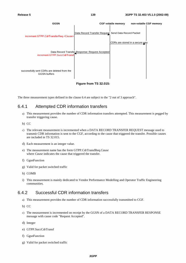
3GPP
3GPP TS 32.403 V5.1.0 (2002-09)139Release 5
Data Record Transfer Request: Send Data Record Packetincrement GTPP.CdrTransferReq.<Cause>
CDRs are stored in a secure way
Data Record Transfer Response: Request Acceptedincrement GTPP.SuccCdrTransf
successfully sent CDRs are deleted from the GGSN buffers
CGF volatile memory non-volatile CGF memoryGGSN
Figure from TS 32.015:
The three measurement types defined in the clause 6.4 are subject to the "2 out of 3 approach".
6.4.1 Attempted CDR information transfers
a) This measurement provides the number of CDR information transfers attempted. This measurement is pegged by transfer triggering cause.
b) CC
c) The relevant measurement is incremented when a DATA RECORD TRANSFER REQUEST message used to transmit CDR information is sent to the CGF, according to the cause that triggered the transfer. Possible causes are included in TS 32.015.
d) Each measurement is an integer value.
e) The measurement name has the form GTPP.CdrTransfReq.Cause where Cause indicates the cause that triggered the transfer.
f) GgsnFunction
g) Valid for packet switched traffic
h) COMB
i) This measurement is mainly dedicated to Vendor Performance Modelling and Operator Traffic Engineering communities.
6.4.2 Successful CDR information transfers
a) This measurement provides the number of CDR information successfully transmitted to CGF.
b) CC
c) The measurement is incremented on receipt by the GGSN of a DATA RECORD TRANSFER RESPONSE message with cause code "Request Accepted".
d) Integer
e) GTPP.SuccCdrTransf
f) GgsnFunction
g) Valid for packet switched traffic

3GPP
3GPP TS 32.403 V5.1.0 (2002-09)140Release 5
h) COMB
i) This measurement is mainly dedicated to Vendor Performance Modelling and Operator Traffic Engineering communities.
6.4.3 Failed CDR information transfers
a) This measurement provides the number of CDR information failed to be transferred to CGF. This measurement is pegged by failure cause. Possible causes are included in TS 32.015.
b) CC
c) The relevant measurement is incremented on receipt by the GGSN of a DATA RECORD TRANSFER RESPONSE message according to the failure cause.
d) Each measurement is an integer value.
e) The measurement name has the form GTPP.FailCdrTransf.Cause where Cause indicates the failure cause.
f) GgsnFunction
g) Valid for packet switched traffic
h) COMB
i) This measurement is mainly dedicated to Vendor Performance Modelling, Operator Maintenance and Operator Traffic Engineering communities.
6.5 IP measurements The performance counters presented in this subclause are mainly intended to:
- monitor the bearer traffic exchanged between the GGSN and the external PDN on the Gi interface
- establish the session profile (including IP average packet size, uplink and downlink IP traffic per session, …), possibly per traffic class
- and monitor the GGSN load (through measurements such as the total bit rate handled by the node, the ratio of packets discarded at GGSN level, …).
These counters are associated to IP protocol on the Gi interface.
These counters are proposed to be screened with regards to the protocol configuration options, as defined in TS 24.008 and TS 29.061, i.e. a set of the counters is associated to any valid combination of the different options below:
- transparent or non-transparent access to the external PDN
- user data encryption (IPSec, …)
- tunneling of packets onto the Gi interface
Any valid combinaton of these options fully defines a "Gi reference point". The figure below gives an overview of some Gi reference points.

3GPP
3GPP TS 32.403 V5.1.0 (2002-09)141Release 5
Figure: Overview of some Gi reference points
6.5.1 Number of incoming IP data packets on the Gi interface
This measurement provides the number of IP data packets received on the Gi interface. This measurement is pegged by traffic class of the related PDP context.
a) CC
b) The relevant measurement is incremented on receipt of an IP data packet on the Gi interface, according to the traffic class of the related PDP context. In case of a PDP context activated with R97/98 QoS attributes, the field traffic class used for screening is derived from delay class, as ruled in TS 23.107. See also 07 and TS 29.061.
c) A single integer value per measurement type defined in e)
d) IP.IncDataPkt.Bgrd IP.IncDataPkt.Conv IP.IncDataPkt.Intact IP.IncDataPkt.Strm
e) GgsnFunction, per Gi reference point
f) Valid for packet switched traffic
g) COMB
h) This measurement is mainly dedicated to Vendor Performance Modelling, Operator Traffic Engineering and Vendor Development Engineering communities.

3GPP
3GPP TS 32.403 V5.1.0 (2002-09)142Release 5
6.5.2 Number of outgoing IP data packets on the Gi interface
a) This measurement provides the number of IP data packets sent onto the Gi interface. This measurement is pegged by traffic class of the related PDP context.
b) CC
c) The relevant measurement is incremented on transmission of an IP data packet on the Gi interface, according to the traffic class of the related PDP context. In case of a PDP context activated with R97/98 QoS attributes, the field traffic class used for screening is derived from delay class, as ruled in TS 23.107. See also TS 29.061.
d) A single integer value per measurement type defined in e)
e) IP.OutDataPkt.Bgrd IP.OutDataPkt.Conv IP.OutDataPkt.Intact IP.OutDataPkt.Strm
f) GgsnFunction, per Gi reference point
g) Valid for packet switched traffic
h) COMB
i) This measurement is mainly dedicated to Vendor Performance Modelling, Operator Traffic Engineering and Vendor Development Engineering communities.
6.5.3 Number of IP data packets discarded due to node congestion
a) This measurement provides the number of IP data packets discarded. This measurement is pegged by traffic class of the related PDP context.
b) CC
c) The relevant measurement is incremented when a received IP data packet is discarded due to node congestion, according to the traffic class of the related PDP context. In case of a PDP context activated with R97/98 QoS attributes, the field traffic class used for screening is derived from delay class, as ruled in TS 23.107. See also TS 29.061.
d) A single integer value per measurement type defined in e)
e) IP.DiscDataPkt.Bgrd IP.DiscDataPkt.Conv IP.DiscDataPkt.Intact IP.DiscDataPkt.Strm
f) GgsnFunction, per Gi reference point
g) Valid for packet switched traffic
h) COMB
i) This measurement is mainly dedicated to Vendor Performance Modelling, Operator Traffic Engineering and Vendor Development Engineering communities.
6.5.4 Number of octets of incoming IP data packets on the Gi interface
a) This measurement provides the number of IP payload octets received on the Gi interface. This measurement is pegged by traffic class of the related PDP context.
b) CC
c) The relevant measurement is incremented on receipt of an IP data packet on the Gi interface, according to the traffic class of the related PDP context. In case of a PDP context activated with R97/98 QoS attributes, the field

3GPP
3GPP TS 32.403 V5.1.0 (2002-09)143Release 5
traffic class used for screening is derived from delay class, as ruled in TS 23.107. The data packet size is extracted from the IP header and added on to the measurement value. See nd TS 29.061.
d) A single integer value per measurement type defined in e)
e) IP.IncDataOct.Bgrd IP.IncDataOct.Conv IP.IncDataOct.Intact IP.IncDataOct.Strm
f) GgsnFunction, per Gi reference point
g) Valid for packet switched traffic
h) COMB
i) This measurement is mainly dedicated to Vendor Performance Modelling and Operator Traffic Engineering communities.
6.5.5 Number of octets of outgoing IP data packets on the Gi interface
a) This measurement provides the number of IP payload octets sent onto the Gi interface. This measurement is pegged by traffic class of the related PDP context.
b) CC
c) The relevant measurement is incremented on transmission of an IP data packet on the Gi interface, according to the traffic class of the related PDP context. In case of a PDP context activated with R97/98 QoS attributes, the field traffic class used for screening is derived from delay class, as ruled in TS 23.107. The data packet size is extracted from the IP header and added on to the measurement value. See TS 29.061.
d) A single integer value per measurement type defined in e)
e) IP.OutDataOct.Bgrd IP.OutDataOct.Conv IP.OutDataOct.Intact IP.OutDataOct.Strm
f) GgsnFunction, per Gi reference point
g) Valid for packet switched traffic
h) COMB
i) This measurement is mainly dedicated to Vendor Performance Modelling and Operator Traffic Engineering communities.

3GPP
3GPP TS 32.403 V5.1.0 (2002-09)144Release 5
Annex A (informative): Examples for "(n-1) out of n" approach The measurements result values generated by a NE are often redundant, or the info contained in the measurement results can be obtained in a number of different ways.
The "(n-1) out of n" approach allows a vendor to implement a subset of 3GPP defined measurements, for example if there exists a relation (A+B=C) then any 2 out of 3 defined measurements A, B, C are sufficient information to calculate the third (n=3). In case there exists a relation (A+B+C=D), then any 3 out of the 4 would suffice, and the same kind of approach would be applicable.
A.1 Attempt/success/failure procedure measurements Consider the number of attempts to start a specific procedure (e.g. RRC connection establishment). Some of these attempts will fail, some will be successful. Three different counters can be defined to measure these procedures: an attempt counter, a success counter, and a failure counter, but in fact only 2 may be provided, since we have the fixed relation (#success + #failure) = #attempt.
It is to be noted that all combinations do not provide the same level of details. For example, in the case only #attempt and #success are provided, it will not be possible to retrieve the detailed failure causes.
The three measurement types defined in subclause 4.4 are subject to the "(n-1) out of n" approach with n=3:
- Attempted RRC connection establishments.
- Failed RRC connection establishments.
- Successful RRC connection establishments.
The "(n-1) out of n" approach is also applicable for more complex measurements split according to a specific criterion, e.g. Queuing. For example, the CS measurements described in subclause 4.1 are subject to a 4 out of 5 approach:
- Attempted RAB establishments for CS domain.
- Successful RAB establishments without queuing for CS domain.
- Failed RAB establishments without queuing for CS domain.
- Successful RAB establishments with queuing for CS domain.
- Failed RAB establishments with queuing for CS domain.
Any of the five measurements can be calculated from the four others but all combinations will not provide the same level of details (e.g. failure causes).
A.2 GSM/UMTS combined measurements With relation to the field H of the measurement template, a measurement indicated with GSM/UMTS is an example of the "(n-1) out of n" approach with n=3 since (GSM + UMTS) = Combined.
In that case, all concerned measurements are included in the same template but the vendor may provide only 2 sub-measurements out of 3.

3GPP
3GPP TS 32.403 V5.1.0 (2002-09)145Release 5
The measurement described in subclause 5.6.1 is subject to the "(n-1) out of n" approach with n=3:
- SM.AttActPdpContext (attempted context activation procedures with no distinction between GSM and UMTS).
- SM.AttActPdpContext.G (attempted context activation procedures for GSM only).
- SM.AttActPdpContext.U (attempted context activation procedures for UMTS only).
A.3 Embedded "(n-1) out of n" approaches It is also possible to combine the approaches described above. For example, the measurements described in subclause 5.5 are subject to the "(n-1) out of n" approach at two levels.
Firstly, measurements are split according to the CS/PS domain, for example:
- attempted CS SMS mobile originating;
- attempted PS SMS mobile originating;
- attempted SMS mobile originating;
where any of the three measurements can be calculated from the two others.
Secondly, each measurement provides 3 sub-measurements, for example for Attempted CS SMS mobile originating:
- SMS.AttMoCS;
- SMS.AttMoCS.G;
- SMS.AttMoCS.U;
where any of the three sub-measurements can be calculated from the two others.
3GPP
3GPP TS 32.403 V5.1.0 (2002-09)146Release 5
Annex B (Informative): Top-Down Performance Measurement Definition Process
B.1 Scope of this annex Performance measurements within wireless telecommunications networks are required in order to meet the needs of the diverse community of end-users of those measurements. New features develop, networks evolve and operating conditions change without sufficient consideration given to the measurements needed to keep the network running efficiently. While Equipment Vendors define measurements to satisfy their particular needs, other perspectives, especially the voice of the Network Operator, are sometimes lost during Equipment Vendor development processes. Similarly, Network Operators sometimes request measurements without fully understanding who will be using the data or what actions those people will take based on the collected data. A coherent, simple, top-down methodology for defining performance measurements is lacking in the telecommunications industry.
This annex proposes a methodology to handle the above problems. In particular, multiple user communities have been defined representing the end-users of system measurements. Performance goals and measurements are defined considering these same user communities. The definition includes identification of specific problem scenarios and corrective actions to be taken by the appropriate user community.
Measurements defined using this methodology can be contributed to 3GPP SA5 for potential adoption and inclusion in the present document. It is believed that this methodology will help reduce development costs for the Equipment Vendors and reduce operational costs for the Network Operators.
B.2 Overview Performance measurements are important to the proper and efficient functioning of wireless telecommunications networks. They have numerous uses related to resource utilization, expansion planning, network optimisation, operating problem diagnosis and network availability monitoring. For the wireless telecommunications world, product performance measurements are necessary to support multiple communities of users.
In addition, once performance measurements are defined for a wireless telecommunication network they must be maintained. The evolution of a wireless telecommunication network for capacity increases and feature extensions leads to the evolution of the collected measurements. Performance measurements need to be added, modified and made obsolete from the overall measurement repository. These changes must be defined completely and accurately to meet the requirements of each community of users.
The development of a performance measurement life cycle process to oversee this need is proposed in this annex. The life cycle process addresses the multiple user communities whose perspectives are needed to supply the requirements for the performance measurements.
The proposed performance measurement life cycle process is a usage-based process. The basic Goal, Question, Metric (GQM) method is enhanced to define problem scenarios and corrective actions. These descriptions are not only used to filter out proposals for performance measurements that provide no defined benefit, but also support user community training in the use of the performance measurements.
The remainder of this annex is organised as follows.
• Clause B.3 defines Measurement User Communities for wireless telecommunications;
• Clause B.4 discusses the GQM and the Enhanced GQM methods;
• Clause B.5 discusses the measurement life cycle process;
• Clause B.6 provides conclusions.

3GPP
3GPP TS 32.403 V5.1.0 (2002-09)147Release 5
B.3 Measurement User Communities One objective of Performance Management as a functional subset of operations and maintenance processes is to define sets of measurements. Typical definition criteria revolve around measuring activity within the network in terms of volume, speed and accuracy. While this approach produces measurement data it does not completely address the needs and uses of the multiple consumers of network performance measurement information. The Enhanced GQM methodology extends the measurement definition criteria to better satisfy multiple groups with diverse needs for these measurements.
A qualitative judgement as to the efficacy of a Performance Management subsystem is how well served these different groups are by the measurements provided. To better understand these needs, five generic categories of users, outlined definitions and examples of their needs and requirements for measurements taken from their wireless telecommunications network are defined. These groups are referred to as measurement user communities. These six communities are:
1. Network Operator's Business Community
2. Network Operator's Maintenance Community
3. Network Operator's Traffic Engineering Community
4. Network Operator's Customer Care Community
5. Equipment Vendor's Performance Modelling Community
6. Equipment Vendor's Development Engineering Community
B.3.1 Network Operator Business Community The first measurement user community is the Network Operator's Business Community. This community is defined under the assumption that the wireless telecommunications network is fully operational, adequately engineered for traffic load per quality of service definitions and in commercial service. The primary objective of this community is to guarantee the financial health and welfare of the Operating Company. They expect a properly configured wireless telecommunications network to supply the revenue per subscriber unit necessary to meet their financial goals.
An understanding of the elasticity of demand can help the Business Community maximize profits within their product pricing strategy as they alter prices according to various mixes of services. Typical measurements of interest to this community are those based on the actual volumes of calls completed by service type. This call volume information can lead to trends of usage over time. Correlation between price mix and call volumes can help to identify pricing strategies geared towards increasing revenue per subscriber unit.
B.3.2 Network Operator Maintenance Community The second measurement user community is the Network Operator's Maintenance Community. This community is defined under the assumption that the wireless telecommunications network is less than fully operational, adequately engineered for traffic load per quality of service definitions and in commercial service. The primary objective of this community is to reduce Mean Time to Repair faults that occur within the network equipment of the Operating Company.
The baseline metric for this community is the availability of the network equipment, where availability is composed of the sum of scheduled and unscheduled outages to the network equipment. Unscheduled outages are influenced by the inherent hardware and software quality of the products provided to the operating company. While the Maintenance Community has no direct control over that quality, they do have control over the second component of scheduled outage, Mean Time to Repair.
Mean Time to Repair is influenced by the Mean Time to Detect a fault. This community of user's defines measurements that support detecting or predicting faults within the network equipment.
Measurements that support this community can come from places other than the network equipment, itself. Several Operating Companies have been observed building information systems based on the data provided by Call Detail Records and Billing Records. Correlation is sought within these data between call faults and location within the Network. Detection of these faults serves a dual purpose: it allows the Operating Company a view of performance at the

3GPP
3GPP TS 32.403 V5.1.0 (2002-09)148Release 5
level of their Network Operator (the subscriber) and it allows the Maintenance Community to target specific network equipment for repair.
B.3.3 Network Operator Traffic Engineering Community The third measurement user community is the Network Operator's Traffic Engineering Community. This community is defined under the assumption that the wireless telecommunications network is fully operational, inadequately engineered for current or future traffic load per quality of service definitions and in commercial service. The primary objective of this community is to keep the capacity of the network equipment within 1) the Operating Company's design criteria for the quality of service based on growth of the subscriber base, 2) changes in usage patterns based on pricing strategies and 3) introduction of new services.
The baseline metric for this community is the trend in utilization of the network equipment. A fully instrumented network would allow the Operating Company to understand the trend in performance of their principle capital investment and any leased services. As these trends pass thresholds of performance, purchasing decisions or volume pricing discounts could be triggered.
B.3.4 Network Operator Customer Care Community The fourth measurement user community is the Network Operator's Customer Care Community. This community is defined under the assumption that the wireless telecommunications network is fully operational, functioning at a less than optimal level resulting in end-user dissatisfaction and in commercial service. The primary objective of this community is interfacing with the end-user customers of offered services for the purpose of establishing and maintaining end-user customer satisfaction. This may include customer care responsibilities such as Customer Relationship Management (CRM), Service Level Agreement (SLA) management, quality of service (or QoS) management etc.
This community is interested in defining measurements related to the end-user customer experience with the network Operator's offered services in the areas of CRM, SLA, QoS, problem reports, etc. Decisions on how to best handle customer dissatisfaction or how to keep customers from becoming dissatisfied are based on these types of measurements.
B.3.5 Equipment Vendor Performance Modelling Community The fifth measurement user community is Equipment Vendor's Performance Modelling Community. This community is defined under the assumption that the wireless telecommunications network is fully operational, adequately engineered for traffic load per quality of service definitions and in some level of call capable service. The primary objective of this community is to guarantee that the models used during analysis and design phases conform to real-world observations of the network equipment of the Operating Company.
While this community is not within the Operating Company it still provides beneficial service to the Operating Company by managing the development of subsequent features that are in line with the actual performance characteristics of the network. Many decisions within the development life cycle depend on models developed prior to shipping the product. These models need to be calibrated to network performance once the product is released. Definition of measurements in concert with calibrating these models requires the direct involvement of the people developing the models.
The network that transports Network Management data often is the same network that carries call control traffic. Clearly, the knowledge of volume levels of this traffic during anomalous operating conditions is important in order to understand the total impact to call processing. This community would define measurements to allow the monitoring of this type of phenomena.
B.3.6 Equipment Vendor Development Engineering Community The sixth measurement user community is Equipment Vendor's Development Engineering Community. This community is also defined under the assumption that the wireless telecommunications network is fully operational, adequately engineered for traffic load per Quality of Service or Service Level Agreement definitions and in commercial service. The primary objective of this community is to guarantee that the implementations of the designs conform to real-world observations of the network equipment of the Operating Company.

3GPP
3GPP TS 32.403 V5.1.0 (2002-09)149Release 5
While this community also is not within the Operating Company, it still provides beneficial service to the Operating Company. The implementation of new algorithms carries some finite risk of performance in the Network Operator environment versus the lab environment. Many times simulators of network activity are developed to support the verification of these algorithms. These simulations need to be calibrated to network performance once the product is released. Definition of measurements in concert with calibrating these simulations requires the direct involvement of the people developing the simulations.
B.3.7 User Community Conclusion The six measurement communities are broken into four Network Operator based groups and two Equipment Vendor groups. However, experience shows that the measurements defined for these groups are not mutually exclusive. Other groups may also use measurements needed by a particular group for the same or different purposes. Thus, the accurate definition of the measurements and how to use them is necessary to allow the Network Operator to properly combine these measurements into more complex analyses.
B.4 Enhanced GQM The Goal, Question, Metric (GQM) method requires measurement user communities to help define goals and metrics. This clause first presents the standard GQM method and then presents an enhanced GQM method, which provides the measurement user communities a broader understanding of how metrics are used. The term 'Metric' in GQM means the same as 'measurement'.
B.4.1 GQM Methodology Basili and Weiss [23] and others originally proposed the GQM method. This methodology provides a systematic approach for defining metrics that can be collected and analysed to determine whether or not a goal has been reached. This methodology was originally created for quality assurance of software development processes, but has been applied to other areas. GQM is comprised of the following three steps.
1. Identify and define Goals for a particular group;
2. Refine goals into quantifiable Questions;
3. Define Metrics that will answer the questions.
Goals are defined in terms of a purpose and a perspective. The purpose specifies the object to be analysed and why it will be analysed. The perspective specifies the relevant aspects of the object and which measurement user community is interested in the aspects.
Execution of the GQM methodology results in the formation of a GQM model. A GQM model contains the set of defined Goals, Questions and Metrics. A GQM model provides trace-ability from the goals to the associated metrics. Figure B1 shows an example of a GQM model.

3GPP
3GPP TS 32.403 V5.1.0 (2002-09)150Release 5
Figure B1: GQM Model
GQM definition templates are often used to help produce consistent goal, question and/or metric definitions. An example of a Goal template is shown below [22]:
Purpose: To (characterize evaluate, predict, motivate, etc.) the (process product model, metric, etc.) in order to (understand, assess, manage, engineer, learn, improve, etc.) it. Example: To evaluate the system testing methodology in order to improve it.
Perspective: Examine the (cost, effectiveness, correctness, defects, changes, product metrics, reliability, etc.) from the point of view of the (developer, manager, Network Operator, corporate perspective, etc.). Example: Examine the effectiveness from the developer's point of view.
B.4.2 Enhanced GQM (EGQM) Methodology As it stands, the GQM methodology works well for defining metrics, but falls short in several areas. The original GQM methodology was enhanced to better fit within the wireless telecommunications industry for the following reasons:
a) Allow wireless measurement user communities to specify their needs at the beginning of the performance measurement life cycle rather than waiting for product to be delivered.
b) Allow wireless measurement user communities to understand what performance measurements are being designed for them in time to modify the associated collection, analysis and reporting processes.
c) Allow wireless measurement user communities to understand how they should analyse collected measurement data and what actions they should take when analysis has been completed.
d) Provide criteria for rejecting unnecessary goals, useless measurements, or measurements that can not be properly collected, analysed or understood.
e) Provide criteria for architecting metrics into the appropriate wireless network device (based on network traffic capacity, device CPU and memory capacity, data collection capabilities, etc.).
f) Allow for consistent measurement definition by providing Enhanced GQM model definition and measurement definition templates.
g) Help reduce development costs for Equipment Providers and reduce operational costs for the Network Operator.
The Enhanced GQM, or EGQM, methodology is comprised of the following four steps.
1. Identify and define measurement goals for a particular measurement user community;
2. Refine measurement goals into quantifiable problem scenarios;
Metric a
Question 1 Metric b
Goal A Question 2 Metric c
Question 3 Metric d
Goal B Question 4 Metric e
Question 5 Metric f
Metric g

3GPP
3GPP TS 32.403 V5.1.0 (2002-09)151Release 5
3. Define measurements that will determine if the goal is being accomplished;
4. Define corrective actions.
EGQM's first and third steps are similar to GQM's first and third steps. EGQM's second step is different than GQM's second step in that it focuses on problem scenarios associated with the goal rather than on questions associated with the goal. Problem scenarios are descriptions of real world problems the measurement user community has or will experience. Each problem scenario represents a particular aspect of the associated goal. Problem scenarios include definitions of any formulas that will allow the measurement user community to analyse the problem scenario after metric data has been collected from the field. EGQM's fourth step is new. Corrective actions are descriptions of what the measurement user community should do based on analysis of metric data collected from the resulting wireless network.
Execution of the EGQM methodology results in the formation of an EGQM model. An EGQM model contains the set of defined goal, problem scenarios, metrics and corrective actions. An EGQM model also provides trace-ability from the goals to the associated corrective actions. Figure B2 shows an example of an EGQM model.
Figure B2: EGQM Model
EGQM has definition templates for producing an EGQM model and for defining metrics. The EGQM model definition template is shown in Table B1. The EGQM metric definition template that is useful for 3GPP SA5 activities is defined in subclause 3.3 of the present document.
Table B1: EGQM Model Definition Template
As described in clause B.3, six measurement user communities have been defined for the wireless telecommunications industries. EGQM supports all six communities. Representatives from each community participate in all four steps of the EGQM methodology. This allows user communities to specify exactly what they need and/or want and to know exactly how they will use the metrics before any software is developed. Participation in the EGQM process increases Network Operator satisfaction through early definition of operational practices (including corrective actions) and increases product knowledge within the Network Operator organization.
Metric a
Problem Scenario 1 Metric b Corrective Action 1
Goal A Metric c
Problem Scenario 2 Metric d Corrective Action 2
Metric e Corrective Action 3
Goal: Provides the name of goal and non-ambiguous definition of what needs to be accomplished. Also provides the measurement user communities the goal is associated with.
Problem Scenario(s): Provides a description of the problem scenario associated with the goal. Contains a description of how performance measurements will be used by the user in order to meet the goal.
Required Metric(s): Provides a list of metrics required to assess the problem scenario to see if the goal is being accomplished.
Corrective Action(s): Provides descriptions of actions the user can execute based on data collected from the wireless network. Contains descriptions of expected metric data values and how those values work with the Problem Scenarios definitions.

3GPP
3GPP TS 32.403 V5.1.0 (2002-09)152Release 5
The EGQM model definition and metric definition templates provide the mechanism to reject unnecessary goals, useless metrics, or metrics that can't be properly collected or computed. Reasons for the rejection of a goal include the following:
a) Non-ambiguous goal definition could not be determined;
b) Problem scenarios could not be determined;
c) Definition of how performance measurement will be used within a problem scenario could not be determined;
d) Corrective actions could not be determined;
e) Metrics could not be defined to support problem scenario definitions;
f) Required metrics could not be architected into network devices for any of the following reasons:
1) Network device could not collect metric due to CPU utilization issues;
2) Network device could not collect and/or store metric due to memory issues;
3) Network could not support the uploading of measurement data from network devices to network manager;
4) Network manager could not collect and/or store measurement data due to memory issues.
B.5 Measurements Life Cycle Process If the uses of performance measurements were confined to feature releases and occasional changes to those features, then EGQM would suffice. However, user community needs evolve, operating conditions change, performance models are validated, new services are introduced, etc. As these conditions change, performance measurements may need to change. Such considerations point to the need for a complete measurements life cycle model.
A simple life cycle model to handle performance measurement changes is depicted in Figure B3. New performance measurement goal and metric definitions are provided through new features. These are made available with major releases.
Figure B3: Measurement Life Cycle
Performance measurements may need to be periodically reviewed. Goal and metric definition updates made during this process are generally instantiated at major releases. When metrics are no longer useful they can be made obsolete and eventually deleted. A waiting period between obsolescence and deletion allows user communities time to implement and test out new metrics and analyses that are meant to replace existing metrics and analyses.
B.6 Conclusion In the past, definition of performance measurements of wireless telecommunications networks was focused mainly on satisfying the needs of the Equipment Vendor Performance Modelling and Development Engineering measurement user
New Functional Obsolete
Modify Deleted

3GPP
3GPP TS 32.403 V5.1.0 (2002-09)153Release 5
communities. The needs of the wireless telecommunications Network Operator were not always addressed. The Performance Measurement Definition process described in this annex addresses the needs of all measurements user communities. The process also provides additional benefits, including the following:
- Allow measurement communities to specify their needs up front;
- Allow measurement communities to prepare for and modify their measurement monitoring and reporting processes before product is released to them;
- Allow measurement communities to know what actions they need to perform when assessing collected measurements;
- Provides method for rejecting unrealistic goals and measurements;
- Provides method for best architecting measurements into network devices;
- Provides method for producing consistent measurement definitions;
- Provides method for managing measurements life cycle including measurement creation, modification and obsoletion.
The EGQM methodology may be used for:
- analyse and assess performance areas that are not well understood or are highly complex;
- non-straightforward cases where it is difficult to create useful measurement proposals;
- an understanding of real value is required before useful measurement proposals can be created;
- mine for missing measurements;
- mine for conflicting, overlapping, or existing measurements that are no longer useful.
In summary, the EGQM methodology may be used by any company to generate measurement definitions that can then be contributed to 3GPP SA5 for potential inclusion in the present document.
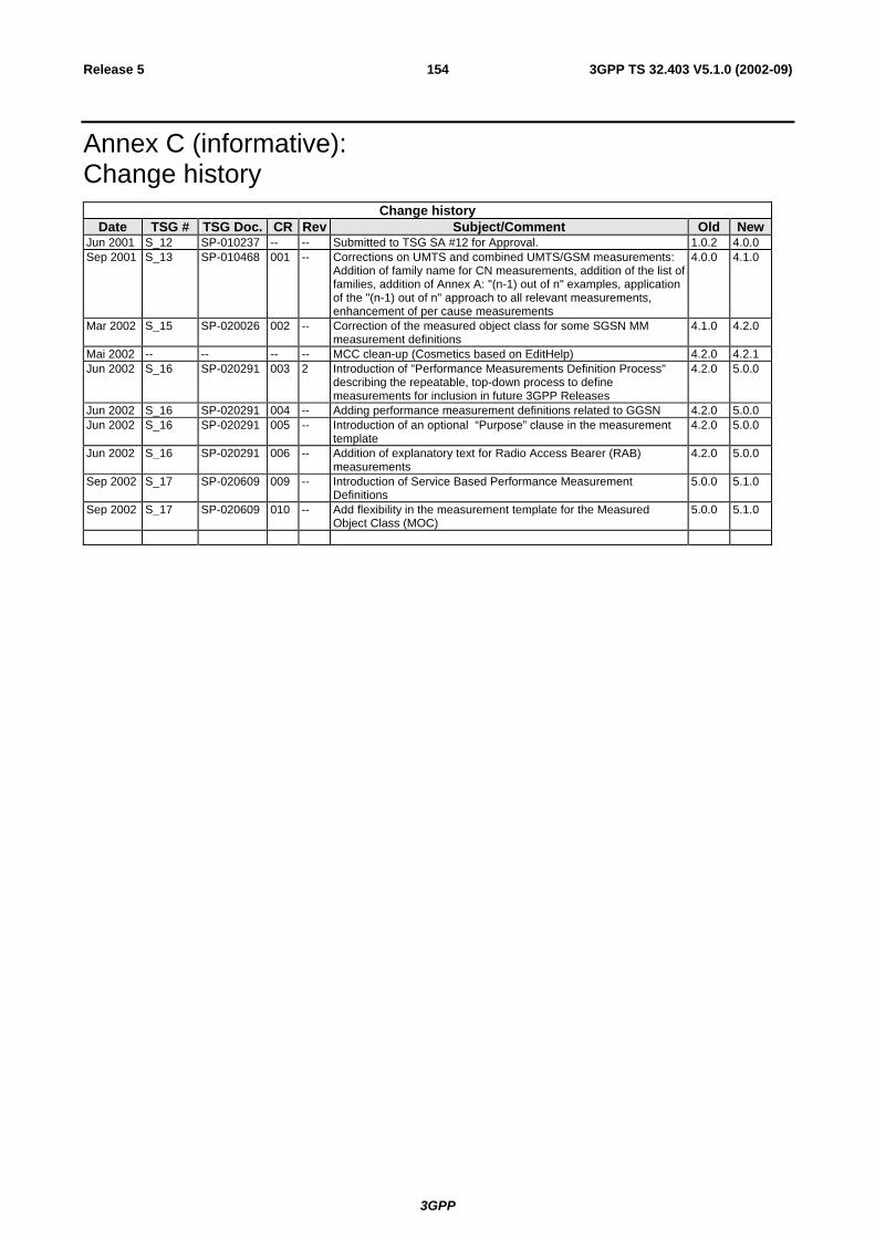
3GPP
3GPP TS 32.403 V5.1.0 (2002-09)154Release 5
Annex C (informative): Change history
Change history Date TSG # TSG Doc. CR Rev Subject/Comment Old New
Jun 2001 S_12 SP-010237 -- -- Submitted to TSG SA #12 for Approval. 1.0.2 4.0.0Sep 2001 S_13 SP-010468 001 -- Corrections on UMTS and combined UMTS/GSM measurements:
Addition of family name for CN measurements, addition of the list of families, addition of Annex A: "(n-1) out of n" examples, application of the "(n-1) out of n" approach to all relevant measurements, enhancement of per cause measurements
4.0.0 4.1.0
Mar 2002 S_15 SP-020026 002 -- Correction of the measured object class for some SGSN MM measurement definitions
4.1.0 4.2.0
Mai 2002 -- -- -- -- MCC clean-up (Cosmetics based on EditHelp) 4.2.0 4.2.1Jun 2002 S_16 SP-020291 003 2 Introduction of "Performance Measurements Definition Process"
describing the repeatable, top-down process to define measurements for inclusion in future 3GPP Releases
4.2.0 5.0.0
Jun 2002 S_16 SP-020291 004 -- Adding performance measurement definitions related to GGSN 4.2.0 5.0.0Jun 2002 S_16 SP-020291 005 -- Introduction of an optional “Purpose” clause in the measurement
template 4.2.0 5.0.0
Jun 2002 S_16 SP-020291 006 -- Addition of explanatory text for Radio Access Bearer (RAB) measurements
4.2.0 5.0.0
Sep 2002 S_17 SP-020609 009 -- Introduction of Service Based Performance Measurement Definitions
5.0.0 5.1.0
Sep 2002 S_17 SP-020609 010 -- Add flexibility in the measurement template for the Measured Object Class (MOC)
5.0.0 5.1.0