ts-3ga-29.007(rel4)v4.3 call flows ... 11.2 handover from gsm to umts
TRANSCRIPT

TS-3GA-29.007(Rel4)v4.3.0
General requirements on interworking between the Public Land Mobile
Network (PLMN) and the Integrated Services Digital Network (ISDN) or
Public Switched Telephone Network (PSTN)
Feb 26, 2002
THE TELECOMMUNICATION TECHNOLOGY COMMITTEE

i
TS-3GA-29.007(Rel4)v4.3.0 General requirements on interworking be tween the Public Land Mobile Network (PLMN) and the Integrated Services Digi tal Network (ISDN) or Public Switched Telephone Network (PSTN)
<Remarks>
1. Application level of English description
Application level : E2
English description is included in the text and figures of main body, annexes and appendices.
2. Relationship with international recommendations and standards
This standard is standardized based on the Technical Specification 29.007(Version 4.3.0) approved by 3GPP.
3. Departures from international recommendations
Changes to original standard
Standards referred to in theoriginal standard, which are replaced by TTC standards.
Standards referred to in the original standard should be replaced by derived TTC standards.
4. IPR
There is no specific description about IPR in this standard.
5. Technical Committee
Technical Committee 6
3GPP TS 29.007 V4.3.0 (2001-12)Technical Specification
3rd Generation Partnership Project;Technical Specification Group Core Network;
General requirements on interworkingbetween the Public Land Mobile Network (PLMN) and the
Integrated Services Digital Network (ISDN) orPublic Switched Telephone Network (PSTN)
(Release 4)
The present document has been developed within the 3rd Generation Partnership Project (3GPP TM) and may be further elaborated for the purposes of 3GPP. The present document has not been subject to any approval process by the 3GPP Organisational Partners and shall not be implemented. This Specification is provided for future development work within 3GPP only. The Organisational Partners accept no liability for any use of this Specification. Specifications and reports for implementation of the 3GPP TM system should be obtained via the 3GPP Organisational Partners' Publications Offices.
3GPP
3GPP TS 29.007 V4.3.0 (2001-12)2Release 4
Keywords UMTS, GSM, interworking, ISDN, PSTN, PLMN
3GPP
Postal address
3GPP support office address 650 Route des Lucioles - Sophia Antipolis
Valbonne - FRANCE Tel.: +33 4 92 94 42 00 Fax: +33 4 93 65 47 16
Internet http://www.3gpp.org
Copyright Notification
No part may be reproduced except as authorized by written permission. The copyright and the foregoing restriction extend to reproduction in all media.
© 2002, 3GPP Organizational Partners (ARIB, CWTS, ETSI, T1, TTA,TTC).
All rights reserved.

3GPP
3GPP TS 29.007 V4.3.0 (2001-12)3Release 4
Contents
Foreword.............................................................................................................................................................6
1 Scope ........................................................................................................................................................7
2 References ................................................................................................................................................7 3 Definitions and abbreviations.................................................................................................................11 3.1 Abbreviations ........................................................................................................................................................ 12
4 Introduction ............................................................................................................................................12
5 Void........................................................................................................................................................13
6 Network Characteristics .........................................................................................................................13 6.1 Key Characteristics of Networks Concerned......................................................................................................... 13 6.1.1 Characteristics of PLMNs................................................................................................................................ 13 6.1.2 Characteristics of PSTNs ................................................................................................................................. 14 6.1.3 Characteristics of ISDN ................................................................................................................................... 14 7 Interworking classifications ...................................................................................................................14 7.1 Service interworking ............................................................................................................................................. 14 7.2 Network interworking ........................................................................................................................................... 14 7.3 Signalling interworking ......................................................................................................................................... 15 7.4 Numbering............................................................................................................................................................. 15 7.5 Supplementary service interworking ..................................................................................................................... 15 8 Compatibility and subscription checking...............................................................................................15
9 Interworking to PSTN............................................................................................................................16 9.1 Speech Calls .......................................................................................................................................................... 16 9.1.1 Interworking indications to PLMN terminal.................................................................................................... 16 9.1.2 Transmission aspects ....................................................................................................................................... 16 9.1.3 Generation of In-band Tones and Announcements (PLMN-PSTN) ................................................................ 16 9.2 Data Calls .............................................................................................................................................................. 16 9.2.1 Network interworking mobile originated......................................................................................................... 17 9.2.1.1 Selection of interworking function .................................................................................................................. 17 9.2.1.2 Modem Selection ............................................................................................................................................. 17 9.2.1.3 Mapping of BC-IE from PLMN to ISUP (or other)......................................................................................... 18 9.2.2 Network Interworking Mobile terminated PSTN Originated .......................................................................... 18 9.2.2.1 Multi-numbering Scheme ................................................................................................................................ 18 9.2.2.2 Single-numbering Scheme............................................................................................................................... 20 9.2.3 Transparent service support ............................................................................................................................. 21 9.2.3.1 Structure of the MSC/IWF for UMTS ............................................................................................................. 21 9.2.3.2 Structure of the MSC/IWF for GSM................................................................................................................ 22 9.2.3.3 Mapping of signalling MS/MSC/IWF to modem interface requirements........................................................ 22 9.2.3.4 Establishment of end-to-end terminal synchronizations .................................................................................. 23 9.2.3.4.1 Terminating side (towards the MS / UE) ................................................................................................... 24 9.2.3.4.1.1 GSM Traffic channel types TCH/F4.8 and TCH/F9.6 ............................................................................... 24 9.2.3.4.1.2 GSM Traffic channel type TCH/F14.4....................................................................................................... 24 9.2.3.4.2 Transit side (towards the fixed network).................................................................................................... 24 9.2.3.5 Network Independent Clocking (NIC)............................................................................................................. 25 9.2.4 Non-transparent service support ...................................................................................................................... 25 9.2.4.1 Structure of the MSC/IWF for UMTS ............................................................................................................. 26 9.2.4.2 Structure of the MSC/IWF for GSM................................................................................................................ 26 9.2.4.3 Re-constitution of user data ............................................................................................................................. 26 9.2.4.4 Layer 2 relay functionality............................................................................................................................... 26 9.2.4.5 In band signalling mapping flow control ......................................................................................................... 26 9.2.4.5.1 Conditions requiring flow control towards the fixed network.................................................................... 27 9.2.4.5.2 Conditions requiring flow control towards the MS .................................................................................... 27 9.2.4.6 Data buffers ..................................................................................................................................................... 27

3GPP
3GPP TS 29.007 V4.3.0 (2001-12)4Release 4
9.2.4.6.1 Transmit buffers (towards MS) .................................................................................................................. 27 9.2.4.6.2 Receive buffers (from MS) ........................................................................................................................ 27 9.2.4.7 Transportation of the Break condition ............................................................................................................. 28 9.2.4.8 In band signalling mapping modem status information ................................................................................... 28 9.2.4.9 Support of out-band flow control..................................................................................................................... 29 9.2.4.10 Establishment of end-to-end terminal synchronizations............................................................................. 29 9.2.4.10.1 Terminating side (towards the MS / UE) ................................................................................................... 29 9.2.4.10.2 Transit side (towards the fixed network).................................................................................................... 29 9.2.4.11 Data compression ....................................................................................................................................... 30 9.2.4.12 Service level up and down grading ............................................................................................................ 30 9.2.5 DTE/DCE interface (Filtering) ........................................................................................................................ 30 9.3 Interworking Alternate Speech / Facsimile Group 3 Calls .................................................................................... 31 9.3.1 General............................................................................................................................................................. 31 9.3.2 Mobile originated PSTN terminated calls........................................................................................................ 32 9.3.3 PSTN originated mobile terminated calls ........................................................................................................ 32 9.4 3G-H.324/M calls over 3,1kHz audio.................................................................................................................... 32 9.4.1 Mobile originated multimedia call................................................................................................................... 32 9.4.1.1 Call setup ......................................................................................................................................................... 32 9.4.1.2 Fallback to speech after setup .......................................................................................................................... 33 9.4.2 Mobile terminated multimedia call .................................................................................................................. 33 9.4.2.1 Call setup ......................................................................................................................................................... 33 9.4.2.2 Fallback to speech after setup .......................................................................................................................... 34 9.4.3 Seamless data rate change................................................................................................................................ 34
10 Interworking to the ISDN.......................................................................................................................34 10.1 Speech Calls..................................................................................................................................................... 34 10.2 Data Calls ........................................................................................................................................................ 34 10.2.1 Network interworking mobile originated......................................................................................................... 35 10.2.2 Network interworking mobile terminated........................................................................................................ 35 10.2.2.1 General ....................................................................................................................................................... 35 10.2.2.2 Functions in GMSC.................................................................................................................................... 35 10.2.2.3 Functions in HLR....................................................................................................................................... 35 10.2.2.4 Functions in VMSC.................................................................................................................................... 36 10.2.2.5 Call Flows .................................................................................................................................................. 38 10.2.2.6 Mapping Functions..................................................................................................................................... 39 10.2.3 Transparent service support ............................................................................................................................. 52 10.2.3.1 Structure of the MSC/IWF for UMTS........................................................................................................ 52 10.2.3.2 Structure of the MSC/IWF for GSM.......................................................................................................... 53 10.2.3.3 Mapping of signalling MS/MSC/IWF to modem or ISDN (V.110) TA-function interface
requirements ......................................................................................................................................... 53 10.2.3.4 Establishment of end-to-end terminal synchronizations............................................................................. 54 10.2.3.4.1 Terminating side (towards the MS / UE) ................................................................................................... 54 10.2.3.4.1.1 GSM Traffic channel types TCH/F4.8 and TCH/F9.6 ......................................................................... 54 10.2.3.4.1.2 GSM Traffic channel type TCH/F14.4 ................................................................................................. 55 10.2.3.4.1.3 UMTS User Plane................................................................................................................................. 55 10.2.3.4.2 Transit side (towards the fixed network).................................................................................................... 55 10.2.3.5 Network independent Clocking (NIC) ....................................................................................................... 55 10.2.4 Non-transparent service support ...................................................................................................................... 55 10.2.4.1 Structure of the MSC/IWF for UMTS........................................................................................................ 56 10.2.4.2 Structure of the MSC/IWF for GSM.......................................................................................................... 56 10.2.4.3 Re-constitution of user data........................................................................................................................ 57 10.2.4.4 Layer 2 relay functionality ......................................................................................................................... 57 10.2.4.5 In band signalling mapping flow control.................................................................................................... 57 10.2.4.5.1 Conditions requiring flow control - if flow control is provided - towards the fixed network .................... 57 10.2.4.5.2 Conditions requiring flow control towards the MS .................................................................................... 58 10.2.4.6 Data buffers ................................................................................................................................................ 58 10.2.4.6.1 Transmit buffers (towards MS) .................................................................................................................. 58 10.2.4.6.2 Receive buffers (from MS) ........................................................................................................................ 58 10.2.4.7 BREAK Indication ..................................................................................................................................... 58 10.2.4.8 Signalling mapping of modem or ISDN (V.110, V.120 or PIAFS) TA-function status information......... 58 10.2.4.9 Support of out-band flow control ............................................................................................................... 59 10.2.4.10 Synchronizations ........................................................................................................................................ 59

3GPP
3GPP TS 29.007 V4.3.0 (2001-12)5Release 4
10.2.4.10.1 V.110 and V.120 Frame synchronizations............................................................................................ 59 10.2.4.10.2 RLP Frame start indication................................................................................................................... 59 10.2.4.10.3 L2R Frame synchronizations................................................................................................................ 60 10.2.4.10.4 Establishment of end-to-end terminal synchronizations....................................................................... 60 10.2.4.10.4.1 Terminating side (towards the MS) ...................................................................................................... 60 10.2.4.10.4.2 Transit side (towards the fixed network) .............................................................................................. 60 10.2.4.11 Data compression ....................................................................................................................................... 60 10.2.4.12 Additional aspects of V.120 Interworking ................................................................................................. 60 10.2.4.12.1 V.120 Signalling parameters ................................................................................................................ 61 10.2.4.12.2 V.120 Protocol parameters ................................................................................................................... 61 10.2.4.12.3 Data compression on the ISDN ............................................................................................................ 61 10.2.4.12.4 Use of the V.120 Control State (header extension) octet...................................................................... 61 10.2.4.13 Interworking with restricted 64 kbit/s networks......................................................................................... 61 10.2.4.13.1 Rate adaptation ..................................................................................................................................... 61 10.2.4.13.2 MSC - ISDN signalling ........................................................................................................................ 61 10.2.4.14 Service level up and down grading ............................................................................................................ 62 10.2.4.15 Interworking in Frame Tunneling Mode .................................................................................................... 62 10.2.4.16 Additional aspects of PIAFS Interworking ................................................................................................ 62 10.2.5 DTE/DCE interface (Filtering) ........................................................................................................................ 62 10.3 Interworking Alternate speech facsimile group 3 calls.................................................................................... 63 10.3.1 Alternate speech data bearer interworking....................................................................................................... 63 10.3.1.1 General ....................................................................................................................................................... 63 10.3.1.2 Mobile originated ISDN terminated........................................................................................................... 63 10.3.1.3 ISDN originated mobile terminated ........................................................................................................... 63 10.4 3G-H.324/M calls over UDI/RDI .................................................................................................................... 63
11 Interworking between GSM and UMTS ................................................................................................64 11.1 Handover from UMTS to GSM ....................................................................................................................... 64 11.2 Handover from GSM to UMTS ....................................................................................................................... 64 11.2.1 Frame layout for the different transparent user rates ....................................................................................... 64 11.2.2 A-TRAU' frame format.................................................................................................................................... 65 11.3 Handover within 3G PLMNs ........................................................................................................................... 67 11.4 Handover for 56kbit/s ...................................................................................................................................... 67 11.5 Transport within the Core Network ................................................................................................................. 67 11.5.1 Transport on the access side of the IWF .......................................................................................................... 68 11.5.1.1 Non-transparent case........................................................................................................................................... 68 11.5.1.2 Transparent case ................................................................................................................................................. 68 11.5.2 Transport beyond the IWF............................................................................................................................... 68 11.5.2.1 UDI and RDI....................................................................................................................................................... 68 11.5.2.2 Modem .............................................................................................................................................................. 68
12 Frame Synchronization ..........................................................................................................................68 12.1 Initial frame synchronization ........................................................................................................................... 69 12.1.1 Terminating side (towards the MS / UE) ......................................................................................................... 69 12.1.2 Transit side (towards the fixed network) ......................................................................................................... 69 12.1.2.1 Interworking to the PSTN .......................................................................................................................... 69 12.1.2.2 Interworking to the ISDN........................................................................................................................... 69 12.2 Action on loss of frame synchronization ......................................................................................................... 69 12.2.1 Loss on the transit side (towards the fixed network) ....................................................................................... 69 12.2.2 Loss on the terminating side (towards the MS) ............................................................................................... 69 13 Call Clearing ..........................................................................................................................................70
Annex A (informative): SDLs................................................................................................................71
Annex B (informative): General mapping of V.24 circuits to channel status bits............................73
Annex C (informative): Change history ...............................................................................................74

3GPP
3GPP TS 29.007 V4.3.0 (2001-12)6Release 4
Foreword This Technical Specification (TS) has been produced by the 3rd Generation Partnership Project (3GPP).
The present document identifies the Mobile-services Switching Centre/Interworking functions (MSC/IWFs) and requirements to support interworking between:
i) PLMN and PSTN;
ii) PLMN and ISDN;
within the 3GPP system.
The contents of the present document are subject to continuing work within the TSG and may change following formal TSG approval. Should the TSG modify the contents of the present document, it will be re-released by the TSG with an identifying change of release date and an increase in version number as follows:
Version x.y.z
where:
x the first digit:
1 presented to TSG for information;
2 presented to TSG for approval;
3 or greater indicates TSG approved document under change control.
y the second digit is incremented for all changes of substance, i.e. technical enhancements, corrections, updates, etc.
z the third digit is incremented when editorial only changes have been incorporated in the document.

3GPP
3GPP TS 29.007 V4.3.0 (2001-12)7Release 4
1 Scope The present document identifies the Mobile-services Switching Centre/Interworking Functions (MSC/IWFs) and requirements to support interworking between:
a) PLMN and PSTN;
b) PLMN and ISDN;
for circuit switched services in the PLMN. It is not possible to treat ISDN and PSTN as one type of network, even when both ISDN and PSTN subscribers are served by the same exchange because of the limitations of the PSTN subscribers access i.e. analogue connection without D-channel signalling.
Within the present document, the requirements for voice and non-voice (data) calls are considered separately.
From R99 onwards the following services are no longer required by a PLMN:
- the dual Bearer Services "alternate speech/data" (BS 61) and "speech followed by data" (BS 81);
- the dedicated services for PAD (BS 4x) and Packet access (BS 5x);
- the single asynchronous and synchronous Bearer Services (BS 21..26, BS 31..34).
From Rel-4 onwards the following services are no longer required by a PLMN:
- the synchronous Bearer Service non-transparent (BS 30 NT).
- the Basic Packet access
- Non-transparent facsimile (TS 61/62 NT) for GSM.
If a PLMN still provides these services it shall fulfil the specification of former releases.
The present document is valid for a 2nd generation PLMN (GSM) as well as for a 3rd generation PLMN (UMTS). If text applies only for one of these systems it is explicitly mentioned by using the terms "GSM" and "UMTS". If text applies to both of the systems, but a distinction between the ISDN/PSTN and the PLMN is necessary, the term "PLMN" is used.
2 References The following documents contain provisions which, through reference in this text, constitute provisions of the present document.
• References are either specific (identified by date of publication, edition number, version number, etc.) or non-specific.
• For a specific reference, subsequent revisions do not apply.
• For a non-specific reference, the latest version applies. In the case of a reference to a 3GPP document (including a GSM document), a non-specific reference implicitly refers to the latest version of that document in the same Release as the present document.
[1] ITU-T Recommendation G.711: "Pulse code modulation (PCM) of voice frequencies".
[2] ITU-T Recommendation I.460: "Multiplexing, rate adaption and support of existing interfaces".
[3] ITU-T Recommendation I.464: "Multiplexing, rate adaption and support of existing interfaces for restricted 64 kbit/s transfer capability".
[4] ITU-T Recommendation Q.922 (1992): "DSS 1 Data link layer: ISDN data link layer specification for frame mode bearer services".
3GPP
3GPP TS 29.007 V4.3.0 (2001-12)8Release 4
[5] ITU-T Recommendation Q.931 (05/98): "DSS 1 - ISDN user network interface layer 3 specification for basic call control".
[6] ITU-T Recommendation V.22: "1200 bits per second duplex modem standardized for use in the general switched telephone network and on point-to-point 2-wire leased telephone-type circuits".
[7] ITU-T Recommendation V.24: "List of definitions for interchange circuits between data terminal equipment (DTE) and data circuit-terminating equipment (DCE)".
[8] ITU-T Recommendation V.25: "Automatic answering equipment and/or parallel automatic calling equipment on the general switched telephone network including procedures for disabling of echo control devices for both manually and automatically established calls".
[9] ITU-T Recommendation V.32: "A family of 2-wire, duplex modems operating at data signalling rates of up to 9600 bit/s for use on the general switched telephone network and on leased telephone-type circuits".
[10] ITU-T Recommendation V.32bis: "A duplex modem operating at data signalling rates of up to 14 400 bit/s for use on the general switched telephone network and on leased point-to-point 2-wire telephone-type circuits"
[11] ITU-T Recommendation V.34: "A modem operating at data signalling rates of up to 33 600 bit/s for use on the general switched telephone network and on leased point-to-point 2-wire telephone-type circuits".
[12] ITU-T Recommendation V.42: "Error-correcting procedures for DCEs using asynchronous-to-synchronous conversion".
[13] ITU-T Recommendation V.42bis: "Data Compression for Data Circuit Terminating Equipment (DCE) using Error Correction Procedures".
[14] ITU-T Recommendation V.90: "A digital modem and analogue modem pair for use on the Public Switched Telephone Network (PSTN) at data signalling rates of up to 56 000 bit/s downstream and up to 33 600 bit/s upstream".
[15] ITU-T Recommendation V.110: "Support of data terminal equipments (DTEs) with V-Series interfaces by an integrated services digital network".
[16] ITU-T Recommendation V.120: "Support by an ISDN of data terminal equipment with V-Series type interfaces with provision for statistical multiplexing".
[17] ETSI ETR 018: "Integrated Services Digital Network (ISDN); Application of the Bearer Capability (BC), High Layer Compatibility (HLC) and Low Layer Compatibility (LLC) information elements by terminals supporting ISDN services".
[18] ETSI ETS 300 102-1 Edition 1 (1990): "Integrated Services Digital Network (ISDN); User-network interface layer 3 Specifications for basic call control".
[19] ETSI EN 300 403-1 V1.2.2 (1998-04): "Integrated Services Digital Network (ISDN); Digital Sunscriber Signalling System No. One (DSS1) protocol; Signalling network layer for circuit-mode basic call control; Part 1: Protocol specification".
[20] 3GPP TS 41.001: "GSM Release 1999 Specifications".
[21] 3GPP TS 41.004: "Abbreviations and acronyms".
[22] 3GPP TS 42.001: "Principles of telecommunication services supported by a GSM Public Land Mobile Network (PLMN)".
[23] 3GPP TS 42.003: " Teleservices supported by a GSM Public Land Mobile Network (PLMN)".
[24] 3GPP TR 43.010: " GSM PLMN Connection types".
[25] 3GPP TS 43.045: " Technical realization of facsimile group 3 transparent".
3GPP
3GPP TS 29.007 V4.3.0 (2001-12)9Release 4
[26] 3GPP TS 43.050: "Transmission planning aspects of the speech service in the GSM Public Land Mobile Network (PLMN) system".
[27] 3GPP TS 44.021: "Rate adaption on the Mobile Station - Base Station System (MS - BSS) interface".
[28] 3GPP TS 48.020: "Rate adaption on the Base Station System - Mobile-services Switching Centre (BSS - MSC) interface".
[29] 3GPP TS 48.060: "Inband control of remote transcoders and rate adaptors for Enhanced Full Rate (EFR) and full rate traffic channels".
[30] 3GPP TS 49.002 : "Mobile Application Part (MAP) specification".
[31] 3GPP TS 49.003: " Signalling requirements on interworking between the Integrated Services Digital Network (ISDN) or Public Switched Telephone Network (PSTN) and the Public Land Mobile Network (PLMN)".
[32] 3GPP TS 21.101: "Release 1999 Specifications".
[33] 3GPP TS 22.002: "Circuit Bearer Services (BS) supported by a GSM Public Land Mobile Network (PLMN)".
[34] 3GPP TS 22.004: "General on supplementary services".
[35] 3GPP TS 23.003: "Numbering, addressing and identification".
[36] 3GPP TS 23.008: "Organization of subscriber data".
[37] 3GPP TS 23.011: "Technical realization of supplementary services".
[38] 3GPP TS 23.146: "Technical realization of facsimile group 3 non-transparent".
[39] Void.
[40] 3GPP TS 24.008: "Mobile radio interface layer 3 specification".
[41] 3GPP TS 24.022: "Radio Link Protocol (RLP) for circuit switched Bearer and Teleservices ".
[42] 3GPP TS 25.415: "Iu Interface CN-UTRAN User Plane Protocols".
[43] 3GPP TS 27.001: "General on Terminal Adaptation Functions (TAF) for Mobile Stations (MS)".
[44] 3GPP TS 27.002: "Terminal Adaptation Functions (TAF) for services using asynchronous bearer capabilities".
[45] 3GPP TS 27.003: "Terminal Adaptation Functions (TAF) for services using synchronous bearer capabilities".
[46] 3GPP TS 29.002: "Mobile Application Part (MAP) specification".
[47] 3GPP TS 24.002: "GSM - UMTS Public Land Mobile Network (PLMN) access reference configuration "
[48] ISO/IEC 3309: "Telecommunications and information exchange between systems - High-level data link control (HDLC) procedures - Frame structure".
[49] IETF RFC 1662: "PPP in HDLC-like framing".
[50] Mobile Internet Access Forum: "PIAFS Specification Ver. 1.1, 2.1".
[51] ITU-T Recommendation V.8: "Procedures for starting sessions of data transmission over the public switched telephone network".
[52] 3GPP TS 26.111: "Codec for Circuit Switched Multimedia Telephony Service; Modifications to H.324".
[53] 3GPP TR 23.910: " Circuit Switched Data Bearer Services".

3GPP
3GPP TS 29.007 V4.3.0 (2001-12)10Release 4
[54] ITU-T Recommendation H.223: "Multiplexing protocol for low bit rate multimedia communication".
[55] ITU-T Recommendation H.223, Annex A: "Multiplexing protocol for low bit rate multimedia communication over low error-prone channels".
[56] ITU-T Recommendation H.223, Annex B: "Multiplexing protocol for low bit rate multimedia communication over moderate error-prone channels".
[57] ITU-T Recommendation H.223, Annex C: "Multiplexing protocol for low bit rate multimedia communication over highly error-prone channels".
[58] ITU-T Recommendation H.324: "Terminal for low bit-rate multimedia communication".
[59] ITU-T Recommendation H.221: “Frame structure for a 64 to 1920 kbit/s channel in audiovisual teleservices”.
[60] ITU-T Recommendation H.242: “System for establishing communication between audiovisual terminals using digital channels up to 2 Mbit/s”.
[61] ITU-T Recommendation H.245: “Control protocol for multimedia communication”.
[62] ITU-T Recommendation V.8 bis: “Procedures for the identification and selection of common modes of operation between data circuit-terminating equipments (DCEs) and between data terminal equipments (DTEs) over the public switched telephone network and on leased point-to-point telephone-type circuits”.
[63] ITU-T Recommendation V.21: "300 bits per second duplex modem standardized for use in the general switched telephone network".
[64] ITU-T Recommendation V.22bis (1988): "2400 bits per second duplex modem using the frequency division technique standardized for use on the general switched telephone network and on point-to-point 2-wire leased telephone-type circuits".
[65] ITU-T Recommendation V.23: “600/1200-baud modem standardized for use in the general switched telephone network”.
[66] ITU-T Recommendation V.26: “2400 bits per second modem standardized for use on 4-wire leased telephone-type circuits”.
[67] ITU-T Recommendation V.26 bis: “2400/1200 bits per second modem standardized for use in the general switched telephone network”.
[68] ITU-T Recommendation V.26 ter: "2400 bits per second duplex modem using the echo cancellation technique standardized for use on the general switched telephone network and on point-to-point 2-wire leased telephone-type circuits".
[69] ITU-T Recommendation V.27: “4800 bits per second modem with manual equalizer standardized for use on leased telephone-type circuits”.
[70] ITU-T Recommendation V.27 bis: “4800/2400 bits per second modem with automatic equalizer standardized for use on leased telephone-type circuits”.
[71] ITU-T Recommendation V.29: "9 600 bits per second modem standardized for use on point-to-point 4-wire leased telephone-type circuits".
[72] ITU-T Recommendation Q.921: “ISDN user-network interface - Data link layer specification”.
[73] ITU-T Recommendation X.21: “Interface between Data Terminal Equipment and Data Circuit-terminating Equipment for synchronous operation on public data networks”.
[74] ITU-T Recommendation X.25: "Interface between data terminal equipment (DTE) and data circuit - terminating equipment (DCE) for terminals operating in the packet mode and connected to public data networks by dedicated circuit".

3GPP
3GPP TS 29.007 V4.3.0 (2001-12)11Release 4
[75] ITU-T Recommendation X.28: "DTE/DCE interface for a start-stop mode Data Terminal Equipment accessing the Packet Assembly/Disassembly facility (PAD) in a public data network situated in the same country".
[76] ITU-T Recommendation X.31: “Support of packet mode terminal equipment by an ISDN”.
[77] ITU-T Recommendation X.75: “Packet-switched signalling system between public networks providing data transmission services”.
[78] ISO 2110: "Data communication - 25-pole DTE/DCE interface connector and contact number assignments".
[79] ISO/IEC 6429: "Information technology - Control functions for coded character sets".
[80] 3GPP TS 29.415: "Core Network Nb Interface User Plane Protocols"
[81] ITU-T I.366.2: "AAL type 2 service specific convergence sublayer for trunking".
[82] 3GPP TS 29.232: "Media Gateway Controller; Media Gateway interface; Stage 3"
3 Definitions and abbreviations Use is made of the following terms within the present document. These terms refer to information requirements necessary to support interworking functions, some of these terms will be identifiable with their use in other GSM specifications.
bearer capability information: specific information defining the lower layer characteristics required within the network.
low layer compatibility information: information defining the lower layer characteristics of the terminal.
high layer compatibility information: information defining the higher layer characteristics of the terminal.
compatibility information: this term subsumes the entirety of Bearer Capability, Low Layer Compatibility, High Layer Compatibility, Progress Indicator and Address Information conveyed out-of-band prior to call establishment for the support of compatibility checking and terminal/function/service selection at the ISDN-type user-network interface.
protocol identifier: information defining the specific protocols utilized for the support of data transfer by a terminal.
progress indicator: information supplied to indicate to the terminal that network interworking has taken place.
out-of-band parameter exchange: information exchanged via an associated or non-associated signalling link e.g. SS No 7.
PSTN: subscriber to network interface supports only analogue terminals.
ISDN: subscriber to network interface supports digital or analogue terminals, plus a standardized user to network associated signalling system and a standardized internetwork signalling system.
autobauding type 1: this information element value may be contained in the setup or call confirm messages from the MS in association with a non transparent data service. This implies that the MSC/IWF may select any speed and modem type according to what it can negotiate with the remote modem on the PSTN/ISDN. The parameters User Rate and FNUR (Fixed Network User Rate), if present, has no meaning when Modem Type is autobauding type 1.
multi self selecting speed modem: this term applies to V series modems capable of handling one or more lower speeds as a fall back position. When such a modem is requested in the call setup or call confirm message from the MS in association with a non transparent service, the MSC/IWF may select any of the speeds supported according to the negotiation with the remote modem on the PSTN/ISDN. The parameters User Rate and FNUR (Fixed Network User Rate), if present, has no meaning when Modem Type is autobauding type 1.
unrestricted 64 kbit/s network: a digital network which has 64 kbit/s octet-structured Information Transfer Capability (ITC) with no restrictions on the contents of each octet.

3GPP
3GPP TS 29.007 V4.3.0 (2001-12)12Release 4
restricted 64 kbit/s network: ITU-T I.464 defines '"restricted 64 kbit/s transfer capability" as "64 kbit/s octet-structured capability with the exception that an all-zero octet is not permitted". In the present document, the term "restricted 64 kbit/s network" refers not only to networks with the I.464 restriction but also to those in which the 8th bit of each octet is unusable for data transmission.
directly connected restricted 64 kbit/s network: restricted 64 kbit/s network which is connected directly to the MSC/IWF.
indirectly connected restricted 64 kbit/s network: restricted 64 kbit/s network which is connected to the MSC/IWF via an unrestricted 64 kbit/s network.
EDGE channel: general term referring to channels based on 8PSK modulation; i.e. TCH/F28.8, TCH/F32.0, and TCH/F43.2.
3.1 Abbreviations In addition to the following, abbreviations used in the present document are listed in 3GPP TS 41.004 [21].
ADPCM Adaptive Differential Pulse Coded Modulation BS Bearer Service DP Dial Pulse DSS1 Digital Subscriber Signalling 1 FTM Frame Tunnelling Mode ITC Information Transfer Capability LE Local Exchange NT Network Termination NT non-transparent PABX Private Automatic Branch Exchange PIAFS PHS Internet Access Forum Standard PPP Point to Point Protocol SPC Stored Program Control SS No.7 Signalling System No.7 T transparent TE Terminal Equipment TA Terminal Adaptor TS Teleservice TS Technical Specification TUP Telephone User Part (of Signalling System No.7) UNI User Network Interface
4 Introduction Since the numbering plan for the ISDN era (E.164) includes the numbering plan for the telephone network (E.163), it is not possible to distinguish by the number whether a given subscriber is a PSTN or ISDN subscriber. Further, in some countries both PSTN and ISDN subscribers will be connected to the same exchange, so the only difference for this type of combined network will be in the nature of the customer access. In the present document a PSTN is considered to support only an analogue interface towards the subscriber. An ISDN shall be considered to support digital interface towards the subscriber. In addition, the ISDN is considered to support a standardized outband signalling protocol both between the subscriber and the network and within the network, i.e. DSS1 and ISUP, thus enabling the generation and transport of Compatibility Information for compatibility checking and terminal/function/service selection at the user-network interface as well as for MSC/IWF selection.
There now exist networks which do not fall into either of these categories in that they provide for digital connectivity from subscriber to subscriber through the network. The subscribers have access to a wide range of services by a limited set of standard multi-purpose user network interfaces. However, these networks do not support the standardized inter-exchange signalling protocol throughout, in that they are e.g. using TUP or National User Part (NUP). These types of network support 64 kbit/s connections, so in service support are comparable to ISDN, however, the signalling system provided may not support transport of all Compatibility Information allowed for in the standardized ISDN signalling. The present document will therefore identify interworking to PSTN and ISDN on the principle of the network characteristics as identified in the previous paragraph. The aforementioned existing networks then constitute one

3GPP
3GPP TS 29.007 V4.3.0 (2001-12)13Release 4
particular case in the ISDN interworking scenarios. These cases will be itemized when the implication of the various degrees of exhaustiveness of the Compatibility Information - delivered via the ISDN - used for deducting a GSM Basic Service needs to be set forth.
When two dissimilar networks are required to interwork in order to support a communication between two subscribers, one on each network, a number of Interworking Functions (MSC/IWFs) are required to support the communication. Some of these are related to the differences in signalling and are dealt with in 3GPP TS 49.003.
Examples of other aspects of interworking are:
a) the need or otherwise of echo control devices;
b) the need or otherwise of modem pools and network-based rate adaptation.
For the purposes of determining the required MSC/IWFs, it is necessary, however, to consider separately each type of interworking (i.e. PLMN-ISDN and PLMN-PSTN) since, in the worst case, "PSTN" could refer to an essentially analogue network with electromechanical switching not controlled by software and without common-channel signalling.
Some facilities associated with alternate speech and facsimile group 3 may not be available with version 1 of the MAP (3GPP TS 49.002). Version 1 of the Mobile Application Part (MAP) does not support in-call modification and channel mode modification following an inter-MSC handover.
5 Void
6 Network Characteristics
6.1 Key Characteristics of Networks Concerned
Table 1: Key Characteristics of Networks Concerned
Characteristic PLMN ISDN PSTN Subscriber Interface Digital Digital Analogue User-network signalling 3GPP TS 24.008 DSS1, other UNIs loop-disconnect and DTMF User-terminal equipment supported
see 3GPP TS 24.002
Digital TE (ISDN NT, TE1 or TE2+TA) see e.g. I.411
Analogue TE (e.g. dial pulse telephones PABXs modem equipped DTEs)
Inter-exchange signalling SS No.7 ISUP TUP+, MAP
SS No.7 ISUP TUP+, TUP, NUP
Channel associated (e.g. R2, No.4, No.5) or common channel (e.g. No.6)
Transmission facilities Digital Digital Analogue Exchange types Digital Digital Analogue/digital Information transfer mode Circuit Circuit Circuit Information transfer capability Speech, digital
unrestricted, alternate speech/ group 3 fax etc.
Speech, digital unrestricted, 3,1 kHz audio, video etc.
3,1 kHz audio (voice/voice- band data)
6.1.1 Characteristics of PLMNs
The PLMN is fully defined in the Technical Specifications summarised in 3GPP TS 41.001 for a 2nd generation PLMN (GSM) or in 3GPP TS 21.101for a 3rd generation PLMN (UMTS).

3GPP
3GPP TS 29.007 V4.3.0 (2001-12)14Release 4
6.1.2 Characteristics of PSTNs Because of the efforts at an early stage to standardize ISDNs in different countries, the differences between any two ISDNs will be small compared with the differences between PSTNs, which have evolved in different ways in different countries. In some cases the evolution has occurred over many decades, and therefore each PSTN is distinct, and for a recommendation on interworking, it is necessary to make certain assumptions about a generalized PSTN.
Whilst the key characteristics of PSTNs are given in table 1 above, the specific MSC/IWFs needed to allow interworking between a PLMN and a PSTN will depend on the nature of the PSTN concerned.
Table 2 below gives a number of categories that can be used to classify PSTNs and a number of possibilities within each category.
Table 2: Characteristics of PSTNs
Category Possibilities within Category Type of subscriber a) PSTN with loop disconnect subscriber signalling (10 pps) signalling b) PSTN with DTMF subscriber signalling Type of interexchange a) PSTN with channel-associated signalling signalling b) PSTN with common-channel signalling Type of interexchange a) Analogue transmission b) Digital Type of exchange a) PSTN with electro-mechanical switching switching b) PSTN with electronic (non-digital) switching c) PSTN with electronic digital switching Type of exchange a) Non-SPC control b) SPC NOTE: Under each category, it is possible that a PSTN will have a combination of the possibilities
rather than only one.
6.1.3 Characteristics of ISDN For the "standardized ISDN" in principle taken into account here, these are defined in the ETS/ITU-T-series.
7 Interworking classifications
7.1 Service interworking Service interworking is required when the Teleservices at the calling and called terminals are different. No service interworking, except for facsimile group 3 (Teleservice 61 or 62 interworking with standard facsimile group 3 service), has been identified as a requirement of the PLMN system for PSTN/ISDN network based services.
7.2 Network interworking Network interworking is required whenever a PLMN and a non-PLMN together are involved to provide an end to end connection and may be required in instances of PLMN to PLMN connections.
The concept of Bearer Services was developed for the ISDN and has been extended to the PLMN. A bearer service is defined (in 3GPP TS 42.001) as.
A type of telecommunication service that provides the capability for the transmission of signals between user-network interfaces.
Bearer services are described by a number of attributes, where an attribute is defined as a specified characteristic of an object or element whose values distinguish that object or element from others.
For the purpose of the present document, a PSTN is assumed to provide a bearer service which equates to an ISDN 3,1 kHz audio bearer service.

3GPP
3GPP TS 29.007 V4.3.0 (2001-12)15Release 4
Refer to 3GPP TS 22.002 for complete list of bearer services. Refer to 3GPP TS 24.008 for coding of Bearer Capabilities. Refer to 3GPP TS 27.001 for the allowed combinations of parameter value settings.
Table 3: Bearer Service Interworking
Bearer service category in PLMN Bearer Service in PLMN Bearer service in ISDN
Service in PSTN
Circuit mode unstructured with unrestricted digital capability
Asynchronous Data general
Transparent and Non-transparent Cct mode structured Not Applicable Circuit mode unstructured with unrestricted digital capability Transparent
Synchronous Data general 64 kbit/s unrestricted
3,1 kHz Audio Ex PLMN Asynchronous Data general Transparent and Non-transparent Cct Mode Cct Mode 3,1 kHz Audio Ex PLMN Synchronous Data general 3,1 kHz Audio 3,1 kHz Audio Transparent
Table 4: Network interworking of Teleservices
Teleservice in PLMN
Lower layer capabilities addressed in the PLMN Bearer
Capabilities IE
Bearer service in ISDN
Service in PSTN
Telephony Unstructured with speech capability Speech or Cct mode Cct Mode Emergency calls Unstructured with speech capability 3,1 kHz audio 3,1 kHz audio Alternate speech/ facsimile group 3
Data Cct duplex synchronous (GSM) / asynchronous (UMTS) access alternate speech group 3 fax
Cct mode 3,1 kHz audio
Cct mode 3,1 kHz audio
Automatic Facsimile group 3
Data Cct duplex synchronous (GSM) / asynchronous (UMTS) access group 3 fax
Cct mode 3,1 kHz audio
This table does not identify any relationship between Teleservices in the PLMN with those in the ISDN/PSTN, it is merely to identify the interworking of the lower network layers of that teleservice with the network layers i.e. bearer service in the ISDN/PSTN.
7.3 Signalling interworking See 3GPP TS 49.003[31].
7.4 Numbering See 3GPP TS 23.003[35]
7.5 Supplementary service interworking For general aspects of supplementary services refer to 3GPP TS 22.004[34] and 23.011[37].
Not every supplementary service may be used in combination with each basic service. The applicability of each supplementary service for a basic service is defined in 3GPP TS 22.004[34].
8 Compatibility and subscription checking Compatibility checking is carried out on the following items:
a) Low layer compatibility - utilizing low layer compatibility and bearer capability information elements.

3GPP
3GPP TS 29.007 V4.3.0 (2001-12)16Release 4
b) High layer compatibility - utilizing high layer compatibility information element.
The use of the progress indicator for compatibility checking is outside the scope of the present document.
Indication of compatibility requirements is carried out as described in subclauses 9.2.2 and 10.2.2.
For subscription checking, relevant for the interworking described in clauses 9 and 10 of the present document, refer to 3GPP TS 42.001.
9 Interworking to PSTN
9.1 Speech Calls
9.1.1 Interworking indications to PLMN terminal An indication to inform the PLMN terminal that:
i) instead of receiving out-of-band indications for certain types of failure conditions, a tone or announcement will be received in-band from the PSTN.
ii) the available compatibility information will be not exhaustive for deducing a PLMN Basic Service and there will be a limitation on address - the terminal may be required to accept the call on the basis of indicating its compatibility requirements.
iii) (if a DTE) in-band handshaking signals should be anticipated.
9.1.2 Transmission aspects Includes control of Speech Processing and Echo Control Devices, see 3GPP TS 43.050.
9.1.3 Generation of In-band Tones and Announcements (PLMN-PSTN)
In-band tones and announcements shall be provided for all speech and 3,1 kHz audio bearer services between a PLMN and a PSTN.
9.2 Data Calls Low Layer Compatibility Checking on the received PLMN bearer capability information element will be carried out by the MSC/IWF to check if the call setup is compatible to the bearer service (3,1 kHz audio) provided by a PSTN and to the IWFs provided by the PLMN.
In case the call setup does not conform to these requirements (e.g. an information transfer capability value "unrestricted digital information" is requested), the call shall fail with an error cause indicating that the network is unable to support the service requested.
As well as compatibility checking subscription checking shall be performed. If the subscription check fails the call setup shall be rejected.
For the case where the MS offers negotiable values in the PLMN bearer capability information element (e.g. both transparent and non-transparent connection element) refer to the definitions specified in 3GPP TS 27.001.
For interworking of data calls between a PLMN and a PSTN a modem will be utilized to provide the interworking function.

3GPP
3GPP TS 29.007 V4.3.0 (2001-12)17Release 4
TE MT
PLMN
RA MODEM
IWF
PSTN MODEM
V.series
Figure 1: PLMN PSTN interworking for circuit switched calls
9.2.1 Network interworking mobile originated
9.2.1.1 Selection of interworking function
The interworking function will need to negotiate with the user to establish the appropriate modem selection e.g. data rate, modulation scheme, etc. In addition, it will also be required to convert the signalling format, from a combination of out of band and in band, to that suitable for controlling the modem and the autocalling line procedure function where applicable. In the following modem selection procedures it is assumed that the interworking function and modems will be associated with each MSC.
For a data call originated by a circuit mode data terminal on the PLMN, the modem selection is done by using the element "modem type" in the call set-up message (bearer capability).
In addition, other elements of the call setup will indicate the user rate, etc. to be used via that modem. The use of this information however means that the network is only able to select a modem from the modem pool which conforms to the speed which the terminal is utilizing at the DTE/DCE interface at the MS (e.g. V.22 for 1 200 bps). The exception to this is where the user has selected the non transparent service in which case either an autobauding or multi self selecting speed modem (e.g. V.32) may be used.
In case the PLMN-BC(s) received with the set-up message indicated a multislot, 14.4kbit/s, and EDGE-operation (refer to 3GPP TS 27.001) and the network does not support any of the required such services, the PLMN-BC(s) sent with the call proceeding message shall not contain the "fixed network user rate", "other modem type" and "user initiated modification indicator" parameters - the MSC shall discard the multislot or 14.4kbit/s and/or EDGE-related parameters and use the fall-back bearer service indicated by the remaining parameters of the PLMN-BS(s) on a singleslot configuration (refer to 3GPP TS 48.020 and 3GPP TS 44.021) on the MSC/IWF-BSS link. The MSC/IWF shall modify the relevant parameters in a possibly present LLC accordingly.
If the MSC supports the multislot, 14.4kbit/s and/or EDGE-operation, the PLMN-BC(s) shall include the "fixed network user rate", "other modem type" and if applicable the "user initiated modification indicator" parameters. The MSC shall apply a singleslot configuration when the "maximum number of traffic channels" indicates '1 TCH' and the "user initiated modification indicator" indicates either 'user initiated modification not requested' or 'user initiated modification up to 1 TCH/F requested', otherwise a multislot configuration (refer to 3GPP TS 48.020 and 3GPP TS 44.021) shall be used on the MSC/IWF-BSS link. In case the MS signals an ACC containing TCH/F4.8 only and the network does not support TCH/F4.8 channel coding, then the MSC may act as if TCH/F9.6 were included in the ACC.
In case the PLMN-BC(s) received with the set-up message did not indicate a multislot, 14.4kbit/s or EDGE-operation, the MSC shall not include the "fixed network user rate", "other modem type" and "user initiated modification indicator" parameters in the PLMN-BC(s) of the call proceeding message - the MSC shall use a singleslot configuration on the MSC/IWF-BSS link.
The MSC may negotiate parameters with the MS according to the rules defined in 3GPP TS 27.001. For multislot, 14,4 kbit/s, and EDGE-operations the MSC/IWF shall modify the relevant parameters in a possibly present LLC accordingly.
9.2.1.2 Modem Selection
In general terms the indication of the bearer capability parameter "Information Transfer Capability" will be utilized in the call set-up message to determine when the modem should be selected in the call.
In case of single calls, the modem function shall operate in the calling mode in case of mobile originated calls and in the answering mode in case of mobile terminated calls.
In case of dual data calls (alternate speech/facsimile group 3) the operation mode of the modem (working in calling or answering mode) depend on the initial call setup direction and on the optional parameter "Reverse Call Setup Direction"
3GPP
3GPP TS 29.007 V4.3.0 (2001-12)18Release 4
information element of the MODIFY message. If this information element is omitted the direction is derived from the initial call setup direction, i.e. the mode is the same as in case of single calls.
For the attribute value "3,1 kHz audio Ex PLMN" and "facsimile group 3", the modem will be selected immediately. The line procedure according to V.25 will then be carried out using the appropriate modem functions.
For the Teleservice 61 "Alternate speech/facsimile group 3", (if speech is selected as the first service), the modem is made available but not selected until the subscriber indicates the change of service request (see subclause 9.3).
For "alternate speech/facsimile group 3" calls refer to 3GPP TS 43.045 (GSM) and 3GPP TS 23.146 (UMTS).
9.2.1.3 Mapping of BC-IE from PLMN to ISUP (or other)
As it cannot be determined from the called address whether the distant network is a PSTN or an ISDN the same mapping takes place as for ISDN calls (see table 7A), if ISDN signalling is used between different MSCs (e.g. on the link VMSC - GMSC).
9.2.2 Network Interworking Mobile terminated PSTN Originated This subclause describes the interworking of calls where the calling subscriber cannot generate or communicate Compatibility Information exhaustive for deducing a PLMN Basic Service to a PLMN (gateway MSC/interrogating node) because of lack of ISDN signalling capability. Thus the HLR is relieved from any compatibility checking for such calls.
Two methods of allocating MS International ISDN Numbers (MSISDNs) are allowed: Firstly, a separate MSISDN may be allocated for each service, or service option, which a subscriber uses for incoming calls; or, alternatively, a single number, applicable for all incoming calls is used.
It should be noted that it is possible for both schemes to co-exist within the PLMN and that they are not mutually exclusive.
a) Multiple MSISDNs are used ("The Multi-numbering Scheme"). See figure 2.
b) A single MSISDN is used ("The Single-numbering Scheme"). See figure 3.
9.2.2.1 Multi-numbering Scheme
In this scheme, the HPLMN will allocate a number of MSISDNs to a subscriber and associate with each of these numbers a Bearer Capability to identify a Bearer or a Teleservice. This Bearer Capability comprises a complete PLMN Bearer Capability (PLMN BC) information element with contents according to 3GPP TS 27.001 and coded as per 3GPP TS 24.008. In either case, when the HLR receives an interrogation relating to an incoming call (i.e. the MAP "Send Routing Information" procedure), it requests a roaming number (MSRN) from the VLR. This request will contain the PLMN BC reflecting the service associated with the called MSISDN, i.e. the PLMN BC is passed to the VLR within the MAP parameter "GSM Bearer Capability" of the message "Provide Roaming Number".
At the VMSC, when the incoming call arrives, the PLMN BC associated with the MSRN are retrieved from the VLR and sent to the MS at call set-up.
Where the PLMN specific parameter "connection element" contained in the retrieved PLMN BC-IE, indicates dual capabilities then the VMSC shall set it according to its capabilities/preferences. Additionally the parameters correlated to "connection element" shall be modified in accordance with 3GPP TS 27.001.
The same applies to the parameter modem type if "autobauding type 1" is indicated but the IWF does not support this feature. The parameter "data compression" may also be modified according to the capabilities of the IWF.
Where single capabilities are indicated then the VMSC shall use the requested values if it is able to support the service requested. If it is unable to support the requested service then it shall set them according to its capabilities/preferences.
Where the Compatibility Information is provided in a degree exhaustive to deduce a PLMN Basic Service (see application rules in subclause 10.2.2), then the VMSC in providing the PLMN BC IE in the setup message shall set the PLMN specific parameters to its capabilities/preferences.

3GPP
3GPP TS 29.007 V4.3.0 (2001-12)19Release 4
On receipt of a Set-up message containing the compatibility information, the MS will analyse the contents to decide whether the service can be supported (with or without modification, see 3GPP TS 27.001) and the call will be accepted or rejected as appropriate.
These negotiable parameters in the PLMN BC-IE are: Connection Element (Transparent¥non-transparent), Data Compression, number of data bits, number of stop bits and parity as well as the correlated parameters Structure, Intermediate Rate, Modem Type and User Information Layer 2 Protocol. For multislot, 14,4 kbit/s or EDGE--operations additionally the parameters Fixed Network User Rate, Other Modem Type and User Initiated Modification Indicator can be negotiated. For FTM, PIAFS and Multimedia, Rate adaption/Other rate adaption can be negotiated. For FTM and PIAFS, Synchronous/asynchronous can be negotiated, see 3GPP TS 27.001. This negotiation takes place by means of the MS reflecting back to the MSC a complete bearer capability information element in the call confirm message, with the relevant parameters changed. If this does not take place (i.e. if there is no PLMN BC present in the call confirmed message), than the MSC will assume that the values originally transmitted to the MS are accepted.
In case the PLMN-BC sent with the set-up message contained the "fixed network user rate", "other modem type" and "user initiated modification parameter" parameters and no multislot, 14,4 kbit/s, and/or EDGE--related parameters (refer to 3GPP TS 27.001) are received in the PLMN-BC of the call confirmed message or no PLMN-BC is received, the MSC shall discard the "fixed network user rate", "other modem type" and "user initiated modification parameter" parameters - the MSC shall use the fall-back bearer service indicated by the remaining parameters of the PLMN-BC on a singleslot configuration (refer to 3GPP TS 48.020 and 3GPP TS 44.021) on the MSC/IWF-BSS link.
On the other hand, if the PLMN-BC received with the call confirmed message contain(s) multislot, 14.4kbit/s or EDGE-related parameters the MSC shall apply a singleslot configuration when the "maximum number of traffic channels" indicates '1 TCH' and the "user initiated modification indicator" indicates either 'user initiated modification not requested' or 'user initiated modification upto 1 TCH/F requested', otherwise a multislot configuration (refer to 3GPP TS 48.020 and 3GPP TS 44.021) shall be used on the MSC/IWF-BSS link. In case the MS signals an ACC containing TCH/F4.8 only and the network does not support TCH/F4.8 channel coding, then the MSC may act as if TCH/F9.6 were included in the ACC.
In addition the MS may propose to the network to modify the User Rate as well as the correlated parameters Modem Type and Intermediate Rate in the CALL CONFIRMED message. The network may accept or release the call. For multislot, 14.4kbit/s or EDGE--operations, the MS may also propose to the network to modify the Fixed Network User Rate and Other Modem Type parameters (see 3GPP TS 27.001).

3GPP
3GPP TS 29.007 V4.3.0 (2001-12)20Release 4
VLRMS VMSC HLR
Call Conf.
IN
Setup
(BCk)
(BC' k)
(BC' k)
(BC' k)
SIFICSU
Comp. Call
PRN
(MSRN)
IAM
SRI
IncomingCall
(1)
(2)
(3)
(MSRN)
(MSRN)
(MSRN)
(MSISDNk)
NOTES: (1) The HLR translates the received MSISDN_ called address (MSISDNk) into the relevant bearer capability information (BCk).
(2) Some parameters of BCk may be provided/modified according to the MSC's capabilities/preferences. See subclause 9.2.2.
(3) In the "Call Confirm" message, the MS may modify some parameters of the BC. See subclause 9.2.2. Abbr.: SRI - Send Routing Information. PRN - Provide Roaming Number. MSRN - Mobile Station Roaming Number. IAM - Initial Address Message. SIFICSU - Send Information For Incoming Call Set Up.
Figure 2: Call Flow for a mobile terminated, PSTN originated call where the compatibility information provided are not exhaustive for deducing a PLMN Bearer
Service; HLR uses multiple MSISDN numbers with corresponding BCs
9.2.2.2 Single-numbering Scheme
In the single-numbering scheme, the HPLMN will allocate one MSISDN to a subscriber, applicable to all services.
In this case, when the HLR receives an interrogation relating to an incoming call without compatibility information exhaustive for deducing a PLMN Basic Service (i.e. the MAP "Send Routing Information" procedure), the request to the VLR for a roaming number will not contain compatibility information i.e. a PLMN BC.
At the VLR, when the incoming call arrives, there is no PLMN BC associated with the MSRN and so the call set-up to the mobile will not contain the PLMN BC element.
In this case, the MS will return a complete single or dual PLMN BC in the Call Confirmed message, indicating the service required by the mobile subscriber. The VMSC will analyse this PLMN BC and optionally perform subscription checking (see 3GPP TS 42.001). If the requested PLMN BC can be supported the call is established, otherwise the call will be released.

3GPP
3GPP TS 29.007 V4.3.0 (2001-12)21Release 4
VLRMS VMSC HLR
Call Conf.
IN
Setup
(no BC)
(no BC)
(BC)
(no BC)
SIFICSU
Comp. Call
PRN
(MSRN)
IAM
SRI
IncomingCall
(1)
(MSRN)
(MSRN)
(MSRN)
(MSISDNk)
NOTE: (1) This BC is derived from information stored in the MS, according to its configuration. (2) Abbreviations: see figure 2.
Figure 3: Call Flow for a mobile terminated, PSTN originated call where the compatibility information provided are not exhaustive for deducing a PLMN Bearer
Service; HLR uses single MSISDN numbers (no corresponding BC stored). Per call MSRN allocation
9.2.3 Transparent service support The protocol stacks for transparent services are specified in 3GPP TR 43.010 (GSM) and in 3GPP TR 23.910 (UMTS).
In UMTS, the transparent services are based in the Iu User Plane protocol specified in 3GPP TS 25.415.
In GSM the rate adaptation scheme shall be utilized on the BSS to MSC link as identified in 3GPP TS 48.020. The transcoding function will generate the 64 kbit/s rate adapted format utilizing the 8 and 16 kbit/s intermediate data rates. The MSC to MSC/IWF link (e.g. in the case of handover) will utilize the same 64 kbit/s rate adaptation scheme as that indicated in 3GPP TS 48.020.
For the transparent service support the MSC/IWF will select the modem and speed based on the Compatibility information contained in either the call set-up or call confirmed message reference subclause 9.2.1 and 9.2.2. Where the modem type indicated is one of the multi-speed versions, e.g. V.32, then the MSC/IWF will restrict the modem to the speed indicated in the call set-up and call confirmed message, respectively, i.e. will inhibit the modem from changing speed, irrespective of the conditions, error rate, encountered on the PSTN link. This scenario is also applicable for the use of "autobauding" modems, in that only the specifically requested modem type and speed will be selected at the MSC/IWF (however Facsimile Group 3 can use channel mode modify).
9.2.3.1 Structure of the MSC/IWF for UMTS
The transmission towards the RNC is based on AAL2. The Iu UP is used in the transparent mode.

3GPP
3GPP TS 29.007 V4.3.0 (2001-12)22Release 4
MODEM
ATM
AAL2
Iu UP
Figure 4: Structure of MSC/IWF
9.2.3.2 Structure of the MSC/IWF for GSM
The rate adaptation process is a reverse of that provided in the Terminal Adaptation function of the MS. The rate adaptation RA1 is based on the ITU-T V.110 80 bit frame for TCH/F2.4, TCH/F4.8 and TCH/F9.6 and on A-TRAU frame for TCH/F14.4. 3GPP TS 44.021 and 48.020, respectively, refer to the rate adaptation mechanisms to be provided. For multislot configurations refer to 3GPP TR 43.010.
NOTE: From MSC/IWF's perspective a TCH/F28.8 EDGE configuration is identical to a multislot 2×TCH/F14.4 configuration.
IWF
MSC
RA2 RA1 RA0 MODEM
PSTN64 kbit/s 2 *8
kbit/s
k
2 *8kbit/s
k 2 *600bit/s
n Stop bit
Figure 5: Rate adaptation schematic
In case of asynchronous bearer services and the facsimile teleservices in the transparent mode, the IWF shall disregard the value of bits E4, E5, E6 and E7 in the data transmission phase.
9.2.3.3 Mapping of signalling MS/MSC/IWF to modem interface requirements
This process also is a reverse of the function provided in the Terminal Adaptation function of the MS for the mapping of DTE/DCE signalling information to Dm channel and in band signalling information. 3GPP TS 27.002, and 3GPP TS 27.003 refer.
(Dm or) inbandsignallingfunctions
V-series DCEfunctions
Mapping
Mapping
Figure 6: Signalling mapping schematic
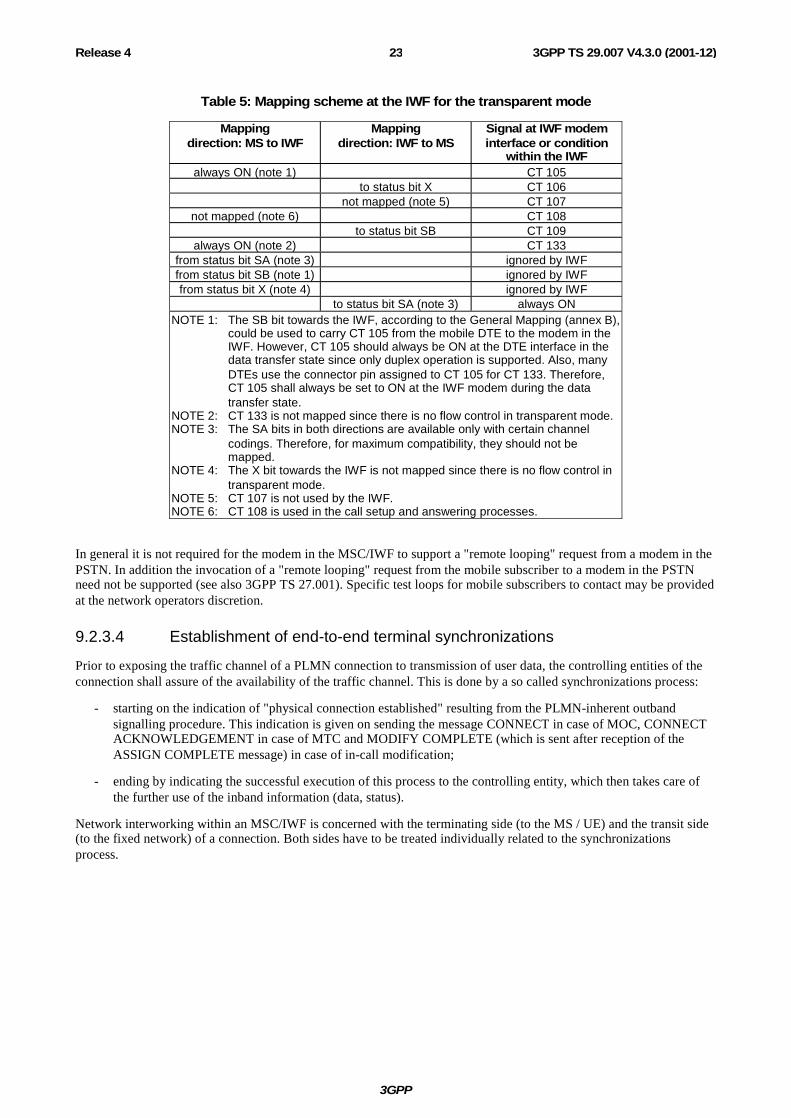
Status bits SA, SB and X can be used to convey channel control information associated with the data bits in the data transfer state. Table 5 shows the mapping scheme between the V.24 circuit numbers corresponding to the V-series DCE functions and the status bits for the transparent mode. It also shows how the unused status bits should be handled. It is derived from the General Mapping scheme described in annex B. A binary 0 corresponds to the ON condition, a binary 1 to the OFF condition.
The transport of these status bits by the various channel codings is described in 3GPP TS 44.021 and 48.020 for GSM. For UMTS refer to 3GPP TR 23.910.
NOTE Although the interface to the modem is described in terms of V.24 interchange circuit functions, this does not imply that such circuits need to be physically realised.
3GPP
3GPP TS 29.007 V4.3.0 (2001-12)23Release 4
Table 5: Mapping scheme at the IWF for the transparent mode
Mapping direction: MS to IWF
Mapping direction: IWF to MS
Signal at IWF modem interface or condition
within the IWF always ON (note 1) CT 105
to status bit X CT 106 not mapped (note 5) CT 107
not mapped (note 6) CT 108 to status bit SB CT 109
always ON (note 2) CT 133 from status bit SA (note 3) ignored by IWF from status bit SB (note 1) ignored by IWF from status bit X (note 4) ignored by IWF
to status bit SA (note 3) always ON NOTE 1: The SB bit towards the IWF, according to the General Mapping (annex B),
could be used to carry CT 105 from the mobile DTE to the modem in the IWF. However, CT 105 should always be ON at the DTE interface in the data transfer state since only duplex operation is supported. Also, many DTEs use the connector pin assigned to CT 105 for CT 133. Therefore, CT 105 shall always be set to ON at the IWF modem during the data transfer state.
NOTE 2: CT 133 is not mapped since there is no flow control in transparent mode. NOTE 3: The SA bits in both directions are available only with certain channel
codings. Therefore, for maximum compatibility, they should not be mapped.
NOTE 4: The X bit towards the IWF is not mapped since there is no flow control in transparent mode.
NOTE 5: CT 107 is not used by the IWF. NOTE 6: CT 108 is used in the call setup and answering processes.
In general it is not required for the modem in the MSC/IWF to support a "remote looping" request from a modem in the PSTN. In addition the invocation of a "remote looping" request from the mobile subscriber to a modem in the PSTN need not be supported (see also 3GPP TS 27.001). Specific test loops for mobile subscribers to contact may be provided at the network operators discretion.
9.2.3.4 Establishment of end-to-end terminal synchronizations
Prior to exposing the traffic channel of a PLMN connection to transmission of user data, the controlling entities of the connection shall assure of the availability of the traffic channel. This is done by a so called synchronizations process:
- starting on the indication of "physical connection established" resulting from the PLMN-inherent outband signalling procedure. This indication is given on sending the message CONNECT in case of MOC, CONNECT ACKNOWLEDGEMENT in case of MTC and MODIFY COMPLETE (which is sent after reception of the ASSIGN COMPLETE message) in case of in-call modification;
- ending by indicating the successful execution of this process to the controlling entity, which then takes care of the further use of the inband information (data, status).
Network interworking within an MSC/IWF is concerned with the terminating side (to the MS / UE) and the transit side (to the fixed network) of a connection. Both sides have to be treated individually related to the synchronizations process.

3GPP
3GPP TS 29.007 V4.3.0 (2001-12)24Release 4
9.2.3.4.1 Terminating side (towards the MS / UE)
9.2.3.4.1.1 GSM Traffic channel types TCH/F4.8 and TCH/F9.6
With respect to the terminating side the procedure is as follows:
- sending of synchronizations pattern 1/OFF (all data bits"1"/all status bits "OFF") to the MS using the RA1/RA2 rate adaptation function. In multislot transparent operation, the synchronisation pattern sent is 1/OFF with the exception of the bit positions S1, first X, S3, and S4 which contain the substream number and multiframe alignment pattern (Ref. 3GPP TS 44.021);
- searching for detection of the synchronizations pattern from the MS within valid V.110 frames, and in multislot operation, also searching for the multiframe alignment pattern "0000 1001 0110 0111 1100 0110 1110 101" (Ref. to 3GPP TS 44.021) in bit position S4 and substream numbers in bit positions S1, first X, and S3. This implies that the E1, E2 and E3 bit of the V.110 frame shall be checked for the appropriate user rate in order to distinguish the synchronization pattern from the BSS idle data frame;
- timer T (= 500 ms) is started for each of the allocated traffic channel(s) of the call on receipt of the synchronizations pattern from the MS;
- when the frame alignment pattern and, in case of multislot operation, the multiframe alignment pattern have been recognized as a steady state, the MSC/IWF continues sending the synchronizations patterns to the MS until a timer T expires.
9.2.3.4.1.2 GSM Traffic channel type TCH/F14.4
With respect to the terminating side the procedure is as follows:
- sending A-TRAU frames with the data rate set in the bits C1-C4 (TS 48.020) and data bits set to one, sending the multiframe structure with the alignment pattern (bit M1) and with the status bits OFF (bit M2) and, in a multislot case, sending substream numbers (bit M2);
- searching for the detection of the multiframe alignment pattern "0000 1001 0110 0111 1100 0110 1110 101" (TS 44.021) in the bit M1 and, in a multislot case, searching for substream numbers in the bit M2. (Any 5 bit sequence in the multiframe alignment pattern is unique, i.e. the multiframe alignment can take place by recognition of five successive M1 bits);
- timer T (= 500 ms) is started for each of the allocated traffic channel(s) of the call on receipt of the synchronizations pattern from the MS;
- when the frame alignment pattern and the multiframe alignment pattern have been recognized as a steady state, the MSC/IWF continues sending the synchronizations patterns to the MS until a timer T expires.
9.2.3.4.1.3 UMTS User Plane
The IWF does not send any frame down link until the modem connection has been established and the modems have synchronised. Thereafter the IWF through connects, mapping data from the fixed network side onto frames that are sent toward the MS, and mapping data in the received frames to the fixed network side.
9.2.3.4.2 Transit side (towards the fixed network)
With respect to the transit side the procedure is as follows:
- at the start of timer T for each of the allocated traffic channel(s) of the call, circuit 108 to the selected modem associated with the connection will be switched from the "OFF" to "ON" condition, thus initiating the establishment of the modem connection. In the case of mobile originated calls, this initiates the auto calling sequence and after signalling, calling tone according to V.25 shall be generated by the modem in the IWF;
- the interchange circuits towards the modem (with the exception of CT108) are held in the OFF condition until timer T expires, when they are switched to ON;

3GPP
3GPP TS 29.007 V4.3.0 (2001-12)25Release 4
- from this time, after the expiration of the timer T of every allocated traffic channel, the information on CT106 and CT109 from the IWF Modem are directly mapped to the SB and X bits toward the MS. For TCH/F14.4 the SB and X bits are mapped to the M2 multiframe bits according to 3GPP TS 44.021. The IWF is allowed to map CT104 to the data bits sent towards the MS and to map data bits received from the MS to CT103.
9.2.3.5 Network Independent Clocking (NIC)
The network independent clocking function applies only to GSM. It is invoked by the VMSC/IWF when the service requested (MO or MT) is 3,1 kHz Ex PLMN and synchronous. The above rule applies irrespective of the information contained in the 3GPP TS 24.008 setup message regarding NIC. For all other services NIC is not used.
Within the GSM network the coding of the values for bits associated with NIC is specified in 3GPP TS 44.021/48.020. In the forward (transmitting) direction the multiframes shall be coded in exact accordance with that specified in those GSM specifications. Bit E6 is set to "1" in alternate modified V.110 frames at the transmitter. However, the use of this bit at the receiver for monitoring frame synchronization, or any other purpose, is not specified and is left to the discretion of the implementer.
A "perfect linear block Code" is used in C1-C5, whose error correction properties may be utilized in the receiver, in order to ensure reliable operation of NIC.
The NIC sending function shall recognize when the difference between the applicable clock speed of the GSM network and the interface speed generates a positive or negative whole bit requirement. When this positive or negative condition occurs, the NIC codewords specified in 3GPP TS 44.021 are used to transport this condition to the receiving NIC function. Transmission of the codeword shall clear the positive or negative condition related to that codeword at the sending function. The sending function shall not send more than one positive or negative compensation within a contiguous period of time corresponding to 10 000 user data bits minus the maximum NIC code framing delay (e.g. in the case of TCH/F2.4, TCH/F4.8 or TCH/F9.6, the number of user data bits necessary to make up an even number of V.110 frames between compensation). NIC compensation is coded in two V.110 frames in the case of TCH/F2.4, TCH/F4.8 or TCH/F9.6 and in one multiframe in the case of TCH/F14.4. This results from the requirements to compensate for maximum clock differences of ±100 parts per million. If the receiving function receives NIC compensations in the average more often than a contiguous period of time corresponding to 10000 user data bits, there is no guarantee that data will not be lost.
The NIC receiving function shall provide the capability to support the compensation requirements of the sending function. This compensation is managed by manipulating the clock speed of the interface, within the standard constraints of that interface.
Overall, the compensation functions shall be capable of managing clock tolerances of ±100 parts per million.
Action on loss of synchronization.
If five consecutive NIC multiframes in the V.110 frame have incorrect framing bit values in E7 or if the A-TRAU multiframe synchronisation is lost, the receiver shall stop applying clocking compensation to the received data. Resynchronization will be attempted and compensation will resume when synchronization is achieved.
9.2.4 Non-transparent service support The protocol stacks for non-transparent services are specified in 3GPP TR 43.010 (GSM) and in 3GPP TR 23.910 (UMTS). Both of the systems use the Radio Link Protocol (RLP) specified in 3GPP TS 24.022.
In UMTS, the non-transparent services are based in the Iu User Plane protocol specified in 3GPP TS 25.415.
In GSM the corresponding necessary support concerning the rate adaptation scheme shall be utilized on the BSS-MSC link as identified in 3GPP TS 48.020.

3GPP
3GPP TS 29.007 V4.3.0 (2001-12)26Release 4
For the non-transparent service support the MSC/IWF will select the modem and speed based on the Compatibility information contained in either the call set-up or call confirmed message, reference subclauses 9.2.1 and 9.2.2. Where the Modem Type indicated is autobauding type 1, the MSC/IWF may select any speed and modem type according to what it can negotiate with the remote modem. In this case User Rate and Fixed Network User Rate, if present, has no meaning.
9.2.4.1 Structure of the MSC/IWF for UMTS
The transmission towards the RNC is based on AAL2. The Iu UP is used in the support mode. The RLP/L2R extends to the MS.
MODEM
ATM
AAL2
Iu UP
RLPL2R
Figure 7: Structure of MSC/IWF
9.2.4.2 Structure of the MSC/IWF for GSM
The rate adaptation process will be the same as for the transparent case (see figure 5), except that a TCH/F43.2 channel coding is also supported. From MSC/IWF's perspective a TCH/F43.2 EDGE configuration is identical to a multislot 3×TCH/F14.4 configuration.
3GPP TR 43.010 identifies the protocol layer structures for the non-transparent case, the physical layer to the PSTN is provided by means of a modem.
9.2.4.3 Re-constitution of user data
3GPP TS 24.022 refers to the frame of user data in the radio link protocol. The layer 2 relay functions in the MS and the MSC/IWF (identified in 3GPP TR 43.010) contain the mechanism for packing and unpacking the user data into the L2R protocol data units.
9.2.4.4 Layer 2 relay functionality
Specific functionality is required of the L2R dependant upon the service which is being requested to be supported. The selection of the appropriate L2R function will be determined by the MSC/IWF on the basis of the bearer capability information signalled in either the call set-up request, or call confirmation messages. The prime information element being transparent or non transparent service indication. In addition the particular L2R function will be selected on the basis of the users layer 2 indication - type of protocol to be terminated and mode of flow control to be applied (see appropriate clauses of the 3GPP TS 27 series).
The specific interaction between the L2R function and the RLP function and the L2R frame structure will be the same as that detailed in the annex to the appropriate 3GPP TS 27 series.
9.2.4.5 In band signalling mapping flow control
This entails the L2R function providing the means of controlling and responding to flow control functions of the modem plus any synchronization requirements related to flow control. For asynchronous services a specific rule applies for flow control (see 3GPP TS 27.001).
The flow control function chosen will be dependent upon the information contained or not contained in the "user information layer 2" information element of the PLMN BC received from the MS.
If flow control is provided, irrespective of the type used the L2R function shall:
(a) provide immediate indication of flow control to the fixed network on receipt of flow control request from the MS; and/or
3GPP
3GPP TS 29.007 V4.3.0 (2001-12)27Release 4
(b) provide immediate indication of flow control to the MS on receipt of flow control request from the fixed network i.e. in the next available L2R status octet to be transmitted.
Where in-band (X-on/X-off) flow control is in use, then the X-on/X-off characters will not be passed across the radio interface.
For outband flow control refer to subclause 9.2.4.9.
If no flow control is provided, the involved end systems are responsible for performing in-band flow control on their own by taking into account the buffer capacity of the MSC/IWF stated below.
9.2.4.5.1 Conditions requiring flow control towards the fixed network
The L2R function will initiate flow control - if flow control is present - in the following circumstances:
1) the transmit buffer reaches a preset threshold (BACK PRESSURE);
2) the L2R function receives an explicit "flow control active" indication.
No flow control initiation/removal will take place at the L2R function and loss of data may occur if no flow control is provided.
On removal of buffer congestion or receipt of L2R "flow control inactive" the flow control will be removed.
9.2.4.5.2 Conditions requiring flow control towards the MS
The L2R function will transmit to the MS an explicit "flow control active indication" if flow control is provided in the following circumstances:
1) if the receive buffer from the radio side reaches a preset threshold (BACK PRESSURE);
2) if a flow control indication is received from the fixed network customer. On receipt of this flow control indication, transmission of data from the receive buffers towards the fixed network terminal is halted.
On removal of the buffer congestion or fixed network flow control indication, the L2R function will send a "flow control inactive" indication towards the MS. In addition, for the fixed network indication, transmission of data from the receive buffers will be restarted.
If no flow control is provided at the L2R function, no flow control initiation/removal will take place by the MSC/IWF. Data might be lost without any indication by the MSC/IWF to the end systems involved.
9.2.4.6 Data buffers
9.2.4.6.1 Transmit buffers (towards MS)
Incoming data from the fixed network customer shall be buffered such that if the MSC/IWF is unable to transfer data over the radio path the data is not lost.
The buffer shall be capable of holding the data. Its size is up to the implementers. When the buffer is half full flow control towards the fixed network shall be initiated if flow control is provided as per subclause 9.2.4.5.1.
9.2.4.6.2 Receive buffers (from MS)
Incoming data from the MS is buffered such that if the fixed network terminal is unable to accept the data then it is not lost.
The buffer shall be capable of holding the data. Its size is up to the implementers. When the buffer becomes half full, the L2R function will send a "flow control active" indication towards the MS if flow control is provided at the L2R function, as per subclause 9.2.4.5.2.

3GPP
3GPP TS 29.007 V4.3.0 (2001-12)28Release 4
9.2.4.7 Transportation of the Break condition
The "BREAK" condition shall be recognized by the L2R function and passed immediately to the MS. The L2R will generate a "BREAK" condition towards the fixed network on receipt of a break indication from the MS. The action of the "BREAK" on the L2R transmit and receive and the length of the "BREAK" signal to be generated towards the fixed network is described in 3GPP TS 27.002.
9.2.4.8 In band signalling mapping modem status information
Status information is carried between the modem in the IWF and the terminal adaptation function in the MS by the L2R function. The L2RCOP entity transfers interface status information between L2Rs via the status octets SA, SB and X in L2RCOP-PDUs (3GPP TS 27.002). Table 6 shows the mapping scheme between the V.24 circuit numbers corresponding to the V-series DCE functions and the status bits for the non-transparent mode. It also shows how the unused status bits should be handled. It is derived from the general mapping scheme described in annex B. A binary 0 corresponds to the ON condition, a binary 1 to the OFF condition.
NOTE Although the interface to the modem is described in terms of V.24 interchange circuit functions, this does not imply that such circuits need to be physically realised.
Table 6: Mapping scheme at the IWF for the non-transparent mode
Mapping direction: MS to IWF
Mapping direction: IWF to MS
Signal at IWF modem interface or condition within
the IWF always ON (note 1) CT 105
to status bit X (notes 4, 7) CT 106 (note 7) not mapped (note 5) CT 107
not mapped (note 6) CT 108 to status bit SB CT 109
from status bit X (note 8) CT 133 (notes 3, 8) from status bit SA (note 2) ignored by IWF from status bit SB (note 1) ignored by IWF
to status bit SA (note 2) always ON NOTE 1: The SB bit towards the IWF, according to the General Mapping (annex B), could be
used to carry CT 105 from the mobile DTE to the modem in the IWF. However, CT 105 should always be ON at the DTE interface in the data transfer state since only duplex operation is supported. Also, many DTEs use the connector pin assigned to CT 105 for CT 133. Therefore, CT 105 shall always be set to ON at the IWF modem during the data transfer state.
NOTE 2: The SA bits (both directions) are not mapped since CTs 107 and 108 are handled locally (notes 5 and 6).
NOTE 3: The condition of CT 133 (or other flow control mechanism) may also be affected by the state of the L2R transmit buffer (towards the MS) in the IWF and the state of RLP (RR/RNR).
NOTE 4: The condition of status bit X towards the MS may also be affected by the state of the L2R receive buffer (from the MS) in the IWF.
NOTE 5: CT 107 is not used by the IWF. NOTE 6: CT 108 is used in the call setup and answering processes. NOTE 7: For inband flow control, CT 106 is not mapped and the status bit X towards the MS
is controlled by the reception of XON and XOFF characters from the modem. NOTE 8: For inband flow control, changes in the condition of the status bit X from the MS
result in the sending of XON or XOFF to the modem. CT 133 is always set to ON.
3GPP
3GPP TS 29.007 V4.3.0 (2001-12)29Release 4
9.2.4.9 Support of out-band flow control
Out-band flow control in case of the asynchronous bearer service requires V.42 functionality in the modems in the MSC/IWF and the fixed network.
If this functionality is requested by the MS but cannot be provided by the MSC/IWF or the remote (fixed network) modem for any reason, the call shall be supported without V.42 functionality (fall back to the non-error correction mode according to V.42).
This implies that no flow control initiation/removal (refer to subclause 9.2.4.5.1) is possible towards the fixed network. In this case the L2R transmit buffers in the IWF (towards the MS, refer to subclause 9.2.4.6.1) shall overbridge temporary throughput problems on the radio interface and the case where the MS initiates flow control. The IWF however shall release the connection if an overflow of these buffers occurs.
9.2.4.10 Establishment of end-to-end terminal synchronizations
Prior to exposing the traffic channel of a PLMN connection to transmission of user data, the controlling entities of the connection shall assure of the availability of the traffic channel. This is done by a so called synchronization process:
- starting on the indication of "physical connection established" resulting from the PLMN-inherent outband signalling procedure. This indication is given on sending the message CONNECT in case of MOC, CONNECT ACKNOWLEDGEMENT in case of MTC and MODIFY COMPLETE (which is sent after reception of the ASSIGN COMPLETE message) in case of in-call modification;
- ending by indicating the successful execution of this process to the controlling entity, which then takes care of the further use of the in-band information (data, status).
Network interworking within an MSC/IWF is concerned with the terminating side (to the MS) and the transit side (to the fixed network) of a connection. Both sides shall be treated individually related to the synchronization process.
9.2.4.10.1 Terminating side (towards the MS / UE)
With respect to the terminating side the procedure in GSM is as follows:
- reception of V.110 or A-TRAU frames on all allocated traffic channels for the call is required before the MSC/IWF shall reply with an RLP-UA frame to the MT's RLP link establishment request (if the MSC/IWF initiates the RLP link establishment, reception of V.110 frames or A-TRAU on all allocated traffic channels for the call shall be detected first);
- waiting for the RLP link establishment by the MT (in addition the MSC/IWF may initiate the RLP establishment).
In UMTS at the IWF, the synchronisation of modems on the transit network is performed after establishment of the physical connection. The RLP establishment may be initiated by the IWF, but is normally initiated by the MS. If the modems synchronise before the RLP has been established, the IWF stores the information received from the other modem in the L2R buffers.
9.2.4.10.2 Transit side (towards the fixed network)
Depending upon implementation - CT108 will be turned ON to enable the autocalling/autoanswering function of the selected modem either when the RLP has been established or in parallel to RLP establishment. If CT 108 is turned ON in parallel to the RLP establishment, the modem connection may be established before the RLP is established. In this case, data received from the transit side during RLP establishment shall be stored within the L2R buffers until the RLP establishment at the terminating side has been finished. When the RLP has been established, the information from/to the RLP including status changes will be mapped by the L2R entity applicable to the particular bearer capability. After signalling, for MO calls, calling tone according to V.25 shall be generated by the modem in the IWF.

3GPP
3GPP TS 29.007 V4.3.0 (2001-12)30Release 4
9.2.4.11 Data compression
When data compression is invoked within a non-transparent bearer service, interworking to the fixed network is realized as follows.
The PLMN BC is used to indicate the interworking modem type and user rate. The modems shall try to negotiate data compression and flow control. If negotiation of data compression fails in the fixed network, the call continues with data compression between MS and IWF only.
9.2.4.12 Service level up and down grading
Service level up and down grading is only applicable for GSM. If the value of the RLP parameter "UP signalling" is negotiated to 1, the IWF shall send a suggestion to the MS to initiate an upgrading whenever the following condition holds:
The IWF:
1) is receiving user data from the fixed network side at a higher rate than the current AIUR; or
2) in symmetrical calls only, can send user data towards the fixed network side at a higher rate than the current AIUR.
When the above condition does not hold, the IWF sets the value of the UP bit continuously to 0. When the condition above does hold, the IWF indicates the number of traffic channels to upgrade by, by sending that number of 1s between two consecutive 0s in the UP bit sequence. This indication is not repeated since the FCS protects it. For instance, if the current number of traffic channels is two and an upgrading to four traffic channels is suggested, the UP bit sequence shall be ..01100... How the IWF detects the condition and additional details for setting and resetting of the UP bit, e.g., hysteresis levels, may depend on implementation. NOTE: From MSC/IWF's perspective a TCH/F28.8 or TCH/F43.2 EDGE configuration is identical to a multislot 2×TCH/F14.4 or 3×TCH/F14.4 configuration. In this case, rather than suggesting the number of channels to add, the IWF suggests a number of 14.4 substreams to add and therefor a factor of 1/2 or 1/3 shall be applied to the suggested increase when the assigned up link channel is TCH/F28.8 or TCH/F43.2 respectively.
9.2.5 DTE/DCE interface (Filtering)
The DTEs taken into account for the PLMN at the MS side conform to ITU-T's DTE/DCE interface specifications, which assume basically an error-free environment, i.e.:
- limited distance, point-to-point local interconnection of the interface circuits for data and status;
- steady state signalling.
The envisaged use of these DTE's in the PLMN environment leads to the exposure of these "interconnections" - which may, in the ISDN case, lead to the ISDN Rate Adaptation rather than to a Modem in the MSC/IWF - to the PLMN Radio Channel. To assure proper operation even under these conditions appropriate measures shall be taken. In the "non-transparent case" the RLP satisfies the requirement for both data and status lines. In the "transparent" case, the:
- data line aspects shall be dealt with end-to-end between the users; while
- status line aspects are of concern to the network which are dealt with in the following.
The use of the channel control information for the remote control of the DTE/DCE control interchange-circuits between the MS and the MSC/IWF (the conveyance of which is supported by the rate adaptation scheme adopted for PLMN application) requires alignment to the particular transmission occurrences in the traffic channel to be taken into account within the PLMN. In principle this can be best achieved by:
- relying only on the PLMN outband signalling as far as connection control is concerned;
- eliminating the dependence upon the transmission of channel control information via the radio link.
Support for this strategy is given to a certain extent by the confinement of PLMN data connections to:
- full duplex operation (no turning round of the connection is required);

3GPP
3GPP TS 29.007 V4.3.0 (2001-12)31Release 4
- switched service (demand access);
- mapping of connection-control relevant conditions of the DTE/DCE control interchange-circuits to/from outband PLMN signalling according to 3GPP TS 24.008 after successful traffic channel synchronization;
- flow control by a network entity supported only in non-transparent mode;
- support of connections with the same user data rate only (no TA to TA end-to-end flow control in case of transparent mode).
The only DTE/DCE control interchange-circuit conditions, which actually are not covered by the above confinements, are the indications of readiness for data transmission, i.e. CT106/109 in case of V.-series interface and I-circuit of X.-series interface. As the effect of a condition change of the afore-mentioned DTE/DCE interchange-circuits depends on the:
- phase within the course of the connection;
- direction of change (ON-OFF or OFF-ON).
The required precaution to be applied (Filtering) shall be determined individually in view of:
- function deduced from the change;
- resilience of the connection needed;
- error condition possibly invoked due to a delay in performing the condition change of the control interchange circuit;
- potential loss of performance in connection usage.
The details of the filtering function are laid down in 3GPP TS 27- series. Filtering of channel control information is only relevant at the MS side in the transparent mode of operation.
9.3 Interworking Alternate Speech / Facsimile Group 3 Calls
9.3.1 General
The procedure for the alternate speech/facsimile group 3 services is invoked at MS-MSC link during the call set-up phase. This service is invoked by indication of repeated bearer capability information elements in the setup message and/or call confirmed message respectively (preceded by a repeat indicator "circular"), one indicating speech and the other indicating facsimile group 3. The facsimile service requested will be indicated by the information transfer capability "facsimile group 3", as for a normal single call. The bearer capability first indicated i.e. speech or facsimile group 3 determines the first selection required of the network by the subscriber. Depending on the type of service requested and direction of call establishment (M0/MT, see relevant clauses of 3GPP TS 27 series) low layer and high layer capabilities may also be included. The MSC/IWF will perform both compatibility checking and subscription checking on both sets of capabilities as for normal data calls. If either the subscription check or the compatibility check fails then the call will be rejected. The only exception to this is when TS61/TS62 negotiation takes place, see 3GPP TS 27.001.
The applicable rules for provision of supplementary services are laid down in 3GPP TS 22.004.
The "speech" phase of the call, when invoked is handled by the transcoder and will utilize normal telephony teleservice interworking requirements and mobile network capabilities. This includes any requirements for echo cancellers etc. as indicated in subclause 9.1. The "facsimile group 3" phase of the call, when invoked, shall utilize the appropriate data interworking capability (IWF including modem) and shall use the transparent mobile network capability in GSM or the non-transparent mobile network capability in UMTS.
The network shall provide, for service and operational reasons, a rapid and reliable changeover of capability upon request from the mobile user. This changeover may involve the disabling, by-passing or introduction of particular network functions (e.g. speech coder, modem etc.) and change of the channel configuration on the radio interface. This changeover is initiated on the receipt of the "MODIFY" message (see 3GPP TS 24.008) from the MS. The network itself will not initiate a changeover.

3GPP
3GPP TS 29.007 V4.3.0 (2001-12)32Release 4
9.3.2 Mobile originated PSTN terminated calls The call is set up in the normal manner (but with repeated bearer capability information elements as described in subclause 9.3.1 and handled by the MSC/IWF as indicated in the general clause.
9.3.3 PSTN originated mobile terminated calls
The call set up request for this particular service is performed in a similar manner to that indicated in subclause 9.2 for normal PSTN originated calls.
When multiple MSISDNs are used by the HLR ("Multi-numbering scheme"), one PLMN BC-IE with the ITC value set to "alternate speech/facsimile group 3, starting with speech" is passed to the VLR in the MAP operation "provide roaming number". The VLR stores this information against the MSRN.
When the call arrives at the visited MSC this information is retrieved from the VLR and sent to the MS in the setup message as defined in 3GPP TS 27.001.
If the ITC of the PLMN BC-IE retrieved from the VLR has the value "alternate speech/facsimile group 3, starting with speech" this PLMN BC-IE shall be mapped to two PLMN BC-IEs (preceded by a repeat indicator "circular"), one representing speech, the other representing facsimile group 3. The order in which these two PLMN BC-IEs are sent towards the MS, in the setup message, is a network option.
In order to allow auto answering mode for the facsimile phase (i.e. the call starts automatically with the facsimile phase), the MS can reflect back to MSC the dual Bearer Capability in the Call Confirm message with the BC elements interchanged to those in the original Call Set-up message (i.e. facsimile element first or negotiate to facsimile only, see subclause 9.2.2 and 3GPP TS 27.001). In all other aspects it is handled as indicated for mobile originated.
NOTE: However, the PLMN specific parameters "connection element" and "radio channel requirements" of the retrieved PLMN BC-IE may be modified, or added in line with the principles identified in subclause 9.2.2.
When a single MSISDN is allocated to the subscriber ("single numbering scheme"), the call is handled as described in case b) of subclause 9.2.2. In the "call confirmed" message, however, two PLMN BC-IEs are preceded by a repeat indicator "circular", with the first PLMN BC-IE indicating the initial phase of the connection.
9.4 3G-H.324/M calls over 3,1kHz audio
In case of 3G-H.324/M calls over 3.1kHz audio, the IWF shall provide the V.34 modem modulation and the V.8 procedure with the indication of H.324 support in the call function category of the V.8 handshaking. H.223 & H.245 flow is not terminated in the modem function.
The performance of V.8bis by the modem function is FFS.
9.4.1 Mobile originated multimedia call
9.4.1.1 Call setup
The setup message sent by the MS contains either a multimedia BC-IE indicating a multimedia only call request (i.e. no fallback to speech allowed) or both a speech BC-IE and a 3.1kHz multimedia BC-IE to indicate the support of a fallback to speech (ref. to TS 27.001 and TS 24.008).
The MSC shall not accept a requested service to which the user has no subscription. On the condition the user has the required subscriptions (i.e. to multimedia and/or speech) the following applies:
- in case of a multimedia only BC-IE the MSC may accept the setup as such or with modifications sent to the MS in the call proceeding message (ref. to TS 27.001);
- in case of both a speech BC-IE and a 3.1kHz multimedia BC-IE the MSC may either accept the possibility of a fallback to speech by responding with two BC-IEs or with no BC-IEs or turn the call to a speech call by sending only a speech BC-IE in the call confirm message or turn the call to a multimedia only call by sending only a multimedia BC-IE in the call confirm message (Ref. to TS 27.001).
3GPP
3GPP TS 29.007 V4.3.0 (2001-12)33Release 4
The IWF V.34 modem shall initiate the ITU-T V.8 handshaking and indicate the support of H.324/M in the call function category of the V.8 handshaking. If the called party's modem does not indicate a H.324 support in its V.8 inband signalling response, the IWF may clear the call. If the called party responds with a modem answering tone but there is no V.8 response at all, the IWF shall clear the call.
If FNUR = 33.6 kbit/s is agreed on in the setup, the IWF shall configure its V.34 modem to operate in automode with an upper data rate limit of 33.6 kbit/s and a lower data rate limit of 28.8 kbit/s. If the modems handshake to 31.2 or 28.8 kbit/s, the MSC shall initiate a MODIFY message (ref. to TS 24.008) to indicate the new data rate to the MS. HDLC flag stuffing or the stuffing mode defined in ITU-T recommendation H.223 (Annexes A, B and C) shall be used to adapt the 31.2 or 28.8 kbit/s data rate to the 33.6 kbit/s traffic channel between the MS and the IWF. In order to be able to use the correct stuffing pattern, the IWF shall detect the stuffing mode patterns exchanged between the multimedia terminals after the traffic channel setup (ref. to ITU-T recommendation H.324). The IWF may start the stuffing immediately after the detection of the used method. In downlink stuffing the IWF inserts stuffing patterns between the H.223 frames. In uplink stuffing the IWF removes stuffing patterns from between the H.223 frames received from the MS. If the MS responds with a MODIFY REJECT message, the MSC shall clear the call.
9.4.1.2 Fallback to speech after setup
If the MSC has accepted the possibility of a fallback to speech and the IWF modem does not recognize the answering tone of the called modem within the expiration of a timer started at the reception of the answer message, the MSC IWF shall initiate an In Call Modification procedure (ref. to TS 24.008) in order to fall back to a speech mode. As a result of the procedure the IWF resource shall be released and a speech channel shall be set up between the calling MS and the fixed network. If the fallback fails e.g. due to a failing In Call Modification procedure, the IWF shall clear the call.
A recommended minimum value for the timer is 3 seconds (ref. to the ITU-T V.25 recommendation).
9.4.2 Mobile terminated multimedia call
9.4.2.1 Call setup
If the user has a subscription to both the multimedia bearer service and the speech teleservice and if the network supports both services and the fallback functionality, the MSC shall send both a multimedia BC-IE and a speech BC-IE in the setup message to the mobile station. If the user has a subscription only to the multimedia bearer service the MSC shall send only a multimedia BC-IE.
In case of both a speech BC-IE and a 3,1 kHz multimedia BC-IE in the setup the mobile station may either accept the possibility of a fallback to speech by responding with two BC-IEs or with no BC-IEs or turn the call to a speech call by sending only a speech BC-IE in the call confirm message or to a multimedia only call (i.e. no fallback to speech allowed) by sending only a multimedia BC-IE in the call confirm message. In case of a multimedia only BC-IE in the setup the MS may accept the setup as such or with modifications sent to the MSC in the call confirm message.
If no service definition is available in the network, the MSC shall send no BC-IE(s) to the mobile station in the call setup. The MSC shall perform a subscription check to the multimedia and/or speech service(s) requested by the mobile station in the call confirm message and shall not accept a requested service to which the user has no subscription.
The IWF V.34 modem shall await the ITU-T V.8 handshaking to be initiated by the calling party's modem and shall recognize the support of H.324 in the call function category of the incoming V.8 handshaking. If the calling party's modem does not indicate a H.324 support in its V.8 inband signalling, the IWF may clear the call. If the calling modem tries to handshake another than V.34 modem scheme, the IWF shall clear the call.
If FNUR = 33.6 kbit/s is agreed on in the setup, the IWF shall configure its V.34 modem to operate in automode with an upper data rate limit of 33.6 kbit/s and a lower data rate limit of 28.8 kbit/s. If the modems handshake to 31.2 or 28.8 kbit/s, the MSC shall initiate a MODIFY message (ref. to TS 24.008) to indicate the new data rate to the MS. HDLC flag stuffing or the stuffing mode defined in ITU-T recommendation H.223 (Annexes A, B and C) shall be used to adapt the 31.2 or 28.8 kbit/s data rate to the 33.6 kbit/s traffic channel between the MS and the IWF. In order to be able to use the correct stuffing pattern, the IWF shall detect the stuffing mode patterns exchanged between the multimedia terminals after the traffic channel setup (ref. to ITU-T recommendation H.324). The IWF may start the stuffing immediately after the detection of the used method. In downlink stuffing the IWF inserts stuffing patterns between the H.223 frames. In uplink stuffing the IWF removes stuffing patterns from between the H.223 frames received from the MS. If the MS responds with a MODIFY REJECT message, the MSC shall clear the call.

3GPP
3GPP TS 29.007 V4.3.0 (2001-12)34Release 4
9.4.2.2 Fallback to speech after setup
If the MSC supports a fallback to speech and the user has a subscription to the speech service and the mobile station accepts the possibility of a fallback to speech in the call confirm message and the IWF modem does not recognize a call tone nor a V.8 Call Indication nor a V.8 Call Menu within the expiration of a timer started at the sending of the ANSam answer tone (i.e. the calling party is not a V.34 modem), the IWF shall initiate an In Call Modification procedure (ref. to TS 24.008) in order to fall back to a speech mode. As a result of the procedure the IWF resource shall be released and a speech channel shall be set up between the called MS and the fixed network. If the fallback fails e.g. due to a missing subscription to speech or a failing In Call Modification procedure, the IWF shall clear the call.
A recommended minimum timer value is 3 seconds (ref. to the ITU-T V.8 recommendation).
9.4.3 Seamless data rate change If the modems change the data rate during an ongoing multimedia call (using the ITU-T V.34 seamless data rate change mechanism), the MSC shall initiate a MODIFY message (ref. to TS 24.008) to indicate the new data rate to the MS. HDLC flag stuffing or the stuffing mode defined in ITU-T recommendation H.223 (Annexes A, B and C) shall be used to adapt the 31.2 or 28.8 kbit/s data rate to the 33.6 kbit/s traffic channel between the MS and the IWF. The stuffing pattern found out during the traffic channel setup (ref. to subclauses Call setup) is used. The IWF may start the stuffing immediately after the detection of the data rate change by the modems.
10 Interworking to the ISDN The interworking to the ISDN is specified on the principle of the network supporting standardized associated signalling protocol as outlined in clause 6, i.e. DSS1 and ISUP. An ISDN not complying with this definition differs - for the purpose of the present document - in that it does not support the compatibility information to that degree necessary for deducing a PLMN Basic Service. These networks will find their reflection in the following where those implications are to be set out.
The calling address sent in a mobile originated call to the ISDN is always the basic MSISDN even if the ISDN user shall use a different MSISDN (multi numbering scheme, see 9.2.2 case a) for a mobile terminated call (call back) as only the basic MSISDN is available at the VLR (see 3GPP TS 29.002).
The scope of this clause is to describe the handling of the content of the Information Elements where "content" is understood to be the value of the parameter fields of the Information Elements, namely BC-IE, HLC and LLC, after the length indicator. For the transport of these Information Elements within the PLMN refer to 3GPP TS 29.002.
The handling of multislot, 14.4kbit/s, or EDGE-related parameter of the call control signalling and the applicability of single- or multislot configurations (refer to 3GPP TS 48.020 and 3GPP TS 44.021) is the same as for the PSTN interworking cases. For multislot, 14.4kbit/s, or EDGE-operations, the MS may also propose to the network to modify the Fixed Network User Rate and Other Modem Type parameters (see 3GPP TS 27.001). In case a transparent service is used, the call shall be released. For a non-transparent service with flow control, the MSC/IWF shall use towards the fixed network the unmodified "fixed network user rate" and shall use the "wanted air interface user rate" towards the mobile station.
10.1 Speech Calls Since at the interworking point the transcoder provides for A-law or µ-law (PCS-1900) PCM at 64 kbit/s, no particular interworking is required. It is anticipated that the ISDN Teleservice Telephony and ISDN Bearer Service speech, respectively would be used. Transmission aspects are covered in 3GPP TS 43.050. Any further requirements are a national matter.
10.2 Data Calls In this case it is assumed that the ISDN bearer service 3,1 kHz audio shall only be interworked by means of a modem pool in the PLMN. If a network operator provides this facility, then the MSC/IWF operation will be similar to that described for interworking to the PSTN.
3GPP
3GPP TS 29.007 V4.3.0 (2001-12)35Release 4
Where the bearer capability information indicates that the call is a circuit switched unrestricted digital call, then the MSC/IWF shall select the appropriate rate adapted ISDN and PLMN bearer services.
10.2.1 Network interworking mobile originated Low layer compatibility checking of the mobile originated call is carried out by the MSC/IWF to determine the appropriate bearer service selection in the ISDN. This will entail the MSC/IWF in mapping appropriately the PLMN BC-IE to the ISDN BC-IE (bearer capability information element). If it is not possible for the MSC/IWF to provide a bearer service match, then the MSC/IWF shall fail the call and indicate the reason to the user.
The MS shall provide further compatibility information (LLC/HLC-IEs) if required for defining end-to-end compatibility.
As well as compatibility checking, subscription checking should be performed.
The selection of the MSC/IWF will be by means of the bearer capability information within the call set up message. The mobile subscriber shall be able to select the unrestricted digital capability, which the MSC/IWF will map to the same capability in the ISDN call set up message. If an interworking point is encountered within the ISDN which does not support this service request, then either a call release message including an appropriate error cause or progress message is returned to the PLMN, indicating that the ISDN network is unable to support the service requested. In the case of a call release message the network shall release the call. In the case of progress message the network releases the call or forwards it (see 3GPP TS 24.008) to the mobile which will release the call.
10.2.2 Network interworking mobile terminated
10.2.2.1 General
This subclause describes the interworking of calls where the calling subscriber can communicate ISDN compatibility information with exhaustive contents for deducing a PLMN Basic Service to a PLMN (gateway MSC/interrogating node) i.e. by means of ISDN signalling.
The GMSC shall perform a mapping of the received Basic Service Information for the transport to the HLR, for details of this transport refer to 3GPP TS 29.002.
Compatibility checking of the low layers of the ISDN originated call is carried out by the MSC/IWF to determine the appropriate bearer service selection in the PLMN. This will entail the MSC/IWF in mapping appropriately the ISDN BC/LLC-IE to the PLMN BC-IE.
As well as compatibility checking, subscription checking should be performed. If either the subscription check or the compatibility check fails then the call will be rejected.
For ISDN originated calls it will not be possible to signal mobile specific requirements e.g. transparent/non transparent, full/half rate channel. Therefore the MSC/IWF shall select a default setting appropriate to the visited PLMN's network capabilities. In general it will be beneficial, where a network supports both full and half rate channels and transparent/non transparent capabilities, to indicate so in the appropriate PLMN BC field of 3GPP TS 24.008. The mobile subscriber has the option to indicate in the call confirmation message a change to this default setting according to the rules specified in 3GPP TS 27.001. The appropriate MSC/IWF shall be selected on the basis of this requirement.
10.2.2.2 Functions in GMSC
At call Set-up, the interrogating node passes in the "send routing information" to the HLR, the ISDN BC, LLC and HLC received in the initial address message. The coding of these parameters shall comply with Q.931 (05/98). For MT calls, and for backward compatibility purposes only, the mapping of the modem type according to ETS 300-102-1 (12/90) shall also be accepted, see note 12 of table 7B.
10.2.2.3 Functions in HLR
According to the contents of the Compatibility Information, i.e. the ISDN BC, LLC and HLC received, the HLR applies one of the following alternatives:

3GPP
3GPP TS 29.007 V4.3.0 (2001-12)36Release 4
1) no ISDN BC is received, or one from which a PLMN Basic Service cannot be deduced with the information Transfer Capability field set to "3,1 kHz audio" but without any associated modem type1 in the ISDN BC and LLC, or without HLC indication of group 3 facsimile. Two cases shall be considered:
a) the called MSISDN has a corresponding PLMN BC-IE stored in the HLR (see option a) of 9.2.2); then the service attached to this number in the HLR tables is applicable and the corresponding PLMN BC-IE is passed to the VLR in "provide roaming number". See figure 6;
b) the called MSISDN has no corresponding PLMN BC-IE stored in the HLR (see option b in 9.2.2). In this case no PLMN BC is passed to the VLR in the "provide roaming number" message.
2) compatibility Information is received from which a PLMN Basic Service can be deduced, i.e. the ITC field in the ISDN BC received is "unrestricted digital" and the fields for the applicable user layer 1 protocol and user rate (except for the 64kbit/s case, see Note 22 Table 7B) are available (either in the ISDN BC or LLC), or the ITC field is "3,1 kHz audio", and a modem type, user rate, etc. is indicated but the HLC does not indicate "facsimile group 3". The received ISDN BC (and possibly LLC plus HLC) is then considered applicable regardless of the kind of MSISDN received (PLMN BC associated or not) and either the equivalent PLMN BC or the original ISDN BC/LLC is sent to the VLR. Additionally in both cases the originally received HLC may also be sent to the VLR, see figure 7.
In exception to this the BC stored in the HLR is regarded valid if one of the following cases applies:
- If ITC = UDI/RDI and User Rate = 32 kbit/s /56 kbit/s and User information layer 1 protocol = V.110, I.460/X.30 and the stored BC indicates FTM, PIAFS or Multimedia.
- If ITC = 3,1 kHz audio and User Rate = 28.8 kbit/s and Modem Type = V.34 and the stored BC indicates Multimedia.
When the HLR interworks with a phase 1 GSM VPLMN (VLR/VMSC), then the HLR shall convert the ISDN BC to the equivalent GSM BC, and forward to the VLR. In this case however no LLC can be forwarded.
3) Compatibility Information is received from which the PLMN Teleservice category Facsimile transmission can be deduced i.e. the ITC field in the ISDN BC received is "3,1kHz audio" and the HLC indicates "facsimile group 3" (see figure 7), the following two cases shall be considered:
a) the called MSISDN has a corresponding PLMN BC stored in the HLR (either stating TS 61 or TS 62). In this case the service attached to the MSISDN in the HLR tables is applicable and the corresponding PLMN BC is passed to the VLR in the "provide roaming number" message, see also subclause 10.3.1.3;
b) the called MSISDN has no corresponding PLMN BC stored in the HLR. In this case the HLR shall forward the appropriate PLMN BC to the VLR in line with the subscribers subscription to Teleservice TS 61 or 62.
For TS 61 the value of the PLMN BC-IE parameter "Information Transfer Capability" shall be set to "alternate speech/facsimile group 3, starting with speech".
In both cases the HLC IE should be passed to the VLR in the "provide roaming number" message.
Alternatively the HLR may forward the originally received ISDN/LLC/HLC, when interworking with a phase 2 GSM VLR or a UMTS VLR, respectively.
4) In the case where Compatibility Information received does not allow for deducing a PLMN Bearer Service but an ISDN BC is received with the ITC field indicating "unrestricted digital", but without the fields indicating applicable "user layer 1 protocol", user rate, etc., neither in the ISDN BC or the ISDN LLC then the following shall apply. The call is managed as for an udi call according to subclause 9.2.2, i.e. either the "multi numbering" or "single numbering" scenario is applied depending on which capability is provided by home PLMN/HLR.
10.2.2.4 Functions in VMSC
At the VMSC, when the incoming call arrives, the LLC/HLC and the PLMN or ISDN BC associated with the MSRN is retrieved from the VLR. LLC and HLC are sent with the PLMN BC in general to the MS at call set-up. In particular, however the following rules apply:
1 "Modem type" in connection with the ITC value "3,1 kHz audio" means hereafter that either an ISDN BC modem type value is present or the autobauding modem function is indicated (see note 16 of table 7B)

3GPP
3GPP TS 29.007 V4.3.0 (2001-12)37Release 4
1) If the Initial Address Message (IAM) contains no ISDN BC and there is no PLMN or ISDN BC/LLC/HLC retrieved from the VLR, the call is handled as subclause 9.2.2 case b.
2) If there is no ISDN BC in the IAM but a PLMN or ISDN BC/LLC/HLC was signalled in the "provide roaming number" message, the retrieved PLMN or ISDN BC/LLC/HLC applies.
3) If there is an ISDN BC in the IAM with the ITC field set to "3,1 kHz audio" but without any associated modem type or indication of facsimile group 3 in the HLC, the PLMN or ISDN BC/LLC/HLC retrieved from the VLR is considered as applicable when it exists. If no PLMN or ISDN BC is retrieved from the VLR, the call is handled as in subclause 9.2.2 case b.
4) If the ISDN BC received in the IAM has the ITC field set to the value "unrestricted digital information" and the fields for the applicable "user layer 1 protocol" and "user rate" (except for the 64kbit/s case, see note 22 table 7B) are available (either in the ISDN BC or ISDN LLC), or if 3,1 kHz audio and a modem type is indicated, this ISDN BC is applicable regardless of what has been retrieved from the VLR. In this case the ISDN BC shall be mapped to an appropriate PLMN BC (refer to table 7B).
In exception to this the BC stored in the VLR is retrieved and send to the MS if one of the following cases applies:
If ITC = UDI/RDI and User Rate = 32 kbit/s /56 kbit/s and User information layer 1 protocol = V.110, I.460/X.30 and the stored BC indicates FTM, PIAFS or Multimedia.
If ITC = 3,1 kHz audio and User Rate = 28,8 kbit/s and Modem Type = V.34 and the stored BC indicates Multimedia.
5) If the ISDN BC received in the IAM has the ITC field set to the value "3,1kHz audio" and a HLC "facsimile group 3" is indicated, the PLMN BC retrieved from the VLR is applicable when it exists. If a PLMN BC-IE with the parameter "information transfer capability" set to "alternate speech/facsimile group 3, starting with speech" (stating TS61) is retrieved from the VLR, this shall be mapped to two PLMN BC-IE preceded by a repeat indicator, one representing speech, the other representing facsimile group 3.
When no PLMN BC is retrieved from the VLR, either two PLMN BCs preceded by a repeat indicator (stating Teleservice TS 61), or a single PLMN BC-IE (stating TS 62), are sent in the setup message, depending whether TS 61 or TS 62 is subscribed (see also subclause 10.3.1.3).
In case of TS 61, the order in which the two PLMN BC-IEs are sent towards the MS, in the setup message, is a network option.
6) If the ISDN BC received in the IAM has a ITC value "unrestricted digital information" but without applicable "user layer 1 protocol" and "user rate", etc. fields, neither in the ISDN BC nor ISDN LLC, then the PLMN or ISDN BC/LLC retrieved from the VLR is applicable, if available otherwise subclause 9.2.2 case b applies.
In case of an ISDN BC/LLC/HLC was attached to the MSRN this shall be mapped to an appropriate PLMN BC (refer to table 7B). However in both cases (PLMN or ISDN BC attached) the PLMN specific parameters of the PLMN BC-IEs may be added/modified in line with procedures identified in subclause 9.2.2.
7) If the ISDN BC received in the IAM has the ITC field set to the value "Speech" and the ITC field of the ISDN BC received with the IAM differs from the ITC field of the BC stored in the VLR for this call, the VLR BC/LLC/HLC is considered applicable. If no PLMN or ISDN BC is retrieved from the VLR, the call is handled as in subclause 9.2.2 case b.
In all cases when no PLMN or ISDN BC is retrieved from the VLR and no ISDN Compatibility information allowing deduction of a PLMN Bearer Service is available, then no PLMN BC is inserted by the VMSC and subclause 9.2.2 case b applies.
The mapping between PLMN and ISDN BCs is shown in table 7.

3GPP
3GPP TS 29.007 V4.3.0 (2001-12)38Release 4
10.2.2.5 Call Flows
VLRMS VMSC HLR
Call Conf.
IN
Setup
(BCgk)
(BC' gk)
(BC''gk)
(BC' gk)
SIFICSU
Comp. Call
PRN
(MSRN)
IAM
SRI
IAM
(1)
(2)
(3,1 kHz,MSRN)
(MSRN)(MSRN)
(3,1 kHz,MSISDNk)
(3,1 kHz,MSISDNk)
Abbreviations: see figure 2. NOTE: (1) Some parameters of BCgk may be provided/modified according to the MSC's capabilities/preferences.
See subclause 9.2.2. (2) In the "Call Confirm" message, the MS may modify some parameters of the PLMN BC. See
subclause 9.2.2.
Figure 8: Call Flow for a mobile terminated, ISDN originated call where compatibility information provided are not exhaustive for deducing a PLMN Bearer Service,
but Information Transfer Capability = 3,1 kHz audio, no modem type and no HLC IE indicating facsimile group 3 HLR stores PLMN BC against MSISDN number multi-numbering scheme
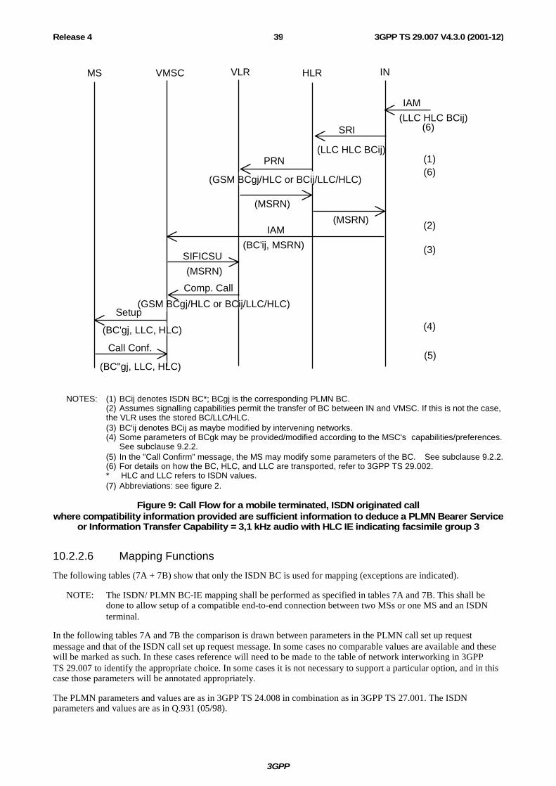
3GPP
3GPP TS 29.007 V4.3.0 (2001-12)39Release 4
VLRMS VMSC HLR
Call Conf.
IN
Setup
SIFICSU
Comp. Call
PRN
(MSRN)
IAM
SRI
IAM
(6)
(5)
(MSRN)
(MSRN)
(LLC HLC BCij)
(LLC HLC BCij)
(BC'ij, MSRN)
(1)(6)
(2)
(3)
(4)
(GSM BCgj/HLC or BCij/LLC/HLC)
(BC'gj, LLC, HLC)
(BC''gj, LLC, HLC)
(GSM BCgj/HLC or BCij/LLC/HLC)
NOTES: (1) BCij denotes ISDN BC*; BCgj is the corresponding PLMN BC. (2) Assumes signalling capabilities permit the transfer of BC between IN and VMSC. If this is not the case,
the VLR uses the stored BC/LLC/HLC. (3) BC'ij denotes BCij as maybe modified by intervening networks. (4) Some parameters of BCgk may be provided/modified according to the MSC's capabilities/preferences.
See subclause 9.2.2. (5) In the "Call Confirm" message, the MS may modify some parameters of the BC. See subclause 9.2.2. (6) For details on how the BC, HLC, and LLC are transported, refer to 3GPP TS 29.002.
* HLC and LLC refers to ISDN values. (7) Abbreviations: see figure 2.
Figure 9: Call Flow for a mobile terminated, ISDN originated call where compatibility information provided are sufficient information to deduce a PLMN Bearer Service
or Information Transfer Capability = 3,1 kHz audio with HLC IE indicating facsimile group 3
10.2.2.6 Mapping Functions
The following tables (7A + 7B) show that only the ISDN BC is used for mapping (exceptions are indicated).
NOTE: The ISDN/ PLMN BC-IE mapping shall be performed as specified in tables 7A and 7B. This shall be done to allow setup of a compatible end-to-end connection between two MSs or one MS and an ISDN terminal.
In the following tables 7A and 7B the comparison is drawn between parameters in the PLMN call set up request message and that of the ISDN call set up request message. In some cases no comparable values are available and these will be marked as such. In these cases reference will need to be made to the table of network interworking in 3GPP TS 29.007 to identify the appropriate choice. In some cases it is not necessary to support a particular option, and in this case those parameters will be annotated appropriately.
The PLMN parameters and values are as in 3GPP TS 24.008 in combination as in 3GPP TS 27.001. The ISDN parameters and values are as in Q.931 (05/98).

3GPP
3GPP TS 29.007 V4.3.0 (2001-12)40Release 4
Table 7A: Comparable setting of parameters in PLMN and ISDN: Mobile Originated
Octet PLMN BC parameter value Octet ISDN BC parameter value 1 Bearer Capability IEI 1 Bearer Capability IEI 2 Length of BC contents 2 Length of BC contents 3 #7..6
Radio channel requirement half rate channel full rate channel dual, full, rate preferred dual, half rate preferred
No comparable field
3 #5
Coding Standard GSM standard coding
3 #7..6
Coding Standard CCITT standardized coding
3 #4
Transfer mode circuit mode packet mode (note7)
4 #7..6
Transfer mode circuit mode packet mode
3 #3..1
Information transfer capability speech unrestricted digital 3,1 kHz audio ex PLMN facsimile group 3 (note 1) other ITC (see octet 5a)
3 #5..1
Information transfer capability speech unrestricted digital 3,1 kHz audio 3,1 kHz audio no comparable value
5a #7..6
Other ITC restricted digital
(note 18)
4 #7
Compression (note 14) data compression allowed data compression not allowed
No comparable field
4 #6..5
Structure SDU integrity unstructured
4a #7..5
Structure (note 4)
4 #4
Duplex mode half duplex full duplex
5d #7
Duplex mode half duplex full duplex
4 #3
Configuration point to point
4a #4..3
Configuration (note 4)
4 #1
Establishment demand
4a #2..1
Establishment (note 4)
4 NIRR (note 12) no meaning Data ≤ 4.8kbit/s, FR nt, 6kbit/s radio interface is requested
No comparable field
5 #5..4
Rate adaptation no rate adaptation (note 2) V.110, I.460/X.30 rate adaptation CCITT X.31 flag stuffing No comparable value (note 11) No comparable value (note 11) No comparable value (note 11) other rate adaptation (see octet 5a)
5 #5..1
User information layer 1 protocol no comparable value CCITT standardized rate adaption V.110, I.460/X.30 (note 25) Recommendation G.711 µ-law Recommendation G.711 A-law (note 3) Recommendation G.721 32 kbit/s ADPCM and I.460 No comparable value
5a #5..4
Other rate adaptation V.120 (note 17) PIAFS (note 27) H.223 & H.245
No comparable value H.223 & H.245 (note 26)
5 #3..1
Signalling access protocol I.440/I.450 X.21 (note 24) X.28, ded.PAD, indiv.NUI (note 24) X.28, ded PAD, univ.NUI (note 24) X.28, non-ded PAD (note 24) X.32 (note 24)
No comparable field
6 #1
Synchronous/asynchronous synchronous asynchronous
5a #7
Synchronous/asynchronous synchronous asynchronous (note 25)
6 User info. layer 1 protocol 5 User info. layer 1 protocol

3GPP
3GPP TS 29.007 V4.3.0 (2001-12)41Release 4
Octet PLMN BC parameter value Octet ISDN BC parameter value #5..2 default layer 1 protocol #5..1 see section under rate adaptation for
3GPP TS 24.008 above 6a #7
Number of stop bits 1 bit 2 bits
5c #7..6
Number of stop bits 1 bit 2 bits
6a #6
Negotiation In band neg. not possible no comparable value
5a #6
Negotiation In band neg. not possible In band neg. possible (note 10)
6a #5
Number of data bits 7 bits 8 bits
5c #5..4
Number of data bits excluding parity if present 7 bits 8 bits
6a #4..1
User rate 0.3 kbit/s 1.2 kbit/s 2.4 kbit/s 4.8 kbit/s 9.6 kbit/s 12 kbit/s (note 7) 1.2 kbit/s / 75 bit/s (note 24) any value no comparable value
5a #5..1
User rate 0.3 kbit/s 1.2 kbit/s 2.4 kbit/s 4.8 kbit/s 9.6 kbit/s 12 kbit/s 75 bit/s / 1.2 kbit/s 19.2 kbit/s (note 14) Ebits or inband negotiation (note 10)
6b #7..6
Intermediate rate 8 kbit/s 16 kbit/s any value
5b #7..6
Intermediate rate (note 13) 8 kbit/s or not used 16 kbit/s or not used 32 kbit/s or not used (note 14)
6b #5
NIC on Tx does not require requires (note7)
5b #5b
NIC on Tx does not require requires (note 8)
6b #4
NIC on Rx cannot accept can accept (note 7)
5b #4
NIC on Rx cannot accept can accept (note 8)
6b #3..1
Parity information odd even none forced to 0 forced to 1
5c #3..1
Parity information odd even none forced to 0 forced to 1
6c #7..6
Connection element transparent non-transparent (RLP) both, transp. preferred both, non-transp. preferred
No comparable field
6c #5..1
Modem type none V.21 V.22 V.22bis V.23 (note 24) V.26ter V.32 modem for undef. interface autobauding type 1
5d #6..1
Modem type no comparable value (note 5) V.21 V.22 V.22bis V.23 V.26ter V.32 No comparable value (note 5) No comparable value (note 5, note 10)
7 #5..1
User info. layer 2 protocol X.25 link level (note 24) ISO 6429, codeset 0 COPnoFlCt videotex profile 1 (note 7) X.75 layer 2 modified (CAPI) (note 24)
6 User info.layer 2 prot. (note 6) X.25 link level no comparable value no comparable value no comparable value X.25 link level
6d #5..1
Fixed network user rate (note 15) FNUR not applicable (note 7) 9,6 kbit/s 12 kbit/s (note 7) 14,4 kbit/s
5a #5..1
User rate no comparable value 9,6 kbit/s 12 kbit/s 14,4 kbit/s

3GPP
3GPP TS 29.007 V4.3.0 (2001-12)42Release 4
Octet PLMN BC parameter value Octet ISDN BC parameter value 19,2 kbit/s 28,8 kbit/s 32.0 kbit/s 33.6 kbit/s 38,4 kbit/s 48,0 kbit/s 56,0 kbit/s 64,0 kbit/s
19,2 kbit/s 28,8 kbit/s 32.0 kbit/s no comparable value 38,4 kbit/s 48,0 kbit/s 56,0 kbit/s no comparable value (note 16)
6e #3..1
Maximum number of traffic channels 1 TCH 2 TCH 3 TCH 4 TCH 5 TCH 6 TCH 7 TCH (note 7) 8 TCH (note 7)
No comparable field
6f #4..1
Wanted air interface user rate (note 23) air interface user rate not applicable (note 7) 9,6 kbit/s 14,4 kbit/s 19,2 kbit/s 28,8 kbit/s 38,4 kbit/s 43,2 kbit/s 57,6 kbit/s interpreted by the network as 38.4 kbit/s (note 7)
No comparable field
6d #7..6
Other modem type (note 15) No other modem type V.34
5d #6..1
Modem type no comparable value V.34
6e #7..4
Acceptable channel coding(s) TCH/F4.8 acceptable (note 19) TCH/F9.6 acceptable TCH/F14.4 acceptable
No comparable field
6f #7..5
User initiated modification indicator (note 23) User initiated modification not required User initiated modification upto 1 TCH/F may be requested User initiated modification upto 2 TCH/F may be requested User initiated modification upto 3 TCH/F may be requested User initiated modification upto 4 TCH/F may be requested
No comparable field
6g #7..5
Acceptable channel coding(s) (note 20) TCH/F28.8 acceptable TCH/F32.0 acceptable TCH/F43.2 acceptable (note 22)
No comparable field
6g #4..3
Asymmetry preference indication (Note 23) no preference up link biased asymmetry preference down link biased asymmetry preference
No comparable field
General Notes
The application rules for coding the information elements ISDN-BC/LLC/HLC as set out in ETR 018 and Q.931 (05/98) shall apply.
Other field values in the ISDN BC-IE not supported in 3GPP TS 24.008 are:
Information transfer rate: In this case default 64 kbit/s is selected.
3GPP
3GPP TS 29.007 V4.3.0 (2001-12)43Release 4
Flow control on transmission:
Flow control on reception: This shall be selected if outband flow control applies. Outband flow control is indicated by the absence of the UIL2P parameter for non-transparent connections.
User information layer 3 protocol: Octet 7 shall not be sent unless specific application rules are given for particular cases (to be defined by PLMN). End-to-end significant User Information layer 3 protocol shall be sent by LLC.
Notes regarding particular entries in table 7A:
NOTE 1: In the case where PLMN BC "Information Transfer Capability" indicates "Facsimile group 3" and only a single PLMN BC is contained in the call set-up request then this shall be mapped to an ISDN BC with:
- coding standard: CCITT;
- information transfer capability: 3,1 kHz audio;
- transfer mode: circuit;
- information transfer rate: 64 kbit/s;
- user layer 1 protocol: G711 A-law or µ-law (PCS-1900); and
- if an HLC is not present, the network will insert a "Facsimile group 2/3" HLC;
- if an HLC element is present, the network will pass it through unmodified.
In the case where PLMN BC "Information Transfer Capability" indicates "Facsimile group 3" and two PLMN BCs are contained in the call set-up request, then the same ISDN BC as mentioned above is created. If the first PLMN BC indicates "facsimile group 3" an HLC "facsimile group 2/3" will be inserted by the network (if not received from the MS). However if the first PLMN BC indicates "speech", the network will not send a HLC, irrespective where a HLC was received from the MS or not.
NOTE 2: This value is present in combination with information transfer capability parameter value "3,1 kHz audio Ex PLMN" or "facsimile group 3" and will therefore be mapped to the value "Recommendation G.711 A-law" or Recommendation G.711 µ-law" (PCS-1900) of the Q.931 (05/98) parameter user layer 1 protocol (see note 3).
NOTE 3: The value "Recommendation G.711 A-law" or "Recommendation G.711 µ-law" (PCS-1900) applies only when the Q.931 (05/98) parameter information transfer capability indicates "3,1 kHz audio" or "speech".
NOTE 4: When interworking with an ISDN according to ETS 300 102-1 octets 4a and 4b shall not be included because default values apply. In an ISDN according to Q.931 (05/98) these octets no more exist.
NOTE 5: In this case octet 5d shall not be included.
NOTE 6: Octet 6 shall not be sent unless specific application rules are given for a particular case (PLMN specified). End-to-end significant user information layer 2 protocol shall be sent by LLC.
NOTE 7: Not used for currently defined Bearer Services and Teleservices.
NOTE 8: These values will only be set if the "Information Transfer Capability" indicates "3,1 kHz audio", synchronous data transmission is used and octet 5b of the ISDN BC is present.
NOTE 9: (VOID).
NOTE 10: The PLMN BC-IE parameter value "autobauding modem type 1" will be mapped to the ISDN BC-IE parameter values "inband negotiation possible" and "user rate indicated by E-bits specified in ITU-T Recommendation I.460 or may be negotiated inband" (octet 5a of ISDN BC-IE). In case of data compression high speed modems, like V.32bis, V.34 and/or V.90 may be used in the IWF. Autobauding may also be used to support user rates less than 9.6 kbit/s towards the PSTN.
NOTE 11: The ITC value of the PLMN BC-IE "speech", "3,1 kHz audio Ex PLMN" will indicate these requirements.

3GPP
3GPP TS 29.007 V4.3.0 (2001-12)44Release 4
NOTE 12: For the use of NIRR see 3GPP TS 27.001.
NOTE 13: The value of the Intermediate Rate field of the ISDN Bearer Capability information element shall only depend on the values of the User Rate and the Information Transfer Capability in the same information element. The correspondence is:
Intermediate Rate = not used if User Rate > than 19.2 kbit/s. Intermediate Rate = 32 kbit/s if User Rate = 19,2 kbit/s or 14.4 kbit/s. Intermediate Rate = 16 kbit/s if User Rate = 9,6 kbit/s. Intermediate Rate = 8 kbit/s otherwise.
In case of Audio calls the value of the Intermediate Rate may be set to "not used".
NOTE 14: If compression is supported by the MSC and "data compression allowed" is indicated, then the ISDN user rate for UDI calls shall be set as follows. If the parameter "FNUR" is present the ISDN user rate shall be set to this value. Otherwise the PLMN user rate shall be mapped to an equal or any higher ISDN user rate value (in case of V.110 the highest ISDN user rate shall be 19,2 kbit/s). The Intermediate Rate shall be set to an appropriate value.(see subclause 10.2.4.11).
In case of "3,1 kHz audio" the modem shall try to negotiate data compression and flow control (see subclause 9.2.4.11). In case of "autobauding type 1" high speed modems may be used (see note 10).
NOTE 15: User rate of the PLMN -BC is overridden by the fixed network user rate of the PLMN BC-IE if available. When the MT indicates „autobauding", „modem for undefined interface" or „none", the other modem type shall be set to „no other modem type"; any other value of the modem type is overridden by the other modem type value (see 3GPP TS 27.001). In UMTS, if octet 6d is not present in the PLMN BC, the MSC shall reject the call. The support of user rates lower than 9.6 kbit/s in UMTS are only possible in the scope of autobauding (see note 10).
NOTE 16: The ISDN-BC will consist of the octets 1 to 4 only, coded:
Coding standard: CCITT Information Transfer capability: UDI Transfer mode: circuit Information transfer rate: 64 kbit/s
NOTE 17: V.120 interworking is selected.
If an LLC element is not present, the network will insert an LLC. If an LLC is present it may be modified. The PLMN -BC parameters negotiated with the MS shall be mapped to the LLC parameters. The LLC parameter Rate Adaptation will be set to "V.120".
When interworking with unrestricted 64 kbit/s networks the ISDN BC shall be coded according to note 16.
NOTE 18: When the MSC is directly connected to a restricted 64 kbit/s network, the ISDN BC-IE is coded with an ITC = RDI. When indirectly interworking with a restricted 64 kbit/s network the ISDN BC-IE shall be coded according to ETR 018, as shown below:
Coding standard: CCITT Information Transfer capability: UDI Transfer mode: circuit Information transfer rate: 64 kbit/s User information layer 1 protocol: V.110/X.30 Synchronous/Asynchronous: synchronous Negotiation: In-band negotiation not possible User rate: 56 kbit/s
If an LLC element is not present, the network will insert an LLC. If an LLC is present it may be modified. The PLMN -BC parameters negotiated with the MS shall be mapped to the LLC parameters according to the rules in this table. The LLC parameter Information Transfer Capability will be set to „restricted digital"

3GPP
3GPP TS 29.007 V4.3.0 (2001-12)45Release 4
NOTE 19: In case the MS signals an ACC containing TCH/F4.8 only and the network does not support TCH/F4.8 channel coding, then the MSC may act as if TCH/F9.6 were included in the ACC.
NOTE 20: Extension of the 'Acceptable channel codings' field in octet 6e in case EDGE channel codings are supported.
NOTE 21: Void
NOTE 22: Only applicable for non-transparent services.
NOTE 23: This parameter shall be included if EDGE channel codings are indicated in ACC. In cases where this parameter would not otherwise be included, the value is set to 'Air interface user rate not applicable' or 'User initiated modification not requested' or 'No preference'.
NOTE 24: This value was used by services defined for former GSM releases and does not need to be supported.
NOTE 25: The case of FTM is identified by Rate adaptation in the PLMN BC-IE set to "CCITT X.31 flag stuffing", Connection element set to "non-transparent", and Synchronous/asynchronous set to "asynchronous". The parameter values shall be set according to Note 16 in case FNUR is 64 kbit/s and according to Note 18 if Other ITC is RDI.
NOTE 26: In the case FNUR=64 kbit/s the ISDN BC-IE shall be coded as follows:
Coding standard: ITU-T Information Transfer capability: UDI Transfer mode: circuit Information transfer rate: 64 kbit/s User information layer 1 protocol: H.223 and H.245
In the case FNUR=56 kbit/s the ISDN BC-IE shall be coded as in note 18.
In the case FNUR=32 kbit/s the ISDN BC-IE shall be coded as follows:
Coding standard: ITU-T Information Transfer capability: UDI Transfer mode: circuit Information transfer rate: 64 kbit/s User information layer 1 protocol: V.110, I.460 & X.30 Synchronous/Asynchronous: synchronous Negotiation: In-band negotiation not possible User rate: 32 kbit/s
In the case FNUR=28.8 kbit/s the ISDN BC-IE shall be coded as follows:
Coding standard: ITU-T Information Transfer capability: 3,1 kHz Audio Transfer mode: circuit Information transfer rate: 64 kbit/s User information layer 1 protocol: G.711 A-law or µ-law Synchronous/Asynchronous: synchronous Negotiation: In-band negotiation not possible Modem type: V.34 User rate: 28.8 kbit/s
In the case FNUR=33.6 kbit/s the ISDN BC-IE shall be coded as follows:
Coding standard: ITU-T Information Transfer capability: 3,1 kHz Audio Transfer mode: circuit Information transfer rate: 64 kbit/s User information layer 1 protocol: G.711 A-law or µ-law

3GPP
3GPP TS 29.007 V4.3.0 (2001-12)46Release 4
NOTE 27: In the case the FNUR=32 kbit/s the ISDN BC-IE shall be coded for PIAFS as follows:
Coding standard: ITU-T Information Transfer capability: UDI Transfer mode: circuit Information transfer rate: 64 kbit/s User information layer 1 protocol: V.110, I.460 and X.30 Synchronous/Asynchronous: synchronous Negotiation: In-band negotiation not possible User rate: 32 kbit/s
In the case of a FNUR=64 kbit/s the ISDN BC-IE shall be coded for PIAFS as in note 16.
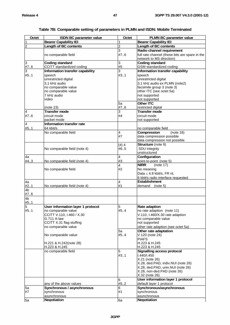
3GPP
3GPP TS 29.007 V4.3.0 (2001-12)47Release 4
Table 7B: Comparable setting of parameters in PLMN and ISDN: Mobile Terminated
Octet ISDN BC parameter value Octet PLMN BC parameter value 1 Bearer Capability IEI 1 Bearer Capability IEI 2 Length of BC contents 2 Length of BC contents
no comparable field 3 #7..6
Radio channel requirement full rate channel (these bits are spare in the network to MS direction)
3 #7..6
Coding standard CCITT standardized coding
3 #5
Coding standard GSM standardized coding
3 #5..1
Information transfer capability speech unrestricted digital 3,1 kHz audio no comparable value no comparable value 7 kHz audio video
3 #3..1
Information transfer capability speech unrestricted digital 3,1 kHz audio ex PLMN (note2) facsimile group 3 (note 3) other ITC (see octet 5a) not supported not supported
(note 23)
5a #7..6
Other ITC restricted digital
4 #7..6
Transfer mode circuit mode packet mode
3 #4
Transfer mode circuit mode not supported
4 #5..1
Information transfer rate 64 kbit/s
no comparable field
No comparable field 4 #7
Compression (note 18) data compression possible data compression not possible
No comparable field (note 4)
(4) 4 #6..5
Structure (note 9) SDU integrity unstructured
4a #4..3
No comparable field (note 4)
4 #3
Configuration point-to-point (note 5)
No comparable field
4 #2
NIRR (note 17) No meaning Data ≤ 4.8 kbit/s, FR nt, 6 kbit/s radio interface requested
4a #2..1
No comparable field (note 4)
4 #1
Establishment demand (note 5)
4b #7..6
4b #5..1
5 #5..1
User information layer 1 protocol no comparable value CCITT V.110, I.460 / X.30 G.711 A-law CCITT X.31 flag stuffing no comparable value
5 #5..4
Rate adaption no rate adaption (note 11) V.110, I.460/X.30 rate adaption no comparable value not supported other rate adaption (see octet 5a)
No comparable value H.221 & H.242(note 28) H.223 & H.245
5a #5..4
Other rate adaptation V.120 (note 24) PIAFS H.223 & H.245 H.223 & H.245
no comparable field 5 #3..1
Signalling access protocol I.440/I.450 X.21 (note 26) X.28, ded.PAD, indiv.NUI (note 26) X.28, ded.PAD, univ.NUI (note 26) X.28, non-ded.PAD (note 26) X.32 (note 26)
any of the above values
6 #5..2
User information layer 1 protocol default layer 1 protocol
5a #7
Synchronous / asynchronous synchronous asynchronous
6 #1
Synchronous/asynchronous synchronous asynchronous
5a Negotiation 6a Negotiation

3GPP
3GPP TS 29.007 V4.3.0 (2001-12)48Release 4
Octet ISDN BC parameter value Octet PLMN BC parameter value #6 not possible
inband neg, possible (note 16) #6 not possible
no comparable value 5a #5..1
User rate 0,3 kbit/s 1,2 kbit/s 2,4 kbit/s 4,8 kbit/s 9,6 kbit/s 12 kbit/s rate is indicated by Ebit as specified in rec. I.460 0,6 kbit/s 3,6 kbit/s 7,2 kbit/s 8 kbit/s 14,4 kbit/s 16 kbit/s 19.2 kbit/s 28.8 kbit/s 32 kbit/s 38.4 kbit/s 48 kbit/s 56 kbit/s 57.6 kbit/s 0,1345 kbit/s 0,1 kbit/s 75 bit/s / 1,2 kbit/s 1,2 kbit/s / 75 bit/s 0,110 kbit/s 0,2 kbit/s
6a #4..1
User rate (note 18 and 29) 0,3 kbit/s 1,2 kbit/s 2,4 kbit/s 4,8 kbit/s 9,6 kbit/s 12 kbit/s (note 13) (note 16) not supported not supported not supported not supported (note 20) not supported (note 20) (note 20) (note 20) (note 20) (note 20) (note 20) not supported not supported not supported not supported not supported not supported not supported
5b #7..6
Intermediate rate not used (note 19) 8 kbit/s 16 kbit/s 32 kbit/s
6b #7..6
Intermediate rate (note 6) (note 18) 8 or 16 kbit/s 8 kbit/s 16 kbit/s
5b #5
NIC on Tx (note 14) does not require requires
6b #5
NIC on Tx does not require requires (note 13)
5b #4
NIC on Rx (note 14) cannot accept can accept
6b #4
NIC on Rx cannot accept can accept (note 13)
5b #3
Flow control on Tx (note 15) Not Required Required
no comparable field
5b #2
Flow control on Rx (note 15) Cannot Accept Accept
no comparable field
5c #7..6
Number of stop bits 1 bit 2 bits not used 1.5 bits
6a #7
Number of stop bits 1 bit 2 bits no comparable value not supported
5c #5..4
Number of data bits 7 bits 8 bits not used 5 bits
6a #5
Number of data bits 7 bits 8 bits no comparable value not supported
5c #3..1
Parity information odd even none forced to 0 forced to 1
6b #3..1
Parity information odd even none forced to 0 forced to 1
no comparable field
6c #7..6
Connection element (note 1) transparent non-transparent (RLP) both, transp. preferred
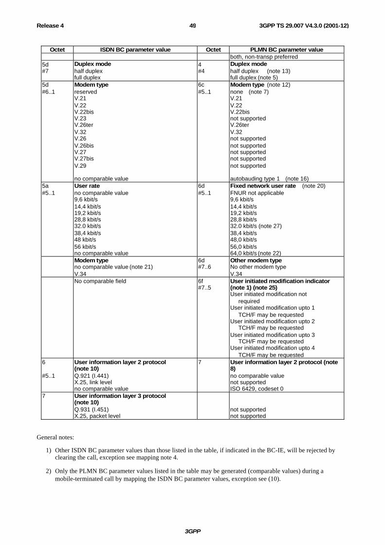
3GPP
3GPP TS 29.007 V4.3.0 (2001-12)49Release 4
Octet ISDN BC parameter value Octet PLMN BC parameter value both, non-transp preferred
5d #7
Duplex mode half duplex full duplex
4 #4
Duplex mode half duplex (note 13) full duplex (note 5)
5d #6..1
Modem type reserved V.21 V.22 V.22bis V.23 V.26ter V.32 V.26 V.26bis V.27 V.27bis V.29 no comparable value
6c #5..1
Modem type (note 12) none (note 7) V.21 V.22 V.22bis not supported V.26ter V.32 not supported not supported not supported not supported not supported autobauding type 1 (note 16)
5a #5..1
User rate no comparable value 9,6 kbit/s 14,4 kbit/s 19,2 kbit/s 28,8 kbit/s 32.0 kbit/s 38,4 kbit/s 48 kbit/s 56 kbit/s no comparable value
6d #5..1
Fixed network user rate (note 20) FNUR not applicable 9,6 kbit/s 14,4 kbit/s 19,2 kbit/s 28,8 kbit/s 32.0 kbit/s (note 27) 38,4 kbit/s 48,0 kbit/s 56,0 kbit/s 64,0 kbit/s (note 22)
Modem type no comparable value (note 21) V.34
6d #7..6
Other modem type No other modem type V.34
No comparable field 6f #7..5
User initiated modification indicator (note 1) (note 25) User initiated modification not required User initiated modification upto 1 TCH/F may be requested User initiated modification upto 2 TCH/F may be requested User initiated modification upto 3 TCH/F may be requested User initiated modification upto 4 TCH/F may be requested
6 #5..1
User information layer 2 protocol (note 10) Q.921 (I.441) X.25, link level no comparable value
7 User information layer 2 protocol (note 8) no comparable value not supported ISO 6429, codeset 0
7 User information layer 3 protocol (note 10) Q.931 (I.451) X.25, packet level
not supported not supported
General notes:
1) Other ISDN BC parameter values than those listed in the table, if indicated in the BC-IE, will be rejected by clearing the call, exception see mapping note 4.
2) Only the PLMN BC parameter values listed in the table may be generated (comparable values) during a mobile-terminated call by mapping the ISDN BC parameter values, exception see (10).

3GPP
3GPP TS 29.007 V4.3.0 (2001-12)50Release 4
3) According to Q.931 (05/98) and 3GPP TS 24.008, respectively, the octets are counted from 1 to n onwards; the bit position in a particular octet is indicated by #x..y, with {x,y} = 1..8 (bit 1 is the least and bit 8 the most significant bit).
4) If octets 5 to 5d of the ISDN BC are absent but present in the LLC, the LLC octets should apply for the mapping as indicated above. In the case of V.120 interworking (see note 24) these LLC octets shall apply.
5) If within the ISDN BC the parameters information transfer capability indicates "3,1 kHz audio" and user layer 1 protocol indicates "G711 A-law" or "G.711 µ-law" (PCS-1900) but no modem type is available and the HLC does not indicate "facsimile group 3", octets 5 to 5d of the LLC, if available, apply for the above mapping procedure.
6) The number of octets which shall be encoded for the PLMN BC-IE must comply to encoding rules in 3GPP TS 24.008 and the combination of the different parameter values shall be in accordance to 3GPP TS 27.001.
Notes regarding particular entries in table 7B:
1) This PLMN parameter value is inserted according to user rate requirements and network capabilities / preferences.
2) This PLMN parameter value is inserted, if the information transfer capability in ISDN BC is "3,1kHz audio" and a comparable modem type is specified.
3) This PLMN parameter value is inserted, if the information transfer capability is "3,1 kHz audio" and the content of the HLC-IE, if any, indicates "facsimile group 2/3", (for details refer to subclause 10.2.2 case 3 for HLR action and case 5 for VMSC action). Note that via MAP the value "alternate speech/facsimile group 3 - starting with speech" shall be used, when TS 61 applies.
4) When interworking with an ISDN according to ETS 300 102-1, octets 4a and 4b may be present. The values are ignored and PLMN values are set according to notes 5 and 9.
5) This PLMN parameter value is inserted if the comparable ISDN parameter value is missing.
6) The value of the Intermediate Rate field of the GSM Bearer Capability information element shall only depend on the value of the user rate in the same information element. If the connection element is "transparent", the value is 16 kbit/s, if the user rate is 9.6 or 12 kbit/s, and 8 kbit/s otherwise. For any other connection element setting the value is 16 kbit/s.
7) This PLMN BC parameter value is inserted, if the PLMN BC parameter "Information Transfer Capability" indicates "Unrestricted digital information", "facsimile group 3" or "alternate speech/facsimile group 3, starting with speech".
8) Where the network indicates "asynchronous" and connection elements "non-transparent", "both, transparent preferred" or "both, non-transparent preferred" , then the GSM BC should be forwarded without parameter user information layer 2 protocol, see also (10).
9) The PLMN parameter value shall be set to "unstructured" where the network indicates connection element "transparent". Where the network indicates connection elements "non transparent" "both, transparent preferred" or "both, non transparent preferred" the value of the parameter structure shall be set to "SDU Integrity".
10) Mapping of parameter values of this octet to PLMN BC parameters and values are subject to specific application rules, i.e. unless otherwise explicitly stated in an appropriate TS mapping to PLMN BC parameters shall not take place.
11) This value shall be used when the value of the PLMN BC parameter "Information Transfer Capability" indicates the value "3,1 kHz audio ex PLMN", "facsimile group 3" or "alternate speech/facsimile group 3, starting with speech" which is reserved for MAP operations.
12) The modem encoding of both Q.931 (05/98) and ETS 300 102-1 version 1 shall be accepted and mapped according to 3GPP TS 24.008.
13) Value not used for currently defined bearer services and Teleservices.
14) NIC is only supported in GSM for "3,1 kHz Ex PLMN audio" interworking with synchronous data transmission.

3GPP
3GPP TS 29.007 V4.3.0 (2001-12)51Release 4
15) Because the required flow control mechanism can not be indicated to the MS (refer to 3GPP TS 27.001), the network shall check if the flow control mechanism selected by the MS and indicated in the CALL CONFIRMED message suits to the requirements requested by the ISDN terminal adaptor. In case of a mismatch the call shall be released in the IWF.
Because an asymmetric flow control mechanism (with respect to transmitting and receiving side) is not supported in the PLMN, the different values of the ISDN BC-IE parameters "flow control on Tx" and "flow control on Rx" shall be interpreted in the following way:
- "Flow control on Rx" set to "accepted" matches with "outband flow control", irrespective of the value of the parameter "flow control on Tx".
- "Flow control on Rx" set to "not accepted" and "flow control on Tx" set to "not required" matches with "inband flow control" and "no flow control".
- where "Flow control on Rx" is set to "not accepted" and "flow control on Tx" to "required" the call shall be released by the IWF.
16) If in case of 3,1 kHz audio interworking "inband negotiation possible" is indicated and the parameter user rate is set to "rate is indicated by E bits specified in Recommendation I.460 or may be negotiated inband" the user rate in the PLMN BC-IE shall be set according to a network preferred value. If ISDN-BC parameter modem type is present, its value shall be ignored. The PLMN-BC parameter modem type shall be set according to the user rate in case of connection element "transparent" and to "autobauding type 1" in case of connection element "non transparent", "both, transparent preferred" or "both, non transparent preferred". In case of data compression high speed modems, like V.32bis, V.34 and/or V.90 may be used in the IWF. Autobauding may also be used to support user rates less than 9.6 kbit/s towards the PSTN.
For unrestricted digital interworking the call shall be rejected if these values are indicated. If the PLMN-BC parameter modem type indicates "autobauding type 1" or "none", then the PLMN-BC parameter other modem type shall be set to "no other modem type".
17) For the use of NIRR see 3GPP TS 27.001. The VMSC shall set this parameter dependent upon its capabilities and preferences.
18) If compression is supported by the MSC, the value "data compression possible" may be set. Depending on the capabilities of the MSC, the user rate value and the intermediate rate value is set to an appropriate value.
19) Only applicable if the parameter ISDN-BC ITC indicates "3,1 kHz audio" and for "UDI" calls if User Rate > "19,2 kbit/s".
20) The user rate of the PLMN BC is set to the value for the fall-back bearer service. In case the mobile station does not support the fixed network user rate (i.e. the call confirmation message does not contain the fixed network user rate parameter), the network may release the call for a transparent connection element.
21) The modem type parameter of the PLMN -BC is taken into account, only.
22) In case no LLC is received and the ISDN-BC received consists of octets 1 to 4 only, coded:
Coding standard: CCITT Information Transfer capability: UDI Transfer mode: circuit Information transfer rate: 64kbit/s
the following PLMN -BC parameters, shall be set to:
fixed network user rate: 64 kbit/s connection element: transparent bothNT or bothT (If IWF supports FTM or PIAFS)
The other parameters of the PLMN -BC shall be set to values indicating a fall-back service.
23) When the MSC is directly connected to a restricted 64 kbit/s network, the ISDN BC-IE is coded with an ITC = RDI. An ISDN BC-IE, as specified in ETR 018 and shown below, shall be taken to indicate that interworking with an indirectly connected restricted 64 kbit/s network is required:

3GPP
3GPP TS 29.007 V4.3.0 (2001-12)52Release 4
Coding standard: CCITT Information Transfer capability: UDI Transfer mode: circuit Information transfer rate: 64 kbit/s User information layer 1 protocol: V.110/X.30 Synchronous/Asynchronous: synchronous Negotiation: In-band negotiation not possible User rate: 56 kbit/s
In this case the PLMN BC parameter Information Transfer Capability is set to „Other ITC" and Other ITC parameter is set to „restricted digital".If ISDN LLC exists, all the corresponding fields in the PLMN BC shall be derived from the ISDN LLC. Otherwise, the corresponding fields in the UMTS BC shall be derived from the ISDN BC. In the above both case, Connection element is set as follows.
Connection element: transparent bothNT or bothT (If IWF supports FTM)
24) V.120 interworking is required if the ISDN LLC parameter User Information Layer 1 Protocol is set to „V.120". In this case the PLMN BC parameter Rate Adaptation is set to „Other rate adaptation" and Other Rate Adaptation parameter is set to „V.120". All the corresponding fields in the GSM BC shall be derived from the ISDN LLC.
25) This parameter is only included in case of non-transparent multislot connections.
26) This value was used by services defined for former GSM releases and does not need to be supported.
27) Following BC parameters in SETUP message shall be set to:
Fixed network user rate 32 kbit/s Connection element transparent (for multimedia)
bothNT or bothT (If IWF supports PIAFS, UMTS only)
28) UIL1P is set to "H.221 & H.242" or "H.223 & H.245" by H.324/I. In the case where UIL1P is set to "H.221 and H.242", this should be mapped to "H.223 & H.245".
29) In UMTS, if the User Rate of the ISDN BC is less than 9,6 kbit/s and the Connection Element is mapped to "NT", then FNUR is fixed to 9,6 kbit/s.
10.2.3 Transparent service support The protocol stacks for transparent services are specified in 3GPP TR 43.010 (GSM) and in 3GPP TR 23.910 (UMTS).
In UMTS, the transparent services are based in the Iu User Plane protocol specified in 3GPP TS 25.415.
In GSM identifies the rate adaptation scheme shall be utilized on the BSS to MSC link as identified in 3GPP TS 48.020. The transcoding function will generate the 64 kbit/s rate adapted format utilizing the 8 and 16 kbit/s intermediate data rates. The MSC - MSC/IWF will utilize the same rate adaptation scheme as that indicated in 3GPP TS 48.020, i.e. adapted to 64 kbit/s.
10.2.3.1 Structure of the MSC/IWF for UMTS
The transmission towards the RNC is based on AAL2. The Iu UP is used in the transparent mode.
ATMAAL2Iu UP
ISDN TAfunction
MODEM CODEC3.1kHzaudio
64 kbit/s unrestrictedor 56 kbit/s restricted
64 kbit/s unrestrictedor 56 kbit/s restricted
Figure 10: Structure of the MSC/IWF (transparent)

3GPP
3GPP TS 29.007 V4.3.0 (2001-12)53Release 4
10.2.3.2 Structure of the MSC/IWF for GSM
When interworking to the unrestricted digital bearer service rate adaptation according to ITU-T V.110 will be necessary within the MSC/IWF. For multislot, TCH/F14.4 or EDGE operations MSC/IWF shall adapt the data stream as defined in 3GPP TS 44.021 and 3GPP TS 48.020.
NOTE: From the perspective of MSC/IWF, a TCH/F28.8 EDGE configuration is identical to a multislot 2×TCH/F14.4 configuration.
When interworking to the 3,1 kHz audio service, then the same process as for the PSTN case is necessary (section 9.2.3.2).
3.1 kHzaudio
MODEM CODEC
ISDN TAfunction
64 kbit/s unrestrictedor 56 kbit/s restricted
RA2
RA1
RA0
RA1status
data
64 kbit/s unrestricted
or 56 kbit/s restricted
Figure 11: Structure of the MSC/IWF (transparent)
10.2.3.3 Mapping of signalling MS/MSC/IWF to modem or ISDN (V.110) TA-function interface requirements
For the 3,1 kHz audio interworking case see subclause 9.2.3.3.
Status bits SA, SB and X can be used to convey channel control information associated with the data bits in the data transfer state. Table 8 shows the mapping scheme between the V.24 circuit numbers corresponding to the V-series DCE functions and the status bits for the transparent mode. It also shows how the unused status bits should be handled. It is derived from the General Mapping scheme described in annex B. A binary 0 corresponds to the ON condition, a binary 1 to the OFF condition.
The transport of these status bits by the various channel codings is described in 3GPP TS 44.021 and 48.020 for GSM. For UMTS refer to 3GPP TR 23.910.
NOTE Although the interface to the ISDN TA function is described in terms of V.24 interchange circuit functions, this does not imply that such circuits need to be physically realised.

3GPP
3GPP TS 29.007 V4.3.0 (2001-12)54Release 4
Table 8: Mapping scheme at the IWF for the transparent mode
Mapping direction: MS to IWF
Mapping direction: IWF to MS
Signal at IWF ISDN TA interface or condition
within the IWF always ON (note 1) CT 105
to status bit X CT 106 not mapped (note 5) CT 107
not mapped (note 6) CT 108 to status bit SB CT 109
always ON (note 2) CT 133 from status bit SA (note 3) ignored by IWF from status bit SB (note 1) ignored by IWF from status bit X (note 4) ignored by IWF
to status bit SA (note 3) always ON NOTE 1: The SB bit towards the IWF, according to the General Mapping (annex B),
could be used to carry CT 105 from the mobile DTE to the ISDN TA function in the IWF. However, CT 105 should always be ON at the DTE interface in the data transfer state since only duplex operation is supported. Also, many DTEs use the connector pin assigned to CT 105 for CT 133. Therefore, CT 105 shall always be set to ON at the IWF ISDN TA function during the data transfer state.
NOTE 2: CT 133 is not mapped since there is no flow control in transparent mode. NOTE 3: The SA bits in both directions are available only with certain channel
codings. Therefore, for maximum compatibility, they should not be mapped.
NOTE 4: The X bit towards the IWF is not mapped since there is no flow control in transparent mode.
NOTE 5: CT 107 is not used by the IWF. NOTE 6: CT 108 is used in the call setup and answering processes.
10.2.3.4 Establishment of end-to-end terminal synchronizations
Prior to exposing the traffic channel of a PLMN connection to transmission of user data, the controlling entities of the connection shall assure of the availability of the traffic channel. This is done by a so called synchronizations process:
- starting on the indication of "physical connection established" resulting from the PLMN-inherent outband signalling procedure This indication is given on sending the message CONNECT in case of MOC, CONNECT ACKNOWLEDGEMENT in case of MTC and MODIFY COMPLETE (which is sent after reception of the ASSIGN COMPLETE message) in case of in-call modification;
- ending by indicating the successful execution of this process to the controlling entity, which then takes care of the further use of the inband information (data, status).
Network interworking within an MSC/IWF is concerned with the terminating side (to the MS / UE) and the transit side (to the fixed network) of a connection. Both sides shall be treated individually related to the synchronizations process.
10.2.3.4.1 Terminating side (towards the MS / UE)
10.2.3.4.1.1 GSM Traffic channel types TCH/F4.8 and TCH/F9.6
With respect to the terminating side the procedure is as follows:
- sending of synchronizations pattern 1/OFF (all data bits "1"/all status bits "OFF") to the MS using the RA1/RA2 rate adaptation function. In multislot transparent operation, the synchronisation pattern sent is 1/OFF with the exception of the bit positions S1, first X, S3, and S4 which contain the substream number and multiframe alignment pattern (Ref. 3GPP TS 44.021);
- searching for detection of the synchronizations pattern from the MS within valid V.110 frames, and in multislot operation, also searching for the multiframe alignment pattern "0000 1001 0110 0111 1100 0110 1110 101" (Ref. to 3GPP TS 44.021) in bit position S4 and substream numbers in bit positions S1, first X, and S3. This implies that the E1, E2 and E3 bit of the V.110 frame shall be checked for the appropriate user rate in order to distinguish the synchronization pattern from the BSS idle data frame.
3GPP
3GPP TS 29.007 V4.3.0 (2001-12)55Release 4
- Timer T (= 500 ms) is started for each of the allocated traffic channel(s) of the call on receipt of the synchronizations pattern from the MS.
- When the frame alignment pattern and, in case of multislot operation, the multiframe alignment pattern have been recognized as a steady state, the MSC/IWF continues sending the synchronizations patterns to the MS until a timer T expires.
10.2.3.4.1.2 GSM Traffic channel type TCH/F14.4
With respect to the terminating side the procedure is as follows:
- Sending A-TRAU frames with the data rate set in the bits C1-C4 (TS 48.020) and data bits set to one, sending the multiframe structure with the alignment pattern (bit M1) and with the status bits OFF (bit M2) and, in a multislot case, sending substream numbers (bit M2).
- Searching for the detection of the multiframe alignment pattern „0000 1001 0110 0111 1100 0110 1110 101" (TS 44.021) in the bit M1 and, in a multislot case, searching for substream numbers in the bit M2. (Any 5 bit sequence in the multiframe alignment pattern is unique, i.e. the multiframe alignment can take place by recognition of five successive M1 bits).
- Timer T (= 500 ms) is started for each of the allocated traffic channel(s) of the call on receipt of the synchronizations pattern from the MS.
- When the frame alignment pattern and the multiframe alignment pattern have been recognized as a steady state, the MSC/IWF continues sending the synchronizations patterns to the MS until a timer T expires.
10.2.3.4.1.3 UMTS User Plane
The procedures are the same as for the modem case, but, depending on implementation, the IWF may through connect before the fixed network leg has been synchronised.
10.2.3.4.2 Transit side (towards the fixed network).
In case of interworking to the ISDN "3,1 kHz audio" bearer service the synchronization process is as for the PSTN interworking case (see subclause 9.2.3.4.2).
In case of V.110 interworking to the ISDN unrestricted digital bearer service the following synchronization process shall be performed.
The interchange circuits towards the V.110 ISDN TA function are held in the OFF condition until timer T expires, when they are switched to ON.
From this time, after the expiration of the timer T of every allocated traffic channel, the information on CT106 and CT109 from the IWF V.110 ISDN TA function are directly mapped to the X and SB bits, respectively, towards the MS. For TCH/F14.4 the X and SB bits are mapped to the M2 multiframe bits according to 3GPP TS 44.021. Circuit 108 to the selected V.110 ISDN TA function associated with the connection will be switched from the "OFF" to "ON" condition, thus initiating the synchronization process on the fixed network according to ITU-T V.110. The IWF is allowed to map CT 104 to the data bits sent towards the MS and to map data bits received from the MS to CT 103.
10.2.3.5 Network independent Clocking (NIC)
Due to the incompatibility between the ISDN and the GSM requirements for NIC interworking is not provided between these two formats. As such no NIC function is required in providing interworking to the ISDN. In this case, the IWF shall disregard the value of bits E4, E5, E6 and E7 in the data transmission phase.
10.2.4 Non-transparent service support The protocol stacks for non-transparent services are specified in 3GPP TR 43.010 (GSM) and in 3GPP TR 23.910 (UMTS). Both of the systems use the Radio Link Protocol (RLP) specified in 3GPP TS 24.022.
In UMTS, the non-transparent services are based in the Iu User Plane protocol specified in 3GPP TS 25.415.

3GPP
3GPP TS 29.007 V4.3.0 (2001-12)56Release 4
In GSM the corresponding necessary support concerning the rate adaptation scheme shall be utilized on the BSS-MSC link as identified in 3GPP TS 48.020.
For the non-transparent service support the MSC/IWF will select the modem and speed based on the Compatibility information contained in either the call set-up or call confirmed message, reference subclauses 9.2.1 and 9.2.2. Where the Modem Type indicated is autobauding type 1, the MSC/IWF may select any speed and modem type according to what it can negotiate with the remote modem. In this case User Rate and Fixed Network User Rate, if present, has no meaning.
10.2.4.1 Structure of the MSC/IWF for UMTS
The transmission towards the RNC is based on AAL2. The Iu UP is used in the support mode. The RLP/L2R extends to the MS.
L2R
RLP 3.1 kHzaudio
MODEM CODEC
ISDN TAfunction
64 kbit/s unrestrictedor 56 kbit/s restricted1)
AAL2
Iu UP Dataandstatus
ATM
1) not applicable for PIAFS
Figure 12: Structure of the MSC/IWF (non-transparent)
10.2.4.2 Structure of the MSC/IWF for GSM
The rate adaptation process will be the same as for the transparent case. , except that a TCH/F43.2 channel coding is also supported. From MSC/IWF's perspective a TCH/F43.2 EDGE configuration is identical to a multislot 3×TCH/F14.4 configuration.
3GPP TR 43.010 identifies the protocol layer structure for the non-transparent case, the MSC/IWF provides the inverse of the action in the MS terminal adaptation function. For a multislot configuration refer to 3GPP TR 43.010.
The V.110, V.120 and PIAFS ISDN TA (terminal adapter) functions provide the same functionality and operational behaviour as fixed ISDN terminal adapters that conform to the corresponding ITU-T Recommendations (V.110 or V.120).
L2R
RLP 3.1 kHzaudio
MODEM CODEC
ISDN TAfunction
64 kbit/s unrestrictedor restricted
RA2
RA1
Dataandstatus
Figure 13: Structure of the MSC/IWF (non-transparent)

3GPP
3GPP TS 29.007 V4.3.0 (2001-12)57Release 4
10.2.4.3 Re-constitution of user data
3GPP TS 24.022 refers to the frame of user data in the radio link protocol. The layer 2 relay functions in the MS and the MSC/IWF (identified in 3GPP TS 43.010 and 3GPP TS 23.910) contain the mechanism for packing and unpacking the user data into the L2R protocol data units.
10.2.4.4 Layer 2 relay functionality
Specific functionality is required on the L2R dependant upon the service which is being requested to be supported. The selection of the appropriate L2R function will be determined by the MSC/IWF on the basis of the bearer capability information signalled in the call set-up request, or call confirmation message. The prime information element being transparent or non transparent service indication. In addition the particular L2R function - type of protocol to be terminated and mode of flow control to be applied (see appropriate subclauses in 3GPP TS 27 series) - will be selected on the basis of the user's layer 2 indication.
The specific interaction between the L2R function and the RLP function and the L2R frame structure will be the same as that detailed in the Annex to the appropriate 3GPP TS 27 series.
10.2.4.5 In band signalling mapping flow control
This entails the L2R function providing the means of controlling and responding to flow control function of the modem (or in the rate adapted frame) plus any synchronizations requirements related to flow control. For for asynchronous services a specific rule applies for flow control (see 3GPP TS 27.001).
In case of interworking to the ISDN "3,1kHz audio" bearer service the flow control process is as for the PSTN interworking case (see subclause 9.2.4.5). In case of interworking to the ISDN unrestricted digital bearer service the following procedures apply:
The flow control function chosen will be dependent upon the availability of the "user information layer 2" information element of the PLMN BC and if available its value.
For V.110 interworking, outband flow control will be by means of the "X" bit in the V.110 frame to the ISDN.
For V.120 interworking, outband flow control shall be as follows. In Multiple frame acknowledged mode the functions of the data link control sublayer (send RNR or withhold update of the sequence state variable V(R)) shall be used. In Unacknowledged mode the RR bit in the Control State octet shall be used.
For PIAFS interworking, outband flow control shall be as follows. The functions of the data link control sublayer (withhold update of the frame number) shall be used.
If flow control is provided irrespective of the type used, the L2R function shall:
a) provide immediate indication of flow control to the fixed network on receipt of flow control request from the MS; and/or
b) provide immediate indication of flow control to the MS on receipt of flow control request from the fixed network i.e. in the next available L2R status octet to be transmitted.
Where in band (X-on/X-off) flow control is in use, then the X-on/X-off characters will not be passed across the radio interface.
If no flow control is provided the involved end systems are responsible for performing in-band flow control on their own by taking into account the buffer capacity of the MSC/IWF as stated below.
10.2.4.5.1 Conditions requiring flow control - if flow control is provided - towards the fixed network
The L2R function will initiate flow control in the following circumstances:
1) the transmit buffer to the radio side reaches a preset threshold (BACK PRESSURE);
2) the L2R function receives a "flow control active" indication.
On removal of buffer congestion or receipt of L2R "flow control inactive" the flow control will be removed.
3GPP
3GPP TS 29.007 V4.3.0 (2001-12)58Release 4
No flow initiation/removal will take place at the L2R function and loss of data may occur, if no flow control is provided.
10.2.4.5.2 Conditions requiring flow control towards the MS
The L2R function will transmit to the MS a "flow control active indication", if flow control is provided, in the following circumstances:
1) if the receive buffer from the radio side reaches a preset threshold (BACK PRESSURE);
2) if a flow control indication is received from the fixed network customer. On receipt of this flow control indication, transmission of data from the receive buffers towards the fixed network terminal is halted.
On removal of the buffer congestion or fixed network flow control indication, the L2R function will send a "flow control inactive" indication towards the MS. In addition, for the fixed network indication, transmission of data from the receive buffers will be restarted.
If no flow control is provided at the L2R function, no flow control initiation/removal will take place by the MSC/IWF. Data might be lost without any indication by the MSC/IWF to the end systems involved.
10.2.4.6 Data buffers
10.2.4.6.1 Transmit buffers (towards MS)
Incoming data from the fixed network customer shall be buffered such that if the MSC/IWF is unable to transfer data over the radio path the data is not lost.
The buffer shall be capable of holding the data. Its size is up to the implementers. When the buffer is half full flow control towards the fixed network shall be initiated if flow control is provided as per subclause 10.2.4.5.1.
10.2.4.6.2 Receive buffers (from MS)
Incoming data from the MS is buffered such that if the fixed network terminal is unable to accept the data then it is not lost.
The buffer shall be capable of holding the data. Its size is up to the implementers. When the buffer becomes half full, the L2R function will send a "flow control active" indication towards the MS if flow control is provided at the L2R function, as per subclause 10.2.4.5.2.
10.2.4.7 BREAK Indication
The BREAK indication is managed as detailed in subclause 9.2.4.7.
When V.120 rate adaptation is being used in protocol sensitive asynchronous mode on the ISDN, the L2R break condition shall map on to the BR bit of the V.120 header octet.
10.2.4.8 Signalling mapping of modem or ISDN (V.110, V.120 or PIAFS) TA-function status information
Status information is carried between the modem or ISDN (V.110, V.120or PIAFS) TA-function in the IWF and the terminal adaption function in the MS by the L2R function. The L2RCOP entity transfers interface status information between L2Rs via the status octets SA, SB and X in L2RCOP-PDUs (3GPP TS 27.002). Table 9 shows the mapping scheme between the V.24 circuit numbers corresponding to the V-series DCE functions and the status bits for the non-transparent mode. It also shows how the unused status bits should be handled. It is derived from the General Mapping scheme described in annex B. A binary 0 corresponds to the ON condition, a binary 1 to the OFF condition.
NOTE. Although the interface to the ISDN TA function is described in terms of V.24 interchange circuit functions, this does not imply that such circuits need to be physically realised.

3GPP
3GPP TS 29.007 V4.3.0 (2001-12)59Release 4
Table 9: Mapping scheme at the IWF for the non-transparent mode
Mapping direction: MS to IWF
Mapping direction: IWF to MS
Signal at IWF ISDN TA interface or condition within
the IWF always ON (note 1) CT 105
to status bit X (notes 4, 7) CT 106 (note 7) not mapped (note 5) CT 107
not mapped (note 6) CT 108 to status bit SB CT 109
from status bit X (note 8) CT 133 (notes 3, 8) from status bit SA (note 2) ignored by IWF from status bit SB (note 1) ignored by IWF
to status bit SA (note 2) always ON NOTE 1: The SB bit towards the IWF, according to the General Mapping (annex B), could be
used to carry CT 105 from the mobile DTE to the ISDN TA function in the IWF. However, CT 105 should always be ON at the mobile DTE interface in the data transfer state since only duplex operation is supported. Also, many DTEs use the connector pin assigned to CT 105 for CT 133. Therefore, CT 105 shall always be set to ON at the ISDN TA function during the data transfer state.
NOTE 2: The SA bits (both directions) are not mapped since CTs 107 and 108 are handled locally (notes 5, 6).
NOTE 3: The condition of CT 133 (or other flow control mechanism) may also be affected by the state of the L2R transmit buffer (towards the MS) in the IWF and the state of RLP (RR/RNR).
NOTE 4: The condition of status bit X towards the MS may also be affected by the state of the L2R receive buffer in the IWF (from the MS).
NOTE 5: CT 107 is not used by the IWF. NOTE 6: CT 108 is used in the call setup and answering processes. NOTE 7: For inband flow control, CT 106 is not mapped and the status bit X towards the MS
is controlled by the reception of XON and XOFF characters from the ISDN TA function.
NOTE 8: For inband flow control, changes in the condition of the status bit X from the MS result in the sending of XON or XOFF to the ISDN TA function. CT 133 is always set to ON.
10.2.4.9 Support of out-band flow control
Out-band flow control in the case of V.110 rate adaption requires V.110 TA to TA "end-to-end flow control" as defined therein. If this functionality is requested by MS but cannot be supported by the MSC/IWF for any reason (refer also to note 15 of table 7B) the call pending shall be released.
For V.120 interworking, outband flow control shall be as follows. In Multiple frame acknowledged mode the functions of the data link control sublayer (send RNR or withhold update of the sequence state variable V(R)) shall be used. In Unacknowledged mode the RR bit in the Control State octet shall be used.
10.2.4.10 Synchronizations
In case of interworking to the ISDN "3,1kHz audio" bearer service the synchronization process is as for the PSTN interworking case (see subclause 9.2.3.4). In case of interworking to the ISDN unrestricted digital bearer service the following synchronization process shall be performed:
10.2.4.10.1 V.110 and V.120 Frame synchronizations
The ISDN frame synchronizations will need to be mapped to the frame synchronizations utilized on the MSC/IWF to MSC link.
10.2.4.10.2 RLP Frame start indication
The frame start indication is defined in 3GPP TS 48.020. Link establishment and frame error recovery are defined in 3GPP TS 24.022.

3GPP
3GPP TS 29.007 V4.3.0 (2001-12)60Release 4
10.2.4.10.3 L2R Frame synchronizations
The synchronizations of user data and its interaction between the L2R function and RLP function are defined in 3GPP TS 27 series.
10.2.4.10.4 Establishment of end-to-end terminal synchronizations
Prior to exposing the traffic channel of a PLMN connection to transmission of user data, the controlling entities of the connection shall assure of the availability of the traffic channel. This is done by a so called synchronization process:
- starting on the indication of "physical connection established" resulting from the PLMN-inherent outband signalling procedure This indication is given on sending the message CONNECT in case of MOC, CONNECT ACKNOWLEDGEMENT in case of MTC and MODIFY COMPLETE (which is sent after reception of the ASSIGN COMPLETE message) in case of in-call modification;
- ending by indicating the successful execution of this process to the controlling entity, which then takes care of the further use of the in-band information (data, status).
Network interworking within an MSC/IWF is concerned with the terminating side (to the MS) and the transit side (to the fixed network) of a connection. Both sides shall be treated individually related to the synchronization process.
10.2.4.10.4.1 Terminating side (towards the MS)
The procedures are the same as for the modem case.
10.2.4.10.4.2 Transit side (towards the fixed network)
Depending upon implementation, the synchronization of the V.110 or V.120 rate adaptation protocol on the ISDN transit network may be performed either after RLP establishment or in parallel to the RLP establishment. In case of the parallel establishment, data received from the transit side during RLP establishment shall be stored within the L2R buffers until the RLP establishment at the terminating side has been finished. When the RLP has been established and on recognizing frame alignment the information from/to the RLP is mapped by the L2R entity applicable to this particular bearer capability.
For V.110 rate adaptation on the ISDN, the synchronization process consists of sending the V.110 frame structure and looking for incoming frame synchronization according to the procedures in ITU-T V.110.
For V.120 rate adaptation the following applies. In Multiple frame acknowledged mode, data (I frames) may be sent following an exchange of SABME and UA in the traffic channel. In Unacknowledged mode, data (UI frames) may be sent immediately after an ISUP CONNECT or CONNECT COMPLETE message has been received on the ISDN signalling channel. Optionally, an XID exchange may take place in the traffic channel to verify link integrity.
Note. V.120 allows UI frames to be sent in Multiple frame acknowledged mode at any time in addition to I frames. Whilst the IWF shall not follow this procedure when sending frames, such a sequence of I and UI frames may be received by the IWF. Although not specified in V.120, it is recommended that the IWF should deliver to the MS, the contents of the sequence of I and UI frames in the order in which they are received.
For PIAFS rate adaptation the following applies. Data frame is sent following an exchange of initial negotiation and control frame in the traffic channel.
10.2.4.11 Data compression
When data compression is invoked within a non-transparent bearer service, interworking to the ISDN is realized by mapping the PLMN user rate to at least the same user rate in the ISDN. When the ISDN user rate is the same flow control will ensure data integrity, but the overall performance will be slow. When the ISDN user rate is higher the overall performance may be faster.
10.2.4.12 Additional aspects of V.120 Interworking
V.120 rate adaptation may be invoked with asynchronous services only. V.120 is applicable to both UDI and RDI connections.

3GPP
3GPP TS 29.007 V4.3.0 (2001-12)61Release 4
10.2.4.12.1 V.120 Signalling parameters
The signalling parameters relevant to V.120 will be carried in the ISDN LLC and PLMN BC and PLMN LLC information elements. The mapping of the parameter values takes place in the MSC/IWF.
For mobile terminated calls both single-numbering and multi-numbering scenarios may apply, as defined in subclause 9.2.2. The HLR shall not store an ISDN LLC with the MSISDN.
10.2.4.12.2 V.120 Protocol parameters
The following restrictions apply for the parameters relevant for V.120:
- BS 20 NT will use the protocol sensitive asynchronous mode. As a consequence, the rate adaption header shall always be present.
- Only the default logical link will be established, i.e. the LLI negotiation value is "Default, LLI=256 only".
- V.120 recommends the use of the multiple frame acknowledged information transfer procedure for the protocol sensitive mode of operation.
- The IWF shall use the default value for the V.120 window size and the default value for the maximum transmit information field size. It shall be able to receive frames with the default maximum size.
NOTE: V.120 does not specify the values for these and other HDLC-related parameters directly. They are specified in Q.922 (1992) section 5.9. The information field includes the V.120 terminal adaption data field, the rate adaption header and the header extension (Control State octet), if present.
10.2.4.12.3 Data compression on the ISDN
Whilst V.110 rate adaptation does not support standardized data compression, V.42bis data compression may be used with V.120 protocol sensitive asynchronous mode. This is described in V.120 (10/96) annex C.
10.2.4.12.4 Use of the V.120 Control State (header extension) octet
The bits in the V.120 Control State octet are not used for the control of V.24 interface circuits. In unacknowledged mode the RR bit in the Control State octet is used to carry flow control information between the peer terminal adaption protocol entities. In acknowledged mode the Control State octet is not required.
10.2.4.13 Interworking with restricted 64 kbit/s networks
10.2.4.13.1 Rate adaptation
Both V.110 and V.120 rate adaption protocols may be used on a restricted 64 kbit/s network.
For V.110 rate adaption, the procedure is described in ITU-T Rec. I.464. The RA2 function shall set the 8th bit of each octet in the 64 kbit/s stream to binary 1. A consequence of this is that the highest permitted intermediate rate is 32 kbit/s. At the receiver, the 8th bit shall be ignored.
Rec. V.120 states that the user data shall be rate adapted to 56 kbit/s by using only the first 7 bits of each octet in the 64 kbit/s stream. The 8th bit shall be set to binary 1. At the receiver, the 8th bit shall be ignored.
10.2.4.13.2 MSC - ISDN signalling
When interworking indirectly with restricted 64 kbit/s networks the ISDN BC information element shall be coded according to ETR 018 (as shown in the notes to tables 7A and 7B). The information corresponding to the GSM BC-IE shall be communicated in the ISDN LLC-IE which shall be provided by the MS for mobile originated calls.
In the case of direct interworking, an ITC = RDI in the GSM BC-IE maps on to an ITC = RDI in the ISDN BC-IE for both MO and MT calls.
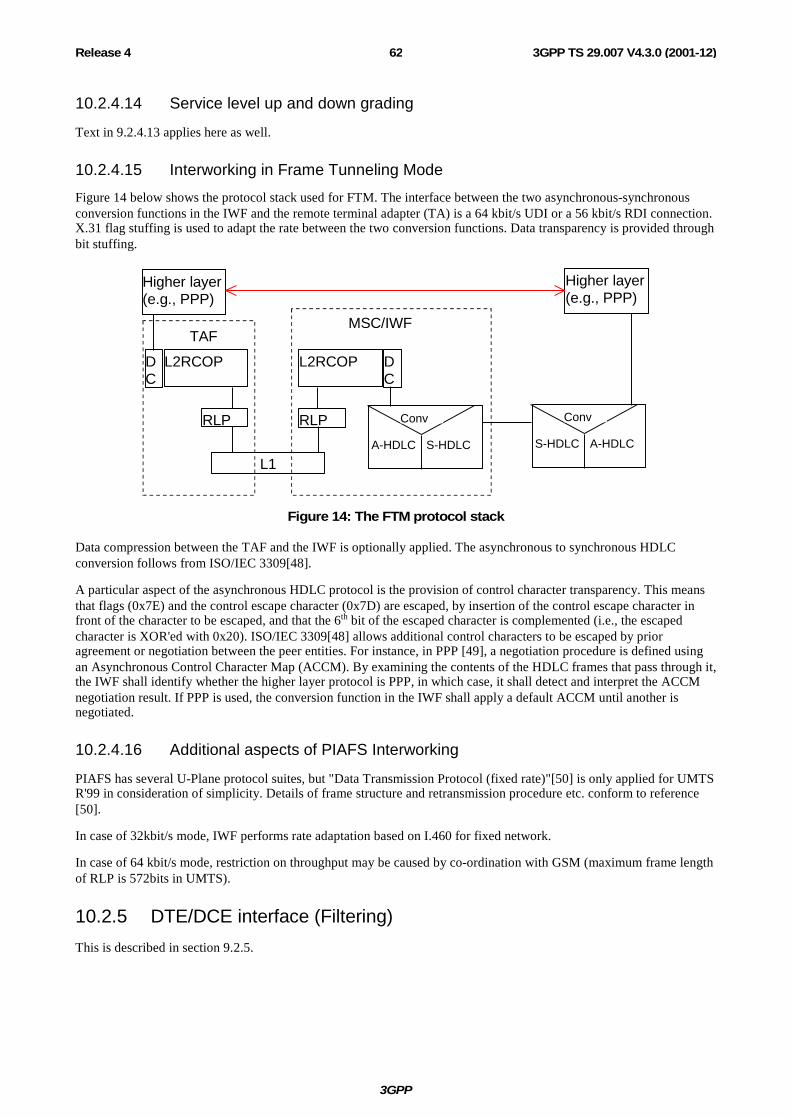
3GPP
3GPP TS 29.007 V4.3.0 (2001-12)62Release 4
10.2.4.14 Service level up and down grading
Text in 9.2.4.13 applies here as well.
10.2.4.15 Interworking in Frame Tunneling Mode
Figure 14 below shows the protocol stack used for FTM. The interface between the two asynchronous-synchronous conversion functions in the IWF and the remote terminal adapter (TA) is a 64 kbit/s UDI or a 56 kbit/s RDI connection. X.31 flag stuffing is used to adapt the rate between the two conversion functions. Data transparency is provided through bit stuffing.
Higher layer(e.g., PPP)
Higher layer(e.g., PPP)
L2RCOPDC
L1
RLP RLP
L2RCOP DC
Conv
A-HDLC S-HDLC
Conv
S-HDLC A-HDLC
MSC/IWFTAF
Figure 14: The FTM protocol stack
Data compression between the TAF and the IWF is optionally applied. The asynchronous to synchronous HDLC conversion follows from ISO/IEC 3309[48].
A particular aspect of the asynchronous HDLC protocol is the provision of control character transparency. This means that flags (0x7E) and the control escape character (0x7D) are escaped, by insertion of the control escape character in front of the character to be escaped, and that the 6th bit of the escaped character is complemented (i.e., the escaped character is XOR'ed with 0x20). ISO/IEC 3309[48] allows additional control characters to be escaped by prior agreement or negotiation between the peer entities. For instance, in PPP [49], a negotiation procedure is defined using an Asynchronous Control Character Map (ACCM). By examining the contents of the HDLC frames that pass through it, the IWF shall identify whether the higher layer protocol is PPP, in which case, it shall detect and interpret the ACCM negotiation result. If PPP is used, the conversion function in the IWF shall apply a default ACCM until another is negotiated.
10.2.4.16 Additional aspects of PIAFS Interworking
PIAFS has several U-Plane protocol suites, but "Data Transmission Protocol (fixed rate)"[50] is only applied for UMTS R'99 in consideration of simplicity. Details of frame structure and retransmission procedure etc. conform to reference [50].
In case of 32kbit/s mode, IWF performs rate adaptation based on I.460 for fixed network.
In case of 64 kbit/s mode, restriction on throughput may be caused by co-ordination with GSM (maximum frame length of RLP is 572bits in UMTS).
10.2.5 DTE/DCE interface (Filtering)
This is described in section 9.2.5.

3GPP
3GPP TS 29.007 V4.3.0 (2001-12)63Release 4
10.3 Interworking Alternate speech facsimile group 3 calls
10.3.1 Alternate speech data bearer interworking
10.3.1.1 General
The procedure for the alternate speech/facsimile group 3 service is invoked at the MS-MSC link during the call set-up phase. This service is invoked by indication of repeated bearer capability information elements in the setup message and/or call confirmed message, respectively (preceded by a repeat indicator "circular"), one indicating speech and the other indicating "facsimile group 3" plus user rate etc., as for normal single calls. The bearer capability first indicated i.e. speech or facsimile determines the first selection required of the network by the subscriber. Depending on the type of service requested and direction of call establishment (M0/MT, see relevant clauses of the 3GPP TS 27 series) low layer and high layer capabilities may also be included. The MSC/IWF will perform both compatibility checking and subscription checking for mobile originated calls and optionally for mobile terminated calls (single numbering scheme) on both sets of capabilities as for normal data calls. If either the subscription check or the compatibility check fails then the call shall be rejected. The only exception to this is when TS61/TS62 negotiation takes place, see 3GPP TS 27.001.
As regards the supplementary services the application rules are laid down in 3GPP TS 22.004.
The speech phase of the call, when invoked, is handled by the transcoder and will utilize the normal telephony teleservice interworking requirements and mobile network capabilities. The Facsimile group 3 phase of the call, when invoked, shall utilize the appropriate data interworking capability (e.g. IWF) and shall use the transparent mobile network capability in GSM or the non-transparent mobile network capability in UMTS.
The network shall provide, for service and operational reasons, a rapid and reliable changeover of capability upon request from the mobile user. This changeover may involve the disabling, by-passing or introduction of particular network functions (e.g. speech coder, modem etc.) and change of the channel configuration on the radio interface. This changeover is initiated on the receipt of the "MODIFY" message (see 3GPP TS 24.008) from the MS. The network itself will not initiate a changeover.
10.3.1.2 Mobile originated ISDN terminated
If one bearer capability information element indicates the ITC value "facsimile group 3", the call set up is as for the PSTN case. Interworking is provided to the ISDN bearer service 3,1 kHz audio for the whole connection, including the speech phase. The MODIFY message (see 3GPP TS 24.008) will be generated by the mobile subscriber. This message is not transmitted to the ISDN, i.e. no outband correlation between the user on the fixed network and the mobile user will be possible. In this instance it is necessary for change of network capabilities to be carried out in the mobile network.
10.3.1.3 ISDN originated mobile terminated
In principle this is handled as for normal ISDN originated call.
When the calling user however indicates an ISDN BC-IE with an ITC value "3,1 kHz audio" and a HLC "facsimile group 3", i.e. the call arrives at the PLMN with compatibility information allowing for deducing the Teleservice "Facsimile transmission", the call setup is as described in subclause 10.2.2 (case 3 in HLR, case 5 in VMSC).
In the information transfer phase the call is dealt with as indicated in the previous paragraph.
10.4 3G-H.324/M calls over UDI/RDI 3G-H.324/M calls provide UDI/RDI(e.g. 32 kbit/s transparent data, 56 kbit/s transparent data or 64 kbit/s transparent data). H.223 and H.245 flow is not terminated in the MSC.
3G-H.324 calls over 64 kbit/s transparent data and 56kbit/s transparent data can be connected to H.324/I calls over UDI/RDI. H.223 protocol is transparent to IWF.
In case of 3G-H.324M calls over 32 kbit/s, IWF which performs rate adaptation between 64kbit/s and 32kbit/s is used. Rate adaptation is based on ITU-T I.460.
3GPP
3GPP TS 29.007 V4.3.0 (2001-12)64Release 4
The support of IWF which transcodes the multiplexes and the content of control, audio, video and data in MSC is FFS.
11 Interworking between GSM and UMTS
11.1 Handover from UMTS to GSM After a handover from UMTS to GSM the user plane between the anchor MSC and the visited MSC shall comply to the standard GSM A-interface protocols, i.e:
- A-TRAU or modified V.110 frames as defined in 3GPP TS 44.021 [27] and 3GPP TS 48.020 [28];
- up to four 16kbit/s substreams are multiplexed in one 64kbit/s channel (Split/Combine function and Multiplexing function as defined in 3GPP TS 44.021 [27] and 3GPP TS 48.020 [28]).
11.2 Handover from GSM to UMTS After a handover from GSM to UMTS the user plane between the anchor MSC and the visited MSC shall comply to the A-TRAU' protocol except for FNUR = 56 kbit/s (ITC=RDI) and FNUR = 64 kbit/s (ITC=UDI). For both exceptions a plain 64 kbit/s channel is used between the MSCs.
The A-TRAU' protocol is defined as follows:
- A-TRAU' frames are transmitted in regular intervals of 10ms;
- an A-TRAU' frame consists of two consecutive A-TRAU frames (as defined in 3GPP TS 48.020 [28]) each with a length of 320 bit;
- the A-TRAU' protocol is used on a plain 64 kbit/s channel without substreams;
- the same A-TRAU' format is used for the transparent and non-transparent transmission mode;
- in transparent mode the number of data bits in an A-TRAU' frame depend on the user rate only, each user rate corresponds to a fixed number of data bits (see below);
- in non-transparent mode A-TRAU' frames contain always complete RLP frames, rate adaptation is performed by means of the M2 bit;
- the M1-bit is used to identify 1st and 2nd frame in both transmission modes.
11.2.1 Frame layout for the different transparent user rates The number of data bits in an A-TRAU' frame depend on the user rate only, each user rate corresponds to a fixed number of data bits in an A-TRAU' frame.
Table 10: A-TRAU' frame layout for transparent user rate
Date Rate Number of data bits per A-TRAU' frame 33.6 kbit/s 336 28.8 kbit/s 288
The data bits are inserted in the A-TRAU' frame starting with D1 of Data field 1 of the first A-TRAU frame. The unused bits are filled with binary '1'.
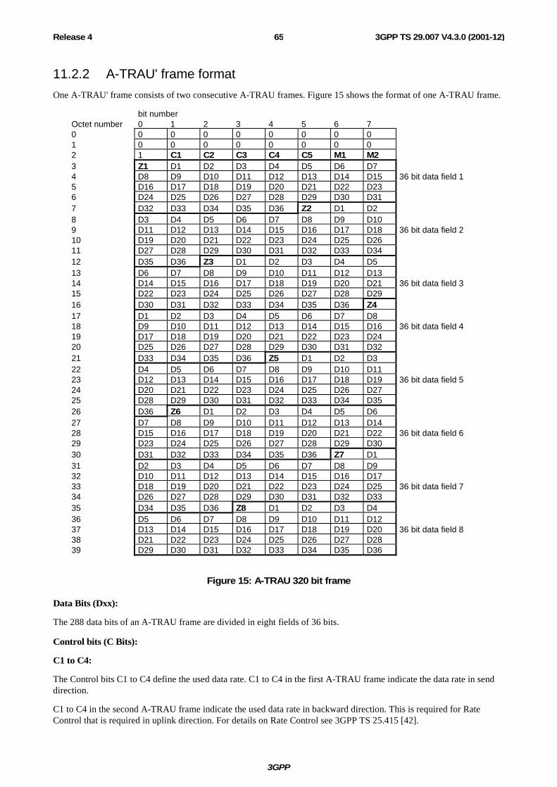
3GPP
3GPP TS 29.007 V4.3.0 (2001-12)65Release 4
11.2.2 A-TRAU' frame format One A-TRAU' frame consists of two consecutive A-TRAU frames. Figure 15 shows the format of one A-TRAU frame.
bit number Octet number 0 1 2 3 4 5 6 7 0 0 0 0 0 0 0 0 0 1 0 0 0 0 0 0 0 0 2 1 C1 C2 C3 C4 C5 M1 M2 3 Z1 D1 D2 D3 D4 D5 D6 D7 4 D8 D9 D10 D11 D12 D13 D14 D15 36 bit data field 1 5 D16 D17 D18 D19 D20 D21 D22 D23 6 D24 D25 D26 D27 D28 D29 D30 D31 7 D32 D33 D34 D35 D36 Z2 D1 D2 8 D3 D4 D5 D6 D7 D8 D9 D10 9 D11 D12 D13 D14 D15 D16 D17 D18 36 bit data field 2 10 D19 D20 D21 D22 D23 D24 D25 D26 11 D27 D28 D29 D30 D31 D32 D33 D34 12 D35 D36 Z3 D1 D2 D3 D4 D5 13 D6 D7 D8 D9 D10 D11 D12 D13 14 D14 D15 D16 D17 D18 D19 D20 D21 36 bit data field 3 15 D22 D23 D24 D25 D26 D27 D28 D29 16 D30 D31 D32 D33 D34 D35 D36 Z4 17 D1 D2 D3 D4 D5 D6 D7 D8 18 D9 D10 D11 D12 D13 D14 D15 D16 36 bit data field 4 19 D17 D18 D19 D20 D21 D22 D23 D24 20 D25 D26 D27 D28 D29 D30 D31 D32 21 D33 D34 D35 D36 Z5 D1 D2 D3 22 D4 D5 D6 D7 D8 D9 D10 D11 23 D12 D13 D14 D15 D16 D17 D18 D19 36 bit data field 5 24 D20 D21 D22 D23 D24 D25 D26 D27 25 D28 D29 D30 D31 D32 D33 D34 D35 26 D36 Z6 D1 D2 D3 D4 D5 D6 27 D7 D8 D9 D10 D11 D12 D13 D14 28 D15 D16 D17 D18 D19 D20 D21 D22 36 bit data field 6 29 D23 D24 D25 D26 D27 D28 D29 D30 30 D31 D32 D33 D34 D35 D36 Z7 D1 31 D2 D3 D4 D5 D6 D7 D8 D9 32 D10 D11 D12 D13 D14 D15 D16 D17 33 D18 D19 D20 D21 D22 D23 D24 D25 36 bit data field 7 34 D26 D27 D28 D29 D30 D31 D32 D33 35 D34 D35 D36 Z8 D1 D2 D3 D4 36 D5 D6 D7 D8 D9 D10 D11 D12 37 D13 D14 D15 D16 D17 D18 D19 D20 36 bit data field 8 38 D21 D22 D23 D24 D25 D26 D27 D28 39 D29 D30 D31 D32 D33 D34 D35 D36
Figure 15: A-TRAU 320 bit frame
Data Bits (Dxx):
The 288 data bits of an A-TRAU frame are divided in eight fields of 36 bits.
Control bits (C Bits):
C1 to C4:
The Control bits C1 to C4 define the used data rate. C1 to C4 in the first A-TRAU frame indicate the data rate in send direction.
C1 to C4 in the second A-TRAU frame indicate the used data rate in backward direction. This is required for Rate Control that is required in uplink direction. For details on Rate Control see 3GPP TS 25.415 [42].
3GPP
3GPP TS 29.007 V4.3.0 (2001-12)66Release 4
Table 11: A-TRAU' control bits
C1 C2 C3 C4 Radio Interface User Rate 1 0 1 1 57,6 kbit/s 1 0 1 0 33,6 kbit/s 1 0 0 0 28,8 kbit/s 0 1 1 1 14,4 kbit/s
C5:
C5 is not used, it is set to binary '1'.
Bit M1:
An A-TRAU' frame is made of two consecutive A-TRAU which build the transport container for 576 data bits. Bit M1 is used to determine the order of the A-TRAU frames within an A-TRAU' frame.
The two M1 bits are referred to as the Frame Start Identifier. The FSI value is 01. These values are assigned to the M1 bit as shown below:
Table 12: Frame Start Identifier
M1 bit First A-TRAU frame 0
Second A-TRAU frame 1
Bit M2:
The M2 bit is used to indicate 'valid' A-TRAU' frames. The M2 bit in both of the two consecutive A-TRAU frames relating to an A-TRAU' frame shall have the same value.
Transparent mode:
In transparent mode M2 is clamped to binary '0'.
Non-transparent mode:
In non-transparent mode M2 is used for DTX. If DTX is applied, M2 is set to binary '1'. If DTX is not to be applied, M2 bit is set to binary '0'. The DTX handling is used in both directions for rate adaptation purpose. This means that the sending entity will insert 'fill RLP-frames' with DTX set to binary '1' in case no RLP-frame is available.
Fill frames are also sent in order to adapt the RLP transmission frequency to the AIUR. The ratio between RLP frames and ‘fill’ RLP frames is defined in the following table:
Table 13: RLP transmission frequency
AIUR Ratio between RLP and ‘fill’ RLP frames
57.6 kbit/s Only valid frames
28.8 kbit/s 1 valid frame followed by 1 ‘fill’ frame
14.4 kbit/s 1 valid frame followed by 3 ‘fill’ frames
Z bits:
The bits Zi are used for Framing Pattern Substitution mechanism. This mechanism is defined in 3GPP TS 48.020 [28].
Mapping of A-TRAU’ frames to PCM time slots:
A-TRAU’ frames shall be mapped octet aligned to PCM time slots. I.e. bit number 0 to 7 of each octet of an A-TRAU’ frame shall be mapped to bit number 0 to 7 of the PCM time slot.

3GPP
3GPP TS 29.007 V4.3.0 (2001-12)67Release 4
11.3 Handover within 3G PLMNs After a handover from a 3G MSC to another 3G MSC the user plane between the anchor MSC or MGW and the visited MSC or MGW shall comply to:
- the Iu UP protocol if both MSC are connected via an ATM interface;
- the A-TRAU' protocol if both MSCs are connected via a TDM interface except for the transparent case FNUR = 32 kbit/s (ITC = UDI or RDI), FNUR = 56 kbit/s (ITC=RDI) and FNUR = 64 kbit/s (ITC=UDI). For these exceptions a plain 64 kbit/s channel is used between the MSCs. The rate adaptation between 64 kbit/s and 32 kbit/s is based on ITU-T I.460 [2].
- the Nb UP protocol if both MGWs are connected via an ATM interface or IP interface
11.4 Handover for 56kbit/s The FNUR = 56 kbit/s in transparent mode can be supported in GSM by two configurations:
1. without IWF with the following channel codings
- 2*TCH/F32.0
- 5*TCH/F9.6
2. with IWF with the following channel coding
- 4*TCH/F14.4
The FNUR = 56 kbit/s in transparent mode is supported in UMTS by a configuration without IWF only. Therefore handover for 56kbit/s in transparent mode between UMTS and GSM can be supported only for configurations without IWF.
Note: Handover between configurations with and without IWF are also not supported within GSM.
11.5 Transport within the Core Network The Nb UP protocol is used to transport user data in the Core Network, see 3GPP TS 29.415 [80]. Figure 16 below shows different cases to consider:
1. Transport on the access side of the IWF
2. Transport beyond the IWF, i.e., between the IWF and the fixed network
Transport Layer
Relay Function IWF
TDM
MGW
Nb UP
Nb
MGWMGW
Nb
Nb UP Nb UPNb UPIu UP
Figure 16: Transport of data within the Core Network

3GPP
3GPP TS 29.007 V4.3.0 (2001-12)68Release 4
11.5.1 Transport on the access side of the IWF This section is applicable in cases where the IWF is not interfacing an Iu UP layer protocol entity, as a result of, e.g., at handover.
11.5.1.1 Non-transparent case
The Nb UP is used in support mode. The same SDU sizes and transmission intervals that are used on the Iu interface are used over the Nb interface, see 3GPP TR 23.910 [53] and 3GPP TS 27.001 [43]. A Relay Function (see 3GPP TS 29.232 [82]) is used to relay the user data and control information (such as rate control) in MGWs between the MGW where the IWF is residing and the Iu interface.
11.5.1.2 Transparent case
The Nb UP is used in transparent mode. The same SDU sizes and transmission intervals that are used on the Iu interface are used over the Nb interface, see 3GPP TR 23.910 [53] and 3GPP TS 27.001 [43]. The PDUs are passed unmodified through all MGWs between the MGW where the IWF is residing and the Iu interface.
11.5.2 Transport beyond the IWF
11.5.2.1 UDI and RDI
The data is transported in a 64 kbit/s bit stream, formatted in SDUs of 40 octets and transmitted every 5 ms, in accordance with Annex P of ITU-T I.366.2 [81]. PDU type 0 is used, i.e., payload CRC is applied.
At the border between the CN and the fixed (ISDN) network, conversion between Nb UP and TDM shall be applied. In case of RDI interworking, the 56 kbit/s RDI bit stream is transmitted within the CN as 64 kbit/s bit stream where the last bit of each octet is ignored. For this reason the octet alignment shall be preserved in the SDUs transported in the CN.
11.5.2.2 Modem
The modem signals are PCM encoded and transported on a 64 kbit/s bit stream. The transmission is otherwise identical to the UDI/RDI case, see Section 11.5.2.1
12 Frame Synchronization Potentially two links are involved in the MSC/IWF regarding the need for frame synchronization, i.e the link towards the MS and the link towards the fixed network. The links towards the MS are covered by 3GPP TS 48.020 and 48.060 for GSM and 3GPP TS 25.415 for UMTS. For the link towards the fixed network, the appropriate sections of ITU-T V-series modem, V.110, V.120 and PIAFS Recommendations apply.
3GPP
3GPP TS 29.007 V4.3.0 (2001-12)69Release 4
12.1 Initial frame synchronization
12.1.1 Terminating side (towards the MS / UE) In UMTS, the terminating side is not synchronous.
In GSM, for transparent/non-transparent and interworking to the PSTN or ISDN the interface to the BSS is managed as follows. As soon as the outband signalling exchange indicates that the traffic channel is available the MSC/IWF will start sending frames with the frame contents set as indicated in subclause 9.2.3.4.1 towards the BSS. The MSC/IWF will seek to attain V.110 or A-TRAU frame synchronization on the incoming data from the BSS. V.110 synchronization will be considered to be completed in line with the procedures described in subclause 9.2.3.4.1.1. A-TRAU frame synchronization will be considered to be completed in line with the procedures described in subclause 9.2.3.4.1.2. The incoming data will only be considered valid once the frame synchronization procedure defined in subclause 9.2.3.4.1 is complete. For non-transparent interworking to the PSTN or ISDN, the procedures described in subclause 9.2.4.10.1 shall be followed.
12.1.2 Transit side (towards the fixed network)
12.1.2.1 Interworking to the PSTN
In the case of interworking to the PSTN the procedures for initial synchronization for the transparent services are covered in subclause 9.2.3.4.2 and the non-transparent services in subclause 9.2.4.10.2.
12.1.2.2 Interworking to the ISDN
In the case of interworking to the ISDN the procedures for initial synchronization for the transparent services are covered in subclause 10.2.3.4.2 and the non-transparent services in subclause 10.2.4.10.4.2.
12.2 Action on loss of frame synchronization The IWF should attempt to recover synchronization as described in the following subsections. If the resynchronization attempt fails, the IWF may clear the call.
12.2.1 Loss on the transit side (towards the fixed network) If loss of frame synchronization is detected from the fixed network in line with the procedures specified in the ITU-T or PIAFS recommendation applicable to the type of interworking (V.110, V.120, PIAFS or V-series modem), then re-synchronization is initiated in line with the procedures specified in that recommendation. No change of behaviour of the MSC/IWF on the BSS/MSC link is necessary.
12.2.2 Loss on the terminating side (towards the MS) In UMTS, the terminating side is not synchronous, so loss of synchronisation is not possible. For T services, frames may be lost or arrive irregularly, which handling is implementation dependent.
In GSM, if the MSC/IWF detects a loss of frame synchronisation on one or more substreams on the BSS/MSC link, the MSC/IWF initiates a re-synchronisation on the substreams in question as specified in the following.
The MSC/IWF shall detect a loss of V.110 frame synchronisation in line with the rules specified in ITU-T V.110. The MSC/IWF shall detect a loss of A-TRAU frame synchronisation when an A-TRAU frame has been received with at least one error in the synchronisation pattern (ref 3GPP TS 48.020).
If loss of synchronization is detected on the BSS/MSC link then a re-synchronization process should be initiated. However for this link to the BSS it is only necessary to search for the frame alignment pattern incoming from the BSS. In the case of A-TRAU the synchronisation shall take care of the multiframe alignment according to subclause 9.2.3.4.1.2 and the MSC/IWF shall set the control bit UFE (Uplink Frame Error, see 3GPP TS 48.020) in the next downlink A-TRAU frame to indicate the framing error to the BSS.

3GPP
3GPP TS 29.007 V4.3.0 (2001-12)70Release 4
There shall be no action regarding the outgoing frame towards the BSS, other than to continue sending the rate adapted frames made up of the incoming data from the fixed network. During the re-synchronization process data shall continue to be sent towards the fixed network via the modem or ISDN (V.110, V.120, or PIAFS) TA-function as if the frame synchronization were still available. The mapping of the status bits is unchanged during re-synchronization.
Once synchronization has been re-attained the RLP will recover any possible loss of data on the BSS/MSC link in the case of non-transparent services. The indication of UFE will be stopped in the case of A-TRAU.
13 Call Clearing When a call is to be cleared, the MSC/IWF shall handle both the links, towards the MS as well as towards the fixed network.
At the link towards the MS out-band (3GPP TS 24.008) signalling shall be used. Changes in the in-band status bits shall not be used to signal call clearing.
At the link towards the fixed network, the clearing procedures appropriate to the fixed network shall be used, together with any additional procedures described in the ITU-T recommendation applicable to the type of interworking (V.110, V.120, PIAFS or V-series modem).
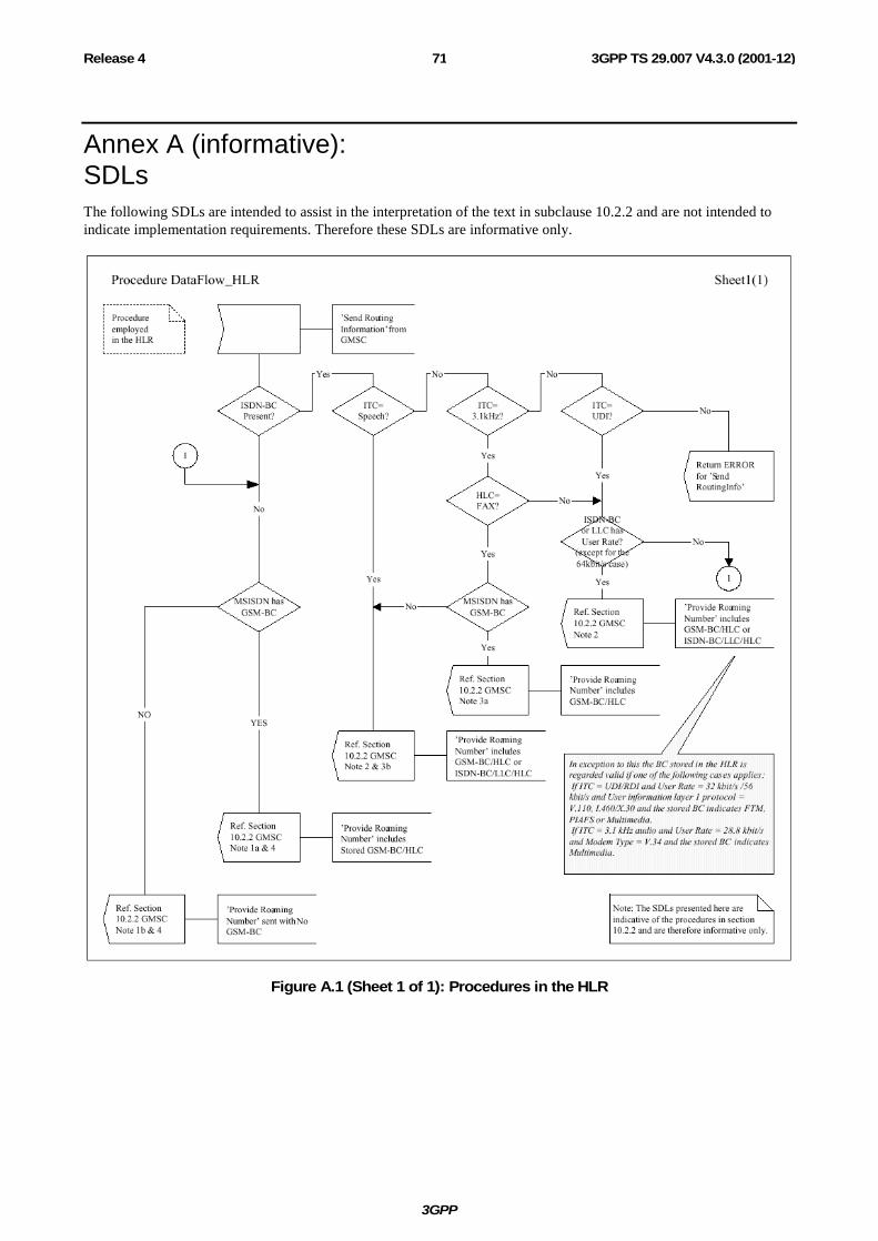
3GPP
3GPP TS 29.007 V4.3.0 (2001-12)71Release 4
Annex A (informative): SDLs The following SDLs are intended to assist in the interpretation of the text in subclause 10.2.2 and are not intended to indicate implementation requirements. Therefore these SDLs are informative only.
Figure A.1 (Sheet 1 of 1): Procedures in the HLR

3GPP
3GPP TS 29.007 V4.3.0 (2001-12)72Release 4
Figure A.2 (Sheet 1 of 1): Procedures in the MSC/VLR

3GPP
3GPP TS 29.007 V4.3.0 (2001-12)73Release 4
Annex B (informative): General mapping of V.24 circuits to channel status bits In the data transfer state, status bits SA, SB and X can be used to convey channel control information associated with the data bits. Table C1 shows the general mapping scheme between the V.24 circuit numbers and the status bits in the IWF. A binary 0 corresponds to the ON condition, a binary 1 to the OFF condition. The specific mappings for the various GSM bearer types are given elsewhere in the present document.
Since the V.24 circuits that are outputs from a DCE are inputs to a DTE (and vice versa), this mapping is the reverse of that used in the MT (3GPP TS 27.002, 3GPP TS 27.003).
For example, CT 109 is an output from the modem in the IWF and maps on to SB towards the MT. In the MT, SB is mapped on to CT 109 which is an input to the attached DTE.
Table B1: General mapping scheme at the IWF
Status bit direction: MS to IWF
Status bit direction: IWF to MS
Signal at IWF modem interface
SB 105 (note 3) X (note 1) 106 SA 107
SA 108 SB 109
X 133 (notes 2 and 3) NOTE 1: The condition of X towards the MS may also be affected by the state of any
transmit buffer in the IWF. NOTE 2: The condition of CT 133 towards the modem may also be affected by the state of
any receive buffer in the IWF or layer 2 flow control condition between the MT and IWF.
NOTE 3: CT105 and CT133 are assigned to the same connector pin on both the standard 25 pin connector (ISO/IEC 2110 [78]) and the commonly used 9 pin connector (annex B). When this pin is used for CT133 at the DTE/MT interface then on the MT side of the interface CT 105 is treated as being always in the ON condition. SB towards the IWF will therefore also always be ON.
Similarly, when this pin is being used for CT105 then on the MT side of the interface CT 133 is treated as being always in the ON condition. X towards the IWF will therefore also always be ON.
As circuit 133 is used only in duplex operation and circuit 105 is used only in half duplex operation (which is not supported by GSM/UMTS) there should be no conflict.

3GPP
3GPP TS 29.007 V4.3.0 (2001-12)74Release 4
Annex C (informative): Change history
Change history Date TSG # TSG Doc. CR Rev Subject/Comment Old New 1999-04 09.07 Transferred to 3GPP CN3 7.1.0 CN#03 Approved at CN#03 3.0.0 CN#04 001 Introduction of EDGE channel codings into the
specifications 3.0.0 3.1.0
CN#05 002 R99 Service Clean-up 3.1.0 3.2.0 CN#05 003 EDGE related corrections 3.1.0 3.2.0 CN#05 004 EDGE Asymmetric channel coding 3.1.0 3.2.0 CN#06 006 R99 service clean up 3.2.0 3.3.0 CN#06 007 Correction of intermediate rate values 3.2.0 3.3.0 CN#06 008 Introduction of Frame Tunnelling Mode 3.2.0 3.3.0 CN#06 009 Updates for UMTS 3.2.0 3.3.0 CN#06 010 Introduction of PIAFS and enhancement of processing at
mobile terminated call 3.2.0 3.3.0
CN#06 011 Multimedia call 3.2.0 3.3.0 CN#07 012 Change of reference from ETS 300102-1 to Q.931 3.3.0 3.4.0 CN#07 013 Handover between GSM and UMTS 3.3.0 3.4.0 CN#07 014 Changes to support fallback to speech in a circuit switched
multimedia call set-up 3.3.0 3.4.0
CN#08 015 Handover between 3G MSCs 3.4.0 3.5.0 CN#08 016 Rejection of lower user rates 3.4.0 3.5.0 CN#08 017 Fax 3.4.0 3.5.0 CN#08 018 Clarification of the VMSC behaviour in case of interworking 3.4.0 3.5.0 CN#08 019 Handover between 3G MSCs (Clarification for 56 and 64
kbit/s) 3.4.0 3.5.0
CN#08 020 ISDN TA function in case of bit transparent 56 kbit/s (RDI) and 64 kbit/s (UDI)
3.4.0 3.5.0
CN#08 021 33.6 kbit/s for multimedia 3.4.0 3.5.0 CN#09 022 Transparent 32 kbit/s data rate with I.460 rate adaptation 3.5.0 4.0.0 CN#09 025 Correction of incomplete part related to the introduction of
UMTS NT-RT FAX 3.5.0 4.0.0
CN#09 026 3.1 kHz multimedia at 33.6 kbit/s 3.5.0 4.0.0 CN#09 028 Clarification related to RCR 3.5.0 4.0.0 CN#09 029 32 kbit/s UDI/RDI multimedia 3.5.0 4.0.0 CN#10 032 Handover for 56kbit/s 4.0.0 4.1.0 CN#10 033 Removal of BS 30 NT 4.0.0 4.1.0 CN#11 035 A-TRAU' Correction 4.1.0 4.2.0 CN#11 037 A-TRAU' Synchronization 4.1.0 4.2.0 CN#11 038 Removal of FAX NT in GSM from Rel-4 4.1.0 4.2.0 CN#11 039 Introduction of Nb UP 4.1.0 4.2.0 2001-12 CN#14 NP-010571 043 Removal of Shared IWF 4.2.0 4.3.0 2001-12 CN#14 NP-010574 045 SDU size for transparent data at 33.6 kbit/s 4.2.0 4.3.0