ts 131 121 - v14.4.0 - universal mobile … · 3.5 generic procedures for...
TRANSCRIPT
ETSI TS 131 121 V14.4.0 (2018-04)
Universal Mobile Telecommunications System (UMTS); LTE;
UICC-terminal interface; Universal Subscriber Identity Module (USIM)
application test specification (3GPP TS 31.121 version 14.4.0 Release 14)
TECHNICAL SPECIFICATION

ETSI
ETSI TS 131 121 V14.4.0 (2018-04)13GPP TS 31.121 version 14.4.0 Release 14
Reference RTS/TSGC-0631121ve40
Keywords LTE,UMTS
ETSI
650 Route des Lucioles F-06921 Sophia Antipolis Cedex - FRANCE
Tel.: +33 4 92 94 42 00 Fax: +33 4 93 65 47 16
Siret N° 348 623 562 00017 - NAF 742 C
Association à but non lucratif enregistrée à la Sous-Préfecture de Grasse (06) N° 7803/88
Important notice
The present document can be downloaded from: http://www.etsi.org/standards-search
The present document may be made available in electronic versions and/or in print. The content of any electronic and/or print versions of the present document shall not be modified without the prior written authorization of ETSI. In case of any
existing or perceived difference in contents between such versions and/or in print, the only prevailing document is the print of the Portable Document Format (PDF) version kept on a specific network drive within ETSI Secretariat.
Users of the present document should be aware that the document may be subject to revision or change of status. Information on the current status of this and other ETSI documents is available at
https://portal.etsi.org/TB/ETSIDeliverableStatus.aspx
If you find errors in the present document, please send your comment to one of the following services: https://portal.etsi.org/People/CommiteeSupportStaff.aspx
Copyright Notification
No part may be reproduced or utilized in any form or by any means, electronic or mechanical, including photocopying and microfilm except as authorized by written permission of ETSI.
The content of the PDF version shall not be modified without the written authorization of ETSI. The copyright and the foregoing restriction extend to reproduction in all media.
© ETSI 2018.
All rights reserved.
DECTTM, PLUGTESTSTM, UMTSTM and the ETSI logo are trademarks of ETSI registered for the benefit of its Members. 3GPPTM and LTETM are trademarks of ETSI registered for the benefit of its Members and
of the 3GPP Organizational Partners. oneM2M logo is protected for the benefit of its Members.
GSM® and the GSM logo are trademarks registered and owned by the GSM Association.

ETSI
ETSI TS 131 121 V14.4.0 (2018-04)23GPP TS 31.121 version 14.4.0 Release 14
Intellectual Property Rights
Essential patents
IPRs essential or potentially essential to normative deliverables may have been declared to ETSI. The information pertaining to these essential IPRs, if any, is publicly available for ETSI members and non-members, and can be found in ETSI SR 000 314: "Intellectual Property Rights (IPRs); Essential, or potentially Essential, IPRs notified to ETSI in respect of ETSI standards", which is available from the ETSI Secretariat. Latest updates are available on the ETSI Web server (https://ipr.etsi.org/).
Pursuant to the ETSI IPR Policy, no investigation, including IPR searches, has been carried out by ETSI. No guarantee can be given as to the existence of other IPRs not referenced in ETSI SR 000 314 (or the updates on the ETSI Web server) which are, or may be, or may become, essential to the present document.
Trademarks
The present document may include trademarks and/or tradenames which are asserted and/or registered by their owners. ETSI claims no ownership of these except for any which are indicated as being the property of ETSI, and conveys no right to use or reproduce any trademark and/or tradename. Mention of those trademarks in the present document does not constitute an endorsement by ETSI of products, services or organizations associated with those trademarks.
Foreword This Technical Specification (TS) has been produced by ETSI 3rd Generation Partnership Project (3GPP).
The present document may refer to technical specifications or reports using their 3GPP identities, UMTS identities or GSM identities. These should be interpreted as being references to the corresponding ETSI deliverables.
The cross reference between GSM, UMTS, 3GPP and ETSI identities can be found under http://webapp.etsi.org/key/queryform.asp.
Modal verbs terminology In the present document "shall", "shall not", "should", "should not", "may", "need not", "will", "will not", "can" and "cannot" are to be interpreted as described in clause 3.2 of the ETSI Drafting Rules (Verbal forms for the expression of provisions).
"must" and "must not" are NOT allowed in ETSI deliverables except when used in direct citation.

ETSI
ETSI TS 131 121 V14.4.0 (2018-04)33GPP TS 31.121 version 14.4.0 Release 14
Contents
Intellectual Property Rights ................................................................................................................................ 2
Foreword ............................................................................................................................................................. 2
Modal verbs terminology .................................................................................................................................... 2
Foreword ........................................................................................................................................................... 20
Introduction ...................................................................................................................................................... 20
1 Scope ...................................................................................................................................................... 21
2 References .............................................................................................................................................. 21
3 Definitions, symbols, abbreviations and coding ..................................................................................... 23
3.1 Definitions ........................................................................................................................................................ 23
3.2 Symbols ............................................................................................................................................................ 24
3.3 Abbreviations ................................................................................................................................................... 24
3.4 Coding Conventions ......................................................................................................................................... 26
3.5 Generic procedures for E-UTRAN/UTRAN/GERAN/IMSNB-IoT ................................................................ 26
3.6 Applicability ..................................................................................................................................................... 27
3.6.1 Applicability of the present document ........................................................................................................ 27
3.6.2 Applicability to terminal equipment ........................................................................................................... 27
3.6.3 Applicability of the individual tests ............................................................................................................ 27
3.7 Table of optional features ................................................................................................................................. 28
3.8 Applicability table ............................................................................................................................................ 30
4 Default Values ........................................................................................................................................ 47
4.1 Definition of default values for USIM-Terminal interface testing (Default UICC) ......................................... 47
4.1.1 Values of the EF's (Default UICC) ............................................................................................................. 47
4.1.1.1 EFIMSI (IMSI) ........................................................................................................................................ 47
4.1.1.2 EFAD (Administrative Data) .................................................................................................................. 47
4.1.1.3 EFLOCI (Location Information) .............................................................................................................. 47
4.1.1.4 EFKeys (Ciphering and Integrity Keys) .................................................................................................. 48
4.1.1.5 EFKeysPS (Ciphering and Integrity Keys for Packet Switched domain) .................................................. 48
4.1.1.6 EFACC (Access Control Class) ............................................................................................................... 48
4.1.1.7 EFFPLMN (Forbidden PLMNs) ................................................................................................................ 48
4.1.1.8 EFUST (USIM Service Table) ................................................................................................................ 48
4.1.1.9 EFEST (Enable Service Table) ................................................................................................................ 49
4.1.1.10 EFADN (Abbreviated Dialling Number) ................................................................................................. 49
4.1.1.11 EFPLMNwACT (User Controlled PLMN Selector with Access Technology) ............................................ 49
4.1.1.12 EFOPLMNwACT (Operator Controlled PLMN Selector with Access Technology) .................................... 50
4.1.1.13 Void....................................................................................................................................................... 50
4.1.1.14 PIN ........................................................................................................................................................ 50
4.1.1.15 PIN2 ...................................................................................................................................................... 51
4.1.1.16 Unblock PIN ......................................................................................................................................... 51
4.1.1.17 Unblock PIN2 ....................................................................................................................................... 51
4.1.1.18 Other Values of the USIM .................................................................................................................... 51
4.1.1.19 EFPSLOCI (Packet Switch Location Information) .................................................................................... 51
4.1.1.20 Universal PIN ........................................................................................................................................ 51
4.1.1.21 Unblock Universal PIN ......................................................................................................................... 52
4.2 Definition of FDN UICC .................................................................................................................................. 52
4.2.1 Values of the EF's (FDN UICC) ................................................................................................................. 52
4.2.1.1 EFUST (USIM Service Table) ................................................................................................................ 52
4.2.1.2 EFEST (Enable Service Table) ................................................................................................................ 52
4.2.1.3 EFFDN (Fixed Dialling Numbers) .......................................................................................................... 52
4.2.1.4 EFECC (Emergency Call Codes) ............................................................................................................. 53
4.2.1.5 Other Values of the USIM .................................................................................................................... 53
4.3 Void .................................................................................................................................................................. 54
4.4 Definition of E-UTRAN/EPC UICC ................................................................................................................ 54
4.4.1 EFUST (USIM Service Table) ................................................................................................................ 54

ETSI
ETSI TS 131 121 V14.4.0 (2018-04)43GPP TS 31.121 version 14.4.0 Release 14
4.4.2 EFEPSLOCI (EPS Information) ................................................................................................................. 54
4.4.3 EFPLMNwACT (User Controlled PLMN Selector with Access Technology) ............................................ 54
4.4.4 EFOPLMNwACT (Operator Controlled PLMN Selector with Access Technology) .................................... 55
4.4.5 EFACSGL (Allowed CSG Lists) ............................................................................................................... 56
4.4.6 EFCSGT (CSG Type) ............................................................................................................................... 56
4.4.7 EFHNBN (Home (e)NodeB Name) .......................................................................................................... 58
4.4.8 EFEPSNSC (EPS NAS Security Context) ................................................................................................. 59
4.5 Definition of E-UTRAN/EPC ISIM-UICC ...................................................................................................... 60
4.5.1 Applications on the E-UTRAN/EPC ISIM-UICC ................................................................................ 60
4.5.2 Default USIM values on E-UTRAN/EPC ISIM-UICC ......................................................................... 60
4.5.3 Default ISIM values on E-UTRAN/EPC ISIM-UICC .......................................................................... 60
4.5.3.1 EFAD (Administrative Data) .................................................................................................................. 60
4.5.3.2 EFIST (ISIM Service Table) ................................................................................................................... 60
4.5.3.3 EFIMPI (IMS private user identity) ......................................................................................................... 60
4.5.3.4 EFDOMAIN (Home Network Domain Name) ........................................................................................... 61
4.5.3.5 EFIMPU (IMS public user identity) ......................................................................................................... 61
4.5.3.6 EFP-CSCF (P-CSCF ADDRESS) ............................................................................................................. 62
4.5.3.7 EFSMS (Short Message Service) ............................................................................................................. 62
4.5.3.8 EFSMSR (Short message status reports) .................................................................................................. 62
4.5.3.9 EFSMSP (Short message service parameters) .......................................................................................... 63
4.5.3.10 EFSMSS (SMS Status) ............................................................................................................................. 63
4.5.4 Default values at DF_TELECOM ......................................................................................................... 63
4.5.4.1 EFPSISMSC (Public Service Identity of the SM-SC) ................................................................................ 63
4.6 Definition of ACSGL/OCSGL E-UTRAN/EPC UICC .................................................................................... 64
4.6.1 EFUST (USIM Service Table) ................................................................................................................ 64
4.6.2 EFAD (Administrative Data) .................................................................................................................. 64
4.6.3 EFOCSGL (Operator CSG Lists) .............................................................................................................. 64
4.6.4 EFOCSGT (Operator CSG Type) .............................................................................................................. 65
4.6.5 EFOHNBN (Operator Home (e)NodeB Name) ......................................................................................... 66
4.7.1 Values of the EFs ........................................................................................................................................ 68
4.7.1.1 EFUST (USIM Service Table) ................................................................................................................ 68
4.7.1.2 EFNASCONFIG (Non Access Stratum Configuration) ................................................................................ 68
5 Subscription related tests ........................................................................................................................ 75
5.1 IMSI / TMSI handling ...................................................................................................................................... 75
5.1.1 UE identification by short IMSI ................................................................................................................. 75
5.1.1.1 Definition and applicability ................................................................................................................... 75
5.1.1.2 Conformance requirement ..................................................................................................................... 75
5.1.1.3 Test purpose .......................................................................................................................................... 76
5.1.1.4 Method of test ....................................................................................................................................... 76
5.1.1.4.1 Initial conditions .............................................................................................................................. 76
5.1.1.4.2 Procedure ......................................................................................................................................... 76
5.1.1.5 Acceptance criteria ................................................................................................................................ 76
5.1.2 UE identification by short IMSI using a 2 digit MNC ................................................................................ 76
5.1.2.1 Definition and applicability ................................................................................................................... 76
5.1.2.2 Conformance requirement ..................................................................................................................... 77
5.1.2.3 Test purpose .......................................................................................................................................... 77
5.1.2.4 Method of test ....................................................................................................................................... 77
5.1.2.4.1 Initial conditions .............................................................................................................................. 77
5.1.2.4.2 Procedure ......................................................................................................................................... 78
5.1.2.5 Acceptance criteria ................................................................................................................................ 78
5.1.3 UE identification by "short" TMSI ............................................................................................................. 78
5.1.3.1 Definition and applicability ................................................................................................................... 78
5.1.3.2 Conformance requirement ..................................................................................................................... 78
5.1.3.3 Test purpose .......................................................................................................................................... 78
5.1.3.4 Method of test ....................................................................................................................................... 79
5.1.3.4.1 Initial conditions .............................................................................................................................. 79
5.1.3.4.2 Procedure ......................................................................................................................................... 79
5.1.3.5 Acceptance criteria ................................................................................................................................ 79
5.1.4 UE identification by "long" TMSI .............................................................................................................. 80
5.1.4.1 Definition and applicability ................................................................................................................... 80
5.1.4.2 Conformance requirement ..................................................................................................................... 80

ETSI
ETSI TS 131 121 V14.4.0 (2018-04)53GPP TS 31.121 version 14.4.0 Release 14
5.1.4.3 Test purpose .......................................................................................................................................... 80
5.1.4.4 Method of test ....................................................................................................................................... 80
5.1.4.4.1 Initial conditions .............................................................................................................................. 80
5.1.4.4.2 Procedure ......................................................................................................................................... 81
5.1.4.5 Acceptance criteria ................................................................................................................................ 81
5.1.5 UE identification by long IMSI, TMSI updating and key set identifier assignment ................................... 81
5.1.5.1 Definition and applicability ................................................................................................................... 81
5.1.5.2 Conformance requirement ..................................................................................................................... 82
5.1.5.3 Test purpose .......................................................................................................................................... 82
5.1.5.4 Method of test ....................................................................................................................................... 82
5.1.5.4.1 Initial conditions .............................................................................................................................. 82
5.1.5.4.2 Procedure ......................................................................................................................................... 83
5.1.5.5 Acceptance criteria ................................................................................................................................ 84
5.1.6 UE identification by short IMSI when accessing E-UTRAN/EPC ............................................................. 84
5.1.6.1 Definition and applicability ................................................................................................................... 84
5.1.6.2 Conformance requirement ..................................................................................................................... 84
5.1.6.3 Test purpose .......................................................................................................................................... 85
5.1.6.4 Method of test ....................................................................................................................................... 85
5.1.6.4.1 Initial conditions .............................................................................................................................. 85
5.1.6.4.2 Procedure ......................................................................................................................................... 85
5.1.6.5 Acceptance criteria ................................................................................................................................ 85
5.1.7 UE identification by short IMSI using a 2 digit MNC when accessing E-UTRAN/EPC ........................... 86
5.1.7.1 Definition and applicability ................................................................................................................... 86
5.1.7.2 Conformance requirement ..................................................................................................................... 86
5.1.7.3 Test purpose .......................................................................................................................................... 86
5.1.7.4 Method of test ....................................................................................................................................... 86
5.1.7.4.1 Initial conditions .............................................................................................................................. 86
5.1.7.4.2 Procedure ......................................................................................................................................... 87
5.1.7.5 Acceptance criteria ................................................................................................................................ 87
5.1.8 UE identification after changed IMSI with service "EMM Information" not available ............................. 87
5.1.8.2 Conformance requirement ..................................................................................................................... 87
5.1.8.3 Test purpose .......................................................................................................................................... 88
5.1.8.4 Method of test ....................................................................................................................................... 88
5.1.8.4.1 Initial conditions .............................................................................................................................. 88
5.1.8.4.2 Procedure ......................................................................................................................................... 88
5.1.8.5 Acceptance criteria ................................................................................................................................ 88
5.1.9 UE identification by GUTI when using USIM with service "EMM Information" not available ................ 89
5.1.9.2 Conformance requirement ..................................................................................................................... 89
5.1.9.3 Test purpose .......................................................................................................................................... 89
5.1.9.4 Method of test ....................................................................................................................................... 89
5.1.9.4.1 Initial conditions .............................................................................................................................. 89
5.1.9.4.2 Procedure ......................................................................................................................................... 89
5.1.9.5 Acceptance criteria ................................................................................................................................ 90
5.1.10 UE identification by GUTI when using USIM with service "EMM Information" available ...................... 90
5.1.10.1 Definition and applicability ................................................................................................................... 90
5.1.10.2 Conformance requirement ..................................................................................................................... 90
5.1.10.3 Test purpose .......................................................................................................................................... 91
5.1.10.4 Method of test ....................................................................................................................................... 91
5.1.10.4.1 Initial conditions .............................................................................................................................. 91
5.1.10.4.2 Procedure ......................................................................................................................................... 91
5.1.10.5 Acceptance criteria ................................................................................................................................ 91
5.2 Access Control handling .................................................................................................................................. 92
5.2.1 Access Control information handling ......................................................................................................... 92
5.2.1.1 Definition and applicability ................................................................................................................... 92
5.2.1.2 Conformance requirement ..................................................................................................................... 92
5.2.1.3 Test purpose .......................................................................................................................................... 93
5.2.1.4 Method of test ....................................................................................................................................... 93
5.2.1.4.1 Initial conditions .............................................................................................................................. 93
5.2.1.4.2 Coding details .................................................................................................................................. 93
5.2.1.4.3 Procedure ......................................................................................................................................... 94
5.2.1.5 Acceptance criteria ................................................................................................................................ 94
5.2.2 Access Control information handling for E-UTRAN/EPC ....................................................................... 106

ETSI
ETSI TS 131 121 V14.4.0 (2018-04)63GPP TS 31.121 version 14.4.0 Release 14
5.2.2.1 Definition and applicability ................................................................................................................. 106
5.2.2.2 Conformance requirement ................................................................................................................... 106
5.2.2.3 Test purpose ........................................................................................................................................ 106
5.2.2.4 Method of test ..................................................................................................................................... 106
5.2.2.4.1 Initial conditions ............................................................................................................................ 106
5.2.2.4.2 Coding details ................................................................................................................................ 107
5.2.2.4.3 Procedure ....................................................................................................................................... 107
5.2.2.5 Acceptance criteria .............................................................................................................................. 107
6 Security related Tests ........................................................................................................................... 131
6.1 PIN handling .................................................................................................................................................. 131
6.1.1 Entry of PIN .............................................................................................................................................. 131
6.1.1.1 Definition and applicability ................................................................................................................. 131
6.1.1.2 Conformance requirement ................................................................................................................... 131
6.1.1.3 Test purpose ........................................................................................................................................ 132
6.1.1.4 Method of test ..................................................................................................................................... 132
6.1.1.4.1 Initial conditions ............................................................................................................................ 132
6.1.1.4.2 Procedure ....................................................................................................................................... 132
6.1.1.5 Acceptance criteria .............................................................................................................................. 132
6.1.2 Change of PIN .......................................................................................................................................... 132
6.1.2.1 Definition and applicability ................................................................................................................. 132
6.1.2.2 Conformance requirement ................................................................................................................... 132
6.1.2.3 Test purpose ........................................................................................................................................ 132
6.1.2.4 Method of test ..................................................................................................................................... 132
6.1.2.4.1 Initial conditions ............................................................................................................................ 132
6.1.2.4.2 Procedure ....................................................................................................................................... 133
6.1.2.5 Acceptance criteria .............................................................................................................................. 133
6.1.3 Unblock PIN ............................................................................................................................................. 133
6.1.3.1 Definition and applicability ................................................................................................................. 133
6.1.3.2 Conformance requirement ................................................................................................................... 133
6.1.3.3 Test purpose ........................................................................................................................................ 133
6.1.3.4 Method of test ..................................................................................................................................... 133
6.1.3.4.1 Initial conditions ............................................................................................................................ 133
6.1.3.4.2 Procedure ....................................................................................................................................... 133
6.1.3.5 Acceptance criteria .............................................................................................................................. 134
6.1.4 Entry of PIN2 ............................................................................................................................................ 134
6.1.4.1 Definition and applicability ................................................................................................................. 134
6.1.4.2 Conformance requirement ................................................................................................................... 135
6.1.4.3 Test purpose ........................................................................................................................................ 135
6.1.4.4 Method of test ..................................................................................................................................... 135
6.1.4.4.1 Initial conditions ............................................................................................................................ 135
6.1.4.4.2 Procedure ....................................................................................................................................... 135
6.1.4.5 Acceptance criteria .............................................................................................................................. 135
6.1.5 Change of PIN2 ........................................................................................................................................ 135
6.1.5.1 Definition and applicability ................................................................................................................. 135
6.1.5.2 Conformance requirement ................................................................................................................... 135
6.1.5.3 Test purpose ........................................................................................................................................ 136
6.1.5.4 Method of test ..................................................................................................................................... 136
6.1.5.4.1 Initial conditions ............................................................................................................................ 136
6.1.5.4.2 Procedure ....................................................................................................................................... 136
6.1.5.5 Acceptance criteria .............................................................................................................................. 136
6.1.6 Unblock PIN2 ........................................................................................................................................... 136
6.1.6.1 Definition and applicability ................................................................................................................. 136
6.1.6.2 Conformance requirement ................................................................................................................... 136
6.1.6.3 Test purpose ........................................................................................................................................ 137
6.1.6.4 Method of test ..................................................................................................................................... 137
6.1.6.4.1 Initial conditions ............................................................................................................................ 137
6.1.6.4.2 Procedure ....................................................................................................................................... 137
6.1.6.5 Acceptance criterias ............................................................................................................................ 138
6.1.7 Replacement of PIN .................................................................................................................................. 138
6.1.7.1 Definition and applicability ................................................................................................................. 138
6.1.7.2 Conformance requirement ................................................................................................................... 138
ETSI
ETSI TS 131 121 V14.4.0 (2018-04)73GPP TS 31.121 version 14.4.0 Release 14
6.1.7.3 Test purpose ........................................................................................................................................ 138
6.1.7.4 Method of test ..................................................................................................................................... 138
6.1.7.4.1 Initial conditions ............................................................................................................................ 138
6.1.7.4.2 Procedure ....................................................................................................................................... 138
6.1.7.5 Acceptance criteria .............................................................................................................................. 139
6.1.8 Change of Universal PIN .......................................................................................................................... 139
6.1.8.1 Definition and applicability ................................................................................................................. 139
6.1.8.2 Conformance requirement ................................................................................................................... 139
6.1.8.3 Test purpose ........................................................................................................................................ 139
6.1.8.4 Method of test ..................................................................................................................................... 140
6.1.8.4.1 Initial conditions ............................................................................................................................ 140
6.1.8.4.2 Procedure ....................................................................................................................................... 140
6.1.8.5 Acceptance criteria .............................................................................................................................. 140
6.1.9 Unblock Universal PIN ............................................................................................................................. 140
6.1.9.1 Definition and applicability ................................................................................................................. 140
6.1.9.2 Conformance requirement ................................................................................................................... 140
6.1.9.3 Test purpose ........................................................................................................................................ 140
6.1.9.4 Method of test ..................................................................................................................................... 140
6.1.9.4.1 Initial conditions ............................................................................................................................ 140
6.1.9.4.2 Procedure ....................................................................................................................................... 141
6.1.9.5 Acceptance criteria .............................................................................................................................. 141
6.1.10 Entry of PIN on multi-verification capable UICCs ................................................................................... 141
6.1.10.1 Definition and applicability ................................................................................................................. 141
6.1.10.2 Conformance requirement ................................................................................................................... 141
6.1.10.3 Test purpose ........................................................................................................................................ 141
6.1.10.4 Method of test ..................................................................................................................................... 142
6.1.10.4.1 Initial conditions ............................................................................................................................ 142
6.1.10.4.2 Procedure ....................................................................................................................................... 142
6.1.10.5 Acceptance criteria .............................................................................................................................. 142
6.1.11 Change of PIN on multi-verification capable UICCs ............................................................................... 143
6.1.11.1 Definition and applicability ................................................................................................................. 143
6.1.11.2 Conformance requirement ................................................................................................................... 143
6.1.11.3 Test purpose ........................................................................................................................................ 143
6.1.11.4 Method of test ..................................................................................................................................... 143
6.1.11.4.1 Initial conditions ............................................................................................................................ 143
6.1.11.4.2 Procedure ....................................................................................................................................... 144
6.1.11.5 Acceptance criteria .............................................................................................................................. 144
6.1.12 Unblock PIN on multi-verification capable UICCs .................................................................................. 144
6.1.12.1 Definition and applicability ................................................................................................................. 144
6.1.12.2 Conformance requirement ................................................................................................................... 144
6.1.12.3 Test purpose ........................................................................................................................................ 145
6.1.12.4 Method of test ..................................................................................................................................... 145
6.1.12.4.1 Initial conditions ............................................................................................................................ 145
6.1.12.4.2 Procedure ....................................................................................................................................... 145
6.1.12.5 Acceptance criteria .............................................................................................................................. 146
6.1.13 Entry of PIN2 on multi-verification capable UICCs ................................................................................. 146
6.1.13.1 Definition and applicability ................................................................................................................. 146
6.1.13.2 Conformance requirement ................................................................................................................... 146
6.1.13.3 Test purpose ........................................................................................................................................ 147
6.1.13.4 Method of test ..................................................................................................................................... 147
6.1.13.4.1 Initial conditions ............................................................................................................................ 147
6.1.13.4.2 Procedure ....................................................................................................................................... 148
6.1.13.5 Acceptance criteria .............................................................................................................................. 148
6.1.14 Change of PIN2 on multi-verification capable UICCs ............................................................................. 148
6.1.14.1 Definition and applicability ................................................................................................................. 148
6.1.14.2 Conformance requirement ................................................................................................................... 148
6.1.14.3 Test purpose ........................................................................................................................................ 148
6.1.14.4 Method of test ..................................................................................................................................... 148
6.1.14.4.1 Initial conditions ............................................................................................................................ 148
6.1.14.4.2 Procedure ....................................................................................................................................... 149
6.1.14.5 Acceptance criteria .............................................................................................................................. 149
6.1.15 Unblock PIN2 on multi-verification capable UICCs ................................................................................ 150

ETSI
ETSI TS 131 121 V14.4.0 (2018-04)83GPP TS 31.121 version 14.4.0 Release 14
6.1.15.1 Definition and applicability ................................................................................................................. 150
6.1.15.2 Conformance requirement ................................................................................................................... 150
6.1.15.3 Test purpose ........................................................................................................................................ 150
6.1.15.4 Method of test ..................................................................................................................................... 150
6.1.15.4.1 Initial conditions ............................................................................................................................ 150
6.1.15.4.2 Procedure ....................................................................................................................................... 151
6.1.15.5 Acceptance criterias ............................................................................................................................ 152
6.1.16 Replacement of PIN with key reference "07" ........................................................................................... 152
6.1.16.1 Definition and applicability ................................................................................................................. 152
6.1.16.2 Conformance requirement ................................................................................................................... 152
6.1.16.3 Test purpose ........................................................................................................................................ 152
6.1.16.4 Method of test ..................................................................................................................................... 152
6.1.16.4.1 Initial conditions ............................................................................................................................ 152
6.1.16.4.2 Procedure ....................................................................................................................................... 153
6.1.16.5 Acceptance criteria .............................................................................................................................. 153
6.2 Fixed Dialling Numbers (FDN) handling ....................................................................................................... 154
6.2.1 Terminal and USIM with FDN enabled, EFADN readable and updateable ................................................ 154
6.2.1.1 Definition and applicability ................................................................................................................. 154
6.2.1.2 Conformance requirement ................................................................................................................... 154
6.2.1.3 Test purpose ........................................................................................................................................ 154
6.2.1.4 Method of test ..................................................................................................................................... 155
6.2.1.4.1 Initial conditions ............................................................................................................................ 155
6.2.1.4.2 Procedure ....................................................................................................................................... 155
6.2.1.5 Acceptance criteria .............................................................................................................................. 156
6.2.2 Terminal and USIM with FDN disabled ................................................................................................... 156
6.2.2.1 Definition and applicability ................................................................................................................. 156
6.2.2.2 Conformance requirement ................................................................................................................... 156
6.2.2.3 Test purpose ........................................................................................................................................ 156
6.2.2.4 Method of test ..................................................................................................................................... 156
6.2.2.4.1 Initial conditions ............................................................................................................................ 156
6.2.2.4.2 Procedure ....................................................................................................................................... 157
6.2.2.5 Acceptance criteria .............................................................................................................................. 157
6.2.3 Enabling, disabling and updating of FDN ................................................................................................ 157
6.2.3.1 Definition and applicability ................................................................................................................. 157
6.2.3.2 Conformance requirement ................................................................................................................... 157
6.2.3.3 Test purpose ........................................................................................................................................ 157
6.2.3.4 Method of test ..................................................................................................................................... 158
6.2.3.4.1 Initial conditions ............................................................................................................................ 158
6.2.3.4.2 Procedure ....................................................................................................................................... 158
6.2.3.5 Acceptance criteria .............................................................................................................................. 158
6.2.4 Terminal and USIM with FDN enabled, EFADN readable and updateable (Rel-4 and onwards) .............. 158
6.2.4.1 Definition and applicability ................................................................................................................. 158
6.2.4.2 Conformance requirement ................................................................................................................... 158
6.2.4.3 Test purpose ........................................................................................................................................ 159
6.2.4.4 Method of test ..................................................................................................................................... 159
6.2.4.4.1 Initial conditions ............................................................................................................................ 159
6.2.4.4.2 Procedure ....................................................................................................................................... 159
6.2.4.5 Acceptance criteria .............................................................................................................................. 160
6.3 Void ................................................................................................................................................................ 160
6.4 Advice of charge (AoC) handling .................................................................................................................. 160
6.4.1 AoC not supported by USIM .................................................................................................................... 160
6.4.1.1 Definition and applicability ................................................................................................................. 160
6.4.1.2 Conformance requirement ................................................................................................................... 160
6.4.1.3 Test purpose ........................................................................................................................................ 161
6.4.1.4 Method of test ..................................................................................................................................... 161
6.4.1.4.1 Initial conditions ............................................................................................................................ 161
6.4.1.4.2 Procedure ....................................................................................................................................... 161
6.4.1.5 Acceptance criteria .............................................................................................................................. 162
6.4.2 Maximum frequency of ACM updating.................................................................................................... 162
6.4.2.1 Definition and applicability ................................................................................................................. 162
6.4.2.2 Conformance requirement ................................................................................................................... 162
6.4.2.3 Test purpose ........................................................................................................................................ 162

ETSI
ETSI TS 131 121 V14.4.0 (2018-04)93GPP TS 31.121 version 14.4.0 Release 14
6.4.2.4 Method of test ..................................................................................................................................... 162
6.4.2.4.1 Initial conditions ............................................................................................................................ 162
6.4.2.4.2 Procedure ....................................................................................................................................... 163
6.4.2.5 Acceptance criteria .............................................................................................................................. 165
6.4.3 Call terminated when ACM greater than ACMmax ................................................................................. 165
6.4.3.1 Definition and applicability ................................................................................................................. 165
6.4.3.2 Conformance requirement ................................................................................................................... 165
6.4.3.3 Test purpose ........................................................................................................................................ 165
6.4.3.4 Method of test ..................................................................................................................................... 166
6.4.3.4.1 Initial conditions ............................................................................................................................ 166
6.4.3.4.2 Procedure ....................................................................................................................................... 166
6.4.3.5 Acceptance criteria .............................................................................................................................. 168
6.4.4 Response codes of increase command of ACM ........................................................................................ 168
6.4.4.1 Definition and applicability ................................................................................................................. 168
6.4.4.2 Conformance requirement ................................................................................................................... 169
6.4.4.3 Test purpose ........................................................................................................................................ 169
6.4.4.4 Method of test ..................................................................................................................................... 169
6.4.4.4.1 Initial conditions ............................................................................................................................ 169
6.4.4.4.2 Procedure ....................................................................................................................................... 170
6.4.4.5 Acceptance criteria .............................................................................................................................. 172
7 PLMN related tests ............................................................................................................................... 173
7.1 FPLMN handling ............................................................................................................................................ 173
7.1.1 Adding FPLMN to the Forbidden PLMN list ........................................................................................... 173
7.1.1.1 Definition and applicability ................................................................................................................. 173
7.1.1.2 Conformance requirement ................................................................................................................... 173
7.1.1.3 Test purpose ........................................................................................................................................ 175
7.1.1.4 Method of test ..................................................................................................................................... 175
7.1.1.4.1 Initial conditions ............................................................................................................................ 175
7.1.1.4.2 Procedure ....................................................................................................................................... 176
7.1.1.5 Acceptance criteria .............................................................................................................................. 179
7.1.2 UE updating forbidden PLMNs ................................................................................................................ 181
7.1.2.1 Definition and applicability ................................................................................................................. 181
7.1.2.2 Conformance requirement ................................................................................................................... 182
7.1.2.3 Test purpose ........................................................................................................................................ 182
7.1.2.4 Method of test ..................................................................................................................................... 182
7.1.2.4.1 Initial conditions ............................................................................................................................ 182
7.1.2.4.2 Procedure ....................................................................................................................................... 183
7.1.2.5 Acceptance criteria .............................................................................................................................. 184
7.1.3 UE deleting forbidden PLMNs ................................................................................................................. 184
7.1.3.1 Definition and applicability ................................................................................................................. 184
7.1.3.2 Conformance requirement ................................................................................................................... 185
7.1.3.3 Test purpose ........................................................................................................................................ 185
7.1.3.4 Method of test ..................................................................................................................................... 186
7.1.3.4.1 Initial conditions ............................................................................................................................ 186
7.1.3.4.2 Procedure ....................................................................................................................................... 186
7.1.3.5 Acceptance criteria .............................................................................................................................. 187
7.1.4 Adding FPLMN to the forbidden PLMN list when accessing E-UTRAN ................................................ 188
7.1.4.1 Definition and applicability ................................................................................................................. 188
7.1.4.2 Conformance requirement ................................................................................................................... 189
7.1.4.3 Test purpose ........................................................................................................................................ 189
7.1.4.4 Method of test ..................................................................................................................................... 189
7.1.4.4.1 Initial conditions ............................................................................................................................ 189
7.1.4.4.2 Procedure ....................................................................................................................................... 190
7.1.4.5 Acceptance criteria .............................................................................................................................. 191
7.1.5 UE updating forbidden PLMNs when accessing E-UTRAN .................................................................... 191
7.1.5.1 Definition and applicability ................................................................................................................. 191
7.1.5.2 Conformance requirement ................................................................................................................... 191
7.1.5.3 Test purpose ........................................................................................................................................ 192
7.1.5.4 Method of test ..................................................................................................................................... 192
7.1.5.4.1 Initial conditions ............................................................................................................................ 192
7.1.5.4.2 Procedure ....................................................................................................................................... 192

ETSI
ETSI TS 131 121 V14.4.0 (2018-04)103GPP TS 31.121 version 14.4.0 Release 14
7.1.5.5 Acceptance criteria .............................................................................................................................. 192
7.1.6 UE deleting forbidden PLMNs when accessing E-UTRAN ..................................................................... 193
7.1.6.1 Definition and applicability ................................................................................................................. 193
7.1.6.2 Conformance requirement ................................................................................................................... 193
7.1.6.3 Test purpose ........................................................................................................................................ 193
7.1.6.4 Method of test ..................................................................................................................................... 194
7.1.6.4.1 Initial conditions ............................................................................................................................ 194
7.1.6.4.2 Procedure ....................................................................................................................................... 194
7.1.6.5 Acceptance criteria .............................................................................................................................. 194
7.1.7 Updating the Forbidden PLMN list after receiving non-integrity protected reject message – UTRAN .. 195
7.1.7.1 Definition and applicability ................................................................................................................. 195
7.1.7.2 Conformance requirement ................................................................................................................... 195
7.1.7.3 Test purpose ........................................................................................................................................ 196
7.1.7.4 Method of test ..................................................................................................................................... 196
7.1.7.4.1 Initial conditions ............................................................................................................................ 196
7.1.7.4.2 Procedure ....................................................................................................................................... 196
7.1.7.5 Acceptance criteria .............................................................................................................................. 197
7.1.8 Updating the Forbidden PLMN list after receiving non-integrity protected reject message – E-UTRAN .................................................................................................................................................... 197
7.1.8.1 Definition and applicability ................................................................................................................. 197
7.1.8.2 Conformance requirement ................................................................................................................... 197
7.1.8.3 Test purpose ........................................................................................................................................ 198
7.1.8.4 Method of test ..................................................................................................................................... 198
7.1.8.4.1 Initial conditions ............................................................................................................................ 198
7.1.8.4.2 Procedure ....................................................................................................................................... 199
7.1.8.5 Acceptance criteria .............................................................................................................................. 199
7.2 User controlled PLMN selector handling ....................................................................................................... 200
7.2.1 UE updating the User controlled PLMN selector list ............................................................................... 200
7.2.1.1 Definition and applicability ................................................................................................................. 200
7.2.1.2 Conformance requirement ................................................................................................................... 200
7.2.1.3 Test purpose ........................................................................................................................................ 200
7.2.1.4 Method of test ..................................................................................................................................... 200
7.2.1.4.1 Initial conditions ............................................................................................................................ 200
7.2.1.4.2 Procedure ....................................................................................................................................... 200
7.2.1.5 Acceptance criteria .............................................................................................................................. 200
7.2.2 UE recognising the priority order of the User controlled PLMN selector list with the same access technology................................................................................................................................................. 201
7.2.2.1 Definition and applicability ................................................................................................................. 201
7.2.2.2 Conformance requirement ................................................................................................................... 201
7.2.2.3 Test purpose ........................................................................................................................................ 201
7.2.2.4 Method of test ..................................................................................................................................... 201
7.2.2.4.1 Initial conditions ............................................................................................................................ 201
7.2.2.4.2 Procedure ....................................................................................................................................... 202
7.2.2.5 Acceptance criteria .............................................................................................................................. 204
7.2.3 UE recognising the priority order of the User controlled PLMN selector list using an ACT preference. ................................................................................................................................................ 205
7.2.3.1 Definition and applicability ................................................................................................................. 205
7.2.3.2 Conformance requirement ................................................................................................................... 205
7.2.3.3 Test purpose .................................................................................................................................. 205
7.2.3.4 Method of test ..................................................................................................................................... 205
7.2.3.4.1 Initial conditions ............................................................................................................................ 205
7.2.3.4.2 Procedure ....................................................................................................................................... 205
7.2.3.5 Acceptance criteria .............................................................................................................................. 206
7.2.4 Void .......................................................................................................................................................... 206
7.2.5 UE updating the User controlled PLMN selector list for E-UTRAN ....................................................... 206
7.2.5.1 Definition and applicability ................................................................................................................. 206
7.2.5.2 Conformance requirement ................................................................................................................... 207
7.2.5.3 Test purpose ........................................................................................................................................ 207
7.2.5.4 Method of test ..................................................................................................................................... 207
7.2.5.4.1 Initial conditions ............................................................................................................................ 207
7.2.5.4.2 Procedure ....................................................................................................................................... 207
7.2.5.5 Acceptance criteria .............................................................................................................................. 207

ETSI
ETSI TS 131 121 V14.4.0 (2018-04)113GPP TS 31.121 version 14.4.0 Release 14
7.2.6 UE recognising the priority order of the User controlled PLMN selector list using an ACT preference- UTRAN/E-UTRAN ............................................................................................................... 208
7.2.6.1 Definition and applicability ................................................................................................................. 208
7.2.6.2 Conformance requirement ................................................................................................................... 208
7.2.6.3 Test purpose .................................................................................................................................. 208
7.2.6.4 Method of test ..................................................................................................................................... 208
7.2.6.4.1 Initial conditions ............................................................................................................................ 208
7.2.6.4.2 Procedure ....................................................................................................................................... 209
7.2.6.5 Acceptance criteria .............................................................................................................................. 209
7.2.7 UE recognising the priority order of the User controlled PLMN selector list using an ACT preference- GSM/E-UTRAN .................................................................................................................... 209
7.2.7.1 Definition and applicability ................................................................................................................. 209
7.2.7.2 Conformance requirement ................................................................................................................... 210
7.2.7.3 Test purpose .................................................................................................................................. 210
7.2.7.4 Method of test ..................................................................................................................................... 210
7.2.7.4.1 Initial conditions ............................................................................................................................ 210
7.2.7.4.2 Procedure ....................................................................................................................................... 210
7.2.7.5 Acceptance criteria .............................................................................................................................. 210
7.3 Operator controlled PLMN selector handling ................................................................................................ 211
7.3.1 UE recognising the priority order of the Operator controlled PLMN selector list. ................................... 211
7.3.1.1 Definition and applicability ................................................................................................................. 211
7.3.1.2 Conformance requirement ................................................................................................................... 211
7.3.1.3 Test purpose ........................................................................................................................................ 211
7.3.1.4 Method of test ..................................................................................................................................... 211
7.3.1.4.1 Initial conditions ............................................................................................................................ 211
7.3.1.4.2 Procedure ....................................................................................................................................... 213
7.3.1.5 Acceptance criteria .............................................................................................................................. 214
7.3.2 UE recognising the priority order of the User controlled PLMN selector over the Operator controlled PLMN selector list. ................................................................................................................................... 215
7.3.2.1 Definition and applicability ................................................................................................................. 215
7.3.2.2 Conformance requirement ................................................................................................................... 215
7.3.2.3 Test purpose ........................................................................................................................................ 215
7.3.2.4 Method of test ..................................................................................................................................... 216
7.3.2.4.1 Initial conditions ............................................................................................................................ 216
7.3.2.4.2 Procedure ....................................................................................................................................... 217
7.3.2.5 Acceptance criteria .............................................................................................................................. 218
7.3.3 UE recognising the priority order of the Operator controlled PLMN selector list when accessing E-UTRAN .................................................................................................................................................... 219
7.3.3.1 Definition and applicability ................................................................................................................. 219
7.3.3.2 Conformance requirement ................................................................................................................... 219
7.3.3.3 Test purpose ........................................................................................................................................ 219
7.3.3.4 Method of test ..................................................................................................................................... 219
7.3.3.4.1 Initial conditions ............................................................................................................................ 219
7.3.3.4.2 Procedure ....................................................................................................................................... 221
7.3.3.5 Acceptance criteria .............................................................................................................................. 221
7.3.4 UE recognising the priority order of the User controlled PLMN selector over the Operator controlled PLMN selector list – E-UTRAN ............................................................................................................... 222
7.3.4.1 Definition and applicability ................................................................................................................. 222
7.3.4.2 Conformance requirement ................................................................................................................... 222
7.3.4.3 Test purpose ........................................................................................................................................ 222
7.3.4.4 Method of test ..................................................................................................................................... 222
7.3.4.4.1 Initial conditions ............................................................................................................................ 222
7.3.4.4.2 Procedure ....................................................................................................................................... 223
7.3.4.5 Acceptance criteria .............................................................................................................................. 223
7.4 Higher priority PLMN search handling .......................................................................................................... 224
7.4.1 UE recognising the search period of the Higher priority PLMN .............................................................. 224
7.4.1.1 Definition and applicability ................................................................................................................. 224
7.4.1.2 Conformance requirement ................................................................................................................... 224
7.4.1.3 Test purpose ........................................................................................................................................ 224
7.4.1.4 Method of test ..................................................................................................................................... 224
7.4.1.4.1 Initial conditions ............................................................................................................................ 224
7.4.1.4.2 Procedure ....................................................................................................................................... 225

ETSI
ETSI TS 131 121 V14.4.0 (2018-04)123GPP TS 31.121 version 14.4.0 Release 14
7.4.1.5 Acceptance criteria .............................................................................................................................. 227
7.4.2 GSM/UmTS dual mode UEs recognising the search period of the Higher priority PLMN ...................... 228
7.4.2.1 Definition and applicability ................................................................................................................. 228
7.4.2.2 Conformance requirement ................................................................................................................... 228
7.4.2.3 Test purpose ........................................................................................................................................ 229
7.4.2.4 Method of test ..................................................................................................................................... 229
7.4.2.4.1 Initial conditions ............................................................................................................................ 229
7.4.2.4.2 Procedure ....................................................................................................................................... 230
7.4.2.5 Acceptance criteria .............................................................................................................................. 231
7.4.3 UE recognising the search period of the Higher priority PLMN – E-UTRAN ......................................... 232
7.4.3.1 Definition and applicability ................................................................................................................. 232
7.4.3.2 Conformance requirement ................................................................................................................... 232
7.4.3.3 Test purpose ........................................................................................................................................ 232
7.4.3.4 Method of test ..................................................................................................................................... 232
7.4.3.4.1 Initial conditions ............................................................................................................................ 232
7.4.3.4.2 Procedure ....................................................................................................................................... 233
7.4.3.5 Acceptance criteria .............................................................................................................................. 234
7.4.4 E-UTRAn/EPC capable UEs recognising the search period of the Higher priority PLMN – GSM/E-UTRAN .................................................................................................................................................... 234
7.4.4.1 Definition and applicability ................................................................................................................. 234
7.4.4.2 Conformance requirement ................................................................................................................... 234
7.4.4.3 Test purpose ........................................................................................................................................ 234
7.4.4.4 Method of test ..................................................................................................................................... 234
7.4.4.4.1 Initial conditions ............................................................................................................................ 234
7.4.4.4.2 Procedure ....................................................................................................................................... 236
7.4.4.5 Acceptance criteria .............................................................................................................................. 236
7.4.5 E-UTRAn/EPC capable UEs recognising the search period of the Higher priority PLMN – UTRAN/E-UTRAN .................................................................................................................................. 237
7.4.5.1 Definition and applicability ................................................................................................................. 237
7.4.5.2 Conformance requirement ................................................................................................................... 237
7.4.5.3 Test purpose ........................................................................................................................................ 237
7.4.5.4 Method of test ..................................................................................................................................... 237
7.4.5.4.1 Initial conditions ............................................................................................................................ 237
7.4.5.4.2 Procedure ....................................................................................................................................... 238
7.4.5.5 Acceptance criteria .............................................................................................................................. 239
7.5 Void ................................................................................................................................................................ 239
8 Subscription independent tests ............................................................................................................. 239
8.1 Phone book procedures .................................................................................................................................. 239
8.1.1 Recognition of a previously changed phonebook ..................................................................................... 239
8.1.1.1 Definition and applicability ................................................................................................................. 239
8.1.1.2 Conformance requirement ................................................................................................................... 240
8.1.1.3 Test purpose ........................................................................................................................................ 240
8.1.1.4 Method of test ..................................................................................................................................... 240
8.1.1.4.1 Initial conditions ............................................................................................................................ 240
8.1.1.4.2 Procedure ....................................................................................................................................... 241
8.1.1.5 Acceptance criteria .............................................................................................................................. 241
8.1.2 Update of the Phonebook Synchronisation Counter (PSC) ...................................................................... 241
8.1.2.1 Definition and applicability ................................................................................................................. 241
8.1.2.2 Conformance requirement ................................................................................................................... 241
8.1.2.3 Test purpose ........................................................................................................................................ 241
8.1.2.4 Method of test ..................................................................................................................................... 241
8.1.2.4.1 Initial conditions ............................................................................................................................ 241
8.1.2.4.2 Procedure ....................................................................................................................................... 242
8.1.2.5 Acceptance criteria .............................................................................................................................. 242
8.1.3 Phonebook content handling ..................................................................................................................... 243
8.1.3.1 Handling of BCD number/ SSC content extension ............................................................................. 243
8.1.3.1.1 Definition and applicability ........................................................................................................... 243
8.1.3.1.2 Conformance requirement ............................................................................................................. 243
8.1.3.1.3 Test purpose .................................................................................................................................. 243
8.1.3.1.4 Method of test ................................................................................................................................ 243
8.1.3.1.5 Acceptance criteria ........................................................................................................................ 246

ETSI
ETSI TS 131 121 V14.4.0 (2018-04)133GPP TS 31.121 version 14.4.0 Release 14
8.1.4 Phonebook selection ................................................................................................................................. 247
8.1.4.1 Definition and applicability ................................................................................................................. 247
8.1.4.2 Conformance requirement ................................................................................................................... 247
8.1.4.3 Test purpose ........................................................................................................................................ 247
8.1.4.4 Method of test ..................................................................................................................................... 247
8.1.4.4.1 Initial conditions ............................................................................................................................ 247
8.1.4.4.2 Procedure ....................................................................................................................................... 250
8.1.4.5 Acceptance criteria .............................................................................................................................. 250
8.1.5 Local Phonebook handling ....................................................................................................................... 251
8.1.5.1 Definition and applicability ................................................................................................................. 251
8.1.5.2 Conformance requirement ................................................................................................................... 251
8.1.5.3 Test purpose ........................................................................................................................................ 251
8.1.5.4 Method of test ..................................................................................................................................... 251
8.1.5.4.1 Initial conditions ............................................................................................................................ 251
8.1.5.4.2 Procedure ....................................................................................................................................... 252
8.1.5.5 Acceptance criteria .............................................................................................................................. 253
8.2 Short message handling report ....................................................................................................................... 253
8.2.1 Correct storage of a SM on the USIM ...................................................................................................... 253
8.2.1.1 Definition and applicability ................................................................................................................. 253
8.2.1.2 Conformance requirement ................................................................................................................... 253
8.2.1.3 Test purpose ........................................................................................................................................ 253
8.2.1.4 Method of test ..................................................................................................................................... 253
8.2.1.4.1 Initial conditions ............................................................................................................................ 253
8.2.1.4.2 Procedure ....................................................................................................................................... 254
8.2.1.5 Acceptance criteria .............................................................................................................................. 255
8.2.2 Correct reading of a SM on the USIM ...................................................................................................... 255
8.2.2.1 Definition and applicability ................................................................................................................. 255
8.2.2.2 Conformance requirement ................................................................................................................... 255
8.2.2.3 Test purpose ........................................................................................................................................ 255
8.2.2.4 Method of test ..................................................................................................................................... 255
8.2.2.4.1 Initial conditions ............................................................................................................................ 255
8.2.2.4.2 Procedure ....................................................................................................................................... 256
8.2.2.5 Acceptance criteria .............................................................................................................................. 256
8.2.3 SM memory capacity exceeded handling ................................................................................................. 257
8.2.3.1 Definition and applicability ................................................................................................................. 257
8.2.3.2 Conformance requirement ................................................................................................................... 257
8.2.3.3 Test purpose ........................................................................................................................................ 257
8.2.3.4 Method of test ..................................................................................................................................... 257
8.2.3.4.1 Initial conditions ............................................................................................................................ 257
8.2.3.4.2 Procedure ....................................................................................................................................... 259
8.2.3.5 Acceptance criteria .............................................................................................................................. 260
8.2.4 Correct storage of an SM on the UICC ..................................................................................................... 261
8.2.4.1 Definition and applicability ................................................................................................................. 261
8.2.4.2 Conformance requirement ................................................................................................................... 261
8.2.4.3 Test purpose ........................................................................................................................................ 262
8.2.4.4 Method of test ..................................................................................................................................... 262
8.2.4.4.1 Initial conditions ............................................................................................................................ 262
8.2.4.4.2 Procedure ....................................................................................................................................... 264
8.2.4.5 Acceptance criteria .............................................................................................................................. 264
8.2.5 Correct reading of a SM on the USIM if USIM and ISIM are present ..................................................... 266
8.2.5.1 Definition and applicability ................................................................................................................. 266
8.2.5.2 Conformance requirement ................................................................................................................... 266
8.2.5.3 Test purpose ........................................................................................................................................ 266
8.2.5.4 Method of test ..................................................................................................................................... 266
8.2.5.4.1 Initial conditions ............................................................................................................................ 266
8.2.5.4.2 Procedure ....................................................................................................................................... 267
8.2.5.5 Acceptance criteria .............................................................................................................................. 268
8.2.6 Correct reading of a SM on the ISIM if USIM and ISIM are present ....................................................... 268
8.2.6.1 Definition and applicability ................................................................................................................. 268
8.2.6.2 Conformance requirement ................................................................................................................... 268
8.2.6.3 Test purpose ........................................................................................................................................ 268
8.2.6.4 Method of test ..................................................................................................................................... 268

ETSI
ETSI TS 131 121 V14.4.0 (2018-04)143GPP TS 31.121 version 14.4.0 Release 14
8.2.6.4.1 Initial conditions ............................................................................................................................ 268
8.2.6.4.2 Procedure ....................................................................................................................................... 270
8.2.6.5 Acceptance criteria .............................................................................................................................. 270
8.3 MMS related tests ........................................................................................................................................... 271
8.3.1 UE recognising the priority order of MMS Issuer Connectivity Parameters ............................................ 271
8.3.1.1 Definition and applicability ................................................................................................................. 271
8.3.1.2 Conformance requirement ................................................................................................................... 271
8.3.1.3 Test purpose ........................................................................................................................................ 272
8.3.1.4 Method of test ..................................................................................................................................... 272
8.3.1.4.1 Initial conditions ............................................................................................................................ 272
8.3.1.4.2 Procedure ....................................................................................................................................... 277
8.3.1.5 Acceptance criteria .............................................................................................................................. 277
8.3.2 UE recognising the priority order of MMS User Connectivity Parameters .............................................. 277
8.3.2.1 Definition and applicability ................................................................................................................. 277
8.3.2.2 Conformance requirement ................................................................................................................... 277
8.3.2.3 Test purpose ........................................................................................................................................ 277
8.3.2.4 Method of test ..................................................................................................................................... 278
8.3.2.4.1 Initial conditions ............................................................................................................................ 278
8.3.2.4.2 Procedure ....................................................................................................................................... 282
8.3.2.5 Acceptance criteria .............................................................................................................................. 282
8.3.3 UE recognising the priority order of MMS Issuer Connectivity Parameters over the MMS User Connectivity Parameters ........................................................................................................................... 282
8.3.3.1 Definition and applicability ................................................................................................................. 282
8.3.3.2 Conformance requirement ................................................................................................................... 283
8.3.3.3 Test purpose ........................................................................................................................................ 283
8.3.3.4 Method of test ..................................................................................................................................... 283
8.3.3.4.1 Initial conditions ............................................................................................................................ 283
8.3.3.4.2 Procedure ....................................................................................................................................... 289
8.3.3.5 Acceptance criteria .............................................................................................................................. 289
8.3.4 Usage of MMS notification ...................................................................................................................... 289
8.3.4.1 Definition and applicability ................................................................................................................. 289
8.3.4.2 Conformance requirement ................................................................................................................... 289
8.3.4.3 Test purpose ........................................................................................................................................ 290
8.3.4.4 Method of test ..................................................................................................................................... 290
8.3.4.4.1 Initial conditions ............................................................................................................................ 290
8.3.4.4.2 Procedure ....................................................................................................................................... 294
8.3.4.5 Acceptance criteria .............................................................................................................................. 294
8.4 UICC presence detection ................................................................................................................................ 295
8.4.1 Definition and applicability ...................................................................................................................... 295
8.4.2 Conformance requirement ........................................................................................................................ 295
8.4.3 Test purpose .............................................................................................................................................. 295
8.4.4 Method of test ........................................................................................................................................... 296
8.4.4.1 Initial conditions ................................................................................................................................. 296
8.4.4.2 Procedure ............................................................................................................................................ 296
8.4.5 Acceptance criteria ................................................................................................................................... 296
8.5 UICC presence detection when connected to E-UTRAN/EPC ...................................................................... 296
8.5.1 Definition and applicability ...................................................................................................................... 296
8.5.2 Conformance requirement ........................................................................................................................ 296
8.5.3 Test purpose .............................................................................................................................................. 297
8.5.4 Method of test ........................................................................................................................................... 297
8.5.4.1 Initial conditions ................................................................................................................................. 297
8.5.4.2 Procedure ............................................................................................................................................ 297
8.5.5 Acceptance criteria ................................................................................................................................... 297
9 USIM service handling ......................................................................................................................... 297
9.1 Access Point Name Control List handling ................................................................................................ 297
9.1.1 Access Point Name Control List handling for terminals supporting ACL ................................................ 297
9.1.1.1 Definition and applicability ................................................................................................................. 297
9.1.1.2 Conformance requirement ................................................................................................................... 298
9.1.1.3 Test purpose ........................................................................................................................................ 298
9.1.1.4 Method of test ..................................................................................................................................... 298
9.1.1.4.1 Initial conditions ............................................................................................................................ 298

ETSI
ETSI TS 131 121 V14.4.0 (2018-04)153GPP TS 31.121 version 14.4.0 Release 14
9.1.1.4.2 Procedure ....................................................................................................................................... 298
9.1.1.5 Acceptance criteria .............................................................................................................................. 299
9.1.2 Network provided APN handling for terminals supporting ACL ............................................................. 299
9.1.2.1 Definition and applicability ................................................................................................................. 299
9.1.2.2 Conformance requirement ................................................................................................................... 300
9.1.2.3 Test purpose ........................................................................................................................................ 300
9.1.2.4 Method of test ..................................................................................................................................... 300
9.1.2.4.1 Initial conditions ............................................................................................................................ 300
9.1.2.4.2 Procedure ....................................................................................................................................... 300
9.1.2.5 Acceptance criteria .............................................................................................................................. 301
9.1.3 Access Point Name Control List handling for terminals not supporting ACL.......................................... 301
9.1.3.1 Definition and applicability ................................................................................................................. 301
9.1.3.2 Conformance requirement ................................................................................................................... 301
9.1.3.3 Test purpose ........................................................................................................................................ 302
9.1.3.4 Method of test ..................................................................................................................................... 302
9.1.3.4.1 Initial conditions ............................................................................................................................ 302
9.1.3.4.2 Procedure ....................................................................................................................................... 302
9.1.3.5 Acceptance criteria .............................................................................................................................. 302
9.1.4 Access Point Name Control List handling for terminals supporting ACL connected to E-UTRAN/EPC ............................................................................................................................................ 302
9.1.4.1 Definition and applicability ................................................................................................................. 302
9.1.4.2 Conformance requirement ................................................................................................................... 303
9.1.4.3 Test purpose ........................................................................................................................................ 303
9.1.4.4 Method of test ..................................................................................................................................... 303
9.1.4.4.1 Initial conditions ............................................................................................................................ 303
9.1.4.4.2 Procedure ....................................................................................................................................... 304
9.1.4.5 Acceptance criteria .............................................................................................................................. 304
9.1.5 Void .......................................................................................................................................................... 306 9.1.6 Void .......................................................................................................................................................... 305
9.2 Service Dialling Numbers handling ............................................................................................................... 305
9.2.1 Definition and applicability ...................................................................................................................... 305
9.2.2 Conformance requirement ........................................................................................................................ 305
9.2.3 Test purpose .............................................................................................................................................. 305
9.2.4 Method of test ........................................................................................................................................... 305
9.2.4.1 Initial conditions ................................................................................................................................. 305
9.2.4.2 Procedure ............................................................................................................................................ 308
9.2.5 Acceptance criteria ................................................................................................................................... 308
10 CSG list handling ................................................................................................................................. 308
10.1 CSG list handling for E-UTRA ...................................................................................................................... 308
10.1.1 Automatic CSG selection in E-UTRA with CSG list on USIM, success .................................................. 308
10.1.1.1 Definition and applicability ................................................................................................................. 308
10.1.1.2 Conformance requirement ................................................................................................................... 309
10.1.1.3 Test purpose ........................................................................................................................................ 309
10.1.1.4 Method of test ..................................................................................................................................... 309
10.1.1.4.1 Initial conditions ............................................................................................................................ 309
10.1.1.4.2 Procedure ....................................................................................................................................... 309
10.1.1.5 Acceptance criteria .............................................................................................................................. 310
10.1.2 Automatic CSG selection in E-UTRA with CSG list on USIM, removal of CSG ID from the USIM ..... 310
10.1.2.1 Definition and applicability ................................................................................................................. 310
10.1.2.2 Conformance requirement ................................................................................................................... 310
10.1.2.3 Test purpose ........................................................................................................................................ 311
10.1.2.4 Method of test ..................................................................................................................................... 311
10.1.2.4.1 Initial conditions ............................................................................................................................ 311
10.1.2.4.2 Procedure ....................................................................................................................................... 311
10.1.2.5 Acceptance criteria .............................................................................................................................. 311
10.1.3 Manual CSG selection in E-UTRA with CSG list on USIM, success ...................................................... 312
10.1.3.1 Definition and applicability ................................................................................................................. 312
10.1.3.2 Conformance requirement ................................................................................................................... 313
10.1.3.3 Test purpose ........................................................................................................................................ 313
10.1.3.4 Method of test ..................................................................................................................................... 313
10.1.3.4.1 Initial conditions ............................................................................................................................ 313

ETSI
ETSI TS 131 121 V14.4.0 (2018-04)163GPP TS 31.121 version 14.4.0 Release 14
10.1.3.4.2 Procedure ....................................................................................................................................... 313
10.1.3.5 Acceptance criteria .............................................................................................................................. 314
10.1.4 Manual CSG selection in E-UTRA with CSG list on USIM, rejected ...................................................... 315
10.1.4.1 Definition and applicability ................................................................................................................. 315
10.1.4.2 Conformance requirement ................................................................................................................... 316
10.1.4.3 Test purpose ........................................................................................................................................ 316
10.1.4.4 Method of test ..................................................................................................................................... 316
10.1.4.4.1 Initial conditions ............................................................................................................................ 316
10.1.4.4.2 Procedure ....................................................................................................................................... 316
10.1.4.5 Acceptance criteria .............................................................................................................................. 317
10.1.5 CSG selection in E-UTRA with no CSG list on USIM, no IMSI change ................................................. 318
10.1.5.1 Definition and applicability ................................................................................................................. 318
10.1.5.2 Conformance requirement ................................................................................................................... 318
10.1.5.3 Test purpose ........................................................................................................................................ 318
10.1.5.4 Method of test ..................................................................................................................................... 318
10.1.5.4.1 Initial conditions ............................................................................................................................ 318
10.1.5.4.2 Procedure ....................................................................................................................................... 319
10.1.5.5 Acceptance criteria .............................................................................................................................. 320
10.1.6 CSG selection in E-UTRA with no CSG list on USIM, with IMSI change .............................................. 320
10.1.6.1 Definition and applicability ................................................................................................................. 320
10.1.6.2 Conformance requirement ................................................................................................................... 321
10.1.6.3 Test purpose ........................................................................................................................................ 321
10.1.6.4 Method of test ..................................................................................................................................... 321
10.1.6.4.1 Initial conditions ............................................................................................................................ 321
10.1.6.4.2 Procedure ....................................................................................................................................... 322
10.1.6.5 Acceptance criteria .............................................................................................................................. 322
10.1.7 Manual CSG selection without display restrictions in E-UTRA with ACSG list and OCSG list on USIM ........................................................................................................................................................ 323
10.1.7.1 Definition and applicability ................................................................................................................. 323
10.1.7.2 Conformance requirement ................................................................................................................... 323
10.1.7.3 Test purpose ........................................................................................................................................ 324
10.1.7.4 Method of test ..................................................................................................................................... 324
10.1.7.4.1 Initial conditions ............................................................................................................................ 324
10.1.7.4.2 Procedure ....................................................................................................................................... 324
10.1.7.5 Acceptance criteria .............................................................................................................................. 325
10.1.8 Manual CSG selection with display restrictions in E-UTRA with ACSG list and OCSG list on USIM .. 326
10.1.8.1 Definition and applicability ................................................................................................................. 326
10.1.8.2 Conformance requirement ................................................................................................................... 326
10.1.8.3 Test purpose ........................................................................................................................................ 327
10.1.8.4 Method of test ..................................................................................................................................... 327
10.1.8.4.1 Initial conditions ............................................................................................................................ 327
EFAD (Administrative Data) ............................................................................................................................................ 327
10.1.8.4.2 Procedure ....................................................................................................................................... 327
10.1.8.5 Acceptance criteria .............................................................................................................................. 328
10.2 CSG list handling for UTRA .......................................................................................................................... 329
10.2.1 Manual CSG selection without display restrictions in UTRA with ACSG list and OCSG list on USIM ........................................................................................................................................................ 330
10.2.1.1 Definition and applicability ................................................................................................................. 330
10.2.1.2 Conformance requirement ................................................................................................................... 330
10.2.1.3 Test purpose ........................................................................................................................................ 330
10.2.1.4 Method of test ..................................................................................................................................... 330
10.2.1.4.1 Initial conditions ............................................................................................................................ 330
10.2.1.4.2 Procedure ....................................................................................................................................... 331
10.2.1.5 Acceptance criteria .............................................................................................................................. 331
10.2.2 Manual CSG selection with display restrictions in UTRA with ACSG list and OCSG list on USIM ...... 333
10.2.2.1 Definition and applicability ................................................................................................................. 333
10.2.2.2 Conformance requirement ................................................................................................................... 333
10.2.2.3 Test purpose ........................................................................................................................................ 333
10.2.2.4 Method of test ..................................................................................................................................... 333
10.2.2.4.1 Initial conditions ............................................................................................................................ 333
EFAD (Administrative Data) ............................................................................................................................................ 334
10.2.2.4.2 Procedure ....................................................................................................................................... 334

ETSI
ETSI TS 131 121 V14.4.0 (2018-04)173GPP TS 31.121 version 14.4.0 Release 14
10.2.2.5 Acceptance criteria .............................................................................................................................. 335
10.2.3 Manual CSG selection in UTRA with CSG list on USIM, success .......................................................... 336
10.2.3.1 Definition and applicability ................................................................................................................. 336
10.2.3.2 Conformance requirement ................................................................................................................... 336
10.2.3.3 Test purpose ........................................................................................................................................ 337
10.2.3.4 Method of test ..................................................................................................................................... 337
10.2.3.4.1 Initial conditions ............................................................................................................................ 337
10.2.3.4.2 Procedure ....................................................................................................................................... 337
10.2.3.5 Acceptance criteria .............................................................................................................................. 338
11 NAS security context parameter handling ............................................................................................ 339
11.1 NAS security context parameter handling when service "EMM Information" is available ........................... 339
11.1.1 Definition and applicability ...................................................................................................................... 339
11.1.2 Conformance requirement ........................................................................................................................ 339
11.1.3 Test purpose .............................................................................................................................................. 340
11.1.4 Method of test ........................................................................................................................................... 340
11.1.4.1 Initial conditions ................................................................................................................................. 340
11.1.4.2 Procedure ............................................................................................................................................ 340
11.1.5 Acceptance criteria ................................................................................................................................... 341
11.2 NAS security context parameter handling when service "EMM Information" is not available, no IMSI change ............................................................................................................................................................ 341
11.2.1 Definition and applicability ...................................................................................................................... 341
11.2.2 Conformance requirement ........................................................................................................................ 341
11.2.3 Test purpose .............................................................................................................................................. 342
11.2.4 Method of test ........................................................................................................................................... 342
11.2.4.1 Initial conditions ................................................................................................................................. 342
11.2.4.2 Procedure ............................................................................................................................................ 342
11.2.5 Acceptance criteria ................................................................................................................................... 343
11.3 NAS security context parameter handling when service "EMM Information" is not available, IMSI changed .......................................................................................................................................................... 343
11.3.1 Definition and applicability ...................................................................................................................... 343
11.3.2 Conformance requirement ........................................................................................................................ 343
11.3.3 Test purpose .............................................................................................................................................. 344
11.3.4 Method of test ........................................................................................................................................... 344
11.3.4.1 Initial conditions ................................................................................................................................. 344
11.3.4.2 Procedure ............................................................................................................................................ 344
11.3.5 Acceptance criteria ................................................................................................................................... 345
11.4 EPS NAS Security Context Storage ............................................................................................................... 345
11.4.1 Definition and applicability ...................................................................................................................... 345
11.4.2 Conformance requirement ........................................................................................................................ 345
11.4.3 Test purpose .............................................................................................................................................. 346
11.4.4 Method of test ........................................................................................................................................... 346
11.4.4.1 Initial conditions ................................................................................................................................. 346
11.4.4.2 Procedure ............................................................................................................................................ 346
11.4.5 Acceptance criteria ................................................................................................................................... 347
12 Non Access Stratum (NAS) Configuration parameter handling .......................................................... 347
12.1 EFNASCONFIG – NAS signaling priority handling ............................................................................................. 347
12.1.1 Definition and applicability ...................................................................................................................... 347
12.1.2 Void .......................................................................................................................................................... 347
12.1.3 Void .......................................................................................................................................................... 348
12.1.4 Void .......................................................................................................................................................... 348
12.1.5 Void .......................................................................................................................................................... 348
12.2 EFNASCONFIG – NMO I Network Mode of Operation I handling ..................................................................... 348
12.2.1 Definition and applicability ...................................................................................................................... 348
12.2.2 Void .......................................................................................................................................................... 348
12.2.3 Void .......................................................................................................................................................... 348
12.2.4 Void .......................................................................................................................................................... 348
12.2.5 Void .......................................................................................................................................................... 348
12.3 EFNASCONFIG – Attach with IMSI handling ..................................................................................................... 348
12.3.1 Definition and applicability ...................................................................................................................... 348
12.3.2 Void .......................................................................................................................................................... 349

ETSI
ETSI TS 131 121 V14.4.0 (2018-04)183GPP TS 31.121 version 14.4.0 Release 14
12.3.3 Void .......................................................................................................................................................... 349
12.3.4 Void .......................................................................................................................................................... 349
12.3.5 Void .......................................................................................................................................................... 349
12.4 EFNASCONFIG – Verifying Minimum Periodic Search Timer ........................................................................... 349
12.4.1 Definition and applicability ...................................................................................................................... 349
12.4.2 Void .......................................................................................................................................................... 349
12.4.3 Void .......................................................................................................................................................... 349
12.4.4 Void .......................................................................................................................................................... 349
12.4.5 Void .......................................................................................................................................................... 349
12.5 EFNASCONFIG – Extended access barring handling ........................................................................................... 349
12.5.1 Definition and applicability ...................................................................................................................... 349
12.5.2 Void .......................................................................................................................................................... 350
12.5.3 Void .......................................................................................................................................................... 350
12.5.4 Void .......................................................................................................................................................... 350
12.5.5 Void .......................................................................................................................................................... 350
12.6 EFNASCONFIG – Verifying Timer T3245 Behaviour ......................................................................................... 350
12.6.1 Definition and applicability ...................................................................................................................... 350
12.6.2 Conformance requirement ........................................................................................................................ 350
12.6.3 Test purpose .............................................................................................................................................. 350
12.6.4 Method of test ........................................................................................................................................... 350
12.6.4.1 Initial conditions ................................................................................................................................. 350
12.6.4.2 Procedure ............................................................................................................................................ 351
12.6.5 Acceptance criteria ................................................................................................................................... 351
13 UICC interface during PSM ................................................................................................................. 361
13.1 ...................................................... UICC interface in PSM handling for E-UTRAN – No UICC deactivation in PSM ................................................................................................................................................................ 361
13.1.1 Definition and applicability ...................................................................................................................... 361
13.1.2 Conformance requirement ........................................................................................................................ 361
13.1.3 Test purpose .............................................................................................................................................. 361
13.1.4 Method of test ........................................................................................................................................... 361
13.1.4.1 Initial conditions ................................................................................................................................. 361
13.1.4.2 Procedure ............................................................................................................................................ 362
13.1.5 Acceptance criteria ................................................................................................................................... 362
13.2 UICC interface in PSM handling for E-UTRAN – PSM not accepted by E-USS/NB-SS ............................. 362
13.2.1 Definition and applicability ...................................................................................................................... 362
13.2.2 Conformance requirement ........................................................................................................................ 362
13.2.3 Test purpose .............................................................................................................................................. 363
13.2.4 Method of test ........................................................................................................................................... 363
13.2.4.1 Initial conditions ................................................................................................................................. 363
13.2.4.2 Procedure ............................................................................................................................................ 363
13.2.5 Acceptance criteria ................................................................................................................................... 364
13.3 UICC interface in PSM handling for E-UTRAN – UICC deactivation in PSM ............................................. 364
13.3.1 Definition and applicability ...................................................................................................................... 364
13.3.2 Conformance requirement ........................................................................................................................ 364
13.3.3 Test purpose .............................................................................................................................................. 364
13.3.4 Method of test ........................................................................................................................................... 364
13.3.4.1 Initial conditions ................................................................................................................................. 364
13.3.4.2 Procedure ............................................................................................................................................ 365
13.3.5 Acceptance criteria ................................................................................................................................... 365
13.4 UICC interface in PSM for E-UTRAN – SUSPEND UICC .......................................................................... 365
13.4.1 Definition and applicability ...................................................................................................................... 365
13.4.2 Conformance requirement ........................................................................................................................ 365
13.4.3 Test purpose .............................................................................................................................................. 366
13.4.4 Method of test ........................................................................................................................................... 366
13.4.4.1 Initial conditions ................................................................................................................................. 366
13.4.4.2 Procedure ............................................................................................................................................ 366
13.4.5 Acceptance criteria ................................................................................................................................... 366
14 UICC interface during eDRX ............................................................................................................... 367
14.1 UICC interface during eDRX for E-UTRAN – eDRX is not supported by the UICC ................................... 367
14.1.1 Definition and applicability ...................................................................................................................... 367

ETSI
ETSI TS 131 121 V14.4.0 (2018-04)193GPP TS 31.121 version 14.4.0 Release 14
14.1.2 Conformance requirement ........................................................................................................................ 367
14.1.3 Test purpose .............................................................................................................................................. 367
14.1.4 Method of test ........................................................................................................................................... 367
14.1.4.1 Initial conditions ................................................................................................................................. 367
14.1.4.2 Procedure ............................................................................................................................................ 368
14.1.5 Acceptance criteria ................................................................................................................................... 368
14.2 UICC interface during eDRX for E-UTRAN – eDRX is not accepted by E-USS/NB-SS ............................. 368
14.2.1 Definition and applicability ...................................................................................................................... 368
14.2.2 Conformance requirement ........................................................................................................................ 368
14.2.3 Test purpose .............................................................................................................................................. 369
14.2.4 Method of test ........................................................................................................................................... 369
14.2.4.1 Initial conditions ................................................................................................................................. 369
14.2.5 Acceptance criteria ................................................................................................................................... 370
14.3 UICC interface during eDRX for E-UTRAN – UICC deactivation during eDRX......................................... 370
14.3.1 Definition and applicability ...................................................................................................................... 370
14.3.2 Conformance requirement ........................................................................................................................ 370
14.3.3 Test purpose .............................................................................................................................................. 370
14.3.4 Method of test ........................................................................................................................................... 370
14.3.4.1 Initial conditions ................................................................................................................................. 370
14.3.4.2 Procedure ............................................................................................................................................ 371
14.3.5 Acceptance criteria ................................................................................................................................... 371
14.4 UICC interface during eDRX for E-UTRAN– SUSPEND UICC .................................................................. 372
14.4.1 Definition and applicability ...................................................................................................................... 372
14.4.2 Conformance requirement ........................................................................................................................ 372
14.4.3 Test purpose .............................................................................................................................................. 372
14.4.4 Method of test ........................................................................................................................................... 372
14.4.4.1 Initial conditions ................................................................................................................................. 372
14.4.4.2 Procedure ............................................................................................................................................ 373
14.4.5 Acceptance criteria ................................................................................................................................... 373
Annex A (informative): Change history ............................................................................................. 374
History ............................................................................................................................................................ 379

ETSI
ETSI TS 131 121 V14.4.0 (2018-04)203GPP TS 31.121 version 14.4.0 Release 14
Foreword This Technical Specification (TS) has been produced by the 3rd Generation Partnership Project (3GPP).
The contents of the present document are subject to continuing work within the TSG and may change following formal TSG approval. Should the TSG modify the contents of the present document, it will be re-released by the TSG with an identifying change of release date and an increase in version number as follows:
Version x.y.z
where:
x the first digit:
1 presented to TSG for information;
2 presented to TSG for approval;
3 or greater indicates TSG approved document under change control.
Y the second digit is incremented for all changes of substance, i.e. technical enhancements, corrections, updates, etc.
z the third digit is incremented when editorial only changes have been incorporated in the document.
Introduction The present document defines the application test specification.
The aim of the present document is to ensure interoperability between an UICC and a terminal independently of the respective manufacturer, card issuer or operator. The present document does not define any aspects related to the administrative management phase of the UICC. Any internal technical realisation of either the UICC or the Terminal is only specified where these are reflected over the interface.
Application specific details for applications residing on an UICC are specified in the respective application specific documents. The logical and physical Characteristics of the UICC Terminal interface is specified in document ETSI TS 102 221 [5]. The Universal Subscriber Identity Module (USIM)-application for 3G telecommunication networks is specified in document TS 31.102 [4].

ETSI
ETSI TS 131 121 V14.4.0 (2018-04)213GPP TS 31.121 version 14.4.0 Release 14
1 Scope The present document provides the UICC –Terminal Interface Conformance Test Specification between a 2G, 3G or 3G E-UTRAN terminal and the USIM (Universal Subscriber Identity Module) as an application on the UICC and the Terminal for a 2G, 3G or 3G E-UTRAN network operation:
- the default setting of the USIM;
- the applicability of each test case;
- the test configurations;
- the conformance requirement and reference to the core specifications;
- the test purposes; and
- a brief description of the test procedure and the specific acceptance criteria.
For the avoidance of doubt, references to clauses of ETSI TS 102 221 [5] include all the subclauses of that clause, unless specifically mentioned.
ETSI TS 102 221 [5] contains material that is outside of the scope of 3GPP requirements. A 3GPP ME may support functionality that is not required by 3GPP, but the requirements to do so are outside of the scope of 3GPP. Thus the present document does not contain tests for features defined in ETSI TS 102 221 [5] which are out of scope of 3GPP.
In the present document, unless explicitly stated otherwise, for Rel-13 onwards the term E-UTRAN implicitly refers to E-UTRAN in WB-S1 mode. E-UTRAN in NB-S1 mode is always explicitly referred to as NB-IoT.
2 References The following documents contain provisions which, through reference in this text, constitute provisions of the present document.
• References are either specific (identified by date of publication, edition number, version number, etc.) or non-specific.
• For a specific reference, subsequent revisions do not apply.
• For a non-specific reference, the latest version in same release as the implementation release of the terminal under test applies.
[1] Void
[2] Void
[3] 3GPP TS 23.038: "Alphabets and language-specific information".
[4] 3GPP TS 31.102: "Characteristics of the USIM application".
[5] If the device under test is a • R99 ME: ETSI TS 102 221 v3.18.0: "UICC-Terminal interface; Physical and
logical characteristics", • Rel-4 ME: ETSI TS 102 221 v4.16.0: "UICC-Terminal interface; Physical
and logical characteristics", • Rel-5 ME: ETSI TS 102 221 v5.10.0: "UICC-Terminal interface; Physical
and logical characteristics", • Rel-6 ME: ETSI TS 102 221 v6.15.0: "UICC-Terminal interface; Physical
and logical characteristics", • Rel-7 ME: ETSI TS 102 221 v7.17.0: "UICC-Terminal interface; Physical
and logical characteristics",

ETSI
ETSI TS 131 121 V14.4.0 (2018-04)223GPP TS 31.121 version 14.4.0 Release 14
• Rel-8 ME: ETSI TS 102 221 v8.5.0: "UICC-Terminal interface; Physical and logical characteristics",
• Rel-9 ME: ETSI TS 102 221 v9.2.0: "UICC-Terminal interface; Physical and logical characteristics"",
• Rel-10 ME: ETSI TS 102 221 v10.0.0: "UICC-Terminal interface; Physical and logical characteristics",
• Rel-11 ME: ETSI TS 102 221 v11.1.0: "UICC-Terminal interface; Physical and logical characteristics",
• Rel-12 ME: ETSI TS 102 221 v12.1.0: "UICC-Terminal interface; Physical and logical characteristics".
• Rel-13 ME: ETSI TS 102 221 v13.2.0: "UICC-Terminal interface; Physical and logical characteristics".
• Rel-14 ME: ETSI TS 102 221 v14.0.0: "UICC-Terminal interface; Physical and logical characteristics".
[6] 3GPP TS 22.011: "Service accessibility".
[7] 3GPP TR 21.905: "Vocabulary for 3GPP Specifications".
[8] 3GPP TS 22.024: "Description of Charge Advice Information (CAI)".
[9] 3GPP TS 23.086: "Advice of Charge (AoC) Supplementary Service – Stage 2".
[10] 3GPP TS 24.086: "Advice of Charge (AoC) Supplementary Service – Stage 3".
[11] 3GPP TS 22.101: "Service aspects; Service principles".
[12] 3GPP TS 22.030: "Man-Machine Interface (MMI) of the User Equipment (UE)".
[13] 3GPP TS 23.040: "Technical realization of the Short Message Service (SMS)".
[14] 3GPP TS 23.003: "Numbering, Addressing and Identification".
[15] 3GPP TS 44.018: "Mobile radio interface layer 3 specification; Radio Resource Control Protocol".
[16] 3GPP TS 24.008: "Mobile radio interface Layer 3 specification; Core Network protocols; Stage 3".
[17] 3GPP TS 24.080: "Mobile radio Layer 3 supplementary service specification; Formats and coding".
[18] 3GPP TS 22.086: "Advice of Charge (AoC) supplementary services; Stage 1".
[19] 3GPP TS 21.111: "USIM and IC card requirements".
[20] 3GPP TS 25.331 "Radio Resource Control (RRC); Protocol Specification".
[21] 3GPP TS 34.108 "Common test environments for User Equipment (UE) conformance testing".
[22] 3GPP TS 51.010-1 "Mobile Station (MS) conformance specification; Part1: Conformance specification".
[23] 3GPP TS 23.140 Release 6 "Multimedia Messaging Service (MMS); Functional description; Stage 2".
[24] 3GPP TS 24.002 "GSM – UMTS Public Land Mobile Network (PLMN) Access Reference Configuration".
[25] 3GPP TS 23.060 "General Packet Radio Service (GPRS); Service description; Stage 2".
[26] 3GPP TS 24.301: "Technical Specification Group Core Network and Terminals; Non-Access-Stratum (NAS) protocol for Evolved Packet Systems (EPS): Stage 3".
[27] 3GPP TS 33.401: "3GPP System Architecture Evolution (SAE); Security architecture".

ETSI
ETSI TS 131 121 V14.4.0 (2018-04)233GPP TS 31.121 version 14.4.0 Release 14
[28] 3GPP TS 36.331: "Evolved Universal Terrestrial Radio Access (E-UTRA) Radio Resource Control (RRC); Protocol specification".
[29] 3GPP TS 36.508: "Evolved Universal Terrestrial Radio Access (E-UTRA) and Evolved Packet Core (EPC); Common test environments for User Equipment (UE) conformance testing"
[30] 3GPP TS 36.523-2 " Evolved Universal Terrestrial Radio Access (E-UTRA) and Evolved Packet Core (EPC);User Equipment (UE) conformance specification;Part 2: Implementation Conformance Statement (ICS) proforma specification"
[31] 3GPP TS 23.122: "Non-Access-Stratum functions related to Mobile Station (MS) in idle mode".
[32] 3GPP TS 31.103: "Characteristics of the IP Multimedia Services Identity Module (ISIM) application".
[33] 3GPP TS 34.229-1: "Internet Protocol (IP) multimedia call control protocol based on Session Initiation Protocol (SIP) and Session Description Protocol (SDP); User Equipment (UE) conformance specification; Part 1: Protocol conformance specification".
[34] 3GPP TS 22.220: "Universal Mobile Telecommunications System (UMTS); Service requirements for Home Node B (HNB) and Home eNode B (HeNB)".
[35] 3GPP TS 36.304: "Evolved Universal Terrestrial Radio Access (E-UTRA) User Equipment (UE); Procedures in idle mode ".
[36] 3GPP TS 24.368: "Non-Access Stratum (NAS) configuration Management Object (MO)"
[37] 3GPP TS 23.401: "General Packet Radio Service (GPRS) enhancements for Evolved Universal Terrestrial Radio Access Network (E-UTRAN) access".
[38] 3GPP 34.123-1: "User Equipment (UE) conformance specification; Part 1: Protocol conformance specification".3 Definitions, symbols, abbreviations and coding
[39] 3GPP TS 31.101: " UICC-terminal interface; Physical and logical characteristics".
3 Definitions, symbols, abbreviations and coding
3.1 Definitions For the purposes of the present document, the following terms and definitions apply.
Application DF (ADF): entry point to an application
access conditions: set of security attributes associated with a file
access technology: Radio Access Technology of the Terminal (e.g. E-UTRAN, UTRAN or GSM)
application: consists of a set of security mechanisms, files, data and protocols (excluding transmission protocols)
application protocol: set of procedures required by the application
card session: link between the card and the external world starting with the ATR and ending with a subsequent reset or a deactivation of the card
current directory: latest MF or DF or ADF selected
current EF: latest EF selected
data object: information coded as TLV objects, i.e. consisting of a Tag, a Length and a Value part

ETSI
ETSI TS 131 121 V14.4.0 (2018-04)243GPP TS 31.121 version 14.4.0 Release 14
Dedicated File (DF): file containing access conditions and, optionally, Elementary Files (Efs) or other Dedicated Files (DFs)
directory: general term for MF, DF and ADF
Elementary File (EF): file containing access conditions and data and no other files
file: directory or an organised set of bytes or records in the UICC
file identifier: 2 bytes which address a file in the UICC
function: function contains a command and a response pair
GSM session: that part of the card session dedicated to the GSM operation
Master File (MF): unique mandatory file containing access conditions and optionally DFs and/or Efs
MMS Relay/Server: MMS-specific network entity/application that is under the control of the MMS service provider
NOTE: An MMS Relay/Server transfers messages, provides operations of the MMS that are specific or required by the mobile environment and provides (temporary and/or persistent) storage services to the MMS
MMS User Agent: application residing on a UE or an external device that performs MMS-specific operations on a user’s behalf
normal USIM operation: relating to general, PIN related, LTE and/or 3G and/or GSM security and subscription related procedures
record: string of bytes within an EF handled as a single entity
record number: number, which identifies a record within an EF
record pointer: pointer, which addresses one record in an EF
terminal: device into which a UICC can be inserted and which is capable of providing access to 3GPP system services to users, either alone or in conjunction with a UICC
User Equipment (UE): terminal with a UICC inserted with one or several Universal Subscriber Identity Module(s) (USIM) available for access either E-UTRANor UTRAN or GERAN or any combination.
USIM session: USIM session is a selectable application session for a USIM application
3.2 Symbols For the purposes of the present document, the following symbols apply:
bx Bit x of byte (leftmost bit is MSB) Bn Byte No. n
3.3 Abbreviations For the purposes of the present document, the following abbreviations apply:
2G 2nd Generation 3G 3rd Generation 3GPP 3rd Generation Partnership Project ACC Access Class ACL APN Control List ACM Accumulated Call Meter ACMmax ACM maximal value ACT Access Technology ADF Application Dedicated File AoC Advice of Charge AoCC Advice of Charge Charging

ETSI
ETSI TS 131 121 V14.4.0 (2018-04)253GPP TS 31.121 version 14.4.0 Release 14
APN Access Point Name ASME Access Security Management Entity ATR Answer To Reset BCCH Broadcast Control Channel BCD Binary Coded Decimal BDN Barred Dialling Number CCI Capability / Configuration1 Identifier CCI2 Capability / Configuration(2) Identifier CCM Current Call Meter CK Cipher key CN Core Network CS Circuit switched CSG Closed Subscriber Group DF Dedicated File EPC Evolved Packet Core E-USS Evolved UMTS System Simulator E-UTRA Evolved UTRA EF Elementary File eFDD evolved Frequency Division Duplex EMM EPS Mobility Management EMMI Electrical Man Machine Interface EPS Evolved Packet System eTDD evolved Time Division Duplex Ext n Extension n FDD Frequency Division Duplex FDN Fixed Dialling Number FPLMN Forbidden PLMN GSM Global System for Mobile communications HNB Home NodeB HeNB Home eNodeB HPLMN Home PLMN ICC Integrated Circuit Card ID Identifier IEC International Electrotechnical Commission IK Integrity key IMSI International Mobile Subscriber Identity ISO International Organization for Standardization KSI Key Set Identifier LAC Location Area Code LAI Location Area Information LSB Least Significant Bit MCC Mobile Country Code MF Master File MM Multimedia Message MMI Man Machine Interface MMS Multimedia Messaging Service MNC Mobile Network Code MS Mobile Station MSB Most Significant Bit NAS Non Access Stratum NB-IoT Narrow Band Internet of Things NB-SS Narrow Band System Simulator NPI Numbering Plan Identifier OFM Operational Feature Monitor OSI Open System Interconnection P1 Parameter 1 P2 Parameter 2 P3 Parameter 3 PIN Personal Identification Number PLMN Public Land Mobile Network PS Packet switched RACH Random Access Channel

ETSI
ETSI TS 131 121 V14.4.0 (2018-04)263GPP TS 31.121 version 14.4.0 Release 14
RFU Reserved for Future Use RRC Radio Resource Control SFI Short File Identifier SM Short Message SMS Short Message Service SS System Simulator (GSM) TDD Time Division Duplex TE Terminal Equipment TLV Tag Length Value TMSI Temporary Mobile Subscriber Identity TON Type Of Number UE User Equipment USIM Universal Subscriber Identity Module USS UMTS System Simulator UTRA Universal Terrestrial Radio Access UTRAN UMTS Terrestrial Radio Access Network VPLMN Visitor PLMN
3.4 Coding Conventions For the purposes of the present document, the following coding conventions apply:
All lengths are presented in bytes, unless otherwise stated. Each byte B is represented by eight bits b8 to b1, where b8 is the most significant bit (MSB) and b1 is the least significant bit (LSB). In each representation, the leftmost bit is the MSB.
In the UICC, all bytes specified as RFU shall be set to '00' and all bits specifies as RFU shall be set to '0'. If the GSM and/or USIM application exists on a UICC or is built on a generic telecommunications card, then other values may apply for the non- GSM or non-USIM applications. The values will be defined in the appropriate specifications for such cards and applications. These bytes and bits shall not be interpreted by a Terminal in a GSM or 3G session.
The coding of all data objects in the present document is according to ETSI TS 102 221 [5]. All data objects are BER-TLV except if otherwise defined.
3.5 Generic procedures for E-UTRAN/UTRAN/GERAN/IMSNB-IoT
If a test case contains the statement "This test applies to Terminals accessing E-UTRAN", the procedures defined in TS 36.508 [29] shall be the basis for all performed procedures during the test. The procedures in subclause 4.5 describe the default behaviour of a conformant UE regarding the specified protocols to be used for E-UTRAN and the required procedures from the NAS.
If a test case contains the statement "This test applies to Terminals accessing UTRAN", the procedures defined in TS 34.108 [21], subclause 7.2 shall be the basis for all performed procedures during the test. The procedures in subclause 7 describe the default behaviour of a conformant UE regarding the specified protocols to be used for UTRAN and the required procedures from the NAS.
If a test case contains the statement "This test applies to Terminals accessing GERAN", the procedures defined in TS 51.010-1 [22], subclause 10 shall be the basis for all performed procedures during the test. The procedures in subclause 10 describe the default behaviour of a conformant UE regarding the specified protocols to be used for GERAN and the required procedures from the NAS.
3GPP TS 34.229-1[33], Annex C describes the generic test procedures for IMS.
If a test case contains the statement "This test applies to Terminals accessing NB", the procedures defined in TS 36.508 [29] shall be the basis for all performed procedures during the test. The procedures in TS 36.508 [29] subclause 8.1.5 describe the default behaviour of a conformant UE regarding the specified protocols to be used for NB-IoT and the required procedures from the NAS.

ETSI
ETSI TS 131 121 V14.4.0 (2018-04)273GPP TS 31.121 version 14.4.0 Release 14
3.6 Applicability
3.6.1 Applicability of the present document
The present document applies to a terminal equipment supporting the USIM.
3.6.2 Applicability to terminal equipment
The applicability to terminal equipment supporting the USIM is specified in table B.1, unless otherwise specified in the specific clause.
3.6.3 Applicability of the individual tests
Table B.1 lists the optional, conditional or mandatory features for which the supplier of the implementation states the support. As pre-condition the supplier of the implementation shall state the support of possible options in table A.1.
The "Release XY ME" columns shows the status of the entries as follows:
The following notations, defined in ISO/IEC 9646-7 [19], are used for the status column:
M mandatory – the capability is required to be supported.
O optional – the capability may be supported or not.
N/A not applicable – in the given context, it is impossible to use the capability.
X prohibited (excluded) – there is a requirement not to use this capability in the given context.
O.i qualified optional – for mutually exclusive or selectable options from a set. "i" is an integer which identifies an unique group of related optional items and the logic of their selection which is defined immediately following the table.
Ci conditional – the requirement on the capability ("M", "O", "X" or "N/A") depends on the support of other optional or conditional items. "i" is an integer identifying an unique conditional status expression which is defined immediately following the table. For nested conditional expressions, the syntax "IF … THEN (IF … THEN … ELSE…) ELSE …" shall be used to avoid ambiguities.
The "Additional test case execution recommendation" column shows the status of the entries as follows:
A applicable - the test is applicable according to the corresponding entry in the "Rxx ME" column
R redundant – the test has to be considered as redundant when the corresponding E-UTRAN/EPC related test of the present document has been validated and successfully executed. In that case the requirement may be verified by means of the E-UTRAN/EPC functionality only.
AERi Additional test case Execution Recommendation – with respect to the above listed definitions of ("A") and ("R") the test is applicable ("A") or redundant ("R") depending on the support of other optional or conditional items. "i" is an integer identifying a unique conditional status expression which is defined immediately following the table. For nested conditional expressions, the syntax "IF ... THEN (IF ... THEN ... ELSE...) ELSE ..." shall be used to avoid ambiguities.
References to items
For each possible item answer (answer in the support column) there exists a unique reference, used, for example, in the conditional expressions. It is defined as the table identifier, followed by a solidus character "/", followed by the item

ETSI
ETSI TS 131 121 V14.4.0 (2018-04)283GPP TS 31.121 version 14.4.0 Release 14
number in the table. If there is more than one support column in a table, the columns shall be discriminated by letters (a, b, etc.), respectively.
EXAMPLE: A.1/4 is the reference to the answer of item 4 in table A.1.
3.7 Table of optional features Support of several features is optional or release dependent for the terminal equipment. However, if an ME states conformance with a specific 3GPP release, it is mandatory for the ME to support all mandatory functions of that release, as stated in table A.1 with the exception of the functions:
- "Support of ACL"; and
- "Support of local phonebook";
The supplier of the implementation shall state the support of possible options in table A.1.
Table A.1: Options
Item Option Status Support Mnemonic 1 Support of CS O O_CS 2 Support of a feature requiring PIN2
entry (such as e.g. AoC or FDN) O O_PIN2_ENTRY_FEAT
3 Support of UTRAN access C001 O_UTRAN 4 Support of GERAN access C002 O_GERAN 5 Support of Fixed Dialling Numbers O O_FDN 6 Support of Advice of Charge
Charging O O_AoCC
7 Support of Higher priority PLMN selector with Access Technology service (Implementation is optional in Rel-6 and onwards)
C003 O_HPLMNwACT
8 Support of local phonebook O NOTE 1
O_Local_PB
9 Support of global phonebook C004 O_Global_PB 10 Support of storing received Class
2 Short Messages in the USIM O O_Store_Received_SMS
11 Support of MMS O O_MMS 12 Support of usage of MMS related
data stored on the USIM C005 O_MMS_USIM_DATA
13 Supported of unselected user MMS connectivity parameters
O O_NO_USER_MMS_CONF_SELEC
14 Support of MMS notification storage on the USIM
O O_MMS_NOTIF_STORAGE
15 Support of ACL O NOTE 2
O_ACL
16 Support of SDN O O_SDN 17 Support of numerical entry of
PLMN codes in EF PLMNwACT O O_EFPLMNwACT_numerical entry
18 Terminal does support speech call O O_Speech_Calls 19 Terminal support PIN MMI strings O O_PIN_MMI_Strings 20 Terminal does support eFDD O pc_eFDD 21 Terminal does support eTDD O pc_eTDD 22 Terminal does support CSG list
handling (for E-UTRA) O pc_Allowed_CSG_list
23 Terminal supports SM-over-IP-receiver
O pc_SM-over-IP receiver
24 Terminal supports reading SMS' stored in EF SMS on the USIM if USIM and ISIM are present
O pc_USIM_EF_SMS_reading_support_if_USIM_ISIM both present
25 Terminal supports reading SMS' stored in EF SMS on the ISIM if USIM and ISIM are present
O pc_ISIM_EF_SMS_reading_support_if_USIM_ISIM both present
26 Terminal can store more than 1000 text messages
O O_LARGE_SMS_STORAGE
ETSI
ETSI TS 131 121 V14.4.0 (2018-04)293GPP TS 31.121 version 14.4.0 Release 14
27 Support for multiple PDN connections
O pc_Multiple_PDN
28 Terminal does support CSG (for UTRA)
O pc_CSG
29 Support of manual CSG selection O pc_manual_CSG_selection 30 Support of PS O O_PS 31 Terminal does support display O O_Display 32 Terminal does support keypad O O_Keypad 33 Terminal supports E-UTRA
Disabling Allowed for EMM cause #15
O O_EUTRA_Disabling_EMM_cause#15
34 Terminal supports Override NAS signalling low priority
O O_Override_NAS_signalling_low_priority
35 Terminal supports T3245 timer O O_T3245 36 Terminal supports Override
Extended access barring O O_Override_EAB
37 Terminal does support NB-IoT O pc_NB 38 MS maintains a list of PLMN-
specific attempt counters O O_PLMN_specific_attempt_counters
39 Terminal does support deactivation of the UICC in PSM.
O O_PSM_DEAC_UICC
40 Terminal does support deactivation of the UICC during extended DRX
O O_eDRX_DEAC_UICC
41 Terminal does support the UICC suspension mechanism in PSM.
O O_PSM_ SUSPEND_UICC
42 Terminal does support the UICC suspension mechanism during extended DRX
O O_eDRX_ SUSPEND_UICC
C001 If terminal is 3G terminal then M else N/A C002 If terminal is 2G terminal then M else O C003 If Higher priority PLMN selector with Access Technology service is implemented according to Rel-6 or
later then O else M C004 If (A.1/18 is supported) AND (A.1/31 is supported) AND (A.1/32 is supported) AND (terminal is
implemented according to Rel-6 or later) then M, else O C005 If ((A.1/11 is NOT supported) OR (terminal is implemented according to R99)) then N/A else if terminal
is implemented according to Rel-4 then O else M C006 void NOTE 1: The support of this feature was made optional by CR#0214. See conditions in TS 31.102 [4] NOTE 2: The support of this feature was made optional by CR#0200.

ETSI
ETSI TS 131 121 V14.4.0 (2018-04)303GPP TS 31.121 version 14.4.0 Release 14
3.8 Applicability table
Table B.1: Applicability of tests
Item Description Tested feature defined
in Releas
e
Test sequenc
e(s)
R99 ME
Rel-4 ME
Rel-5 ME
Rel-6 ME
Rel-7 ME
Rel-8 ME
Rel-9 ME
Rel-10 ME
Rel-11 ME
Rel-12 ME
Rel-13 ME
Rel-14-ME
Network Dependency
Support Additional test case execution recommen
dation
1 UE identification by short IMSI
R99 5.1.1 M M M M M C049 C049 C049 C049 C049 C049 C049 UMTS System Simulator or
System Simulator only
AER005
2 UE identification by short IMSI using 2 digit MNC
R99 5.1.2 M M M M M C049 C049 C049 C049 C049 C049 C049 UMTS System Simulator or
System Simulator only
AER005
3 UE identification by "short" TMSI
R99 5.1.3 C004 C004 C004 C004 C004 C004 C004 C004 C004 C004 C004 C004 UMTS System Simulator or
System Simulator only
AER005
4 UE identification by "long" TMSI
R99 5.1.4 C004 C004 C004 C004 C004 C004 C004 C004 C004 C004 C004 C004 UMTS System Simulator or
System Simulator only
AER005
5 UE identification by long IMSI, TMSI updating after key set identifier assignment
R99 5.1.5 C004 C004 C004 C004 C004 C004 C004 C004 C004 C004 C004 C004 UMTS System Simulator or
System Simulator only
AER005
6 UE identification by short IMSI when accessing E-UTRAN/EPC
Rel-8 5.1.6 N/A N/A N/A N/A N/A C027 C027 C027 C027 C027 C045 C045 E-UTRAN System Simulator
or NB System Simulator
(See Note 2)
7 UE identification by short IMSI using 2 digit MNC when accessing E-UTRAN/EPC
Rel-8 5.1.7 N/A N/A N/A N/A N/A C027 C027 C027 C027 C027 C045 C045 E-UTRAN System Simulator
or NB System Simulator
(See Note 2)
8 UE identification after changed IMSI with service "EMM Information" not available
Rel-8 5.1.8 N/A N/A N/A N/A N/A C027 C027 C027 C027 C027 C045 C045 E-UTRAN System Simulator
or NB System Simulator
(See Note 2)

ETSI
ETSI TS 131 121 V14.4.0 (2018-04)313GPP TS 31.121 version 14.4.0 Release 14
Item Description Tested feature defined
in Releas
e
Test sequenc
e(s)
R99 ME
Rel-4 ME
Rel-5 ME
Rel-6 ME
Rel-7 ME
Rel-8 ME
Rel-9 ME
Rel-10 ME
Rel-11 ME
Rel-12 ME
Rel-13 ME
Rel-14-ME
Network Dependency
Support Additional test case execution recommen
dation
9 UE identification by GUTI when using USIM with service "EMM Information" not available
Rel-8 5.1.9 N/A N/A N/A N/A N/A C027 C027 C027 C027 C027 C045
C045 E-UTRAN System Simulator
or NB System Simulator
(See Note 2)
10 UE identification by GUTI when using USIM with service "EMM Information" available
Rel-8 5.1.10 N/A N/A N/A N/A N/A C027 C027 C027 C027 C027 C045
C045 E-UTRAN System Simulator
or NB System Simulator
(See Note 2)
11 Access Control information handling
R99 5.2.1 C024 C024 C024 C024 C024 C024 C024 C024 C024 C024 C024 C024 UMTS System Simulator or
System Simulator only
12 Access Control information handling for E-UTRAN/EPC
Rel-8 5.2.2 N/A N/A N/A N/A N/A C036 C036 C036 C036 C036 C036 C036 E-UTRAN System Simulator
only
13 Entry of PIN R99 6.1.1 M M M M M M M M M M M M No 14 Change of PIN R99 6.1.2 M M M M M M M M M M M M No 15 Unblock PIN R99 6.1.3 C025 C025 C025 C025 C025 C025 C025 C025 C025 C025 C025 C025 No 16 Entry of PIN2 R99 6.1.4 C005 C005 C005 C005 C005 C005 C005 C005 C005 C005 C005 C005 No 17 Change of PIN2 R99 6.1.5 C005 C005 C005 C005 C005 C005 C005 C005 C005 C005 C005 C005 No 18 Unblock PIN2 R99 6.1.6 C026 C026 C026 C026 C026 C026 C026 C026 C026 C026 C026 C026 No 19 Replacement of
PIN R99 6.1.7 M M M M M M M M M M M M No
20 Change of Universal PIN
R99 6.1.8 M M M M M M M M M M M M No
21 Unblock Univesal PIN
R99 6.1.9 M M M M M M M M M M M M No
22 Entry of PIN on multi-verification capable UICCs
Rel-4 6.1.10 N/A M M M M M M M M M M M No
23 Change of PIN on multi-verification capable UICCs
Rel-4 6.1.11 N/A M M M M M M M M M M M No
24 Unblock PIN on multi-verification capable UICCs
Rel-4 6.1.12 N/A C025 C025 C025 C025 C025 C025 C025 C025 C025 C025 C025 No
25 Entry of PIN2 on multi-verification capable UICCs
Rel-4 6.1.13 N/A C005 C005 C005 C005 C005 C005 C005 C005 C005 C005 C005 No

ETSI
ETSI TS 131 121 V14.4.0 (2018-04)323GPP TS 31.121 version 14.4.0 Release 14
Item Description Tested feature defined
in Releas
e
Test sequenc
e(s)
R99 ME
Rel-4 ME
Rel-5 ME
Rel-6 ME
Rel-7 ME
Rel-8 ME
Rel-9 ME
Rel-10 ME
Rel-11 ME
Rel-12 ME
Rel-13 ME
Rel-14-ME
Network Dependency
Support Additional test case execution recommen
dation
26 Change of PIN2 on multi-verification capable UICCs
Rel-4 6.1.14 N/A C005 C005 C005 C005 C005 C005 C005 C005 C005 C005 C005 No
27 Unblock PIN2 on multi-verification capable UICCs
Rel-4 6.1.15 NA/ C026 C026 C026 C026 C026 C026 C026 C026 C026 C026 C026 No
28 Replacement of PIN with key reference "07"
Rel-4 6.1.16 N/A M M M M M M M M M M M No
29 Terminal and USIM with FDN enabled, EFADN readable and updateable
R99 6.2.1 C006 N/A N/A N/A N/A N/A N/A N/A N/A N/A N/A N/A UMTS System Simulator or
System Simulator only
30 Terminal and USIM with FDN disabled
R99 6.2.2 C006 C006 C006 C006 C006 C006 C006 C006 C006 C006 C006 C006 UMTS System Simulator or
System Simulator only
31 Enabling, disabling and updating FDN
R99 6.2.3 C006 C006 C006 C006 C006 C006 C006 C006 C006 C006 C006 C006 UMTS System Simulator or
System Simulator only
32 Terminal and USIM with FDN enabled, EFADN readable and updateable (Rel-4 and onwards)
Rel-4 6.2.4 N/A C006 C006 C006 C006 C006 C006 C006 C006 C006 C006 C006 UMTS System Simulator or
System Simulator only
33 AoC not supported by USIM
R99 6.4.1 C007 C007 C007 C007 C007 C007 C007 C007 C007 C007 C007 C007 UMTS System Simulator or
System Simulator only
34 Maximum frequency of ACM updating
R99 6.4.2 C008 C008 C008 C008 C008 C008 C008 C008 C008 C008 C008 C008 UMTS System Simulator or
System Simulator only
35 Call terminated when ACM greater than ACMmax
R99 6.4.3 C008 C008 C008 C008 C008 C008 C008 C008 C008 C008 C008 C008 UMTS System Simulator or
System Simulator only
36 Response codes of increase command of ACM
R99 6.4.4 C008 C008 C008 C008 C008 C008 C008 C008 C008 C008 C008 C008 UMTS System Simulator or
System Simulator only

ETSI
ETSI TS 131 121 V14.4.0 (2018-04)333GPP TS 31.121 version 14.4.0 Release 14
Item Description Tested feature defined
in Releas
e
Test sequenc
e(s)
R99 ME
Rel-4 ME
Rel-5 ME
Rel-6 ME
Rel-7 ME
Rel-8 ME
Rel-9 ME
Rel-10 ME
Rel-11 ME
Rel-12 ME
Rel-13 ME
Rel-14-ME
Network Dependency
Support Additional test case execution recommen
dation
37 Adding FPLMN to the forbidden PLMN list
R99 7.1.1 C047 C047 C047 C047 C047 C047 C047 C047 C047 C047 C047 C047 UMTS System Simulator or
System Simulator only
AER005
38 UE updating forbidden PLMNs
R99 7.1.2 C047 C047 C047 C047 C047 C047 C047 C047 C047 C047 C047 C047 UMTS System Simulator or
System Simulator only
AER005
39 UE deleting forbidden PLMNs
R99 7.1.3 M M M M M C049 C049 C049 C049 C049 C049 C049 UMTS System Simulator or
System Simulator only
AER005
40 Adding FPLMN to the forbidden PLMN list when accessing E-UTRAN
Rel-8 7.1.4 N/A N/A N/A N/A N/A C027 C027 C027 C027 C027 C045 C045 E-UTRAN System Simulator
or NB System Simulator
(See Note 2)
41 UE updating forbidden PLMNs when accessing E-UTRAN
Rel-8 7.1.5 N/A N/A N/A N/A N/A C027 C027 C027 C027 C027 C045 C045 E-UTRAN System Simulator
or NB System Simulator
(See Note 2)
42 UE deleting forbidden PLMNs when accessing E-UTRAN
Rel-8 7.1.6 N/A N/A N/A N/A N/A C027 C027 C027 C027 C027 C045 C045 E-UTRAN System Simulator
or NB System Simulator
(See Note 2)
43 UE updating the User controlled PLMN selector list
R99 7.2.1 C022 C022 C022 C022 C022 C022 C022 C022 C022 C022 C022 C022 No
44 UE recognising the priority order of the User controlled PLMN selector list with the same access technology
R99 7.2.2 M M M M M C049 C049 C049 C049 C049 C049 C049 UMTS System Simulator or
System Simulator only
AER005
45 UE recognising the priority order of the User controlled PLMN selector list using an ACT preference
R99 7.2.3 C009 C009 C009 C009 C009 C009 C009 C009 C009 C009 C009 C009 UMTS System Simulator and
System Simulator

ETSI
ETSI TS 131 121 V14.4.0 (2018-04)343GPP TS 31.121 version 14.4.0 Release 14
Item Description Tested feature defined
in Releas
e
Test sequenc
e(s)
R99 ME
Rel-4 ME
Rel-5 ME
Rel-6 ME
Rel-7 ME
Rel-8 ME
Rel-9 ME
Rel-10 ME
Rel-11 ME
Rel-12 ME
Rel-13 ME
Rel-14-ME
Network Dependency
Support Additional test case execution recommen
dation
46 User controlled PLMN selector handling for E-UTRAN
Rel-8 7.2.5 N/A N/A N/A N/A N/A C022 AND C027
C022 AND C027
C022 AND C027
C022 AND C027
C022 AND C027
C022 AND C027
C022 AND C027
No
47 UE recognising the priority order of the User controlled PLMN selector list using an ACT preference – UTRAN/E-UTRAN
Rel-8 7.2.6 N/A N/A N/A N/A N/A C022 AND C027
C022 AND C027
C022 AND C027
C022 AND C027
C022 AND C027
C022 AND C027
C022 AND C027
E-UTRAN and UMTS System
Simulator
48 UE recognising the priority order of the User controlled PLMN selector list using an ACT preference – GSM/E-UTRAN
Rel-8 7.2.7 N/A N/A N/A N/A N/A C022 AND C027
C022 AND C027
C022 AND C027
C022 AND C027
C022 AND C027
C022 AND C027
C022 AND C027
E-UTRAN and System Simulator
49 UE recognising the priority order of the Operator controlled PLMN selector list
R99 7.3.1 M M M M M C049 C049 C049 C049 C049 C049 C049 UMTS System Simulator or
System Simulator only
AER005
50 UE recognising the priority order of the User controlled PLMN selector over the Operator controlled PLMN selector list
R99 7.3.2 M M M M M C049 C049 C049 C049 C049 C049 C049 UMTS System Simulator or
System Simulator only
AER005
51 UE recognising the priority order of the Operator controlled PLMN selector list when accessing E-UTRAN
Rel-8 7.3.3 N/A N/A N/A N/A N/A C027 C027 C027 C027 C027 C045 C045 E-UTRAN System Simulator
or NB System Simulator
(See Note 2)

ETSI
ETSI TS 131 121 V14.4.0 (2018-04)353GPP TS 31.121 version 14.4.0 Release 14
Item Description Tested feature defined
in Releas
e
Test sequenc
e(s)
R99 ME
Rel-4 ME
Rel-5 ME
Rel-6 ME
Rel-7 ME
Rel-8 ME
Rel-9 ME
Rel-10 ME
Rel-11 ME
Rel-12 ME
Rel-13 ME
Rel-14-ME
Network Dependency
Support Additional test case execution recommen
dation
52 UE recognising the priority order of the User controlled PLMN selector over the Operator controlled PLMN selector list - E-UTRAN
Rel-8 7.3.4 N/A N/A N/A N/A N/A C027 C027 C027 C027 C027 C045 C045 E-UTRAN System Simulator
or NB System Simulator
(See Note 2)
53 UE recognising the search period of the Higher priority PLMN
R99 7.4.1 C010 C010 C010 C010 C010 C010 C010 C010 C010 C010 C010 C010 UMTS System Simulator or
System Simulator only
AER005
54 GSM/UMTS dual mode Ues recognising the search period of the Higher priority PLMN
R99 7.4.2 C003 C003 C003 C003 C003 C003 C003 C003 C003 C003 C003 C003 UMTS System Simulator and
System Simulator
55 UE recognising the search period of the Higher priority PLMN – E-UTRAN
Rel-8 7.4.3 N/A N/A N/A N/A N/A C010 AND C027
C010 AND C027
C010 AND C027
C010 AND C027
C010 AND C027
C010 AND C045
C010 AND C045
E-UTRAN System Simulator
or NB System Simulator
(See Note 2)
56 E-UTRAN/EPC capable Ues recognising the search period of the Higher priority PLMN – GSM/E-UTRAN
Rel-8 7.4.4 N/A N/A N/A N/A N/A C003 AND C027
C003 AND C027
C003 AND C027
C003 AND C027
C003 AND C027
C003 AND C027
C003 AND C027
E-UTRAN and System Simulator
57 E-UTRAN/EPC capable Ues recognising the search period of the Higher priority PLMN – UTRAN/E-UTRAN
Rel-8 7.4.5 N/A N/A N/A N/A N/A C011 AND C027
C011 AND C027
C011 AND C027
C011 AND C027
C011 AND C027
C011 AND C027
C011 AND C027
E-UTRAN and UMTS System
Simulator
58 Recognition of a previously changed phonebook
R99 8.1.1 C012 C012 C012 C012 C012 C012 C012 C012 C012 C012 C012 C012 No
59 Update of the Phonebook Synchronisation counter (PSC)
R99 8.1.2 C012 C012 C012 C012 C012 C012 C012 C012 C012 C012 C012 C012 No

ETSI
ETSI TS 131 121 V14.4.0 (2018-04)363GPP TS 31.121 version 14.4.0 Release 14
Item Description Tested feature defined
in Releas
e
Test sequenc
e(s)
R99 ME
Rel-4 ME
Rel-5 ME
Rel-6 ME
Rel-7 ME
Rel-8 ME
Rel-9 ME
Rel-10 ME
Rel-11 ME
Rel-12 ME
Rel-13 ME
Rel-14-ME
Network Dependency
Support Additional test case execution recommen
dation
60 Handling of BCD number/ SSC content extension
R99 8.1.3.1 N/A N/A C013 C013 C013 C013 C013 C013 C013 C013 C013 C013 No
61 Phonebook selection
R99 8.1.4 N/A N/A C014 C014 C014 C014 C014 C014 C014 C014 C014 C014 No
62 Local Phonebook handling
R99 8.1.5 N/A N/A C012 C012 C012 C012 C012 C012 C012 C012 C012 C012 No
63 Correct storage of a SM on the USIM
R99 8.2.1 C015 C015 C015 C015 C015 C015 C015 C015 C015 C015 C015 C015 UMTS System Simulator or
System Simulator only
AER003
64 Correct reading of a SM on the USIM
R99 8.2.2 C015 C015 C015 C015 C015 C015 C015 C015 C015 C015 C015 C015 UMTS System Simulator or
System Simulator only
AER004
65 SM memory capacity exceeded handling
R99 8.2.3 C035 C035 C035 C035 C035 C035 C035 C035 C035 C035 C035 C035 UMTS System Simulator or
System Simulator only
66 Correct storage of an SM on the UICC
Rel-7 8.2.4.A N/A N/A N/A N/A C032 C032 C032 C032 C032 C032 C032 C032 UMTS System Simulator
67 Correct storage of an SM on the UICC
Rel-8 8.2.4.B N/A N/A N/A N/A N/A C031 C031 C031 C031 C031 C031 C031 E-UTRAN System Simulator
only
68 Correct reading of a SM on the USIM if USIM and ISIM are present
Rel-7 8.2.5 N/A N/A N/A N/A C033 C033
C033
C033
C033
C033
C033
C033
No
69 Correct reading of a SM on the ISIM if USIM and ISIM are present
Rel-7 8.2.6 N/A N/A N/A N/A C034 C034
C034
C034
C034
C034
C034
C034
No
70 UE recognising the priority order of MMS Issuer Connectivity Parameters
Rel-4 8.3.1 N/A C016 C017 C017 C017 C017 C017 C017 C017 C017 C017 C017 E-UTRAN System Simulator or UMTS System
Simulator or System Simulator
only
71 UE recognising the priority order of MMS User Connectivity Parameters
Rel-4 8.3.2 N/A C016 C017 C017 C017 C017 C017 C017 C017 C017 C017 C017 E-UTRAN System Simulator or UMTS System
Simulator or System Simulator
only
ETSI
ETSI TS 131 121 V14.4.0 (2018-04)373GPP TS 31.121 version 14.4.0 Release 14
Item Description Tested feature defined
in Releas
e
Test sequenc
e(s)
R99 ME
Rel-4 ME
Rel-5 ME
Rel-6 ME
Rel-7 ME
Rel-8 ME
Rel-9 ME
Rel-10 ME
Rel-11 ME
Rel-12 ME
Rel-13 ME
Rel-14-ME
Network Dependency
Support Additional test case execution recommen
dation
72 UE recognising the priority order of MMS Issuer Connectivity Parameters over the MMS User Connectivity Parameters
Rel-4 8.3.3 N/A C016 C017 C017 C017 C017 C017 C017 C017 C017 C017 C017 E-UTRAN System Simulator or UMTS System
Simulator or System Simulator
only
73 Usage of MMS notification
Rel-4 8.3.4 N/A C018 C018 C018 C018 C018 C018 C018 C018 C018 C018 C018 E-UTRAN System Simulator or UMTS System
Simulator or System Simulator
only
74 UICC presence detection
Rel-5 8.4 N/A N/A M M M C049 C049 C049 C049 C049 C049 C049 UMTS System Simulator or
System Simulator only
AER001
75 UICC presence detection when connected to E-UTRAN/EPC
Rel-8 8.5 N/A N/A N/A N/A N/A C027 C027 C027 C027 C027 C045 C045 E-UTRAN System Simulator
or NB System Simulator
(See Note 2)
76 Access Point Control List handling for terminals supporting ACL
R99 9.1.1 N/A N/A C019 C019 C019 C019 C019 C019 C019 C019 C019 C019 UMTS System Simulator or
System Simulator only
AER002
77 Network provided APN handling for terminals supporting ACL
R99 9.1.2 N/A N/A C019 C019 C019 C019 C019 C019 C019 C019 C019 C019 UMTS System Simulator or
System Simulator only
AER002
78 Access Point Control List handling for terminals not supporting ACL
R99 9.1.3 N/A N/A C020 C020 C020 C020 C020 C020 C020 C020 C020 C020 UMTS System Simulator or
System Simulator only
AER002
79 Access Point Control List handling for terminals supporting ACL connected to E-UTRAN/EPC
Rel-8 9.1.4 N/A N/A N/A N/A N/A C050 C050 C050 C050 C050 C050 C050 E-UTRAN System Simulator
only
80 Void 9.1.5

ETSI
ETSI TS 131 121 V14.4.0 (2018-04)383GPP TS 31.121 version 14.4.0 Release 14
Item Description Tested feature defined
in Releas
e
Test sequenc
e(s)
R99 ME
Rel-4 ME
Rel-5 ME
Rel-6 ME
Rel-7 ME
Rel-8 ME
Rel-9 ME
Rel-10 ME
Rel-11 ME
Rel-12 ME
Rel-13 ME
Rel-14-ME
Network Dependency
Support Additional test case execution recommen
dation
81 Void 9.1.6 82 Service Dialling
Numbers handling R99 9.2 N/A N/A N/A C021 C021 C021 C021 C021 C021 C021 C021 C021 UMTS System
Simulator or System Simulator
only
83 Automatic CSG selection in E-UTRA with CSG list on USIM, success
Rel-8 10.1.1 N/A N/A N/A N/A N/A C028 C028 C028 C028 C028 C028 C028 E-UTRAN System Simulator
only
84 Automatic CSG selection in E-UTRA with CSG list on USIM, removal of CSG ID from the USIM
Rel-8 10.1.2 N/A N/A N/A N/A N/A C028 C028 C028 C028 C028 C028 C028 E-UTRAN System Simulator
only
85 Manual CSG selection in E-UTRA with CSG list on USIM, success
Rel-8 10.1.3 N/A N/A N/A N/A N/A C038 C038 C038 C038 C038 C038 C038 E-UTRAN System Simulator
only
86 Manual CSG selection in E-UTRA with CSG list on USIM, rejected
Rel-8 10.1.4 N/A N/A N/A N/A N/A C038 C038 C038 C038 C038 C038 C038 E-UTRAN System Simulator
only
87 CSG selection in E-UTRA with no CSG list on USIM, no IMSI change
Rel-8 10.1.5 N/A N/A N/A N/A N/A C038 C038 C038 C038 C038 C038 C038 E-UTRAN System Simulator
only
88 CSG selection in E-UTRA with no CSG list on USIM, with IMSI change
Rel-8 10.1.6 N/A N/A N/A N/A N/A C038 C038 C038 C038 C038 C038 C038 E-UTRAN System Simulator
only
89 NAS security context parameter handling when service "EMM Information" is available
Rel-8 11.1 N/A N/A N/A N/A N/A C027 C027 C027 C027 C027 C045 C045 E-UTRAN System
Simulatoror NB System Simulator
(See Note 2)
90 NAS security context parameter handling when service "EMM Information" is not available, no IMSI change
Rel-8 11.2 N/A N/A N/A N/A N/A C027 C027 C027 C027 C027 C045 C045 E-UTRAN System Simulator
or NB System Simulator
(See Note 2)
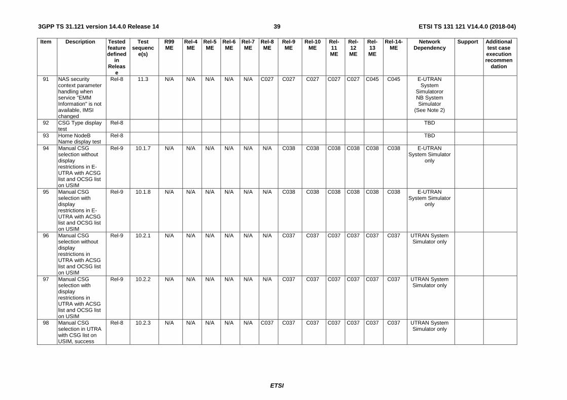
ETSI
ETSI TS 131 121 V14.4.0 (2018-04)393GPP TS 31.121 version 14.4.0 Release 14
Item Description Tested feature defined
in Releas
e
Test sequenc
e(s)
R99 ME
Rel-4 ME
Rel-5 ME
Rel-6 ME
Rel-7 ME
Rel-8 ME
Rel-9 ME
Rel-10 ME
Rel-11 ME
Rel-12 ME
Rel-13 ME
Rel-14-ME
Network Dependency
Support Additional test case execution recommen
dation
91 NAS security context parameter handling when service "EMM Information" is not available, IMSI changed
Rel-8 11.3 N/A N/A N/A N/A N/A C027 C027 C027 C027 C027 C045 C045 E-UTRAN System
Simulatoror NB System Simulator
(See Note 2)
92 CSG Type display test
Rel-8 TBD
93 Home NodeB Name display test
Rel-8 TBD
94 Manual CSG selection without display restrictions in E-UTRA with ACSG list and OCSG list on USIM
Rel-9 10.1.7 N/A N/A N/A N/A N/A N/A C038 C038 C038 C038 C038 C038 E-UTRAN System Simulator
only
95 Manual CSG selection with display restrictions in E-UTRA with ACSG list and OCSG list on USIM
Rel-9 10.1.8 N/A N/A N/A N/A N/A N/A C038 C038 C038 C038 C038 C038 E-UTRAN System Simulator
only
96 Manual CSG selection without display restrictions in UTRA with ACSG list and OCSG list on USIM
Rel-9 10.2.1 N/A N/A N/A N/A N/A N/A C037 C037 C037 C037 C037 C037 UTRAN System Simulator only
97 Manual CSG selection with display restrictions in UTRA with ACSG list and OCSG list on USIM
Rel-9 10.2.2 N/A N/A N/A N/A N/A N/A C037 C037 C037 C037 C037 C037 UTRAN System Simulator only
98 Manual CSG selection in UTRA with CSG list on USIM, success
Rel-8 10.2.3 N/A N/A N/A N/A N/A C037 C037 C037 C037 C037 C037 C037 UTRAN System Simulator only

ETSI
ETSI TS 131 121 V14.4.0 (2018-04)403GPP TS 31.121 version 14.4.0 Release 14
Item Description Tested feature defined
in Releas
e
Test sequenc
e(s)
R99 ME
Rel-4 ME
Rel-5 ME
Rel-6 ME
Rel-7 ME
Rel-8 ME
Rel-9 ME
Rel-10 ME
Rel-11 ME
Rel-12 ME
Rel-13 ME
Rel-14-ME
Network Dependency
Support Additional test case execution recommen
dation
99 EPS NAS Security Context Storage
Rel-8 11.4 N/A N/A N/A N/A N/A C027 C027 C027 C027 C027 C045 C045 E-UTRAN System Simulator
or NB System Simulator
(See Note 2)
100 EFNASCONFIG – NAS signaling priority handling
Rel-10 12.1 N/A N/A N/A N/A N/A N/A N/A N/A N/A N/A N/A NOTE1 No
101 EFNASCONFIG – NMO I Network Mode of Operation I handling
Rel-10 12.2 N/A N/A N/A N/A N/A N/A N/A N/A N/A N/A N/A N/A No
102 Void Rel-10 12.3 N/A N/A N/A N/A N/A N/A N/A N/A N/A N/A N/A N/A No 103 EFNASCONFIG –
Verifying Minimum Periodic Search Timer
Rel-10 12.4 N/A N/A N/A N/A N/A N/A N/A N/A N/A N/A N/A NOTE1 No
104 EFNASCONFIG – Extended access barring handling
Rel-10 12.5 N/A N/A N/A N/A N/A N/A N/A N/A N/A N/A N/A N/A No
105 EFNASCONFIG – Verifying Timer T3245 Behaviour
Rel-10 12.6 N/A N/A N/A N/A N/A N/A N/A N/A N/A C043 C043 C043 UTRAN System Simulator
106 EFNASCONFIG – Override NAS signalling low priority
Rel-11 12.7 N/A N/A N/A N/A N/A N/A N/A N/A N/A N/A C041 C041 UTRAN System Simulator
107 EFNASCONFIG – Override Extended access barring
Rel-11 12.8 N/A N/A N/A N/A N/A N/A N/A N/A N/A N/A C044 C044 UTRAN System Simulator
108 EFNASCONFIG – Fast First Higher Priority PLMN Search
Rel-12 12.9 N/A N/A N/A N/A N/A N/A N/A N/A N/A N/A NOTE1
NOTE1 UTRAN System Simulator
109 EFNASCONFIG – E-UTRA Disabling Allowed for EMM cause #15
Rel-12 12.10 N/A N/A N/A N/A N/A N/A N/A N/A N/A N/A C040 C040 E-UTRAN System Simulator
AND UTRAN System Simulator
110 EFNASCONFIG – SM_RetryWaitTime
Rel-12 12.11 N/A N/A N/A N/A N/A N/A N/A N/A N/A N/A C042 C042 UTRAN System Simulator

ETSI
ETSI TS 131 121 V14.4.0 (2018-04)413GPP TS 31.121 version 14.4.0 Release 14
Item Description Tested feature defined
in Releas
e
Test sequenc
e(s)
R99 ME
Rel-4 ME
Rel-5 ME
Rel-6 ME
Rel-7 ME
Rel-8 ME
Rel-9 ME
Rel-10 ME
Rel-11 ME
Rel-12 ME
Rel-13 ME
Rel-14-ME
Network Dependency
Support Additional test case execution recommen
dation
111 EFNASCONFIG – SM_RetryAtRATChange
Rel-12 12.12 N/A N/A N/A N/A N/A N/A N/A N/A N/A N/A N/A NOTE1 No
112 Correct storage of an SM on the UICC
Rel-13 8.2.7 N/A N/A N/A N/A N/A N/A N/A N/A N/A N/A C046 C046 NB System Simulator only
113 Access Control information handling for NB-IoT
Rel-13 5.2.3 N/A N/A N/A N/A N/A N/A N/A N/A N/A N/A C046 C046 NB System Simulator only
114 Updating the Forbidden PLMN list after receiving non-integrity protected reject message – UTRAN
Rel-13 7.1.7 N/A N/A N/A N/A N/A N/A N/A N/A N/A N/A C048 C048 UMTS System Simulator
AER006
115 Updating the Forbidden PLMN list after receiving non-integrity protected reject message – E-UTRAN
Rel-13 7.1.8 N/A N/A N/A N/A N/A N/A N/A N/A N/A N/A C045 C045 E-UTRAN System Simulator
or NB System Simulator
(See Note 2)
AER006
116 UICC interface in PSM handling for E-UTRAN – No UICC deactivation in PSM
Rel-13 13.1 N/A N/A N/A N/A N/A N/A N/A N/A N/A N/A N/A C051 E-UTRAN System Simulator
or NB System Simulator
(See Note 2)
AER007 AER009
117 UICC interface in PSM handling for E-UTRAN – PSM not accepted by E-USS/NB-SS
Rel-13 13.2 N/A N/A N/A N/A N/A N/A N/A N/A N/A N/A N/A C051 E-UTRAN System Simulator
or NB System Simulator
(See Note 2)
AER007 AER009
118 UICC interface in PSM handling for E-UTRAN – UICC deactivation in PSM
Rel-13 13.3 N/A N/A N/A N/A N/A N/A N/A N/A N/A N/A N/A C051 E-UTRAN System Simulator
or NB System Simulator
(See Note 2)
AER007 AER009

ETSI
ETSI TS 131 121 V14.4.0 (2018-04)423GPP TS 31.121 version 14.4.0 Release 14
Item Description Tested feature defined
in Releas
e
Test sequenc
e(s)
R99 ME
Rel-4 ME
Rel-5 ME
Rel-6 ME
Rel-7 ME
Rel-8 ME
Rel-9 ME
Rel-10 ME
Rel-11 ME
Rel-12 ME
Rel-13 ME
Rel-14-ME
Network Dependency
Support Additional test case execution recommen
dation
119 UICC interface in PSM for E-UTRAN – SUSPEND UICC
Rel-14 13.4 N/A N/A N/A N/A N/A N/A N/A N/A N/A N/A N/A C053 E-UTRAN System Simulator
or NB System Simulator
(See Note 2)
AER007 AER009
120 UICC interface during eDRX for E-UTRAN – eDRX is not supported by the UICC
Rel-13 14.1 N/A N/A N/A N/A N/A N/A N/A N/A N/A N/A N/A C052 E-UTRAN System Simulator
or NB System Simulator
(See Note 2)
AER008 AER010
121 UICC interface during eDRX for E-UTRAN – eDRX is not accepted by E-USS/NB-SS
Rel-13 14.2 N/A N/A N/A N/A N/A N/A N/A N/A N/A N/A N/A C052 E-UTRAN System Simulator
or NB System Simulator
(See Note 2)
AER008 AER010
122 UICC interface during eDRX for E-UTRAN – UICC deactivation during eDRX
Rel-13 14.3 N/A N/A N/A N/A N/A N/A N/A N/A N/A N/A N/A C052 E-UTRAN System Simulator
or NB System Simulator
(See Note 2)
AER008 AER010
123 UICC interface during eDRX for E-UTRAN– SUSPEND UICC
Rel-14 14.4 N/A N/A N/A N/A N/A N/A N/A N/A N/A N/A N/A C054 E-UTRAN System Simulator
or NB System Simulator
(See Note 2)
AER008 AER010
Table B.1: Applicability of tests (continued)
C001 (NOT A.1/3) AND A.1/4 -- (NOT O_UTRAN) AND O_GERAN
C002 A.1/1 AND A.1/3 -- O_CS AND O_UTRAN
C003 A.1/3 AND A.1/4 -- O_UTRAN AND O_GERAN
C004 IF (C001 OR C002) THEN M ELSE N/A -- ((NOT O_UTRAN) AND O_GERAN) OR (O_CS AND O_UTRAN)
C005 IF A.1/2 THEN M ELSE N/A -- O_PIN2_ENTRY_FEAT
C006 IF (C001 OR C002) AND A.1/5 AND A.1/18 THEN M ELSE N/A
-- (((NOT O_UTRAN) AND O_GERAN) OR (O_CS AND O_UTRAN) AND O_FDN AND O_Speech_Calls

ETSI
ETSI TS 131 121 V14.4.0 (2018-04)433GPP TS 31.121 version 14.4.0 Release 14
C007 IF (C001 OR C002) AND A.1/6 AND A.1/18 THEN M ELSE N/A
-- (((NOT O_UTRAN) AND O_GERAN) OR (O_CS AND O_UTRAN)) AND O_AoCC AND O_Speech_Calls
C008 IF (C001 OR C002) AND A.1/6 AND A.1/18 THEN O.1 ELSE N/A
-- (((NOT O_UTRAN) AND O_GERAN) OR (O_CS AND O_UTRAN)) AND O_AoCC AND O_Speech_Calls
C009 IF C003 THEN M ELSE N/A -- O_UTRAN AND O_GERAN
C010 IF (C001 OR (A.1/3 AND (!A.1/4)) OR (C003 AND (!A.1/7))) THEN M ELSE N/A
-- (((NOT O_UTRAN) AND O_GERAN) OR (O_UTRAN AND (NOT O_GERAN)) OR (O_UTRAN AND O_GERAN AND (NOT O_HPLMNwACT)))
C011 IF C003 AND A.1/7 THEN M ELSE O -- O_UTRAN AND O_GERAN AND O_HPLMNwACT
C012 IF A.1/8 THEN M ELSE N/A -- O_Local_PB
C013 IF A.1/9 THEN M ELSE N/A -- O_Global_PB
C014 IF A.1/8 AND A.1/9 THEN M ELSE N/A -- O_Local_PB AND O_Global_PB
C015 IF A.1/10 AND (A.1/3 OR A.1/4) THEN M ELSE N/A
-- O_Store_Received_SMS AND (O_UTRAN OR O_GERAN)
C016 IF A.1/11 AND A.1/12 AND A.1/13 THEN M ELSE N/A
-- O_MMS AND O_MMS_USIM_DATA AND
C017 IF A.1/11 AND A.1/13 THEN M ELSE N/A
-- O_MMS AND O_NO_USER_MMS_CONF_SELEC
C018 IF A.1/11 AND A.1/14 THEN M ELSE N/A
-- O_MMS AND O_MMS_NOTIF_STORAGE
C019 IF A.1/15 AND (A.1/3 OR A.1/4) THEN M ELSE N/A
-- O_ACL AND (O_UTRAN OR O_GERAN)
C020 IF (NOT A.1/15) AND (A.1/3 OR A.1/4)M ELSE N/A
-- (NOT O_ACL) AND (O_UTRAN OR O_GERAN)
C021 IF A.1/16 THEN M ELSE N/A -- O_SDN
C022 IF A.1/17 THEN M ELSE N/A -- O_EFPLMNwACT_numerical entry
C023 IF A.1/18 THEN M ELSE N/A -- O_Speech_Calls
C024 IF C004 AND A.1/18 THEN M ELSE N/A -- (((NOT O_UTRAN) AND O_GERAN) OR (O_CS AND O_UTRAN)) AND O_Speech_Calls
C025 IF A.1/19 THEN “Expected Sequence A” M ELSE “Expected Sequence B” M
-- O_PIN_MMI_Strings

ETSI
ETSI TS 131 121 V14.4.0 (2018-04)443GPP TS 31.121 version 14.4.0 Release 14
C026 IF A1/2 AND A.1/19 THEN “Expected Sequence A” M
-- (O_PIN2_ENTRY_FEAT AND O_PIN_MMI_Strings) OR O_PIN2_ENTRY_FEAT
C027 IF (A.1/20 OR A.1/21) THEN M ELSE N/A
-- pc_eFDD OR pc_eTDD
C028 IF (A.1/20 OR A.1/21) AND A.1/22 THEN M ELSE N/A
-- (pc_eFDD OR pc_eTDD) AND pc_Allowed_CSG_list
C029 Void
C030 Void
C031 IF (A.1/10 AND A.1/23 AND (A.1/20 OR A.1/21)) THEN M ELSE N/A
-- O_Store_Received_SMS AND pc_SM-over-IP receiver AND (pc_eFDD OR pc_eTDD)
C032 IF (A.1/10 AND AND A.1/23 AND A.1/3) THEN M ELSE N/A
-- O_Store_Received_SMS AND pc_SM-over-IP receiver AND (O_UTRAN)
C033 IF (A.1/24) THEN M ELSE N/A -- pc_USIM_EF_SMS_reading_support_if_USIM_ISIM both present
C034 IF (A.1/25) THEN M ELSE N/A -- pc_ISIM_EF_SMS_reading_support_if_USIM_ISIM both present
C035 IF (A.1/10 AND NOT A.1/26 AND (A.1/3 OR A.1/4)) THEN M ELSE N/A
-- O_Store_Received_SMS AND NOT O_LARGE_SMS_STORAGE AND (O_UTRAN OR O_GERAN)
C036 IF (A.1/20 OR A.1/21) AND A.1/27 THEN M ELSE N/A
-- pc_eFDD OR pc_eTDD AND pc_Multiple_PDN
C037 IF (A.1/3) AND A.1/28 AND A.1/29 AND NOT ((A.1/20 OR A.1/21) AND A.1/22) THEN M ELSE N/A
-- O_UTRAN AND pc_CSG AND pc_manual_CSG_selection AND NOT ((pc_eFDD OR pc_eTDD) AND pc_Allowed_CSG_list)
C038 IF (A.1/20 OR A.1/21) AND A.1/22 AND A.1/29 THEN M ELSE N/A
-- (pc_eFDD OR pc_eTDD) AND pc_Allowed_CSG_list AND pc_manual_CSG_selection
C039 IF A.1/1 AND A.1/30 THEN M ELSE N/A -- O_CS AND O_PS
C040 IF A.1/33 THEN M ELSE N/A -- O_EUTRA_Disabling_EMM_cause#15
C041 IF A.1/3 AND A.1/34 THEN M ELSE N/A -- O_UTRAN AND O_Override_NAS_signalling_low_priority
C042 IF A.1/3 AND A.1/30 THEN M ELSE N/A -- O_UTRAN AND O_PS
C043 IF A.1/3 AND A.1/35 THEN M ELSE N/A -- O_UTRAN AND O_T3245
C044 IF A.1/3 AND A.1/36 THEN M ELSE N/A -- O_UTRAN AND O_Override_EAB

ETSI
ETSI TS 131 121 V14.4.0 (2018-04)453GPP TS 31.121 version 14.4.0 Release 14
C045 IF A.1/20 OR A.1/21 OR A.1/37 THEN M ELSE N/A
-- pc_eFDD OR pc_eTDD OR pc_NB
C046 IF A.1/37 THEN M ELSE N/A -- pc_NB
C047 IF (A.1/3 OR (A.1/4 AND NOT A.1/38)) THEN M ELSE N/A
-- O_UTRAN OR (O_GERAN AND NOT O_PLMN_specific_PS_attempt_counters)
C048 IF A.1/3 THEN M ELSE N/A -- O_UTRAN
C049 IF A.1/3 OR A.1/4 THEM M ELSE N/A -- O_UTRAN OR O_GERAN
C050 IF A.1/15 AND (A.1/20 OR A.1/21) THEN M ELSE N/A
-- O_ACL AND (pc_eFDD OR pc_eTDD)
C051 ..IF (A.1/20 OR A.1/21 OR A.1/37) AND A.1/39 THEN M ELSE N/A
-- (pc_eFDD OR pc_eTDD OR pc_NB) AND O_PSM_DEAC_UICC
C052 IF (A.1/20 OR A.1/21 OR A.1/37) AND A.1/40 THEN M ELSE N/A
-- (pc_eFDD OR pc_eTDD OR pc_NB) AND O_eDRX_DEAC_UICC
C053 IF (A.1/20 OR A.1/21 OR A.1/37) AND A.1/41 THEN M ELSE N/A
-- (pc_eFDD OR pc_eTDD OR pc_NB) AND O_PSM_ SUSPEND_UICC
C054 IF (A.1/20 OR A.1/21 OR A.1/37) AND A.1/42 THEN M ELSE N/A
-- (pc_eFDD OR pc_eTDD OR pc_NB) AND O_eDRX_ SUSPEND_UICC
O.1 IF C002 THEN "Expected Sequence A" M ELSE IF C001 THEN "Expected Sequence B" M
AER001 IF ((A.1/20 OR A.1/21) AND ((A.1/3 OR A.1/4) AND (NOT A.1/18))) THEN R ELSE A
-- ((pc_eFDD OR pc_eTDD) AND ((O_UTRAN OR O_GERAN) AND (NOT O_Speech_Calls)))
AER002 IF ((A.1/20 OR A.1/21) AND ((A.1/3 OR A.1/4) THEN R ELSE A
-- (NOT O_UTRAN) AND ((O_GERAN AND (NOT O_CS))
AER003 IF (test 8.2.3 has been PASSED) THEN R ELSE A
AER004 IF (test 8.2.5 has been PASSED) THEN R ELSE A
AER005 IF ((NOT A.1/3) AND ((A.1/4) AND (NOT A.1/1)) THEN R ELSE A
-- (NOT O_UTRAN) AND ((O_GERAN AND (NOT O_CS))
AER006 If A.1/38 is supported set the implementation specific counter to small value to reduce the test execution time.

ETSI
ETSI TS 131 121 V14.4.0 (2018-04)463GPP TS 31.121 version 14.4.0 Release 14
AER007 If A.1/39 is supported, in addition to the test case initial conditions, any specific information or particular UE configurations required to ensure that the UE performs UICC deactivation in PSM shall be provided by the UE manufacturer.
AER008 If A.1/40 is supported, in addition to the test case initial conditions, any specific information or particular UE configurations required to ensure that the UE performs UICC deactivation in eDRX shall be provided by the UE manufacturer
AER009 The value of timers T3324 (T3324_V) and T3412 (T3412_V) shall be provided by the UE manufacturer and shall be set to a value suitable for executing the test cases.
AER010 The value of eDRX (eDRX_V) and PTW (PTW_V) parameters shall be provided by the UE manufacturer and shall be set to a value suitable for executing the test cases.
NOTE 1: Definition of applicability for this test case is FFS. NOTE 2: For Rel-13, if the UE supports NB-IoT, this test case shall be verified by accessing the NB System Simulator (NB-SS).

ETSI
ETSI TS 131 121 V14.4.0 (2018-04)473GPP TS 31.121 version 14.4.0 Release 14
4 Default Values All tests defined in the subsequent clauses apply to Terminals using card types specified in ETSI TS 102 221 [5], unless otherwise stated.
The following sequence of tests confirms:
a) the correct interpretation of data read from the USIM (Universal Subscriber Identification Module) by the Terminal;
b) the correct writing of data to the USIM by the Terminal;
c) the initiation of appropriate procedures by the Terminal;
d) High level protocols.
All tests apply to the USIM application on the UICC.
A USIM simulator will be required as part of the USS. Alternatively, to perform the logical tests, USIMs programmed with specific data may be used. The USIM data is not defined within the initial conditions of the tests unless it differs from the default values defined below.
4.1 Definition of default values for USIM-Terminal interface testing (Default UICC)
A USIM containing the following default values is used for all tests of this present document unless otherwise stated.
The service "Non-Access Stratum configuration by USIM" shall not be available unless otherwise specified.
For each data item, the logical default values and the coding within the elementary files (EF) of the USIM follow.
NOTE 1: Bx represents byte x of the coding.
NOTE 2: Unless otherwise defined, the coding values are hexadecimal.
4.1.1 Values of the EF's (Default UICC)
4.1.1.1 EFIMSI (IMSI)
Logically: 2460813579
Coding: B1 B2 B3 B4 B5 B6 B7 B8 B9 Hex 06 21 64 80 31 75 F9 FF FF
4.1.1.2 EFAD (Administrative Data)
Logically: Normal operation OFM to be deactivated by the Terminal MNC: 3 digit
Coding: B1 B2 B3 B4 Hex 00 00 00 03
4.1.1.3 EFLOCI (Location Information)
Logically: LAI-MCC: 246 LAI-MNC: 081
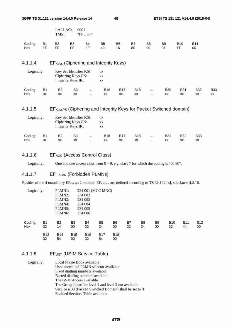
ETSI
ETSI TS 131 121 V14.4.0 (2018-04)483GPP TS 31.121 version 14.4.0 Release 14
LAI-LAC: 0001 TMSI: "FF .. FF"
Coding: B1 B2 B3 B4 B5 B6 B7 B8 B9 B10 B11 Hex FF FF FF FF 42 16 80 00 01 FF 00
4.1.1.4 EFKeys (Ciphering and Integrity Keys)
Logically: Key Set Identifier KSI: 0x Ciphering Keys CK: xx Integrity Keys IK: xx
Coding: B1 B2 B3 … B16 B17 B18 … B30 B31 B32 B33 Hex 0x xx xx … xx xx xx … xx xx xx xx
4.1.1.5 EFKeysPS (Ciphering and Integrity Keys for Packet Switched domain)
Logically: Key Set Identifier KSI: 0x Ciphering Keys CK: xx Integrity Keys IK: xx
Coding: B1 B2 B3 … B16 B17 B18 … B31 B32 B33 Hex 0x xx xx … xx xx xx … xx xx xx
4.1.1.6 EFACC (Access Control Class)
Logically: One and one access class from 0 – 9, e.g. class 7 for which the coding is "00 80".
4.1.1.7 EFFPLMN (Forbidden PLMNs)
Besides of the 4 mandatory EFFPLMN 2 optional EFFPLMN are defined according to TS 31.102 [4], subclause 4.2.16.
Logically: PLMN1: 234 001 (MCC MNC) PLMN2: 234 002 PLMN3: 234 003 PLMN4: 234 004 PLMN5: 234 005 PLMN6: 234 006
Coding: B1 B2 B3 B4 B5 B6 B7 B8 B9 B10 B11 B12 Hex 32 14 00 32 24 00 32 34 00 32 44 00 B13 B14 B15 B16 B17 B18 32 54 00 32 64 00
4.1.1.8 EFUST (USIM Service Table)
Logically: Local Phone Book available User controlled PLMN selector available Fixed dialling numbers available Barred dialling numbers available The GSM Access available The Group Identifier level 1 and level 2 not available Service n 33 (Packed Switched Domain) shall be set to '1'
Enabled Services Table available

ETSI
ETSI TS 131 121 V14.4.0 (2018-04)493GPP TS 31.121 version 14.4.0 Release 14
Coding: B1 B2 B3 B4 B5 binary xx1x xx11 xxxx xxxx xxxx 1x00 xxxx x1xx xxxx xx11
The coding of EFUST shall conform with the capabilities of the USIM used.
4.1.1.9 EFEST (Enable Service Table)
Logically: Fixed Dialling Numbers (FDN) disabled. Barred Dialling Numbers (BDN) disabled. APN Control list (ACL) disabled
Coding: B1 binary 0000 0000
The coding of EFEST shall conform with the capabilities of the USIM, unused Bits are set to '0'.
4.1.1.10 EFADN (Abbreviated Dialling Number)
Logically: At least 10 records, each non empty record unique.
Record 1: Length of alpha identifier: 32 characters; Alpha identifier: "ABCDEFGHIJKLMNOPQRSTUVWXYZABCDEF"; Length of BCD number: "03"; TON and NPI: Telephony and Unknown; Dialled number: 123; CCI: None; Ext1: None.
Record 1:
Coding: B1 B2 B3 … B32 B33 B34 B35 B36 B37 B38 B39 … B46 Hex 41 42 43 … 46 03 81 21 F3 FF FF FF … FF
4.1.1.11 EFPLMNwACT (User Controlled PLMN Selector with Access Technology)
Besides of the 8 mandatory PLMNwACT entries 4 optional PLMNwACT entries are defined according to TS 31.102 [4], subclause 4.2.5. The Radio Access Technology identifier for the first two PLMN (1st PLMN and 2nd PLMN) are set to both UTRAN and GSM, all other PLMN to UTRAN only.
Logically: 1st PLMN: 244 081 (MCC MNC) 1st ACT: UTRAN 2nd PLMN: 244 081 2nd ACT: GSM 3rd PLMN: 244 082 3rd ACT: UTRAN 4th PLMN: 244 082 4th ACT: GSM 5th PLMN: 244 003 5th ACT: UTRAN 6th PLMN: 244 004 6th ACT: UTRAN 7th PLMN: 244 005 7th ACT: UTRAN 8th PLMN: 244 006 8th ACT: UTRAN 9th PLMN: 244 007 9th ACT: UTRAN 10th PLMN: 244 008

ETSI
ETSI TS 131 121 V14.4.0 (2018-04)503GPP TS 31.121 version 14.4.0 Release 14
10th ACT: UTRAN 11th PLMN: 244 009 11th ACT: UTRAN 12th PLMN: 244 010 12th ACT: UTRAN
Coding: B1 B2 B3 B4 B5 B6 B7 B8 B9 B10 B11 B12 B13 B14 B15 Hex 42 14 80 80 00 42 14 80 00 80 42 24 80 80 00 B16 B17 B18 B19 B20 B21 B22 B23 B24 B25 B26 B27 B28 B29 B30 42 24 80 00 80 42 34 00 80 00 42 44 00 80 00 B31 B32 B33 B34 B35 B36 B37 B38 B39 B40 B41 B42 B43 B44 B45 42 54 00 80 00 42 64 00 80 00 42 74 00 80 00 B46 B47 B48 B49 B50 B51 B52 B53 B54 B55 B56 B57 B58 B59 B60 42 84 00 80 00 42 94 00 80 00 42 04 10 80 00
4.1.1.12 EFOPLMNwACT (Operator Controlled PLMN Selector with Access Technology)
The Radio Access Technology identifier for the first PLMN is set to both UTRAN and GSM, the other remaining PLMNs to UTRAN only.
Logically: 1st PLMN: 254 001 (MCC MNC) 1st ACT: UTRAN 2nd PLMN: 254 001 2nd ACT: GSM 3rd PLMN: 254 002 3rd ACT: UTRAN 4th PLMN: 254 003 4th ACT: UTRAN 5th PLMN: 254 004 5th ACT: UTRAN 6th PLMN: 254 005 6th ACT: UTRAN 7th PLMN: 254 006 7th ACT: UTRAN 8th PLMN: 254 007 8th ACT: UTRAN
Coding: B01 B02 B03 B04 B05 B06 B07 B08 B09 B10 Hex 52 14 00 80 00 52 14 00 00 80 B11 B12 B13 B14 B15 B16 B17 B18 B19 B20 52 24 00 80 00 52 34 00 80 00 B21 B22 B23 B24 B25 B26 B27 B28 B29 B30 52 44 00 80 00 52 54 00 80 00 B31 B32 B33 B34 B35 B36 B37 B38 B39 B40 52 64 00 80 00 52 74 00 80 00
4.1.1.13 Void
4.1.1.14 PIN
Key reference: 01
Logically: 2468
Coding: B1 B2 B3 B4 B5 B6 B7 B8 Hex 32 34 36 38 FF FF FF FF

ETSI
ETSI TS 131 121 V14.4.0 (2018-04)513GPP TS 31.121 version 14.4.0 Release 14
4.1.1.15 PIN2
Key reference: 81
Logically: 3579
Coding: B1 B2 B3 B4 B5 B6 B7 B8 Hex 33 35 37 39 FF FF FF FF
4.1.1.16 Unblock PIN
Key reference: 01
Logically: 13243546
Coding: B1 B2 B3 B4 B5 B6 B7 B8 Hex 31 33 32 34 33 35 34 36
4.1.1.17 Unblock PIN2
Key reference: 81
Logically: 08978675
Coding: B1 B2 B3 B4 B5 B6 B7 B8 Hex 30 38 39 37 38 36 37 35
4.1.1.18 Other Values of the USIM
All other values of Efs provided by the USIM shall be set to the default values defined in the annex E of TS 31.102 [4]. Some Efs (like the GSM Access files) may necessary for some tests and apply only to those test cases.
4.1.1.19 EFPSLOCI (Packet Switch Location Information)
Logically: RAI-MCC: 246 RAI-MNC: 081 RAI-LAC: 0001 RAI-RAC: 05 P-TMSI: "FF….FF" P-TMSI signature value: "FF…FF"
Coding: B1 B2 B3 B4 B5 B6 B7 B8 B9 B10 B11 Hex FF FF FF FF FF FF FF 42 16 80 00 Coding: B12 B13 B14 Hex 01 05 00
4.1.1.20 Universal PIN
Key reference: 11
Logically: 2839
Coding: B1 B2 B3 B4 B5 B6 B7 B8 Hex 32 38 33 39 FF FF FF FF
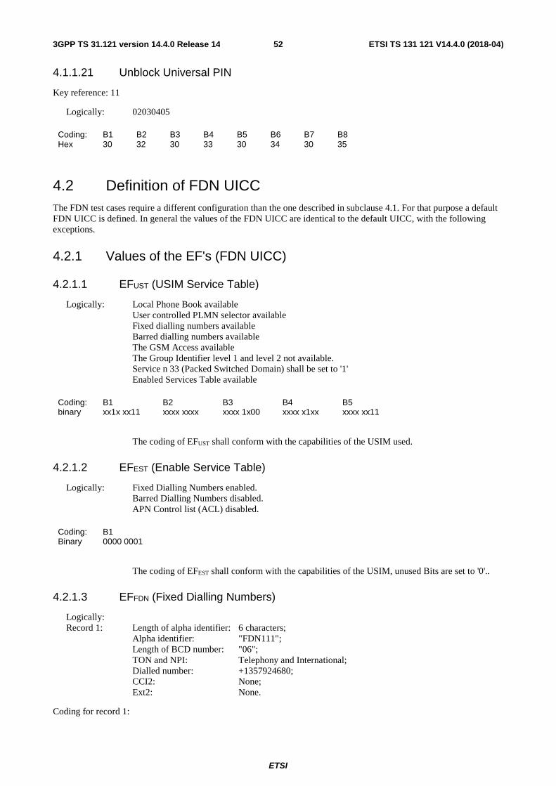
ETSI
ETSI TS 131 121 V14.4.0 (2018-04)523GPP TS 31.121 version 14.4.0 Release 14
4.1.1.21 Unblock Universal PIN
Key reference: 11
Logically: 02030405
Coding: B1 B2 B3 B4 B5 B6 B7 B8 Hex 30 32 30 33 30 34 30 35
4.2 Definition of FDN UICC The FDN test cases require a different configuration than the one described in subclause 4.1. For that purpose a default FDN UICC is defined. In general the values of the FDN UICC are identical to the default UICC, with the following exceptions.
4.2.1 Values of the EF's (FDN UICC)
4.2.1.1 EFUST (USIM Service Table)
Logically: Local Phone Book available User controlled PLMN selector available Fixed dialling numbers available Barred dialling numbers available The GSM Access available The Group Identifier level 1 and level 2 not available. Service n 33 (Packed Switched Domain) shall be set to '1'
Enabled Services Table available
Coding: B1 B2 B3 B4 B5 binary xx1x xx11 xxxx xxxx xxxx 1x00 xxxx x1xx xxxx xx11
The coding of EFUST shall conform with the capabilities of the USIM used.
4.2.1.2 EFEST (Enable Service Table)
Logically: Fixed Dialling Numbers enabled. Barred Dialling Numbers disabled. APN Control list (ACL) disabled.
Coding: B1 Binary 0000 0001
The coding of EFEST shall conform with the capabilities of the USIM, unused Bits are set to '0'..
4.2.1.3 EFFDN (Fixed Dialling Numbers)
Logically: Record 1: Length of alpha identifier: 6 characters; Alpha identifier: "FDN111"; Length of BCD number: "06"; TON and NPI: Telephony and International; Dialled number: +1357924680; CCI2: None; Ext2: None.
Coding for record 1:
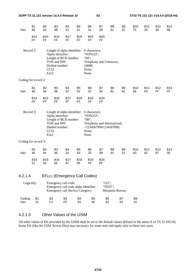
ETSI
ETSI TS 131 121 V14.4.0 (2018-04)533GPP TS 31.121 version 14.4.0 Release 14
B1 B2 B3 B4 B5 B6 B7 B8 B9 B10 B11 B12 B13 Hex 46 44 4E 31 31 31 06 91 31 75 29 64 08 B14 B15 B16 B17 B18 B19 B20 FF FF FF FF FF FF FF
Record 2: Length of alpha identifier: 6 characters; Alpha identifier: "FDN222"; Length of BCD number: "04"; TON and NPI: Telephony and Unknown; Dialled number: 24680; CCI2: None; Ext2: None.
Coding for record 2:
B1 B2 B3 B4 B5 B6 B7 B8 B9 B10 B11 B12 B13 Hex 46 44 4E 32 32 32 04 81 42 86 F0 FF FF B14 B15 B16 B17 B18 B19 B20 FF FF FF FF FF FF FF
Record 3: Length of alpha identifier: 6 characters; Alpha identifier: "FDN333"; Length of BCD number: "0B"; TON and NPI: Telephony and International; Dialled number: +12345678901234567890; CCI2: None; Ext2: None.
Coding for record 3:
B1 B2 B3 B4 B5 B6 B7 B8 B9 B10 B11 B12 B13 Hex 46 44 4E 33 33 33 0B 91 21 43 65 87 09 B14 B15 B16 B17 B18 B19 B20 21 43 65 87 09 FF FF
4.2.1.4 EFECC (Emergency Call Codes)
Logically: Emergency call code: "122"; Emergency call code alpha identifier: "TEST"; Emergency call Service Category: Mountain Rescue.
Coding: B1 B2 B3 B4 B5 B6 B7 B8 Hex 21 F2 FF 54 45 53 54 10
4.2.1.5 Other Values of the USIM
All other values of Efs provided by the USIM shall be set to the default values defined in the annex E of TS 31.102 [4]. Some Efs (like the GSM Access files) may necessary for some tests and apply only to those test cases.

ETSI
ETSI TS 131 121 V14.4.0 (2018-04)543GPP TS 31.121 version 14.4.0 Release 14
4.3 Void
4.4 Definition of E-UTRAN/EPC UICC The E-UTRAN/EPC test cases require a different configuration than the one described in subclause 4.1. For that purpose a default E-UTRAN/EPC UICC is defined. In general the values of the E-UTRAN/EPC UICC are identical to the default UICC, with the following exceptions:
4.4.1 EFUST (USIM Service Table)
Logically: Local Phone Book available User controlled PLMN selector available Fixed dialling numbers available Barred dialling numbers available The GSM Access available The Group Identifier level 1 and level 2 not available Service n 33 (Packed Switched Domain) shall be set to '1'
Enabled Services Table available EPS Mobility Management Information available Allowed CSG Lists and corresponding indications
Byte: B1 B2 B3 B4 B5 B6 B7 B8 Binary: xx1x xx11 xxxx xxxx xxxx 1x00 xxxx x1xx xxxx xx11 xxxx xxxx xxxx xxxx xxxx xxxx B9 B10 B11 xxxx xxxx xxxx xxxx xx11 xxxx
The coding of EFUST shall conform with the capabilities of the USIM used.
4.4.2 EFEPSLOCI (EPS Information)
Logically: GUTI: 24608100010266431122 Last visited registered TAI: 246/081/0001 EPS update status: not updated
Byte: B1 B2 B3 B4 B5 B6 B7 B8 B9 B10 B11 Hex: 0B F6 42 16 80 00 01 02 66 43 11 B12 B13 B14 B15 B16 B17 B18 22 42 16 80 00 01 01
4.4.3 EFPLMNwACT (User Controlled PLMN Selector with Access Technology)
Besides of the 8 mandatory PLMNwACT entries 4 optional PLMNwACT entries are defined according to TS 31.102 [4], subclause 4.2.5. The Radio Access Technology identifiers are set either to E-UTRAN only, UTRAN only or GSM only.
Logically: 1st PLMN: 244 081 (MCC MNC) 1st ACT: E-UTRAN 2nd PLMN: 244 081 2nd ACT: GSM 3rd PLMN: 244 083 3rd ACT: E-UTRAN 4th PLMN: 244 082 4th ACT: GSM

ETSI
ETSI TS 131 121 V14.4.0 (2018-04)553GPP TS 31.121 version 14.4.0 Release 14
5th PLMN: 244 003 5th ACT: E-UTRAN 6th PLMN: 244 004 6th ACT: UTRAN 7th PLMN: 244 005 7th ACT: UTRAN 8th PLMN: 244 081 8th ACT: UTRAN 9th PLMN: 244 007 9th ACT: UTRAN 10th PLMN: 244 008 10th ACT: E-UTRAN 11th PLMN: 244 009 11th ACT: UTRAN 12th PLMN: 244 010 12th ACT: E-UTRAN
Coding: B1 B2 B3 B4 B5 B6 B7 B8 B9 B10 B11 B12 B13 B14 B15 Hex 42 14 80 40 00 42 14 80 00 80 42 34 80 40 00 B16 B17 B18 B19 B20 B21 B22 B23 B24 B25 B26 B27 B28 B29 B30 42 24 80 00 80 42 34 00 40 00 42 44 00 80 00 B31 B32 B33 B34 B35 B36 B37 B38 B39 B40 B41 B42 B43 B44 B45 42 54 00 80 00 42 14 80 80 00 42 74 00 80 00 B46 B47 B48 B49 B50 B51 B52 B53 B54 B55 B56 B57 B58 B59 B60 42 84 00 40 00 42 94 00 80 00 42 04 10 40 00
4.4.4 EFOPLMNwACT (Operator Controlled PLMN Selector with Access Technology)
The Radio Access Technology identifier for the first PLMN is set to both UTRAN and GSM, the other remaining PLMNs to UTRAN only or E-UTRAN only.
Logically: 1st PLMN: 254 001 (MCC MNC) 1st ACT: E-UTRAN 2nd PLMN: 254 001 2nd ACT: GSM 3rd PLMN: 254 002 3rd ACT: E-UTRAN 4th PLMN: 254 003 4th ACT: E-UTRAN 5th PLMN: 254 004 5th ACT: UTRAN 6th PLMN: 254 005 6th ACT: UTRAN 7th PLMN: 254 006 7th ACT: UTRAN 8th PLMN: 254 007 8th ACT: UTRAN
Coding: B01 B02 B03 B04 B05 B06 B07 B08 B09 B10 Hex 52 14 00 40 00 52 14 00 00 80 B11 B12 B13 B14 B15 B16 B17 B18 B19 B20 52 24 00 40 00 52 34 00 40 00 B21 B22 B23 B24 B25 B26 B27 B28 B29 B30 52 44 00 80 00 52 54 00 80 00 B31 B32 B33 B34 B35 B36 B37 B38 B39 B40 52 64 00 80 00 52 74 00 80 00

ETSI
ETSI TS 131 121 V14.4.0 (2018-04)563GPP TS 31.121 version 14.4.0 Release 14
4.4.5 EFACSGL (Allowed CSG Lists)
For testing 2 CSG lists are defined and stored together in record one.
Logically:
1st CSG list
PLMN: 246 081 (MCC MNC) 1st CSG list 1st CSG Type indication 02 1st CSG list 1st CSG HNB Name indication 02 1st CSG list 1st CSG CSG ID: 02 (27bit) 1st CSG list 2nd CSG Type indication 03 1st CSG list 2nd CSG HNB Name indication 03 1st CSG list 2nd CSG CSG ID: 03 (27bit)
2nd CSG list
PLMN: 244 081 (MCC MNC) 2nd CSG list 1st CSG Type indication 08 2nd CSG list 1st CSG HNB Name indication 08 2nd CSG list 1st CSG CSG ID: 08 (27bit)
Byte: B01 B02 B03 B04 B05 B06 B07 B08 B09 B10 Coding: A0 15 80 03 42 16 80 81 06 02 B11 B12 B13 B14 B15 B16 B17 B18 B19 B20 02 00 00 00 5F 81 06 03 03 00 B21 B22 B23 B24 B25 B26 B27 B28 B29 B30 00 00 7F A0 0D 80 03 42 14 80 B31 B32 B33 B34 B35 B36 B37 B38 B39 .. 81 06 08 08 00 00 01 1F FF FF Bxx FF
All other records are empty.
4.4.6 EFCSGT (CSG Type)
Record 1:
Logically: Group ONE
Byte: B01 B02 B03 B04 B05 B06 B07 B08 B09 B10 Coding: 89 13 80 00 47 00 72 00 6F 00 B11 B12 B13 B14 B15 B16 B17 B18 B19 B20 75 00 70 00 20 00 4F 00 4E 00 B21 B22 B23 B24 B25 B26 B27 B28 B29 B30 45 FF FF FF FF FF FF FF FF FF
Record 2:
Logically: Group TWO

ETSI
ETSI TS 131 121 V14.4.0 (2018-04)573GPP TS 31.121 version 14.4.0 Release 14
Byte: B01 B02 B03 B04 B05 B06 B07 B08 B09 B10 Coding: 89 13 80 00 47 00 72 00 6F 00 B11 B12 B13 B14 B15 B16 B17 B18 B19 B20 75 00 70 00 20 00 54 00 57 00 B21 B22 B23 B24 B25 B26 B27 B28 B29 B30 4F FF FF FF FF FF FF FF FF FF
Record 3:
Logically: Group THREE
Byte: B01 B02 B03 B04 B05 B06 B07 B08 B09 B10 Coding: 89 17 80 00 47 00 72 00 6F 00 B11 B12 B13 B14 B15 B16 B17 B18 B19 B20 75 00 70 00 20 00 54 00 48 00 B21 B22 B23 B24 B25 B26 B27 B28 B29 B30 52 00 45 00 45 FF FF FF FF FF
Record 4:
Logically: Group FOUR
Byte: B01 B02 B03 B04 B05 B06 B07 B08 B09 B10 Coding: 89 15 80 00 47 00 72 00 6F 00 B11 B12 B13 B14 B15 B16 B17 B18 B19 B20 75 00 70 00 20 00 46 00 4F 00 B21 B22 B23 B24 B25 B26 B27 B28 B29 B30 55 00 52 FF FF FF FF FF FF FF
Record 5:
Logically: Group FIVE
Byte: B01 B02 B03 B04 B05 B06 B07 B08 B09 B10 Coding: 89 15 80 00 47 00 72 00 6F 00 B11 B12 B13 B14 B15 B16 B17 B18 B19 B20 75 00 70 00 20 00 46 00 49 00 B21 B22 B23 B24 B25 B26 B27 B28 B29 B30 56 00 45 FF FF FF FF FF FF FF
Record 6:
Logically: Group SIX
Byte: B01 B02 B03 B04 B05 B06 B07 B08 B09 B10 Coding: 89 13 80 00 47 00 72 00 6F 00 B11 B12 B13 B14 B15 B16 B17 B18 B19 B20 75 00 70 00 20 00 53 00 49 00 B21 B22 B23 B24 B25 B26 B27 B28 B29 B30 58 FF FF FF FF FF FF FF FF FF
Record 7:
Logically: Group SEVEN
Byte: B01 B02 B03 B04 B05 B06 B07 B08 B09 B10 Coding: 89 17 80 00 47 00 72 00 6F 00 B11 B12 B13 B14 B15 B16 B17 B18 B19 B20 75 00 70 00 20 00 53 00 45 00 B21 B22 B23 B24 B25 B26 B27 B28 B29 B30 56 00 45 00 4E FF FF FF FF FF

ETSI
ETSI TS 131 121 V14.4.0 (2018-04)583GPP TS 31.121 version 14.4.0 Release 14
Record 8:
Logically: Group EIGHT
Byte: B01 B02 B03 B04 B05 B06 B07 B08 B09 B10 Coding: 89 17 80 00 47 00 72 00 6F 00 B11 B12 B13 B14 B15 B16 B17 B18 B19 B20 75 00 70 00 20 00 45 00 49 00 B21 B22 B23 B24 B25 B26 B27 B28 B29 B30 47 00 48 00 54 FF FF FF FF FF
4.4.7 EFHNBN (Home (e)NodeB Name)
Record 1:
Logically: Home ONE
Byte: B01 B02 B03 B04 B05 B06 B07 B08 B09 B10 Coding: 80 11 80 00 48 00 6F 00 6D 00 B11 B12 B13 B14 B15 B16 B17 B18 B19 B20 65 00 20 00 4F 00 4E 00 45 FF B21 B22 B23 B24 B25 B26 B27 B28 B29 B30 FF FF FF FF FF FF FF FF FF FF
Record 2:
Logically: Home TWO
Byte: B01 B02 B03 B04 B05 B06 B07 B08 B09 B10 Coding: 80 11 80 00 48 00 6F 00 6D 00 B11 B12 B13 B14 B15 B16 B17 B18 B19 B20 65 00 20 00 54 00 57 00 4F FF B21 B22 B23 B24 B25 B26 B27 B28 B29 B30 FF FF FF FF FF FF FF FF FF FF
Record 3:
Logically: Home THREE
Byte: B01 B02 B03 B04 B05 B06 B07 B08 B09 B10 Coding: 80 15 80 00 48 00 6F 00 6D 00 B11 B12 B13 B14 B15 B16 B17 B18 B19 B20 65 00 20 00 54 00 48 00 52 00 B21 B22 B23 B24 B25 B26 B27 B28 B29 B30 45 00 45 FF FF FF FF FF FF FF
Record 4:
Logically: Home FOUR
Byte: B01 B02 B03 B04 B05 B06 B07 B08 B09 B10 Coding: 80 13 80 00 48 00 6F 00 6D 00 B11 B12 B13 B14 B15 B16 B17 B18 B19 B20 65 00 20 00 46 00 4F 00 55 00 B21 B22 B23 B24 B25 B26 B27 B28 B29 B30 52 FF FF FF FF FF FF FF FF FF
Record 5:
Logically: Home FIVE

ETSI
ETSI TS 131 121 V14.4.0 (2018-04)593GPP TS 31.121 version 14.4.0 Release 14
Byte: B01 B02 B03 B04 B05 B06 B07 B08 B09 B10 Coding: 80 13 80 00 48 00 6F 00 6D 00 B11 B12 B13 B14 B15 B16 B17 B18 B19 B20 65 00 20 00 46 00 49 00 56 00 B21 B22 B23 B24 B25 B26 B27 B28 B29 B30 45 FF FF FF FF FF FF FF FF FF
Record 6:
Logically: Home SIX
Byte: B01 B02 B03 B04 B05 B06 B07 B08 B09 B10 Coding: 80 11 80 00 48 00 6F 00 6D 00 B11 B12 B13 B14 B15 B16 B17 B18 B19 B20 65 00 20 00 53 00 49 00 58 FF B21 B22 B23 B24 B25 B26 B27 B28 B29 B30 FF FF FF FF FF FF FF FF FF FF
Record 7:
Logically: Home SEVEN
Byte: B01 B02 B03 B04 B05 B06 B07 B08 B09 B10 Coding: 80 15 80 00 48 00 6F 00 6D 00 B11 B12 B13 B14 B15 B16 B17 B18 B19 B20 65 00 20 00 53 00 45 00 56 00 B21 B22 B23 B24 B25 B26 B27 B28 B29 B30 45 00 4E FF FF FF FF FF FF FF
Record 8:
Logically: Home EIGHT
Byte: B01 B02 B03 B04 B05 B06 B07 B08 B09 B10 Coding: 80 15 80 00 48 00 6F 00 6D 00 B11 B12 B13 B14 B15 B16 B17 B18 B19 B20 65 00 20 00 45 00 49 00 47 00 B21 B22 B23 B24 B25 B26 B27 B28 B29 B30 48 00 54 FF FF FF FF FF FF FF
4.4.8 EFEPSNSC (EPS NAS Security Context)
Logically: Key Set Identifier KSIASME: '07' (no key available) ASME Key (KSIASME) : 32 byte key, any value'FF' (not available) Uplink NAS count: '00' Downlink NAS count: '01' Identifiers of selected NAS '01'
integrity and encryption algorithm
Byte: B1 B2 B3 B4 B5 B6 B7 B8 … B39 Coding: A0 34 80 01 07 81 20 xx … xx Byte: B40 B41 B42 B43 B44 B45 B46 B47 B48 B49 Coding: 82 04 00 00 00 00 83 04 00 00 Byte: B50 B51 B52 B53 B54 Coding: 00 01 84 01 01

ETSI
ETSI TS 131 121 V14.4.0 (2018-04)603GPP TS 31.121 version 14.4.0 Release 14
4.5 Definition of E-UTRAN/EPC ISIM-UICC
4.5.1 Applications on the E-UTRAN/EPC ISIM-UICC
The E-UTRAN/EPC ISIM-UICC shall contain a USIM as defined in clause 4.5.2 and an ISIM as defined in clause 4.5.3.
4.5.2 Default USIM values on E-UTRAN/EPC ISIM-UICC
The E-UTRAN/EPC ISIM-UICC related test cases require a USIM to access the E-UTRAN/EPC. For this purpose the USIM shall be configured as defined in clause 4.4.
4.5.3 Default ISIM values on E-UTRAN/EPC ISIM-UICC
The E-UTRAN/EPC ISIM-UICC shall contain an ISIM for IMS access with the following values:
4.5.3.1 EFAD (Administrative Data)
Logically: Normal Operation
Byte: B1 B2 B3 Coding: 00 00 00
4.5.3.2 EFIST (ISIM Service Table)
Logically:
(Service 01) P-CSCF Address: available
(Service 02) Generic Bootstrapping: not available
(Service 03) HTTP Digest: not available
(Service 04) GBA Based Local Key Establishment Mechanism: not available
(Service 05) Support for P-CSCF discovery for IMS local breakout: not available
(Service 06) Short Message Storage (SMS): available
(Service 07) Short Message Status Reports (SMSR): available
(Service 08) Support for SM-over-IP: available
Byte B1 Coding: 111x xxx1
4.5.3.3 EFIMPI (IMS private user identity)
Logically: [email protected]

ETSI
ETSI TS 131 121 V14.4.0 (2018-04)613GPP TS 31.121 version 14.4.0 Release 14
Byte: B01 B02 B03 B04 B05 B06 B07 B08 B09 B10 Coding: 80 1D 30 30 31 30 31 30 31 32 B11 B12 B13 B14 B15 B16 B17 B18 B19 B20 33 34 35 36 37 38 39 40 74 65 B21 B22 B23 B24 B25 B26 B27 B28 B29 B30 73 74 2E 33 67 70 70 2E 63 6F B31 B32 B33 B34 B35 B36 B37 B38 B39 B40 6D FF FF FF FF FF FF FF FF FF
4.5.3.4 EFDOMAIN (Home Network Domain Name)
Logically: test.3gpp.com
Byte: B01 B02 B03 B04 B05 B06 B07 B08 B09 B10 Coding: 80 0D 74 65 73 74 2E 33 67 70 B11 B12 B13 B14 B15 B16 B17 B18 B19 B20 70 2E 63 6F 6D FF FF FF FF FF
4.5.3.5 EFIMPU (IMS public user identity)
Record 1 :
Logically: sip:[email protected]
Byte: B01 B02 B03 B04 B05 B06 B07 B08 B09 B10 Coding: 80 35 73 69 70 3A 30 30 31 30 B11 B12 B13 B14 B15 B16 B17 B18 B19 B20 31 30 31 32 33 34 35 36 37 38 B21 B22 B23 B24 B25 B26 B27 B28 B29 B30 39 40 69 6D 73 2E 6D 6E 63 32 B31 B32 B33 B34 B35 B36 B37 B38 B39 B40 34 36 2E 6D 63 63 30 38 31 2E B41 B42 B43 B44 B45 B46 B47 B48 B49 B50 33 67 70 70 6E 65 74 77 6F 72 B51 B52 B53 B54 B55 B56 B57 B58 B59 B60 6B 2E 6F 72 67 FF FF FF FF FF
Record 2:
Logically: sip:[email protected]
Byte: B01 B02 B03 B04 B05 B06 B07 B08 B09 B10 Coding: 80 1E 73 69 70 3A 2B 31 31 32 B11 B12 B13 B14 B15 B16 B17 B18 B19 B20 33 34 35 36 37 38 39 30 40 74 B21 B22 B23 B24 B25 B26 B27 B28 B29 B30 65 73 74 2E 33 67 70 70 2E 63 B31 B32 B33 B34 B35 B36 B37 B38 B39 B40 6F 6D FF FF FF FF FF FF FF FF B41 B42 B43 B44 B45 B46 B47 B48 B49 B50 FF FF FF FF FF FF FF FF FF FF B51 B52 B53 B54 B55 B56 B57 B58 B59 B60 FF FF FF FF FF FF FF FF FF FF
Record 3:
Logically: sip: [email protected]

ETSI
ETSI TS 131 121 V14.4.0 (2018-04)623GPP TS 31.121 version 14.4.0 Release 14
Byte: B01 B02 B03 B04 B05 B06 B07 B08 B09 B10 Coding: 80 16 73 69 70 3A 75 73 65 72 B11 B12 B13 B14 B15 B16 B17 B18 B19 B20 40 74 65 73 74 2E 33 67 70 70 B21 B22 B23 B24 B25 B26 B27 B28 B29 B30 2E 63 6F 6D FF FF FF FF FF FF B31 B32 B33 B34 B35 B36 B37 B38 B39 B40 FF FF FF FF FF FF FF FF FF FF B41 B42 B43 B44 B45 B46 B47 B48 B49 B50 FF FF FF FF FF FF FF FF FF FF B51 B52 B53 B54 B55 B56 B57 B58 B59 B60 FF FF FF FF FF FF FF FF FF FF
4.5.3.6 EFP-CSCF (P-CSCF ADDRESS)
Logically:
Address Type: FQDN P-CSCF Address: pcscf1.anyims.test.3gpp.com
Byte: B01 B02 B03 B04 B05 B06 B07 B08 B09 B10 Coding: 80 1C 00 70 63 73 63 66 31 2E B11 B12 B13 B14 B15 B16 B17 B18 B19 B20 61 6E 79 69 6D 73 2E 74 65 73 B21 B22 B23 B24 B25 B26 B27 B28 B29 B30 74 2E 33 67 70 70 2E 63 6F 6D B31 B32 B33 B34 B35 B36 B37 B38 B39 B40 FF FF FF FF FF FF FF FF FF FF
Note: This EF does not apply for 3GPP and shall not be used by a terminal using a 3GPP access network or a 3GPP
Interworking WLAN.
4.5.3.7 EFSMS (Short Message Service)
At least 10 records. All records shall be empty. Logically: Status byte set to empty.
Record 1-x (x ≥10):
Byte: B1 B2 B3 B4 B5 B6 B7 B8 B9 B10 B11 B12 … B176 Coding: 00 FF FF FF FF FF FF FF FF FF FF FF … FF
4.5.3.8 EFSMSR (Short message status reports)
This EF shall contain as many records as EFSMS. All records shall be empty. Logically: Status byte set to empty.
Record 1-x (x ≥10):
Byte: B01 B02 B03 B04 B05 B06 B07 B08 B09 B10 Coding: 00 FF FF FF FF FF FF FF FF FF B11 B12 B13 B14 B15 B16 B17 B18 B19 B20 FF FF FF FF FF FF FF FF FF FF B21 B22 B23 B24 B25 B26 B27 B28 B29 B30 FF FF FF FF FF FF FF FF FF FF

ETSI
ETSI TS 131 121 V14.4.0 (2018-04)633GPP TS 31.121 version 14.4.0 Release 14
4.5.3.9 EFSMSP (Short message service parameters)
Logically: Record 1: Record length: 28 bytes Parameter Indicators: TP-Destination Address: Parameter absent TS-Service Centre Address: Parameter present TP-Protocol Identifier: Parameter absent TP-Data Coding Scheme: Parameter absent TP-Validity Period: Parameter absent TS-Service Centre Address: TON: International Number NPI: "ISDN / telephone numbering plan" Dialled number string: "112233445566778"
Byte: B1 B2 B3 ... B13 B14 B15 B16 B17 B18 B19 B20 B21 B22 B23 Coding: FD FF FF ... FF 09 91 11 22 33 44 55 66 77 F8 B24 B25 B26 B27 B28 FF FF FF FF FF
All other records shall be empty.
4.5.3.10 EFSMSS (SMS Status)
Logically: Last used TP-MR set to"00". Memory capacity available (flag unset b1="1").
Byte: B1 B2 Coding: 00 FF
4.5.4 Default values at DF_TELECOM
4.5.4.1 EFPSISMSC (Public Service Identity of the SM-SC)
1 record only. Logically: Record 1:
Public Service Identity of the SM-SC: tel:+112233445566778
Byte: B01 B02 B03 B04 B05 B06 B07 B08 B09 B10 Coding: 80 14 74 65 6C 3A 2B 31 31 32 B11 B12 B13 B14 B15 B16 B17 B18 B19 B20 32 33 33 34 34 35 35 36 36 37 B21 B22 B23 B24 B25 B26 B27 B28 … Bxx 37 38 FF FF FF FF FF FF … FF

ETSI
ETSI TS 131 121 V14.4.0 (2018-04)643GPP TS 31.121 version 14.4.0 Release 14
4.6 Definition of ACSGL/OCSGL E-UTRAN/EPC UICC The ACSGL/OCSGL E-UTRAN/EPC test cases require a different configuration than the one described in subclause 4.4. For that purpose a default ACSGL/OCSGL E-UTRAN/EPC UICC is defined. In general the values of the ACSGL/OCSGL E-UTRAN/EPC UICC are identical to the E-UTRAN/EPC UICC, with the following exceptions:
4.6.1 EFUST (USIM Service Table)
Logically: Local Phone Book available User controlled PLMN selector available Fixed dialling numbers available Barred dialling numbers available The GSM Access available The Group Identifier level 1 and level 2 not available Service n 33 (Packed Switched Domain) shall be set to '1'
Enabled Services Table available EPS Mobility Management Information available Allowed CSG Lists and corresponding indications Operator CSG Lists and corresponding indications Support of CSG Display Control
Byte: B1 B2 B3 B4 B5 B6 B7 B8 Binary: xx1x xx11 xxxx xxxx xxxx 1x00 xxxx x1xx xxxx xx11 xxxx xxxx xxxx xxxx xxxx xxxx B9 B10 B11 B12 xxxx xxxx xxxx xxxx xx11 xxxx xxxx 1x1x
The coding of EFUST shall conform to the capabilities of the USIM used.
4.6.2 EFAD (Administrative Data)
Logically: Normal operation OFM to be deactivated by the Terminal MNC: 3 digit
all available CSGs can be displayed without any restriction (B3)
Coding: B1 B2 B3 B4 Hex 00 00 00 03
4.6.3 EFOCSGL (Operator CSG Lists)
For testing 2 CSG lists are defined and stored together in record one.
Logically:
1st CSG list
PLMN: 246 081 (MCC MNC) 1st CSG list 1st CSG Type indication 01 1st CSG list 1st CSG HNB Name indication 01 1st CSG list 1st CSG CSG ID: 01 (27bit) 1st CSG list 2nd CSG Type indication 05 1st CSG list 2nd CSG HNB Name indication 05 1st CSG list 2nd CSG CSG ID: 05 (27bit) CSG display indicator: All available CSG Ids can be displayed during a manual CSGselection 00

ETSI
ETSI TS 131 121 V14.4.0 (2018-04)653GPP TS 31.121 version 14.4.0 Release 14
2nd CSG list
PLMN: 244 081 (MCC MNC) 2nd CSG list 1st CSG Type indication 07 2nd CSG list 1st CSG HNB Name indication 07 2nd CSG list 1st CSG CSG ID: 07 (27bit) CSG display indicator: All available CSG Ids can be displayed during a manual CSGselection 00
Byte: B01 B02 B03 B04 B05 B06 B07 B08 B09 B10 Coding: A0 18 80 03 42 16 80 81 06 01 B11 B12 B13 B14 B15 B16 B17 B18 B19 B20 01 00 00 00 3F 81 06 05 05 00 B21 B22 B23 B24 B25 B26 B27 B28 B29 B30 00 00 BF 82 01 00 A0 10 80 03 B31 B32 B33 B34 B35 B36 B37 B38 B39 B40 42 14 80 81 06 07 07 00 00 00 B41 B42 B43 B44 FF 82 01 00
All other records are empty.
4.6.4 EFOCSGT (Operator CSG Type)
Record 1:
Logically: OMode ONE
Byte: B01 B02 B03 B04 B05 B06 B07 B08 B09 B10 Coding: 89 13 80 00 4F 00 4D 00 6F 00 B11 B12 B13 B14 B15 B16 B17 B18 B19 B20 64 00 65 00 20 00 4F 00 4E 00 B21 B22 B23 B24 B25 B26 B27 B28 B29 B30 45 FF FF FF FF FF FF FF FF FF
Record 2:
Logically: OMode TWO
Byte: B01 B02 B03 B04 B05 B06 B07 B08 B09 B10 Coding: 89 13 80 00 4F 00 4D 00 6F 00 B11 B12 B13 B14 B15 B16 B17 B18 B19 B20 64 00 65 00 20 00 54 00 57 00 B21 B22 B23 B24 B25 B26 B27 B28 B29 B30 4F FF FF FF FF FF FF FF FF FF
Record 3:
Logically: OMode THREE
Byte: B01 B02 B03 B04 B05 B06 B07 B08 B09 B10 Coding: 89 17 80 00 4F 00 4D 00 6F 00 B11 B12 B13 B14 B15 B16 B17 B18 B19 B20 64 00 65 00 20 00 54 00 48 00 B21 B22 B23 B24 B25 B26 B27 B28 B29 B30 52 00 45 00 45 FF FF FF FF FF
Record 4:
Logically: OMode FOUR

ETSI
ETSI TS 131 121 V14.4.0 (2018-04)663GPP TS 31.121 version 14.4.0 Release 14
Byte: B01 B02 B03 B04 B05 B06 B07 B08 B09 B10 Coding: 89 15 80 00 4F 00 4D 00 6F 00 B11 B12 B13 B14 B15 B16 B17 B18 B19 B20 64 00 65 00 20 00 46 00 4F 00 B21 B22 B23 B24 B25 B26 B27 B28 B29 B30 55 00 52 FF FF FF FF FF FF FF
Record 5:
Logically: Group FIVE
Byte: B01 B02 B03 B04 B05 B06 B07 B08 B09 B10 Coding: 89 15 80 00 47 00 72 00 6F 00 B11 B12 B13 B14 B15 B16 B17 B18 B19 B20 75 00 70 00 20 00 46 00 49 00 B21 B22 B23 B24 B25 B26 B27 B28 B29 B30 56 00 45 FF FF FF FF FF FF FF
Record 6:
Logically: Group SIX
Byte: B01 B02 B03 B04 B05 B06 B07 B08 B09 B10 Coding: 89 13 80 00 47 00 72 00 6F 00 B11 B12 B13 B14 B15 B16 B17 B18 B19 B20 75 00 70 00 20 00 53 00 49 00 B21 B22 B23 B24 B25 B26 B27 B28 B29 B30 58 FF FF FF FF FF FF FF FF FF
Record 7:
Logically: Group SEVEN
Byte: B01 B02 B03 B04 B05 B06 B07 B08 B09 B10 Coding: 89 17 80 00 47 00 72 00 6F 00 B11 B12 B13 B14 B15 B16 B17 B18 B19 B20 75 00 70 00 20 00 53 00 45 00 B21 B22 B23 B24 B25 B26 B27 B28 B29 B30 56 00 45 00 4E FF FF FF FF FF
Record 8:
Logically: Group EIGHT
Byte: B01 B02 B03 B04 B05 B06 B07 B08 B09 B10 Coding: 89 17 80 00 47 00 72 00 6F 00 B11 B12 B13 B14 B15 B16 B17 B18 B19 B20 75 00 70 00 20 00 45 00 49 00 B21 B22 B23 B24 B25 B26 B27 B28 B29 B30 47 00 48 00 54 FF FF FF FF FF
4.6.5 EFOHNBN (Operator Home (e)NodeB Name)
Record 1:
Logically: Home ONE

ETSI
ETSI TS 131 121 V14.4.0 (2018-04)673GPP TS 31.121 version 14.4.0 Release 14
Byte: B01 B02 B03 B04 B05 B06 B07 B08 B09 B10 Coding: 80 11 80 00 48 00 6F 00 6D 00 B11 B12 B13 B14 B15 B16 B17 B18 B19 B20 65 00 20 00 4F 00 4E 00 45 FF B21 B22 B23 B24 B25 B26 B27 B28 B29 B30 FF FF FF FF FF FF FF FF FF FF
Record 2:
Logically: Home TWO
Byte: B01 B02 B03 B04 B05 B06 B07 B08 B09 B10 Coding: 80 11 80 00 48 00 6F 00 6D 00 B11 B12 B13 B14 B15 B16 B17 B18 B19 B20 65 00 20 00 54 00 57 00 4F FF B21 B22 B23 B24 B25 B26 B27 B28 B29 B30 FF FF FF FF FF FF FF FF FF FF
Record 3:
Logically: Home THREE
Byte: B01 B02 B03 B04 B05 B06 B07 B08 B09 B10 Coding: 80 15 80 00 48 00 6F 00 6D 00 B11 B12 B13 B14 B15 B16 B17 B18 B19 B20 65 00 20 00 54 00 48 00 52 00 B21 B22 B23 B24 B25 B26 B27 B28 B29 B30 45 00 45 FF FF FF FF FF FF FF
Record 4:
Logically: Home FOUR
Byte: B01 B02 B03 B04 B05 B06 B07 B08 B09 B10 Coding: 80 13 80 00 48 00 6F 00 6D 00 B11 B12 B13 B14 B15 B16 B17 B18 B19 B20 65 00 20 00 46 00 4F 00 55 00 B21 B22 B23 B24 B25 B26 B27 B28 B29 B30 52 FF FF FF FF FF FF FF FF FF
Record 5:
Logically: Home FIVE
Byte: B01 B02 B03 B04 B05 B06 B07 B08 B09 B10 Coding: 80 13 80 00 48 00 6F 00 6D 00 B11 B12 B13 B14 B15 B16 B17 B18 B19 B20 65 00 20 00 46 00 49 00 56 00 B21 B22 B23 B24 B25 B26 B27 B28 B29 B30 45 FF FF FF FF FF FF FF FF FF
Record 6:
Logically: Home SIX
Byte: B01 B02 B03 B04 B05 B06 B07 B08 B09 B10 Coding: 80 11 80 00 48 00 6F 00 6D 00 B11 B12 B13 B14 B15 B16 B17 B18 B19 B20 65 00 20 00 53 00 49 00 58 FF B21 B22 B23 B24 B25 B26 B27 B28 B29 B30 FF FF FF FF FF FF FF FF FF FF

ETSI
ETSI TS 131 121 V14.4.0 (2018-04)683GPP TS 31.121 version 14.4.0 Release 14
Record 7:
Logically: Home SEVEN
Byte: B01 B02 B03 B04 B05 B06 B07 B08 B09 B10 Coding: 80 15 80 00 48 00 6F 00 6D 00 B11 B12 B13 B14 B15 B16 B17 B18 B19 B20 65 00 20 00 53 00 45 00 56 00 B21 B22 B23 B24 B25 B26 B27 B28 B29 B30 45 00 4E FF FF FF FF FF FF FF
Record 8:
Logically: Home EIGHT
Byte: B01 B02 B03 B04 B05 B06 B07 B08 B09 B10 Coding: 80 15 80 00 48 00 6F 00 6D 00 B11 B12 B13 B14 B15 B16 B17 B18 B19 B20 65 00 20 00 45 00 49 00 47 00 B21 B22 B23 B24 B25 B26 B27 B28 B29 B30 48 00 54 FF FF FF FF FF FF FF
4.7 Definition of Non Access Stratum Configuration UICC In general the values of the UICC configuration are identical to the default UICC, with the following exceptions:
4.7.1 Values of the EFs
4.7.1.1 EFUST (USIM Service Table)
Logically: Local Phone Book available User controlled PLMN selector available Fixed dialling numbers available Barred dialling numbers available The GSM Access available The Group Identifier level 1 and level 2 not available Service n 33 (Packed Switched Domain) shall be set to '1'
Enabled Services Table available Non-Access Stratum configuration by USIM available
Byte: B1 B2 B3 B4 B5 B6 B7 B8 Binary: xx1x xx11 xxxx xxxx xxxx 1x00 xxxx x1xx xxxx xx11 xxxx xxxx xxxx xxxx xxxx xxxx B9 B10 B11 B12 xxxx xxxx xxxx xxxx xxxx xxxx 1xxx xxxx
The coding of EFUST shall conform to the capabilities of the USIM used.
4.7.1.2 EFNASCONFIG (Non Access Stratum Configuration)
Logically: NAS signalling priority value: 00 NMO I Behaviour value: 00 Attach with IMSI value: 00 Minimum Periodic Search Timer value: 00 Extended access barring value: 00 Timer T3245 Behaviour value: 00

ETSI
ETSI TS 131 121 V14.4.0 (2018-04)693GPP TS 31.121 version 14.4.0 Release 14
Byte: B01 B02 B03 B04 B05 B06 B07 B08 B09 B10 Coding: 80 01 00 81 01 00 82 01 00 83 B11 B12 B13 B14 B15 B16 B17 B18 01 00 84 01 00 85 01 00
4.8 Definition of Non Access Stratum Configuration of E-UTRAN/EPC UICC
In general the values of the UICC configuration are identical to the default UICC, with the following exceptions:
4.8.1 EFUST (USIM Service Table)
Logically: Local Phone Book available User controlled PLMN selector available Fixed dialling numbers available Barred dialling numbers available The GSM Access available The Group Identifier level 1 and level 2 not available Service n° 33 (Packed Switched Domain) shall be set to '1'
Enabled Services Table available EPS Mobility Management Information available Allowed CSG Lists and corresponding indications Non-Access Stratum configuration by USIM available
Byte: B1 B2 B3 B4 B5 B6 B7 B8 Binary: xx1x xx11 xxxx xxxx xxxx 1x00 xxxx x1xx xxxx xx11 xxxx xxxx xxxx xxxx xxxx xxxx B9 B10 B11 B12 xxxx xxxx xxxx xxxx xx11 xxxx 1xxx xxxx
The coding of EFUST shall conform with the capabilities of the USIM used.
4.8.2 EFEPSLOCI (EPS Information)
Logically: GUTI: 24608100010266431122 Last visited registered TAI: 246/081/0001 EPS update status: not updated
Byte: B1 B2 B3 B4 B5 B6 B7 B8 B9 B10 B11 Hex: 0B F6 42 16 80 00 01 02 66 43 11 B12 B13 B14 B15 B16 B17 B18 22 42 16 80 00 01 01
4.8.3 EFPLMNwACT (User Controlled PLMN Selector with Access Technology)
Besides of the 8 mandatory PLMNwACT entries 4 optional PLMNwACT entries are defined according to TS 31.102 [4], subclause 4.2.5. The Radio Access Technology identifiers are set either to E-UTRAN only, UTRAN only or GSM only.
Logically: 1st PLMN: 244 081 (MCC MNC) 1st ACT: E-UTRAN 2nd PLMN: 244 081 2nd ACT: GSM 3rd PLMN: 244 083

ETSI
ETSI TS 131 121 V14.4.0 (2018-04)703GPP TS 31.121 version 14.4.0 Release 14
3rd ACT: E-UTRAN 4th PLMN: 244 082 4th ACT: GSM 5th PLMN: 244 003 5th ACT: E-UTRAN 6th PLMN: 244 004 6th ACT: UTRAN 7th PLMN: 244 005 7th ACT: UTRAN 8th PLMN: 244 081 8th ACT: UTRAN 9th PLMN: 244 007 9th ACT: UTRAN 10th PLMN: 244 008 10th ACT: E-UTRAN 11th PLMN: 244 009 11th ACT: UTRAN 12th PLMN: 244 010 12th ACT: E-UTRAN
Coding: B1 B2 B3 B4 B5 B6 B7 B8 B9 B10 B11 B12 B13 B14 B15 Hex 42 14 80 40 00 42 14 80 00 80 42 34 80 40 00 B16 B17 B18 B19 B20 B21 B22 B23 B24 B25 B26 B27 B28 B29 B30 42 24 80 00 80 42 34 00 40 00 42 44 00 80 00 B31 B32 B33 B34 B35 B36 B37 B38 B39 B40 B41 B42 B43 B44 B45 42 54 00 80 00 42 14 80 80 00 42 74 00 80 00 B46 B47 B48 B49 B50 B51 B52 B53 B54 B55 B56 B57 B58 B59 B60 42 84 00 40 00 42 94 00 80 00 42 04 10 40 00
4.8.4 EFOPLMNwACT (Operator Controlled PLMN Selector with Access Technology)
The Radio Access Technology identifier for the first PLMN is set to both UTRAN and GSM, the other remaining PLMNs to UTRAN only or E-UTRAN only.
Logically: 1st PLMN: 254 001 (MCC MNC) 1st ACT: E-UTRAN 2nd PLMN: 254 001 2nd ACT: GSM 3rd PLMN: 254 002 3rd ACT: E-UTRAN 4th PLMN: 254 003 4th ACT: E-UTRAN 5th PLMN: 254 004 5th ACT: UTRAN 6th PLMN: 254 005 6th ACT: UTRAN 7th PLMN: 254 006 7th ACT: UTRAN 8th PLMN: 254 007 8th ACT: UTRAN
Coding: B01 B02 B03 B04 B05 B06 B07 B08 B09 B10 Hex 52 14 00 40 00 52 14 00 00 80 B11 B12 B13 B14 B15 B16 B17 B18 B19 B20 52 24 00 40 00 52 34 00 40 00 B21 B22 B23 B24 B25 B26 B27 B28 B29 B30 52 44 00 80 00 52 54 00 80 00 B31 B32 B33 B34 B35 B36 B37 B38 B39 B40 52 64 00 80 00 52 74 00 80 00

ETSI
ETSI TS 131 121 V14.4.0 (2018-04)713GPP TS 31.121 version 14.4.0 Release 14
4.8.5 EFACSGL (Allowed CSG Lists)
For testing 2 CSG lists are defined and stored together in record one.
Logically:
1st CSG list
PLMN: 246 081 (MCC MNC) 1st CSG list 1st CSG Type indication 02 1st CSG list 1st CSG HNB Name indication 02 1st CSG list 1st CSG CSG ID: 02 (27bit) 1st CSG list 2nd CSG Type indication 03 1st CSG list 2nd CSG HNB Name indication 03 1st CSG list 2nd CSG CSG ID: 03 (27bit)
2nd CSG list
PLMN: 244 081 (MCC MNC) 2nd CSG list 1st CSG Type indication 08 2nd CSG list 1st CSG HNB Name indication 08 2nd CSG list 1st CSG CSG ID: 08 (27bit)
Byte: B01 B02 B03 B04 B05 B06 B07 B08 B09 B10 Coding: A0 15 80 03 42 16 80 81 06 02 B11 B12 B13 B14 B15 B16 B17 B18 B19 B20 02 00 00 00 5F 81 06 03 03 00 B21 B22 B23 B24 B25 B26 B27 B28 B29 B30 00 00 7F A0 0D 80 03 42 14 80 B31 B32 B33 B34 B35 B36 B37 B38 B39 .. 81 06 08 08 00 00 01 1F FF FF Bxx FF
All other records are empty.
4.8.6 EFCSGT (CSG Type)
Record 1:
Logically: Group ONE
Byte: B01 B02 B03 B04 B05 B06 B07 B08 B09 B10 Coding: 89 13 80 00 47 00 72 00 6F 00 B11 B12 B13 B14 B15 B16 B17 B18 B19 B20 75 00 70 00 20 00 4F 00 4E 00 B21 B22 B23 B24 B25 B26 B27 B28 B29 B30 45 FF FF FF FF FF FF FF FF FF
Record 2:
Logically: Group TWO
Byte: B01 B02 B03 B04 B05 B06 B07 B08 B09 B10 Coding: 89 13 80 00 47 00 72 00 6F 00 B11 B12 B13 B14 B15 B16 B17 B18 B19 B20 75 00 70 00 20 00 54 00 57 00 B21 B22 B23 B24 B25 B26 B27 B28 B29 B30 4F FF FF FF FF FF FF FF FF FF

ETSI
ETSI TS 131 121 V14.4.0 (2018-04)723GPP TS 31.121 version 14.4.0 Release 14
Record 3:
Logically: Group THREE
Byte: B01 B02 B03 B04 B05 B06 B07 B08 B09 B10 Coding: 89 17 80 00 47 00 72 00 6F 00 B11 B12 B13 B14 B15 B16 B17 B18 B19 B20 75 00 70 00 20 00 54 00 48 00 B21 B22 B23 B24 B25 B26 B27 B28 B29 B30 52 00 45 00 45 FF FF FF FF FF
Record 4:
Logically: Group FOUR
Byte: B01 B02 B03 B04 B05 B06 B07 B08 B09 B10 Coding: 89 15 80 00 47 00 72 00 6F 00 B11 B12 B13 B14 B15 B16 B17 B18 B19 B20 75 00 70 00 20 00 46 00 4F 00 B21 B22 B23 B24 B25 B26 B27 B28 B29 B30 55 00 52 FF FF FF FF FF FF FF
Record 5:
Logically: Group FIVE
Byte: B01 B02 B03 B04 B05 B06 B07 B08 B09 B10 Coding: 89 15 80 00 47 00 72 00 6F 00 B11 B12 B13 B14 B15 B16 B17 B18 B19 B20 75 00 70 00 20 00 46 00 49 00 B21 B22 B23 B24 B25 B26 B27 B28 B29 B30 56 00 45 FF FF FF FF FF FF FF
Record 6:
Logically: Group SIX
Byte: B01 B02 B03 B04 B05 B06 B07 B08 B09 B10 Coding: 89 13 80 00 47 00 72 00 6F 00 B11 B12 B13 B14 B15 B16 B17 B18 B19 B20 75 00 70 00 20 00 53 00 49 00 B21 B22 B23 B24 B25 B26 B27 B28 B29 B30 58 FF FF FF FF FF FF FF FF FF
Record 7:
Logically: Group SEVEN
Byte: B01 B02 B03 B04 B05 B06 B07 B08 B09 B10 Coding: 89 17 80 00 47 00 72 00 6F 00 B11 B12 B13 B14 B15 B16 B17 B18 B19 B20 75 00 70 00 20 00 53 00 45 00 B21 B22 B23 B24 B25 B26 B27 B28 B29 B30 56 00 45 00 4E FF FF FF FF FF
Record 8:
Logically: Group EIGHT

ETSI
ETSI TS 131 121 V14.4.0 (2018-04)733GPP TS 31.121 version 14.4.0 Release 14
Byte: B01 B02 B03 B04 B05 B06 B07 B08 B09 B10 Coding: 89 17 80 00 47 00 72 00 6F 00 B11 B12 B13 B14 B15 B16 B17 B18 B19 B20 75 00 70 00 20 00 45 00 49 00 B21 B22 B23 B24 B25 B26 B27 B28 B29 B30 47 00 48 00 54 FF FF FF FF FF
4.8.7 EFHNBN (Home (e)NodeB Name)
Record 1:
Logically: Home ONE
Byte: B01 B02 B03 B04 B05 B06 B07 B08 B09 B10 Coding: 80 11 80 00 48 00 6F 00 6D 00 B11 B12 B13 B14 B15 B16 B17 B18 B19 B20 65 00 20 00 4F 00 4E 00 45 FF B21 B22 B23 B24 B25 B26 B27 B28 B29 B30 FF FF FF FF FF FF FF FF FF FF
Record 2:
Logically: Home TWO
Byte: B01 B02 B03 B04 B05 B06 B07 B08 B09 B10 Coding: 80 11 80 00 48 00 6F 00 6D 00 B11 B12 B13 B14 B15 B16 B17 B18 B19 B20 65 00 20 00 54 00 57 00 4F FF B21 B22 B23 B24 B25 B26 B27 B28 B29 B30 FF FF FF FF FF FF FF FF FF FF
Record 3:
Logically: Home THREE
Byte: B01 B02 B03 B04 B05 B06 B07 B08 B09 B10 Coding: 80 15 80 00 48 00 6F 00 6D 00 B11 B12 B13 B14 B15 B16 B17 B18 B19 B20 65 00 20 00 54 00 48 00 52 00 B21 B22 B23 B24 B25 B26 B27 B28 B29 B30 45 00 45 FF FF FF FF FF FF FF
Record 4:
Logically: Home FOUR
Byte: B01 B02 B03 B04 B05 B06 B07 B08 B09 B10 Coding: 80 13 80 00 48 00 6F 00 6D 00 B11 B12 B13 B14 B15 B16 B17 B18 B19 B20 65 00 20 00 46 00 4F 00 55 00 B21 B22 B23 B24 B25 B26 B27 B28 B29 B30 52 FF FF FF FF FF FF FF FF FF
Record 5:
Logically: Home FIVE

ETSI
ETSI TS 131 121 V14.4.0 (2018-04)743GPP TS 31.121 version 14.4.0 Release 14
Byte: B01 B02 B03 B04 B05 B06 B07 B08 B09 B10 Coding: 80 13 80 00 48 00 6F 00 6D 00 B11 B12 B13 B14 B15 B16 B17 B18 B19 B20 65 00 20 00 46 00 49 00 56 00 B21 B22 B23 B24 B25 B26 B27 B28 B29 B30 45 FF FF FF FF FF FF FF FF FF
Record 6:
Logically: Home SIX
Byte: B01 B02 B03 B04 B05 B06 B07 B08 B09 B10 Coding: 80 11 80 00 48 00 6F 00 6D 00 B11 B12 B13 B14 B15 B16 B17 B18 B19 B20 65 00 20 00 53 00 49 00 58 FF B21 B22 B23 B24 B25 B26 B27 B28 B29 B30 FF FF FF FF FF FF FF FF FF FF
Record 7:
Logically: Home SEVEN
Byte: B01 B02 B03 B04 B05 B06 B07 B08 B09 B10 Coding: 80 15 80 00 48 00 6F 00 6D 00 B11 B12 B13 B14 B15 B16 B17 B18 B19 B20 65 00 20 00 53 00 45 00 56 00 B21 B22 B23 B24 B25 B26 B27 B28 B29 B30 45 00 4E FF FF FF FF FF FF FF
Record 8:
Logically: Home EIGHT
Byte: B01 B02 B03 B04 B05 B06 B07 B08 B09 B10 Coding: 80 15 80 00 48 00 6F 00 6D 00 B11 B12 B13 B14 B15 B16 B17 B18 B19 B20 65 00 20 00 45 00 49 00 47 00 B21 B22 B23 B24 B25 B26 B27 B28 B29 B30 48 00 54 FF FF FF FF FF FF FF
4.8.8 EFEPSNSC (EPS NAS Security Context)
Logically: Key Set Identifier KSIASME: '07' (no key available) ASME Key (KSIASME) : 32 byte key, any value'FF' (not available) Uplink NAS count: '00' Downlink NAS count: '01' Identifiers of selected NAS '01'
integrity and encryption algorithm
Byte: B1 B2 B3 B4 B5 B6 B7 B8 … B39 Coding: A0 34 80 01 07 81 20 xx … xx B40 B41 B42 B43 B44 B45 B46 B47 B48 B49 82 04 00 00 00 00 83 04 00 00 B50 B51 B52 B53 B54 00 01 84 01 01

ETSI
ETSI TS 131 121 V14.4.0 (2018-04)753GPP TS 31.121 version 14.4.0 Release 14
4.8.9 EFNASCONFIG (Non Access Stratum Configuration)
Logically: NAS signalling priority value: Reserved (NAS signalling low priority is not used) NMO I Behaviour value: "NMO I, Network Mode of Operation I" indication is not
used Attach with IMSI value: normal behaviour is applied Minimum Periodic Search Timer value: 00 Extended access barring value: extended access barring is not applied for the UE Timer T3245 Behaviour value: T3245 not used Override NAS signalling low priority: Indicates that the UE cannot override the NAS signalling
low priority indicator Override Extended access barring: Indicates that the UE cannot override extended access
barring Fast First Higher Priority PLMN Search: Indicates that the Fast First Higher Priority PLMN Search
is not enabled EUTRA Disabling Allowed For EMM Cause15: disabled SM_RetryWaitTime: 00 SM_RetryAtRATChange: UE is allowed to retry the corresponding ESM procedure
in S1 mode if an SM procedure was rejected in A/Gb or Iu mode, and to retry the corresponding SM procedure in A/Gb or Iu mode if an ESM procedure was rejected in S1 mode.
Byte: B01 B02 B03 B04 B05 B06 B07 B08 B09 B10 Coding: 80 01 00 81 01 00 82 01 00 83 B11 B12 B13 B14 B15 B16 B17 B18 B19 B20 01 00 84 01 00 85 01 00 86 01 B21 B22 B23 B24 B25 B26 B27 B28 B29 B30 00 87 01 00 88 01 00 89 01 00 B31 B32 B33 B34 B35 B36 8A 01 00 8B 01 00
5 Subscription related tests
5.1 IMSI / TMSI handling
5.1.1 UE identification by short IMSI
5.1.1.1 Definition and applicability
The IMSI is used for unique identification of the UE by UTRAN/ a GERAN. The IMSI is stored in the USIM and read during the UICC-Terminal initialisation procedure.
5.1.1.2 Conformance requirement
After successful completion of the RRC Connection Establishment procedure (in case of Terminals accessing UTRAN) respectively after receipt of an IMMEDIATE ASSIGNMENT message (in case of a Terminal accessing a GERAN) the UE shall send PAGING RESPONSE/ ATTACH REQUEST containing the IMSI of the USIM, which is less than the maximum length.
Reference:
- TS 31.102 [4], subclauses 5.1.1 and 5.2.2;
- TS 24.008 [16], subclause 10.5.1.4 and 4.7.9.1.2;
- ETSI TS 102 221 [5], subclause 14.1.1.

ETSI
ETSI TS 131 121 V14.4.0 (2018-04)763GPP TS 31.121 version 14.4.0 Release 14
5.1.1.3 Test purpose
1) To verify that the Terminal uses the IMSI of the USIM.
2) To verify that the Terminal can handle an IMSI of less than the maximum length.
3) To verify that the READ EFIMSI command is performed correctly by the terminal
5.1.1.4 Method of test
5.1.1.4.1 Initial conditions
The USS (in case of a Terminal accessing UTRAN) / SS (in case of a Terminal accessing a GERAN) transmits on the BCCH, with the following network parameters:
- Attach/detach: disabled.
- LAI (MCC/MNC/LAC): 246/081/0001.
- RAI (MCC/MNC/LAC/RAC): 246/081/0001/05. (only for UTRAN cell)
- Access control: unrestricted.
The default UICC is installed into the Terminal and the UE is powered on. In case PS is supported and active the ME performs a GPRS attach procedure, this will be accepted by the USS.
In case of a Terminal accessing UTRAN "Expected Sequence A" and in case of a Terminal accessing a GERAN "Expected Sequence B" shall be performed.
5.1.1.4.2 Procedure
Expected Sequence A:
a) The USS sends PAGING TYPE 1 in the CS domain if supported by the ME or where CS is not supported by the ME, in PS domain to the UE using the IMSI stored in the USIM.
b) After receipt of a RRC CONNECTION REQUEST from the UE, the USS sends RRC CONNECTION SETUP to the UE, followed by RRC CONNECTION SETUP COMPLETE sent by the UE to the USS.
c) After receipt of a PAGING RESPONSE in case paging in CS domain or an ATTACH REQUEST in case of PS domain from the UE, the USS sends RRC CONNECTION RELEASE to the UE, followed by RRC CONNECTION RELEASE COMPLETE sent by the UE to the USS.
Expected Sequence B:
a) The SS sends PAGING REQUEST to the UE using the IMSI stored in the USIM.
b) After receipt of a CHANNEL REQUEST from the UE, the SS sends IMMEDIATE ASSIGNMENT to the UE.
c) After receipt of a PAGING RESPONSE from the UE, the SS sends CHANNEL RELEASE to the UE.
5.1.1.5 Acceptance criteria
After step b) the UE shall send PAGING RESPONSE or ATTACH REQUEST to the USS/SS containing the IMSI stored in the USIM.
5.1.2 UE identification by short IMSI using a 2 digit MNC
5.1.2.1 Definition and applicability
In some networks the IMSI identifying the UTRAN/ GERAN can be consistence of a 2 digit MNC. The IMSI is stored in the USIM and read during the UICC-Terminal initialisation procedure.

ETSI
ETSI TS 131 121 V14.4.0 (2018-04)773GPP TS 31.121 version 14.4.0 Release 14
5.1.2.2 Conformance requirement
After successful completion of the RRC Connection Establishment procedure (in case of Terminals accessing UTRAN) respectively after receipt of an IMMEDIATE ASSIGNMENT message (in case of a Terminal accessing a GERAN) the UE shall send PAGING RESPONSE/ ATTACH REQUEST containing the IMSI of the USIM.
Reference:
- TS 31.102 [4], subclause 4.2.18;
- TS 24.008 [16], subclause 10.5.1.4 and 4.7.9.1.2.
5.1.2.3 Test purpose
1) To verify that the Terminal can handle an IMSI consistence of a 2 digit MNC.
5.1.2.4 Method of test
5.1.2.4.1 Initial conditions
The USS (in case of a Terminal accessing UTRAN) / SS (in case of a Terminal accessing a GERAN) transmits on the BCCH, with the following network parameters:
- Attach/detach: disabled.
- LAI (MCC/MNC/LAC): 246/81/0001.
- RAI (MCC/MNC/LAC/RAC): 246/81/0001/05. (only for UTRAN cell)
- Access control: unrestricted.
The default UICC is used with the following exception:
EFLOCI (Location Information)
Logically: LAI-MCC: 246 LAI-MNC: 81 LAI-LAC: 0001 TMSI: "FF .. FF"
Coding: B1 B2 B3 B4 B5 B6 B7 B8 B9 B10 B11 Hex FF FF FF FF 42 F6 18 00 01 FF 00
EFIMSI (IMSI)
Logically: 246813579
Coding: B1 B2 B3 B4 B5 B6 B7 B8 B9 Hex 05 29 64 18 53 97 FF FF FF
EFAD (Administrative Data)
Logically: Normal operation OFM to be deactivated by the Terminal MNC: 2 digit
Coding: B1 B2 B3 B4 Hex 00 00 00 02
The UICC is installed into the Terminal and the UE is powered on. In case PS is supported and active the ME performs a GPRS attach procedure, this will be accepted by the USS.

ETSI
ETSI TS 131 121 V14.4.0 (2018-04)783GPP TS 31.121 version 14.4.0 Release 14
In case of a Terminal accessing UTRAN "Expected Sequence A" and in case of a Terminal accessing a GERAN "Expected Sequence B" shall be performed.
5.1.2.4.2 Procedure
Expected Sequence A:
a) The USS sends PAGING TYPE 1 in the CS domain if supported by the ME or where CS is not supported by the ME, in PS domain to the UE using the IMSI stored in the USIM.
b) After receipt of a RRC CONNECTION REQUEST from the UE, the USS sends RRC CONNECTION SETUP to the UE, followed by RRC CONNECTION SETUP COMPLETE sent by the UE to the USS.
c) After receipt of a PAGING RESPONSE in the case of paging in CS domain or an ATTACH REQUEST in the case of PS domain from the UE, the USS sends RRC CONNECTION RELEASE to the UE, followed by RRC CONNECTION RELEASE COMPLETE sent by the UE to the USS.
Expected Sequence B:
a) The SS sends PAGING REQUEST to the UE using the IMSI stored in the USIM.
b) After receipt of a CHANNEL REQUEST from the UE, the SS sends IMMEDIATE ASSIGNMENT to the UE.
c) After receipt of a PAGING RESPONSE from the UE, the SS sends CHANNEL RELEASE to the UE.
5.1.2.5 Acceptance criteria
After step b) the UE shall send PAGING RESPONSE or ATTACH REQUEST to the USS/SS containing the IMSI stored in the USIM.
5.1.3 UE identification by "short" TMSI
5.1.3.1 Definition and applicability
The TMSI is temporarily used for identification of the UE by UTRAN/ a GERAN. It will have been previously assigned by the network. The TMSI is stored in the USIM by the Terminal and read during the USIM-Terminal initialisation procedure.
NOTE: According to TS 23.003 [14], subclause 2.4, a TMSI always consists of 8 digits (4 bytes). With this tests the handling of a TMSI with leading zeros will be tested. The term "short" TMSI is used in order to distinguish between the tests as defined in subclauses 5.1.3 and 5.1.4.
5.1.3.2 Conformance requirement
After successful completion of the RRC Connection Establishment procedure (in case of Terminals accessing UTRAN) respectively after receipt of an IMMEDIATE ASSIGNMENT message (in case of a Terminal accessing a GERAN) the UE shall send PAGING RESPONSE containing the TMSI of the USIM. According to subclause 10.3.1.17 in TS 25.331 [20] the TMSI has a fixed length of 32 bit (8 digits) when used inside the PAGING TYPE 1/ PAGING REQUEST message.
Reference:
- TS 31.102 [4], subclauses 5.1.1 and 5.2.2;
- TS 24.008 [16], subclause 10.5.1.4.
- TS 25.331 [20], subclause 10.3.1.17
5.1.3.3 Test purpose
1) To verify that the Terminal uses the TMSI stored in the USIM.

ETSI
ETSI TS 131 121 V14.4.0 (2018-04)793GPP TS 31.121 version 14.4.0 Release 14
2) To verify that the Terminal can handle a TMSI of less than maximum length.
5.1.3.4 Method of test
5.1.3.4.1 Initial conditions
The USS (in case of a Terminal accessing UTRAN) / SS (in case of a Terminal accessing a GERAN) transmits on the BCCH, with the following network parameters:
- Attach/detach: disabled.
- LAI (MCC/MNC/LAC): 246/081/0001.
- Access control: unrestricted.
The default UICC is used with the following exception:
EFLOCI (Location Information)
Logically: LAI-MCC: 246 LAI-MNC: 081 LAI-LAC: 0001 TMSI: "00002143"
Coding: B1 B2 B3 B4 B5 B6 B7 B8 B9 B10 B11 Hex 00 00 21 43 42 16 80 00 01 FF 00
The UICC is installed into the Terminal and the UE is powered on.
In case of a Terminal accessing UTRAN "Expected Sequence A" and in case of a Terminal accessing a GERAN "Expected Sequence B" shall be performed.
5.1.3.4.2 Procedure
Expected Sequence A:
a) The USS sends PAGING TYPE 1 to the UE using the TMSI stored in the USIM matching the required length of 8 digits.
b) After receipt of a RRC CONNECTION REQUEST from the UE, the USS sends RRC CONNECTION SETUP to the UE, followed by RRC CONNECTION SETUP COMPLETE sent by the UE to the USS.
c) After receipt of a PAGING RESPONSE from the UE, the USS sends RRC CONNECTION RELEASE to the UE, followed by RRC CONNECTION RELEASE COMPLETE sent by the UE to the USS.
Expected Sequence B:
a) The SS sends PAGING REQUEST to the UE using the TMSI stored in the USIM matching the required length of 8 digits.
b) After receipt of a CHANNEL REQUEST from the UE, the SS sends IMMEDIATE ASSIGNMENT to the UE.
c) After receipt of a PAGING RESPONSE from the UE, the SS sends CHANNEL RELEASE to the UE.
5.1.3.5 Acceptance criteria
After step b) the UE shall send PAGING RESPONSE to the USS/SS containing the TMSI stored in the USIM.

ETSI
ETSI TS 131 121 V14.4.0 (2018-04)803GPP TS 31.121 version 14.4.0 Release 14
5.1.4 UE identification by "long" TMSI
5.1.4.1 Definition and applicability
The TMSI is temporarily used for identification of the UE by UTRAN/ a GERAN. It will have been previously assigned by the network. The TMSI is stored in the USIM by the Terminal and read during the USIM-Terminal initialisation procedure.
NOTE: According to TS 23.003 [14], subclause 2.4, a TMSI always consists of 8 digits (4 bytes). With this tests the handling of a new assigned TMSI will be tested. The term "long" TMSI is used in order to distinguish between the tests as defined in subclauses 5.1.3 and 5.1.4.
5.1.4.2 Conformance requirement
After successful completion of the RRC Connection Establishment procedure (in case of Terminals accessing UTRAN) respectively after receipt of an IMMEDIATE ASSIGNMENT message (in case of a Terminal accessing a GERAN) the UE shall send PAGING RESPONSE containing the correct TMSI stored in the USIM.
According to subclause 10.3.1.17 in TS 25.331 [20] the TMSI has a fixed length of 32 bit (8 digits) when used inside the PAGING TYPE 1/PAGING REQUEST message.
Reference:
- TS 31.102 [4], subclauses 5.1.1 and 5.2.2;
- TS 24.008 [16], subclause 10.5.1.4.
- TS 25.331 [20], subclause 10.3.1.17
5.1.4.3 Test purpose
1) To verify that the Terminal uses the TMSI stored in the USIM.
2) To verify that the Terminal can handle a TMSI of maximum length.
3) To verify that the Terminal does not respond to page requests containing a previous TMSI.
5.1.4.4 Method of test
5.1.4.4.1 Initial conditions
Prior to this test, the Terminal shall have been operated with a USIM containing TMSI "2143". This may be achieved by executing the previous test (5.1.3) prior to this test. Only under this condition will test purpose 3) be verified.
The USS (in case of a Terminal accessing UTRAN) / SS (in case of a Terminal accessing a GERAN) transmits on the BCCH, with the following network parameters:
- Attach/detach: disabled.
- LAI (MCC/MNC/LAC): 246/081/0001.
- Access control: unrestricted.

ETSI
ETSI TS 131 121 V14.4.0 (2018-04)813GPP TS 31.121 version 14.4.0 Release 14
The default UICC is used with the following exception:
EFLOCI (Location Information)
Logically: LAI-MCC: 246 LAI-MNC: 081 LAI-LAC: 0001 TMSI: "21430000"
Coding: B1 B2 B3 B4 B5 B6 B7 B8 B9 B10 B11 Hex 21 43 00 00 42 16 80 00 01 FF 00
The UICC is installed into the Terminal and the UE is powered on.
In case of a Terminal accessing UTRAN "Expected Sequence A" and in case of a Terminal accessing a GERAN "Expected Sequence B" shall be performed.
5.1.4.4.2 Procedure
Expected Sequence A:
a) The USS sends PAGING TYPE 1 to the UE using the TMSI "00002143".
b) The USS sends PAGING TYPE 1 to the UE using the TMSI stored in the USIM.
c) After receipt of a RRC CONNECTION REQUEST from the UE, the USS sends RRC CONNECTION SETUP to the UE, followed by RRC CONNECTION SETUP COMPLETE sent by the UE to the USS.
d) After receipt of a PAGING RESPONSE from the UE, the USS sends RRC CONNECTION RELEASE to the UE, followed by RRC CONNECTION RELEASE COMPLETE sent by the UE to the USS.
Expected Sequence B:
a) The SS sends PAGING REQUEST to the UE using the TMSI "00002143".
b) The SS sends PAGING REQUEST to the UE using the TMSI stored in the USIM.
c) After receipt of a CHANNEL REQUEST from the UE, the SS sends IMMEDIATE ASSIGNMENT to the UE.
d) After receipt of a PAGING RESPONSE from the UE, the SS sends CHANNEL RELEASE to the UE.
5.1.4.5 Acceptance criteria
1) After step a) the UE shall not respond to the PAGING TYPE 1 respectively to the PAGING REQUEST.
2) After step c) the UE shall send PAGING RESPONSE to the USS/ SS containing the TMSI stored in the USIM.
5.1.5 UE identification by long IMSI, TMSI updating and key set identifier assignment
5.1.5.1 Definition and applicability
The IMSI and TMSI are used for identification of the UE by UTRAN/ a GERAN. They are read from the USIM during the USIM-Terminal initialisation procedure. Within the authentication procedure the UTRAN sends a key set identifier respectively a GERAN sends a ciphering key sequence number to the UE. In addition the network may allocate a new TMSI to the UE. Key set identifier and TMSI are stored in the USIM after UTRAN call termination and/or at a 3G session termination. Ciphering key sequence number and TMSI are stored in the USIM after GERAN call termination and/or at a 3G session termination.
NOTE: According to TS 24.008 [16] the term KSI may be used instead of the term ciphering key sequence number which is used inside the MM message AUTHENTICATION REQUEST.

ETSI
ETSI TS 131 121 V14.4.0 (2018-04)823GPP TS 31.121 version 14.4.0 Release 14
5.1.5.2 Conformance requirement
1) After successful completion of the RRC Connection Establishment procedure (in case of Terminals accessing UTRAN) respectively after receipt of an IMMEDIATE ASSIGNMENT message (in case of a Terminal accessing a GERAN) the UE shall send PAGING RESPONSE containing the correct IMSI stored in the USIM.
Reference:
- TS 31.102 [4], subclauses 5.1.1 and 5.2.2;
- TS 24.008 [16], subclause 10.5.1.4.
2) After call termination the USIM shall contain the key set identifier (ciphering key sequence number) and TMSI received by the UE during the authentication and TMSI reallocation procedures.
Reference:
- TS 31.102 [4], subclauses 5.1.2, 5.2.5 and 5.2.6;
- TS 21.111 [19], subclause 10.1.
- TS 24.008 [16], subclause 4.3.2.4.
3) After call termination the Terminal shall have updated EFLOCI.
Reference:
- ETSI TS 102 221 [5], subclause 14.1.2.
5.1.5.3 Test purpose
1) To verify that the Terminal uses the IMSI stored in the USIM.
2) To verify that the Terminal does not respond to page requests containing a previous IMSI.
3) To verify that the Terminal can handle an IMSI of maximum length.
4) To verify that the Terminal correctly updates the key set identifier respectively the ciphering key sequence number at call termination.
5) To verify that the Terminal correctly updates the TMSI at call termination.
6) To verify that the UPDATE EFLOCI command is performed correctly by the terminal
5.1.5.4 Method of test
5.1.5.4.1 Initial conditions
Prior to this test, the Terminal shall have been operated with a USIM containing IMSI "2460813579". This may be achieved by executing the previous test (5.1.4) prior to this test. Only under this condition will test purpose 2) be verified.
The USS (in case of a Terminal accessing UTRAN) / SS (in case of a Terminal accessing a GERAN) transmits on the BCCH, with the following network parameters:
- Attach/detach: disabled.
- LAI (MCC/MNC/LAC): 246/081/0001.
- Access control: unrestricted.
The default UICC is used with the following exception:
EFIMSI (IMSI)
Logically: 246081111111111

ETSI
ETSI TS 131 121 V14.4.0 (2018-04)833GPP TS 31.121 version 14.4.0 Release 14
Coding: B1 B2 B3 B4 B5 B6 B7 B8 B9 Hex 08 29 64 80 11 11 11 11 11
EFKc (GSM Ciphering Key Kc)
Logically: Ciphering key Kc: xx Ciphering key sequence number n: 01
Coding: B1 B2 B3 B4 B5 B6 B7 B8 B9 Hex xx xx xx xx xx xx xx xx 01
The UICC is installed into the Terminal and the UE is powered on.
In case of a Terminal accessing UTRAN "Expected Sequence A" and in case of a Terminal accessing a GERAN "Expected Sequence B" shall be performed.
5.1.5.4.2 Procedure
Expected Sequence A:
a) The USS sends PAGING TYPE 1 to the UE using the IMSI "2460813579".
b) The USS sends PAGING TYPE 1 to the UE using the IMSI stored in the USIM.
c) After receipt of a RRC CONNECTION REQUEST from the UE, the USS sends RRC CONNECTION SETUP to the UE, followed by RRC CONNECTION SETUP COMPLETE sent by the UE to the USS.
d) After receipt of a PAGING RESPONSE from the UE, the USS sends AUTHENTICATION REQUEST to the UE containing Key Set Identifier KSI (ciphering key sequence number) set to binary 010.
e) After receipt of AUTHENTICATION RESPONSE from the UE and subsequent completion of the security procedure on RRC, the USS sends TMSI REALLOCATION COMMAND to the UE containing TMSI "32547698".
f) Within 5 s after receipt of TMSI REALLOCATION COMPLETE from the UE, the USS sends RRC CONNECTION RELEASE to the UE.
g) To allow examination of the values in the USIM after connection termination the UE shall not be soft powered down. If the test is performed with a USIM simulator, the simulation is stopped. If the test is performed with a USIM, the UICC is removed without soft powering down the UE. If this is not possible, the power supply of the Terminal is removed and then the UICC removed.
Expected sequence B:
a) The SS sends PAGING REQUEST to the UE using the IMSI "2460813579".
b) The SS sends PAGING REQUEST to the UE using the IMSI stored in the USIM.
c) After receipt of a CHANNEL REQUEST from the UE, the SS sends IMMEDIATE ASSIGNMENT to the UE.
d) After receipt of a PAGING RESPONSE from the UE, the SS sends AUTHENTICATION REQUEST to the UE containing ciphering key sequence number set to binary 010.
e) After receipt of AUTHENTICATION RESPONSE from the UE, the SS sends TMSI REALLOCATION COMMAND to the UE containing TMSI "32547698".
f) Within 5 s after receipt of TMSI REALLOCATION COMPLETE from the UE, the SS sends CHANNEL RELEASE to the UE.
g) To allow examination of the values in the USIM after connection termination the UE shall not be soft powered down. If the test is performed with a USIM simulator, the simulation is stopped. If the test is performed with a USIM, the UICC is removed without soft powering down the UE. If this is not possible, the power supply of the Terminal is removed and then the UICC removed.

ETSI
ETSI TS 131 121 V14.4.0 (2018-04)843GPP TS 31.121 version 14.4.0 Release 14
5.1.5.5 Acceptance criteria
1) After step a) the UE shall not respond to the PAGING TYPE 1/ PAGING REQUEST.
2) After step c) the UE shall send PAGING RESPONSE to the USS/SS containing the IMSI stored in the USIM.
3) After step e) the UE shall send TMSI REALLOCATION COMPLETE to the USS/SS.
4) After step g) the USIM shall contain the following values:
EFLOCI (Location Information)
Logically: LAI-MCC: 246 LAI-MNC: 081 TMSI: "32547698"
Coding: B1 B2 B3 B4 B5 B6 B7 B8 B9 B10 B11 Hex 32 54 76 98 42 16 80 xx xx xx 00
In case of a Terminal accessing UTRAN:
EFKeys (Ciphering and Integrity Keys)
Logically: Key Set Identifier KSI: 02 Ciphering Keys CK: xx (result of the authentication algorithm) Integrity Keys IK: xx (result of the authentication algorithm)
Coding: B1 B2 B3 … B16 B17 B18 … B31 B32 B33 Hex 02 xx xx … xx xx xx … xx xx xx
In case of a Terminal accessing a GERAN:
EFKc (GSM Ciphering Key Kc)
Logically: Ciphering key Kc: xx (result of the authentication algorithm) Ciphering key sequence number n: 02
Coding: B1 B2 B3 B4 B5 B6 B7 B8 B9 Hex xx xx xx xx Xx xx xx xx 02
5.1.6 UE identification by short IMSI when accessing E-UTRAN/EPC
5.1.6.1 Definition and applicability
Paging for EPS services using IMSI is an abnormal procedure used for error recovery in the network. The IMSI is used for unique identification of the UE by an E-UTRAN/EPC if there is no GUTI available. The IMSI is stored in the USIM and read during the UICC-Terminal initialisation procedure.
5.1.6.2 Conformance requirement
Only after reception of a Paging message containing the IMSI stored in the USIM the UE shall send the RRCConnectionRequest message.
For NB-IoT, the paging message shall include a CN domain indicator set to "PS". If the paging message includes a UE Paging Identity set to the UE's IMSI, the paging procedure is performed according to subclause 5.6.2.2.2 [26]. Reference:
- TS 31.102 [4], subclauses 5.1.1 and 5.2.2;
- ETSI TS 102 221 [5], subclause 14.1.1;

ETSI
ETSI TS 131 121 V14.4.0 (2018-04)853GPP TS 31.121 version 14.4.0 Release 14
- TS 24.301 [26], subclause 5.6.2.2.2, 5.6.2.2.4.
5.1.6.3 Test purpose
1) To verify that the Terminal uses the IMSI of the USIM.
2) To verify that the Terminal can handle an IMSI of less than the maximum length.
3) To verify that the READ EFIMSI command is performed correctly by the terminal.
4) To verify that the terminal does not respond to a Paging message containing an IMSI not stored in the USIM.
5.1.6.4 Method of test
5.1.6.4.1 Initial conditions
The E-USS transmits on the BCCH, with the following network parameters:
- TAI (MCC/MNC/TAC): 246/081/0001.
- Access control: unrestricted.
The NB-SS transmits on the BCCH, with the following network parameters:
- TAI (MCC/MNC/TAC): 246/081/0001.
- Access control: unrestricted.
The default E-UTRAN UICC is installed into the Terminal and the UE is powered on.
5.1.6.4.2 Procedure
a) The UE performs Attach procedure to E-USS/NB-SS.
b) The E-USS/NB-SS sends Paging/Paging-NB to the UE using the IMSI 24608122222.
c) The E-USS/NB-SS sends Paging/Paging-NB to the UE using the IMSI stored in the USIM.
d) After receipt of a RRCConnectionRequest/RRCConnectionRequest-NB message from the UE, the E-USS/NB-SS sends RRCConnectionSetup/RRCConnectionSetup-NB message to the UE, followed by RRCConnectionSetupComplete/RRCConnectionSetupComplete-NB sent by the UE to the E-USS/NB-SS.
e) After the EPS attach procedure the E-USS/NB-SS sends RRCConnectionRelease/RRCConnectionRelease-NB to the UE.
5.1.6.5 Acceptance criteria
1) After step b) the UE shall not send RRCConnectionRequest/RRCConnectionRequest-NB to the E-USS/NB-SS.
2) After step c) the UE shall send RRCConnectionRequest/RRCConnectionRequest-NB to the E-USS/NB-SS.
3) After step d) the UE performs the EPS attach procedure.

ETSI
ETSI TS 131 121 V14.4.0 (2018-04)863GPP TS 31.121 version 14.4.0 Release 14
5.1.7 UE identification by short IMSI using a 2 digit MNC when accessing E-UTRAN/EPC
5.1.7.1 Definition and applicability
In some networks the IMSI identifying the E-UTRAN/EPC can be consistence of a 2 digit MNC. Paging for EPS services using IMSI is an abnormal procedure used for error recovery in the network. The IMSI is used for unique identification of the UE by an E-UTRAN/EPC if there is no GUTI available. The IMSI is stored in the USIM and read during the UICC-Terminal initialisation procedure.
5.1.7.2 Conformance requirement
Only after reception of a Paging message containing the IMSI stored in the USIM the UE shall send the RRCConnectionRequest message.
Reference:
- TS 31.102 [4], subclauses 5.1.1 and 5.2.2;
- ETSI TS 102 221 [5], subclause 14.1.1;
- TS 24.301 [26], subclause 5.6.2.2.2, 5.6.2.4.
5.1.7.3 Test purpose
1) To verify that the Terminal uses the IMSI of the USIM.
2) To verify that the Terminal can handle an IMSI consistence of a 2 digit MNC.
3) To verify that the READ EFIMSI command is performed correctly by the terminal.
4) To verify that the terminal does not respond to a Paging message containing an IMSI not stored in the USIM.
5.1.7.4 Method of test
5.1.7.4.1 Initial conditions
The E-USS transmits on the BCCH, with the following network parameters:
- TAI (MCC/MNC/TAC): 246/81/0001.
- Access control: unrestricted.
The NB-SS transmits on the BCCH, with the following network parameters:
- TAI (MCC/MNC/TAC): 246/81/0001.
- Access control: unrestricted.
The default UICC is used with the following exception:
EFIMSI (IMSI)
Logically: 246813579
Coding: B1 B2 B3 B4 B5 B6 B7 B8 B9 Hex 05 29 64 18 53 97 FF FF FF
EFAD (Administrative Data)

ETSI
ETSI TS 131 121 V14.4.0 (2018-04)873GPP TS 31.121 version 14.4.0 Release 14
Logically: Normal operation OFM to be deactivated by the Terminal MNC: 2 digit
Coding: B1 B2 B3 B4 Hex 00 00 00 02
The UICC is installed into the Terminal and the UE is powered on.
5.1.7.4.2 Procedure
a) The UE performs Attach procedure to E-USS/NB-SS.
b) The E-USS/NB-SS sends Paging/Paging-NB to the UE using the IMSI 24608122222.
c) The E-USS/NB-SS sends Paging/Paging-NB to the UE using the IMSI stored in the USIM.
d) After receipt of a RRCConnectionRequest/RRCConnectionRequest-NB message from the UE, the E-USS/NB-SS sends RRCConnectionSetup/RRCConnectionSetup-NB message to the UE, followed by RRCConnectionSetupComplete/RRCConnectionSetupComplete-NB sent by the UE to the E-USS/NB-SS.
e) After the EPS attach procedure the E-USS/NB-SS sends RRCConnectionRelease/RRCConnectionRelease-NB to the UE.
5.1.7.5 Acceptance criteria
1) After step b) the UE shall not send RRCConnectionRequest/RRCConnectionRequest-NB to the E-USS/NB-SS.
2) After step c) the UE shall send RRCConnectionRequest/RRCConnectionRequest-NB to the E-USS/NB-SS.
3) After step d) the UE performs the EPS attach procedure.
5.1.8 UE identification after changed IMSI with service "EMM Information" not available
The attach procedure is used to attach for packet services in EPS. With a successful attach procedure, a context is established for the UE in the MME, and a default bearer is established between the UE and the PDN GW, thus enabling always-on IP connectivity to the UE. The network may also initiate the activation of dedicated bearers as part of the attach procedure.For NB-IoT terminals the establishment of the PDN connection is optional.
5.1.8.2 Conformance requirement
The following EMM parameters shall be stored on the USIM if the corresponding file is present:
- GUTI;
- last visited registered TAI;
- EPS update status.
If the corresponding file is not present on the USIM, these EMM parameters except allowed CSG list are stored in a non-volatile memory in the ME together with the IMSI from the USIM. These EMM parameters can only be used if the IMSI from the USIM matches the IMSI stored in the non-volatile memory; else the UE shall delete the EMM parameters.
Reference:
- TS 31.102 [4], subclauses 5.1.1 and 5.2.2;

ETSI
ETSI TS 131 121 V14.4.0 (2018-04)883GPP TS 31.121 version 14.4.0 Release 14
- TS 24.301 [26], subclause 5.5.1.2.1, 5.5.1.2.2, 5.5.1.2.4 and Annex C.
5.1.8.3 Test purpose
1) To verify that UE deletes existing EMM parameters from the UE's non-volatile memory in case a different IMSI is activated.
2) To verify that UE includes the IMSI stored in the USIM during the attach procedure.
5.1.8.4 Method of test
5.1.8.4.1 Initial conditions
The E-USS transmits on the BCCH, with the following network parameters:
- TAI (MCC/MNC/TAC): 246/081/0001.
- Access control: unrestricted.
The NB-SS transmits on the BCCH, with the following network parameters:
- TAI (MCC/MNC/TAC): 246/081/0001.
- Access control: unrestricted.
The default UICC (without the service "EMM Information") is installed into the Terminal and the UE is powered on.
5.1.8.4.2 Procedure
a) The UE is switched on.
b) The UE requests RRC Connection and therefore performs EPS Attach procedure to the E-USS/NB-SS. The E-USS/NB-SS sends AttachAccept with the following values:
GUTI: "24608100010266345678"
TAI (MCC/MNC/TAC): 246/081/0001
c) The UE send AttachComplete.
d) The E-USS/NB-SS requests the release of the RRC Connection.
e) The UE is switched off.
f) A new UICC with the following configuration is activated:
The default UICC with the following exception: The IMSI is set to "246081222233333".
g) The Terminal is switched on.
h) The UE requests RRC Connection and therefore performs EPS Attach procedure to the E-USS/NB-SS.
5.1.8.5 Acceptance criteria
1) After step a) the UE shall read EFUST.
2) During step h) the UE shall include the IMSI "246081222233333", but no GUTI nor TAI in the AttachRequest message.
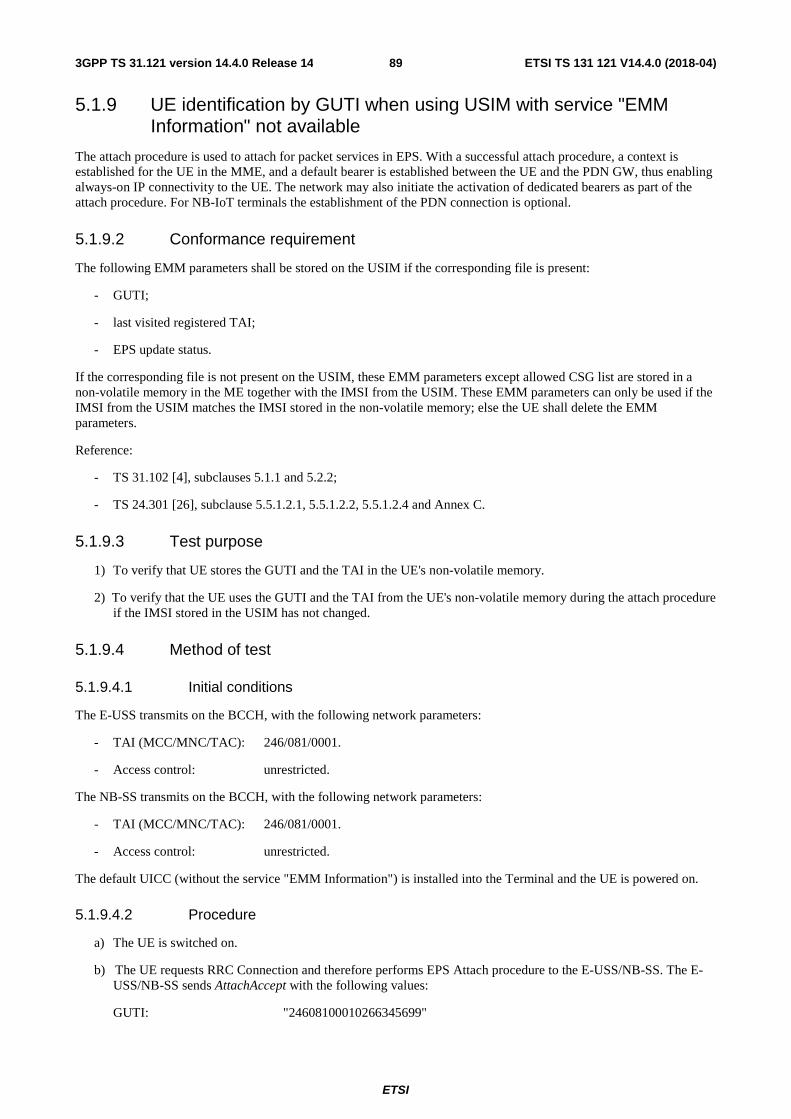
ETSI
ETSI TS 131 121 V14.4.0 (2018-04)893GPP TS 31.121 version 14.4.0 Release 14
5.1.9 UE identification by GUTI when using USIM with service "EMM Information" not available
The attach procedure is used to attach for packet services in EPS. With a successful attach procedure, a context is established for the UE in the MME, and a default bearer is established between the UE and the PDN GW, thus enabling always-on IP connectivity to the UE. The network may also initiate the activation of dedicated bearers as part of the attach procedure. For NB-IoT terminals the establishment of the PDN connection is optional.
5.1.9.2 Conformance requirement
The following EMM parameters shall be stored on the USIM if the corresponding file is present:
- GUTI;
- last visited registered TAI;
- EPS update status.
If the corresponding file is not present on the USIM, these EMM parameters except allowed CSG list are stored in a non-volatile memory in the ME together with the IMSI from the USIM. These EMM parameters can only be used if the IMSI from the USIM matches the IMSI stored in the non-volatile memory; else the UE shall delete the EMM parameters.
Reference:
- TS 31.102 [4], subclauses 5.1.1 and 5.2.2;
- TS 24.301 [26], subclause 5.5.1.2.1, 5.5.1.2.2, 5.5.1.2.4 and Annex C.
5.1.9.3 Test purpose
1) To verify that UE stores the GUTI and the TAI in the UE's non-volatile memory.
2) To verify that the UE uses the GUTI and the TAI from the UE's non-volatile memory during the attach procedure if the IMSI stored in the USIM has not changed.
5.1.9.4 Method of test
5.1.9.4.1 Initial conditions
The E-USS transmits on the BCCH, with the following network parameters:
- TAI (MCC/MNC/TAC): 246/081/0001.
- Access control: unrestricted.
The NB-SS transmits on the BCCH, with the following network parameters:
- TAI (MCC/MNC/TAC): 246/081/0001.
- Access control: unrestricted.
The default UICC (without the service "EMM Information") is installed into the Terminal and the UE is powered on.
5.1.9.4.2 Procedure
a) The UE is switched on.
b) The UE requests RRC Connection and therefore performs EPS Attach procedure to the E-USS/NB-SS. The E-USS/NB-SS sends AttachAccept with the following values:
GUTI: "24608100010266345699"

ETSI
ETSI TS 131 121 V14.4.0 (2018-04)903GPP TS 31.121 version 14.4.0 Release 14
TAI (MCC/MNC/TAC): 246/081/0001
c) The UE send AttachComplete.
d) The E-USS/NB-SS requests the release of the RRC Connection.
e) The UE is switched off.
f) The default UICC remains in use.
g) The Terminal is switched on.
h) The UE requests RRC Connection and therefore performs EPS Attach procedure to the E-USS/NB-SS.
5.1.9.5 Acceptance criteria
1) After step a) the UE shall read EFUST.
2) During step h) the UE shall include the GUTI "24608100010266345699" and the TAI 246/081/0001 in the AttachRequest message.
5.1.10 UE identification by GUTI when using USIM with service "EMM Information" available
5.1.10.1 Definition and applicability
The attach procedure is used to attach for packet services in EPS. With a successful attach procedure, a context is established for the UE in the MME, and a default bearer is established between the UE and the PDN GW, thus enabling always-on IP connectivity to the UE. The network may also initiate the activation of dedicated bearers as part of the attach procedure. For NB-IoT terminals the establishment of the PDN connection is optional.
5.1.10.2 Conformance requirement
The following EMM parameters shall be stored on the USIM if the corresponding file is present:
- GUTI;
- last visited registered TAI;
- EPS update status.
The presence and format of corresponding files on the USIM is specified in 3GPP TS 31.102 [4].
Reference:
- TS 31.102 [4], subclauses 5.1.1 and 5.2.2;
- TS 24.301 [26], subclause 5.5.1.2.1, 5.5.1.2.2, 5.5.1.2.4 and Annex C.

ETSI
ETSI TS 131 121 V14.4.0 (2018-04)913GPP TS 31.121 version 14.4.0 Release 14
5.1.10.3 Test purpose
1) To verify that UE includes the GUTI and TAI stored in EFEPSLOCI in the AttachRequest message.
2) To verify that the EMM parameters GUTI, Last Registered TAI sent in the AttachAccept message and the related EPS Update Status are correctly stored on the USIM if the corresponding file is present.
5.1.10.4 Method of test
5.1.10.4.1 Initial conditions
The E-USS transmits on the BCCH, with the following network parameters:
- TAI (MCC/MNC/TAC): 246/081/0002.
- Access control: unrestricted.
The NB-SS transmits on the BCCH, with the following network parameters:
- TAI (MCC/MNC/TAC): 246/081/0002.
- Access control: unrestricted.
The default E-UTRAN UICC is is used with the following exceptions:
EFEPSNSC (EPS NAS Security Context)
Logically: Key Set Identifier KSIASME: '01' ASME Key (KSIASME) : 32 byte key, any value Uplink NAS count: 00 Downlink NAS count: 01 Identifiers of selected NAS 01
integrity and encryption algorithm
Coding: B1 B2 B3 B4 B5 B6 B7 B8 … B39 Hex A0 34 80 01 01 81 20 xx … xx Coding: B40 B41 B42 B43 B44 B45 B46 B47 B48 B49 Hex 82 04 00 00 00 00 83 04 00 00 Coding: B50 B51 B52 B53 B54 Hex 00 01 84 01 01
5.1.10.4.2 Procedure
a) The UE is switched on.
b) The UE requests RRC Connection and therefore performs EPS Attach procedure to the E-USS/NB-SS. The E-USS/NB-SS sends AttachAccept with the following values:
GUTI: "24608100010266436587"
TAI (MCC/MNC/TAC): 246/081/0002
c) The UE send AttachComplete.
d) The E-USS/NB-SS requests the release of the RRC Connection.
5.1.10.5 Acceptance criteria
1) After step a) the UE shall read EFUST and EFEPSLOCI.
2) During step b) the UE shall include the GUTI and the Last visited registered TAI contained in EFEPSLOCI when sending the AttachRequest message.
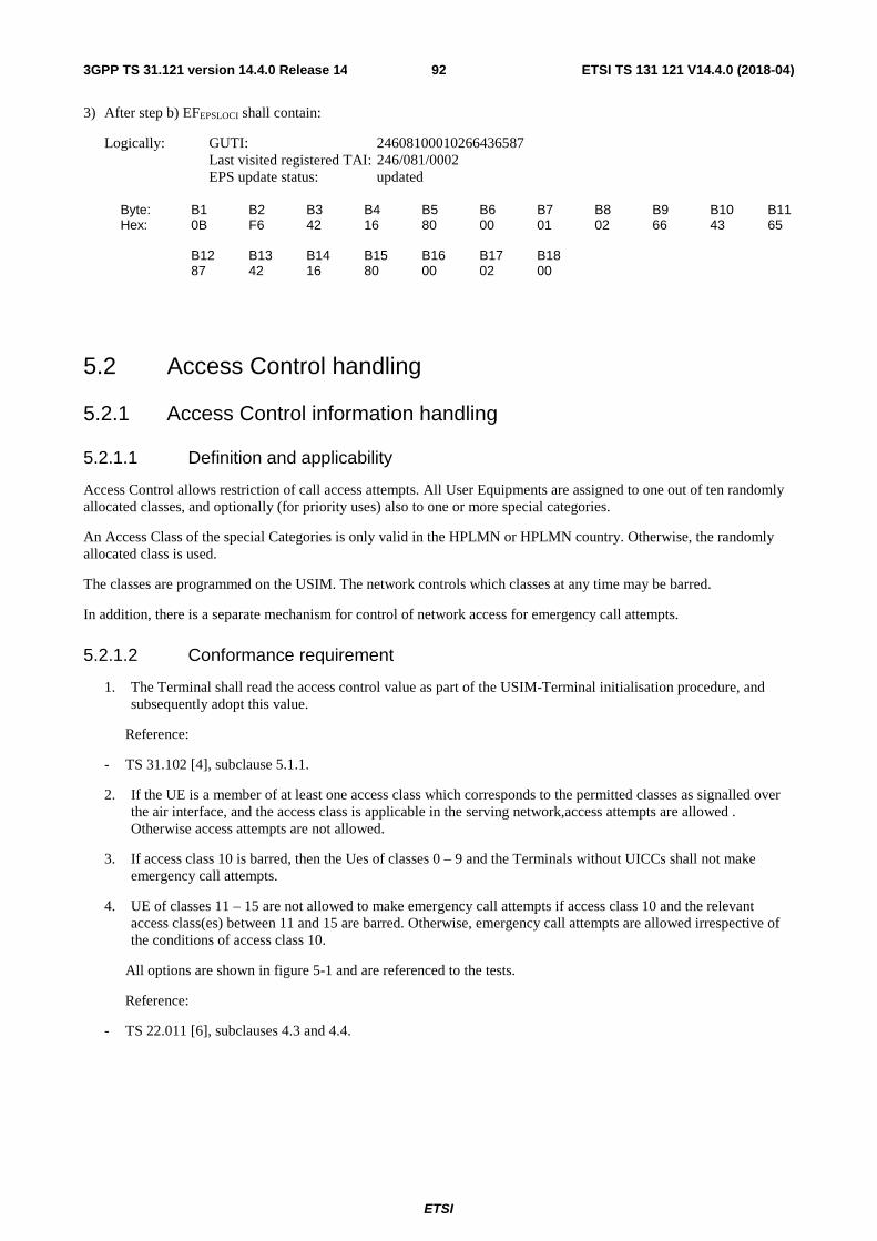
ETSI
ETSI TS 131 121 V14.4.0 (2018-04)923GPP TS 31.121 version 14.4.0 Release 14
3) After step b) EFEPSLOCI shall contain:
Logically: GUTI: 24608100010266436587 Last visited registered TAI: 246/081/0002 EPS update status: updated
Byte: B1 B2 B3 B4 B5 B6 B7 B8 B9 B10 B11 Hex: 0B F6 42 16 80 00 01 02 66 43 65 B12 B13 B14 B15 B16 B17 B18 87 42 16 80 00 02 00
5.2 Access Control handling
5.2.1 Access Control information handling
5.2.1.1 Definition and applicability
Access Control allows restriction of call access attempts. All User Equipments are assigned to one out of ten randomly allocated classes, and optionally (for priority uses) also to one or more special categories.
An Access Class of the special Categories is only valid in the HPLMN or HPLMN country. Otherwise, the randomly allocated class is used.
The classes are programmed on the USIM. The network controls which classes at any time may be barred.
In addition, there is a separate mechanism for control of network access for emergency call attempts.
5.2.1.2 Conformance requirement
1. The Terminal shall read the access control value as part of the USIM-Terminal initialisation procedure, and subsequently adopt this value.
Reference:
- TS 31.102 [4], subclause 5.1.1.
2. If the UE is a member of at least one access class which corresponds to the permitted classes as signalled over the air interface, and the access class is applicable in the serving network,access attempts are allowed . Otherwise access attempts are not allowed.
3. If access class 10 is barred, then the Ues of classes 0 – 9 and the Terminals without UICCs shall not make emergency call attempts.
4. UE of classes 11 – 15 are not allowed to make emergency call attempts if access class 10 and the relevant access class(es) between 11 and 15 are barred. Otherwise, emergency call attempts are allowed irrespective of the conditions of access class 10.
All options are shown in figure 5-1 and are referenced to the tests.
Reference:
- TS 22.011 [6], subclauses 4.3 and 4.4.

ETSI
ETSI TS 131 121 V14.4.0 (2018-04)933GPP TS 31.121 version 14.4.0 Release 14
5.2.1.3 Test purpose
1) To verify that the Terminal reads the access control value as part of the USIM-Terminal initialisation procedure, and subsequently adopts this value.
2) To verify that the UE controls its network access in accordance with its access control class and the conditions imposed by the serving network.
The tests verify Terminal performance for the following:
Tests (a) and (b) No UICC in Terminal.
Tests I to (e) UE with access class 0 to 9.
Test (f) UE with access class 11 and 15 not in HPLMN, and UE with access class 12,13 and 14 not in HPLMN country.
Test (g) and (h) UE with access class 11 and 15 in HPLMN, and UE with access class 12,13 and 14 in HPLMN country.
Each of the above are tested against all relevant combinations of access control and emergency call bits signalled by the network, as shown in table 5-1.
5.2.1.4 Method of test
5.2.1.4.1 Initial conditions
The USS (in case of a Terminal accessing UTRAN)/ SS (in case of a GERAN Terminal) transmits on the BCCH, with the following network parameters:
- Attach/detach: disabled.
- LAI (MCC/MNC/LAC): MCC, MNC: see table 5-1, LAC="0001".
- Access control: see table 5-1.
- RACH: see table 5-1.
The default UICC is installed in the Terminal containing IMSI and access control values as given in table 5-1 and the UE is powered on.
NOTE: Depending on the initial value of the EFLOCI, the UE may perform a location update. This shall be accepted by the USS/SS.
5.2.1.4.2 Coding details
USIM IMSI EFIMSI: Data Field "6F 07"
Logically: IMSI: "2460813579"
Coding: B1 B2 B3 B4 B5 B6 B7 B8 B9 Hex 06 21 64 80 31 75 F9 FF FF
Logically: IMSI: "24608135x9"
Coding: B1 B2 B3 B4 B5 B6 B7 B8 B9 Hex 06 21 64 80 31 x5 F9 FF FF
Access Control class EFACC: Data field "6F 78"
Reference:
7) See TS 31.102 [4].

ETSI
ETSI TS 131 121 V14.4.0 (2018-04)943GPP TS 31.121 version 14.4.0 Release 14
NETWORK (USS in case of a Terminal accessing UTRAN)
Access Class Barred List in SIB 3 should be set as table 5.1a:
Reference
7) TS 25.331 clause 10.3.2.1
NOTE: The first instance of the parameter corresponds to Access Class 0, the second to Access Class 1 and so on up to Access Class 15.
NETWORK (SS in case of a Terminal accessing GERAN)
RACH: As defined in TS 44.018 subclause 10.5.2.29.
NOTE: TS 44.018 also apply for the Radio Resource management for UMTS (see TS 24.008, subclause 10.5.2).
Octet 1 0111 1000 Octet 2 0000 1000 Octet 3 } Octet 4 } as table 5-1b
5.2.1.4.3 Procedure
a) Using the MMI or EMMI a normal call set-up is attempted.
b) Using the MMI or EMMI an emergency call set-up is attempted.
c) The test is repeated for each set of values in table 5-1.
5.2.1.5 Acceptance criteria
After steps a) and b) the UE shall access the network, or shall make no access attempt, in accordance with table 5-1.
NOTE 1: For conformance testing, to limit testing, in tesI(c), (d) and (e) it is only necessary that one of the access classes is tested. This access class may be chosen randomly.
NOTE 2: In tables 5-1a and 5-1b the following notation is used to describe the Access Class Barred IE: "0" = not barred, "1" =barred.
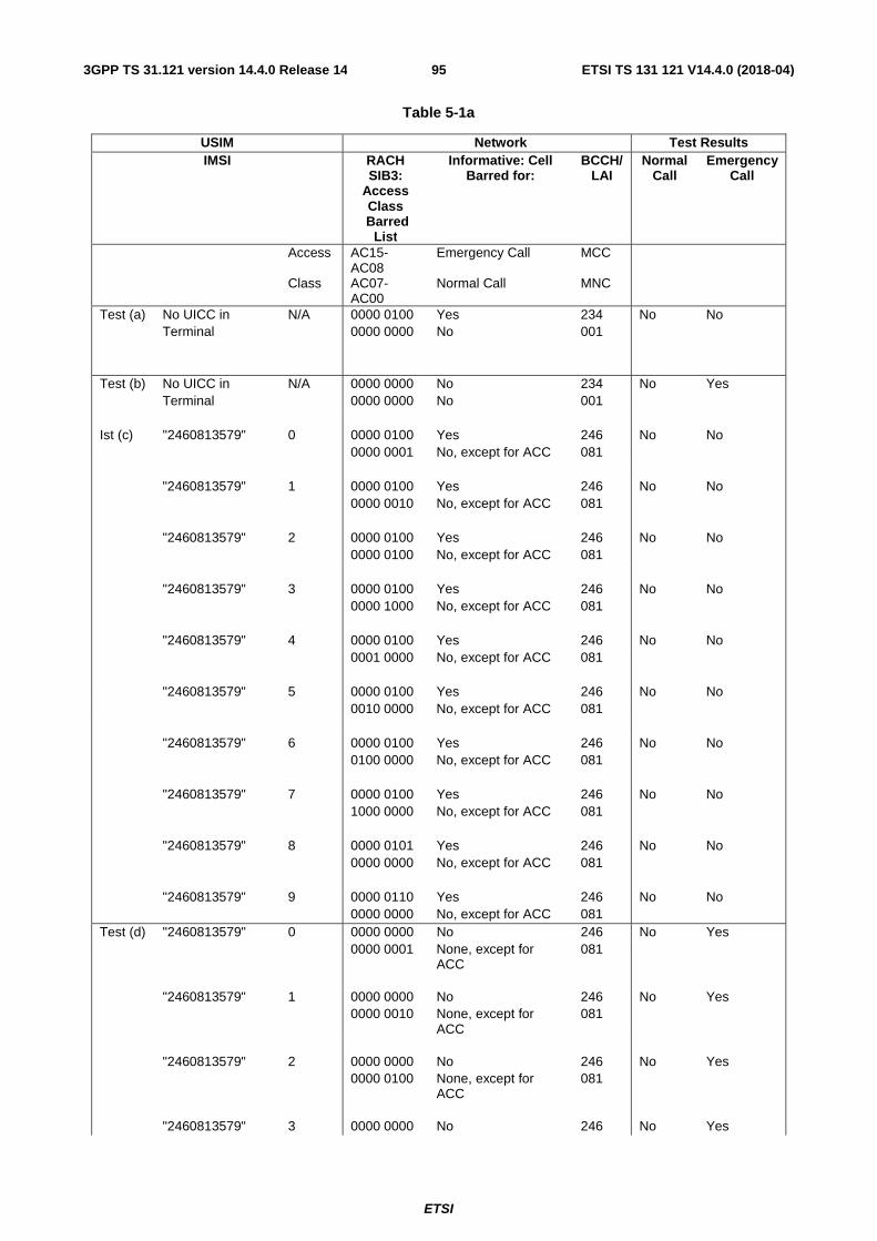
ETSI
ETSI TS 131 121 V14.4.0 (2018-04)953GPP TS 31.121 version 14.4.0 Release 14
Table 5-1a
USIM Network Test Results IMSI RACH
SIB3: Access Class
Barred List
Informative: Cell Barred for:
BCCH/LAI
Normal Call
Emergency Call
Access AC15-AC08
Emergency Call MCC
Class AC07-AC00
Normal Call MNC
Test (a) No UICC in N/A 0000 0100 Yes 234 No No Terminal 0000 0000 No 001 Test (b) No UICC in N/A 0000 0000 No 234 No Yes Terminal 0000 0000 No 001 Ist (c) "2460813579" 0 0000 0100 Yes 246 No No 0000 0001 No, except for ACC 081 "2460813579" 1 0000 0100 Yes 246 No No 0000 0010 No, except for ACC 081 "2460813579" 2 0000 0100 Yes 246 No No 0000 0100 No, except for ACC 081 "2460813579" 3 0000 0100 Yes 246 No No 0000 1000 No, except for ACC 081 "2460813579" 4 0000 0100 Yes 246 No No 0001 0000 No, except for ACC 081 "2460813579" 5 0000 0100 Yes 246 No No 0010 0000 No, except for ACC 081 "2460813579" 6 0000 0100 Yes 246 No No 0100 0000 No, except for ACC 081 "2460813579" 7 0000 0100 Yes 246 No No 1000 0000 No, except for ACC 081 "2460813579" 8 0000 0101 Yes 246 No No 0000 0000 No, except for ACC 081 "2460813579" 9 0000 0110 Yes 246 No No 0000 0000 No, except for ACC 081 Test (d) "2460813579" 0 0000 0000 No 246 No Yes 0000 0001 None, except for
ACC 081
"2460813579" 1 0000 0000 No 246 No Yes 0000 0010 None, except for
ACC 081
"2460813579" 2 0000 0000 No 246 No Yes 0000 0100 None, except for
ACC 081
"2460813579" 3 0000 0000 No 246 No Yes

ETSI
ETSI TS 131 121 V14.4.0 (2018-04)963GPP TS 31.121 version 14.4.0 Release 14
0000 1000 None, except for ACC
081
"2460813579" 4 0000 0000 No 246 No Yes 0001 0000 None, except for
ACC 081
"2460813579" 5 0000 0000 No 246 No Yes 0010 0000 None, except for
ACC 081
"2460813579" 6 0000 0000 No 246 No Yes 0100 0000 None, except for
ACC 081
"2460813579" 7 0000 0000 No 246 No Yes 1000 0000 None, except for
ACC 081
"2460813579" 8 0000 0001 No 246 No Yes 0000 0000 None, except for
ACC 081
"2460813579" 9 0000 0010 No 246 No Yes 0000 0000 None, except for
ACC 081

ETSI
ETSI TS 131 121 V14.4.0 (2018-04)973GPP TS 31.121 version 14.4.0 Release 14
Test (e) "2460813579" 0 1111 1011 No 246 Yes Yes 1111 1110 All, except ACC on
USIM 081
"2460813579" 1 1111 1011 No 246 Yes Yes 1111 1101 All, except ACC on
USIM 081
"2460813579" 2 1111 1011 No 246 Yes Yes 1111 1011 All, except ACC on
USIM 081
"2460813579" 3 1111 1011 No 246 Yes Yes 1111 0111 All, except ACC on
USIM 081
"2460813579" 4 1111 1011 No 246 Yes Yes 1110 1111 All, except ACC on
USIM 081
"2460813579" 5 1111 1011 No 246 Yes Yes 1101 1111 All, except ACC on
USIM 081
"2460813579" 6 1111 1011 No 246 Yes Yes 1011 1111 All, except ACC on
USIM 081
"2406813579" 7 1111 1011 No 246 Yes Yes 0111 1111 All, except ACC on
USIM 081
"2460813579" 8 1111 1010 No 246 Yes Yes 1111 1111 All, except ACC on
USIM 081
"2460813579" 9 1111 1001 No 246 Yes Yes 1111 1111 All, except ACC on
USIM 081
Test (f) "24608135x9" 11 & x 0000 0111 Yes 246 No No 1111 1111 All, except ACC
greater than 11 082
" 11 & x 0000 0011 No 246 No Yes 1111 1111 All, except ACC
greater than 11 082
" 11 & x 0000 0000 No 246 Yes Yes 0000 0000 None 082 "24608135x9" 12 & x 0000 0111 Yes 244 No No 1111 1111 All, except ACC
greater than 11 001
" 12 & x 0000 0011 No 244 No Yes 1111 1111 All, except ACC
greater than 11 001
" 12 & x 0000 0000 No 244 Yes Yes 0000 0000 None 001 "24608135x9" 13 & x 0000 0111 Yes 244 No No 1111 1111 All, except ACC
greater than 11 001
" 13 & x 0000 0011 No 244 No Yes

ETSI
ETSI TS 131 121 V14.4.0 (2018-04)983GPP TS 31.121 version 14.4.0 Release 14
1111 1111 All, except ACC greater than 11
001
" 13 & x 0000 0000 No 244 Yes Yes 0000 0000 None 001 "24608135x9" 14 & x 0000 0111 Yes 244 No No 1111 1111 All, except ACC
greater than 11 001
" 14 & x 0000 0011 No 244 No Yes 1111 1111 All, except ACC
greater than 11 001
" 14 & x 0000 0000 No 244 Yes Yes 0000 0000 None 001 "24608135x9" 15 & x 0000 0111 Yes 246 No No 1111 1111 All, except ACC
greater than 11 082
" 15 & x 0000 0011 No 246 No Yes 1111 1111 All, except ACC
greater than 11 082
" 15 & x 0000 0000 No 246 Yes Yes Set "x" to an
arbitrary value in the range 0 to 9
0000 0000 None 082
Test (g) "2460813579" 11 & x 0000 1111 Yes 246 No No 1111 1111 All normal ACC and
ACC on USIM 081
" 11 & x 0000 1011 No 246 No Yes 1111 1111 All normal ACC and
ACC on USIM 081
"2460813579" 12 & x 0001 0111 Yes 246 No No 1111 1111 All normal ACC and
ACC on USIM 082
" 12 & x 0001 0011 No 246 No Yes 1111 1111 All normal ACC and
ACC on USIM 082
"2460813579" 13 & x 0010 0111 Yes 246 No No 1111 1111 All normal ACC and
ACC on USIM 082
" 13 & x 0010 0011 No 246 No Yes 1111 1111 All normal ACC and
ACC on USIM 082
"2460813579" 14 & x 0100 0111 Yes 246 No No 1111 1111 All normal ACC and
ACC on USIM 082
" 14 & x 0100 0011 No 246 No Yes 1111 1111 All normal ACC and
ACC on USIM 082
"2460813579" 15 & x 1000 0111 Yes 246 No No 1111 1111 All normal ACC and
ACC on USIM 081

ETSI
ETSI TS 131 121 V14.4.0 (2018-04)993GPP TS 31.121 version 14.4.0 Release 14
" 15 & x 1000 0011 No 246 No Yes Set "x" to an
arbitrary value in the range 0 to 9
1111 1111 All normal ACC and ACC on USIM
081
Test (h) "2460813579" 11 & x 1111 0011 No 246 Yes Yes 1111 1111 All, except "special"
ACC on USIM 081
" 11 & x 1111 0111 Yes 246 Yes Yes 1111 1111 All, except "special"
ACC on USIM 081
"2460813579" 12 & x 1110 1011 No 246 Yes Yes 1111 1111 All, except "special"
ACC on USIM 082
" 12 & x 1110 1111 Yes 246 Yes Yes 1111 1111 All, except "special"
ACC on USIM 082
"2460813579" 13 & x 1101 1011 No 246 Yes Yes 1111 1111 All, except "special"
ACC on USIM 082
" 13 & x 1101 1111 Yes 246 Yes Yes 1111 1111 All, except "special"
ACC on USIM 082
"2460813579" 14 & x 1011 1011 No 246 Yes Yes 1111 1111 All, except "special"
ACC on USIM 082
" 14 & x 1011 1111 Yes 246 Yes Yes 1111 1111 All, except "special"
ACC on USIM 082
"2460813579" 15 & x 0111 1011 No 246 Yes Yes 1111 1111 All, except "special"
ACC on USIM 081
" 15 & x 0111 1111 Yes 246 Yes Yes Set "x" to an
arbitrary value in the range 0 to 9
1111 1111 All, except "special" ACC on USIM
081

ETSI
ETSI TS 131 121 V14.4.0 (2018-04)1003GPP TS 31.121 version 14.4.0 Release 14
Table 5-1b
USIM Network Test Results IMSI RACH Informative: Cell
Barred for: BCCH/
LAI Normal
Call Emergency
Call Access Octet 3 Emergency Call MCC Class Octet 4 Normal Call MNC Test (a) No UICC in N/A 0000 0100 Yes 234 No No Terminal 0000 0000 No 001 Test (b) No UICC in N/A 0000 0000 No 234 No Yes Terminal 0000 0000 No 001 Test (c) "2460813579" 0 0000 0100 Yes 246 No No 0000 0001 No, except for ACC 081 "2460813579" 1 0000 0100 Yes 246 No No 0000 0010 No, except for ACC 081 "2460813579" 2 0000 0100 Yes 246 No No 0000 0100 No, except for ACC 081 "2460813579" 3 0000 0100 Yes 246 No No 0000 1000 No, except for ACC 081 "2460813579" 4 0000 0100 Yes 246 No No 0001 0000 No, except for ACC 081 "2460813579" 5 0000 0100 Yes 246 No No 0010 0000 No, except for ACC 081 "2460813579" 6 0000 0100 Yes 246 No No 0100 0000 No, except for ACC 081 "2460813579" 7 0000 0100 Yes 246 No No 1000 0000 No, except for ACC 081 "2460813579" 8 0000 0101 Yes 246 No No 0000 0000 No, except for ACC 081 "2460813579" 9 0000 0110 Yes 246 No No 0000 0000 No, except for ACC 081 Test (d) "2460813579" 0 0000 0000 No 246 No Yes 0000 0001 None, except for ACC 081 "2460813579" 1 0000 0000 No 246 No Yes 0000 0010 None, except for ACC 081 "2460813579" 2 0000 0000 No 246 No Yes 0000 0100 None, except for ACC 081 "2460813579" 3 0000 0000 No 246 No Yes 0000 1000 None, except for ACC 081 "2460813579" 4 0000 0000 No 246 No Yes 0001 0000 None, except for ACC 081 "2460813579" 5 0000 0000 No 246 No Yes 0010 0000 None, except for ACC 081

ETSI
ETSI TS 131 121 V14.4.0 (2018-04)1013GPP TS 31.121 version 14.4.0 Release 14
"2460813579" 6 0000 0000 No 246 No Yes 0100 0000 None, except for ACC 081 "2460813579" 7 0000 0000 No 246 No Yes 1000 0000 None, except for ACC 081 "2460813579" 8 0000 0001 No 246 No Yes 0000 0000 None, except for ACC 081 "2460813579" 9 0000 0010 No 246 No Yes 0000 0000 None, except for ACC 081

ETSI
ETSI TS 131 121 V14.4.0 (2018-04)1023GPP TS 31.121 version 14.4.0 Release 14
Test (e) "2460813579" 0 1111 1011 No 246 Yes Yes 1111 1110 All, except ACC on
USIM 081
"2460813579" 1 1111 1011 No 246 Yes Yes 1111 1101 All, except ACC on
USIM 081
"2460813579" 2 1111 1011 No 246 Yes Yes 1111 1011 All, except ACC on
USIM 081
"2460813579" 3 1111 1011 No 246 Yes Yes 1111 0111 All, except ACC on
USIM 081
"2460813579" 4 1111 1011 No 246 Yes Yes 1110 1111 All, except ACC on
USIM 081
"2460813579" 5 1111 1011 No 246 Yes Yes 1101 1111 All, except ACC on
USIM 081
"2460813579" 6 1111 1011 No 246 Yes Yes 1011 1111 All, except ACC on
USIM 081
"2406813579" 7 1111 1011 No 246 Yes Yes 0111 1111 All, except ACC on
USIM 081
"2460813579" 8 1111 1010 No 246 Yes Yes 1111 1111 All, except ACC on
USIM 081
"2460813579" 9 1111 1001 No 246 Yes Yes 1111 1111 All, except ACC on
USIM 081
Test (f) "24608135x9" 11 & x 0000 0111 Yes 246 No No 1111 1111 All, except ACC
greater than 11 082
" 11 & x 0000 0011 No 246 No Yes 1111 1111 All, except ACC
greater than 11 082
" 11 & x 0000 0000 No 246 Yes Yes 0000 0000 None 082 "24608135x9" 12 & x 0000 0111 Yes 244 No No 1111 1111 All, except ACC
greater than 11 001
" 12 & x 0000 0011 No 244 No Yes 1111 1111 All, except ACC
greater than 11 001
" 12 & x 0000 0000 No 244 Yes Yes 0000 0000 None 001 "24608135x9" 13 & x 0000 0111 Yes 244 No No 1111 1111 All, except ACC
greater than 11 001
" 13 & x 0000 0011 No 244 No Yes

ETSI
ETSI TS 131 121 V14.4.0 (2018-04)1033GPP TS 31.121 version 14.4.0 Release 14
1111 1111 All, except ACC greater than 11
001
" 13 & x 0000 0000 No 244 Yes Yes 0000 0000 None 001 "24608135x9" 14 & x 0000 0111 Yes 244 No No 1111 1111 All, except ACC
greater than 11 001
" 14 & x 0000 0011 No 244 No Yes 1111 1111 All, except ACC
greater than 11 001
" 14 & x 0000 0000 No 244 Yes Yes 0000 0000 None 001 "24608135x9" 15 & x 0000 0111 Yes 246 No No 1111 1111 All, except ACC
greater than 11 082
" 15 & x 0000 0011 No 246 No Yes 1111 1111 All, except ACC
greater than 11 082
" 15 & x 0000 0000 No 246 Yes Yes Set "x" to an
arbitrary value in the range 0 to 9
0000 0000 None 082
Test (g) "2460813579" 11 & x 0000 1111 Yes 246 No No 1111 1111 All normal ACC and
ACC on USIM 081
" 11 & x 0000 1011 No 246 No Yes 1111 1111 All normal ACC and
ACC on USIM 081
"2460813579" 12 & x 0001 0111 Yes 246 No No 1111 1111 All normal ACC and
ACC on USIM 082
" 12 & x 0001 0011 No 246 No Yes 1111 1111 All normal ACC and
ACC on USIM 082
"2460813579" 13 & x 0010 0111 Yes 246 No No 1111 1111 All normal ACC and
ACC on USIM 082
" 13 & x 0010 0011 No 246 No Yes 1111 1111 All normal ACC and
ACC on USIM 082
"2460813579" 14 & x 0100 0111 Yes 246 No No 1111 1111 All normal ACC and
ACC on USIM 082
" 14 & x 0100 0011 No 246 No Yes 1111 1111 All normal ACC and
ACC on USIM 082
"2460813579" 15 & x 1000 0111 Yes 246 No No 1111 1111 All normal ACC and
ACC on USIM 081

ETSI
ETSI TS 131 121 V14.4.0 (2018-04)1043GPP TS 31.121 version 14.4.0 Release 14
" 15 & x 1000 0011 No 246 No Yes Set "x" to an
arbitrary value in the range 0 to 9
1111 1111 All normal ACC and ACC on USIM
081
Test (h) "2460813579" 11 & x 1111 0011 No 246 Yes Yes 1111 1111 All, except "special"
ACC on USIM 081
" 11 & x 1111 0111 Yes 246 Yes Yes 1111 1111 All, except "special"
ACC on USIM 081
"2460813579" 12 & x 1110 1011 No 246 Yes Yes 1111 1111 All, except "special"
ACC on USIM 082
" 12 & x 1110 1111 Yes 246 Yes Yes 1111 1111 All, except "special"
ACC on USIM 082
"2460813579" 13 & x 1101 1011 No 246 Yes Yes 1111 1111 All, except "special"
ACC on USIM 082
" 13 & x 1101 1111 Yes 246 Yes Yes 1111 1111 All, except "special"
ACC on USIM 082
"2460813579" 14 & x 1011 1011 No 246 Yes Yes 1111 1111 All, except "special"
ACC on USIM 082
" 14 & x 1011 1111 Yes 246 Yes Yes 1111 1111 All, except "special"
ACC on USIM 082
"2460813579" 15 & x 0111 1011 No 246 Yes Yes 1111 1111 All, except "special"
ACC on USIM 081
" 15 & x 0111 1111 Yes 246 Yes Yes Set "x" to an
arbitrary value in the range 0 to 9
1111 1111 All, except "special" ACC on USIM
081

ETSI
ETSI TS 131 121 V14.4.0 (2018-04)1053GPP TS 31.121 version 14.4.0 Release 14
ECs only, Test (b) applies
No (note)
Yes
EC Bit
ACC Class in USIM
UICC present
Yes No
HPLMN
HPLMN Country
Access Bit
'1'
'0'
'1' '0'
Access Bit
'1' '0'
No (note)
Yes
Access Class 0 - 9
Access Class 11 & 15
Access Class 12, 13 & 14
No network Access, Test (a) applies
Test (f) applies
Test (f) applies
EC Bit
'1'
'0'
All Calls, Test (h) applies
All Calls, Test (h) applies
EC Bit
'1'
'0'
ECs only, Test (d) applies
No Calls, Test (c) applies
EC Bit
'1'
'0'
ECs only, Test (g) applies
No Calls, Test (g) applies
EC Bit
'1'
'0'
All Calls, Test (e) applies
Normal Calls allowed, ECs NOT allowed Abnormal Case, No Test
NOTE: UE adopts Access Class 0-9, based on IMSI, see TS 22.011 [6]. Access Class in USIM, See TS 31.102 [4], EF ACC, "6F 78". Ecs: Emergency Calls. EC Bit: In case of GERAN:
Bit 3 of Octet 3 of RACH Control Parameters, See TS 44.018 Section 10.5.2.29. In case of UTRAN Access Class 10 defined in TS 22.011 clause 4.4.
AC Bit: See Access Class Barred List defined in TS 25.331 clause 10.3.2.1. HPLMN: Country means that the MCC of the VPLMN is the same as the MCC of the HPLMN.
Figure 5-1: Access control information

ETSI
ETSI TS 131 121 V14.4.0 (2018-04)1063GPP TS 31.121 version 14.4.0 Release 14
5.2.2 Access Control information handling for E-UTRAN/EPC
5.2.2.1 Definition and applicability
Access Control allows restriction of EPS bearer context activation access attempts. All User Equipments are assigned to one out of ten randomly allocated classes, and optionally (for priority uses) also to one or more special categories.
An Access Class of the special categories is only valid in the HPLMN or HPLMN country. Otherwise, the randomly allocated class is used.
The classes are programmed on the USIM. The network controls which classes at any time may be barred.
Emergency call handling is FFS.
5.2.2.2 Conformance requirement
1. The Terminal shall read the access control value as part of the USIM-Terminal initialisation procedure, and subsequently adopt this value.
Reference:
- TS 31.102 [4], subclause 5.1.1.
2. If the UE is a member of at least one access class which corresponds to the permitted classes as signalled over the air interface, and the access class is applicable in the serving network,access attempts are allowed . Otherwise access attempts are not allowed.
All options are shown in figure 5-2 and are referenced to the tests.
Reference:
- TS 22.011 [6], subclauses 4.3 and 4.4,
- TS 24.301 [26], subclause 5.5.1.2.6,
5.2.2.3 Test purpose
1) To verify that the Terminal reads the access control value as part of the USIM-Terminal initialisation procedure, and subsequently adopts this value.
2) To verify that the UE controls its network access in accordance with its access control class and the conditions imposed by the serving network.
The tests verify Terminal performance for the following:
Tests (a) to (b) UE with access class 0 to 9.
Test (c) UE with access class 11 and 15 not in HPLMN, and UE with access class 12,13 and 14 not in HPLMN country.
Test (d) and (e) UE with access class 11 and 15 in HPLMN, and UE with access class 12,13 and 14 in HPLMN country.
Each of the above are tested against all relevant combinations of access control bits signalled by the network, as shown in table 5-2.
5.2.2.4 Method of test
5.2.2.4.1 Initial conditions
The E-USS transmits on the BCCH, with the following network parameters:
- TAI (MCC/MNC/TAC): MCC, MNC: see table 5-2, TAC="0001".

ETSI
ETSI TS 131 121 V14.4.0 (2018-04)1073GPP TS 31.121 version 14.4.0 Release 14
- Access control: see table 5-2.
The default UICC is installed in the Terminal containing IMSI and access control values as given in table 5-2 and the UE is powered on.
NOTE: Depending on the initial value of the EFEPSLOCI, the UE may perform a location update. This shall be accepted by the E-USS.
5.2.2.4.2 Coding details
EFIMSI: Data Field "6F 07"
Logically: IMSI: "2460813579"
Coding: B1 B2 B3 B4 B5 B6 B7 B8 B9 Hex 06 21 64 80 31 75 F9 FF FF
Logically: IMSI: "24608135x9"
Coding: B1 B2 B3 B4 B5 B6 B7 B8 B9 Hex 06 21 64 80 31 x5 F9 FF FF
Access Control class EFACC: Data field "6F 78"
Reference:
• See TS 31.102 [4].
NETWORK (E-USS)
ac-BarringInfo in SystemInformationBlockType2 should be set as in table 5-2:
Reference
• TS 36.331 clause 6.3.1
5.2.2.4.3 Procedure
a) The terminal is switched on and performs registration if access is allowed for signalling according to table 5-2.
b) Using the MMI or EMMI a normal EPS bearer context setup is attempted if required by the test.
c) The test is repeated for each set of values in table 5-2.
5.2.2.5 Acceptance criteria
After step a) the UE shall access the network, or shall make no access attempt, in accordance with table 5-2.
In case in tables 5-2 the cell is indicated as
barred = yes, in these sub-sequences, the UE shall not establish a connection
barred = no, the UE shall establish a connection.
NOTE 1: For conformance testing, to limit testing, in tests (a), (b) and (c) it is only necessary that one of the access classes is tested. This access class may be chosen randomly.

ETSI
ETSI TS 131 121 V14.4.0 (2018-04)1083GPP TS 31.121 version 14.4.0 Release 14
Table 5-2
USIM Network IMSI Access
class:
SIBType2:
ac-BarringInfo
Cell barred for ATTACH and Default EPS bearer
context activation:
MCC MNC for
BCCH/LAI
Cell barred for second (non-default) EPS
bearer context setup:
Test (a) "2460813579" 0 SIBType2_A01 246 Yes
No 081
"2460813579" 1 SIBType2_A01 246 Yes
No 081
"2460813579" 2 SIBType2_A01 246 Yes
No 081
"2460813579" 3 SIBType2_A01 246 Yes
No 081
"2460813579" 4 SIBType2_A01 246 Yes
No 081
"2460813579" 5 SIBType2_A01 246 Yes
No 081
"2460813579" 6 SIBType2_A01 246 Yes
No 081
"2460813579" 7 SIBType2_A01 246 Yes
No 081
"2460813579" 8 SIBType2_A01 246 Yes
No 081
"2460813579" 9 SIBType2_A01 246 Yes
No 081
Test (b) "2460813579" 0 SIBType2_B01 246 No
No 081
"2460813579" 1 SIBType2_B01 246 No
No 081
"2460813579" 2 SIBType2_B01 246 No
No 081
"2460813579" 3 SIBType2_B01 246 No
No 081
"2460813579" 4 SIBType2_B01 246 No
No 081
"2460813579" 5 SIBType2_B01 246 No
No 081
"2460813579" 6 SIBType2_B01 246 No
No 081
"2460813579" 7 SIBType2_B01 246 No
No 081

ETSI
ETSI TS 131 121 V14.4.0 (2018-04)1093GPP TS 31.121 version 14.4.0 Release 14
"2460813579" 8 SIBType2_B01 246 No
No 081
"2460813579" 9 SIBType2_B01 246 No
No 081

ETSI
ETSI TS 131 121 V14.4.0 (2018-04)1103GPP TS 31.121 version 14.4.0 Release 14
Test (c) "24608135x9" 11 & x SIBType2_A01 No 246 Yes
082
" 11 & x SIBType2_C11_01 No 246 Yes
082
" 11 & x SIBType2_C11_02 Yes 246 N/A
(no registration possible as initial condition)
082 "24608135x9" 12 & x SIBType2_A01 244 Yes
No 001
" 12 & x SIBType2_C12_01 No 244 Yes
001
" 12 & x SIBType2_C12_02 Yes 244 N/A
(no registration possible as initial condition)
001 "24608135x9" 13 & x SIBType2_A01 No 244 Yes
001
" 13 & x SIBType2_C13_01 No 244 Yes
001
" 13 & x SIBType2_C13_02 Yes 244 N/A
(no registration possible as initial condition)
001 "24608135x9" 14 & x SIBType2_A01 No 244 Yes
001
" 14 & x SIBType2_C14_01 No 244 Yes
001
" 14 & x SIBType2_C14_02 Yes 244 N/A
(no registration possible as initial condition)
001 "24608135x9" 15 & x SIBType2_A01 No 246 Yes
082
" 15 & x SIBType2_C15_01 No 246 Yes
082
" 15 & x SIBType2_C15_02 Yes 246 N/A
(no registration possible as initial condition)
Set "x" to an arbitrary value in the range 0 to 9
082
Test (d) "2460813579" 11 & x SIBType2_C11_01 No 246 Yes
081
" 11 & x SIBType2_C11_02 Yes 246 N/A
081

ETSI
ETSI TS 131 121 V14.4.0 (2018-04)1113GPP TS 31.121 version 14.4.0 Release 14
"2460813579" 12 & x SIBType2_C12_01 No 246 Yes
082
" 12 & x SIBType2_C12_02 Yes 246 N/A
082
"2460813579" 13 & x SIBType2_C13_01 No 246 Yes
082
" 13 & x SIBType2_C13_02 Yes 246 N/A
082
"2460813579" 14 & x SIBType2_C14_01 No 246 Yes
082
" 14 & x SIBType2_C14_02 Yes 246 N/A
082
"2460813579" 15 & x SIBType2_C15_01 No 246 Yes
081
" 15 & x SIBType2_C15_02 Yes 246 N/A Set "x" to an
arbitrary value in the range 0 to 9
081
Test (e) "2460813579" 11 & x SIBType2_C11_03 No 246 No
081
"2460813579" 12 & x SIBType2_C12_03 No 246 No
082
"2460813579" 13 & x SIBType2_C13_03 No 246 No
082
"2460813579" 14 & x SIBType2_C14_03 No 246 No
082
"2460813579" 15 & x SIBType2_C15_03 No 246 No Set "x" to an
arbitrary value in the range 0 to 9
081

ETSI
ETSI TS 131 121 V14.4.0 (2018-04)1123GPP TS 31.121 version 14.4.0 Release 14
Specific message contents for Table 5-2
SystemInformationBlockType2 configuration SIBType2_A01
Derivation Path: 36.508, Table 4.4.3.3-1 Information Element Value/remark Comment Condition
SystemInformationBlockType2 ::= SEQUENCE { ac-BarringInfo SEQUENCE { ac-BarringForEmergency FALSE ac-BarringForMO-Signalling Not present ac-BarringForMO-Data SEQUENCE { ac-BarringFactor p00 ac-BarringTime s512 ac-BarringForSpecialAC '00000'B } } }
SystemInformationBlockType2 configuration SIBType2_B01
Derivation Path: 36.508, Table 4.4.3.3-1 Information Element Value/remark Comment Condition
SystemInformationBlockType2 ::= SEQUENCE { ac-BarringInfo SEQUENCE { ac-BarringForEmergency FALSE ac-BarringForMO-Signalling Not present ac-BarringForMO-Data Not present } }
SystemInformationBlockType2 configuration SIBType2_C11_01
Derivation Path: 36.508, Table 4.4.3.3-1 Information Element Value/remark Comment Condition
SystemInformationBlockType2 ::= SEQUENCE { ac-BarringInfo SEQUENCE { ac-BarringForEmergency FALSE ac-BarringForMO-Signalling Not present ac-BarringForMO-Data SEQUENCE { ac-BarringFactor p00 ac-BarringTime s512 ac-BarringForSpecialAC '10000'B } } }
SystemInformationBlockType2 configuration SIBType2_C11_02
Derivation Path: 36.508, Table 4.4.3.3-1 Information Element Value/remark Comment Condition
SystemInformationBlockType2 ::= SEQUENCE { ac-BarringInfo SEQUENCE { ac-BarringForEmergency FALSE ac-BarringForMO-Signalling SEQUENCE { ac-BarringFactor p00 ac-BarringTime s512 ac-BarringForSpecialAC '10000'B } ac-BarringForMO-Data Not present } }

ETSI
ETSI TS 131 121 V14.4.0 (2018-04)1133GPP TS 31.121 version 14.4.0 Release 14
SystemInformationBlockType2 configuration SIBType2_C11_03
Derivation Path: 36.508, Table 4.4.3.3-1 Information Element Value/remark Comment Condition
SystemInformationBlockType2 ::= SEQUENCE { ac-BarringInfo SEQUENCE { ac-BarringForEmergency FALSE ac-BarringForMO-Signalling Not present ac-BarringForMO-Data SEQUENCE { ac-BarringFactor p00 ac-BarringTime s512 ac-BarringForSpecialAC '01111'B } } }
SystemInformationBlockType2 configuration SIBType2_C12_01
Derivation Path: 36.508, Table 4.4.3.3-1 Information Element Value/remark Comment Condition
SystemInformationBlockType2 ::= SEQUENCE { ac-BarringInfo SEQUENCE { ac-BarringForEmergency FALSE ac-BarringForMO-Signalling Not present ac-BarringForMO-Data SEQUENCE { ac-BarringFactor p00 ac-BarringTime s512 ac-BarringForSpecialAC '01000'B } } }

ETSI
ETSI TS 131 121 V14.4.0 (2018-04)1143GPP TS 31.121 version 14.4.0 Release 14
SystemInformationBlockType2 configuration SIBType2_C12_02
Derivation Path: 36.508, Table 4.4.3.3-1 Information Element Value/remark Comment Condition
SystemInformationBlockType2 ::= SEQUENCE { ac-BarringInfo SEQUENCE { ac-BarringForEmergency FALSE ac-BarringForMO-Signalling SEQUENCE { ac-BarringFactor p00 ac-BarringTime s512 ac-BarringForSpecialAC '01000'B } ac-BarringForMO-Data Not present } }
SystemInformationBlockType2 configuration SIBType2_C12_03
Derivation Path: 36.508, Table 4.4.3.3-1 Information Element Value/remark Comment Condition
SystemInformationBlockType2 ::= SEQUENCE { ac-BarringInfo SEQUENCE { ac-BarringForEmergency FALSE ac-BarringForMO-Signalling Not present ac-BarringForMO-Data SEQUENCE { ac-BarringFactor p00 ac-BarringTime s512 ac-BarringForSpecialAC '10111'B } } }
SystemInformationBlockType2 configuration SIBType2_C13_01
Derivation Path: 36.508, Table 4.4.3.3-1 Information Element Value/remark Comment Condition
SystemInformationBlockType2 ::= SEQUENCE { ac-BarringInfo SEQUENCE { ac-BarringForEmergency FALSE ac-BarringForMO-Signalling Not present ac-BarringForMO-Data SEQUENCE { ac-BarringFactor p00 ac-BarringTime s512 ac-BarringForSpecialAC '00100'B } } }

ETSI
ETSI TS 131 121 V14.4.0 (2018-04)1153GPP TS 31.121 version 14.4.0 Release 14
SystemInformationBlockType2 configuration SIBType2_C13_02
Derivation Path: 36.508, Table 4.4.3.3-1 Information Element Value/remark Comment Condition
SystemInformationBlockType2 ::= SEQUENCE { ac-BarringInfo SEQUENCE { ac-BarringForEmergency FALSE ac-BarringForMO-Signalling SEQUENCE { ac-BarringFactor p00 ac-BarringTime s512 ac-BarringForSpecialAC '00100'B } ac-BarringForMO-Data Not present } }
SystemInformationBlockType2 configuration SIBType2_C13_03
Derivation Path: 36.508, Table 4.4.3.3-1 Information Element Value/remark Comment Condition
SystemInformationBlockType2 ::= SEQUENCE { ac-BarringInfo SEQUENCE { ac-BarringForEmergency FALSE ac-BarringForMO-Signalling Not present ac-BarringForMO-Data SEQUENCE { ac-BarringFactor p00 ac-BarringTime s512 ac-BarringForSpecialAC '11011'B } } }
SystemInformationBlockType2 configuration SIBType2_C14_01
Derivation Path: 36.508, Table 4.4.3.3-1 Information Element Value/remark Comment Condition
SystemInformationBlockType2 ::= SEQUENCE { ac-BarringInfo SEQUENCE { ac-BarringForEmergency FALSE ac-BarringForMO-Signalling Not present ac-BarringForMO-Data SEQUENCE { ac-BarringFactor p00 ac-BarringTime s512 ac-BarringForSpecialAC '00010'B } } }

ETSI
ETSI TS 131 121 V14.4.0 (2018-04)1163GPP TS 31.121 version 14.4.0 Release 14
SystemInformationBlockType2 configuration SIBType2_C14_02
Derivation Path: 36.508, Table 4.4.3.3-1 Information Element Value/remark Comment Condition
SystemInformationBlockType2 ::= SEQUENCE { ac-BarringInfo SEQUENCE { ac-BarringForEmergency FALSE ac-BarringForMO-Signalling SEQUENCE { ac-BarringFactor p00 ac-BarringTime s512 ac-BarringForSpecialAC '00010'B } ac-BarringForMO-Data Not present } }
SystemInformationBlockType2 configuration SIBType2_C14_03
Derivation Path: 36.508, Table 4.4.3.3-1 Information Element Value/remark Comment Condition
SystemInformationBlockType2 ::= SEQUENCE { ac-BarringInfo SEQUENCE { ac-BarringForEmergency FALSE ac-BarringForMO-Signalling Not present ac-BarringForMO-Data SEQUENCE { ac-BarringFactor p00 ac-BarringTime s512 ac-BarringForSpecialAC '11101'B } } }
SystemInformationBlockType2 configuration SIBType2_C15_01
Derivation Path: 36.508, Table 4.4.3.3-1 Information Element Value/remark Comment Condition
SystemInformationBlockType2 ::= SEQUENCE { ac-BarringInfo SEQUENCE { ac-BarringForEmergency FALSE ac-BarringForMO-Signalling Not present ac-BarringForMO-Data SEQUENCE { ac-BarringFactor p00 ac-BarringTime s512 ac-BarringForSpecialAC '00001'B } } }
SystemInformationBlockType2 configuration SIBType2_C15_02
Derivation Path: 36.508, Table 4.4.3.3-1 Information Element Value/remark Comment Condition
SystemInformationBlockType2 ::= SEQUENCE { ac-BarringInfo SEQUENCE { ac-BarringForEmergency FALSE ac-BarringForMO-Signalling SEQUENCE { ac-BarringFactor p00 ac-BarringTime s512 ac-BarringForSpecialAC '00001'B } ac-BarringForMO-Data Not present } }

ETSI
ETSI TS 131 121 V14.4.0 (2018-04)1173GPP TS 31.121 version 14.4.0 Release 14
SystemInformationBlockType2 configuration SIBType2_C15_03
Derivation Path: 36.508, Table 4.4.3.3-1 Information Element Value/remark Comment Condition
SystemInformationBlockType2 ::= SEQUENCE { ac-BarringInfo SEQUENCE { ac-BarringForEmergency FALSE ac-BarringForMO-Signalling Not present ac-BarringForMO-Data SEQUENCE { ac-BarringFactor p00 ac-BarringTime s512 ac-BarringForSpecialAC '11110'B } } }
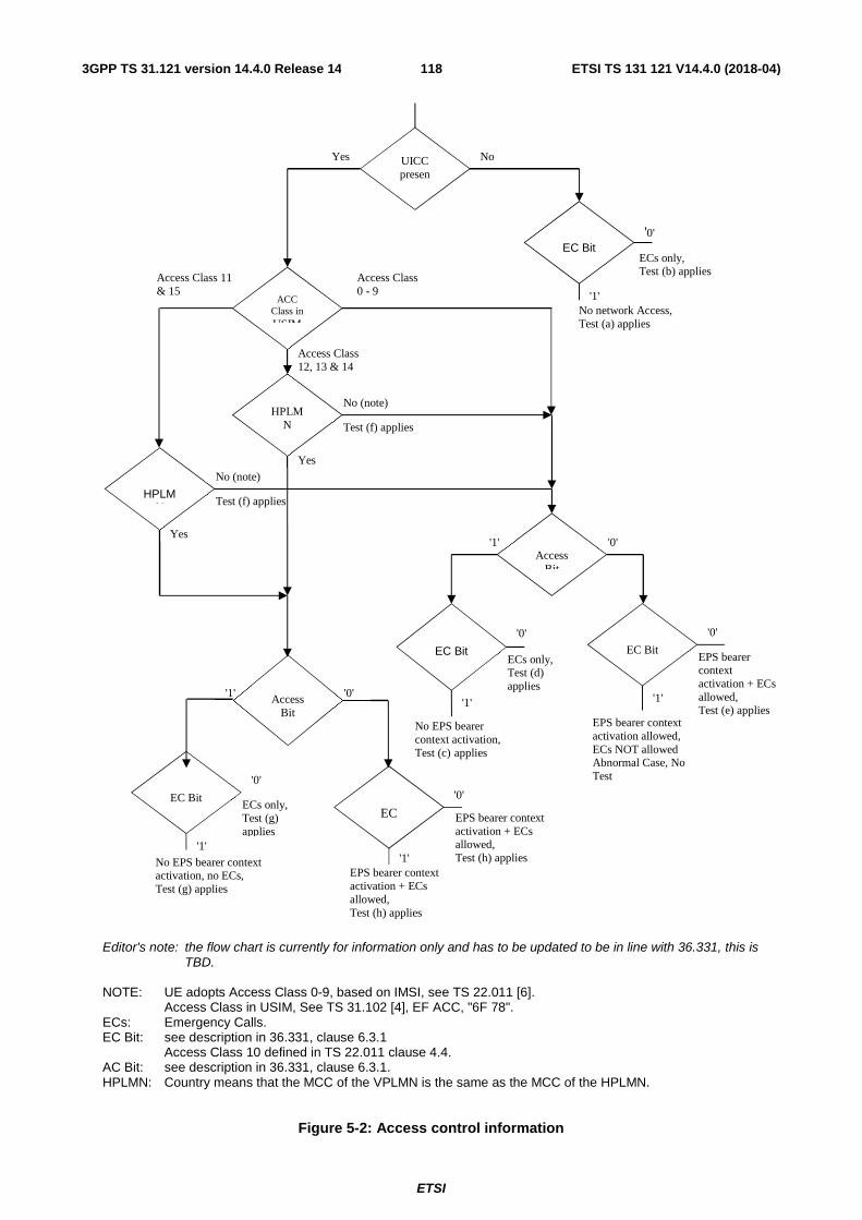
ETSI
ETSI TS 131 121 V14.4.0 (2018-04)1183GPP TS 31.121 version 14.4.0 Release 14
Editor's note: the flow chart is currently for information only and has to be updated to be in line with 36.331, this is
TBD. NOTE: UE adopts Access Class 0-9, based on IMSI, see TS 22.011 [6]. Access Class in USIM, See TS 31.102 [4], EF ACC, "6F 78". ECs: Emergency Calls. EC Bit: see description in 36.331, clause 6.3.1
Access Class 10 defined in TS 22.011 clause 4.4. AC Bit: see description in 36.331, clause 6.3.1. HPLMN: Country means that the MCC of the VPLMN is the same as the MCC of the HPLMN.
Figure 5-2: Access control information
ECs only, Test (b) applies
No (note)
EC Bit
ACC Class in USIM
UICC presen
t
Yes No
HPLMN
HPLMN
Access Bit
'1'
'0'
No (note)
Access Class 0 - 9
Access Class 11 & 15
Access Class 12, 13 & 14
No network Access, Test (a) applies
Test (f) applies
Test (f) applies
Access Bit
'1' '0'
EC Bit
'1'
'0'
ECs only, Test (d) applies
No EPS bearer context activation, Test (c) applies
EC Bit
'1'
'0'
EPS bearer context activation + ECs allowed, Test (e) applies
EPS bearer context activation allowed, ECs NOT allowed Abnormal Case, No Test
EC Bit
'1'
'0'
EPS bearer context activation + ECs allowed, Test (h) applies
EPS bearer context activation + ECs allowed, Test (h) applies
EC Bit
'1'
'0'
ECs only, Test (g) applies
No EPS bearer context activation, no ECs, Test (g) applies
Yes
'1' '0' Yes

ETSI
ETSI TS 131 121 V14.4.0 (2018-04)1193GPP TS 31.121 version 14.4.0 Release 14
5.2.3 Access Control information handling for NB-IoT
5.2.3.1 Definition and applicability
Access Control allows restriction on RRC connection establishment attempts. All User Equipments are assigned to one out of ten randomly allocated classes, and optionally (for priority uses) also to one or more special categories.
An Access Class of the special categories is only valid in the HPLMN or HPLMN country. Otherwise, the randomly allocated class is used.
The classes are programmed on the USIM. The network controls which classes at any time may be barred.
5.2.3.2 Conformance requirement
1. The Terminal shall read the access control value as part of the USIM-Terminal initialisation procedure, and subsequently adopt this value.
Reference:
- TS 31.102 [4], subclause 5.1.1.
2. If the UE is a member of at least one access class which corresponds to the permitted classes as signalled over the air interface, and the access class is applicable in the serving network,access attempts are allowed . Otherwise access attempts are not allowed.
Reference:
- TS 22.011 [6], subclauses 4.3 and 4.4,
- TS 24.301 [26], subclause 5.5.1.2.6,
5.2.3.3 Test purpose
1) To verify that the Terminal reads the access control value as part of the USIM-Terminal initialisation procedure, and subsequently adopts this value.
2) To verify that the UE controls its network access in accordance with its access control class and the conditions imposed by the serving network.
The tests verify Terminal performance for the following:
Tests (a) to (b) UE with access class 0 to 9.
Test (c) UE with access class 11 and 15 not in HPLMN, and UE with access class 12,13 and 14 not in HPLMN country.
Test (d) and (e) UE with access class 11 and 15 in HPLMN, and UE with access class 12,13 and 14 in HPLMN country.
Each of the above are tested against all relevant combinations of access control bits signalled by the network, as shown in table 5-3.
5.2.3.4 Method of test
5.2.3.4.1 Initial conditions
The NB-SS transmits on the BCCH, with the following network parameters:
- TAI (MCC/MNC/TAC): MCC, MNC: see table 5-3, TAC="0001".
- Access control: see table 5-3.

ETSI
ETSI TS 131 121 V14.4.0 (2018-04)1203GPP TS 31.121 version 14.4.0 Release 14
The default UICC is installed in the Terminal containing IMSI and access control values as given in table 5-3 and the UE is powered on.
NOTE: Depending on the initial value of the EFEPSLOCI, the UE may perform a location update. This shall be accepted by the NB-SS.
5.2.3.4.2 Coding details
EFIMSI: Data Field "6F 07"
Logically: IMSI: "2460813579"
Coding: B1 B2 B3 B4 B5 B6 B7 B8 B9 Hex 06 21 64 80 31 75 F9 FF FF
Logically: IMSI: "24608135x9"
Coding: B1 B2 B3 B4 B5 B6 B7 B8 B9 Hex 06 21 64 80 31 x5 F9 FF FF
Access Control class EFACC: Data field "6F 78"
Reference:
• See TS 31.102 [4].
NETWORK (NB-SS)
ab-Enabled included in MasterInformationBlock-NB is set to TRUE and in SystemInformationBlockType14-NB should be set as in table 5-3.
Reference
• TS 36.331 clause 6.7.3.1.
5.2.3.4.3 Procedure
a) The terminal is switched on and performs registration if access is allowed for signalling according to table 5-3.
b) The test is repeated for each set of values in table 5-3.
5.2.3.5 Acceptance criteria
After step a) the UE shall access the network, or shall make no access attempt, in accordance with table 5-3.
In case in tables 5-3 the cell is indicated as
barred = yes, in these sub-sequences, the UE shall not establish a connection
barred = no, the UE shall establish a connection.
NOTE 1: For conformance testing, to limit testing, in tests (a), (b) and (c) it is only necessary that one of the access classes is tested. This access class may be chosen randomly.

ETSI
ETSI TS 131 121 V14.4.0 (2018-04)1213GPP TS 31.121 version 14.4.0 Release 14
Table 5-3
USIM Network IMSI AC
SIBType14-NB:
ac-Param
Cell barred for RRC connection establishment /
resume :
MCC MNC for
BCCH/LAI
Test (a) "2460813579" 0 SIBType14-NB_A00 Yes 246 081 "2460813579" 1 SIBType14-NB_A01 Yes 246 081 "2460813579" 2 SIBType14-NB_A02 Yes 246 081 "2460813579" 3 SIBType14-NB_A03 Yes 246 081 "2460813579" 4 SIBType14-NB_A04 Yes 246 081
"2460813579" 5 SIBType14-NB_A05 Yes 246 081
"2460813579" 6 SIBType14-NB_A06 Yes 246 081 "2460813579" 7 SIBType14-NB_A07 Yes 246 081
"2460813579" 8 SIBType14-NB_A08 Yes 246 081
"2460813579" 9 SIBType14-NB_A09 Yes 246 081
Test (b) "2460813579" 0 SIBType14-NB_B01 No 246 081 "2460813579" 1 SIBType14-NB_B01 No 246 081 "2460813579" 2 SIBType14-NB_B01 No 246 081 "2460813579" 3 SIBType14-NB_B01 No 246 081 "2460813579" 4 SIBType14-NB_B01 No 246 081 "2460813579" 5 SIBType14-NB_B01 No 246 081
"2460813579" 6 SIBType14-NB_B01 No 246 081
"2460813579" 7 SIBType14-NB_B01 No 246 081
"2460813579" 8 SIBType14-NB_B01 No 246 081
"2460813579" 9 SIBType14-NB_B01 No 246 081

ETSI
ETSI TS 131 121 V14.4.0 (2018-04)1223GPP TS 31.121 version 14.4.0 Release 14
Test (c) "24608135x9" 11 & 2 SIBType14-NB_C11_01 Yes 246 082 " 11 & 2 SIBType14-NB_C11_02 Yes 246 082 "24608135x9" 12 & 5 SIBType14-NB_C12_01 Yes 244 001 " 12 & 5 SIBType14-NB_C12_02 Yes 244 001 "24608135x9" 13 & 4 SIBType14-NB_C13_01 Yes 244 001 " 13 & 4 SIBType14-NB_C13_02 Yes 244 001 "24608135x9" 14 & 9 SIBType14-NB_C14_01 Yes 244 001 " 14 & 9 SIBType14-NB_C14_02 Yes 244 001 "24608135x9" 15 & 0 SIBType14-NB_C15_01 Yes 246 082
" 15 & 0 SIBType14-NB_C15_02 Yes 246 082
Test (d) "2460813579" 11 & 2 SIBType14-NB_C11_01 Yes 246 081 "2460813579" 12 & 5 SIBType14-NB_C12_01 Yes 246 082 "2460813579" 13 & 4 SIBType14-NB_C13_01 Yes 246 082 "2460813579" 14 & 9 SIBType14-NB_C14_01 Yes 246 082 "2460813579" 15 & 0 SIBType14-NB_C15_01 Yes 246 081
Test (e) "2460813579" 11 & 2 SIBType14-NB_C11_03 No 246 081 "2460813579" 12 & 5 SIBType14-NB_C12_03 No 246 082 "2460813579" 13 & 4 SIBType14-NB_C13_03 No 246 082 "2460813579" 14 & 9 SIBType14-NB_C14_03 No 246 082 "2460813579" 15 & 0 SIBType14-NB_C15_03 No 246 081

ETSI
ETSI TS 131 121 V14.4.0 (2018-04)1233GPP TS 31.121 version 14.4.0 Release 14
Specific message contents for Table 5-3
SystemInformationBlockType14-NB configuration SIBType14-NB_A00
Derivation Path: 36.508 Table 8.1.4.3.3-5 Information Element Value/remark Comment Condition
SystemInformationBlockType14-NB-r13 ::= SEQUENCE {
ab-Param-r13 CHOICE { ab-Common-r13 SEQUENCE { ab-Category-r13 a ab-BarringBitmap-r13 ‘1000000000’B ab-BarringExceptionData-r13 Not present ab-BarringForSpecialAC-r13 ‘00000’B } } lateNonCriticalExtension Not present }
SystemInformationBlockType14-NB configuration SIBType14-NB_A01
Derivation Path: 36.508 Table 8.1.4.3.3-5 Information Element Value/remark Comment Condition
SystemInformationBlockType14-NB-r13 ::= SEQUENCE {
ab-Param-r13 CHOICE { ab-Common-r13 SEQUENCE { ab-Category-r13 a ab-BarringBitmap-r13 ‘0100000000’B ab-BarringExceptionData-r13 Not present ab-BarringForSpecialAC-r13 ‘00000’B } } lateNonCriticalExtension Not present }
SystemInformationBlockType14-NB configuration SIBType14-NB_A02
Derivation Path: 36.508 Table 8.1.4.3.3-5 Information Element Value/remark Comment Condition
SystemInformationBlockType14-NB-r13 ::= SEQUENCE {
ab-Param-r13 CHOICE { ab-Common-r13 SEQUENCE { ab-Category-r13 a ab-BarringBitmap-r13 ‘0010000000’B ab-BarringExceptionData-r13 Not present ab-BarringForSpecialAC-r13 ‘00000’B } } lateNonCriticalExtension Not present }

ETSI
ETSI TS 131 121 V14.4.0 (2018-04)1243GPP TS 31.121 version 14.4.0 Release 14
SystemInformationBlockType14-NB configuration SIBType14-NB_A03
Derivation Path: 36.508 Table 8.1.4.3.3-5 Information Element Value/remark Comment Condition
SystemInformationBlockType14-NB-r13 ::= SEQUENCE {
ab-Param-r13 CHOICE { ab-Common-r13 SEQUENCE { ab-Category-r13 a ab-BarringBitmap-r13 ‘0001000000’B ab-BarringExceptionData-r13 Not present ab-BarringForSpecialAC-r13 ‘00000’B } } lateNonCriticalExtension Not present }
SystemInformationBlockType14-NB configuration SIBType14-NB_A04
Derivation Path: 36.508 Table 8.1.4.3.3-5 Information Element Value/remark Comment Condition
SystemInformationBlockType14-NB-r13 ::= SEQUENCE {
ab-Param-r13 CHOICE { ab-Common-r13 SEQUENCE { ab-Category-r13 a ab-BarringBitmap-r13 ‘0000100000’B ab-BarringExceptionData-r13 Not present ab-BarringForSpecialAC-r13 ‘00000’B } } lateNonCriticalExtension Not present }
SystemInformationBlockType14-NB configuration SIBType14-NB_A05
Derivation Path: 36.508 Table 8.1.4.3.3-5 Information Element Value/remark Comment Condition
SystemInformationBlockType14-NB-r13 ::= SEQUENCE {
ab-Param-r13 CHOICE { ab-Common-r13 SEQUENCE { ab-Category-r13 a ab-BarringBitmap-r13 ‘0000010000’B ab-BarringExceptionData-r13 Not present ab-BarringForSpecialAC-r13 ‘00000’B } } lateNonCriticalExtension Not present }

ETSI
ETSI TS 131 121 V14.4.0 (2018-04)1253GPP TS 31.121 version 14.4.0 Release 14
SystemInformationBlockType14-NB configuration SIBType14-NB_A06
Derivation Path: 36.508 Table 8.1.4.3.3-5 Information Element Value/remark Comment Condition
SystemInformationBlockType14-NB-r13 ::= SEQUENCE {
ab-Param-r13 CHOICE { ab-Common-r13 SEQUENCE { ab-Category-r13 a ab-BarringBitmap-r13 ‘0000001000’B ab-BarringExceptionData-r13 Not present ab-BarringForSpecialAC-r13 ‘00000’B } } lateNonCriticalExtension Not present }
SystemInformationBlockType14-NB configuration SIBType14-NB_A07
Derivation Path: 36.508 Table 8.1.4.3.3-5 Information Element Value/remark Comment Condition
SystemInformationBlockType14-NB-r13 ::= SEQUENCE {
ab-Param-r13 CHOICE { ab-Common-r13 SEQUENCE { ab-Category-r13 a ab-BarringBitmap-r13 ‘0000000100’B ab-BarringExceptionData-r13 Not present ab-BarringForSpecialAC-r13 ‘00000’B } } lateNonCriticalExtension Not present }
SystemInformationBlockType14-NB configuration SIBType14-NB_A08
Derivation Path: 36.508 Table 8.1.4.3.3-5 Information Element Value/remark Comment Condition
SystemInformationBlockType14-NB-r13 ::= SEQUENCE {
ab-Param-r13 CHOICE { ab-Common-r13 SEQUENCE { ab-Category-r13 a ab-BarringBitmap-r13 ‘0000000010’B ab-BarringExceptionData-r13 Not present ab-BarringForSpecialAC-r13 ‘00000’B } } lateNonCriticalExtension Not present }

ETSI
ETSI TS 131 121 V14.4.0 (2018-04)1263GPP TS 31.121 version 14.4.0 Release 14
SystemInformationBlockType14-NB configuration SIBType14-NB_A09
Derivation Path: 36.508 Table 8.1.4.3.3-5 Information Element Value/remark Comment Condition
SystemInformationBlockType14-NB-r13 ::= SEQUENCE {
ab-Param-r13 CHOICE { ab-Common-r13 SEQUENCE { ab-Category-r13 a ab-BarringBitmap-r13 ‘0000000001’B ab-BarringExceptionData-r13 Not present ab-BarringForSpecialAC-r13 ‘00000’B } } lateNonCriticalExtension Not present }
SystemInformationBlockType14-NB configuration SIBType14-NB_B01
Derivation Path: 36.508 Table 8.1.4.3.3-5 Information Element Value/remark Comment Condition
SystemInformationBlockType14-NB-r13 ::= SEQUENCE {
ab-Param-r13 CHOICE { ab-Common-r13 SEQUENCE { ab-Category-r13 a ab-BarringBitmap-r13 ‘0000000000’B ab-BarringExceptionData-r13 Not present ab-BarringForSpecialAC-r13 ‘00000’B } } lateNonCriticalExtension Not present }
SystemInformationBlockType14-NB configuration SIBType14-NB_C11_01
Derivation Path: 36.508 Table 8.1.4.3.3-5 Information Element Value/remark Comment Condition
SystemInformationBlockType14-NB-r13 ::= SEQUENCE {
ab-Param-r13 CHOICE { ab-Common-r13 SEQUENCE { ab-Category-r13 a ab-BarringBitmap-r13 ‘0010000000’B ab-BarringExceptionData-r13 FALSE ab-BarringForSpecialAC-r13 ‘10000’B } } lateNonCriticalExtension Not present }

ETSI
ETSI TS 131 121 V14.4.0 (2018-04)1273GPP TS 31.121 version 14.4.0 Release 14
SystemInformationBlockType14-NB configuration SIBType14-NB_C11_02
Derivation Path: 36.508 Table 8.1.4.3.3-5 Information Element Value/remark Comment Condition
SystemInformationBlockType14-NB-r13 ::= SEQUENCE {
ab-Param-r13 CHOICE { ab-Common-r13 SEQUENCE { ab-Category-r13 b ab-BarringBitmap-r13 ‘0010000000’B ab-BarringExceptionData-r13 FALSE ab-BarringForSpecialAC-r13 ‘10000’B } } lateNonCriticalExtension Not present }
SystemInformationBlockType14-NB configuration SIBType14-NB_C11_03
Derivation Path: 36.508 Table 8.1.4.3.3-5 Information Element Value/remark Comment Condition
SystemInformationBlockType14-NB-r13 ::= SEQUENCE {
ab-Param-r13 CHOICE { ab-Common-r13 SEQUENCE { ab-Category-r13 a ab-BarringBitmap-r13 ‘0010000000’B ab-BarringExceptionData-r13 FALSE ab-BarringForSpecialAC-r13 ‘01111’B } } lateNonCriticalExtension Not present }
SystemInformationBlockType14-NB configuration SIBType14-NB_C12_01
Derivation Path: 36.508 Table 8.1.4.3.3-5 Information Element Value/remark Comment Condition
SystemInformationBlockType14-NB-r13 ::= SEQUENCE {
ab-Param-r13 CHOICE { ab-Common-r13 SEQUENCE { ab-Category-r13 a ab-BarringBitmap-r13 ‘0000010000’B ab-BarringExceptionData-r13 FALSE ab-BarringForSpecialAC-r13 ‘01000’B } } lateNonCriticalExtension Not present }
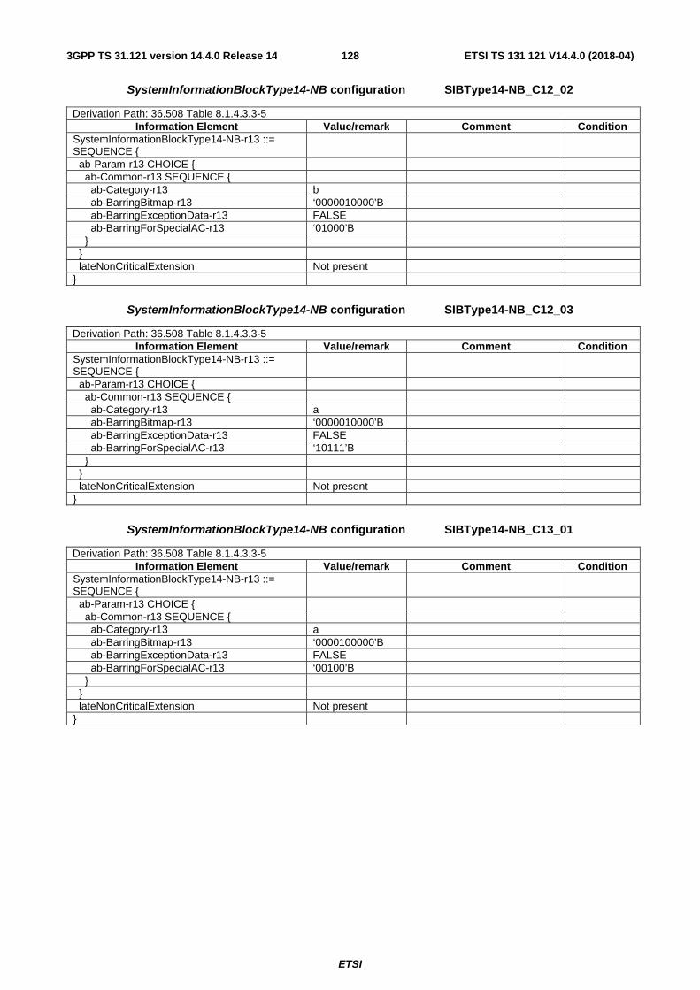
ETSI
ETSI TS 131 121 V14.4.0 (2018-04)1283GPP TS 31.121 version 14.4.0 Release 14
SystemInformationBlockType14-NB configuration SIBType14-NB_C12_02
Derivation Path: 36.508 Table 8.1.4.3.3-5 Information Element Value/remark Comment Condition
SystemInformationBlockType14-NB-r13 ::= SEQUENCE {
ab-Param-r13 CHOICE { ab-Common-r13 SEQUENCE { ab-Category-r13 b ab-BarringBitmap-r13 ‘0000010000’B ab-BarringExceptionData-r13 FALSE ab-BarringForSpecialAC-r13 ‘01000’B } } lateNonCriticalExtension Not present }
SystemInformationBlockType14-NB configuration SIBType14-NB_C12_03
Derivation Path: 36.508 Table 8.1.4.3.3-5 Information Element Value/remark Comment Condition
SystemInformationBlockType14-NB-r13 ::= SEQUENCE {
ab-Param-r13 CHOICE { ab-Common-r13 SEQUENCE { ab-Category-r13 a ab-BarringBitmap-r13 ‘0000010000’B ab-BarringExceptionData-r13 FALSE ab-BarringForSpecialAC-r13 ‘10111’B } } lateNonCriticalExtension Not present }
SystemInformationBlockType14-NB configuration SIBType14-NB_C13_01
Derivation Path: 36.508 Table 8.1.4.3.3-5 Information Element Value/remark Comment Condition
SystemInformationBlockType14-NB-r13 ::= SEQUENCE {
ab-Param-r13 CHOICE { ab-Common-r13 SEQUENCE { ab-Category-r13 a ab-BarringBitmap-r13 ‘0000100000’B ab-BarringExceptionData-r13 FALSE ab-BarringForSpecialAC-r13 ‘00100’B } } lateNonCriticalExtension Not present }

ETSI
ETSI TS 131 121 V14.4.0 (2018-04)1293GPP TS 31.121 version 14.4.0 Release 14
SystemInformationBlockType14-NB configuration SIBType14-NB_C13_02
Derivation Path: 36.508 Table 8.1.4.3.3-5 Information Element Value/remark Comment Condition
SystemInformationBlockType14-NB-r13 ::= SEQUENCE {
ab-Param-r13 CHOICE { ab-Common-r13 SEQUENCE { ab-Category-r13 b ab-BarringBitmap-r13 ‘0000100000’B ab-BarringExceptionData-r13 FALSE ab-BarringForSpecialAC-r13 ‘00100’B } } lateNonCriticalExtension Not present }
SystemInformationBlockType14-NB configuration SIBType14-NB_C13_03
Derivation Path: 36.508 Table 8.1.4.3.3-5 Information Element Value/remark Comment Condition
SystemInformationBlockType14-NB-r13 ::= SEQUENCE {
ab-Param-r13 CHOICE { ab-Common-r13 SEQUENCE { ab-Category-r13 a ab-BarringBitmap-r13 ‘0000100000’B ab-BarringExceptionData-r13 FALSE ab-BarringForSpecialAC-r13 ‘11011’B } } lateNonCriticalExtension Not present }
SystemInformationBlockType14-NB configuration SIBType14-NB_C14_01
Derivation Path: 36.508 Table 8.1.4.3.3-5 Information Element Value/remark Comment Condition
SystemInformationBlockType14-NB-r13 ::= SEQUENCE {
ab-Param-r13 CHOICE { ab-Common-r13 SEQUENCE { ab-Category-r13 a ab-BarringBitmap-r13 ‘0000000001’B ab-BarringExceptionData-r13 FALSE ab-BarringForSpecialAC-r13 ‘00010’B } } lateNonCriticalExtension Not present }

ETSI
ETSI TS 131 121 V14.4.0 (2018-04)1303GPP TS 31.121 version 14.4.0 Release 14
SystemInformationBlockType14-NB configuration SIBType14-NB_C14_02
Derivation Path: 36.508 Table 8.1.4.3.3-5 Information Element Value/remark Comment Condition
SystemInformationBlockType14-NB-r13 ::= SEQUENCE {
ab-Param-r13 CHOICE { ab-Common-r13 SEQUENCE { ab-Category-r13 b ab-BarringBitmap-r13 ‘0000000001’B ab-BarringExceptionData-r13 FALSE ab-BarringForSpecialAC-r13 ‘00010’B } } lateNonCriticalExtension Not present }
SystemInformationBlockType14-NB configuration SIBType14-NB_C14_03
Derivation Path: 36.508 Table 8.1.4.3.3-5 Information Element Value/remark Comment Condition
SystemInformationBlockType14-NB-r13 ::= SEQUENCE {
ab-Param-r13 CHOICE { ab-Common-r13 SEQUENCE { ab-Category-r13 a ab-BarringBitmap-r13 ‘0000000001’B ab-BarringExceptionData-r13 FALSE ab-BarringForSpecialAC-r13 ‘11101’B } } lateNonCriticalExtension Not present }
SystemInformationBlockType14-NB configuration SIBType14-NB_C15_01
Derivation Path: 36.508 Table 8.1.4.3.3-5 Information Element Value/remark Comment Condition
SystemInformationBlockType14-NB-r13 ::= SEQUENCE {
ab-Param-r13 CHOICE { ab-Common-r13 SEQUENCE { ab-Category-r13 a ab-BarringBitmap-r13 ‘1000000000’B ab-BarringExceptionData-r13 FALSE ab-BarringForSpecialAC-r13 ‘00001’B } } lateNonCriticalExtension Not present }
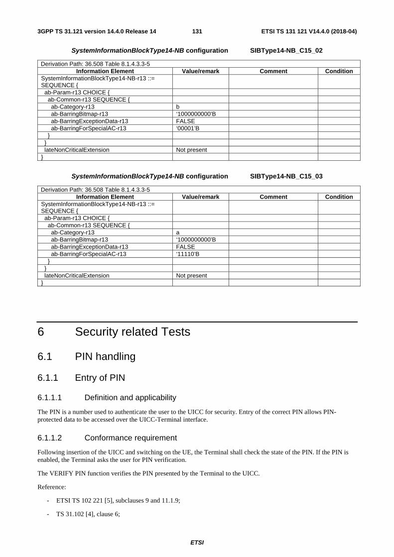
ETSI
ETSI TS 131 121 V14.4.0 (2018-04)1313GPP TS 31.121 version 14.4.0 Release 14
SystemInformationBlockType14-NB configuration SIBType14-NB_C15_02
Derivation Path: 36.508 Table 8.1.4.3.3-5 Information Element Value/remark Comment Condition
SystemInformationBlockType14-NB-r13 ::= SEQUENCE {
ab-Param-r13 CHOICE { ab-Common-r13 SEQUENCE { ab-Category-r13 b ab-BarringBitmap-r13 ‘1000000000’B ab-BarringExceptionData-r13 FALSE ab-BarringForSpecialAC-r13 ‘00001’B } } lateNonCriticalExtension Not present }
SystemInformationBlockType14-NB configuration SIBType14-NB_C15_03
Derivation Path: 36.508 Table 8.1.4.3.3-5 Information Element Value/remark Comment Condition
SystemInformationBlockType14-NB-r13 ::= SEQUENCE {
ab-Param-r13 CHOICE { ab-Common-r13 SEQUENCE { ab-Category-r13 a ab-BarringBitmap-r13 ‘1000000000’B ab-BarringExceptionData-r13 FALSE ab-BarringForSpecialAC-r13 ‘11110’B } } lateNonCriticalExtension Not present }
6 Security related Tests
6.1 PIN handling
6.1.1 Entry of PIN
6.1.1.1 Definition and applicability
The PIN is a number used to authenticate the user to the UICC for security. Entry of the correct PIN allows PIN-protected data to be accessed over the UICC-Terminal interface.
6.1.1.2 Conformance requirement
Following insertion of the UICC and switching on the UE, the Terminal shall check the state of the PIN. If the PIN is enabled, the Terminal asks the user for PIN verification.
The VERIFY PIN function verifies the PIN presented by the Terminal to the UICC.
Reference:
- ETSI TS 102 221 [5], subclauses 9 and 11.1.9;
- TS 31.102 [4], clause 6;
ETSI
ETSI TS 131 121 V14.4.0 (2018-04)1323GPP TS 31.121 version 14.4.0 Release 14
- TS 22.030 [12], subclause 6.6.1.
6.1.1.3 Test purpose
1) To verify that the PIN verification procedure is performed by the Terminal correctly.
2) To verify that the basic public MMI string is supported.
6.1.1.4 Method of test
6.1.1.4.1 Initial conditions
The Terminal is connected to a UICC or UICC simulator with the PIN enabled, and powered off.
The default UICC is used.
6.1.1.4.2 Procedure
a) The Terminal is powered on.
b) When the UE is in the "PIN check" mode, the sequence "2468#" shall be entered.
6.1.1.5 Acceptance criteria
1) After step b) the Terminal shall send a VERIFY PIN command to the UICC, with parameter P2 = "01".
2) After step b) the UE shall give an indication "OK", following a successful execution of the command.
6.1.2 Change of PIN
6.1.2.1 Definition and applicability
The PIN may be changed by the user, by entering the old and new PIN. The length of the PIN is between 4 and 8 digits.
6.1.2.2 Conformance requirement
The Terminal shall support the change of PIN procedure as defined in ETSI TS 102 221 [5], subclause 11.1.10.
Reference:
- ETSI TS 102 221 [5], subclauses 9 and 11.1.10;
- TS 31.102 [4], clause 6;
- TS 22.030 [12], subclause 6.6.2.
6.1.2.3 Test purpose
1) To verify that the PIN substitution procedure is performed correctly by the Terminal.
2) To verify that the basic public MMI string is supported.
6.1.2.4 Method of test
6.1.2.4.1 Initial conditions
The Terminal is connected to a UICC or UICC simulator with the PIN enabled.
The default UICC is used.
ETSI
ETSI TS 131 121 V14.4.0 (2018-04)1333GPP TS 31.121 version 14.4.0 Release 14
The Terminal is powered-on, with the correct PIN entered.
6.1.2.4.2 Procedure
a) Enter "**04*2468*01234567*01234567#" or initiate an equivalent MMI dependent procedure to change the PIN from '2468' to '01234567'.
b) The UE is switched off and on.
c) When the UE is in the "PIN check" mode, the sequence "2468#" shall be entered.
d) The UE is switched off and on.
e) When the UE is in the "PIN-check", mode the sequence "01234567#" shall be entered.
6.1.2.5 Acceptance criteria
1) After step a), the Terminal shall send a CHANGE PIN command to the UICC, with the parameter P2 set to "01".
2) Following the successful execution of the command, the UE shall give an indication that the new PIN is accepted.
3) After step c), the UE shall give an indication that the entered PIN is not accepted.
4) After step e), the UE shall give an indication "OK".
6.1.3 Unblock PIN
6.1.3.1 Definition and applicability
After three consecutive wrong entries of the PIN, the PIN shall become blocked. The Unblock PIN command is used to unblock the PIN. This function may be performed whether or not the PIN is blocked.
6.1.3.2 Conformance requirement
The Terminal shall support the Unblock PIN command, as defined in ETSI TS 102 221 [5], subclause 11.1.13.
Reference:
- ETSI TS 102 221 [5], subclause 11.1.13;
- TS 31.102 [4], clause 6;
- TS 22.030 [12], subclause 6.6.3.
6.1.3.3 Test purpose
1) To verify that the PIN unblocking procedure is performed correctly.
2) To verify that the basic public MMI string is supported.
6.1.3.4 Method of test
6.1.3.4.1 Initial conditions
The Terminal is connected to the UICC simulator.
The default UICC is used.
6.1.3.4.2 Procedure
Sequence A:

ETSI
ETSI TS 131 121 V14.4.0 (2018-04)1343GPP TS 31.121 version 14.4.0 Release 14
a) The Terminal is powered on and the correct PIN is entered.
b) Enter "**05*13243546*1234*1234#"
c) The Terminal is powered off and on.
d) Enter the new PIN: "1234#".
e) The Terminal is powered off and on.
f) Enter a wrong PIN three times.
g) Enter "**05*13243546*2468*2468#".
h) The Terminal is powered off and on.
i) Enter the new PIN: "2468#".
Sequence B:
a) The Terminal is powered on.
b) Enter a wrong PIN three times.
c) The user shall initiate a MMI dependent procedure to unblock the PIN with unblock code '13243546' and a new PIN '2468'.
d) The Terminal is powered off and on.
e) Enter the new PIN: "2468#".
6.1.3.5 Acceptance criteria
Sequence A:
1) After step b), the Terminal shall send an UNBLOCK PIN command to the UICC, with parameter P2 = "01".
2) After step d), the Terminal shall indicate that the PIN has been accepted.
3) After step f), the Terminal shall indicate that the PIN has been blocked.
4) After step g), the Terminal shall send an UNBLOCK PIN command to the UICC, with parameter P2 = "01".
5) After step i), the Terminal shall indicate that the PIN has been accepted.
Sequence B:
1) After step b), the Terminal shall indicate that the PIN has been blocked.
2) After step c), the Terminal shall send an UNBLOCK PIN command to the UICC, with parameter P2 = "01".
3) After step e), the Terminal shall indicate that the PIN has been accepted.
6.1.4 Entry of PIN2
6.1.4.1 Definition and applicability
The PIN2 is a number used to authenticate the user to the UICC for security. Entry of the correct PIN2 allows PIN2-protected data to be accessed over the UICC-Terminal interface.

ETSI
ETSI TS 131 121 V14.4.0 (2018-04)1353GPP TS 31.121 version 14.4.0 Release 14
6.1.4.2 Conformance requirement
Before allowing the access to PIN2 protected data, the Terminal shall ask the user for PIN2 verification. Only after presenting the PIN2, the user shall get access to these data.
The VERIFY PIN function verifies the PIN2 presented by the Terminal to the UICC.
Reference:
- ETSI TS 102 221 [5], subclauses 9 and 11.1.9;
- TS 31.102 [4], clause 6;
- TS 22.030 [12], subclause 6.6.1.
6.1.4.3 Test purpose
1) To verify that the PIN2 verification procedure is performed by the Terminal correctly.
2) To verify that the basic public MMI string is supported.
6.1.4.4 Method of test
6.1.4.4.1 Initial conditions
The Terminal is connected to a UICC or UICC simulator with the PIN enabled, and powered off.
The default UICC is used.
NOTE: To perform the UPDATE FDN data (as described in the procedure below), the default FDN UICC may be used.
6.1.4.4.2 Procedure
a) The Terminal is powered on and the correct PIN is entered.
b) The access to a PIN2 protected data field shall be performed (e.g. UPDATE FDN)
c) When the UE is in the "PIN2 check" mode, the sequence "3579#" shall be entered.
6.1.4.5 Acceptance criteria
1) After step c) the Terminal shall send a VERIFY PIN command to the UICC, with parameter P2 = "81".
2) After step c) the UE shall give an indication "OK", following a successful execution of the command.
6.1.5 Change of PIN2
6.1.5.1 Definition and applicability
The PIN2 may be changed by the user, by entering the old and new PIN2. The length of the PIN2 is between 4 and 8 digits.
6.1.5.2 Conformance requirement
The Terminal shall support the change of PIN2 procedure as defined in ETSI TS 102 221 [5], subclause 11.1.10.
Reference:
- ETSI TS 102 221 [5], subclauses 9 and 11.1.10;
- TS 31.102 [4], clause 6;

ETSI
ETSI TS 131 121 V14.4.0 (2018-04)1363GPP TS 31.121 version 14.4.0 Release 14
- TS 22.030 [12], subclause 6.6.2.
6.1.5.3 Test purpose
1) To verify that the PIN2 substitution procedure is performed correctly by the Terminal.
2) To verify that the basic public MMI string is supported.
6.1.5.4 Method of test
6.1.5.4.1 Initial conditions
The Terminal is connected to a UICC or UICC simulator with the PIN2 enabled.
The default UICC is used.
NOTE: To perform the UPDATE FDN data (as described in the procedure below), the default FDN UICC may be used.
The Terminal is powered-on, with the correct PIN entered.
6.1.5.4.2 Procedure
a) Enter "**042*3579*12345678*12345678#" or initiate an equivalent MMI dependent procedure to change PIN2 from '3579' to '12345678'.
b) The UE is switched off and on and the correct PIN is entered.
c) The access to a PIN2 protected data field shall be performed (e.g. UPDATE FDN).
d) When the UE is in the "PIN2 check" mode, the sequence "3579#" shall be entered.
e) The UE is switched off and on and the correct PIN is entered.
f) The access to a PIN2 protected data field shall be performed (e.g. UPDATE FDN).
g) When the UE is in the "PIN2 check", mode the sequence "12345678#" shall be entered.
6.1.5.5 Acceptance criteria
1) After step a), the Terminal shall send a CHANGE PIN2 command to the UICC, with the parameter P2 set to "81".
2) Following the successful execution of the command, the UE shall give an indication that the new PIN2 is accepted.
3) After step d), the UE shall give an indication that the entered PIN2 is not accepted.
4) After step g), the UE shall give an indication "OK".
6.1.6 Unblock PIN2
6.1.6.1 Definition and applicability
After three consecutive wrong entries of the PIN2, the PIN2 shall become blocked. The Unblock PIN2 command is used to unblock the PIN2. This function may be performed whether or not the PIN2 is blocked.
6.1.6.2 Conformance requirement
The Terminal shall support the Unblock PIN2 command, as defined in ETSI TS 102 221 [5], subclause 11.1.13.
Reference:

ETSI
ETSI TS 131 121 V14.4.0 (2018-04)1373GPP TS 31.121 version 14.4.0 Release 14
- ETSI TS 102 221 [5], subclauses 9 and 11.1.13;
- TS 31.102 [4], clause 6;
- TS 22.030 [12], subclause 6.6.3.
6.1.6.3 Test purpose
1) To verify that the PIN2 unblocking procedure is performed correctly.
2) To verify that the basic public MMI string is supported.
6.1.6.4 Method of test
6.1.6.4.1 Initial conditions
The Terminal is connected to the UICC simulator.
The default UICC is used.
NOTE: To perform the UPDATE FDN data (as described in the procedure below), the default FDN UICC may be used.
6.1.6.4.2 Procedure
Sequence A:
a) The Terminal is powered on and the correct PIN is entered.
b) Enter "**052*08978675*1234*1234#"
c) The Terminal is powered off and on and the correct PIN is entered.
d) The access to a PIN2 protected data field shall be performed (e.g. UPDATE FDN).
e) Enter the new PIN2: "1234#".
f) The Terminal is powered off and on and the correct PIN is entered.
g) The access to a PIN2 protected data field shall be performed (e.g. UPDATE FDN).
h) Enter a wrong PIN2 three times.
i) Enter "**052*08978675*3579*3579#".
j) The Terminal is powered off and on and the correct PIN is entered.
k) The access to a PIN2 protected data field shall be performed (e.g. UPDATE FDN).
l) Enter the new PIN2: "3579#".
Sequence B:
a) The Terminal is powered on.
b) Enter a wrong PIN2 three times.
c) The user shall initiate a MMI dependent procedure to unblock the PIN2 with unblock code '08978675' and a new PIN '3579'.
d) The Terminal is powered off and on and the correct PIN is entered.
e) The access to a PIN2 protected data field shall be performed (e.g. UPDATE FDN).
f) Enter the new PIN2: "3579#".

ETSI
ETSI TS 131 121 V14.4.0 (2018-04)1383GPP TS 31.121 version 14.4.0 Release 14
6.1.6.5 Acceptance criterias
Sequence A:
1) After step b), the Terminal shall send an UNBLOCK PIN command to the UICC, with parameter P2 = "81".
2) After step e), the Terminal shall indicate that the PIN2 has been accepted.
3) After step h), the Terminal shall indicate that the PIN2 has been blocked.
4) After step i), the Terminal shall send an UNBLOCK PIN command to the UICC, with parameter P2 = "81".
5) After step l), the Terminal shall indicate that the PIN2 has been accepted.
Sequence B:
1) After step b), the Terminal shall indicate that the PIN2 has been blocked.
2) After step c), the Terminal shall send an UNBLOCK PIN command to the UICC, with parameter P2 = "81".
3) After step f), the Terminal shall indicate that the PIN2 has been accepted.
6.1.7 Replacement of PIN
6.1.7.1 Definition and applicability
The Universal PIN may be used to replace a PIN used to authenticate the user to the UICC for security. In this case entry of the correct Universal PIN allows PIN-protected data to be accessed over the UICC-Terminal interface. ETSI TS 102 221 [5] defines the range of "01" to "08" as key reference of the PIN on a multi-verification capable UICC.
6.1.7.2 Conformance requirement
The Terminal shall support the usage of the Universal PIN as replacement PIN and the replacement procedure as defined in ETSI TS 102 221 [5], subclause 11.1.11, as well as the procedure to disable the replacement defined in ETSI TS 102 221 [5], subclause 11.1.12.
Reference:
- ETSI TS 102 221 [5], subclauses 9, 11.1.11 and 11.1.12;
- TS 31.102 [4], clause 6.
6.1.7.3 Test purpose
1) To verify that the PIN replacement is supported by the Terminal correctly.
2) To verify that the PIN replacement procedure is performed by the Terminal correctly.
3) To verify that the procedure to disable the PIN replacement is performed by the Terminal correctly.
6.1.7.4 Method of test
6.1.7.4.1 Initial conditions
The Terminal is connected to the UICC simulator with the PIN enabled, and powered off.
The default UICC is used.
6.1.7.4.2 Procedure
a) The Terminal is powered on.

ETSI
ETSI TS 131 121 V14.4.0 (2018-04)1393GPP TS 31.121 version 14.4.0 Release 14
b) When the Terminal is in the "PIN check" mode, the sequence "2468#" shall be entered.
c) The user shall initiate an MMI dependent procedure to replace the PIN by the Universal PIN.
d) The Terminal is powered off and on and when the Terminal is in "PIN check" mode the sequence "2468#" shall be entered.
e) The correct Universal PIN is entered.
f) The user shall initiate an MMI dependent procedure to disable the replacement of the PIN by the Universal PIN.
g) The Terminal is powered off and on and when the Terminal is in "PIN check" mode the sequence "2839#" shall be entered.
h) The correct PIN is entered.
6.1.7.5 Acceptance criteria
1) After step b) the Terminal shall send a VERIFY PIN command to the UICC, with parameter P2 = "01".
2) After step c), the Terminal shall send a DISABLE PIN command to the UICC, with parameter P1="91" and P2 = "01".
3) After step d) the Terminal shall send a VERIFY PIN command to the UICC, with parameter P2 = "11" and after unsuccessful execution of the command the Terminal shall indicate that the PIN has not been accepted.
4) After step e) the Terminal shall send a VERIFY PIN command to the UICC, with parameter P2 = "11" and after successful execution of the command the Terminal shall indicate that the PIN has been accepted.
5) After step f), the Terminal shall send an ENABLE PIN command to the UICC, with parameter P2 = "01".
6) After step g) the Terminal shall send a VERIFY PIN command to the UICC, with parameter P2 = "01" and after unsuccessful execution of the command the Terminal shall indicate that the PIN has not been accepted.
7) After step e) the Terminal shall send a VERIFY PIN command to the UICC, with parameter P2 = "01" and after successful execution of the command the Terminal shall indicate that the PIN has been accepted.
6.1.8 Change of Universal PIN
6.1.8.1 Definition and applicability
The Universal PIN may be changed by the user, by entering the old and new Universal PIN. The length of the Universal PIN is between 4 and 8 digits.
6.1.8.2 Conformance requirement
The Terminal shall support the change of PIN procedure as defined in ETSI TS 102 221 [5], subclause 11.1.10.
Reference:
- ETSI TS 102 221 [5], subclauses 9 and 11.1.10;
- TS 31.102 [4], clause 6.
6.1.8.3 Test purpose
To verify that the PIN substitution procedure is performed correctly by the Terminal.

ETSI
ETSI TS 131 121 V14.4.0 (2018-04)1403GPP TS 31.121 version 14.4.0 Release 14
6.1.8.4 Method of test
6.1.8.4.1 Initial conditions
The Terminal is connected to a UICC or UICC simulator with the PIN enabled.
The default UICC is used with the following exception:
- The Universal PIN is used as a replacement of the PIN.
The Terminal is powered-on, with the correct Universal PIN entered.
6.1.8.4.2 Procedure
a) The user shall initiate an MMI dependent procedure to change the Universal PIN to "01234567".
b) The UE is switched off and on.
c) When the UE is in the "PIN check" mode, the sequence "2839#" shall be entered.
d) The UE is switched off and on.
e) When the UE is in the "PIN check", mode the sequence "01234567#" shall be entered.
6.1.8.5 Acceptance criteria
1) After step a), the Terminal shall send a CHANGE PIN command to the UICC, with the parameter P2 set to "11".
2) Following the successful execution of the command, the UE shall give an indication that the new (Universal) PIN is accepted.
3) After step c), the UE shall give an indication that the entered (Universal) PIN is not accepted.
4) After step e), the UE shall give an indication "OK".
6.1.9 Unblock Universal PIN
6.1.9.1 Definition and applicability
After three consecutive wrong entries of the PIN, the PIN shall become blocked. The Unblock PIN command is used to unblock the PIN. This function may be performed whether or not the PIN is blocked.
6.1.9.2 Conformance requirement
The Terminal shall support the Unblock PIN command, as defined in ETSI TS 102 221 [5], subclause 11.1.13.
Reference:
- ETSI TS 102 221 [5], subclause 11.1.13;
- TS 31.102 [4], clause 6.
6.1.9.3 Test purpose
To verify that the PIN unblocking procedure is performed correctly.
6.1.9.4 Method of test
6.1.9.4.1 Initial conditions
The Terminal is connected to the UICC simulator.

ETSI
ETSI TS 131 121 V14.4.0 (2018-04)1413GPP TS 31.121 version 14.4.0 Release 14
The default UICC is used.
6.1.9.4.2 Procedure
a) The Terminal is powered on and the correct PIN is entered.
b) The user shall initiate an MMI dependent procedure to unblock the Universal PIN and set the new Universal PIN value to "1234"
c) The Terminal is powered off and on.
d) Enter the new PIN: "1234#".
e) The Terminal is powered off and on.
f) Enter a wrong PIN three times.
g) The user shall initiate an MMI dependent procedure to unblock the Universal PIN and set the new Universal PIN value to "2839".
h) The Terminal is powered off and on.
i) Enter the new PIN: "2839#".
6.1.9.5 Acceptance criteria
1) After step b), the Terminal shall send an UNBLOCK PIN command to the UICC, with parameter P2 = "11".
2) After step d), the Terminal shall indicate that the (Universal) PIN has been accepted.
3) After step f), the Terminal shall indicate that the (Universal) PIN has been blocked.
4) After step g), the Terminal shall send an UNBLOCK PIN command to the UICC, with parameter P2 = "11".
5) After step j), the Terminal shall indicate that the (Universal) PIN has been accepted.
6.1.10 Entry of PIN on multi-verification capable UICCs
6.1.10.1 Definition and applicability
The PIN is a number used to authenticate the user to the UICC for security. Entry of the correct PIN allows PIN-protected data to be accessed over the UICC-Terminal interface. ETSI TS 102 221 [5] defines the range of "01" to "08" as key reference of the PIN on a multi-verification capable UICC.
6.1.10.2 Conformance requirement
Following insertion of the UICC and switching on the UE, the Terminal shall check the state of the PIN. If the PIN is enabled, the Terminal asks the user for PIN verification.
The VERIFY PIN function verifies the PIN presented by the Terminal to the UICC.
Reference:
- ETSI TS 102 221 [5], subclauses 9 and 11.1.9;
- TS 31.102 [4], clause 6;
- TS 22.030 [12], subclause 6.6.1.
6.1.10.3 Test purpose
1) To verify that the PIN verification procedure is performed by the Terminal correctly.
2) To verify that the basic public MMI string is supported.

ETSI
ETSI TS 131 121 V14.4.0 (2018-04)1423GPP TS 31.121 version 14.4.0 Release 14
3) To verify that the Terminal supports key references in the range of "01" to "08" as PIN.
6.1.10.4 Method of test
6.1.10.4.1 Initial conditions
The Terminal is connected to the UICC simulator with the PIN enabled, and powered off.
The default UICC is used with the following exceptions:
The UICC shall be configured to use "07" as the key reference of the PIN and "87" as key reference of the PIN2 with the following values:
PIN
Key reference: 07
Logically: 8642
Coding: B1 B2 B3 B4 B5 B6 B7 B8 Hex 38 36 34 32 FF FF FF FF
Unblock PIN
Key reference 07
Logically: 64534231
Coding: B1 B2 B3 B4 B5 B6 B7 B8 Hex 36 34 35 33 34 32 33 31
PIN2
Key reference 87
Logically: 9753
Coding: B1 B2 B3 B4 B5 B6 B7 B8 Hex 39 37 35 33 FF FF FF FF
Unblock PIN2
Key reference 87
Logically: 57687980
Coding: B1 B2 B3 B4 B5 B6 B7 B8 Hex 35 37 36 38 37 39 38 30
6.1.10.4.2 Procedure
a) The Terminal is powered on.
b) When the UE is in the "PIN check" mode, the sequence "8642#" shall be entered.
6.1.10.5 Acceptance criteria
1) After step b) the Terminal shall send a VERIFY PIN command to the UICC, with parameter P2 = "07".
2) After step b) the UE shall give an indication "OK", following a successful execution of the command.

ETSI
ETSI TS 131 121 V14.4.0 (2018-04)1433GPP TS 31.121 version 14.4.0 Release 14
6.1.11 Change of PIN on multi-verification capable UICCs
6.1.11.1 Definition and applicability
The PIN may be changed by the user, by entering the old and new PIN. The length of the PIN is between 4 and 8 digits. ETSI TS 102 221 [5] defines the range of "01" to "08" as key reference of the PIN on a multi-verification capable UICC.
6.1.11.2 Conformance requirement
The Terminal shall support the change of PIN procedure as defined in TS 102 221 [5], subclause 11.1.10.
Reference:
- ETSI TS 102 221 [5], subclauses 9 and 11.1.10;
- TS 31.102 [4], clause 6;
- TS 22.030 [12], subclause 6.6.2.
6.1.11.3 Test purpose
1) To verify that the PIN substitution procedure is performed correctly by the Terminal.
2) To verify that the basic public MMI string is supported.
3) To verify that the Terminal supports key references in the range of "01" to "08" as PIN.
6.1.11.4 Method of test
6.1.11.4.1 Initial conditions
The Terminal is connected to the UICC simulator with the PIN enabled.
The default UICC is used with the following exceptions:
The UICC shall be configured to use "07" as the reference of the PIN and "87" as reference of the PIN2 with the following values:
PIN
Key reference: 07
Logically: 8642
Coding: B1 B2 B3 B4 B5 B6 B7 B8 Hex 38 36 34 32 FF FF FF FF
Unblock PIN
Key reference 07
Logically: 64534231
Coding: B1 B2 B3 B4 B5 B6 B7 B8 Hex 36 34 35 33 34 32 33 31
PIN2
Key reference 87

ETSI
ETSI TS 131 121 V14.4.0 (2018-04)1443GPP TS 31.121 version 14.4.0 Release 14
Logically: 9753
Coding: B1 B2 B3 B4 B5 B6 B7 B8 Hex 39 37 35 33 FF FF FF FF
Unblock PIN2
Key reference 87
Logically: 57687980
Coding: B1 B2 B3 B4 B5 B6 B7 B8 Hex 35 37 36 38 37 39 38 30
The Terminal is powered-on, with the correct PIN entered.
6.1.11.4.2 Procedure
a) Enter "**04*8642*01234567*01234567#" or initiate an equivalent MMI dependent procedure to change the PIN from '8642' to '01234567'..
b) The UE is switched off and on.
c) When the UE is in the "PIN check" mode, the sequence "8642#" shall be entered.
d) The UE is switched off and on.
e) When the UE is in the "PIN check", mode the sequence "01234567#" shall be entered.
6.1.11.5 Acceptance criteria
1) After step a), the Terminal shall send a CHANGE PIN command to the UICC, with the parameter P2 set to "07".
2) Following the successful execution of the command, the UE shall give an indication that the new PIN is accepted.
3) After step c), the UE shall give an indication that the entered PIN is not accepted.
3) After step e), the UE shall give an indication "OK".
6.1.12 Unblock PIN on multi-verification capable UICCs
6.1.12.1 Definition and applicability
After three consecutive wrong entries of the PIN, the PIN shall become blocked. The Unblock PIN command is used to unblock the PIN. This function may be performed whether or not the PIN is blocked. ETSI TS 102 221 [5] defines the range of "01" to "08" as key reference of the PIN on a multi-verification capable UICC.
6.1.12.2 Conformance requirement
The Terminal shall support the Unblock PIN command, as defined in ETSI TS 102 221 [5], subclause 11.1.13.
Reference:
- ETSI TS 102 221 [5], subclauses 9 and 11.1.13;
- TS 31.102 [4], clause 6;
- TS 22.030 [12], subclause 6.6.3.

ETSI
ETSI TS 131 121 V14.4.0 (2018-04)1453GPP TS 31.121 version 14.4.0 Release 14
6.1.12.3 Test purpose
1) To verify that the PIN unblocking procedure is performed correctly.
2) To verify that the basic public MMI string is supported.
3) To verify that the Terminal supports key references in the range of "01" to "08" as PIN.
6.1.12.4 Method of test
6.1.12.4.1 Initial conditions
The Terminal is connected to the UICC simulator.
The default UICC is used with the following exceptions:
The UICC shall be configured to use "07" as the reference of the PIN and "87" as reference of the PIN2 with the following values:
PIN
Key reference: 07
Logically: 8642
Coding: B1 B2 B3 B4 B5 B6 B7 B8 Hex 38 36 34 32 FF FF FF FF
Unblock PIN
Key reference 07
Logically: 64534231
Coding: B1 B2 B3 B4 B5 B6 B7 B8 Hex 36 34 35 33 34 32 33 31
PIN2
Key reference 87
Logically: 9753
Coding: B1 B2 B3 B4 B5 B6 B7 B8 Hex 39 37 35 33 FF FF FF FF
Unblock PIN2
Key reference 87
Logically: 57687980
Coding: B1 B2 B3 B4 B5 B6 B7 B8 Hex 35 37 36 38 37 39 38 30
6.1.12.4.2 Procedure
Sequence A:
a) The Terminal is powered on and the correct PIN is entered.
b) Enter "**05*64534231*1234*1234#"
ETSI
ETSI TS 131 121 V14.4.0 (2018-04)1463GPP TS 31.121 version 14.4.0 Release 14
c) The Terminal is powered off and on.
d) Enter the new PIN: "1234#".
e) The Terminal is powered off and on.
f) Enter a wrong PIN three times.
g) Enter "**05*64534231*8642*8642#".
h) The Terminal is powered off and on.
i) Enter the new PIN: "8642#".
Sequence B:
a) The Terminal is powered on.
b) Enter a wrong PIN three times.
c) The user shall initiate a MMI dependent procedure to unblock the PIN with unblock code '64534231' and a new PIN '8642'.
d) The Terminal is powered off and on.
e) Enter the new PIN: "8642#".
6.1.12.5 Acceptance criteria
Sequence A:
1) After step b), the Terminal shall send an UNBLOCK PIN command to the UICC, with parameter P2 = "07".
2) After step d), the Terminal shall indicate that the PIN has been accepted.
3) After step f), the Terminal shall indicate that the PIN has been blocked.
4) After step g), the Terminal shall send an UNBLOCK PIN command to the UICC, with parameter P2 = "07".
5) After step j), the Terminal shall indicate that the PIN has been accepted.
Sequence B:
1) After step b), the Terminal shall indicate that the PIN has been blocked.
2) After step c), the Terminal shall send an UNBLOCK PIN command to the UICC, with parameter P2 = "07".
3) After step e), the Terminal shall indicate that the PIN has been accepted.
6.1.13 Entry of PIN2 on multi-verification capable UICCs
6.1.13.1 Definition and applicability
The PIN2 is a number used to authenticate the user to the UICC for security. Entry of the correct PIN2 allows PIN2-protected data to be accessed over the UICC-Terminal interface. ETSI TS 102 221 [5] defines the range of "81" to "88" as key reference of the PIN2 on a multi-verification capable UICC.
6.1.13.2 Conformance requirement
Before allowing the access to PIN2 protected data, the Terminal shall ask the user for PIN2 verification. Only after presenting the PIN2, the user shall get access to these data.
The VERIFY PIN function verifies the PIN2 presented by the Terminal to the UICC.
Reference:

ETSI
ETSI TS 131 121 V14.4.0 (2018-04)1473GPP TS 31.121 version 14.4.0 Release 14
- ETSI TS 102 221 [5], 9 and subclause 11.1.9;
- TS 31.102 [4], clause 6;
- TS 22.030 [12], subclause 6.6.1.
6.1.13.3 Test purpose
1) To verify that the PIN2 verification procedure is performed by the Terminal correctly.
2) To verify that the basic public MMI string is supported.
3) To verify that the Terminal supports key references in the range of "81" to "88" as PIN2.
6.1.13.4 Method of test
6.1.13.4.1 Initial conditions
The Terminal is connected to the UICC simulator with the PIN enabled, and powered off.
The default UICC is used with the following exceptions:
The UICC shall be configured to use "07" as the reference of the PIN and "87" as reference of the PIN2 with the following values:
PIN
Key reference: 07
Logically: 8642
Coding: B1 B2 B3 B4 B5 B6 B7 B8 Hex 38 36 34 32 FF FF FF FF
Unblock PIN
Key reference 07
Logically: 64534231
Coding: B1 B2 B3 B4 B5 B6 B7 B8 Hex 36 34 35 33 34 32 33 31
PIN2
Key reference 87
Logically: 9753
Coding: B1 B2 B3 B4 B5 B6 B7 B8 Hex 39 37 35 33 FF FF FF FF
Unblock PIN2
Key reference 87
Logically: 57687980
Coding: B1 B2 B3 B4 B5 B6 B7 B8 Hex 35 37 36 38 37 39 38 30
ETSI
ETSI TS 131 121 V14.4.0 (2018-04)1483GPP TS 31.121 version 14.4.0 Release 14
NOTE: To perform the UPDATE FDN data (as described in the procedure below), the default FDN UICC may be used. In this case the above mentioned exceptions shall apply.
6.1.13.4.2 Procedure
a) The Terminal is powered on and the correct PIN is entered.
b) The access to a PIN2 protected data field shall be performed (e.g. UPDATE FDN)
c) When the UE is in the "PIN2 check" mode, the sequence "9753#" shall be entered.
6.1.13.5 Acceptance criteria
1) After step b) the Terminal shall send a VERIFY PIN command to the UICC, with parameter P2 = "87".
2) After step b) the UE shall give an indication "OK", following a successful execution of the command.
6.1.14 Change of PIN2 on multi-verification capable UICCs
6.1.14.1 Definition and applicability
The PIN2 may be changed by the user, by entering the old and new PIN2. The length of the PIN2 is between 4 and 8 digits. ETSI TS 102 221 [5] defines the range of "81" to "88" as key reference of the PIN2 on a multi-verification capable UICC.
6.1.14.2 Conformance requirement
The Terminal shall support the change of PIN2 procedure as defined in ETSI TS 102 221 [5], subclause 11.1.10.
Reference:
- ETSI TS 102 221 [5], subclauses 9 and 11.1.10;
- TS 31.102 [4], clause 6;
- TS 22.030 [12], subclause 6.6.2.
6.1.14.3 Test purpose
1) To verify that the PIN2 substitution procedure is performed correctly by the Terminal.
2) To verify that the basic public MMI string is supported.
3) To verify that the Terminal supports key references in the range of "81" to "88" as PIN2.
6.1.14.4 Method of test
6.1.14.4.1 Initial conditions
The Terminal is connected to the UICC simulator with the PIN2 enabled.
The default UICC is used with the following exceptions:
The UICC shall be configured to use "07" as the reference of the PIN and "87" as reference of the PIN2 with the following values:
PIN
Key reference: 07
Logically: 8642

ETSI
ETSI TS 131 121 V14.4.0 (2018-04)1493GPP TS 31.121 version 14.4.0 Release 14
Coding: B1 B2 B3 B4 B5 B6 B7 B8 Hex 38 36 34 32 FF FF FF FF
Unblock PIN
Key reference 07
Logically: 64534231
Coding: B1 B2 B3 B4 B5 B6 B7 B8 Hex 36 34 35 33 34 32 33 31
PIN2
Key reference 87
Logically: 9753
Coding: B1 B2 B3 B4 B5 B6 B7 B8 Hex 39 37 35 33 FF FF FF FF
Unblock PIN2
Key reference 87
Logically: 57687980
Coding: B1 B2 B3 B4 B5 B6 B7 B8 Hex 35 37 36 38 37 39 38 30
NOTE: To perform the UPDATE FDN data (as described in the procedure below), the default FDN UICC may be used. In this case the above mentioned exceptions shall apply.
The Terminal is powered-on, with the correct PIN entered.
6.1.14.4.2 Procedure
a) Enter "**042*9753*12345678*12345678#" or initiate an equivalent MMI dependent procedure to change PIN2 from '9753' to '12345678'.
b) The UE is switched off and on and the correct PIN is entered.
c) The access to a PIN2 protected data field shall be performed (e.g. UPDATE FDN).
d) When the UE is in the "PIN2 check" mode, the sequence "9753#" shall be entered.
e) The UE is switched off and on and the correct PIN is entered.
f) The access to a PIN2 protected data field shall be performed (e.g. UPDATE FDN).
g) When the UE is in the "PIN2-check", mode the sequence "12345678#" shall be entered.
6.1.14.5 Acceptance criteria
1) After step a), the Terminal shall send a CHANGE PIN2 command to the UICC, with the parameter P2 set to "87".
2) Following the successful execution of the command, the UE shall give an indication that the new PIN2 is accepted.
3) After step d), the UE shall give an indication that the entered PIN2 is not accepted.

ETSI
ETSI TS 131 121 V14.4.0 (2018-04)1503GPP TS 31.121 version 14.4.0 Release 14
3) After step g), the UE shall give an indication "OK".
6.1.15 Unblock PIN2 on multi-verification capable UICCs
6.1.15.1 Definition and applicability
After three consecutive wrong entries of the PIN2, the PIN2 shall become blocked. The Unblock PIN2 command is used to unblock the PIN2. This function may be performed whether or not the PIN2 is blocked. ETSI TS 102 221 [5] defines the range of "81" to "88" as key reference of the PIN2 on a multi-verification capable UICC.
6.1.15.2 Conformance requirement
The Terminal shall support the Unblock PIN2 command, as defined in ETSI TS 102 221 [5], subclause 11.1.13.
Reference:
- ETSI TS 102 221 [5],subclauses 9 and 11.1.13;
- TS 31.102 [4], clause 6;
- TS 22.030 [12], subclause 6.6.3.
6.1.15.3 Test purpose
1) To verify that the PIN2 unblocking procedure is performed correctly.
2) To verify that the basic public MMI string is supported.
3) To verify that the Terminal supports key references in the range of "81" to "88" as PIN2.
6.1.15.4 Method of test
6.1.15.4.1 Initial conditions
The Terminal is connected to the UICC simulator.
The default UICC is used with the following exceptions:
The UICC shall be configured to use "07" as the reference of the PIN and "87" as reference of the PIN2 with the following values:
PIN
Key reference: 07
Logically: 8642
Coding: B1 B2 B3 B4 B5 B6 B7 B8 Hex 38 36 34 32 FF FF FF FF
Unblock PIN
Key reference 07
Logically: 64534231
Coding: B1 B2 B3 B4 B5 B6 B7 B8 Hex 36 34 35 33 34 32 33 31
PIN2

ETSI
ETSI TS 131 121 V14.4.0 (2018-04)1513GPP TS 31.121 version 14.4.0 Release 14
Key reference 87
Logically: 9753
Coding: B1 B2 B3 B4 B5 B6 B7 B8 Hex 39 37 35 33 FF FF FF FF
Unblock PIN2
Key reference 87
Logically: 57687980
Coding: B1 B2 B3 B4 B5 B6 B7 B8 Hex 35 37 36 38 37 39 38 30
NOTE: To perform the UPDATE FDN data (as described in the procedure below), the default FDN UICC may be used. In this case the above mentioned exceptions shall apply.
6.1.15.4.2 Procedure
Sequence A:
a) The Terminal is powered on and the correct PIN is entered.
b) Enter "**052*57687980*1234*1234#"
c) The Terminal is powered off and on and the correct PIN is entered.
d) The access to a PIN2 protected data field shall be performed (e.g. UPDATE FDN).
e) Enter the new PIN2: "1234#".
f) The Terminal is powered off and on and the correct PIN is entered.
g) The access to a PIN2 protected data field shall be performed (e.g. UPDATE FDN).
h) Enter a wrong PIN2 three times.
i) Enter "**052*57687980*9753*9753#".
j) The Terminal is powered off and on and the correct PIN is entered.
k) The access to a PIN2 protected data field shall be performed (e.g. UPDATE FDN).
l) Enter the new PIN2: "9753#".
Sequence B:
a) The Terminal is powered on .
b) Enter a wrong PIN2 three times.
c) The user shall initiate a MMI dependent procedure to unblock the PIN2 with unblock code '57687980' and a new PIN2 '9753'.
d) The Terminal is powered off and on and the correct PIN is entered.
e) The access to a PIN2 protected data field shall be performed (e.g. UPDATE FDN).
f) Enter the new PIN2: "9753#".

ETSI
ETSI TS 131 121 V14.4.0 (2018-04)1523GPP TS 31.121 version 14.4.0 Release 14
6.1.15.5 Acceptance criterias
Sequence A:
1) After step b), the Terminal shall send an UNBLOCK PIN command to the UICC, with parameter P2 = "87".
2) After step e), the Terminal shall indicate that the PIN2 has been accepted.
3) After step h), the Terminal shall indicate that the PIN2 has been blocked.
4) After step i), the Terminal shall send an UNBLOCK PIN command to the UICC, with parameter P2 = "87".
5) After step l), the Terminal shall indicate that the PIN2 has been accepted.
Sequence B:
1) After step b), the Terminal shall indicate that the PIN2 has been blocked.
2) After step c), the Terminal shall send an UNBLOCK PIN command to the UICC, with parameter P2 = "87".
3) After step f), the Terminal shall indicate that the PIN2 has been accepted.
6.1.16 Replacement of PIN with key reference "07"
6.1.16.1 Definition and applicability
The Universal PIN may be used to replace a PIN used to authenticate the user to the UICC for security. In this case entry of the correct Universal PIN allows PIN-protected data to be accessed over the UICC-Terminal interface.
6.1.16.2 Conformance requirement
The Terminal shall support the usage of the Universal PIN as replacement PIN and the replacement procedure as defined in ETSI TS 102 221 [5], subclause 11.1.11, as well as the procedure to disable the replacement defined in ETSI TS 102 221 [5], subclause 11.1.12.
Reference:
- ETSI TS 102 221 [5], subclauses 9, 11.1.11 and 11.1.12;
- TS 31.102 [4], clause 6.
6.1.16.3 Test purpose
1) To verify that the PIN replacement is supported by the Terminal correctly.
2) To verify that the PIN replacement procedure is performed by the Terminal correctly.
3) To verify that the procedure to disable the PIN replacement is performed by the Terminal correctly.
4) To verify that the Terminal supports key references in the range of "01" to "08" as PIN.
6.1.16.4 Method of test
6.1.16.4.1 Initial conditions
The Terminal is connected to the UICC simulator with the PIN enabled, and powered off.
The default UICC is used with the following exceptions:
The UICC shall be configured to use "07" as the reference of the PIN and "87" as reference of the PIN2 with the following values:
PIN
ETSI
ETSI TS 131 121 V14.4.0 (2018-04)1533GPP TS 31.121 version 14.4.0 Release 14
Key reference: 07
Logically: 8642
Coding: B1 B2 B3 B4 B5 B6 B7 B8 Hex 38 36 34 32 FF FF FF FF
Unblock PIN
Key reference 07
Logically: 64534231
Coding: B1 B2 B3 B4 B5 B6 B7 B8 Hex 36 34 35 33 34 32 33 31
PIN2
Key reference 87
Logically: 9753
Coding: B1 B2 B3 B4 B5 B6 B7 B8 Hex 39 37 35 33 FF FF FF FF
Unblock PIN2
Key reference 87
Logically: 57687980
Coding: B1 B2 B3 B4 B5 B6 B7 B8 Hex 35 37 36 38 37 39 38 30
6.1.16.4.2 Procedure
a) The Terminal is powered on.
b) When the Terminal is in the "PIN check" mode, the sequence "8642#" shall be entered.
c) The user shall initiate an MMI dependent procedure to replace the PIN by the Universal PIN.
d) The Terminal is powered off and on and when the Terminal is in "PIN check" mode the sequence "8642#" shall be entered.
e) The correct Universal PIN is entered.
f) The user shall initiate an MMI dependent procedure to disable the replacement of the PIN by the Universal PIN.
g) The Terminal is powered off and on and when the Terminal is in "PIN check" mode the sequence "2839#" shall be entered.
h) The correct PIN is entered.
6.1.16.5 Acceptance criteria
1) After step b) the Terminal shall send a VERIFY PIN command to the UICC, with parameter P2 = "07".
2) After step c), the Terminal shall send a DISABLE PIN command to the UICC, with parameter P1="91" and P2 = "07".

ETSI
ETSI TS 131 121 V14.4.0 (2018-04)1543GPP TS 31.121 version 14.4.0 Release 14
3) After step d) the Terminal shall send a VERIFY PIN command to the UICC, with parameter P2 = "11" and after unsuccessful execution of the command the Terminal shall indicate that the PIN has not been accepted.
4) After step e) the Terminal shall send a VERIFY PIN command to the UICC, with parameter P2 = "11" and after successful execution of the command the Terminal shall indicate that the PIN has been accepted.
5) After step f), the Terminal shall send an ENABLE PIN command to the UICC, with parameter P2 = "07".
6) After step g) the Terminal shall send a VERIFY PIN command to the UICC, with parameter P2 = "07" and after unsuccessful execution of the command the Terminal shall indicate that the PIN has not been accepted.
7) After step h) the Terminal shall send a VERIFY PIN command to the UICC, with parameter P2 = "07" and after successful execution of the command the Terminal shall indicate that the PIN has been accepted.
6.2 Fixed Dialling Numbers (FDN) handling
6.2.1 Terminal and USIM with FDN enabled, EFADN readable and updateable
6.2.1.1 Definition and applicability
Fixed Dialling Numbers (FDN) is a service defined for the USIM. An enabled FDN service results in call restrictions for the UE. The call restrictions are controlled by the Terminal. To ascertain the type of USIM and state of FDN the UE runs the FDN capability request procedure during UICC-Terminal initialisation. During the initialisation the Terminal shall request the Emergency call codes of the USIM EFECC. At the time an emergency call is setup using the emergency call code read from the EFECC, the UE shall use the category of the emergency service indicated.
6.2.1.2 Conformance requirement
1) Recognising the state of the USIM (FDN enabled) the UE shall perform the UICC initialisation procedure as specified.
2) The UE allows call set-up to a directory number as stored in EFFDN.
3) The UE allows call set-up to a directory number as stored in EFFDN and extended by digits in the end.
4) The UE does not allow call set-up to a directory number stored in EFFDN but with missing digits at the end.
5) The UE does not allow call set-up to a directory number having no reference in EFFDN.
6) The UE does not allow call set-up of an emergency call using the emergency numbers stored in the Terminal except "112", "911", the emergency numbers stored on the SIM/USIM and emergency numbers downloaded from the serving network (if any).
7) The UE allows call set-up of an emergency call using the emergency number stored in the USIM.
Reference:
- TS 22.101 [11], clauses 8 and A.24;
- TS 31.102 [4], subclauses 4.4.2, 4.2.24, 5.1.1 and 5.3.2;
- TS 24.008 [16], subclause 10.5.4.33.
6.2.1.3 Test purpose
1) To verify that the Terminal allows call set-up to a FDN number.
2) To verify that the Terminal allows call set-up to a FDN number extended by some digits in the end.
3) To verify that the Terminal rejects call set-up to number having no reference in EFFDN.

ETSI
ETSI TS 131 121 V14.4.0 (2018-04)1553GPP TS 31.121 version 14.4.0 Release 14
4) To verify that the Terminal rejects call set-up to a FDN number not completely corresponding to an entry in EFFDN.
5) To verify that the Terminal does not allow emergency call set-up using the emergency number stored in the Terminal except "112", "911", the emergency numbers stored on the SIM/USIM and emergency numbers downloaded from the serving network (if any).
6) To verify that the Terminal allows emergency call set-up using the emergency number stored in the UISM.
6.2.1.4 Method of test
6.2.1.4.1 Initial conditions
The USS (in case of a Terminal accessing UTRAN)/ SS (in case of a Terminal accessing GERAN) transmits on the BCCH, with the following network parameters
- Attach/detach: disabled.
- LAI (MCC/MNC/LAC): 246/081/0001.
- Access control: unrestricted.
The default FDN UICC with FDN service enabled and EFADN readable and updateable is installed into the Terminal.
The following expection applies:
EFECC (Emergency Call Codes)
Logically: Emergency call code: "122"; Emergency call code alpha identifier: "TEST"; Emergency call Service Category: RFU.
Coding: B1 B2 B3 B4 B5 B6 B7 B8 Hex 21 F2 FF 54 45 53 54 00
6.2.1.4.2 Procedure
a) The UE is powered on and PIN is entered.
b) Using the MMI a call set-up to the fixed dialling number 1 (record 1) is attempted.
c) Using the MMI a call set-up to the fixed dialling number 2 (record 2) extended by "123" in the end is attempted.
d) Using the MMI a call set-up to a number which is equal to the fixed dialling number 3 (record 3) without the last digit is attempted, e.g. by recalling the fixed dialling number 3 and deleting the last digit (only in display).
e) Using the MMI a call set-up to the number "1234567" is attempted.
f) Using the MMI an emergency call set-up is attempted using an emergency call code stored in the Terminal, but not "112", "911" nor one of the emergency numbers stored on the SIM/USIM emergency numbers downloaded from the serving network (if any).
g) Using the MMI an emergency call set-up is attempted using either "112", "911" or an emergency number downloaded from the serving network (if any).
h) Using the MMI an emergency call set-up is attempted using the emergency call code stored in the USIM (i.e. "122").
NOTE: For step f) one of the emergency call codes according to TS 22.101 [11], subclause 10.1, except "112" and "911", shall be used (i.e. "000", "08", "110", "118", "119" or "999").

ETSI
ETSI TS 131 121 V14.4.0 (2018-04)1563GPP TS 31.121 version 14.4.0 Release 14
6.2.1.5 Acceptance criteria
1) After step a) the UE is registered and in idle state.
2) After steps b) and c) the UE shall allow call set-up and send the requested number across the air interface.
3) After steps d), e) and f) the UE shall prevent call set-up.
4) After steps g) and h) the UE shall allow emergency call by indicating the call setup as "Emergency Call".
6.2.2 Terminal and USIM with FDN disabled
6.2.2.1 Definition and applicability
Fixed Dialling Numbers (FDN) is a service defined for the USIM. An enabled FDN service results in call restrictions for the UE. Only directory numbers which are stored in the EFFDN may be dialled by the UE. The call restrictions are controlled by the Terminal. To ascertain the type of USIM and state of FDN the UE runs the FDN capability request procedure during UICC-Terminal initialisation. Deactivation of the service by the subscriber is possible under the control of PIN2 and switches the USIM into a "normal", non restrictive USIM.
6.2.2.2 Conformance requirement
1) Recognising the state of the USIM (FDN disabled) the UE correctly performs the UICC initialisation procedure.
2) The UE allows call set-up to a directory number as stored in EFFDN.
3) The UE allows call set-up to a directory number as stored in EFADN.
4) The UE allows call set-up to a directory number given in manually.
Reference:
- R99: TS 22.101 [11], clauses 8 and A.24
- Rel-4: TS 22.101 [11], clauses 9 and A.25
- Rel-5, Rel-6: TS 22.101 [11], clauses 10 and A.25;
- TS 31.102 [4], subclauses 4.4.2.3, 4.2.24, 4.2.47, 5.1.1 and 5.3.2.
6.2.2.3 Test purpose
1) To verify that the Terminal as a result of the state of the USIM correctly performs the UICC-Terminal initialisation procedure.
2) To verify that the Terminal allows call set-up to a FDN number.
3) To verify that the Terminal allows call set-up to a ADN number.
4) To verify that the Terminal allows call set-up to manually given number.
6.2.2.4 Method of test
6.2.2.4.1 Initial conditions
The USS (in case of a Terminal accessing UTRAN) /SS (in case of a Terminal accessing GERAN) transmits on the BCCH, with the following network parameters:
- Attach/detach: disabled.
- LAI (MCC/MNC/LAC): 246/081/0001.
- Access control: unrestricted.

ETSI
ETSI TS 131 121 V14.4.0 (2018-04)1573GPP TS 31.121 version 14.4.0 Release 14
The default FDN UICC is used with the following exception:
EFEST (Enable Service Table)
Logically: Fixed Dialling Numbers disabled. Barred Dialling Numbers disabled. APN Control list (ACL) disabled.
Coding: B1 binary 0000 0000
The UICC is installed into the Terminal and the UE is powered on.
6.2.2.4.2 Procedure
a) Using the MMI a call set-up to the fixed dialling number 1 is attempted.
b) Using the MMI a call set-up to the abbreviated dialling number 1 is attempted.
c) Using the MMI a call set-up to the number "1234567" is attempted.
6.2.2.5 Acceptance criteria
After steps a), b) and c) the UE shall allow call set-up and send the requested number across the air interface.
6.2.3 Enabling, disabling and updating of FDN
6.2.3.1 Definition and applicability
FDN may be enabled and disabled by the subscriber under control of PIN2. Fixed dialling numbers are read with PIN and updated under control of PIN2.
6.2.3.2 Conformance requirement
1) Recognising the state of the USIM (FDN enabled) the UE shall perform the UICC initialisation procedure as specified.
2) The UE shall allow updating of EFFDN by the use of PIN2.
3) The UE provides means to disable the FDN service by the use of PIN2.
4) The UE shall allow the use of EFADN after disabling of FDN.
Reference:
- R99: TS 22.101 [11], clauses 8 and A.24
- Rel-4: TS 22.101 [11], clauses 9 and A.25
- Rel-5, Rel-6: TS 22.101 [11], clause 10 and A.25;
- TS 31.102 [4], subclauses 4.4.2.3, 4.2.24, 4.2.47, 5.1.1 and 5.3.2.
6.2.3.3 Test purpose
1) To verify that the Terminal correctly performs the update of a number in EFFDN.
2) To verify that the Terminal correctly disables FDN service.
3) To verify that the Terminal recognises disabling of FDN and allows access to EFADN.

ETSI
ETSI TS 131 121 V14.4.0 (2018-04)1583GPP TS 31.121 version 14.4.0 Release 14
6.2.3.4 Method of test
6.2.3.4.1 Initial conditions
The USS (in case of a Terminal accessing UTRAN)/SS (in case of a Terminal accessing GERAN) transmits on the BCCH, with the following network parameters
- Attach/detach: disabled.
- LAI (MCC/MNC/LAC): 246/081/0001.
- Access control: unrestricted.
The default FDN UICC with FDN service enabled is installed into the Terminal.
6.2.3.4.2 Procedure
a) The UE is powered on and PIN is entered.
b) Using the MMI the directory number "+876543210" is stored in EFFDN as fixed dialling number 1 (record 1). The alpha identifier is not changed. On request of the UE PIN2 is entered.
c) Using the MMI the FDN disabling procedure is performed. On request of the UE PIN2 is entered.
d) Using the MMI a call set-up to the abbreviated dialling number 1 (record 1) is attempted.
e) The UE is soft-powered down.
6.2.3.5 Acceptance criteria
1) After step a) the UE is registered and in idle state.
2) After step c) the UE shall indicate that the FDN disabling procedure has been successful.
3) After step d) the UE shall allow call set-up and send the requested number across the air interface.
4) After step e) record 1 in EFFDN , shall contain the following values:
B1 B2 B3 B4 B5 B6 B7 B8 B9 B10 B11 B12 B13 Hex 46 44 4E 31 31 31 06 91 78 56 34 12 F0 B14 B15 B16 B17 B18 B19 B20 FF FF FF FF FF FF FF
6.2.4 Terminal and USIM with FDN enabled, EFADN readable and updateable (Rel-4 and onwards)
6.2.4.1 Definition and applicability
Fixed Dialling Numbers (FDN) is a service defined for the USIM. An enabled FDN service results in call restrictions for the UE. The call restrictions are controlled by the Terminal. To ascertain the type of USIM and state of FDN the UE runs the FDN capability request procedure during UICC-Terminal initialisation. During the initialisation the Terminal shall request the Emergency call codes of the USIM EFECC. At the time an emergency call is setup using the emergency call code read from the EFECC, the UE shall use the category of the emergency service indicated.
6.2.4.2 Conformance requirement
1) Recognising the state of the USIM (FDN enabled) the UE shall perform the UICC initialisation procedure as specified.
2) The UE allows call set-up to a directory number as stored in EFFDN.

ETSI
ETSI TS 131 121 V14.4.0 (2018-04)1593GPP TS 31.121 version 14.4.0 Release 14
3) The UE allows call set-up to a directory number as stored in EFFDN and extended by digits in the end.
4) The UE does not allow call set-up to a directory number stored in EFFDN but with missing digits at the end.
5) The UE does not allow call set-up to a directory number having no reference in EFFDN.
6) The UE does not allow call set-up of an emergency call using the emergency numbers stored in the Terminal except "112", "911", the emergency numbers stored on the SIM/USIM and emergency numbers downloaded from the serving network (if any).
7) The UE allows call set-up of an emergency call using the emergency number stored in the USIM.
8) The UE shall indicate the emergency service category as "Mountain Rescue", when using the emergency number stored in the USIM.
Reference:
- Rel-4: TS 22.101 [11], clauses 9 and A.25
- Rel-5, Rel-6: TS 22.101 [11], clauses 10 and A.25;
- TS 31.102 [4], subclauses 4.4.2, 4.2.24, 5.1.1 and 5.3.2;
- TS 24.008 [16], subclause 10.5.4.33.
6.2.4.3 Test purpose
1) To verify that the Terminal allows call set-up to a FDN number.
2) To verify that the Terminal allows call set-up to a FDN number extended by some digits in the end.
3) To verify that the Terminal rejects call set-up to number having no reference in EFFDN.
4) To verify that the Terminal rejects call set-up to a FDN number not completely corresponding to an entry in EFFDN.
5) To verify that the Terminal does not allow emergency call set-up using the emergency number stored in the Terminal except "112", "911", the emergency numbers stored on the SIM/USIM and emergency numbers downloaded from the serving network (if any).
6) To verify that the Terminal allows emergency call set-up using the emergency number stored in the UISM.
7) To verify that the Terminal reads correctly the emergency service category.
6.2.4.4 Method of test
6.2.4.4.1 Initial conditions
The USS (in case of a Terminal accessing UTRAN)/ SS (in case of a Terminal accessing GERAN) transmits on the BCCH, with the following network parameters
- Attach/detach: disabled.
- LAI (MCC/MNC/LAC): 246/081/0001.
- Access control: unrestricted.
The default FDN UICC with FDN service enabled and EFADN readable and updateable is installed into the Terminal.
6.2.4.4.2 Procedure
a) The UE is powered on and PIN is entered.
b) Using the MMI a call set-up to the fixed dialling number 1 (record 1) is attempted.

ETSI
ETSI TS 131 121 V14.4.0 (2018-04)1603GPP TS 31.121 version 14.4.0 Release 14
c) Using the MMI a call set-up to the fixed dialling number 2 (record 2) extended by "123" in the end is attempted.
d) Using the MMI a call set-up to a number which is equal to the fixed dialling number 3 (record 3) without the last digit is attempted, e.g. by recalling the fixed dialling number 3 and deleting the last digit (only in display).
e) Using the MMI a call set-up to the number "1234567" is attempted.
f) Using the MMI an emergency call set-up is attempted using an emergency call code stored in the Terminal, but not "112", "911" nor one of the emergency numbers stored on the SIM/USIM emergency numbers downloaded from the serving network (if any).
g) Using the MMI an emergency call set-up is attempted using either "112", "911" or an emergency number downloaded from the serving network (if any).
h) Using the MMI an emergency call set-up is attempted using the emergency call code stored in the USIM (i.e. "122").
NOTE: For step f) one of the emergency call codes according to TS 22.101 [11], subclause 10.1, except "112" and "911", shall be used (i.e. "000", "08", "110", "118", "119" or "999").
6.2.4.5 Acceptance criteria
1) After step a) the UE is registered and in idle state.
2) After steps b) and c) the UE shall allow call set-up and send the requested number across the air interface.
3) After steps d), e) and f) the UE shall prevent call set-up.
4) After steps g) and h) the UE shall allow emergency call by indicating the call setup as "Emergency Call".
5) After step h) the UE shall send the emergency service category correctly as "Mountain Rescue".
6.3 Void
6.4 Advice of charge (AoC) handling
6.4.1 AoC not supported by USIM
6.4.1.1 Definition and applicability
If the Terminal under test supports Advice of Charge Charging, it shall still look at the capability of the USIM, before responding to any AoCC information from the network.
6.4.1.2 Conformance requirement
1) An UE not supporting AoCC and in the outgoing call / U4 call delivered state, on receipt of a CONNECT message containing AoCC information shall acknowledge the CONNECT message but ignore and not acknowledge the AoCC information sent within the CONNECT.
2) An UE not supporting AoCC and in the outgoing call / U4 call delivered state, on receipt of a FACILITY message containing AoCC information shall ignore and not acknowledge the AoCC information sent within the FACILITY.
3) An UE not supporting AoCC and in the incoming call / U9 call confirmed state, on receipt of a FACILITY message containing AoCC information shall ignore and not acknowledge the AoCC information sent within the FACILITY.
4) An UE not supporting AoCC and in the U10 call active state, on receipt of a FACILITY message containing AoCC information, shall ignore and not acknowledge the AoCC information sent within the FACILITY.
References:

ETSI
ETSI TS 131 121 V14.4.0 (2018-04)1613GPP TS 31.121 version 14.4.0 Release 14
- TS 24.008 [16], subclause 5.1.2.1;
- TS 23.086 [9], subclauses 1.2, 1.3, 2.2 and 2.3;
- TS 24.086 [10], clause 2.
6.4.1.3 Test purpose
1) To verify that an UE not supporting AoCC (where the Terminal does support AoCC but the USIM does not) and in the outgoing call / U4 call delivered state, on receipt of a CONNECT message containing AoCC information shall acknowledge the CONNECT message but ignore and not acknowledge the AoCC information sent within the CONNECT.
2) To verify that an UE not supporting AoCC (where the Terminal does support AoCC but the USIM does not) and in the outgoing call / U4 call delivered state, on receipt of a FACILITY message containing AoCC information shall ignore and not acknowledge the AoCC information sent within the FACILITY.
3) To verify that an UE not supporting AoCC (where the Terminal does support AoCC but the USIM does not) and in the incoming call / U9 call confirmed state, on receipt of a FACILITY message containing AoCC information shall ignore and not acknowledge the AoCC information sent within the FACILITY.
4) To verify that an UE not supporting AoCC (where the Terminal does support AoCC but the USIM does not) and in the U10 call active state, on receipt of a FACILITY message containing AoCC information, shall ignore and not acknowledge the AoCC information sent within the FACILITY.
6.4.1.4 Method of test
6.4.1.4.1 Initial conditions
The Terminal shall be installed with a UICC or USIM simulator, with all elementary files coded as for the default UICC, with the exception of:
EFUST (USIM Service Table)
Logically: Local Phone Book available; User controlled PLMN selector available; Fixed dialling numbers available; The GSM Access available; The Group Identifier level 1 and level 2 not available; AoC not available. Service n 33 (Packed Switched Domain) shall be set to '1'
Enabled Services Table available
Coding: B1 B2 B3 B4 B5 binary xxxx xx11 xxx0 xxxx xxxx 1x00 xxxx x1xx xxxx xx11
The coding of EFUST shall conform with the capabilities of the USIM used.
The generic call set up procedures for UTRAN defined in TS 34.108 [21], subclause 7.2.3.2.3 and 7.2.3.1.3 and defined in TS 51.010-1 [22], clause 10 for GERAN are followed up to and including the reception, or transmission of the ALERTING message by the UE.
6.4.1.4.2 Procedure
a) For an MO call in the U4 state the USS/SS transmits CONNECT containing AoCC information.
b) For an MO call in the U4 state the USS/SS transmits FACILITY containing AoCC information.
c) For an MT call in the U9 state the USS/SS transmits FACILITY containing AoCC information.
d) For an MO call in the U10 state the USS/SS transmits FACILITY containing AoCC information.

ETSI
ETSI TS 131 121 V14.4.0 (2018-04)1623GPP TS 31.121 version 14.4.0 Release 14
6.4.1.5 Acceptance criteria
In all cases, the UE shall ignore the AoCC information sent to it in the Facility information elements as part of the CONNECT/FACILITY messages and not send any AoCC information acknowledgement. It shall be checked for 15 s that the UE does not transmit any AoCC information acknowledgement after the receipt of AoCC information.
6.4.2 Maximum frequency of ACM updating
6.4.2.1 Definition and applicability
During a call, the ACM shall be updated at the end of every interval. The interval length is the greater of either 5 s or the value given by parameter e2 (part of the Facility Information Element).
6.4.2.2 Conformance requirement
The ACM shall be incremented when the CCM is incremented or once every 5 s, whichever is the longer period.
When used the value '1C' shall be used as SFI for EFACM, for compatibility reasons the terminal shall accept other values.
Reference:
- TS 22.024 [8], subclause 4.3, part h;
- TS 31.102 [4], subclauses 4.2.9, 5.3.4 and Annex H.1.
6.4.2.3 Test purpose
1) To verify that the Terminal, during a call, increments the ACM every 5 s when e2 is less or equal to 5 s.
2) To verify that the Terminal is able to handle other values than '1C' as SFI of EFACM.
6.4.2.4 Method of test
6.4.2.4.1 Initial conditions
The Terminal shall be connected to the USIM simulator, with all elementary files coded as default with the exception of:
EFUST (USIM Service Table)
Logically: Local Phone Book available; User controlled PLMN selector available; Fixed dialling numbers available; The GSM Access available; The Group Identifier level 1 and level 2 not available; AoC available. Service n 33 (Packed Switched Domain) shall be set to '1'
Enabled Services Table available
Coding: B1 B2 B3 B4 B5 binary xxxx xx11 xxx1 xxxx xxxx 1x00 xxxx x1xx xxxx xx11
The coding of EFUST shall conform with the capabilities of the USIM used.
EFACM (Accumulated call meter)
Logically: 50 units
The SFI of EFACM shall be set to '18'.

ETSI
ETSI TS 131 121 V14.4.0 (2018-04)1633GPP TS 31.121 version 14.4.0 Release 14
EFACMmax (Accumulated call meter maximum)
Logically: 150 units
The USS (in case of a Terminal accessing UTRAN)/ SS (in case of a Terminal accessing a GERAN) transmits on the BCCH, with the following network parameters:
- Attach/detach: disabled.
- LAI (MCC/MNC/LAC): 246/081/0001.
- Access control: unrestricted.
User Equipment:
The UE is in MM-state "idle, updated".
In case of a Terminal accessing UTRAN "Expected Sequence A" and in case of a Terminal accessing a GERAN "Expected Sequence B" shall be performed.
6.4.2.4.2 Procedure
a) The UE is made to initiate a call. The call establishment shall be performed according to the procedures defined in TS 34.108 [21], subclause 7.2.3.2.3 extended by the messages of the AoCC. The call is established with AoCC e-parameters sent in a Facility IE in the CONNECT message, as given below. The UE returns the AoCC acknowledgement after the reception of the CONNECT message. It is an implementation option whether the AoCC acknowledge is sent by the UE before or after the CONNECT ACKNOWLEDGE.
b) The call is maintained for 90 s, then terminated by the USS. During the call, the USIM-simulator monitors the time intervals between successive INCREMENT commands. As the final INCREMENT command will have occurred as a result of call termination, the time interval calculated since the prior INCREMENT command shall be ignored.
Maximum Duration of Test:
2 minutes.
Expected Sequence A:

ETSI
ETSI TS 131 121 V14.4.0 (2018-04)1643GPP TS 31.121 version 14.4.0 Release 14
Step Direction Message Comments 1 UE The UE is made to initiate a call 2 UE -> USS RRC CONNECTION REQUEST 3 USS -> UE RRC CONNECTION SETUP 4 UE -> USS RRC CONNECTION SETUP
COMPLETE
5 UE -> USS CM SERVICE REQUEST 6 USS -> UE AUTHENTICATION REQUEST MM procedure, to ensure the successful start of integrity
in step 8 7 UE -> USS AUTHENTICATION RESPONSE 8 USS -> UE SECURITY MODE COMMAND RRC procedure, start of integrity is mandatory during call
setup 9 UE -> USS SECURITY MODE COMPLETE
10 UE -> USS SETUP 11 USS -> UE CALL PROCEEDING 12 USS -> UE RADIO BEARER SETUP To a supported channel type 13 UE -> USS RADIO BEARER
SETUPCOMPLETE
14 USS -> UE ALERTING 15 USS -> UE CONNECT As default message except contains Facility IE with
contents as indicated in i) below Either A or B branch is taken
A16 UE -> USS CONNECT ACKNOWLEDGE A17 UE -> USS FACILITY As default message except contains Facility IE with
contents as indicated in ii) below B16 UE -> USS FACILITY As default message except contains Facility IE with
contents as indicated in ii) below B17 UE -> USS CONNECT ACKNOWLEDGE 18 call duration 90 s after CAI information sent by USS, 19 USS -> UE DISCONNECT 20 UE -> USS RELEASE 21 USS -> UE RELEASE COMPLETE 22 USS -> UE RRC CONNECTION RELEASE All connections of RRC are released. 23 UE -> USS RRC CONNECTION RELEASE
COMPLETE
Expected Sequence B:
Step Direction Message Comments 1 UE The UE is made to initiate a call 2 UE -> SS CHANNEL REQUEST 3 SS -> UE IMMEDIATE ASSIGNMENT 4 UE -> SS CM SERVICE REQUEST 5 SS -> UE CM SERVICE ACCEPT 6 UE -> SS SETUP 7 SS -> UE CALL PROCEEDING 8 SS -> UE ASSIGNMENT COMMAND To a supported channel type 9 UE -> SS ASSIGNMENT COMPLETE
10 SS -> UE ALERTING 11 SS -> UE CONNECT As default message except contains Facility IE with
contents as indicated in i) below Either A or B branch is taken
A12 UE -> SS CONNECT ACKNOWLEDGE A13 UE -> SS FACILITY As default message except contains Facility IE with
contents as indicated in ii) below B12 UE -> SS FACILITY As default message except contains Facility IE with
contents as indicated in ii) below B13 UE -> SS CONNECT ACKNOWLEDGE 14 call duration 90 s after CAI information sent by SS, 15 SS -> UE DISCONNECT 16 UE -> SS RELEASE 17 SS -> UE RELEASE COMPLETE 18 SS -> UE CHANNEL RELEASE The main signalling link is released.

ETSI
ETSI TS 131 121 V14.4.0 (2018-04)1653GPP TS 31.121 version 14.4.0 Release 14
Specific Message Contents:
7) FACILITY Information Element with Invoke = ForwardChargeInformation component type as defined in TS 24.080 [17], subclause 3.6.1 table 3.3.
For ASN.1 description see default message contents in TS 51.010-1 [22], subclause 31.6.4.
The values of the e-parameters within the parameter part of the Facility Information Element shall be set as below:
e-parameters:
parameter: e1 e2 e3 e4 e5 e6 E7 value 1 1 1 0 0 0 0
Values shown in table are in the format and have units as in TS 22.024 [8], clause 3.
ii) FACILITY Information Element with Return Result component type as defined in TS 24.080 [17], subclause 3.6.1 table 3.4.
For ASN.1 description see default message contents in TS 51.010-1 [22], subclause 31.6.4.
6.4.2.5 Acceptance criteria
The UE shall, during a call, send INCREMENT commands to the USIM every 5 s.
6.4.3 Call terminated when ACM greater than ACMmax
6.4.3.1 Definition and applicability
ACMmax gives the maximum value of ACM, at which the current chargeable calls shall be terminated and no further calls may be made (except emergency calls).
6.4.3.2 Conformance requirement
ACM shall be incremented by the value of CCM.
If the ACMmax is valid, and the ACM becomes equal to or exceeds the value of the ACMmax, then all calls in progress, chargeable to the user, shall be terminated by the UE, once the chargeable interval determined by the CAI has elapsed, (except emergency calls).
When used the value '1C' shall be used as SFI for EFACM, for compatibility reasons the terminal shall accept other values.
Reference:
- TS 22.024 [8], subclauses 4.2.2 and 4.3 (part h);
- ETSI TS 102 221 [5], subclause 14.1.3;
- TS 31.102 [4], subclause 4.2.9, 5.3.4 and Annex H.1.
6.4.3.3 Test purpose
1) To verify that the Terminal increments the ACM by the correct number of units, even though this may take ACM above ACMmax.
2) To verify that the Terminal terminates the call.
3) To verify that the INCREMENT EFACM command is performed correctly by the terminal.
4) To verify that the Terminal is able to handle other values than '1C' as SFI of EFACM.

ETSI
ETSI TS 131 121 V14.4.0 (2018-04)1663GPP TS 31.121 version 14.4.0 Release 14
6.4.3.4 Method of test
6.4.3.4.1 Initial conditions
The Terminal shall be connected to a UICC or the USIM simulator, with all elementary files coded as default with the exception of:
EFUST (USIM Service Table)
Logically: Local Phone Book available; User controlled PLMN selector available; Fixed dialling numbers available; The GSM Access available; The Group Identifier level 1 and level 2 not available; AoC available. Service n 33 (Packed Switched Domain) shall be set to '1'
Enabled Services Table available
Coding: B1 B2 B3 B4 B5 binary xxxx xx11 xxx1 xxxx xxxx 1x00 xxxx x1xx xxxx xx11
The coding of EFUST shall conform with the capabilities of the USIM used.
EFACM (Accumulated call meter)
Logically: 80 units
Coding: B1 B2 B3 binary 0000 0000 0000 0000 0101 0000
The SFI of EFACM shall be set to '18'.
EFACMmax (Accumulated call meter maximum)
Logically: 94 units
Coding: B1 B2 B3 binary 0000 0000 0000 0000 0101 1110
The USS transmits on the BCCH, with the following network parameters:
- Attach/detach: disabled.
- LAI (MCC/MNC/LAC): 246/081/0001.
- Access control: unrestricted.
User Equipment:
The UE is in MM-state "idle, updated".
In case of a Terminal accessing UTRAN "Expected Sequence A" and in case of a Terminal accessing a GERAN "Expected Sequence B" shall be performed.
6.4.3.4.2 Procedure
a) The UE is made to initiate a call. The call establishment shall be performed according to the procedures defined in TS 34.108 [21], subclause 7.2.3.2.3 extended by the messages of the AoCC. The call is established with AoCC e-parameters sent in a Facility IE in the CONNECT message, as given below. The UE returns the AoCC acknowledgement after the reception of the CONNECT message. It is an implementation option whether the AoCC acknowledge is sent by the UE before or after the CONNECT ACKNOWLEDGE.

ETSI
ETSI TS 131 121 V14.4.0 (2018-04)1673GPP TS 31.121 version 14.4.0 Release 14
b) The call is maintained until cleared by the UE (after 30 s).
c) The contents of ACM are checked.
Maximum Duration of Test:
2 minutes.
Expected Sequence A:
Step Direction Message Comments 1 UE The UE is made to initiate a call 2 UE -> USS RRC CONNECTION REQUEST 3 USS -> UE RRC CONNECTION SETUP 4 UE -> USS RRC CONNECTION SETUP
COMPLETE
4A UE -> USS CM SERVICE REQUEST 5 USS -> UE AUTHENTICATION REQUEST MM procedure, to ensure the successful start of integrity
in step 8 6 UE -> USS AUTHENTICATION RESPONSE 7 USS -> UE SECURITY MODE COMMAND RRC procedure, start of integrity is mandatory during call
setup 8 UE -> USS SECURITY MODE COMPLETE 9 UE -> USS SETUP
10 USS -> UE CALL PROCEEDING 11 USS -> UE RADIO BEARER SETUP To a supported channel type 12 UE -> USS RADIO BEARER SETUP
COMPLETE
13 USS -> UE ALERTING 14 USS -> UE CONNECT As default message except contains Facility IE with
contents as indicated in i) below Either A or B branch is taken
A15 UE -> USS CONNECT ACKNOWLEDGE A16 UE -> USS FACILITY As default message except contains Facility IE with
contents as indicated in ii) below B15 UE -> USS FACILITY As default message except contains Facility IE with
contents as indicated in ii) below B16 UE -> USS CONNECT ACKNOWLEDGE 17 call duration 30 s after CAI information sent by USS 18 UE -> USS DISCONNECT 19 USS -> UE RELEASE 20 UE -> USS RELEASE COMPLETE 21 USS -> UE RRC CONNECTION RELEASE All connections of RRC are released. 22 UE -> USS RRC CONNECTION RELEASE
COMPLETE
Expected Sequence B:

ETSI
ETSI TS 131 121 V14.4.0 (2018-04)1683GPP TS 31.121 version 14.4.0 Release 14
Step Direction Message Comments 1 UE The UE is made to initiate a call 2 UE -> SS CHANNEL REQUEST 3 SS -> UE IMMEDIATE ASSIGNMENT 4 UE -> SS CM SERVICE REQUEST 5 SS -> UE CM SERVICE ACCEPT 6 UE -> SS SETUP 7 SS -> UE CALL PROCEEDING 8 SS -> UE ASSIGNMENT COMMAND To a supported channel type 9 UE -> SS ASSIGNMENT COMPLETE
10 SS -> UE ALERTING 11 SS -> UE CONNECT As default message except contains Facility IE with
contents as indicated in i) below Either A or B branch is taken
A12 UE -> SS CONNECT ACKNOWLEDGE A13 UE -> SS FACILITY As default message except contains Facility IE with
contents as indicated in ii) below B12 UE -> SS FACILITY As default message except contains Facility IE with
contents as indicated in ii) below B13 UE -> SS CONNECT ACKNOWLEDGE 14 call duration 30 s after CAI information sent by SS 15 UE -> SS DISCONNECT 16 SS -> UE RELEASE 17 UE -> SS RELEASE COMPLETE 18 SS -> UE CHANNEL RELEASE The main signalling link is released.
Specific Message Contents:
7) FACILITY Information Element with Invoke = ForwardChargeInformation component type as defined in TS 24.080 [17], subclause 3.6.1 table 3.3.
For ASN.1 description see default message contents in TS 51.010-1 [22], subclause 31.6.4.
The values of the e-parameters within the parameter part of the Facility Information Element shall be set as below:
e-parameters:
parameter: e1 e2 e3 e4 e5 e6 e7 value 10 10 1 0 0 0 0
Values shown in table are in the format and have units as in TS 22.024 [8], clause 3.
ii) FACILITY Information Element with Return Result component type as defined in TS 24.080 [17], subclause 3.6.1 table 3.4.
For ASN.1 description see default message contents in TS 51.010-1 [22], subclause 31.6.4.
6.4.3.5 Acceptance criteria
1) The UE shall terminate the call correctly 30 s after CAI was sent.
2) The value of ACM shall be 100 units.
6.4.4 Response codes of increase command of ACM
6.4.4.1 Definition and applicability
ACM has a maximum value in terms of coding, and an attempt by the Terminal to exceed that value by sending an INCREASE command shall result in an error message from the USIM. As the maximum of the ACM is equal to the maximum value of ACMmax, all current chargeable calls shall be terminated and no further calls may be made (except emergency calls).

ETSI
ETSI TS 131 121 V14.4.0 (2018-04)1693GPP TS 31.121 version 14.4.0 Release 14
6.4.4.2 Conformance requirement
The Terminal shall perform the increasing procedure, sending the amount to be increased.
The running accumulated charge shall be stored in the ACM of the USIM.
Where this charge cannot be stored in the UE, use of the telecommunications service shall be prevented.
At the time ACM exceeds it's maximum value, then all calls in progress, chargeable to the user, shall be terminated by the UE, once the chargeable interval determined by the CAI has elapsed, (except emergency calls).
When used the value '1C' shall be used as SFI for EFACM, for compatibility reasons the terminal shall accept other values.
References:
- TS 31.102 [4], subclauses 4.2.9, 5.3.4 and Annex H.1;
- TS 22.086 [18], subclauses 2.1 and 2.2.1.
6.4.4.3 Test purpose
1) To verify that the Terminal clears a charged call if the USIM indicates that the ACM cannot be increased.
2) To verify that the Terminal is able to handle other values than "1C" as SFI of EFACM.
6.4.4.4 Method of test
6.4.4.4.1 Initial conditions
The Terminal shall be connected to the USIM simulator, with all elementary files coded as default with the exception of:
EFUST (USIM Service Table)
Logically: Local Phone Book available; User controlled PLMN selector available; Fixed dialling numbers available; The GSM Access available; The Group Identifier level 1 and level 2 not available; AoC available. Service n 33 (Packed Switched Domain) shall be set to '1'
Enabled Services Table available
Coding: B1 B2 B3 B4 B5 binary xxxx xx11 xxx1 xxxx xxxx 1x00 xxxx x1xx xxxx xx11
The coding of EFUST shall conform with the capabilities of the USIM used.
EFACM (Accumulated call meter)
Logically: (Maximum value – 10) units
Coding: B1 B2 B3 binary 1111 1111 1111 1111 1111 0101
The SFI of EFACM shall be set to "18".
EFACMmax (Accumulated call meter maximum)
Logically: (Maximum value – 2) units

ETSI
ETSI TS 131 121 V14.4.0 (2018-04)1703GPP TS 31.121 version 14.4.0 Release 14
Coding: B1 B2 B3 binary 1111 1111 1111 1111 1111 1101
The USS transmits on the BCCH, with the following network parameters:
- Attach/detach: disabled.
- LAI (MCC/MNC/LAC): 246/081/0001.
- Access control: unrestricted.
User Equipment:
The UE is in MM-state "idle, updated".
In case of a Terminal accessing UTRAN "Expected Sequence A" and in case of a Terminal accessing a GERAN "Expected Sequence B" shall be performed.
6.4.4.4.2 Procedure
a) The UE is made to initiate a call. The call establishment shall be performed according to the procedures defined in TS 34.108 [21], subclause 7.2.3.2.3 extended by the messages of the AoCC. The call is established with AoCC e-parameters sent in a Facility IE in the CONNECT message, as given below. The UE returns the AoCC acknowledgement after reception of the CONNECT message. It is an implementation option whether the AoCC acknowledge is sent by the UE before or after the CONNECT ACKNOWLEDGE.
b) After an interval has elapsed, the Terminal increments the ACM. When an INCREASE command is received, the USIM-simulator sends back the error "98 50".
c) Conditions are reset to those described in the initial conditions. Steps a) and b) of the test are repeated, except that the error code sent by the USIM simulator at step b) is now "6F xx".
d) Conditions are reset to those described in the initial conditions. Steps a) and b) of the test are repeated, except that the error code sent by the USIM simulator at step b) is now "65 81".
References:
- ETSI TS 102 221 [5], subclause 10.2.1.
Maximum Duration of Test:
3 minutes.

ETSI
ETSI TS 131 121 V14.4.0 (2018-04)1713GPP TS 31.121 version 14.4.0 Release 14
Expected Sequence A:
Step Direction Message Comments 1 UE The UE is made to initiate a call 2 UE -> USS RRC CONNECTION REQUEST 3 USS -> UE RRC CONNECTION SETUP 4 UE -> USS RRC CONNECTION SETUP
COMPLETE
4A UE -> USS CM SERVICE REQUEST 5 USS -> UE AUTHENTICATION REQUEST MM procedure, to ensure the successful start of integrity
in step 8 6 UE -> USS AUTHENTICATION RESPONSE 7 USS -> UE SECURITY MODE COMMAND RRC procedure, start of integrity is mandatory during call
setup 8 UE -> USS SECURITY MODE COMPLETE 9
10 UE -> USS SETUP 11 USS -> UE CALL PROCEEDING 12 USS -> UE RADIO BEARER SETUP To a supported channel type 13 UE -> USS RADIO BEARER SETUP
COMPLETE
14 USS -> UE ALERTING 15 USS -> UE CONNECT As default message except contains Facility IE with
contents as indicated in i) below Either A or B branch is taken
A16 UE -> USS CONNECT ACKNOWLEDGE A17 UE -> USS FACILITY As default message except contains Facility IE with
contents as indicated in ii) below B16 UE -> USS FACILITY As default message except contains Facility IE with
contents as indicated in ii) below B17 UE -> USS CONNECT ACKNOWLEDGE 18 call duration 10s after CAI information sent by USS 19 UE -> USS DISCONNECT 20 USS -> UE RELEASE 21 UE -> USS RELEASE COMPLETE 22 USS -> UE RRC CONNECTION RELEASE All connections of RRC are released. 23 UE -> USS RRC CONNECTION RELEASE
COMPLETE

ETSI
ETSI TS 131 121 V14.4.0 (2018-04)1723GPP TS 31.121 version 14.4.0 Release 14
Expected Sequence B:
Step Direction Message Comments 1 UE The UE is made to initiate a call 2 UE -> SS CHANNEL REQUEST 3 SS -> UE IMMEDIATE ASSIGNMENT 4 UE -> SS CM SERVICE REQUEST 5 SS -> UE CM SERVICE ACCEPT 6 UE -> SS SETUP 7 SS -> UE CALL PROCEEDING 8 SS -> UE ASSIGNMENT COMMAND To a supported channel type 9 UE -> SS ASSIGNMENT COMPLETE
10 SS -> UE ALERTING 11 SS -> UE CONNECT As default message except contains Facility IE with
contents as indicated in i) below Either A or B branch is taken
A12 UE -> SS CONNECT ACKNOWLEDGE A13 UE -> SS FACILITY As default message except contains Facility IE with
contents as indicated in ii) below B12 UE -> SS FACILITY As default message except contains Facility IE with
contents as indicated in ii) below B13 UE -> SS CONNECT ACKNOWLEDGE 14 call duration 10s after CAI information sent by SS 15 UE -> SS DISCONNECT 16 SS -> UE RELEASE 17 UE -> SS RELEASE COMPLETE 18 SS -> UE CHANNEL RELEASE The main signalling link is released.
Specific Message Contents:
7) FACILITY Information Element with Invoke = ForwardChargeInformation component type as defined in TS 24.080 [17], subclause 3.6.1 table 3.3.
For ASN.1 description see default message contents in TS 51.010-1 [22], subclause 31.6.4.
The values of the e-parameters within the parameter part of the Facility Information Element shall be set as below:
e-parameters:
parameter: e1 e2 e3 e4 e5 e6 e7 value 20 10 1 0 0 0 0
Values shown in table are in the format and have units as in TS 22.024 [8], clause 3.
ii) FACILITY Information Element with Return Result component type as defined in TS 24.080 [17], subclause 3.6.1 table 3.4.
For ASN.1 description see default message contents in TS 51.010-1 [22], subclause 31.6.4.
6.4.4.5 Acceptance criteria
1) The UE shall terminate the call correctly 10 s after CAI was sent.
2) In each of the three cases, as described in steps b), c) and d) of the procedure, the UE shall terminate the call correctly when it receives an indication from the USIM that the ACM cannot be incremented.

ETSI
ETSI TS 131 121 V14.4.0 (2018-04)1733GPP TS 31.121 version 14.4.0 Release 14
7 PLMN related tests
7.1 FPLMN handling
7.1.1 Adding FPLMN to the Forbidden PLMN list
7.1.1.1 Definition and applicability
A list of forbidden PLMNs stored in the USIM and providing storage for at least 4 entries is managed by the UE. In automatic PLMN selection mode the UE controls registration attempts to appropriate networks with respect to this list of forbidden PLMNs. As a result of a registration reject with the cause "PLMN not allowed" the UE stores the PLMN which rejected the update request in the USIM.
The registration attempts initiated by the 3G UE depends on UEs capabilities and can be one of the following:
I. registration procedures for UEs supporting CS or
II. registration procedures for UEs supporting PS or
III. registration procedures for UEs supporting CS/PS
7.1.1.2 Conformance requirement
In case of a 2G terminal:
1) In automatic PLMN selection mode the UE shall only attempt a LOCATION UPDATE if it receives a BCCH containing a LAI that is not indicated in the EFFPLMN in the USIM.
Reference:
- TS 22.011 [6], subclause 2.3;
- TS 31.102 [4], subclauses 5.1.1 and 5.2.7.
2) After receipt of a LOCATION UPDATING REJECT message with the cause "PLMN not allowed" the Terminal shall update the EFFPLMN in the USIM.
Reference:
- TS 22.011 [6], subclause 2.3;
- TS 31.102 [4], subclauses 5.1.1 and 5.2.7.
3) After call termination the USIM shall contain the correct Ciphering Key Sequence Number.
Reference:
- TS 31.102 [4], subclauses 5.1.2, 5.2.5 and 5.2.6;
- TS 21.111 [19], subclause 10.1.
4) After call termination the USIM shall contain the correct TMSI and location information received by the UE.
Reference:
- TS 31.102 [4], subclauses 5.1.2, 5.2.5 and 5.2.6;
- TS 21.111 [19], subclause 10.1.
In case of a 3G terminal:

ETSI
ETSI TS 131 121 V14.4.0 (2018-04)1743GPP TS 31.121 version 14.4.0 Release 14
1) Depending on which domain the UE is going to be registered on, one of the following requirements should be fulfilled:
I. In automatic PLMN selection mode the UE shall only attempt a LOCATION UPDATING REQUEST during registration on CS if it receives a BCCH containing a PLMN(MCC,MNC) that is not indicated in the EF
FPLMN in the USIM or
II. in automatic PLMN selection mode the UE shall only attempt a ATTACH REQUEST during registration on PS if it receives a BCCH containing a PLMN(MCC,MNC) that is not indicated in the EFFPLMN in the USIM or
III. in automatic PLMN selection mode the UE shall only attempt a LOCATION UPDATING REQUEST and/or ATTACH REQUEST during registration on CS/PS if it receives a BCCH containing a PLMN(MCC,MNC) that is not indicated in the EFFPLMN in the USIM.
Reference:
- TS 22.011 [6], subclause 2.3;
- TS 31.102 [4], subclauses 5.1.1 and 5.2.7.
2) Depending on which domain the UE is going to be on, one of the following requirements should be fulfilled:
I. After receipt of a LOCATION UPDATING REJECT message during registration on CS with the cause "PLMN not allowed" the Terminal shall update the EF FPLMN in the USIM or.
II. after receipt of a ATTACH REJECT message during registration on PS with the cause "PLMN not allowed" the Terminal shall update the EFFPLMN in the USIM or
III. after receipt of a LOCATION UPDATING REJECT and/or ATTACH REJECT message during registration on CS/PS with the cause "PLMN not allowed" the Terminal shall update the EFFPLMN in the USIM.
Reference:
- TS 22.011 [6], subclause 3.2.2 2.3;
- TS 31.102 [4], subclauses 5.1.1 and 5.2.7.
3) After call termination the USIM shall contain the correct Key Set Identifier.
4) Depending on which domain the UE is going to be registered on, one of the following requirements should be fulfilled:
I. after registration on CS the USIM shall contain the correct TMSI and location information received by the UE or
II. after registration on PS the USIM shall contain the correct P-TMSI and routing information received by the UE or
III. after registration on CS/PS the USIM shall contain the correct TMSI, P-TMSI, location information and routing information received by the UE.
Reference:
- TS 31.102 [4], subclauses 5.1.2, 5.2.5 and 5.2.6;
- TS 21.111 [6], subclause 10.1.
5) After call termination the USIM shall contain the correct TMSI and location information received by the UE.
Reference:
- TS 31.102 [4], subclauses 5.1.2, 5.2.5 and 5.2.6;
- TS 21.111 [6], subclause 10.1.

ETSI
ETSI TS 131 121 V14.4.0 (2018-04)1753GPP TS 31.121 version 14.4.0 Release 14
7.1.1.3 Test purpose
In case of a 2G terminal:
1) To verify that in automatic PLMN selection mode the UE does not attempt to access PLMNs stored in EFFPLMN on the USIM.
2) To verify that the EFFPLMN is correctly updated by the Terminal after receipt of a LOCATION UPDATING REJECT message with cause "PLMN not allowed".
3) To verify that the EFLOCI has been correctly updated by the Terminal.
In case of a 3G terminal:
1) To verify that in automatic PLMN selection mode the UE does not attempt to access PLMNs stored in EFFPLMN on the USIM.
2) To verify that after receipt of a
I. LOCATION UPDATING REJECT message with cause "PLMN not allowed" during registration on CS the Terminal correctly updates EFFPLMN and EFKeys, or
II. ATTACH REJECT message with cause "PLMN not allowed" during registration on PS the Terminal correctly updates EFFPLMN and EFKeysPS, or
III. LOCATION UPDATING REJECT and/or ATTACH REJECT message with cause "PLMN not allowed" during registration on CS/PS the Terminal correctly updates EFFPLMN, EFKeys and EFKeysPS.
3) To verify that
I. the EFLOCI has been correctly updated by the Terminal during registration on CS or.
II. the EFPSLOCI has been correctly updated by the Terminal during registration on PS or.
III. the EFLOCI and EFPSLOCI have been correctly updated by the Terminal during registration on CS/PS.
4) (void)
7.1.1.4 Method of test
7.1.1.4.1 Initial conditions
The USS (in case of a Terminal accessing UTRAN)/ SS (in case of a Terminal accessing a GERAN) transmits on the BCCH, with the following network parameters:
- Attach/detach: disabled.
- LAI (MCC/MNC/LAC): 234/002/0001.
- RAI (MCC/MNC/LAC/RAC): 234/002/0001/05. (only for UTRAN cell)
- Access control: unrestricted.
NOTE: In case of a GERAN no packet system information is transmitted
The default UICC is used with the following exception:
EFIMSI (IMSI)
Logically: 246081111111111
Coding: B1 B2 B3 B4 B5 B6 B7 B8 B9 Hex 08 29 64 80 11 11 11 11 11
ETSI
ETSI TS 131 121 V14.4.0 (2018-04)1763GPP TS 31.121 version 14.4.0 Release 14
EFLOCI (Location Information)
Logically: LAI-MCC: 234 LAI-MNC: 007 LAI-LAC: 0000 TMSI: "32547698"
Coding: B1 B2 B3 B4 B5 B6 B7 B8 B9 B10 B11 Hex 32 54 76 98 32 74 00 00 00 FF 00
EFPSLOCI (Packet Switched location Information) Logically: RAI-MCC: 234 RAI-MNC: 007 RAI-LAC: 0000 RAI-RAC: 05 P-TMSI: "32547698"
P-TMSI signature value: "112233"
Coding: B1 B2 B3 B4 B5 B6 B7 B8 B9 B10 B11 Hex 32 54 76 98 11 22 33 32 74 00 00 B12 B13 B14 00 05 00
The UICC is installed into the Terminal and the UE is set to automatic PLMN selection mode.
EFKeys (Ciphering and Integrity Keys)
Logically: Key Set Identifier KSI: 02 Ciphering Keys CK: undefined Integrity Keys IK: undefined
Coding: B1 B2 B3 … B16 B17 B18 … B31 B32 B33 Hex 02 xx xx … xx xx xx … xx xx xx
EFKeysPS (Ciphering and Integrity Keys for Packet Switched domain)
Logically: Key Set Identifier KSI: 02 Ciphering Keys CK: undefined Integrity Keys IK: undefined
Coding: B1 B2 B3 … B16 B17 B18 … B31 B32 B33 Hex 02 xx xx … xx xx xx … xx xx xx
In case of a Terminal accessing UTRAN "Expected Sequence A" shall be performed and in case of a Terminal accessing a GERAN "Expected Sequence B" shall be performed.
7.1.1.4.2 Procedure
Expected Sequence A:
a) The UE is powered on.
b) The USS stops all RF output on the BCCH for a long enough period of time to cause a cell reselection procedure in the UE. The BCCH is changed to contain:
PLMN (MCC/MNC): 234/003
The USS then resumes RF output on the BCCH.

ETSI
ETSI TS 131 121 V14.4.0 (2018-04)1773GPP TS 31.121 version 14.4.0 Release 14
c) The USS stops all RF output on the BCCH for a long enough period of time to cause a cell reselection procedure in the UE. The BCCH is changed to contain:
PLMN (MCC/MNC): 234/004
The USS then resumes RF output on the BCCH.
d) The USS stops all RF output on the BCCH for a long enough period of time to cause a cell reselection procedure in the UE. The BCCH is changed to contain:
PLMN (MCC/MNC): 234/005
The USS then resumes RF output on the BCCH.
e) The USS stops all RF output on the BCCH for a long enough period of time to cause a cell reselection procedure in the UE. The BCCH is changed to contain:
LAI (MCC/MNC/LAC):234/007/0001
RAI (MCC/MNC/LAC/RAC): 234/007/0001/05
The USS then resumes RF output on the BCCH.
f) After receipt of a RRC CONNECTION REQUEST from the UE, the USS sends RRC CONNECTION SETUP to the UE, followed by RRC CONNECTION SETUP COMPLETE sent by the UE to the USS.
g) Depending on which domain the UE is going to be registered on, one of the following sequences will be passed through:
I. During registration on CS and after receipt of a LOCATION UPDATING REQUEST from the UE, the USS performs authentication and starts integrity protection, sends LOCATION UPDATING REJECT to the UE with cause "PLMN Not Allowed", followed by RRC CONNECTION RELEASE, followed by RRC CONNECTION RELEASE COMPLETE sent by the UE to the USS.
II. During registration on PS and after receipt of a ATTACH REQUEST from the UE, the USS performs authentication and starts integrity protection, sends ATTACH REJECT to the UE with cause "PLMN Not Allowed", followed by RRC CONNECTION RELEASE, followed by RRC CONNECTION RELEASE COMPLETE sent by the UE to the USS or
III.During registration on CS/PS and after receipt of a LOCATION UPDATING REQUEST and/or ATTACH REQUEST from the UE, the USS performs authentication and starts integrity protection, sends LOCATION UPDATING REJECT and/or ATTACH REJECT to the UE with cause "PLMN Not Allowed", followed by RRC CONNECTION RELEASE, followed by RRC CONNECTION RELEASE COMPLETE sent by the UE to the USS.
The USS stops all RF output on the BCCH for a long enough period of time to cause a cell reselection procedure in the UE. The BCCH is changed to contain:
LAI (MCC/MNC/LAC): 234/008/0001
RAI (MCC/MNC/LAC/RAC): 234/008/0001/05
The USS then resumes RF output on the BCCH.
h) After receipt of a RRC CONNECTION REQUEST from the UE, the USS sends RRC CONNECTION SETUP to the UE, followed by RRC CONNECTION SETUP COMPLETE sent by the UE to the USS.
i) Depending on which domain the UE is going to be registered on, one of the following sequences will be passed through:
I. During registration on CS and after receipt of a LOCATION UPDATING REQUEST from the UE, the USS initiates authentication, starts integrity by using the security procedure and sends LOCATION UPDATING ACCEPT with:
LAI (MCC/MNC/LAC): 234/008/0001
TMSI: "43658709"

ETSI
ETSI TS 131 121 V14.4.0 (2018-04)1783GPP TS 31.121 version 14.4.0 Release 14
II. During registration on PS and after receipt of a ATTACH REQUEST from the UE, the USS initiates authentication, starts integrity by using the security procedure and sends ATTACH ACCEPT to the UE with:
RAI (MCC/MNC/LAC/RAC): 234/008/0001/05
P-TMSI: "43658709"
P-TMSI signature value "443322"
III. During registration on CS/PS and after receipt of a LOCATION UPDATING REQUEST and/or ATTACH REQUEST from the UE, the USS initiates authentication, starts integrity by using the security procedure and sends LOCATION UPDATING ACCEPT and/or ATTACH ACCEPT with some of the following values to the UE with:
LAI (MCC/MNC/LAC): 234/008/0001
TMSI: "43658709"
RAI (MCC/MNC/LAC/RAC): 234/008/0001/05
P-TMSI: "43658709"
P-TMSI signature value "443322"
j) After passing through the authentication procedure and after receipt of
I. TMSI REALLOCATION COMPLETE during registration on CS from the UE the USS sends RRC CONNECTION RELEASE, followed by RRC CONNECTION RELEASE COMPLETE sent by the UE to the USS or.
II. ATTACH COMPLETE during registration on PS from the UE, the USS sends RRC CONNECTION RELEASE, followed by RRC CONNECTION RELEASE COMPLETE sent by the UE to the USS or.
III. TMSI REALLOCATION COMPLETE and/or ATTACH COMPLETE during registration on CS/PS from the UE, the USS sends RRC CONNECTION RELEASE, followed by RRC CONNECTION RELEASE COMPLETE sent by the UE to the USS.
k) The UE is soft powered down.
Expected Sequence B:
a) The UE is powered on.
b) The SS stops all RF output on the BCCH for a long enough period of time to cause a cell reselection procedure in the UE. The BCCH is changed to contain:
PLMN (MCC/MNC): 234/003
The SS then resumes RF output on the BCCH.
c) The SS stops all RF output on the BCCH for a long enough period of time to cause a cell reselection procedure in the UE. The BCCH is changed to contain:
PLMN (MCC/MNC): 234/004
The SS then resumes RF output on the BCCH.
d) The SS stops all RF output on the BCCH for a long enough period of time to cause a cell reselection procedure in the UE. The BCCH is changed to contain:
PLMN (MCC/MNC): 234/005
The SS then resumes RF output on the BCCH.
e) The SS stops all RF output on the BCCH for a long enough period of time to cause a cell reselection procedure in the UE. The BCCH is changed to contain:
ETSI
ETSI TS 131 121 V14.4.0 (2018-04)1793GPP TS 31.121 version 14.4.0 Release 14
LAI (MCC/MNC/LAC): 234/007/0001
The SS then resumes RF output on the BCCH.
f) After receipt of a CHANNEL REQUEST from the UE, the SS sends IMMEDIATE ASSIGNMENT to the UE.
g) After receipt of a LOCATION UPDATING REQUEST from the UE, the SS sends LOCATION UPDATING REJECT to the UE with cause "PLMN Not Allowed", followed by CHANNEL RELEASE.
The SS stops all RF output on the BCCH for a long enough period of time to cause a cell reselection procedure in the UE. The BCCH is changed to contain:
LAI (MCC/MNC/LAC): 234/008/0001
The SS then resumes RF output on the BCCH.
h) After receipt of a CHANNEL REQUEST from the UE, the SS sends IMMEDIATE ASSIGNMENT to the UE.
i) After receipt of a LOCATION UPDATING REQUEST from the UE, the SS sends LOCATION UPDATING ACCEPT with:
LAI (MCC/MNC/LAC): 234/008/0001
TMSI: "43658709"
to the UE.
j) After receipt of a TMSI REALLOCATION COMPLETE from the UE, the SS sends CHANNEL RELEASE to the UE.
k) The UE is soft powered down.
7.1.1.5 Acceptance criteria
1) After each of the steps a) to d) the UE shall not attempt a LOCATION UPDATING and not a ATTACH procedure.
2) After step f) the 2G UE shall send LOCATION UPDATING REQUEST to the SS and a 3G terminal shall send
I. LOCATION UPDATING REQUEST to the USS during registration on CS or
II. ATTACH REQUEST during registration on PS or
III. LOCATION UPDATING REQUEST and/or ATTACH REQUEST to the USS during registration on CS/PS.

ETSI
ETSI TS 131 121 V14.4.0 (2018-04)1803GPP TS 31.121 version 14.4.0 Release 14
2a) After step g) a terminal accessing UTRAN shall update
I. during the rejected registration attempt on CS or
EFKeys (Ciphering and Integrity Keys)
Logically: Key Set Identifier KSI: 07 (no key available) Ciphering Keys CK: xx Integrity Keys IK: xx
Coding: B1 B2 B3 … B16 B17 B18 … B31 B32 B33 Hex 07 xx xx … xx xx xx … xx xx Xx
II. during the rejected registration attempt on PS or
EFKeysPS (Ciphering and Integrity Keys for Packet Switched domain)
Logically: Key Set Identifier KSIPS: 07 (no key available) Ciphering Keys CKPS: xx Integrity Keys IKPS: xx
Coding: B1 B2 B3 … B16 B17 B18 … B31 B32 B33 Hex 07 xx xx … xx xx xx … xx xx Xx
III. during the rejected registration attempt on CS/PS.
EFKeys (Ciphering and Integrity Keys)
Logically: Key Set Identifier KSI: 07 (no key available) Ciphering Keys CK: xx Integrity Keys IK: xx
Coding: B1 B2 B3 … B16 B17 B18 … B31 B32 B33 Hex 07 xx xx … xx xx xx … xx xx Xx
EFKeysPS (Ciphering and Integrity Keys for Packet Switched domain)
Logically: Key Set Identifier KSIPS: 07 (no key available) Ciphering Keys CKPS: xx Integrity Keys IKPS: xx
Coding: B1 B2 B3 … B16 B17 B18 … B31 B32 B33 Hex 07 xx xx … xx xx xx … xx xx Xx
3) After step h) the 2G UE shall send LOCATION UPDATING REQUEST to the SS and a 3G terminal shall send
I. LOCATION UPDATING REQUEST to the USS during registration on CS or
II. ATTACH REQUEST during registration on PS or
III. LOCATION UPDATING REQUEST and/or ATTACH REQUEST to the USS during registration on CS/PS.
4) After step i) the 2G UE shall respond with TMSI REALLOCATION COMPLETE to the SS and a 3G terminal shall respond with
I. TMSI REALLOCATION COMPLETE to the USS during registration on CS or
II. ATTACH COMPLETE during registration on PS or
III. TMSI REALLOCATION COMPLETE and/or ATTACH COMPLETE to the USS during registration on CS/PS.

ETSI
ETSI TS 131 121 V14.4.0 (2018-04)1813GPP TS 31.121 version 14.4.0 Release 14
5) After step k) the USIM shall contain the following values:
EFFPLMN (Forbidden PLMNs)
Logically: PLMN1: 234 002 (MCC MNC) PLMN2: 234 003 PLMN3: 234 004 PLMN4: 234 005 PLMN5: 234 006 PLMN6: 234 007
Coding: B1 B2 B3 B4 B5 B6 B7 B8 B9 B10 B11 B12 Hex 32 24 00 32 34 00 32 44 00 32 54 00 B13 B14 B15 B16 B17 B18 32 64 00 32 74 00
For 2G terminals and 3G terminals supporting (CS and PS) or (CS only):
EFLOCI (Location Information)
Logically: LAI-MCC: 234 LAI-MNC: 008 TMSI: "43658709"
Coding: B1 B2 B3 B4 B5 B6 B7 B8 B9 B10 B11 Hex 43 65 87 09 32 84 00 xx xx xx 00
For 3G terminals supporting (CS and PS) or (PS only):
EFPSLOCI (Location Information)
Logically: RAI-MCC: 234 RAI-MNC: 008 P-TMSI: "43658709"
Coding: B1 B2 B3 B4 B5 B6 B7 B8 B9 B10 B11 Hex 43 65 87 09 xx xx xx 32 84 00 xx Coding: B12 B13 B14 Hex xx xx 00
In case of a Terminal accessing GERAN:
EFKeys (Ciphering and Integrity Keys)
Logically: Key Set Identifier KSI: 07 (not available) Ciphering Keys CK: xx Integrity Keys IK: xx
Coding: B1 B2 B3 … B16 B17 B18 … B31 B32 B33 Hex 07 xx xx … xx xx xx … xx xx Xx
7.1.2 UE updating forbidden PLMNs
7.1.2.1 Definition and applicability
A list of forbidden PLMNs stored in the USIM provides storage for at least 4 entries, and is managed by the UE. In automatic PLMN selection mode the UE controls registration attempts to appropriate networks with respect to this list

ETSI
ETSI TS 131 121 V14.4.0 (2018-04)1823GPP TS 31.121 version 14.4.0 Release 14
of forbidden PLMNs. As a result of a registration reject with the cause "PLMN not allowed" the UE stores the PLMN which rejected the update request in the USIM.
The registration attempts initiated by the 3G UE depends on UEs capabilities and can be one of the following:
I. registration procedures for UEs supporting CS or
II. registration procedures for UEs supporting PS or
III. registration procedures for UEs supporting CS/PS
7.1.2.2 Conformance requirement
In case of a 2G terminal:
After the receipt of a LOCATION UPDATING REJECT message with the cause "PLMN not allowed" the UE shall update the EFFPLMN in the USIM.
Reference:
- TS 22.011 [6], subclause 3.2.2.4.
- TS 31.102 [4], subclauses 5.1.1 and 5.2.7.
In case of a 3G terminal:
Depending on which domain the UE will be registered on, one of the following requirements should be fulfilled:
I. After the receipt of a LOCATION UPDATING REJECT message during registration on CS with the cause "PLMN not allowed" the UE shall update the EF FPLMN in the USIM or
II. after receipt of a ATTACH REJECT message during registration on PS with the cause "PLMN not allowed" the Terminal shall update the EF FPLMN in the USIM or
III. after receipt of a LOCATION UPDATING REJECT and/or ATTACH REJECT message during registration on CS/PS with the cause "PLMN not allowed" the Terminal shall update the EF FPLMN in the USIM.
Reference:
- TS 22.011 [6], subclause 3.2.2.4.
- TS 31.102 [4], subclauses 5.1.1 and 5.2.7.
7.1.2.3 Test purpose
To verify that the UE correctly updates the EFFPLMN, i.e. fill up existing gaps in the elementary file before overwriting any existing entries.
7.1.2.4 Method of test
7.1.2.4.1 Initial conditions
The USS (in case of a Terminal accessing UTRAN)/ SS (in case of a Terminal accessing a GERAN) transmits on the BCCH, with the following network parameters:
- Attach/detach: disabled.
- LAI (MCC/MNC/LAC): 234/002/0001.
- RAI (MCC/MNC/LAC/RAC): 234/002/0001/05 (only for UTRAN cell)
- Access control: unrestricted.
NOTE: In case of a GERAN no packet system information is transmitted

ETSI
ETSI TS 131 121 V14.4.0 (2018-04)1833GPP TS 31.121 version 14.4.0 Release 14
The default UICC is used with the following exception:
EFFPLMN (Forbidden PLMNs)
Logically: PLMN1: 234 001 (MCC MNC) PLMN2: empty PLMN3: 234 003 PLMN4: 234 004 PLMN5: 234 005 PLMN6: 234 006
Coding: B1 B2 B3 B4 B5 B6 B7 B8 B9 B10 B11 B12 Hex 32 14 00 FF FF FF 32 34 00 32 44 00 B13 B14 B15 B16 B17 B18 32 54 00 32 64 00
The UICC is installed into the Terminal and the UE is set to automatic PLMN selection mode.
In case of a Terminal accessing UTRAN "Expected Sequence A" and in case of a Terminal accessing a GERAN "Expected Sequence B" shall be performed.
7.1.2.4.2 Procedure
Expected Sequence A:
a) The UE is powered on.
b) After receipt of a RRC CONNECTION REQUEST from the UE, the USS sends RRC CONNECTION SETUP to the UE, followed by RRC CONNECTION SETUP COMPLETE sent by the UE to the USS.
c) Depending on which domain the UE is going to be registered on, one of the following sequences will be passed through:
I. During registration on CS and after receipt of a LOCATION UPDATING REQUEST from the UE, the USS performs authentication and starts integrity protection, sends LOCATION UPDATING REJECT to the UE with the cause "PLMN not allowed", followed by RRC CONNECTION RELEASE, followed by RRC CONNECTION RELEASE COMPLETE sent by the UE to the USS or
II. During registration on PS and after receipt of a ATTACH REQUEST from the UE, the USS performs authentication and starts integrity protection, sends ATTACH REJECT to the UE with cause "PLMN Not Allowed", followed by RRC CONNECTION RELEASE, followed by RRC CONNECTION RELEASE COMPLETE sent by the UE to the USS or
III. During registration on CS/PS and after receipt of a LOCATION UPDATING REQUEST and/or ATTACH REQUEST from the UE, the USS performs authentication and starts integrity protection, sends LOCATION UPDATING REJECT and/or ATTACH REJECT to the UE with cause "PLMN Not Allowed", followed by RRC CONNECTION RELEASE, followed by RRC CONNECTION RELEASE COMPLETE sent by the UE to the USS.
d) The UE is soft powered down.
Expected Sequence B:
a) The UE is powered on.
b) After receipt of a CHANNEL REQUEST from the UE, the SS sends IMMEDIATE ASSIGNMENT to the UE.
c) After receipt of a LOCATION UPDATING REQUEST from the UE, the SS sends LOCATION UPDATING REJECT to the UE with cause "PLMN Not Allowed", followed by CHANNEL RELEASE.
d) The UE is soft powered down.
ETSI
ETSI TS 131 121 V14.4.0 (2018-04)1843GPP TS 31.121 version 14.4.0 Release 14
7.1.2.5 Acceptance criteria
1) After step b) the 2G UE shall send LOCATION UPDATING REQUEST to the SS and the 3G terminal shall send
I. LOCATION UPDATING REQUEST to the USS during registration on CS or
II. ATTACH REQUEST during registration on PS or
III. LOCATION UPDATING REQUEST and/or ATTACH REQUEST to the USS during registration on CS/PS.
2) After step d) the USIM shall contain:
EFFPLMN (Forbidden PLMNs)
Logically: PLMN1: 234 001 (MCC MNC) PLMN2: 234 002 PLMN3: 234 003 PLMN4: 234 004 PLMN5: 234 005 PLMN6: 234 006
Coding: B1 B2 B3 B4 B5 B6 B7 B8 B9 B10 B11 B12 Hex 32 14 00 32 24 00 32 34 00 32 44 00 B13 B14 B15 B16 B17 B18 32 54 00 32 64 00
or
EFFPLMN (Forbidden PLMNs)
Logically: PLMN1: 234 001 (MCC MNC) PLMN2: 234 003 PLMN3: 234 004 PLMN4: 234 005 PLMN5: 234 006 PLMN6: 234 002
Coding: B1 B2 B3 B4 B5 B6 B7 B8 B9 B10 B11 B12 Hex 32 14 00 32 34 00 32 44 00 32 54 00 B13 B14 B15 B16 B17 B18 32 64 00 32 24 00
7.1.3 UE deleting forbidden PLMNs
7.1.3.1 Definition and applicability
In manual PLMN selection mode the UE allows registration attempts to all available PLMNs, including forbidden PLMNs (as indicated by the forbidden PLMN list on the USIM). As a result of a successful registration procedure onto a PLMN which is in the forbidden PLMN list, the forbidden PLMN list is automatically updated by the UE.
The registration attempts initiated by the 3G UE depends on Ues capabilities and can be one of the following:
I. registration procedures for Ues supporting CS or
II. registration procedures for Ues supporting PS or
III. registration procedures for Ues supporting CS/PS

ETSI
ETSI TS 131 121 V14.4.0 (2018-04)1853GPP TS 31.121 version 14.4.0 Release 14
7.1.3.2 Conformance requirement
In case of a 2G terminal:
1) In manual PLMN selection mode the UE shall be able to perform a LOCATION UPDATING attempt to a PLMN which is in the forbidden PLMN list.
- TS 22.011 [6], subclause 3.2.2.2.
2) After receipt of LOCATION UPDATING ACCEPT the UE shall delete the forbidden PLMN from the forbidden PLMN list.
- TS 22.011 [6], subclause 3.2.2.4.
In case of a 3G terminal:
1) Depending on which domain the UE will be registered on, one of the following requirements should be fulfilled:
I. In manual PLMN selection mode the UE shall be able to perform a LOCATION UPDATING attempt during registration on CS to a PLMN which is in the forbidden PLMN list or
II. In manual PLMN selection mode the UE shall be able to perform a ATTACH attempt during registration on PS to a PLMN which is in the forbidden PLMN list or
III. In manual PLMN selection mode the UE shall be able to perform a LOCATION UPDATING and/or ATTACH attempt during registration on CS/PS to a PLMN which is in the forbidden PLMN list.
- TS 22.011 [6], subclause 3.2.2.2.
- TS 31.102 [4], subclauses 5.1.1 and 5.2.7.
2) Depending on which domain the UE is going to be registered on, one of the following requirements should be fulfilled:
I. After receipt of LOCATION UPDATING ACCEPT message during registration on CS the UE shall delete the forbidden PLMN from the forbidden PLMN list OR
II. After receipt of ATTACH ACCEPT message during registration on PS the UE shall delete the forbidden PLMN from the forbidden PLMN list or
III. After receipt of LOCATION UPDATING ACCEPT and/or ATTCH ACCEPT message during registration on CS/PS the UE shall delete the forbidden PLMN from the forbidden PLMN list.
- TS 22.011 [6], subclause 3.2.2.4.
7.1.3.3 Test purpose
1) To verify that the 2G UE is able to perform a LOCATION UPDATING on a forbidden PLMN in manual PLMN selection mode or to verify that the 3G UE is able to perform
I. a LOCATION UPDATING REQUEST during registration on CS on a forbidden PLMN in manual PLMN selection mode or
II. a ATTACH REQUEST during registration on PS on a forbidden PLMN in manual PLMN selection mode or
III. a LOCATION UPDATING REQUEST and/or ATTACH REQUEST during registration on CS/PS on a forbidden PLMN in manual PLMN selection mode.
2) To verify that the UE after a successful registration attempt deletes the PLMN in the EFFPLMN on the USIM.

ETSI
ETSI TS 131 121 V14.4.0 (2018-04)1863GPP TS 31.121 version 14.4.0 Release 14
7.1.3.4 Method of test
7.1.3.4.1 Initial conditions
The USS (in case of a Terminal accessing UTRAN)/ SS (in case of Terminal accessing a GERAN) transmits on the BCCH, with the following network parameters:
- Attach/detach: disabled.
- LAI (MCC/MNC/LAC): 234/005/0001.
- RAI (MCC/MNC/LAC/RAC): 234/005/0001/05 (only for UTRAN cell).
- Access control: unrestricted.
NOTE: In case of a GERAN no packet system information is transmitted
The default UICC is used with the following exception:
EFFPLMN (Forbidden PLMNs)
Logically: PLMN1: empty PLMN2: empty PLMN3: empty PLMN4: empty PLMN5: 234 005 (MCC MNC) PLMN6: empty
Coding: B1 B2 B3 B4 B5 B6 B7 B8 B9 B10 B11 B12 Hex FF FF FF FF FF FF FF FF FF FF FF FF B13 B14 B15 B16 B17 B18 32 54 00 FF FF FF
The UICC is installed into the Terminal and the UE is set to manual PLMN selection mode.
In case of a Terminal accessing UTRAN "Expected Sequence A" and in case of a Terminal accessing a GERAN "Expected Sequence B" shall be performed.
7.1.3.4.2 Procedure
Expected Sequence A:
a) The UE is powered on.
b) PLMN with MCC/MNC of 234/005 is manually selected.
c) After receipt of a RRC CONNECTION REQUEST from the UE, the USS sends RRC CONNECTION SETUP to the UE, followed by RRC CONNECTION SETUP COMPLETE sent by the UE to the USS.
d) Depending on which domain the UE is going to be registered on, one of the following sequences will be passed through:
I. During registration on CS and after receipt of a LOCATION UPDATING REQUEST from the UE, the USS initiates authentication, starts integrity by using the security procedure and sends LOCATION UPDATING ACCEPT with to the UE:
LAI (MCC/MNC/LAC): 234/005/0001
TMSI: "12345678"
II. During registration on PS and after receipt of a ATTACH REQUEST from the UE, the USS initiates authentication, starts integrity by using the security procedure and sends ATTACH ACCEPT with to the UE:
RAI (MCC/MNC/LAC/RAC): 234/005/0001/05

ETSI
ETSI TS 131 121 V14.4.0 (2018-04)1873GPP TS 31.121 version 14.4.0 Release 14
P-TMSI: "12345678"
P-TMSI signature value "AB1234"
III. During registration on CS/PS and after receipt of a LOCATION UPDATING REQUEST and/or ATTACH REQUEST from the UE, the USS initiates authentication, starts integrity by using the security procedure and sends LOCATION UPDATING ACCEPT and/or ATTACH ACCEPT with some of the following values to the UE with:
LAI (MCC/MNC/LAC): 234/005/0001
TMSI: "12345678"
RAI (MCC/MNC/LAC/RAC): 234/005/0001/05
P-TMSI: "12345678"
P-TMSI signature value "AB1234"
e) After passing through the authentication procedure and after receipt of
I. TMSI REALLOCATION COMPLETE during registration on CS from the UE, the USS sends RRC CONNECTION RELEASE, followed by RRC CONNECTION RELEASE COMPLETE sent by the UE to the USS or
II. ATTACH COMPLETE during registration on PS from the UE, the USS sends RRC CONNECTION RELEASE, followed by RRC CONNECTION RELEASE COMPLETE sent by the UE to the USS or.
III. TMSI REALLOCATION COMPLETE and/or ATTACH COMPLETE during registration on CS/PS from the UE, the USS sends RRC CONNECTION RELEASE, followed by RRC CONNECTION RELEASE COMPLETE sent by the UE to the USS.
f) The UE is soft powered down.
Expected Sequence B:
a) The UE is powered on.
b) PLMN with MCC/MNC of 234/005 is manually selected.
c) After receipt of a CHANNEL REQUEST from the UE, the SS sends IMMEDIATE ASSIGNMENT to the UE.
d) After receipt of a LOCATION UPDATING REQUEST from the UE, the SS sends LOCATION UPDATING ACCEPT with:
LAI (MCC/MNC/LAC):234/005/0001
TMSI: "12345678"
to the UE.
e) After receipt of TMSI REALLOCATION COMPLETE from the UE, the SS sends CHANNEL RELEASE.
f) The UE is soft powered down.
7.1.3.5 Acceptance criteria
1) After step c) the 2G UE shall send LOCATION UPDATING REQUEST to the SS and the 3G terminal shall send
I. LOCATION UPDATING REQUEST to the USS during registration on CS or
II. ATTACH REQUEST during registration on PS or
III. LOCATION UPDATING REQUEST and/or ATTACH REQUEST to the USS during registration on CS/PS.
ETSI
ETSI TS 131 121 V14.4.0 (2018-04)1883GPP TS 31.121 version 14.4.0 Release 14
2) After step d) the 2G UE shall respond with TMSI REALLOCATION COMPLETE and the 3G terminal shall respond with
I. TMSI REALLOCATION COMPLETE to the USS during registration on CS or
II. ATTACH COMPLETE during registration on PS or
III. TMSI REALLOCATION COMPLETE and/or ATTACH COMPLETE to the USS during registration on CS/PS.
3) After step f) the USIM shall contain the following values:
EFFPLMN (Forbidden PLMNs)
Logically: PLMN1: empty PLMN2: empty PLMN3: empty PLMN4: empty PLMN5: empty PLMN6: empty
Coding: B1 B2 B3 B4 B5 B6 B7 B8 B9 B10 B11 B12 Hex FF FF FF FF FF FF FF FF FF FF FF FF B13 B14 B15 B16 B17 B18 FF FF FF FF FF FF
For 2G terminals and 3G terminals supporting CS only or CS/PS:
EFLOCI (Location Information)
Logically: LAI-MCC: 234 LAI-MNC: 005 TMSI: "12345678"
Coding: B1 B2 B3 B4 B5 B6 B7 B8 B9 B10 B11 Hex 12 34 56 78 32 54 00 xx xx xx 00
For UEs supporting PS only or CS/PS :
EFPSLOCI (Location Information)
Logically: RAI-MCC: 234 RAI-MNC: 005 P-TMSI: "12345678"
Coding: B1 B2 B3 B4 B5 B6 B7 B8 B9 B10 B11 Hex 12 34 56 78 xx xx xx 32 54 00 xx Coding: B12 B13 B14 Hex xx xx 00
7.1.4 Adding FPLMN to the forbidden PLMN list when accessing E-UTRAN
7.1.4.1 Definition and applicability
A list of forbidden PLMNs stored in the USIM and providing storage for at least 4 entries is managed by the UE. In automatic PLMN selection mode the UE controls registration attempts to appropriate networks with respect to this list

ETSI
ETSI TS 131 121 V14.4.0 (2018-04)1893GPP TS 31.121 version 14.4.0 Release 14
of forbidden PLMNs. As a result of a registration reject with the cause "PLMN not allowed" the UE stores the PLMN which rejected the update request in the USIM.
7.1.4.2 Conformance requirement
1) In automatic PLMN selection mode the UE shall only attempt a AttachRequest during registration on E-UTRAN/EPS if it receives a BCCH containing a PLMN (MCC,MNC) that is not indicated in the EFFPLMN in the USIM
Reference:
- TS 22.011 [6], subclause 2.3;
- TS 31.102 [4], subclauses 5.1.1 and 5.2.7.
2) After receipt of an AttachReject message during registration on E-UTRAN/EPS with the EMM cause "PLMN not allowed" the Terminal shall update the EFFPLMN in the USIM.
Reference:
- TS 22.011 [6], subclause 3.2.2 2;
- TS 31.102 [4], subclauses 5.1.1 and 5.2.7
3) After receipt of an AttachReject message during registration on E-UTRAN/EPS with the EMM cause "PLMN not allowed" the Terminal shall update the EFEPSLOCI in the USIM.
Reference:
- TS 24.301 [26], subclause 5.5.1.2.5;
- TS 31.102 [4], subclauses 5.1.1 and 4.2.9.1.
3) After registration on E-UTRAN/EPS the USIM shall contain the correct GUTI and TAI received by the UE.
Reference:
- TS 31.102 [4], subclauses 5.1.2 and 4.2.9.1;
- TS 21.111 [6], subclause 10.1.
7.1.4.3 Test purpose
1) To verify that in automatic PLMN selection mode the UE does not attempt to access PLMNs stored in EFFPLMN on the USIM.
2) To verify that the EFFPLMN is correctly updated by the Terminal after receipt of a AttachReject message with cause "PLMN not allowed" during registration.
3) To verify that the EFEPSLOCI has been correctly updated by the Terminal during registration.
7.1.4.4 Method of test
7.1.4.4.1 Initial conditions
The E-USS transmits on the BCCH, with the following network parameters:
- TAI (MCC/MNC/TAC): 234/002/0001.
- Access control: unrestricted.
The NB-SS transmits on the BCCH, with the following network parameters:

ETSI
ETSI TS 131 121 V14.4.0 (2018-04)1903GPP TS 31.121 version 14.4.0 Release 14
- TAI (MCC/MNC/TAC): 234/002/0001.
- Access control: unrestricted.
The default E-UTRAN UICC is used.
The UICC is installed into the Terminal and the UE is set to automatic PLMN selection mode.
7.1.4.4.2 Procedure
a) The UE is powered on.
b) The E-USS/NB-SS stops all RF output on the BCCH for a long enough period of time to cause a cell reselection procedure in the UE. The BCCH is changed to contain:
PLMN (MCC/MNC): 234/003
The E-USS/NB-SS then resumes RF output on the BCCH.
c) The E-USS/NB-SS stops all RF output on the BCCH for a long enough period of time to cause a cell reselection procedure in the UE. The BCCH is changed to contain:
PLMN (MCC/MNC): 234/004
The E-USS/NB-SS then resumes RF output on the BCCH.
d) The E-USS/NB-SS stops all RF output on the BCCH for a long enough period of time to cause a cell reselection procedure in the UE. The BCCH is changed to contain:
PLMN (MCC/MNC): 234/005
The E-USS/NB-SS then resumes RF output on the BCCH.
e) The E-USS/NB-SS stops all RF output on the BCCH for a long enough period of time to cause a cell reselection procedure in the UE. The BCCH is changed to contain:
TAI (MCC/MNC/TAC):234/007/0001
The E-USS/NB-SS then resumes RF output on the BCCH.
f) After receipt of an RRCConnectionRequest/RRCConnectionRequest-NB from the UE, the E-USS/NB-SS sends RRCConnectionSetup/RRCConnectionSetup-NB to the UE, followed by RRCConnectionSetupComplete/RRCConnectionSetupComplete-NB sent by the UE to the E-USS/NB-SS.
g) During registration and after receipt of an AttachRequest from the UE, the E-USS/NB-SS performs authentication and starts NAS integrity protection, sends AttachReject to the UE with cause "PLMN Not Allowed", followed by RRCConnectionRelease/RRCConnectionRelease-NB.
h) The E-USS/NB-SS stops all RF output on the BCCH for a long enough period of time to cause a cell reselection procedure in the UE. The BCCH is changed to contain:
TAI (MCC/MNC/TAC): 234/008/0001
The E-USS/NB-SS then resumes RF output on the BCCH.
h) After receipt of an RRCConnectionRequest/RRCConnectionRequest-NB from the UE, the E-USS/NB-SS sends RRCConnectionSetup/RRCConnectionSetup-NB to the UE, followed by RRCConnectionSetupComplete/RRCConnectionSetupComplete-NB sent by the UE to the E-USS/NB-SS.
i) During registration and after receipt of an AttachRequest from the UE, the E-USS/NB-SS initiates authentication, starts integrity by using the security procedure and sends AttachAccept to the UE with:
TAI (MCC/MNC/TAC): 234/008/ 0001
GUTI: "23400800010266436587"

ETSI
ETSI TS 131 121 V14.4.0 (2018-04)1913GPP TS 31.121 version 14.4.0 Release 14
j) After receipt of AttachComplete during registration from the UE, the E-USS/NB-SS sends RRCConnectionRelease/RRCConnectionRelease-NB.
k) The UE is soft powered down.
7.1.4.5 Acceptance criteria
1) After each of the steps a) to d) the terminal shall not attempt an Attach procedure.
2) After step f) the terminal shall send AttachRequest during registration.
3) After step h) the terminal shall send AttachRequest during registration.
4) After step i) the terminal shall respond with AttachComplete during registration.
5) After step k) the USIM shall contain the following values:
EFFPLMN (Forbidden PLMNs)
Logically: PLMN1: 234 002 (MCC MNC) PLMN2: 234 003 PLMN3: 234 004 PLMN4: 234 005 PLMN5: 234 006 PLMN6: 234 007
Coding: B1 B2 B3 B4 B5 B6 B7 B8 B9 B10 B11 B12 Hex 32 24 00 32 34 00 32 44 00 32 54 00 B13 B14 B15 B16 B17 B18 32 64 00 32 74 00
EFEPSLOCI (EPS Information)
Logically: GUTI: 23400800010266436587 Last visited registered TAI: 234/008/0001 EPS update status: updated
Coding: B1 B2 B3 B4 B5 B6 B7 B8 B9 B10 B11 Hex 0B F6 32 84 00 00 01 02 66 43 65 B12 B13 B14 B15 B16 B17 B18 87 32 84 00 00 01 00
7.1.5 UE updating forbidden PLMNs when accessing E-UTRAN
7.1.5.1 Definition and applicability
A list of forbidden PLMNs stored in the USIM provides storage for at least 4 entries, and is managed by the UE. In automatic PLMN selection mode the UE controls registration attempts to appropriate networks with respect to this list of forbidden PLMNs. As a result of a registration reject with the cause "PLMN not allowed" the UE stores the PLMN which rejected the update request in the USIM.
7.1.5.2 Conformance requirement
After receipt of a AttachReject message during registration with the cause "PLMN not allowed" the Terminal shall update the EF FPLMN in the USIM.
Reference:
- TS 22.011 [6], subclause 3.2.2.4.

ETSI
ETSI TS 131 121 V14.4.0 (2018-04)1923GPP TS 31.121 version 14.4.0 Release 14
- TS 31.102 [4], subclauses 5.1.1 and 5.2.7.
7.1.5.3 Test purpose
To verify that the UE correctly updates the EFFPLMN, i.e. fill up existing gaps in the elementary file before overwriting any existing entries.
7.1.5.4 Method of test
7.1.5.4.1 Initial conditions
The E-USS transmits on the BCCH, with the following network parameters:
- TAI (MCC/MNC/TAC): 234/002/0001.
- Access control: unrestricted.
The NB-SS transmits on the BCCH, with the following network parameters:
- TAI (MCC/MNC/TAC): 234/002/0001.
- Access control: unrestricted.
The default E-UTRAN UICC is used with the following exception:
EFFPLMN (Forbidden PLMNs)
Logically: PLMN1: 234 001 (MCC MNC) PLMN2: empty PLMN3: 234 003 PLMN4: 234 004 PLMN5: 234 005 PLMN6: 234 006
Coding: B1 B2 B3 B4 B5 B6 B7 B8 B9 B10 B11 B12 Hex 32 14 00 FF FF FF 32 34 00 32 44 00 B13 B14 B15 B16 B17 B18 32 54 00 32 64 00
The UICC is installed into the Terminal and the UE is set to automatic PLMN selection mode.
7.1.5.4.2 Procedure
a) The UE is powered on.
b) After receipt of a RRCConnectionRequest/RRCConnectionRequest-NB from the UE, the E-USS/NB-SS sends RRCConnectionSetup/RRCConnectionSetup-NB to the UE, followed by RRCConnectionSetupComplete/RRCConnectionSetupComplete-NB sent by the UE to the E-USS/NB-SS.
c) During registration and after receipt of a AttachRequest from the UE, the E-USS/NB-SS performs authentication and starts NAS integrity protection, sends AttachReject to the UE with cause "PLMN Not Allowed", followed by RRCConnectionRelease/RRCConnectionRelease-NB.
d) The UE is soft powered down.
7.1.5.5 Acceptance criteria
1) After step b) the terminal shall send AttachRequest during registration.
2) After step d) the USIM shall contain:
EFFPLMN (Forbidden PLMNs)

ETSI
ETSI TS 131 121 V14.4.0 (2018-04)1933GPP TS 31.121 version 14.4.0 Release 14
Logically: PLMN1: 234 001 (MCC MNC) PLMN2: 234 002 PLMN3: 234 003 PLMN4: 234 004 PLMN5: 234 005 PLMN6: 234 006
Coding: B1 B2 B3 B4 B5 B6 B7 B8 B9 B10 B11 B12 Hex 32 14 00 32 24 00 32 34 00 32 44 00 B13 B14 B15 B16 B17 B18 32 54 00 32 64 00
or
EFFPLMN (Forbidden PLMNs)
Logically: PLMN1: 234 001 (MCC MNC) PLMN2: 234 003 PLMN3: 234 004 PLMN4: 234 005 PLMN5: 234 006 PLMN6: 234 002
Coding: B1 B2 B3 B4 B5 B6 B7 B8 B9 B10 B11 B12 Hex 32 14 00 32 34 00 32 44 00 32 54 00 B13 B14 B15 B16 B17 B18 32 64 00 32 24 00
7.1.6 UE deleting forbidden PLMNs when accessing E-UTRAN
7.1.6.1 Definition and applicability
In manual PLMN selection mode the UE allows registration attempts to all available PLMNs, including forbidden PLMNs (as indicated by the forbidden PLMN list on the USIM). As a result of a successful registration procedure onto a PLMN which is in the forbidden PLMN list, the forbidden PLMN list is automatically updated by the UE.
7.1.6.2 Conformance requirement
a) In manual PLMN selection mode the UE shall be able to perform a ATTACH attempt during registration to a PLMN which is in the forbidden PLMN list or
- TS 22.011 [6], subclause 3.2.2.2.
- TS 31.102 [4], subclauses 5.1.1 and 5.2.7.
b) After receipt of AttachAccept message during registration the UE shall delete the forbidden PLMN from the forbidden PLMN list or
- TS 22.011 [6], subclause 3.2.2.4.
7.1.6.3 Test purpose
1) To verify that the terminal is able to perform an AttachRequest during registration on a forbidden PLMN in manual PLMN selection mode.
2) To verify that the UE after a successful registration attempt deletes the PLMN in the EFFPLMN on the USIM.

ETSI
ETSI TS 131 121 V14.4.0 (2018-04)1943GPP TS 31.121 version 14.4.0 Release 14
7.1.6.4 Method of test
7.1.6.4.1 Initial conditions
The E-USS transmits on the BCCH, with the following network parameters:
- TAI (MCC/MNC/TAC): 234/005/0001.
- Access control: unrestricted.
The NB-SS transmits on the BCCH, with the following network parameters:
- TAI (MCC/MNC/TAC): 234/005/0001.
- Access control: unrestricted.
The default E-UTRAN UICC is used with the following exception:
EFFPLMN (Forbidden PLMNs)
Logically: PLMN1: empty PLMN2: empty PLMN3: empty PLMN4: empty PLMN5: 234 005 (MCC MNC) PLMN6: empty
Coding: B1 B2 B3 B4 B5 B6 B7 B8 B9 B10 B11 B12 Hex FF FF FF FF FF FF FF FF FF FF FF FF B13 B14 B15 B16 B17 B18 32 54 00 FF FF FF
The UICC is installed into the Terminal and the UE is set to manual PLMN selection mode.
7.1.6.4.2 Procedure
a) The UE is powered on.
b) PLMN with MCC/MNC of 234/005 is manually selected.
c) After receipt of a RRCConnectRequest/RRCConnectionRequest-NB from the UE, the E-USS/NB-SS sends RRCConnectionSetup/RRCConnectionSetup-NB to the UE, followed by RRCConnectionSetupComplete/RRCConnectionSetupComplete-NB sent by the UE to the E-USS/NB-SS.
d) During registration and after receipt of a AttachRequest from the UE, the E-USS/NB-SS initiates authentication, starts integrity by using the security procedure and sends AttachAccept with to the UE:
TAI (MCC/MNC/TAC): 234/005/ 0001
GUTI: "23400500010266436587"
e) After receipt of the AttachComplete during registration from the UE, the E-USS/NB-SS sends RRCConnectionRelease/RRCConnectionRelease-NB.
f) The UE is soft powered down.
7.1.6.5 Acceptance criteria
1) After step c) the terminal shall send AttachRequest during registration
2) After step d) the terminal shall respond with AttachComplete during registration
3) After step f) the USIM shall contain the following values:

ETSI
ETSI TS 131 121 V14.4.0 (2018-04)1953GPP TS 31.121 version 14.4.0 Release 14
EFFPLMN (Forbidden PLMNs)
Logically: PLMN1: empty PLMN2: empty PLMN3: empty PLMN4: empty PLMN5: empty PLMN6: empty
Coding: B1 B2 B3 B4 B5 B6 B7 B8 B9 B10 B11 B12 Hex FF FF FF FF FF FF FF FF FF FF FF FF B13 B14 B15 B16 B17 B18 FF FF FF FF FF FF
EFEPSLOCI (EPS Information)
Logically: GUTI: 23400500010266436587 Last visited registered TAI: 234/005/0001 EPS update status: updated
Coding: B1 B2 B3 B4 B5 B6 B7 B8 B9 B10 B11 Hex 0B F6 32 54 00 00 01 02 66 43 65 B12 B13 B14 B15 B16 B17 B18 87 32 54 00 00 01 00
7.1.7 Updating the Forbidden PLMN list after receiving non-integrity protected reject message – UTRAN
7.1.7.1 Definition and applicability
A list of forbidden PLMNs stored in the USIM and providing storage for at least 4 entries is managed by the UE. In automatic PLMN selection mode the UE controls registration attempts to appropriate networks with respect to this list of forbidden PLMNs. As a result of a registration reject with the cause "PLMN not allowed" the UE stores the PLMN which rejected the update request in the USIM.
7.1.7.2 Conformance requirement
After receipt of a not integrity-protected LOCATION UPDATING REJECT and/or ATTACH REJECT message during registration on CS/PS with the cause "PLMN not allowed" the Terminal shall update the EFFPLMN in the USIM thereafter that VPLMN will not be accessed by the MS in automatic mode:
- if the MS is not configured to use timer T3245, and the MS maintains a list of PLMN-specific attempt counters and the value of the PLMN-specific attempt counter for that VPLMN is equal to the MS implementation specific maximum value or;
- if the MS is not configured to use timer T3245, and the MS is not maintain a list of PLMN-specific attempt counters
Reference:
- TS 23.122 [31], subclause 3.1.
- TS 22.011 [6], subclause 3.2.2 2.3;
- TS 31.102 [4], subclauses 5.1.1 and 5.2.7.

ETSI
ETSI TS 131 121 V14.4.0 (2018-04)1963GPP TS 31.121 version 14.4.0 Release 14
7.1.7.3 Test purpose
To verify in automatic PLMN selection mode and after receipt of a LOCATION UPDATING REJECT and/or ATTACH REJECT message with cause "PLMN not allowed" during registration that the UE correctly updates EFFPLMN, in the following cases:
- if the UE maintains a list of PLMN-specific attempt counters, and the value of the PLMN-specific attempt counter for that VPLMN is equal to the MS implementation specific maximum value.
- if the UE does not maintain a list of PLMN-specific attempt counters.
To verify that the UE correctly updates the EFFPLMN, i.e. fill up existing gaps in the elementary file before overwriting any existing entries.
7.1.7.4 Method of test
7.1.7.4.1 Initial conditions
The USS transmits on the BCCH, with the following network parameters:
- Attach/detach: disabled.
- LAI (MCC/MNC/LAC): 234/002/0001.
- RAI (MCC/MNC/LAC/RAC): 234/002/0001/05.
- Access control: unrestricted.
The default UICC is used with the following exception:
EFFPLMN (Forbidden PLMNs)
Logically: PLMN1: 234 001 (MCC MNC) PLMN2: empty PLMN3: 234 003 PLMN4: 234 004 PLMN5: 234 005 PLMN6: 234 006
Coding: B1 B2 B3 B4 B5 B6 B7 B8 B9 B10 B11 B12 Hex 32 14 00 FF FF FF 32 34 00 32 44 00 B13 B14 B15 B16 B17 B18 32 54 00 32 64 00
7.1.7.4.2 Procedure
a) The UE is powered on.
b) Depending on which domain the UE is going to be registered on, the UE attempts to perform CS, PS or CS/PS registration to the USS.
c) During registration and after receipt of a LOCATION UPDATING REQUEST and/or ATTACH REQUEST from the UE, the USS sends a not integrity-protected LOCATION UPDATING REJECT and/or ATTACH REJECT to the UE with cause "PLMN Not Allowed", followed by RRC CONNECTION RELEASE, followed by RRC CONNECTION RELEASE COMPLETE sent by the UE to the USS.
d) ) if the UE supports A.1/38, perform step e) after the expiry of timer T3247, otherwise perform step f).
e) Using the settings declared in table B.1/AER006, repeat step c) – d) until the PLMN-specific attempt counters has reached the maximum value for that VPLMN.
f) The UE is powered down

ETSI
ETSI TS 131 121 V14.4.0 (2018-04)1973GPP TS 31.121 version 14.4.0 Release 14
7.1.7.5 Acceptance criteria
1) After step b) the terminal shall send a LOCATION UPDATING REQUEST and/or AttachRequest during registration.
2) After steps c) the UE shall start the timer T3247 before the next registration attempt.
3) Depending on the support of A.1/38, either after step d) or step e), the EFFPLMN in the USIM shall be updated as specified below.
EFFPLMN (Forbidden PLMNs)
Logically: PLMN1: 234 001 (MCC MNC) PLMN2: 234 002 PLMN3: 234 003 PLMN4: 234 004 PLMN5: 234 005 PLMN6: 234 006
Coding: B1 B2 B3 B4 B5 B6 B7 B8 B9 B10 B11 B12 Hex 32 14 00 32 24 00 32 34 00 32 44 00 B13 B14 B15 B16 B17 B18 32 54 00 32 64 00
or
EFFPLMN (Forbidden PLMNs)
Logically: PLMN1: 234 001 (MCC MNC) PLMN2: 234 003 PLMN3: 234 004 PLMN4: 234 005 PLMN5: 234 006 PLMN6: 234 002
Coding: B1 B2 B3 B4 B5 B6 B7 B8 B9 B10 B11 B12 Hex 32 14 00 32 34 00 32 44 00 32 54 00 B13 B14 B15 B16 B17 B18 32 64 00 32 24 00
7.1.8 Updating the Forbidden PLMN list after receiving non-integrity protected reject message – E-UTRAN
7.1.8.1 Definition and applicability
A list of forbidden PLMNs stored in the USIM and providing storage for at least 4 entries is managed by the UE. In automatic PLMN selection mode the UE controls registration attempts to appropriate networks with respect to this list of forbidden PLMNs. As a result of a registration reject with the cause "PLMN not allowed" the UE stores the PLMN which rejected the update request in the USIM.
7.1.8.2 Conformance requirement
After receipt of a not integrity-protected ATTACH REJECT message during registration with the cause "PLMN not allowed" the Terminal shall update the EFFPLMN in the USIM thereafter that VPLMN will not be accessed by the MS in automatic mode:

ETSI
ETSI TS 131 121 V14.4.0 (2018-04)1983GPP TS 31.121 version 14.4.0 Release 14
- if the MS is not configured to use timer T3245, and the MS maintains a list of PLMN-specific attempt counters and the value of the PLMN-specific attempt counter for that VPLMN is equal to the MS implementation specific maximum value or;
- if the MS is not configured to use timer T3245, and the MS is not maintain a list of PLMN-specific attempt counters
Reference:
- TS 23.122 [31], subclause 3.1.
- TS 22.011 [6], subclause 3.2.2 2.3;
- TS 31.102 [4], subclauses 5.1.1 and 5.2.7.
7.1.8.3 Test purpose
To verify in automatic PLMN selection mode and after receipt of ATTACH REJECT message with cause "PLMN not allowed" during registration that the UE correctly updates EFFPLMN, for the following cases:
- if the UE maintains a list of PLMN-specific attempt counters, and the value of the PLMN-specific attempt counter for that VPLMN is equal to the MS implementation specific maximum value.
- if the UE does not maintain a list of PLMN-specific attempt counters.
To verify that the UE correctly updates the EFFPLMN, i.e. fill up existing gaps in the elementary file before overwriting any existing entries.
7.1.8.4 Method of test
7.1.8.4.1 Initial conditions
The E-USS transmits on the BCCH, with the following network parameters:
- TAI (MCC/MNC/TAC): 234/002/0001.
- Access control: unrestricted.
The NB-SS transmits on the BCCH, with the following network parameters:
- TAI (MCC/MNC/TAC): 234/002/0001.
- Access control: unrestricted.
The default E-UTRAN UICC is used with the following exception:
EFFPLMN (Forbidden PLMNs)
Logically: PLMN1: 234 001 (MCC MNC) PLMN2: empty PLMN3: 234 003 PLMN4: 234 004 PLMN5: 234 005 PLMN6: 234 006
Coding: B1 B2 B3 B4 B5 B6 B7 B8 B9 B10 B11 B12 Hex 32 14 00 FF FF FF 32 34 00 32 44 00 B13 B14 B15 B16 B17 B18 32 54 00 32 64 00
The UICC is installed into the Terminal and the UE is set to automatic PLMN selection mode.

ETSI
ETSI TS 131 121 V14.4.0 (2018-04)1993GPP TS 31.121 version 14.4.0 Release 14
7.1.8.4.2 Procedure
a) The UE is powered on.
b) After receipt of a RRCConnectionRequest/RRCConnectionRequest-NB from the UE, the E-USS/NB-SS sends RRCConnectionSetup/RRCConnectionSetup-NB to the UE, followed by RRCConnectionSetupComplete/RRCConnectionSetupComplete-NB sent by the UE to the E-USS/NB-SS.
c) During registration and after receipt of a AttachRequest from the UE, the E-USS/NB-SS sends non-integrity protected AttachReject message to the UE with cause "PLMN Not Allowed", followed by RRCConnectionRelease/RRCConnectionRelease-NB.
d) ) if the UE supports A.1/114, perform step e) after the expiry of timer T3247, otherwise perform step f).
e) Using the settings declared in table B.1/AER006, repeat step c) – d) until the PLMN-specific attempt counters has reached the maximum value for that VPLMN.
f) The UE is powered down.
7.1.8.5 Acceptance criteria
1) After step b) the terminal shall send AttachRequest during registration.
2) After steps c) the UE shall start the timer T3247 before the next registration attempt.
3) Depending on the support of A.1/114, either after step d) or step e), the EFFPLMN in the USIM shall be updated as specified below.
EFFPLMN (Forbidden PLMNs)
Logically: PLMN1: 234 001 (MCC MNC) PLMN2: 234 002 PLMN3: 234 003 PLMN4: 234 004 PLMN5: 234 005 PLMN6: 234 006
Coding: B1 B2 B3 B4 B5 B6 B7 B8 B9 B10 B11 B12 Hex 32 14 00 32 24 00 32 34 00 32 44 00 B13 B14 B15 B16 B17 B18 32 54 00 32 64 00
or
EFFPLMN (Forbidden PLMNs)
Logically: PLMN1: 234 001 (MCC MNC) PLMN2: 234 003 PLMN3: 234 004 PLMN4: 234 005 PLMN5: 234 006 PLMN6: 234 002
Coding: B1 B2 B3 B4 B5 B6 B7 B8 B9 B10 B11 B12 Hex 32 14 00 32 34 00 32 44 00 32 54 00 B13 B14 B15 B16 B17 B18 32 64 00 32 24 00

ETSI
ETSI TS 131 121 V14.4.0 (2018-04)2003GPP TS 31.121 version 14.4.0 Release 14
7.2 User controlled PLMN selector handling
7.2.1 UE updating the User controlled PLMN selector list
7.2.1.1 Definition and applicability
The User controlled PLMN selector list gives in priority order the preferred UPLMNs on which the UE shall register. The Radio Access Technology identifier defines the Radio network in which the UE shall register. The list is stored on the USIM in the EFPLMNwACT. Update and deletion of PLMNs may be performed by the subscriber.
7.2.1.2 Conformance requirement
The UE shall correctly replace the selected UPLMN in the User controlled PLMN selector list.
- TS 31.102 [4], subclause 5.3.6.
7.2.1.3 Test purpose
To verify that the UE correctly updates the EFPLMNwACT.
7.2.1.4 Method of test
7.2.1.4.1 Initial conditions
No USS/SS is required for this test.
The default UICC is used.
The UICC is installed into the Terminal and the UE is powered on.
7.2.1.4.2 Procedure
a) The user shall initiate an MMI dependent procedure to change the second UPLMN in the User controlled PLMN selector list to MCC/MNC of 567/02, the ACT identifier shall set to UTRAN only.
b) The UE is soft powered down.
7.2.1.5 Acceptance criteria
After step b) the USIM shall contain the following values:
EFPLMNwACT (UPLMN Selector)
Logically: 1st PLMN: 244 081 (MCC MNC) 1st ACT: UTRAN 2nd PLMN: 567 02 2nd ACT UTRAN 3rd PLMN: 244 082 3rd ACT UTRAN 4th PLMN: 244 082 4th ACT GSM 5th PLMN: 244 003 5th ACT UTRAN 6th PLMN: 244 004 6th ACT UTRAN 7th PLMN: 244 005 7th ACT UTRAN 8th PLMN: 244 006 8th ACT UTRAN 9th PLMN: 244 007

ETSI
ETSI TS 131 121 V14.4.0 (2018-04)2013GPP TS 31.121 version 14.4.0 Release 14
9th ACT UTRAN 10th PLMN: 244 008 10th ACT UTRAN 11th PLMN: 244 009 11th ACT UTRAN 12th PLMN: 244 010 12th ACT UTRAN
Coding: B1 B2 B3 B4 B5 B6 B7 B8 B9 B10 B11 B12 B13 B14 B15 Hex 42 14 80 80 00 65 F7 20 80 00 42 24 80 80 00 B16 B17 B18 B19 B20 B21 B22 B23 B24 B25 B26 B27 B28 B29 B30 42 24 80 00 80 42 34 00 80 00 42 44 00 80 00 B31 B32 B33 B34 B35 B36 B37 B38 B39 B40 B41 B42 B43 B44 B45 42 54 00 80 00 42 64 00 80 00 42 74 00 80 00 B46 B47 B48 B49 B50 B51 B52 B53 B54 B55 B56 B57 B58 B59 B60 42 84 00 80 00 42 94 00 80 00 42 04 10 80 00
7.2.2 UE recognising the priority order of the User controlled PLMN selector list with the same access technology.
7.2.2.1 Definition and applicability
The User controlled PLMN selector list gives in priority order the preferred UPLMNs on which the UE shall register. The Radio Access Technology identifier defines the Radio network in which the UE shall register. The list is stored on the USIM in the EFPLMNwACT. Update and deletion of UPLMNs may be performed by the subscriber by the use of the PIN.
The registration attempts initiated by the terminal accessing UTRAN depends on terminal’s capabilities and can be one of the following:
I. registration procedures for Ues supporting CS or
II. registration procedures for Ues supporting PS or
III. registration procedures for Ues supporting CS/PS
7.2.2.2 Conformance requirement
When registering onto a VPLMN the UE shall take into account the priority order of the UPLMNs in the preferred list on the USIM.
- TS 22.011 [6], subclause 3.2.2.
7.2.2.3 Test purpose
To verify that the UPLMN with the higher priority (defined by its position in EFPLMNwACT) takes precedence over the UPLMN with the lower priority when the UE performs a network selection.
7.2.2.4 Method of test
7.2.2.4.1 Initial conditions
The USS (in case of a Terminal accessing UTRAN)/SS (in case of a Terminal accessing a GERAN) transmits on two BCCHs, with the following network parameters:
- Attach/detach: disabled.

ETSI
ETSI TS 131 121 V14.4.0 (2018-04)2023GPP TS 31.121 version 14.4.0 Release 14
- LAI (MCC/MNC/LAC): 244/033/0001.
- RAI (MCC/MNC/LAC/RAC): 244/033/0001/05 (only for UTRAN cell).
- Access control: unrestricted.
- Attach/detach: disabled.
- LAI (MCC/MNC/LAC): 244/034/0001.
- RAI (MCC/MNC/LAC/RAC): 244/034/0001/05 (only for UTRAN cell).
- Access control: unrestricted.
NOTE: In case of a GERAN no packet system information is transmitted
The default UICC is used with the following exception:
EFPLMNwACT (UPLMN Selector with Access Technology)
Logically: 1st PLMN: 244 081 (MCC MNC) 1st ACT: UTRAN 2nd PLMN: 244 081 2nd ACT GSM 3rd PLMN: 244 082 3rd ACT UTRAN 3rd PLMN: 244 082 3rd AIGSI…..... …..... 8th PLMN: 244 034 8th ACT GSM 9th PLMN: 244 033 9th ACT GSM 10th PLMN: 244 008 10th ACT UTRAN 11th PLMN: 244 034 11th ACT UTRAN 12th PLMN: 244 033 12th ACT UTRAN
Coding: B1 B2 B3 B4 B5 B6 B7 B8 B9 B10 B11 B12 B13 B14 B15 Hex 42 14 80 80 00 42 14 80 00 80 42 24 80 80 00 B16 B17 B18 B19 B20 ….. ….. ….. ….. 42 24 80 00 80 ….. ….. ….. ….. ….. ….. B36 B37 B38 B39 B40 B41 B42 B43 B44 B45 ….. ….. 42 44 30 00 80 42 34 30 00 80 B46 B47 B48 B49 B50 B51 B52 B53 B54 B55 B56 B57 B58 B59 B60 42 84 00 80 00 42 44 30 80 00 42 34 30 80 00
The UICC is installed into the Terminal and the UE is set to automatic PLMN selection mode.
In case of a Terminal accessing UTRAN "Expected Sequence A" and in case of a Terminal accessing a GERAN "Expected Sequence B" shall be performed.
7.2.2.4.2 Procedure
Expected Sequence A:
a) The UE is powered on.

ETSI
ETSI TS 131 121 V14.4.0 (2018-04)2033GPP TS 31.121 version 14.4.0 Release 14
b) After receipt on the cell related to the BCCH transmitting MCC/MNC 244/034 of a RRC CONNECTION REQUEST from the UE, the USS sends RRC CONNECTION SETUP to the UE, followed by RRC CONNECTION SETUP COMPLETE sent by the UE to the USS.
c) Depending on which domain the UE is going to be registered on, one of the following sequences will be passed through:
I. During registration on CS and after receipt of a LOCATION UPDATING REQUEST from the UE, the USS initiates authentication, starts integrity by using the security procedure and sends LOCATION UPDATING ACCEPT to the UE with the following values:
LAI (MCC/MNC/LAC): 244/034/0001
TMSI: "34567890"
II. During registration on PS and after receipt of a ATTACH REQUEST from the UE, the USS initiates authentication, starts integrity by using the security procedure and sends ATTACH ACCEPT to the UE with the following values:
RAI (MCC/MNC/LAC/RAC) 244/034/0001/05
P-TMSI "34567890"
P-TMSI signature value "AB1234"
III. During registration on CS/PS and after receipt of a LOCATION UPDATING REQUEST and/or ATTACH REQUEST from the UE, the USS initiates authentication, starts integrity by using the security procedure and sends LOCATION UPDATING ACCEPT and/or ATTACH ACCEPT to the UE with some of the following values:
LAI (MCC/MNC/LAC): 244/034/0001
TMSI: "34567890"
RAI (MCC/MNC/LAC/RAC) 244/034/0001/05
P-TMSI "34567890"
P-TMSI signature value "AB1234"
d) After passing through the authentication procedure and after receipt of
I. TMSI REALLOCATION COMPLETE during registration on CS from the UE, the USS sends RRC CONNECTION RELEASE to the UE, followed by RRC CONNECTION RELEASE COMPLETE sent by the UE to the USS or
II. ATTACH COMPLETE during registration on PS from the UE, the USS sends RRC CONNECTION RELEASE, followed by RRC CONNECTION RELEASE COMPLETE sent by the UE to the USS or.
III. TMSI REALLOCATION COMPLETE and/or ATTACH COMPLETE during registration on CS/PS from the UE, the USS sends RRC CONNECTION RELEASE, followed by RRC CONNECTION RELEASE COMPLETE sent by the UE to the USS.
e) The UE is soft powered down.
Expected Sequence B:
a) The UE is powered on.
b) After receipt of a CHANNEL REQUEST from the UE, the SS sends IMMEDIATE ASSIGNMENT to the UE.
c) After receipt of a LOCATION UPDATING REQUEST from the UE, the SS sends LOCATION UPDATING ACCEPT with:
LAI (MCC/MNC/LAC):244/034/0001

ETSI
ETSI TS 131 121 V14.4.0 (2018-04)2043GPP TS 31.121 version 14.4.0 Release 14
TMSI: "34567890"
to the UE
d) After receipt of a TMSI REALLOCATION COMPLETE from the UE, the SS sends CHANNEL RELEASE to the UE.
e) The UE is soft powered down.
7.2.2.5 Acceptance criteria
1) After step a) the UE accessing a GERAN shall send CHANNEL REQUEST on the cell related to the BCCH transmitting MCC/MNC 244/034 to the SS and the UE accessing UTRAN shall send an RRC CONNECTION REQUEST on the cell related to the BCCH transmitting MCC/MNC 244/034 to the USS.
2) After step b) the UE accessing a GERAN shall send LOCATION UPDATING REQUEST to the SS and the UE accessing UTRAN shall send
I. LOCATION UPDATING REQUEST to the USS during registration on CS or
II. ATTACH REQUEST to the USS during registration on PS or
III. LOCATION UPDATING REQUEST and/or ATTACH REQUEST to the USS during registration on CS/PS.
3) After step c) the UE accessing a GERAN shall respond with TMSI REALLOCATION COMPLETE and the UE accessing UTRAN shall respond with
I. TMSI REALLOCATION COMPLETE to the USS during registration on CS or
II. ATTACH COMPLETE during registration on PS or
III. TMSI REALLOCATION COMPLETE and/or ATTACH COMPLETE to the USS during registration on CS/PS.
4) After step e) the USIM shall contain the following values:
For UEs accessing GERAN and UEs accessing UTRAN and supporting (CS and PS) or (CS only):
EFLOCI (Location Information)
Logically: LAI-MCC: 244 LAI-MNC: 034 TMSI: "34567890"
Coding: B1 B2 B3 B4 B5 B6 B7 B8 B9 B10 B11 Hex 34 56 78 90 42 44 30 xx xx xx 00
For UEs accessing UTRAN and supporting (CS and PS) or (PS only):
EFPSLOCI (Location Information)
Logically: RAI-MCC: 244 RAI-MNC: 034 P-TMSI: "34567890"
Coding: B1 B2 B3 B4 B5 B6 B7 B8 B9 B10 B11 Hex 34 56 78 90 xx xx xx 42 44 30 xx Coding: B12 B13 B14 Hex xx xx 00

ETSI
ETSI TS 131 121 V14.4.0 (2018-04)2053GPP TS 31.121 version 14.4.0 Release 14
7.2.3 UE recognising the priority order of the User controlled PLMN selector list using an ACT preference.
7.2.3.1 Definition and applicability
The User controlled PLMN selector list gives in priority order the preferred PLMNs of the User on which the UE shall register. The Radio Access Technology identifier defines the Radio network in which the UE shall register. The list is stored on the USIM in the EFPLMNwACT. Update and deletion of User controlled PLMNs may be performed by the subscriber by the use of the PIN.
7.2.3.2 Conformance requirement
When registering onto a VPLMN the UE shall take into account the priority of the ACT identifier in the preferred list on the USIM.
- TS 22.011 [6], subclause 3.2.2;
- TS 31.102 [4], subclauses 4.2.5 and 5.1.2.
7.2.3.3 Test purpose
To verify that the ACT with the higher priority (defined by its position in EFPLMNwACT) takes precedence over the UPLMN with the lower priority when the UE performs a network selection.
7.2.3.4 Method of test
7.2.3.4.1 Initial conditions
For this test both a GSM SS and an UTRAN USS is needed.
The GSM SS transmits on BCCH, with the following network parameters:
- Attach/detach: disabled.
- LAI (MCC/MNC/LAC): 244/081/0001.
- Access control: unrestricted.
The UMTS USS transmits on BCCH, with the following network parameters:
- Attach/detach: disabled.
- RAI (MCC/MNC/LAC/RAC): 244/082/0001/05.
- Access control: unrestricted.
The default UICC is used.
The UICC is installed into the Terminal and the UE is set to automatic PLMN selection mode.
7.2.3.4.2 Procedure
a) The UE is powered on.
b) After receipt of a CHANNEL REQUEST from the UE on the GSM-cell related to the BCCH transmitting MCC/MNC 244/081, the SS sends IMMEDIATE ASSIGNMENT to the UE.
c) After receipt of a LOCATION UPDATING REQUEST and/or ATTACH REQUEST from the UE, the SS sends LOCATION UPDATING ACCEPT with:
LAI (MCC/MNC/LAC):244/081/0001
TMSI: "34567890"

ETSI
ETSI TS 131 121 V14.4.0 (2018-04)2063GPP TS 31.121 version 14.4.0 Release 14
and/or ATTACH ACCEPT with:
RAI (MCC/MNC/LAC/RAC) 244/081/0001/05
P-TMSI "34567890"
P-TMSI signature value "AB1234"
to the UE.
d) After receipt of a TMSI REALLOCATION COMPLETE and/or ATTACH COMPLETE from the UE, the SS sends CHANNEL RELEASE to the UE.
e) The UE is soft powered down.
7.2.3.5 Acceptance criteria
1.) After step a) the UE shall send a CHANNEL REQUEST on the GSM-cell related to the BCCH transmitting MCC/MNC 244/081 to the SS.
2) After step b) the UE shall send LOCATION UPDATING REQUEST and/or ATTACH REQUEST to the SS.
3) After step c) the UE shall respond with TMSI REALLOCATION COMPLETE and/or ATTACH COMPLETE.
4) After step e) the USIM shall contain the following values:
For UEs supporting (CS and PS) or (CS only):
EFLOCI (Location Information)
Logically: LAI-MCC: 244 LAI-MNC: 081 TMSI: "34567890"
Coding: B1 B2 B3 B4 B5 B6 B7 B8 B9 B10 B11 Hex 34 56 78 90 42 14 80 xx xx xx 00
For UEs supporting (CS and PS) or (PS only):
EFPSLOCI (Location Information)
Logically: RAI-MCC: 244 RAI-MNC: 081 P-TMSI: "34567890"
Coding: B1 B2 B3 B4 B5 B6 B7 B8 B9 B10 B11 Hex 34 56 78 90 xx xx xx 42 14 80 xx Coding: B12 B13 B14 Hex xx xx 00
7.2.4 Void
7.2.5 UE updating the User controlled PLMN selector list for E-UTRAN
7.2.5.1 Definition and applicability
The User controlled PLMN selector list gives in priority order the preferred UPLMNs on which the UE shall register. The Radio Access Technology identifier defines the Radio network in which the UE shall register. The list is stored on the USIM in the EFPLMNwACT. Update and deletion of PLMNs may be performed by the subscriber.

ETSI
ETSI TS 131 121 V14.4.0 (2018-04)2073GPP TS 31.121 version 14.4.0 Release 14
7.2.5.2 Conformance requirement
The UE shall correctly replace the selected UPLMN in the User controlled PLMN selector list.
- TS 31.102 [4], subclause 5.3.6 and 4.2.5.
7.2.5.3 Test purpose
To verify that the UE correctly updates the EFPLMNwACT.
7.2.5.4 Method of test
7.2.5.4.1 Initial conditions
No USS/SS is required for this test.
The default E-UTRAN UICC is used.
The UICC is installed into the Terminal and the UE is powered on.
7.2.5.4.2 Procedure
a) The user shall initiate an MMI dependent procedure to change the second UPLMN in the User controlled PLMN selector list to MCC/MNC of 567/04, the ACT identifier shall set to E-UTRAN only.
b) The UE is soft powered down.
7.2.5.5 Acceptance criteria
After step b) the USIM shall contain the following values:
EFPLMNwACT (UPLMN Selector)
Logically: 1st PLMN: 244 081 (MCC MNC) 1st ACT: E-UTRAN 2nd PLMN: 567 04 2nd ACT E-UTRAN 3rd PLMN: 244 083 3rd ACT: E-UTRAN 4th PLMN: 244 082 4th ACT: GSM 5th PLMN: 244 003 5th ACT: E-UTRAN 6th PLMN: 244 004 6th ACT: UTRAN 7th PLMN: 244 005 7th ACT: UTRAN 8th PLMN: 244 081 8th ACT: UTRAN 9th PLMN: 244 007 9th ACT: UTRAN 10th PLMN: 244 008 10th ACT: E-UTRAN 11th PLMN: 244 009 11th ACT: UTRAN 12th PLMN: 244 010 12th ACT: E-UTRAN

ETSI
ETSI TS 131 121 V14.4.0 (2018-04)2083GPP TS 31.121 version 14.4.0 Release 14
Coding: B1 B2 B3 B4 B5 B6 B7 B8 B9 B10 B11 B12 B13 B14 B15 Hex 42 14 80 40 00 65 F7 40 40 00 42 34 80 40 00 B16 B17 B18 B19 B20 B21 B22 B23 B24 B25 B26 B27 B28 B29 B30 42 24 80 00 80 42 34 00 40 00 42 44 00 80 00 B31 B32 B33 B34 B35 B36 B37 B38 B39 B40 B41 B42 B43 B44 B45 42 54 00 80 00 42 14 80 80 00 42 74 00 80 00 B46 B47 B48 B49 B50 B51 B52 B53 B54 B55 B56 B57 B58 B59 B60 42 84 00 40 00 42 94 00 80 00 42 04 10 40 00
7.2.6 UE recognising the priority order of the User controlled PLMN selector list using an ACT preference- UTRAN/E-UTRAN
7.2.6.1 Definition and applicability
The User controlled PLMN selector list gives in priority order the preferred PLMNs of the User on which the UE shall register. The Radio Access Technology identifier defines the Radio network in which the UE shall register. The list is stored on the USIM in the EFPLMNwACT. Update and deletion of User controlled PLMNs may be performed by the subscriber by the use of the PIN.
7.2.6.2 Conformance requirement
When registering onto a VPLMN the UE shall take into account the priority of the ACT identifier in the preferred list on the USIM.
- TS 22.011 [6], subclause 3.2.2;
- TS 31.102 [4], subclauses 4.2.5 and 5.1.1.2.
7.2.6.3 Test purpose
To verify that the ACT with the higher priority (defined by its position in EFPLMNwACT) takes precedence over the UPLMN with the lower priority when the UE performs a network selection. Hereby the new coding for RAT E-UTRAN has to be handled correctly by the UE.
7.2.6.4 Method of test
7.2.6.4.1 Initial conditions
For this test both a UTRAN USS and an E-UTRAN E-USS is needed.
The USS transmits on BCCH, with the following network parameters:
- Attach/detach: disabled.
- LAI (MCC/MNC/LAC): 244/004/0001.
- Access control: unrestricted.
The E-USS transmits on the BCCH, with the following network parameters:
- TAI (MCC/MNC/TAC): 244/003/0001.
- Access control: unrestricted.

ETSI
ETSI TS 131 121 V14.4.0 (2018-04)2093GPP TS 31.121 version 14.4.0 Release 14
The default E-UTRAN UICC is used.
The UICC is installed into the Terminal and the UE is set to automatic PLMN selection mode.
7.2.6.4.2 Procedure
a) The UE is powered on.
b) After receipt of an RRCConnectionRequest from the UE on the E-UTRAN-cell related to the BCCH transmitting MCC/MNC 244/003, the E-USS sends RRCConnectionSetup to the UE, followed by RRCConnectionSetupComplete sent by the UE to the E-USS.
c) During registration and after receipt of a AttachRequest from the UE, the E-USS initiates authentication, starts integrity by using the security procedure and sends AttachAccept with to the UE:
TAI (MCC/MNC/TAC): 244/003/ 0001
GUTI: "24400300010266436587"
d) After receipt of the AttachComplete during registration from the UE, the E-USS sends RRCConnectionRelease.
e) The UE is soft powered down.
7.2.6.5 Acceptance criteria
1.) After step a) the UE shall send a RRCConnectionRequest on the E-UTRAN-cell related to the BCCH transmitting MCC/MNC 244/003 to the E-USS.
2) After step b) the terminal shall send AttachRequest to the E-USS.
3) After step c) the terminal shall respond with AttachComplete during registration.
4) After step e) the USIM shall contain the following values:
EFEPSLOCI (EPS Information)
Logically: GUTI: 24400300010266436587 Last visited registered TAI: 244/003/0001 EPS update status: updated
Coding: B1 B2 B3 B4 B5 B6 B7 B8 B9 B10 B11 Hex 0B F6 42 34 00 00 01 02 66 43 65 B12 B13 B14 B15 B16 B17 B18 87 42 34 00 00 01 00
7.2.7 UE recognising the priority order of the User controlled PLMN selector list using an ACT preference- GSM/E-UTRAN
7.2.7.1 Definition and applicability
The User controlled PLMN selector list gives in priority order the preferred PLMNs of the User on which the UE shall register. The Radio Access Technology identifier defines the Radio network in which the UE shall register. The list is stored on the USIM in the EFPLMNwACT. Update and deletion of User controlled PLMNs may be performed by the subscriber by the use of the PIN.

ETSI
ETSI TS 131 121 V14.4.0 (2018-04)2103GPP TS 31.121 version 14.4.0 Release 14
7.2.7.2 Conformance requirement
When registering onto a VPLMN the UE shall take into account the priority of the ACT identifier in the preferred list on the USIM.
- TS 22.011 [6], subclause 3.2.2;
- TS 31.102 [4], subclauses 4.2.5 and 5.1.1.2.
7.2.7.3 Test purpose
To verify that the ACT with the higher priority (defined by its position in EFPLMNwACT) takes precedence over the UPLMN with the lower priority when the UE performs a network selection. Hereby the new coding for RAT E-UTRAN has to be handled correctly by the UE.
7.2.7.4 Method of test
7.2.7.4.1 Initial conditions
For this test both a GSM SS and an E-UTRAN E-USS is needed.
The GSM SS transmits on BCCH, with the following network parameters:
- Attach/detach: disabled.
- LAI (MCC/MNC/LAC): 244/082/0001.
- Access control: unrestricted.
The E-USS transmits on the BCCH, with the following network parameters:
- TAI (MCC/MNC/TAC): 244/083/0001.
- Access control: unrestricted.
The default E-UTRAN UICC is used.
The UICC is installed into the Terminal and the UE is set to automatic PLMN selection mode.
7.2.7.4.2 Procedure
a) The UE is powered on.
b) After receipt of an RRCConnectionRequest from the UE on the E-UTRAN-cell related to the BCCH transmitting MCC/MNC 244/083, the E-USS sends RRCConnectionSetup to the UE, followed by RRCConnectionSetupComplete sent by the UE to the E-USS.
c) During registration and after receipt of a AttachRequest from the UE, the E-USS initiates authentication, starts integrity by using the security procedure and sends AttachAccept with to the UE:
TAI (MCC/MNC/TAC): 244/083/ 0001
GUTI: "24408300010266436587"
d) After receipt of the AttachComplete during registration from the UE, the E-USS sends RRCConnectionRelease.
e) The UE is soft powered down.
7.2.7.5 Acceptance criteria
1.) After step a) the UE shall send a RRCConnectionRequest on the E-UTRAN-cell related to the BCCH transmitting MCC/MNC 244/083 to the e-USS.
2) After step b) the terminal shall send AttachRequest to the E-USS.

ETSI
ETSI TS 131 121 V14.4.0 (2018-04)2113GPP TS 31.121 version 14.4.0 Release 14
3) After step c) the terminal shall respond with AttachComplete during registration.
4) After step e) the USIM shall contain the following values:
EFEPSLOCI (EPS Information)
Logically: GUTI: 24408300010266436587 Last visited registered TAI: 244/083/0001 EPS update status: updated
Coding: B1 B2 B3 B4 B5 B6 B7 B8 B9 B10 B11 Hex 0B F6 42 34 80 00 01 02 66 43 65 B12 B13 B14 B15 B16 B17 B18 87 42 34 80 00 01 00
7.3 Operator controlled PLMN selector handling
7.3.1 UE recognising the priority order of the Operator controlled PLMN selector list.
7.3.1.1 Definition and applicability
The Operator controlled PLMN selector list gives in priority order the preferred OPLMNs on which the UE shall register if no network of the User controlled PLMN selector list is available. The Radio Access Technology identifier defines the Radio network in which the UE shall register. The list is stored on the USIM in the EFOPLMNwACT. Update and deletion of OPLMNs shall not be possible by the subscriber by the use of the PIN.
The registration attempts initiated by the UE accessing UTRAN depends on UE’s capabilities and can be one of the following:
I. registration procedures for Ues supporting CS or
II. registration procedures for Ues supporting PS or
III. registration procedures for Ues supporting CS/PS
7.3.1.2 Conformance requirement
When registering onto a VPLMN the UE shall take into account the priority of OPLMNs in the preferred list on the USIM.
- TS 22.011 [6], subclause 3.2.2;
- TS 31.102 [4], subclause 4.2.53.
7.3.1.3 Test purpose
To verify that the OPLMN with the higher priority (defined by its position in EFOPLMNwACT) takes precedence over the OPLMN with the lower priority when the UE performs a network selection.
7.3.1.4 Method of test
7.3.1.4.1 Initial conditions
For this test a USS (in case of a Terminal accessing UTRAN) or a SS (in case of a Terminal accessing a GERAN) is needed.

ETSI
ETSI TS 131 121 V14.4.0 (2018-04)2123GPP TS 31.121 version 14.4.0 Release 14
The USS (in case of a Terminal accessing UTRAN)/ SS (in case of a Terminal accessing a GERAN) transmits on two BCCHs, with the following network parameters:
- Attach/detach: disabled.
- LAI (MCC/MNC/LAC): 254/011/0001.
- RAI (MCC/MNC/LAC/RAC): 254/011/0001/05 (for UTRAN cell only).
- Access control: unrestricted.
- Attach/detach: disabled.
- LAI (MCC/MNC/LAC): 254/012/0001.
- RAI (MCC/MNC/LAC/RAC): 254/012/0001/05 (for UTRAN cell only).
- Access control: unrestricted.
NOTE: In case of a GERAN no packet system information is transmitted.
The default UICC is used with the following exceptions:
EFUST (USIM Service Table)
Logically: Local Phone Book available User controlled PLMN selector available Fixed dialling numbers available Barred dialling numbers available The GSM Access available The Group Identifier level 1 and level 2 not available Service n 33 (Packed Switched Domain) shall be set to '1' Enabled Services Table available Operator controlled PLMN selector available
Coding: B1 B2 B3 B4 B5 B6 binary xx1x xx11 xxxx xxxx xxxx 1x00 xxxx x1xx xxxx xx11 xxxx xx1x
The coding of EFUST shall conform with the capabilities of the USIM used.
EFOPLMNwACT (OPLMN Selector)
Logically: 1st PLMN: 254 012 (MCC MNC) 1st ACT UTRAN 2nd PLMN: 254 011 2nd ACT UTRAN 3rd PLMN: 254 002 3rd ACT: UTRAN 4th PLMN: 254 012 4th ACT: GSM 5th PLMN: 254 011 5th ACT: GSM 6th PLMN: 254 005 6th ACT: UTRAN 7th PLMN: 254 006 7th ACT: UTRAN 8th PLMN: 254 007 8th ACT: UTRAN

ETSI
ETSI TS 131 121 V14.4.0 (2018-04)2133GPP TS 31.121 version 14.4.0 Release 14
Coding: B01 B02 B03 B04 B05 B06 B07 B08 B09 B10 Hex 52 24 10 80 00 52 14 10 80 00 B11 B12 B13 B14 B15 B16 B17 B18 B19 B20 52 24 00 80 00 52 24 10 00 80 B21 B22 B23 B24 B25 B26 B27 B28 B29 B30 52 14 10 00 80 52 54 00 80 00 B31 B32 B33 B34 B35 B36 B37 B38 B39 B40 52 64 00 80 00 52 74 00 80 00
The UICC is installed into the Terminal and the UE is set to automatic PLMN selection mode.
In case of a Terminal accessing UTRAN "Expected Sequence A" and in case of a Terminal accessing a GERAN "Expected Sequence B" shall be performed.
7.3.1.4.2 Procedure
Expected Sequence A:
a) The UE is powered on.
b) After receipt on the cell related to the BCCH transmitting MCC/MNC 254/012 of a RRC CONNECTION REQUEST from the UE, the USS sends RRC CONNECTION SETUP to the UE, followed by RRC CONNECTION SETUP COMPLETE sent by the UE to the USS.
c) Depending on which domain the UE is going to be registered on, one of the following requirements should be fulfilled:
I. During registration on CS and after receipt of a LOCATION UPDATING REQUEST from the UE, the USS initiates authentication, starts integrity by using the security procedure and sends LOCATION UPDATING ACCEPT to the UE with the following values:
LAI (MCC/MNC/LAC): 254/012/0001
TMSI: "34567890"
II. During registration on PS and after receipt of a ATTACH REQUEST from the UE, the USS initiates authentication, starts integrity by using the security procedure and sends ATTACH ACCEPT to the UE with following values:
RAI (MCC/MNC/LAC/RAC) 254/012/0001/05
P-TMSI "34567890"
P-TMSI signature value "AB1234"
III. During registration on CS/PS and after receipt of a LOCATION UPDATING REQUEST and/or ATTACH REQUEST from the UE, the USS initiates authentication, starts integrity by using the security procedure and sends LOCATION UPDATING ACCEPT and/or ATTACH ACCEPT to the UE with some of the following values:
LAI (MCC/MNC/LAC): 254/012/0001
TMSI: "34567890"
RAI (MCC/MNC/LAC/RAC) 254/012/0001/05
P-TMSI "34567890"
P-TMSI signature value "AB1234"
d) After receipt of a
I. TMSI REALLOCATION COMPLETE during registration on CS from the UE, the USS sends RRC CONNECTION RELEASE to the UE, followed by RRC CONNECTION RELEASE COMPLETE sent by the UE to the USS.

ETSI
ETSI TS 131 121 V14.4.0 (2018-04)2143GPP TS 31.121 version 14.4.0 Release 14
II. ATTACH COMPLETE during registration on PS from the UE, the USS sends RRC CONNECTION RELEASE, followed by RRC CONNECTION RELEASE COMPLETE sent by the UE to the USS or.
III. TMSI REALLOCATION COMPLETE and/or ATTACH COMPLETE during registration on CS/PS from the UE, the USS sends RRC CONNECTION RELEASE, followed by RRC CONNECTION RELEASE COMPLETE sent by the UE to the USS.
e) The UE is soft powered down.
Expected Sequence B:
a) The UE is powered on.
b) After receipt of a CHANNEL REQUEST from the UE, the SS sends IMMEDIATE ASSIGNMENT to the UE.
c) After receipt of a LOCATION UPDATING REQUEST from the UE, the SS sends LOCATION UPDATING ACCEPT with:
LAI (MCC/MNC/LAC):254/012/0001
TMSI: "34567890"
to the UE.
d) After receipt of a TMSI REALLOCATION COMPLETE from the UE, the SS sends CHANNEL RELEASE to the UE.
e) The UE is soft powered down.
7.3.1.5 Acceptance criteria
1) After step a) the UE accessing a GERAN shall send CHANNEL REQUEST on the cell related to the BCCH transmitting MCC/MNC 254/012 to the SS and the UE accessing UTRAN shall send an RRC CONNECTION REQUEST on the cell related to the BCCH transmitting MCC/MNC 254/012 to the USS.
2) After step b) the UE accessing a GERAN shall send LOCATION UPDATING REQUEST to the SS and the UE accessing UTRAN shall send
I. LOCATION UPDATING REQUEST to the USS during registration on CS or
II. ATTACH REQUEST. To the USS during registration on PS or
III. LOCATION UPDATING REQUEST and/or ATTACH REQUEST to the USS during registration on CS/PS.
3) After step c) the UE accessing GERAN shall respond with TMSI REALLOCATION COMPLETE and the UE accessing UTRAN shall respond with
I. TMSI REALLOCATION COMPLETE during registration on CS or
II. ATTACH COMPLETE during registration on PS or
III. TMSI REALLOCATION COMPLETE and/or ATTACH COMPLETE to the USS during registration on CS/PS.

ETSI
ETSI TS 131 121 V14.4.0 (2018-04)2153GPP TS 31.121 version 14.4.0 Release 14
4) After step e) the USIM shall contain the following values:
For UEs accessing GERAN and UEs accessing UTRAN and supporting (CS and PS) or (CS only):
EFLOCI (Location Information)
Logically: LAI-MCC: 254 LAI-MNC: 012 TMSI: "34567890"
Coding: B1 B2 B3 B4 B5 B6 B7 B8 B9 B10 B11 Hex 34 56 78 90 52 24 10 xx xx xx 00
For UEs supporting (CS and PS) or (PS only):
EFPSLOCI (Location Information)
Logically: RAI-MCC: 254 RAI-MNC: 012 P-TMSI: "34567890"
Coding: B1 B2 B3 B4 B5 B6 B7 B8 B9 B10 B11 Hex 34 56 78 90 xx xx xx 52 24 10 xx Coding: B12 B13 B14 Hex xx xx 00
7.3.2 UE recognising the priority order of the User controlled PLMN selector over the Operator controlled PLMN selector list.
7.3.2.1 Definition and applicability
The User controlled PLMN selector list has a higher priority as the OPLMN selector list on which the UE shall register. The Radio Access Technology identifier defines the Radio network in which the UE shall register. The list is stored on the USIM in the EFPLMNwACT.
The registration attempts initiated by the terminal accessing UTRAN depends on terminal’s capabilities and can be one of the following:
I. registration procedures for Ues supporting CS or
II. registration procedures for Ues supporting PS or
III. registration procedures for Ues supporting CS/PS
7.3.2.2 Conformance requirement
When registering onto a VPLMN the UE shall take into account the priority of UPLMNs first before the OPLMNs in the preferred list on the USIM.
- TS 22.011 [6], subclause 3.2.2.2;
- TS 31.102 [4], subclauses 4.2.5 and 4.2.53.
7.3.2.3 Test purpose
To verify that the User controlled PLMN with a lower priority (defined by its position in EFPLMNwACT) takes precedence over the OPLMN with a higher priority when the UE performs a network selection.

ETSI
ETSI TS 131 121 V14.4.0 (2018-04)2163GPP TS 31.121 version 14.4.0 Release 14
7.3.2.4 Method of test
7.3.2.4.1 Initial conditions
For this test a USS (in case of a Terminal accessing UTRAN) or a SS (in case of a Terminal accessing a GERAN) is needed.
The USS (in case of a Terminal accessing UTRAN)/ SS (in case of a Terminal accessing a GERAN) transmits on two BCCHs, with the following network parameters:
- Attach/detach: disabled.
- LAI (MCC/MNC/LAC): 254/001/0001.
- RAI (MCC/MNC/LAC/RAC): 254/001/0001/05 (only for UTRAN cell).
- Access control: unrestricted.
- Attach/detach: disabled.
- LAI (MCC/MNC/LAC): 244/010/0001.
- RAI (MCC/MNC/LAC/RAC): 244/010/0001/05 (only for UTRAN cell).
- Access control: unrestricted.
NOTE: In case of a GERAN no packet system information is transmitted
The default UICC is used with the following exception:
EFUST (USIM Service Table)
Logically: Local Phone Book available User controlled PLMN selector available Fixed dialling numbers available Barred dialling numbers available The GSM Access available The Group Identifier level 1 and level 2 not available Service n 33 (Packed Switched Domain) shall be set to '1' Enabled Services Table available
Operator controlled PLMN selector available
Coding: B1 B2 B3 B4 B5 B6 binary xx1x xx11 xxxx xxxx xxxx 1x00 xxxx x1xx xxxx xx11 xxxx xx1x
The coding of EFUST shall conform with the capabilities of the USIM used.
EFPLMNwACT (UPLMN Selector with Access Technology)
Logically: 1st PLMN: 244 081 (MCC MNC) 1st ACT: UTRAN 2nd PLMN: 244 081 2nd ACT: GSM 3rd PLMN: 244 082 3rd ACT: UTRAN 4th PLMN: 244 082 4th ACT: GSM 5th PLMN: 244 003 5th ACT: UTRAN 6th PLMN: 244 004 6th ACT: UTRAN 7th PLMN: 244 005 7th ACT: UTRAN 8th PLMN: 244 006 8th ACT: UTRAN

ETSI
ETSI TS 131 121 V14.4.0 (2018-04)2173GPP TS 31.121 version 14.4.0 Release 14
9th PLMN: 244 007 9th ACT: UTRAN 10th PLMN: 244 008 10th ACT: UTRAN 11th PLMN: 244 010 11th ACT: UTRAN 12th PLMN: 244 010 12th ACT: GSM
Coding: B1 B2 B3 B4 B5 B6 B7 B8 B9 B10 B11 B12 B13 B14 B15 Hex 42 14 80 80 00 42 14 80 00 80 42 24 80 80 00 B16 B17 B18 B19 B20 B21 B22 B23 B24 B25 B26 B27 B28 B29 B30 42 24 80 00 80 42 24 00 80 00 42 44 00 80 00 B31 B32 B33 B34 B35 B36 B37 B38 B39 B40 B41 B42 B43 B44 B45 42 54 00 80 00 42 64 00 80 00 42 74 00 80 00 B46 B47 B48 B49 B50 B51 B52 B53 B54 B55 B56 B57 B58 B59 B60 42 84 00 80 00 42 04 10 80 00 42 04 10 00 80
The UICC is installed into the Terminal and the UE is set to automatic PLMN selection mode.
In case of a Terminal accessing UTRAN "Expected Sequence A" and in case of a Terminal accessing a GERAN "Expected Sequence B" shall be performed.
7.3.2.4.2 Procedure
Expected Sequence A:
a) The UE is powered on.
b) After receipt of a RRC CONNECTION REQUEST from the UE on the cell related to the BCCH transmitting MCC/MNC 244/010, the USS sends RRC CONNECTION SETUP to the UE, followed by RRC CONNECTION SETUP COMPLETE sent by the UE to the USS.
c) Depending on which domain the UE is going to be registered on, one of the following requirements should be fulfilled:
I. During registration on CS and after receipt of a LOCATION UPDATING REQUEST from the UE, the USS initiates authentication, starts integrity by using the security procedure and sends LOCATION UPDATING ACCEPT to the UE with the following values:
LAI (MCC/MNC/LAC): 244/010/0001
TMSI: "34567890"
II. During registration on PS and after receipt of a ATTACH REQUEST from the UE, the USS initiates authentication, starts integrity by using the security procedure and sends ATTACH ACCEPT with the following values:
RAI (MCC/MNC/LAC/RAC) 244/010/0001/05
P-TMSI "34567890"
P-TMSI signature value "AB1234"
III. During registration on CS/PS and after receipt of a LOCATION UPDATING REQUEST and/or ATTACH REQUEST from the UE, the USS initiates authentication, starts integrity by using the security procedure and sends LOCATION UPDATING ACCEPT and/or ATTACH ACCEPT with some of the following values :
LAI (MCC/MNC/LAC): 244/010/0001
TMSI: "34567890"

ETSI
ETSI TS 131 121 V14.4.0 (2018-04)2183GPP TS 31.121 version 14.4.0 Release 14
RAI (MCC/MNC/LAC/RAC) 244/010/0001/05
P-TMSI "34567890"
P-TMSI signature value "AB1234"
d) After receipt of a
I. TMSI REALLOCATION COMPLETE during registration on CS from the UE, the USS sends RRC CONNECTION RELEASE to the UE, followed by RRC CONNECTION RELEASE COMPLETE sent by the UE to the USS.
II. ATTACH COMPLETE during registration on PS from the UE, the USS sends RRC CONNECTION RELEASE, followed by RRC CONNECTION RELEASE COMPLETE sent by the UE to the USS or.
III. TMSI REALLOCATION COMPLETE and/or ATTACH COMPLETE during registration on CS/PS from the UE, the USS sends RRC CONNECTION RELEASE, followed by RRC CONNECTION RELEASE COMPLETE sent by the UE to the USS.
e) The UE is soft powered down.
Expected Sequence B:
a) The UE is powered on.
b) After receipt of a CHANNEL REQUEST from the UE, the SS sends IMMEDIATE ASSIGNMENT to the UE.
c) After receipt of a LOCATION UPDATING REQUEST from the UE, the SS sends LOCATION UPDATING ACCEPT with:
LAI (MCC/MNC/LAC):244/010/0001
TMSI: "34567890"
to the UE.
d) After receipt of a TMSI REALLOCATION COMPLETE from the UE, the SS sends CHANNEL RELEASE to the UE.
e) The UE is soft powered down.
7.3.2.5 Acceptance criteria
1) After step a) the UE accessing a GERAN shall send CHANNEL REQUEST on the cell related to the BCCH transmitting MCC/MNC 244/010 to the SS and the UE accessing UTRAN shall send an RRC CONNECTION REQUEST on the cell related to the BCCH transmitting MCC/MNC 244/010 to the USS.
2) After step b) the UE accessing a GERAN shall send LOCATION UPDATING REQUEST to the SS and the UE accessing UTRAN shell send
I. LOCATION UPDATING REQUEST to the USS during registration on CS or
II. ATTACH REQUEST during registration on PS or
III. LOCATION UPDATING REQUEST and/or ATTACH REQUEST to the USS during registration on CS/PS.
3) After step c) the UE accessing GERAN shall respond with TMSI REALLOCATION COMPLETE and the UE accessing UTRAN shall respond with
I. TMSI REALLOCATION COMPLETE during registration on CS or
II. ATTACH COMPLETE during registration on PS or
III. TMSI REALLOCATION COMPLETE and/or ATTACH COMPLETE to the USS during registration on CS/PS..
4) After step e) the USIM shall contain the following values:

ETSI
ETSI TS 131 121 V14.4.0 (2018-04)2193GPP TS 31.121 version 14.4.0 Release 14
For UEs accessing GERAN and UEs accessing UTRAN and supporting (CS and PS) or (CS only):
EFLOCI (Location Information)
Logically: LAI-MCC: 244 LAI-MNC: 010 TMSI: "34567890"
Coding: B1 B2 B3 B4 B5 B6 B7 B8 B9 B10 B11 34 56 78 90 42 04 10 xx xx xx 00
For UEs supporting (CS and PS) or (PS only):
EFPSLOCI (Location Information)
Logically: RAI-MCC: 244 RAI-MNC: 010 P-TMSI: "34567890"
Coding: B1 B2 B3 B4 B5 B6 B7 B8 B9 B10 B11 Hex 34 56 78 90 xx xx xx 42 04 10 xx Coding: B12 B13 B14 Hex xx xx 00
7.3.3 UE recognising the priority order of the Operator controlled PLMN selector list when accessing E-UTRAN
7.3.3.1 Definition and applicability
The Operator controlled PLMN selector list gives in priority order the preferred OPLMNs on which the UE shall register if no network of the User controlled PLMN selector list is available. The Radio Access Technology identifier defines the Radio network in which the UE shall register. The list is stored on the USIM in the EFOPLMNwACT. Update and deletion of OPLMNs shall not be possible by the subscriber by the use of the PIN.
7.3.3.2 Conformance requirement
When registering onto a VPLMN the UE shall take into account the priority of OPLMNs in the preferred list on the USIM.
- TS 22.011 [6], subclause 3.2.2;
- TS 31.102 [4], subclause 4.2.53, 4.2.5 and 5.1.1.2.
7.3.3.3 Test purpose
To verify that the OPLMN with the higher priority (defined by its position in EFOPLMNwACT) takes precedence over the OPLMN with the lower priority when the UE performs a network selection. Hereby the new coding for RAT E-UTRAN/NB-IoT has to be handled correctly by the UE.
7.3.3.4 Method of test
7.3.3.4.1 Initial conditions
For this test an E-USS/NB-SS is required.
The E-USS transmits on two BCCHs, with the following network parameters:

ETSI
ETSI TS 131 121 V14.4.0 (2018-04)2203GPP TS 31.121 version 14.4.0 Release 14
- TAI (MCC/MNC/TAC): 254/011/0001.
- Access control: unrestricted.
- TAI (MCC/MNC/TAC): 254/012/0001.
- Access control: unrestricted.
The NB-SS transmits on two BCCHs, with the following network parameters:
- TAI (MCC/MNC/TAC): 254/011/0001.
- Access control: unrestricted.
- TAI (MCC/MNC/TAC): 254/012/0001.
- Access control: unrestricted.
The default E-UTRAN UICC is used with the following exceptions:
EFUST (USIM Service Table)
Logically: Local Phone Book available User controlled PLMN selector available Fixed dialling numbers available Barred dialling numbers available The GSM Access available The Group Identifier level 1 and level 2 not available Service n 33 (Packed Switched Domain) shall be set to '1' Enabled Services Table available Operator controlled PLMN selector available EPS Mobility Management Information available Allowed CSG Lists and corresponding indications not available
Coding: B1 B2 B3 B4 B5 B6 B7 B8 Binary xx1x xx11 xxxx xxxx xxxx 1x00 xxxx x1xx xxxx xx11 xxxx xx1x xxxx xxxx xxxx xxxx B9 B10 B11 xxxx xxxx xxxx xxxx xx01 xxxx
The coding of EFUST shall conform with the capabilities of the USIM used.
EFOPLMNwACT (OPLMN Selector)
Logically: 1st PLMN: 254 012 (MCC MNC) 1st ACT E-UTRAN 2nd PLMN: 254 011 2nd ACT E-UTRAN 3rd PLMN: 254 002 3rd ACT: E-UTRAN 4th PLMN: 254 012 4th ACT: GSM 5th PLMN: 254 011 5th ACT: GSM 6th PLMN: 254 005 6th ACT: UTRAN 7th PLMN: 254 006 7th ACT: UTRAN 8th PLMN: 254 007 8th ACT: UTRAN

ETSI
ETSI TS 131 121 V14.4.0 (2018-04)2213GPP TS 31.121 version 14.4.0 Release 14
Coding: B01 B02 B03 B04 B05 B06 B07 B08 B09 B10 Hex 52 24 10 40 00 52 14 10 40 00 B11 B12 B13 B14 B15 B16 B17 B18 B19 B20 52 24 00 40 00 52 24 10 00 80 B21 B22 B23 B24 B25 B26 B27 B28 B29 B30 52 14 10 00 80 52 54 00 80 00 B31 B32 B33 B34 B35 B36 B37 B38 B39 B40 52 64 00 80 00 52 74 00 80 00
The UICC is installed into the Terminal and the UE is set to automatic PLMN selection mode.
7.3.3.4.2 Procedure
a) The UE is powered on.
b) After receipt of an RRCConnectionRequest/RRCConnectionRequest-NB from the UE on the E-UTRAN-cell/NB-IoT-cell related to the BCCH transmitting MCC/MNC 254/012, the E-USS/NB-SS sends RRCConnectionSetup/RRCConnectionSetup-NB to the UE, followed by RRCConnectionSetupComplete/RRCConnectionSetupComplete-NB sent by the UE to the E-USS/NB-SS.
c) During registration and after receipt of a AttachRequest from the UE, the E-USS/NB-SS initiates authentication, starts integrity by using the security procedure and sends AttachAccept with to the UE:
TAI (MCC/MNC/TAC): 254/012/ 0001
GUTI: "25401200010266436587"
d) After receipt of the AttachComplete during registration from the UE, the E-USS/NB-SS sends RRCConnectionRelease/RRCConnectionRelease-NB.
e) The UE is soft powered down.
7.3.3.5 Acceptance criteria
1.) After step a) the UE shall send a RRCConnectionRequest/RRCConnectionRequest-NB on the E-UTRAN-cell/NB-IoT-cell related to the BCCH transmitting MCC/MNC 254/012 to the E-USS/NB-SS.
2) After step b) the terminal shall send AttachRequest to the E-USS/NB-SS.
3) After step c) the terminal shall respond with AttachComplete during registration.
4) After step e) the USIM shall contain the following values:
EFEPSLOCI (EPS Information)
Logically: GUTI: 25401200010266436587 Last visited registered TAI: 254/012/0001 EPS update status: updated
Coding: B1 B2 B3 B4 B5 B6 B7 B8 B9 B10 B11 Hex 0B F6 52 24 10 00 01 02 66 43 65 B12 B13 B14 B15 B16 B17 B18 87 52 24 10 00 01 00

ETSI
ETSI TS 131 121 V14.4.0 (2018-04)2223GPP TS 31.121 version 14.4.0 Release 14
7.3.4 UE recognising the priority order of the User controlled PLMN selector over the Operator controlled PLMN selector list – E-UTRAN
7.3.4.1 Definition and applicability
The User controlled PLMN selector list has a higher priority as the OPLMN selector list on which the UE shall register. The Radio Access Technology identifier defines the Radio network in which the UE shall register. The list is stored on the USIM in the EFPLMNwACT.
7.3.4.2 Conformance requirement
When registering onto a VPLMN the UE shall take into account the priority of UPLMNs first before the OPLMNs in the preferred list on the USIM.
- TS 22.011 [6], subclause 3.2.2.2;
- TS 31.102 [4], subclauses 4.2.5, 4.2.53 and 5.1.1.2.
7.3.4.3 Test purpose
To verify that the User controlled PLMN with a lower priority (defined by its position in EFPLMNwACT) takes precedence over the OPLMN with a higher priority when the UE performs a network selection. Hereby the new coding for RAT E-UTRAN/NB-IoT has to be handled correctly by the UE.
7.3.4.4 Method of test
7.3.4.4.1 Initial conditions
For this test an E-USS/NB-SS is required.
The E-USS transmits on two BCCHs, with the following network parameters:
- TAI (MCC/MNC/TAC): 254/001/0001.
-- Access control: unrestricted.
- TAI (MCC/MNC/TAC): 244/010/0001.
- Access control: unrestricted.
The NB-SS transmits on two BCCHs, with the following network parameters:
- TAI (MCC/MNC/TAC): 254/001/0001.
-- Access control: unrestricted.
- TAI (MCC/MNC/TAC): 244/010/0001.
- Access control: unrestricted.
The default E-UTRAN UICC is used with the following exception:
EFUST (USIM Service Table)
Logically: Local Phone Book available User controlled PLMN selector available Fixed dialling numbers available Barred dialling numbers available The GSM Access available

ETSI
ETSI TS 131 121 V14.4.0 (2018-04)2233GPP TS 31.121 version 14.4.0 Release 14
The Group Identifier level 1 and level 2 not available Service n 33 (Packed Switched Domain) shall be set to '1' Enabled Services Table available
Operator controlled PLMN selector available EPS Mobility Management Information available Allowed CSG Lists and corresponding indications not available
Coding: B1 B2 B3 B4 B5 B6 B7 B8 Binary xx1x xx11 xxxx xxxx xxxx 1x00 xxxx x1xx xxxx xx11 xxxx xx1x xxxx xxxx xxxx xxxx B9 B10 B11 xxxx xxxx xxxx xxxx xx01 xxxx
The UICC is installed into the Terminal and the UE is set to automatic PLMN selection mode.
7.3.4.4.2 Procedure
a) The UE is powered on.
b) After receipt of an RRCConnectionRequest/RRCConnectionRequest-NB from the UE on the E-UTRAN-cell/NB-IoT-cell related to the BCCH transmitting MCC/MNC 244/010, the E-USS/NB-SS sends RRCConnectionSetup/RRCConnectionSetup-NB to the UE, followed by RRCConnectionSetupComplete/RRCConnectionSetupComplete-NB sent by the UE to the E-USS/NB-SS.
c) During registration and after receipt of a AttachRequest from the UE, the E-USS/NB-SS initiates authentication, starts integrity by using the security procedure and sends AttachAccept with to the UE:
TAI (MCC/MNC/TAC): 244/010/ 0001
GUTI: "24401000010266436587"
d) After receipt of the AttachComplete during registration from the UE, the E-USS/NB-SS sends RRCConnectionRelease/RRCConnectionRelease-NB.
e) The UE is soft powered down.
7.3.4.5 Acceptance criteria
1.) After step a) the UE shall send a RRCConnectionRequest/RRCConnectionRequest-NB on the E-UTRAN-cell/NB-IoT-cell related to the BCCH transmitting MCC/MNC 244/010 to the E-USS/NB-SS.
2) After step b) the terminal shall send AttachRequest to the E-USS/NB-SS.
3) After step c) the terminal shall respond with AttachComplete during registration.
4) After step e) the USIM shall contain the following values:
EFEPSLOCI (EPS Information)
Logically: GUTI: 24401000010266436587 Last visited registered TAI: 244/010/0001 EPS update status: updated
Coding: B1 B2 B3 B4 B5 B6 B7 B8 B9 B10 B11 Hex 0B F6 42 04 10 00 01 02 66 43 65 B12 B13 B14 B15 B16 B17 B18 87 42 04 10 00 01 00

ETSI
ETSI TS 131 121 V14.4.0 (2018-04)2243GPP TS 31.121 version 14.4.0 Release 14
7.4 Higher priority PLMN search handling
7.4.1 UE recognising the search period of the Higher priority PLMN
7.4.1.1 Definition and applicability
The Higher priority PLMN list gives in priority order the Higher priority PLMN on which the UE shall register first. The Higher priority PLMN search period gives the time interval in which the UE shall search for a possible Higher priority PLMN registration.
The registration attempts initiated by the terminal accessing UTRAN depends on terminal’s capabilities and can be one of the following:
I. registration procedures for Ues supporting CS or
II. registration procedures for Ues supporting PS or
III. registration procedures for Ues supporting CS/PS
7.4.1.2 Conformance requirement
After registered onto a VPLMN the UE shall take into account the Higher priority PLMN search period timer and the priority order of the Higher priority PLMNs in the preferred list on the USIM.
- TS 22.011 [6], subclauses 3.2.2 and 3.2.2.5.
- TS 24.008 [16], subclause 4.7.5
7.4.1.3 Test purpose
To verify that the Higher priority PLMN timer is read and the Higher priority PLMN takes precedence over the VPLMN in which the UE is currently registered in.
7.4.1.4 Method of test
7.4.1.4.1 Initial conditions
For this test an UTRAN USS (in case of a Terminal accessing UTRAN) or a SS (in case of Terminal accessing a GERAN) is needed.
The USS (in case of a Terminal accessing UTRAN)/SS (in case of Terminal accessing a GERAN) transmits on BCCH, with the following network parameters:
- Attach/detach: disabled.
- LAI (MCC/MNC/LAC): 244/082/0001.
- RAI (MCC/MNC/LAC/RAC): 244/082/0001/05 (only for UTRAN cell).
- Access control: unrestricted.
After the registration of UE the USS (in case of a Terminal accessing UTRAN) or a SS (in case of Terminal accessing a GERAN) transmits on a second BCCH, with the following network parameters:
- Attach/detach: disabled.
- LAI (MCC/MNC/LAC): 244/081/0001.
- RAI (MCC/MNC/LAC/RAC): 244/081/0001/05. (only for UTRAN cell)
- Access control: unrestricted.
ETSI
ETSI TS 131 121 V14.4.0 (2018-04)2253GPP TS 31.121 version 14.4.0 Release 14
NOTE: In case of a GERAN no packet system information is transmitted
The default UICC shall be used with the following exception:
EFHPPLMN (Higher Priority PLMN Search period)
Logically: set to 6 minutes
Coding: B1 Hex 01
The UICC shall be installed into the Terminal and the UE shall be set to automatic PLMN selection mode.
In case of a Terminal accessing UTRAN "Expected Sequence A" and in case of a Terminal accessing a GERAN "Expected Sequence B" shall be performed.
7.4.1.4.2 Procedure
Expected sequence A:
a) The UE shall be powered on.
b) After receipt of a RRC CONNECTION REQUEST from the UE, the USS shall send RRC CONNECTION SETUP to the UE, followed by RRC CONNECTION SETUP COMPLETE sent by the UE to the USS.
c) Depending on which domain the UE is going to be registered on, one of the following sequences will be passed through:
I. During registration on CS and after receipt of a LOCATION UPDATING REQUEST from the UE, the USS initiates authentication, starts integrity by using the security procedure and sends LOCATION UPDATING ACCEPT to the UE with the following values:
LAI (MCC/MNC/LAC): 244/082/0001
TMSI: "34567890"
II. During registration on PS and after receipt of a ATTACH REQUEST from the UE, the USS initiates authentication, starts integrity by using the security procedure and sends ATTACH ACCEPT with the following values to the UE:
RAI (MCC/MNC/LAC/RAC): 244/082/0001/05
P-TMSI: "34567890"
P-TMSI signature value: "AB1234"
III. During registration on CS/PS and after receipt of a LOCATION UPDATING REQUEST and/or ATTACH REQUEST from the UE, the USS initiates authentication, starts integrity by using the security procedure and sends LOCATION UPDATING ACCEPT and/or ATTACH ACCEPT with some of the following values to the UE:
LAI (MCC/MNC/LAC): 244/082/0001
TMSI: "34567890"
RAI (MCC/MNC/LAC/RAC) 244/082/0001/05
P-TMSI "34567890"
P-TMSI signature value "AB1234"
d) Depending on which domain the UE is going to be registered on, one of the following sequences will be passed through:
ETSI
ETSI TS 131 121 V14.4.0 (2018-04)2263GPP TS 31.121 version 14.4.0 Release 14
I. After receipt of a TMSI REALLOCATION COMPLETE from the UE during registration on CS, the USS sends RRC CONNECTION RELEASE to the UE, followed by RRC CONNECTION RELEASE COMPLETE sent by the UE to the USS.
II. After receipt of a ATTACH COMPLETE from the UE during registration on PS, the USS sends RRC CONNECTION RELEASE to the UE, followed by RRC CONNECTION RELEASE COMPLETE sent by the UE to the USS or.
III. After receipt of a TMSI REALLOCATION COMPLETE and/or ATTACH COMPLETE from the UE during registration on CS/PS, the USS sends RRC CONNECTION RELEASE to the UE, followed by RRC CONNECTION RELEASE COMPLETE sent by the UE to the USS.
e) The USS starts to send on the second BCCH with the MCC/MNC 244/081. An internal timer shall start to run.
f) After receipt on the cell related to the BCCH transmitting MCC/MNC 244/081 of a RRC CONNECTION REQUEST from the UE, the USS sends RRC CONNECTION SETUP to the UE, followed by RRC CONNECTION SETUP COMPLETE sent by the UE to the USS. The internal timer is stopped.
g) Depending on which domain the UE is going to be registered on, one of the following sequences will be passed through:
I. During registration on CS and after receipt of a LOCATION UPDATING REQUEST from the UE, the USS initiates authentication, starts integrity by using the security procedure and sends LOCATION UPDATING ACCEPT to the UE with following values:
LAI (MCC/MNC/LAC): 244/081/0001
TMSI: "12345678"
II. During registration on PS and after receipt of a ROUTING AREA UPDATE REQUEST from the UE, the USS initiates authentication, starts integrity by using the security procedure and sends ROUTING AREA UPDATE ACCEPT with the following values to the UE:
RAI (MCC/MNC/LAC/RAC): 244/081/0001/05
P-TMSI "12345678"
P-TMSI signature value "AB1234"
III. During registration on CS/PS and after receipt of a LOCATION UPDATING REQUEST and/or ROUTING AREA UPDATE REQUEST from the UE, the USS initiates authentication, starts integrity by using the security procedure and sends LOCATION UPDATING ACCEPT and/or ROUTING AREA UPDATE ACCEPT with some of the following values to the UE:
LAI (MCC/MNC/LAC): 244/081/0001
TMSI: "12345678"
RAI (MCC/MNC/LAC/RAC) 244/081/0001/05
P-TMSI "12345678"
P-TMSI signature value "AB1234"
h) Depending on which domain the UE is going to be registered on, one of the following sequences will be passed through:
I. After receipt of a TMSI REALLOCATION COMPLETE from the UE during registration on CS, the USS sends RRC CONNECTION RELEASE to the UE followed by RRC CONNECTION RELEASE COMPLETE sent by the UE to the USS or
II. After receipt of a ROUTING AREA UPDATE COMPLETE from the UE during registration on PS, the USS sends RRC CONNECTION RELEASE to the UE, followed by RRC CONNECTION RELEASE COMPLETE sent by the UE to the USS or.

ETSI
ETSI TS 131 121 V14.4.0 (2018-04)2273GPP TS 31.121 version 14.4.0 Release 14
III. After receipt of a TMSI REALLOCATION COMPLETE and/or ROUTING AREA UPDATE COMPLETE from the UE during registration on CS/PS, the USS sends RRC CONNECTION RELEASE to the UE, followed by RRC CONNECTION RELEASE COMPLETE sent by the UE to the USS.
i) The UE is soft powered down.
Expected sequence B:
a) The UE shall be powered on.
b) After receipt of a CHANNEL REQUEST from the UE, the SS shall send IMMEDIATE ASSIGNMENT to the UE.
c) After receipt of a LOCATION UPDATING REQUEST from the UE, the SS sends LOCATION UPDATING ACCEPT with:
LAI (MCC/MNC/LAC):244/082/0001
TMSI: "34567890"
to the UE.
d) After receipt of a TMSI REALLOCATION COMPLETE from the UE, the SS sends CHANNEL RELEASE to the UE.
e) The SS starts to send on the second BCCH with the MCC/MNC 244/081. An internal timer shall start to run.
f) After receipt of a CHANNEL REQUEST from the UE, the SS sends IMMEDIATE ASSIGNMENT to the UE. The internal timer is stopped.
g) After receipt of a LOCATION UPDATING REQUEST from the UE, the SS sends LOCATION UPDATING ACCEPT with:
LAI (MCC/MNC/LAC):244/081/0001
TMSI: "12345678"
to the UE.
h) After receipt of a TMSI REALLOCATION COMPLETE from the UE, the SS sends CHANNEL RELEASE to the UE.
i) The UE is soft powered down.
7.4.1.5 Acceptance criteria
1) After step e) the UE accessing a GERAN shall send CHANNEL REQUEST on the cell related to the BCCH transmittingMCC/MNC 244/081 to the SS and the UE accessing UTRAN shall send an RRC CONNECTION REQUEST on the cell related to the BCCH transmitting MCC/MNC 244/081 to the USS
2) After.step e) the UE accessing a GERAN shall send LOCATION UPDATING REQUEST to the SS and the UE accessing UTRAN shall send
I. LOCATION UPDATING REQUEST to the USS during registration on CS or
II. ROUTING AREA UPDATE REQUEST during registration on PS or
III. LOCATION UPDATING REQUEST and/or ROUTING AREA UPDATE REQUEST to the USS during registration on CS/PS.
3) After step g) the UE accessing a GERAN shall respond with TMSI REALLOCATION COMPLETE and the UE accessing UTRAN shall respond with
I. TMSI REALLOCATION COMPLETE to the USS during registration on CS or
II. ROUTING AREA UPDATE COMPLETE during registration on PS or

ETSI
ETSI TS 131 121 V14.4.0 (2018-04)2283GPP TS 31.121 version 14.4.0 Release 14
III. TMSI REALLOCATION COMPLETE and/or ROUTING AREA UPDATE COMPLETE to the USS during registration on CS/PS.
4) The value of the internal timer shall not exceed 6 minutes.
NOTE: To take the systems processing time into account, the value of the internal timer may allowed to be a guard time of 10 % greater than the required 6 minutes.
5) After step i) the USIM shall contain the following values:
For UEs accessing GERAN and UEs accessing UTRAN and supporting (CS and PS) or (CS only):
EFLOCI (Location Information)
Logically: LAI-MCC: 244 LAI-MNC: 081 TMSI: "12345678"
Coding: B1 B2 B3 B4 B5 B6 B7 B8 B9 B10 B11 Hex 12 34 56 78 42 14 80 xx xx xx 00
For UEs supporting (CS and PS) or (PS only):
EFPSLOCI (Location Information)
Logically: RAI-MCC: 244 RAI-MNC: 081 P-TMSI: "12345678"
Coding: B1 B2 B3 B4 B5 B6 B7 B8 B9 B10 B11 Hex 12 34 56 78 xx xx xx 42 14 80 xx Coding: B12 B13 B14 Hex xx xx 00
7.4.2 GSM/UmTS dual mode UEs recognising the search period of the Higher priority PLMN
7.4.2.1 Definition and applicability
The Higher priority PLMN handling is defined in TS 22.011 [6] . The Higher priority PLMN search period gives the time interval between searches for a higher priority PLMN.
The registration attempts initiated by the uE depends on UEs capabilities and can be one of the following:
I. registration procedures for UEs supporting CS or
II. registration procedures for UEs supporting PS or
III. registration procedures for UEs supporting CS/PS
To avoid a duplication of tests, this test supersedes the previous test case (7.4.1).
7.4.2.2 Conformance requirement
After registered onto a VPLMN the UE shall take into account the Higher priority PLMN search period timer and the priority order of the Higher priority PLMNs in the preferred lists on the USIM including the Access Technology Identifier.
- TS 22.011 [6], subclauses 3.2.2 and 3.2.2.5.

ETSI
ETSI TS 131 121 V14.4.0 (2018-04)2293GPP TS 31.121 version 14.4.0 Release 14
7.4.2.3 Test purpose
To verify that the Higher priority PLMN timer is read and the Higher priority PLMN with the higher priority (defined according to the selection order in TS 22.011 [6]) takes precedence over the VPLMN in which the UE is currently registered in.
7.4.2.4 Method of test
7.4.2.4.1 Initial conditions
For this test both a GSM SS and an UTRAN USS are needed.
The GSM SS transmits on BCCH, with the following network parameters:
- Attach/detach: disabled.
- LAI (MCC/MNC/LAC): 244/082/0001.
- Access control: unrestricted.
After the registration of UE the GSM SS transmits on a second BCCH, with the following network parameters:
- Attach/detach: disabled.
- LAI (MCC/MNC/LAC): 244/081/0001.
- Access control: unrestricted.
At the same time as the SS sends on a second BCCH, the UMTS USS transmits on BCCH, with the following network parameters:
- Attach/detach: disabled.
- LAI (MCC/MNC/LAC): 244/081/0001.
- RAI (MCC/MNC/LAC/RAC): 244/081/0001/05.
- Access control: unrestricted.
The default UICC is used with the following exception:
EFHPLMNwACT (HPLMN selector with Access Technology)
Logically: Set to MCC 244 and MNC 081 Set to UTRAN
Coding: B1 B2 B3 B4 B5 Hex 42 14 80 80 00
EFHPPLMN (Higher Priority HPLMN Search period)
Logically: set to 6 minutes
Coding: B1 Hex 01
EFUST (USIM Service Table)
Logically: Local Phone Book available User controlled PLMN selector available Fixed dialling numbers available Barred dialling numbers available The GSM Access available
ETSI
ETSI TS 131 121 V14.4.0 (2018-04)2303GPP TS 31.121 version 14.4.0 Release 14
The Group Identifier level 1 and level 2 not available Service n 33 (Packed Switched Domain) shall be set to '1' Enabled Services Table available
HPLMN selector with access technology available
Coding: B1 B2 B3 B4 B5 B6 binary xx1x xx11 xxxx xxxx xxxx 1x00 xxxx x1xx xxxx xx11 xxxx x1xx
The UICC is installed into the Terminal and the UE is set to automatic PLMN selection mode.
7.4.2.4.2 Procedure
a) The UE is powered on.
b) After receipt of a CHANNEL REQUEST from the UE, the SS sends IMMEDIATE ASSIGNMENT to the UE.
c) After receipt of a LOCATION UPDATING REQUEST from the UE, the SS sends LOCATION UPDATING ACCEPT with:
LAI (MCC/MNC/LAC):244/082/0001
TMSI: "34567890"
to the UE.
d) After receipt of a TMSI REALLOCATION COMPLETE from the UE, the SS sends CHANNEL RELEASE to the UE.
e) The SS starts to send on the second BCCH with the MCC/MNC 244/081 and the USS starts to send with the Same MCC/MNC. An internal timer shall start to run.
f) After receipt of a RRC CONNECTION REQUEST on the UTRAN-cell related to the BCCH transmitting MCC/MNC 244/081 from the UE, the USS sends RRC CONNECTION SETUP to the UE, followed by RRC CONNECTION SETUP COMPLETE sent by the UE to the USS. The internal timer is stopped.
g) Depending on which domain the UE is going to be registered on, one of the following sequences will be passed through:
I. During registration on CS and after receipt of a LOCATION UPDATING REQUEST from the UE, the USS initiates authentication, starts integrity by using the security procedure and sends LOCATION UPDATING ACCEPT with the following values to the UE:
LAI (MCC/MNC/LAC): 244/081/0001
TMSI: "12345678"
II. During registration on PS and after receipt of a ATTACH REQUEST from the UE, the USS initiates authentication, starts integrity by using the security procedure and sends ATTACH ACCEPT with the following values to the UE:
RAI (MCC/MNC/LAC/RAC) 244/081/0001/05
P-TMSI "12345678"
P-TMSI signature value "AB1234"
III. During registration on CS/PS and after receipt of a LOCATION UPDATING REQUEST and/or ATTACH REQUEST from the UE, the USS initiates authentication, starts integrity by using the security procedure and sends LOCATION UPDATING ACCEPT and/or ATTACH ACCEPT with some of the following values to the UE:
LAI (MCC/MNC/LAC): 244/081/0001
TMSI: "12345678"

ETSI
ETSI TS 131 121 V14.4.0 (2018-04)2313GPP TS 31.121 version 14.4.0 Release 14
RAI (MCC/MNC/LAC/RAC) 244/081/0001/05
P-TMSI "12345678"
P-TMSI signature value "AB1234"
h) Depending on which domain the UE is going to be registered on, one of the following sequences will be passed through:
I. After receipt of a TMSI REALLOCATION COMPLETE from the UE during registration on CS, the USS sends RRC CONNECTION RELEASE to the UE, followed by RRC CONNECTION RELEASE COMPLETE sent by the UE to the USS or
II. After receipt of a ATTACH COMPLETE from the UE during registration on PS, the USS sends RRC CONNECTION RELEASE to the UE, followed by RRC CONNECTION RELEASE COMPLETE sent by the UE to the USS or.
III. After receipt of a TMSI REALLOCATION COMPLETE and/or ATTACH COMPLETE from the UE during registration on CS/PS, the USS sends RRC CONNECTION RELEASE to the UE, followed by RRC CONNECTION RELEASE COMPLETE sent by the UE to the USS.
i) The UE is soft powered down.
7.4.2.5 Acceptance criteria
1) After step e) the UE shall send an RRC CONNECTION REQUEST on the UTRAN-cell related to the BCCH transmitting MCC/MNC 244/081 to the USS.
2) After step e) the UE shall send
I. LOCATION UPDATING REQUEST to the USS during registration on CS or
II. ATTACH REQUEST during registration on PS or
III. LOCATION UPDATING REQUEST and/or ATTACH REQUEST to the USS during registration on CS/PS.
3) After step g) the UE shall respond with
I. TMSI REALLOCATION COMPLETE during registration on CS or
II. ATTACH COMPLETE during registration on PS or
III. TMSI REALLOCATION COMPLETE and/or ATTACH COMPLETE to the USS during registration on CS/PS.
4) The value of the internal timer shall not exceed 6 minutes.
NOTE: To take the systems processing time into account, the value of the internal timer may allowed to be a guard time of 10 % greater than the required 6 minutes.
5) After step i) the USIM shall contain the following values:
For UEs supporting (CS and PS) or (CS only):
EFLOCI (Location Information)
Logically: LAI-MCC: 244 LAI-MNC: 081 TMSI: "12345678"
Coding: B1 B2 B3 B4 B5 B6 B7 B8 B9 B10 B11 Hex 12 34 56 78 42 14 80 xx xx xx 00
For UEs supporting (CS and PS) or (PS only):

ETSI
ETSI TS 131 121 V14.4.0 (2018-04)2323GPP TS 31.121 version 14.4.0 Release 14
EFPSLOCI (Location Information)
Logically: RAI-MCC: 244 RAI-MNC: 081 P-TMSI: "12345678"
Coding: B1 B2 B3 B4 B5 B6 B7 B8 B9 B10 B11 Hex 12 34 56 78 xx xx xx 42 14 80 xx Coding: B12 B13 B14 Hex xx xx 00
7.4.3 UE recognising the search period of the Higher priority PLMN – E-UTRAN
7.4.3.1 Definition and applicability
The Higher priority PLMN list gives in priority order the Higher priority PLMN on which the UE shall register first. The Higher priority PLMN search period gives the time interval in which the UE shall search for a possible Higher priority PLMN registration.
7.4.3.2 Conformance requirement
After registered onto a VPLMN the UE shall take into account the Higher priority PLMN search period timer and the priority order of the Higher priority PLMNs in the preferred lists on the USIM.
- TS 22.011 [6], subclauses 3.2.2 and 3.2.2.5.
- TS 24.301 [26], subclause 5.5.3.2
- TS 31.102 [4], subclause 4.2.6.
7.4.3.3 Test purpose
To verify that the Higher priority PLMN timer is read and the Higher priority PLMN takes precedence over the VPLMN in which the UE is currently registered in. Hereby the new coding for RAT E-UTRAN/NB-IoT has to be handled correctly by the UE.
7.4.3.4 Method of test
7.4.3.4.1 Initial conditions
For this test an E-USS/NB-IoT is required.
The E-USS transmits on BCCH with the following network parameters:
-- TAI (MCC/MNC/TAC): 244/008/0001.
- Access control: unrestricted.
After the registration of UE the E-USS transmits on a second BCCH with the following network parameters:
- TAI (MCC/MNC/TAC): 244/083/0001.
-- Access control: unrestricted.
The NB-SS transmits on BCCH with the following network parameters:
-- TAI (MCC/MNC/TAC): 244/008/0001.

ETSI
ETSI TS 131 121 V14.4.0 (2018-04)2333GPP TS 31.121 version 14.4.0 Release 14
- Access control: unrestricted.
After the registration of UE the NB-SS transmits on a second BCCH with the following network parameters:
- TAI (MCC/MNC/TAC): 244/083/0001.
-- Access control: unrestricted.
The default E-UTRAN UICC shall be used with the following exception:
EFHPPLMN (Higher Priority PLMN Search period)
Logically: For an MS that does not only support any of the following or a combination of NB-S1 mode or GERAN EC-GSM-IoT or Category M1 of E-UTRAN enhanced-MTC mode, T is 6 minutes. Otherwise T is 2 hours.
Coding: B1 Hex 01
The UICC shall be installed into the Terminal and the UE shall be set to automatic PLMN selection mode.
7.4.3.4.2 Procedure
a) The UE is powered on.
b) After receipt of an RRCConnectionRequest/RRCConnectionRequest-NB from the UE on the E-UTRAN-cell/NB-IoT-cell related to the BCCH transmitting MCC/MNC 244/008, the E-USS/NB-SS sends RRCConnectionSetup/RRCConnectionSetup-NB to the UE, followed by RRCConnectionSetupComplete/ RRCConnectionSetupComplete-NB sent by the UE to the E-USS/NB-SS.
c) During registration and after receipt of a AttachRequest from the UE, the E-USS/NB-SS initiates authentication, starts integrity by using the security procedure and sends AttachAccept with to the UE:
TAI (MCC/MNC/TAC): 244/008/ 0001
GUTI: "24400800010266436587"
d) After receipt of the AttachComplete during registration from the UE, the E-USS/NB-SS sends RRCConnectionRelease/RRCConnectionRelease-NB.
e) The E-USS/NB-SS starts to send on the second BCCH with the MCC/MNC 244/083. An internal timer shall start to run.
f) After receipt of an RRCConnectionRequest/RRCConnectionRequest-NB from the UE on the E-UTRAN-cell/NB-IoT-cell related to the BCCH transmitting MCC/MNC 244/083, the E-USS/NB-SS sends RRCConnectionSetup/RRCConnectionSetup-NB to the UE, followed by RRCConnectionSetupComplete/RRCConnectionSetupComplete-NB sent by the UE to the E-USS/NB-SS.
g) During registration and after receipt of a TrackingAreaUpdateRequest from the UE, the E-USS/NB-SS initiates authentication, starts integrity by using the security procedure and sends TrackingAreaUpdateAccept with to the UE:
TAI (MCC/MNC/TAC): 244/083/ 0001
GUTI: "24408300010266436587"
h) After receipt of the TrackingAreaUpdatComplete during registration from the UE, the E-USS/NB-SS sends RRCConnectionRelease/RRCConnectionRelease-NB.
i) The UE is soft powered down.

ETSI
ETSI TS 131 121 V14.4.0 (2018-04)2343GPP TS 31.121 version 14.4.0 Release 14
7.4.3.5 Acceptance criteria
1.) After step e) the UE shall send a RRCConnectionRequest/RRCConnectionRequest-NB on the E-UTRAN-cell/NB-IoT-cell related to the BCCH transmitting MCC/MNC 244/083 to the E-USS/NB-SS.
2) After step f) the terminal shall send TrackingAreaUpdateReques to the E-USS/NB-SS.
3) After step g) the terminal shall respond with TrackingAreaUpdatComplete during registration.
4) After step i) the USIM shall contain the following values:
EFEPSLOCI (EPS Information)
Logically: GUTI: 24408300010266436587 Last visited registered TAI: 244/083/0001 EPS update status: updated
Coding: B1 B2 B3 B4 B5 B6 B7 B8 B9 B10 B11 Hex 0B F6 42 34 80 00 01 02 66 43 65 B12 B13 B14 B15 B16 B17 B18 87 42 34 80 00 01 00
7.4.4 E-UTRAn/EPC capable UEs recognising the search period of the Higher priority PLMN – GSM/E-UTRAN
7.4.4.1 Definition and applicability
The Higher priority PLMN handling is defined in TS 22.011 [6]. The Higher priority PLMN search period gives the time interval between searches for a higher priority PLMN.
To avoid a duplication of tests, this test supersedes the previous test case (7.4.3).
7.4.4.2 Conformance requirement
After registered onto a VPLMN the UE shall take into account the Higher priority PLMN search period timer and the priority order of the Higher priority PLMNs in the preferred lists on the USIM including the Access Technology Identifier.
- TS 22.011 [6], subclauses 3.2.2 and 3.2.2.5.
7.4.4.3 Test purpose
To verify that the Higher priority PLMN timer is read and the Higher priority PLMN with the higher priority (defined according to the selection order in TS 22.011 [6]) takes precedence over the VPLMN in which the UE is currently registered in. Hereby the new coding for RAT E-UTRAN has to be handled correctly by the UE.
7.4.4.4 Method of test
7.4.4.4.1 Initial conditions
For this test both a GSM SS and an E-UTRAN E-USS are needed.
The GSM SS transmits on BCCH, with the following network parameters:
- Attach/detach: disabled.
- LAI (MCC/MNC/LAC): 244/082/0001.

ETSI
ETSI TS 131 121 V14.4.0 (2018-04)2353GPP TS 31.121 version 14.4.0 Release 14
- RAI (MCC/MNC/LAC/RAC): 244/082/0001/05.
- Access control: unrestricted.
After the registration of UE the GSM SS transmits on a second BCCH, with the following network parameters:
- Attach/detach: disabled.
- LAI (MCC/MNC/LAC): 244/081/0001.
- RAI (MCC/MNC/LAC/RAC): 244/081/0001/05.
- Access control: unrestricted.
At the same time as the SS sends on a second BCCH, the E- USS transmits on BCCH, with the following network parameters:
- TAI (MCC/MNC/TAC): 244/081/0001.
-- Access control: unrestricted.
The default E-UTRAN UICC is used with the following exception:
EFHPLMNwACT (HPLMN selector with Access Technology)
Logically: Set to MCC 244 and MNC 081 Set to
E-UTRAN
Coding: B1 B2 B3 B4 B5 Hex 42 14 80 40 00
EFHPPLMN (Higher Priority HPLMN Search period)
Logically: set to 6minutes
Coding: B1 Hex 01
EFUST (USIM Service Table)
Logically: Local Phone Book available User controlled PLMN selector available Fixed dialling numbers available Barred dialling numbers available The GSM Access available The Group Identifier level 1 and level 2 not available Service n 33 (Packed Switched Domain) shall be set to '1' Enabled Services Table available
HPLMN selector with access technology available EPS Mobility Management Information available Allowed CSG Lists and corresponding indications not available
Coding: B1 B2 B3 B4 B5 B6 B7 B8 Binary xx1x xx11 xxxx xxxx xxxx 1x00 xxxx x1xx xxxx xx11 xxxx x1xx xxxx xxxx xxxx xxxx B9 B10 B11 xxxx xxxx xxxx xxxx xx01 xxxx
The UICC is installed into the Terminal, the UE is set to automatic PLMN selection mode and to auto GPRS attach..
ETSI
ETSI TS 131 121 V14.4.0 (2018-04)2363GPP TS 31.121 version 14.4.0 Release 14
7.4.4.4.2 Procedure
a) The UE is powered on.
b) After receipt of a CHANNEL REQUEST from the UE, the SS sends IMMEDIATE ASSIGNMENT to the UE.
c) After receipt of an ATTACH REQUEST from the UE, the SS sends ATTACH ACCEPT with:
RAI (MCC/MNC/LAC/RAC): 244/082/0001/05
TMSI: "34567890"
to the UE.
d) After receipt of a ATTACH COMPLETE from the UE, the SS sends CHANNEL RELEASE to the UE.
e) The SS starts to send on the second BCCH with the MCC/MNC 244/081 and the E-USS starts to send with the Same MCC/MNC. An internal timer shall start to run.
f) After receipt of an RRCConnectionRequest from the UE on the E-UTRAN-cell related to the BCCH transmitting MCC/MNC 244/081, the E-USS sends RRCConnectionSetup to the UE, followed by RRCConnectionSetupComplete sent by the UE to the E-USS.
g) During registration and after receipt of a TrackingAreaUpdateRequest from the UE, the E-USS initiates authentication, starts integrity by using the security procedure and sends TrackingAreaUpdateAccept with to the UE:
TAI (MCC/MNC/TAC): 244/081/ 0001
GUTI: "24408100010266436587"
h) After receipt of the TrackingAreaUpdatComplete during registration from the UE, the E-USS sends RRCConnectionRelease.
i) The UE is soft powered down.
7.4.4.5 Acceptance criteria
1.) After step e) the UE shall send a RRCConnectionRequest on the E-UTRAN-cell related to the BCCH transmitting MCC/MNC 244/081 to the e-USS.
2) After step f) the terminal shall send TrackingAreaUpdateReques to the E-USS.
3) After step g) the terminal shall respond with TrackingAreaUpdatComplete during registration.
4) After step i) the USIM shall contain the following values:
EFEPSLOCI (EPS Information)
Logically: GUTI: 24408100010266436587 Last visited registered TAI: 244/081/0001 EPS update status: updated
Coding: B1 B2 B3 B4 B5 B6 B7 B8 B9 B10 B11 Hex 0B F6 42 14 80 00 01 02 66 43 65 B12 B13 B14 B15 B16 B17 B18 87 42 14 80 00 01 00

ETSI
ETSI TS 131 121 V14.4.0 (2018-04)2373GPP TS 31.121 version 14.4.0 Release 14
7.4.5 E-UTRAn/EPC capable UEs recognising the search period of the Higher priority PLMN – UTRAN/E-UTRAN
7.4.5.1 Definition and applicability
The Higher priority PLMN list gives in priority order the Higher priority PLMN on which the UE shall register first. The Radio Access Technology identifier defines the Radio network in which the UE shall register. The list is stored on the USIM in the EFHPLMNwACT. The Higher priority PLMN search period gives the time interval in which the UE shall search for a possible Higher priority PLMN registration.
To avoid a duplication of tests, this test supersedes test 7.4.x.
7.4.5.2 Conformance requirement
After registered onto a VPLMN the UE shall take into account the Higher priority PLMN search period timer and the priority order of the Higher priority PLMNs in the preferred list on the USIM including the Access Technology Identifier.
- TS 22.011 [6], subclauses 3.2.2 and 3.2.2.5.
7.4.5.3 Test purpose
To verify that the Higher priority PLMN timer is read and the Higher priority PLMN with the higher priority (defined by its position in EFHPLMNwACT) takes precedence over the VPLMN in which the UE is currently registered in. Hereby the new coding for RAT E-UTRAN has to be handled correctly by the UE.
7.4.5.4 Method of test
7.4.5.4.1 Initial conditions
For this test both a UTRAN USS and an E-UTRAN E-USS are needed.
The USS transmits on BCCH, with the following network parameters:
- Attach/detach: disabled.
- LAI (MCC/MNC/LAC): 244/009/0001.
- RAI (MCC/MNC/LAC/RAC): 244/009/0001/05.
- Access control: unrestricted.
After the registration of UE the USS transmits on a second BCCH, with the following network parameters:
- Attach/detach: disabled.
- LAI (MCC/MNC/LAC): 244/081/0001.
- RAI (MCC/MNC/LAC/RAC): 244/081/0001/05.
- Access control: unrestricted.
At the same time as the SS sends on a second BCCH, the E- USS transmits on BCCH, with the following network parameters:
- TAI (MCC/MNC/TAC): 244/081/0001.
-- Access control: unrestricted.
The default E-UTRAN UICC is used with the following exception:

ETSI
ETSI TS 131 121 V14.4.0 (2018-04)2383GPP TS 31.121 version 14.4.0 Release 14
EFHPLMNwACT (HPLMN selector with Access Technology)
Logically: Set to MCC 244 and MNC 081 Set to
E-UTRAN
Coding: B1 B2 B3 B4 B5 Hex 42 14 80 40 00
EFHPPLMN (Higher Priority HPLMN Search period)
Logically: set to 6minutes
Coding: B1 Hex 01
EFUST (USIM Service Table)
Logically: Local Phone Book available User controlled PLMN selector available Fixed dialling numbers available Barred dialling numbers available The GSM Access available The Group Identifier level 1 and level 2 not available Service n 33 (Packed Switched Domain) shall be set to '1' Enabled Services Table available
HPLMN selector with access technology available EPS Mobility Management Information available Allowed CSG Lists and corresponding indications not available
Coding: B1 B2 B3 B4 B5 B6 B7 B8 Binary xx1x xx11 xxxx xxxx xxxx 1x00 xxxx x1xx xxxx xx11 xxxx x1xx xxxx xxxx xxxx xxxx B9 B10 B11 xxxx xxxx xxxx xxxx xx01 xxxx
The UICC is installed into the Terminal, the UE is set to automatic PLMN selection mode and to auto GPRS attach.
7.4.5.4.2 Procedure
a) The UE is powered on.
b) After receipt of a RRC CONNECTION REQUEST from the UE, the USS shall send RRC CONNECTION SETUP to the UE, followed by RRC CONNECTION SETUP COMPLETE sent by the UE to the USS.
c) After receipt of an ATTACH REQUEST from the UE, the SS sends ATTACH ACCEPT with:
RAI (MCC/MNC/LAC/RAC): 244/009/0001/05
TMSI: "34567890"
to the UE.
d) After receipt of a ATTACH COMPLETE from the UE, the USS sends RRC CONNECTION RELEASE to the UE, followed by RRC CONNECTION RELEASE COMPLETE sent by the UE to the USS.
e) TheUSS starts to send on the second BCCH with the MCC/MNC 244/081 and the E-USS starts to send with the Same MCC/MNC. An internal timer shall start to run.

ETSI
ETSI TS 131 121 V14.4.0 (2018-04)2393GPP TS 31.121 version 14.4.0 Release 14
f) After receipt of an RRCConnectionRequest from the UE on the E-UTRAN-cell related to the BCCH transmitting MCC/MNC 244/081, the E-USS sends RRCConnectionSetup to the UE, followed by RRCConnectionSetupComplete sent by the UE to the E-USS.
g) During registration and after receipt of a TrackingAreaUpdateRequest from the UE, the E-USS initiates authentication, starts integrity by using the security procedure and sends TrackingAreaUpdateAccept with to the UE:
TAI (MCC/MNC/TAC): 244/081/ 0001
GUTI: "24408100010266436587"
h) After receipt of the TrackingAreaUpdatComplete during registration from the UE, the E-USS sends RRCConnectionRelease.
i) The UE is soft powered down.
7.4.5.5 Acceptance criteria
1.) After step e) the UE shall send a RRCConnectionRequest on the E-UTRAN-cell related to the BCCH transmitting MCC/MNC 244/081 to the e-USS.
2) After step f) the terminal shall send TrackingAreaUpdateReques to the E-USS.
3) After step g) the terminal shall respond with TrackingAreaUpdatComplete during registration.
4) After step i) the USIM shall contain the following values:
EFEPSLOCI (EPS Information)
Logically: GUTI: 24408100010266436587 Last visited registered TAI: 244/081/0001 EPS update status: updated
Coding: B1 B2 B3 B4 B5 B6 B7 B8 B9 B10 B11 Hex 0B F6 42 14 80 00 01 02 66 43 65 B12 B13 B14 B15 B16 B17 B18 87 42 14 80 00 01 00
7.5 Void
8 Subscription independent tests
8.1 Phone book procedures
8.1.1 Recognition of a previously changed phonebook
8.1.1.1 Definition and applicability
If the UICC is inserted into a GERAN Rel-4 or earlier terminal, the phonebook may have been altered in this GSM session. If the ADN entry has been changed or deleted, the GSM terminal will not be able to change the appropriate additional phonebook entries (e.g. EFANR Additional Number). In that case the UICC shall set a flag in the appropriate EFPBC (phonebook Control). If the UICC is inserted in a 3G or GERAN Terminal, the 3G or GERAN Terminal shall

ETSI
ETSI TS 131 121 V14.4.0 (2018-04)2403GPP TS 31.121 version 14.4.0 Release 14
recognise the flag and the phonebook shall be synchronised by the Terminal. Once the Terminal recognise the set flag in the EFPBC, the Terminal shall update the Change Counter in the EFCC.
8.1.1.2 Conformance requirement
The 3G or GERAN Terminal shall recognise the set flag in the EFPBC and then synchronise the phonebook. The Terminal shall also update EFCC (Change Counter).
- TS 31.102 [4], subclause 4.4.2.
8.1.1.3 Test purpose
1) To verify that the Terminal has recognised that the phonebook has been altered by a GSM Terminal.
2) To verify that the Terminal does the synchronising of the changed phonebook entries.
3) To verify that the Terminal updates the EFPBC and EFCC.
8.1.1.4 Method of test
8.1.1.4.1 Initial conditions
No USS is needed for this test.
The default UICC is used with the following exception:
EFADN (Abbreviated Dialling Number)
Logically: Record 1: Length of alpha identifier: 32 characters; Alpha identifier: "ABCDEFGHIJKLMNOPQRSTUVWXYZABCDEF"; Length of BCD number: "03"; TON and NPI: Telephony and Unknown; Dialled number: 123; CCI: None; Ext1: None.
Record 1:
Coding: B1 B2 B3 … B32 B33 B34 B35 B36 B37 B38 B39 … B46 Hex 41 42 43 … 46 03 81 21 F3 FF FF FF … FF
EFPBC (Phonebook Control)
Logically: Record 1: The ADN Record No. 1 has been hanged by a GSM terminal. Related ADN record is not hidden.
Coding: B1 B2 Hex 01 00
EFCC (Change Counter)
Logically: "000F"
Coding: B1 B2 Hex 00 0F
The UICC is installed into the Terminal

ETSI
ETSI TS 131 121 V14.4.0 (2018-04)2413GPP TS 31.121 version 14.4.0 Release 14
8.1.1.4.2 Procedure
a) The Terminal is powered on.
b) The Terminal shall stay powered on until the phonebook synchronisation procedures are finished. If the synchronisation is indicated by the Terminal, the Terminal shall only powered down after this indication is vanished.
8.1.1.5 Acceptance criteria
After step b) the USIM shall contain the following values:
EFPBC (Phonebook Control)
Logically: Record 1: The entry control information is reset. Related ADN record is not hidden.
Coding: B1 B2 Hex 00 00
EFCC (Change Counter)
Logically: The counter is incremented to "0010"
Coding: B1 B2 Hex 00 10
8.1.2 Update of the Phonebook Synchronisation Counter (PSC)
8.1.2.1 Definition and applicability
The phonebook synchronisation Counter is used to unambiguously identify the status of the phonebook. Every time the phonebook is reset/deleted or the UID and/or the CC has run out of range, the PSC shall be regenerated.
The PSC is a part of the phonebook identifier.
8.1.2.2 Conformance requirement
Every time either the UID or the CC is incremented by the Terminal, the value of the contend of the appropriate EF shall be tested. If either UID or CC has reached "FF FF", the related EF shall be set to "00 01" and the PSC is incremented.
- TS 31.102 [4], subclause 4.4.2.12.2.
8.1.2.3 Test purpose
1) To verify that the Terminal has recognised that the values of UID and CC has changed.
2) To verify that the Terminal resets the value of EFUID and EFCC.
3) To verify that the Terminal updates EFPSC.
8.1.2.4 Method of test
8.1.2.4.1 Initial conditions
No USS is needed for this test.

ETSI
ETSI TS 131 121 V14.4.0 (2018-04)2423GPP TS 31.121 version 14.4.0 Release 14
The default UICC is used with the following exception:
EFUID (Unique Identifier)
Logically: one record is set to "FF FF"
Coding: B1 B2 Hex FF FF
EFPUID (Previous Unique Identifier)
Logically: is set to "FF FF"
Coding: B1 B2 Hex FF FF
EFCC (Change Counter)
Logically: set to "FF FF"
Coding: B1 B2 Hex FF FF
EFPSC (Phonebook Synchronisation Counter)
Logically: set to "00 00 FF FF"
Coding: B1 B2 B3 B4 Hex 00 00 FF FF
At least one phonebook entry shall be empty and available for creating a new entry (e.g. an appropriate ADN record).
The UICC is installed into the Terminal and the UE is powered on and the correct PIN is entered.
8.1.2.4.2 Procedure
a) A new phonebook entry shall be created.
NOTE 1: This may be done by storing a new telephone number in an empty ADN record.
b) The UE shall have given the time to perform the regeneration of the UID records.
NOTE 2: It is assumed that the UE will indicate the time it needs to perform the regeneration by displaying a busy signal to the user.
8.1.2.5 Acceptance criteria
After step b) the USIM shall contain the following values:
The EFUID (Unique Identifier) shall have been regenerated with UID values starting with "00 01". The UID values may be stored in any order, but shall be unique. The entry in EFUID with value FF FF (the maximum value) shall have been replaced by an appropriate value which shall be distinguishable to the maximum value. EFPUID shall contain a UID value (other than FFFF) that is present in EFUID.
EFCC (Change Counter)
Logically: set to "00 01"
Coding: B1 B2 Hex 00 01

ETSI
ETSI TS 131 121 V14.4.0 (2018-04)2433GPP TS 31.121 version 14.4.0 Release 14
EFPSC (Phonebook Synchronisation Counter)
Logically: set to "00 01 00 00"
Coding: B1 B2 B3 B4 Hex 00 01 00 00
8.1.3 Phonebook content handling
8.1.3.1 Handling of BCD number/ SSC content extension
8.1.3.1.1 Definition and applicability
The length of BCD number/SSC contents in EFADN byte gives the number of bytes of the following two data items containing actual BCD number/SSC information. This means that the maximum value is 11, even when the actual ADN/SSC information length is greater than 11. When an ADN/SSC has extension, it is indicated by the extension1 identifier being unequal to 'FF'. The remainder is stored in the EFEXT1 with the remaining length of the additional data being coded in the appropriate additional record itself.
8.1.3.1.2 Conformance requirement
The terminal shall support the BCD number/ SSC extension for EFADN as defined in TS 31.102 [4], subclauses 4.4.2.3 and 4.4.2.4.
Reference:
- TS 31.102 [4], subclauses 4.4.2.3 and 4.4.2.4.
8.1.3.1.3 Test purpose
1) To verify that the terminal is able to read and update BCD numbers/ SSC content with and without extension correctly in EFADN and EFEXT1.
8.1.3.1.4 Method of test
8.1.3.1.4.1 Initial conditions
The terminal is connected to the USIM Simulator.
Prior to the test execution the terminal manufacturer shall state the maximum number of BCD digits (excluding TON/NPI), which are supported by the terminal for global phonebook updating.
The default USIM is used with the following exceptions:
Only the global phonebook is present.
The global phonebook shall contain:
EFPBR (Phonebook reference file)
Logically: Only EFADN and EFEXT1 are present in the global phonebook.
EFADN (Abbreviated dialling numbers)
Logically:
10 records, each record non-empty and unique. Unless otherwise stated, the ADN records shall not use extended BCD numbers/SSC strings. Record 1: Length of alpha identifier: 32 characters; Alpha identifier: "Contact001";

ETSI
ETSI TS 131 121 V14.4.0 (2018-04)2443GPP TS 31.121 version 14.4.0 Release 14
Length of BCD number: 11; TON and NPI: Telephony and International; Dialled number: "00112233445566778899"; CCI: 'FF'; Ext1: 01.
Record 1:
Coding: B1 B2 B3 B4 B5 B6 B7 B8 B9 B10 B11 … B32 B33 Hex 43 6F 6E 74 61 63 74 30 30 31 FF … FF 0B B34 B35 B36 B37 B38 B39 B40 B41 B42 B43 B44 B45 B46 91 00 11 22 33 44 55 66 77 88 99 FF 01
Record 2: Length of alpha identifier: 32 characters; Alpha identifier: "Contact002"; Length of BCD number: 11; TON and NPI: Telephony and International; Dialled number: "01234567890123456789"; CCI: 'FF'; Ext1: 'FF'.
Record 2:
Coding: B1 B2 B3 B4 B5 B6 B7 B8 B9 B10 B11 … B32 B33 Hex 43 6F 6E 74 61 63 74 30 30 32 FF … FF 0B B34 B35 B36 B37 B38 B39 B40 B41 B42 B43 B44 B45 B46 91 10 32 54 76 98 10 32 54 76 98 FF FF
Record 3: Length of alpha identifier: 32 characters; Alpha identifier: "Contact003"; Length of BCD number: 11; TON and NPI: Telephony and International; Dialled number: "99887766554433221100"; CCI: 'FF'; Ext1: '02'.
Record 3:
Coding: B1 B2 B3 B4 B5 B6 B7 B8 B9 B10 B11 … B32 B33 Hex 43 6F 6E 74 61 63 74 30 30 33 FF … FF 0B B34 B35 B36 B37 B38 B39 B40 B41 B42 B43 B44 B45 B46 91 99 88 77 66 55 44 33 22 11 00 FF 02
Record 4: Length of alpha identifier: 32 characters; Alpha identifier: "Contact004"; Length of BCD number: 9; TON and NPI: Telephony and International; Dialled number: "1212121212121212"; CCI: 'FF'; Ext1: 'FF'.
Record 4:

ETSI
ETSI TS 131 121 V14.4.0 (2018-04)2453GPP TS 31.121 version 14.4.0 Release 14
Coding: B1 B2 B3 B4 B5 B6 B7 B8 B9 B10 B11 … B32 B33 Hex 43 6F 6E 74 61 63 74 30 30 34 FF … FF 09 B34 B35 B36 B37 B38 B39 B40 B41 B42 B43 B44 B45 B46 91 21 21 21 21 21 21 21 21 FF FF FF FF
Record 7: Length of alpha identifier: 32 characters; Alpha identifier: "Contact007"; Length of BCD number: 3; TON and NPI: Telephony and International; Dialled number: "678"; CCI: 'FF'; Ext1: 'FF'.
Record 7:
Coding: B1 B2 B3 B4 B5 B6 B7 B8 B9 B10 B11 … B32 B33 Hex 43 6F 6E 74 61 63 74 30 30 37 FF … FF 03 B34 B35 B36 B37 B38 B39 B40 B41 B42 B43 B44 B45 B46 91 76 F8 FF FF FF FF FF FF FF FF FF FF
EFEXT1 (Extension 1)
Logically: 4 records Record 1: Record type: '02' Extension data: "01234567890123456789"; Identifier: 'FF'.
Record 1:
Coding: B1 B2 B3 B4 B5 B6 B7 B8 B9 B10 B11 B12 B13 Hex 02 0A 10 32 54 76 98 10 32 54 76 98 FF
Record 2: Record type: '02' Extension data: "99887766554433221100"; Identifier: '03'.
Record 2:
Coding: B1 B2 B3 B4 B5 B6 B7 B8 B9 B10 B11 B12 B13 Hex 02 0A 99 88 77 66 55 44 33 22 11 00 03
Record 3: Record type: '02' Extension data: "11p12345"; Identifier: 'FF'.
Record 3:
Coding: B1 B2 B3 B4 B5 B6 B7 B8 B9 B10 B11 B12 B13 Hex 02 04 11 1C 32 54 FF FF FF FF FF FF FF
Record 4: Record type: '00' Extension data: empty; Identifier: 'FF'.

ETSI
ETSI TS 131 121 V14.4.0 (2018-04)2463GPP TS 31.121 version 14.4.0 Release 14
Record 4:
Coding: B1 B2 B3 B4 B5 B6 B7 B8 B9 B10 B11 B12 B13 Hex 00 FF FF FF FF FF FF FF FF FF FF FF FF
8.1.3.1.4.2 Procedure
a) The terminal is switched on and the USIM application shall be activated.
b) The user shall use an MMI dependent procedure to select the global phonebook.
c) The user shall change the BCD number of the entry "Contact002" to "22446622446622446600777888999". If the maximum number of BCD digits supported for the global phonebook update is less than in the requested input BCD number string, then the user shall enter the BCD number string as requested, but only up to the maximum number of BCD digits which are supported for updating.
d) The user shall extend the BCD number of the entry "Contact007" to "01234567890123456789777888999".. If the maximum number of BCD digits supported for the global phonebook update is less than in the requested input BCD number string, then the user shall enter the BCD number string as requested, but only up to the maximum number of BCD digits which are supported for updating.
e) The user shall delete the phonebook entry "Contact001".
f) The user shall set the BCD number of the entry "Contact002" to "22446622446600"
g) The user shall create the new phonebook entry "NewContact" with the BCD number "1234567890123456789012345678901234567890123456789012".. If the maximum number of BCD digits supported for the global phonebook update is less than in the requested input BCD number string, then the user shall enter the BCD number string as requested, but only up to the maximum number of BCD digits which are supported for updating.
h) The user shall delete the phonebook entry "Contact003".
i) The terminal is switched off.
8.1.3.1.5 Acceptance criteria
1) After step a) the terminal shall have activated the USIM application.
2) After step b) the terminal shall have selected the global phonebook and shall have read EFPBR in the global phonebook.
3) After step c) the global phonebook shall contain a record with "22446622446622446600" as BCD number and "04" as extension record identifier. EFEXT1 shall contain a record with "Additional data" as record type, the BCD number extension "777888999" and "FF" as identifier to indicate the end of the chain. If the maximum number of BCD digits supported for global phonebook updating is less than in the requested input BCD number, then EFADN and EFEXT1 shall contain the BCD number as entered on the MMI.
4) After step d) the terminal shall have taken action to prevent storage of the extended BCD number, e.g. by giving an indication to the user or not allowing to enter the extended number. EFEXT1 shall have not been updated and the extension record identifier of the entry "Contact007"shall remain as "FF".
5) After step e) records of EFADN and EFEXT1 which were used to store the data for the phonebook entry "Contact001" shall be empty, i.e. the EFADN record shall be "FF… FF" and the EFEXT1 record shall be "00FF… FF."
6) After step f) the record of EFEXT1 which was used to store the BCD number extension "777888999" shall be empty and the record used for storing the entry with the alpha identifier "Contact002" of EFADN shall contain the BCD number "22446622446600" and the extension record identifier "FF".
7) After step g) a record of EFADN shall contain "NewContact" as alpha identifier, "12345678901234567890" as BCD number and shall use an extension record identifier unequal to "FF".

ETSI
ETSI TS 131 121 V14.4.0 (2018-04)2473GPP TS 31.121 version 14.4.0 Release 14
The EFEXT1 record which was indicated in the EFADN record used in this case shall contain "Additional data" as record type, "12345678901234567890" as BCD number and an extension record identifier unequal to "FF", while the EFEXT1 record used to continue the chain inside EFEXT1 shall contain "Additional data" as record type, "123456789012" as BCD number and "FF" as extension record identifier.
If the maximum number of BCD digits supported for global phonebook updating is less than the requested input BCD number, then EFADN and EFEXT1 shall contain the BCD number as entered on the MMI.
8) After step h) the record of EFADN which was used to store the data for "Contact003" and the related records of EFEXT1 shall be empty.
8.1.4 Phonebook selection
8.1.4.1 Definition and applicability
The UICC may contain a global phonebook, or application specific phonebooks, or both in parallel. When both phonebook types co-exist, they are independent and no data is shared. In this case, it shall be possible for the user to select which phonebook the user would like to access.
8.1.4.2 Conformance requirement
The terminal shall support the global and the application specific phonebooks as defined in TS 31.102 [4], subclause 4.4.2.
Reference:
- TS 31.102 [4], subclause 4.4.2.
8.1.4.3 Test purpose
1) To verify that the terminal offers a possibility to select which phonebook the user would like to select if both, the global and the local phonebook, co-exist.
2) To verify that the data contained in the local phonebook can be read and updated correctly.
3) To verify that the data contained in the global phonebook can be read and updated correctly.
8.1.4.4 Method of test
8.1.4.4.1 Initial conditions
The terminal is connected to the USIM Simulator.
The default USIM is used with the following exceptions:
The local and the global phonebook are both present.
The local phonebook shall contain:
EFPBR (Phonebook reference file)
Logically: Only EFADN and EFEXT1 are present in the local phonebook.
EFADN (Abbreviated dialling numbers)
Logically: 10 records, each record non-empty and unique. Record 4: Length of alpha identifier: 32 characters; Alpha identifier: "Contact004"; Length of BCD number: "03"; TON and NPI: Telephony and International;
ETSI
ETSI TS 131 121 V14.4.0 (2018-04)2483GPP TS 31.121 version 14.4.0 Release 14
Dialled number: 004; CCI: 'FF'; Ext1: 'FF'.
Record 4:
Coding: B1 B2 B3 B4 B5 B6 B7 B8 B9 B10 B11 … B32 B33 Hex 43 6F 6E 74 61 63 74 30 30 34 FF … FF 03 B34 B35 B36 B37 B38 B39 … B46 91 00 F4 FF FF FF … FF
Record 5: Length of alpha identifier: 32 characters; Alpha identifier: "Contact005"; Length of BCD number: "03"; TON and NPI: Telephony and International; Dialled number: 1234; CCI: 'FF'; Ext1: None.
Record 5:
Coding: B1 B2 B3 B4 B5 B6 B7 B8 B9 B10 B11 … B32 B33 Hex 43 6F 6E 74 61 63 74 30 30 35 FF … FF 03 B34 B35 B36 B37 B38 B39 … B46 91 21 43 FF FF FF … FF
The global phonebook shall contain:
EFPBR (Phonebook reference file)
Logically: Only EFADN is present in the global phonebook.
EFADN (Abbreviated dialling numbers)
Logically: 8 records, records 3 and 6 empty, each non-empty record unique.
Record 1: Length of alpha identifier: 32 characters; Alpha identifier: "Contact001"; Length of BCD number: "03"; TON and NPI: Telephony and International; Dialled number: 001; CCI: 'FF'; Ext1: 'FF'.
Record 1:
Coding: B1 B2 B3 B4 B5 B6 B7 B8 B9 B10 B11 … B32 B33 Hex 43 6F 6E 74 61 63 74 30 30 31 FF … FF 03 B34 B35 B36 B37 B38 B39 … B46 91 00 F1 FF FF FF … FF
Record 2: Length of alpha identifier: 32 characters; Alpha identifier: "Contact002"; Length of BCD number: "03"; TON and NPI: Telephony and International; Dialled number: 002; CCI: 'FF';

ETSI
ETSI TS 131 121 V14.4.0 (2018-04)2493GPP TS 31.121 version 14.4.0 Release 14
Ext1: 'FF'.
Record 2:
Coding: B1 B2 B3 B4 B5 B6 B7 B8 B9 B10 B11 … B32 B33 Hex 43 6F 6E 74 61 63 74 30 30 32 FF … FF 03 B34 B35 B36 B37 B38 B39 … B46 91 00 F2 FF FF FF … FF
Record 4: Length of alpha identifier: 32 characters; Alpha identifier: "Contact004"; Length of BCD number: "03"; TON and NPI: Telephony and International; Dialled number: 0041; CCI: 'FF'; Ext1: 'FF'.
Record 4:
Coding: B1 B2 B3 B4 B5 B6 B7 B8 B9 B10 B11 … B32 B33 Hex 43 6F 6E 74 61 63 74 30 30 34 FF … FF 03 B34 B35 B36 B37 B38 B39 … B46 91 00 14 FF FF FF … FF
Record 5: Length of alpha identifier: 32 characters; Alpha identifier: "Contact005"; Length of BCD number: "03"; TON and NPI: Telephony and International; Dialled number: 1234; CCI: 'FF'; Ext1: 'FF'.
Record 5:
Coding: B1 B2 B3 B4 B5 B6 B7 B8 B9 B10 B11 … B32 B33 Hex 43 6F 6E 74 61 63 74 30 30 35 FF … FF 03 B34 B35 B36 B37 B38 B39 … B46 91 21 43 FF FF FF … FF
Record 7: Length of alpha identifier: 32 characters; Alpha identifier: "Contact007"; Length of BCD number: "03"; TON and NPI: Telephony and International; Dialled number: 007; CCI: 'FF'; Ext1: 'FF'.
Record 7:
Coding: B1 B2 B3 B4 B5 B6 B7 B8 B9 B10 B11 … B32 B33 Hex 43 6F 6E 74 61 63 74 30 30 37 FF … FF 03 B34 B35 B36 B37 B38 B39 … B46 91 00 F7 FF FF FF … FF
Record 8: Length of alpha identifier: 32 characters; Alpha identifier: "Contact008"; Length of BCD number: "03";
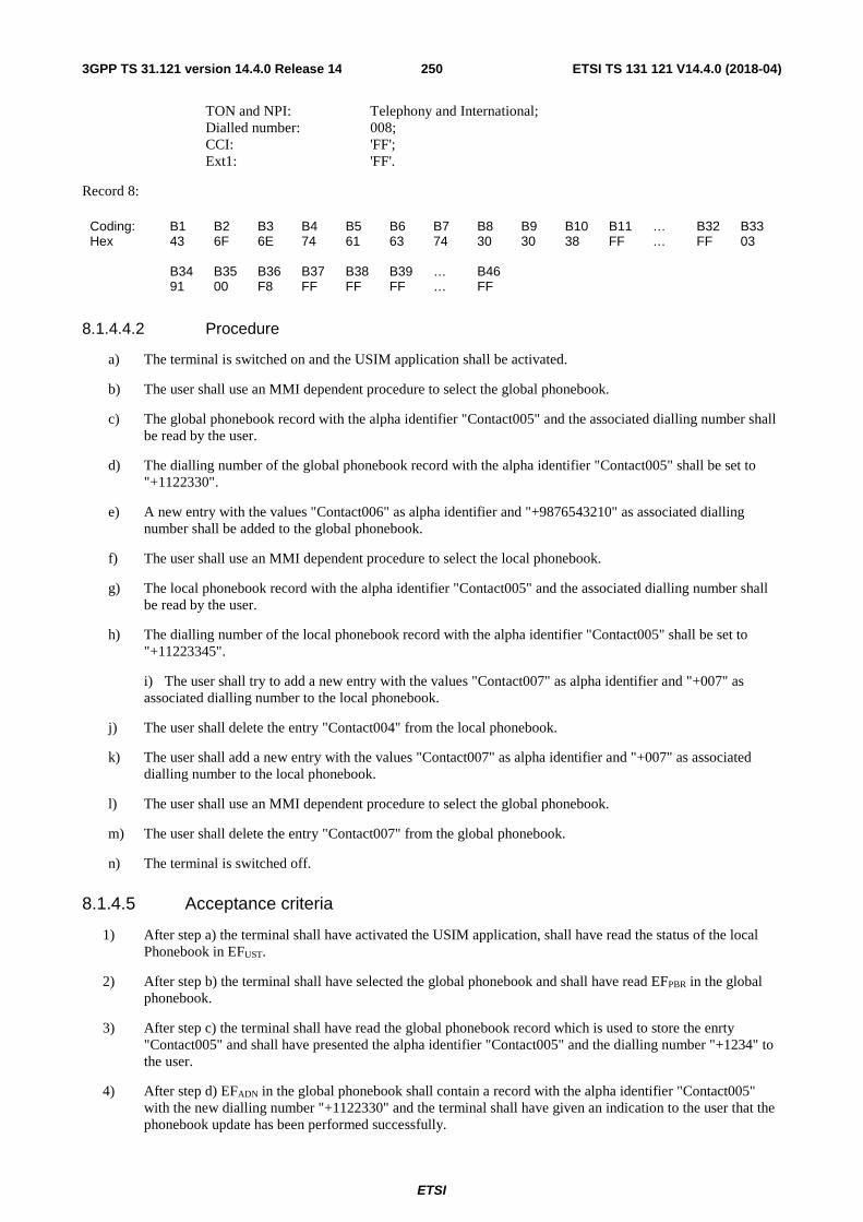
ETSI
ETSI TS 131 121 V14.4.0 (2018-04)2503GPP TS 31.121 version 14.4.0 Release 14
TON and NPI: Telephony and International; Dialled number: 008; CCI: 'FF'; Ext1: 'FF'.
Record 8:
Coding: B1 B2 B3 B4 B5 B6 B7 B8 B9 B10 B11 … B32 B33 Hex 43 6F 6E 74 61 63 74 30 30 38 FF … FF 03 B34 B35 B36 B37 B38 B39 … B46 91 00 F8 FF FF FF … FF
8.1.4.4.2 Procedure
a) The terminal is switched on and the USIM application shall be activated.
b) The user shall use an MMI dependent procedure to select the global phonebook.
c) The global phonebook record with the alpha identifier "Contact005" and the associated dialling number shall be read by the user.
d) The dialling number of the global phonebook record with the alpha identifier "Contact005" shall be set to "+1122330".
e) A new entry with the values "Contact006" as alpha identifier and "+9876543210" as associated dialling number shall be added to the global phonebook.
f) The user shall use an MMI dependent procedure to select the local phonebook.
g) The local phonebook record with the alpha identifier "Contact005" and the associated dialling number shall be read by the user.
h) The dialling number of the local phonebook record with the alpha identifier "Contact005" shall be set to "+11223345".
i) The user shall try to add a new entry with the values "Contact007" as alpha identifier and "+007" as associated dialling number to the local phonebook.
j) The user shall delete the entry "Contact004" from the local phonebook.
k) The user shall add a new entry with the values "Contact007" as alpha identifier and "+007" as associated dialling number to the local phonebook.
l) The user shall use an MMI dependent procedure to select the global phonebook.
m) The user shall delete the entry "Contact007" from the global phonebook.
n) The terminal is switched off.
8.1.4.5 Acceptance criteria
1) After step a) the terminal shall have activated the USIM application, shall have read the status of the local Phonebook in EFUST.
2) After step b) the terminal shall have selected the global phonebook and shall have read EFPBR in the global phonebook.
3) After step c) the terminal shall have read the global phonebook record which is used to store the enrty "Contact005" and shall have presented the alpha identifier "Contact005" and the dialling number "+1234" to the user.
4) After step d) EFADN in the global phonebook shall contain a record with the alpha identifier "Contact005" with the new dialling number "+1122330" and the terminal shall have given an indication to the user that the phonebook update has been performed successfully.
ETSI
ETSI TS 131 121 V14.4.0 (2018-04)2513GPP TS 31.121 version 14.4.0 Release 14
5) After step e) a new record shall have been added to EFADN in the global phonebook with the alpha identifier "Contact006" and the dialling number string "+9876543210".
6) After step f) the terminal shall have selected the local phonebook and shall have read EFPBR in the local phonebook.
7) After step g) the terminal shall have read the local phonebook record which is used to store the entry "Contact005" and shall have presented the alpha identifier "Contact005" and the dialling number "+1234" to the user.
8) After step h) EFADN in the local phonebook shall contain a record with the alpha identifier "Conatct005" and with new dialling number "+11223345" and the terminal shall have given an indication to the user that the phonebook update has been performed successfully.
9) After step i) the terminal shall have given an indication that update of the local phonebook can't be performed. EFADN shall have not been updated.
10) After step j) the local phonebook record which was used to store the entry "Contact004" shall be empty and the terminal shall have indicated that the deletion of the phonebook entry was performed successfully.
11) After step k) a new record shall have been added to EFADN in the local phonebook with the alpha identifier "Contact007" and the dialling number string "+007"
12) After step l) the terminal shall have selected the global phonebook and shall have read EFPBR in the global phonebook.
13) After step m) the global phonebook record which was used to store the entry "Contact007" shall be empty and the terminal shall have indicated that the deletion of the phonebook entry was performed successfully.
8.1.5 Local Phonebook handling
8.1.5.1 Definition and applicability
The UICC may contain a global phonebook, or application specific phonebooks, or both in parallel.
8.1.5.2 Conformance requirement
The terminal shall support the local phonebook as defined in TS 31.102 [4], subclause 4.4.2.
Reference:
- TS 31.102 [4], subclause 4.4.2.
8.1.5.3 Test purpose
1) To verify that the terminal supports the local phonebook without existence of the global phonebook.
2) To verify that the data contained in the local phonebook can be read and updated correctly.
8.1.5.4 Method of test
8.1.5.4.1 Initial conditions
The terminal is connected to the USIM Simulator.
The default USIM is used with the following exceptions:
The local phonebook is present, the global phonebook is not present.
The local phonebook shall contain:
EFPBR (Phonebook reference file)

ETSI
ETSI TS 131 121 V14.4.0 (2018-04)2523GPP TS 31.121 version 14.4.0 Release 14
Logically: Only EFADN and EFEXT1 are present in the local phonebook.
EFADN (Abbreviated dialling numbers)
Logically: 10 records, each record non-empty and unique. Record 4: Length of alpha identifier: 32 characters; Alpha identifier: "Contact004"; Length of BCD number: "03"; TON and NPI: Telephony and International; Dialled number: 004; CCI: 'FF'; Ext1: 'FF'.
Record 4:
Coding: B1 B2 B3 B4 B5 B6 B7 B8 B9 B10 B11 … B32 B33 Hex 43 6F 6E 74 61 63 74 30 30 34 FF … FF 03 B34 B35 B36 B37 B38 B39 … B46 91 00 F4 FF FF FF … FF
Record 5: Length of alpha identifier: 32 characters; Alpha identifier: "Contact005"; Length of BCD number: "03"; TON and NPI: Telephony and International; Dialled number: 1234; CCI: 'FF'; Ext1: 'FF'.
Record 5:
Coding: B1 B2 B3 B4 B5 B6 B7 B8 B9 B10 B11 … B32 B33 Hex 43 6F 6E 74 61 63 74 30 30 35 FF … FF 03 B34 B35 B36 B37 B38 B39 … B46 91 21 43 FF FF FF … FF
8.1.5.4.2 Procedure
a) The terminal is switched on and the USIM application shall be activated.
b) The user shall use an MMI dependent procedure to select the phonebook on the USIM (local phonebook).
c) The local phonebook record with the alpha identifier "Contact005" and the associated dialling number shall be read by the user.
d) The dialling number of the local phonebook record with the alpha identifier "Contact005" shall be set to "+11223345" and the alpha identifier shall be changed to "Contact8901234567890123456789012".
e) The user shall try to add a new entry with the values "Contact007" as alpha identifier and "+007" as associated dialling number to the local phonebook.
f) The user shall delete the entry "Contact004" from the local phonebook.
g) The user shall add a new entry with the values "Contact007" as alpha identifier and "+007" as associated dialling number to the local phonebook.
h) The terminal is switched off.

ETSI
ETSI TS 131 121 V14.4.0 (2018-04)2533GPP TS 31.121 version 14.4.0 Release 14
8.1.5.5 Acceptance criteria
1) After step a) the terminal shall have activated the USIM application, shall have read the status of the local Phonebook in EFUST.
2) After step b) the terminal shall have selected the local phonebook and shall have read EFPBR in the local phonebook.
3) After step c) the terminal shall have read the local phonebook record which is used to store the entry "Contact005" and shall have presented the alpha identifier "Contact005" and the dialling number "+1234" to the user.
4) After step d) EFADN in the local phonebook shall contain a record with the new alpha identifier "Contact8901234567890123456789012" and the dialling number "+11223345" and the terminal shall have given an indication to the user that the phonebook update has been performed successfully.
5) After step e) the terminal shall have given an indication that update of the local phonebook can't be performed. EFADN shall have not been updated.
6) After step f) the local phonebook record which was used to store the entry "Contact004" in the local phonebook shall be empty and the terminal shall have indicated that the deletion of the phonebook entry was performed successfully.
7) After step g) a new record shall have been added to EFADN in the local phonebook with the alpha identifier "Contact007" and the dialling number string "+007"
8.2 Short message handling report
8.2.1 Correct storage of a SM on the USIM
8.2.1.1 Definition and applicability
Once a SMS is received by the UE, the Terminal shall store the SM on the USIM, if this is indicated by the class 2 of the SMS (USIM specific SM). For this it is assumed, that at least one relevant SMS field are available on the USIM and they are indicated as empty.
8.2.1.2 Conformance requirement
The received class 2 SMS shall be stored on the USIM in EFSMS. The status of a received SMS, which has not been read yet, shall be set to "3" (SMS to be read).
- TS 23.038 [3], clause 4.
- TS 23.040 [13], subclause 10.1, operation 6;
- TS 24.011, subclauses 8.2.2, 8.2.3 and 8.2.5.4, Table 8.4 (part 2)
- TS 31.102 [4], subclauses 4.2.25.
8.2.1.3 Test purpose
1) To verify that the Terminal stored correctly the class 2 SMS on the USIM.
2) To verify that the Terminal sets the status of a received, and not yet read SMS to "3" (SMS to be read)
8.2.1.4 Method of test
8.2.1.4.1 Initial conditions
The default UICC is used with the following exceptions:

ETSI
ETSI TS 131 121 V14.4.0 (2018-04)2543GPP TS 31.121 version 14.4.0 Release 14
1) EFUST (USIM Service Table)
Logically: Local Phone Book available User controlled PLMN selector available Fixed dialling numbers available Barred dialling numbers available The GSM Access available The Group Identifier level 1 and level 2 not available SMS available SMS Status available Service n 33 (Packed Switched Domain) shall be set to '1'
Enabled Services Table available
Byte: B1 B2 B3 B4 B5 Binary xx1x xx11 xxxx X11x xxxx 1x00 xxxx x1xx xxxx xx11
The coding of EFUST shall conform with the capabilities of the USIM used.
2) EFSMS (Short Message Service) and EFSMSS (SMS Status) as defined in 8.2.4.4.1.
The USS (in case of a Terminal accessing UTRAN)/SS (in case of a Terminal accessing a GERAN) transmits on the BCCH, with the following network parameters:
- Attach/detach: disabled.
- LAI (MCC/MNC/LAC): 246/081/0001.
- Access control: unrestricted.
The USS/SS transmits the class 2 short message with the parameters as defined in 8.2.4.4.1.
User Equipment:
The UE is connected to the USIM-Simulator and the USS/SS.
8.2.1.4.2 Procedure
CS related sequence for UTRAN/GERAN
Perform the "CS related procedure" and continue with "Generic Procedure 1" as defined clause 8.2.4.4.2 as test "8.2.1" with the following parameters:
• Applicable Network Simulator (NWS): USS (UMTS System Simulator or System Simulator)
• CS is used to send and receive short messages
• ME supports UTRAN or GERAN
CS related procedure:
a) The ME is switched on and will perform the Profile Download, USIM initialization and network registration.
b) Continue with step c) of the Generic Procedure 1 as defined in 8.2.4.4.2.
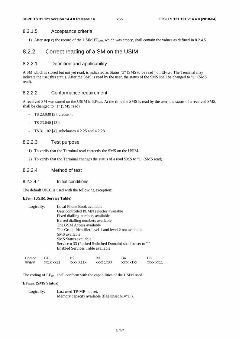
ETSI
ETSI TS 131 121 V14.4.0 (2018-04)2553GPP TS 31.121 version 14.4.0 Release 14
8.2.1.5 Acceptance criteria
1) After step c) the record of the USIM EFSMS which was empty, shall contain the values as defined in 8.2.4.5
8.2.2 Correct reading of a SM on the USIM
8.2.2.1 Definition and applicability
A SM which is stored but not yet read, is indicated as Status "3" (SMS to be read ) on EFSMS. The Terminal may indicate the user this status. After the SMS is read by the user, the status of the SMS shall be changed to "1" (SMS read).
8.2.2.2 Conformance requirement
A received SM was stored on the USIM in EFSMS. At the time the SMS is read by the user, the status of a received SMS, shall be changed to "1" (SMS read).
- TS 23.038 [3], clause 4.
- TS 23.040 [13];
- TS 31.102 [4], subclauses 4.2.25 and 4.2.28.
8.2.2.3 Test purpose
1) To verify that the Terminal read correctly the SMS on the USIM.
2) To verify that the Terminal changes the status of a read SMS to "1" (SMS read).
8.2.2.4 Method of test
8.2.2.4.1 Initial conditions
The default UICC is used with the following exception:
EFUST (USIM Service Table)
Logically: Local Phone Book available User controlled PLMN selector available Fixed dialling numbers available Barred dialling numbers available The GSM Access available The Group Identifier level 1 and level 2 not available SMS available SMS Status available Service n 33 (Packed Switched Domain) shall be set to '1'
Enabled Services Table available
Coding: B1 B2 B3 B4 B5 binary xx1x xx11 xxxx X11x xxxx 1x00 xxxx x1xx xxxx xx11
The coding of EFUST shall conform with the capabilities of the USIM used.
EFSMSS (SMS Status)
Logically: Last used TP-MR not set. Memory capacity available (flag unset b1="1").

ETSI
ETSI TS 131 121 V14.4.0 (2018-04)2563GPP TS 31.121 version 14.4.0 Release 14
Coding: B1 B2 Hex FF FF
EFSMS (Short Message Service)
Logically: Status byte set to SMS to be read. A chosen test is written in the text body of the EFSMS.
Record 1:
Coding: B1 B2 B3 B4 B5 B6 B7 B8 B9 B10 B11 B12 … B176 Hex 03 xx xx xx xx xx xx xx xx xx xx xx … xx
NOTE: "xx" shall be the appropriate text using the SMS default 7-bit coded alphabet as defined in TS 23.038 [3] which represents the stored SMS.
At least 9 records. Logically: Status byte set to empty no text is written (Remainder Bytes set to "FF").
Record:
Coding: B1 B2 B3 B4 B5 B6 B7 B8 B9 B10 B11 B12 … B176 Hex 00 FF FF FF FF FF FF FF FF FF FF FF … FF
A USS (in case of a Terminal accessing UTRAN) or a SS (in case of a Terminal accessing GERAN) is only needed to bring the UE into a defined idle mode. The USS/SS transmits on the BCCH:
- Attach/detach: disabled.
- LAI (MCC/MNC/LAC): 246/081/0001.
- Access control: unrestricted.
User Equipment:
The UE is in MM-state "idle, updated".
8.2.2.4.2 Procedure
a) After the UE has brought in idle state, the SMS shall be read.
b) The UE is powered off.
8.2.2.5 Acceptance criteria
1) After a) the correct text of the SMS shall be read from the UE display.
2) After step b) the EFSMS record 1 shall contains the following values:
Logically: Status byte set to SMS read. The entire content of the SMS shall be unchanged.
Record 1:
Coding: B1 B2 B3 B4 B5 B6 B7 B8 B9 B10 B11 B12 … B176 Hex 01 xx xx Xx xx xx xx xx xx xx xx xx … xx
NOTE: "xx" shall be the appropriate text using the SMS default 7-bit coded alphabet as defined in TS 23.038 [3] which represents the stored SMS.

ETSI
ETSI TS 131 121 V14.4.0 (2018-04)2573GPP TS 31.121 version 14.4.0 Release 14
8.2.3 SM memory capacity exceeded handling
8.2.3.1 Definition and applicability
Once a SMS is received by the UE, the Terminal shall store the SM on the USIM, if this is indicated by the class 2 of the SMS (USIM specific SM). For this it is assumed, that at least one relevant SMS field are available on the USIM and they are indicated as empty. If all SMS data field are full and furthermore all memory capacity reserved for SMS inside the ME is filled up to maximum and a SM was rejected, then this shall be indicated in the SMS Status file.
8.2.3.2 Conformance requirement
The received class 2 SMS shall be stored on the USIM in EFSMS. The status of a received SMS, which has not been read yet, shall be set to "3" (SMS to be read). If the terminal notifies the network that the terminal has been unable to accept a short message because its memory capacity has been exceeded, then the ME shall set the Memory Capacity Exceeded Notification Flag in the EFSMSS.
- TS 23.038 [3], clause 4.
- TS 23.040 [13], subclause 10.1, operation 6;
- TS 24.011, subclauses 8.2.2, 8.2.3 and 8.2.5.4, Table 8.4 (part 2)
- TS 31.102 [4], subclauses 4.2.25 and 4.2.28.
8.2.3.3 Test purpose
1) To verify that the Terminal stored correctly the class 2 SMS on the USIM.
2) To verify that the Terminal sets the status of a received, and not yet read SMS to "3" (SMS to be read).
3) To verify that the Terminal sets the memory full flag in EFSMSS if the terminal notifies the network that the terminal has been unable to accept a short message because its memory capacity has been exceeded.
8.2.3.4 Method of test
8.2.3.4.1 Initial conditions
The default UICC is used with the following exception:
EFUST (USIM Service Table)
Logically: Local Phone Book available User controlled PLMN selector available Fixed dialling numbers available Barred dialling numbers available The GSM Access available The Group Identifier level 1 and level 2 not available SMS available SMS Status available Service n 33 (Packed Switched Domain) shall be set to '1'
Enabled Services Table available
Coding: B1 B2 B3 B4 B5 binary xx1x xx11 xxxx X11x xxxx 1x00 xxxx x1xx xxxx xx11
The coding of EFUST shall conform with the capabilities of the USIM used.
EFSMS (Short Message Service)
At least 10 records. Record 1 shall be empty.

ETSI
ETSI TS 131 121 V14.4.0 (2018-04)2583GPP TS 31.121 version 14.4.0 Release 14
Logically: Status byte set to empty.
Record 1:
Coding: B1 B2 B3 B4 B5 B6 B7 B8 B9 B10 B11 B12 … B176 Hex 00 FF FF FF FF FF FF FF FF FF FF FF … FF
All other Record shall be full. Logically: Status byte set to SMS read. The text body of the record shall be filled with any appropriate text.
Records:
Coding: B1 B2 B3 B4 B5 B6 B7 B8 B9 B10 B11 B12 … B176 Hex 01 xx xx xx xx xx xx xx xx xx xx xx … xx
NOTE: "xx" shall be the appropriate text using the SMS default 7-bit coded alphabet as defined in TS 23.038 [3] which represents the received SMS.
EFSMSS (SMS Status)
Logically: Last used TP-MR not defined. Memory capacity available (flag unset b1="1").
Coding: B1 B2 Hex FF FF
The USS (in case of a Terminal accessing UTRAN) /SS (in case of a Terminal accessing a GERAN) transmits on the BCCH, with the following network parameters:
- Attach/detach: disabled.
- LAI (MCC/MNC/LAC): 246/081/0001.
- Access control: unrestricted.
The USS/ SS transmits the short messages with the following parameters:
Logically:
Class 2 SM:TS-Service Centre Address:
Bit 8: 1
Type-Of-Number: International number
Numbering-Plan-Identification: ISDN/telephony numbering plan
Address value: 112233445566
SMS TPDU:
TP-Message-Type-Indicator: SMS-DELIVER (in the direction SC to MS)
TP-More-Messages-to-Send: No more messages are waiting for the MS in this SC
TP-Reply-Path: TP-Reply-Path parameter is not set in this SMS-DELIVER
TP-User-Data-Header-Indicator: The TP-UD field contains only the short message
TP-Status-Report-Indication: A status report shall be returned to the SME
Bits 4-3: 00

ETSI
ETSI TS 131 121 V14.4.0 (2018-04)2593GPP TS 31.121 version 14.4.0 Release 14
TP-Originating-Address:
Bit 8: 1
Type-Of-Number: International number
Numbering-Plan-Identification: ISDN/telephony numbering plan
Address value: 012344556677
TP-Protocol-Identifier: No interworking, but SME-to-SME protocol
TP-Data-Coding-Scheme:
Bits 8-7: General Data Coding
Bit 6: Text is uncompressed
Bit 5: Bits 2-1 have a message class meaning
Bits 4-3: GSM 7 bit default alphabet
Bits 2-1: Class 2: (U)SIM specific message
TP-Service-Centre-Time-Stamp: 02-03-04 09:13:06 GMT + 1
TP-User-Data-Length: 160
TP-User-Data:
"Once a SMS is received by the UE, the Terminal shall store the SMS on the USIM, if this is indicated by the class 2 of the SMS (USIM specific SMS). For this…"
Class 1 SM:
The same content as for the Class 2 SMS except :
SMS TPDU:
TP-More-Messages-to-Send: More messages are waiting for the MS in this SC
TP-Data-Coding-Scheme:
Bits 2-1: Class 1: default meaning: ME-specific
TP-Service-Centre-Time-Stamp: Always set to current time of the system simulator
User Equipment:
The UE is in MM-state "idle, updated". If there is ME storage capacity available the storage for SMS inside the ME shall be able to allow for at least one more mobile terminated (e.g. Class 1) SM.
8.2.3.4.2 Procedure
a) After the UE is set to idle mode, the defined class 2 SM defined in 8.2.1.4.1 with 160 characters shall be sent to the UE.
b) After the UE has indicated that a SM was received, the SM shall not be read.
c) The USS starts sending Class 1 SMs as defined in 8.2.1.4.1 until the UE sends an RP-ERROR message with cause “Memory capacity exceeded”.
d) The UE is powered off.

ETSI
ETSI TS 131 121 V14.4.0 (2018-04)2603GPP TS 31.121 version 14.4.0 Release 14
8.2.3.5 Acceptance criteria
1) After step b) the record of the EFSMS which was empty, shall contain the following values:
Logically: Status byte set to SMS to be read The text of the received SMS shall be present in the record.
Record 1:
Logically:
Status:
RFU bits 8-6: 000
Status: Used space, message received by UE from network, message to be read
TS-Service Centre Address:
Bit 8: 1
Type-Of-Number: International number
Numbering-Plan-Identification: ISDN/telephony numbering plan
Address value: 112233445566
SMS TPDU:
TP-Message-Type-Indicator: SMS-DELIVER (in the direction SC to UE)
TP-More-Messages-to-Send: No more messages are waiting for the UE in this SC
TP-Reply-Path: TP-Reply-Path parameter is not set in this SMS-DELIVER
TP-User-Data-Header-Indicator: The TP-UD field contains only the short message
TP-Status-Report-Indication: A status report shall be returned to the SME
Bits 4-3: 00
TP-Originating-Address:
Bit 8: 1
Type-Of-Number: International number
Numbering-Plan-Identification: ISDN/telephony numbering plan
Address value: 012344556677
TP-Protocol-Identifier: No interworking, but SME-to-SME protocol
TP-Data-Coding-Scheme:
Bits 8-7: General Data Coding
Bit 6: Text is uncompressed
Bit 5: Bits 2-1 have a message class meaning
Bits 4-3: GSM 7 bit default alphabet
Bits 2-1: Class 2: (U)SIM specific message
TP-Service-Centre-Time-Stamp: 02-03-04 09:13:06 GMT + 1
TP-User-Data-Length: 160

ETSI
ETSI TS 131 121 V14.4.0 (2018-04)2613GPP TS 31.121 version 14.4.0 Release 14
TP-User-Data:
"Once a SMS is received by the UE, the Terminal shall store the SMS on the USIM, if this is indicated by the class 2 of the SMS (USIM specific SMS). For this …"
Coding: Hex 03 07 91 11 22 33 44 55 66 24 0C 91 10 32 44 55 66 77 00 12 20 30 40 90 31 60 40 A0 4F F7 B8 0C 0A 83 A6 CD 29 28 3D 07 C9 CB E3 72 DA 5E 26 83 C4 79 10 1D 5D 06 55 8B 2C 10 1D 5D 06 51 CB F2 76 DA 1D 66 83 E6 E8 30 9B 0D 9A D3 DF F2 32 88 8E 2E 83 A6 CD 29 E8 ED 06 D1 D1 65 50 75 9A 6C B2 40 69 33 88 8E 4E CF 41 E9 39 28 ED 26 A7 C7 61 7A 99 0C 12 E7 41 74 74 19 34 66 87 E7 73 90 0C F4 36 83 E8 E8 32 68 DA 9C 82 50 D5 69 B2 09 9A C3 CB E3 B4 39 3D 06 4D 9B D3 94 0B 64 7C CB 41 74 74 7A 0E 72 B9 5C
7) After step d) the Memory Capacity Exceeded Notification Flag in the EFSMSS shall be set to exceeded.
EFSMSS (SMS Status)
Logically: Last used TP-MR shall be set to any appropriate value. Memory capacity exceeded (flag set b1="0").
Coding: B1 B2 Hex xx FE
8.2.4 Correct storage of an SM on the UICC
8.2.4.1 Definition and applicability
For IMS: When a SIP MESSAGE request including a short message in the "vnd.3gpp.sms" payload is delivered and the extracted RP-DATA payload contains a Class 2 SM (USIM specific SM) the terminal shall store the SM on the USIM or ISIM. For this it is assumed, that at least one relevant SMS field are available on the USIM or ISIM and they are indicated as empty.
That the UE correctly implemented the role of an SMS-over-IP receiver is tested in clause 18.2 of TS 34.229-1 [33].
8.2.4.2 Conformance requirement
As TS 31.103[32] and TS 31.102[4] do not indicate in which of both applications a SM received via IMS shall be stored, the received Class 2 SM received via IMS shall be stored in EFSMS either on the USIM or on the ISIM. The status of a received SMS, which has not been read yet, shall be set to "3" (SMS to be read).
- TS 23.038 [3], clause 4.
- TS 23.040 [13], subclause 10.1, operation 6;
- TS 24.011, subclauses 7.3.1.1, 8.2.2, 8.2.3 and 8.2.5.4, Table 8.4 (part 2)
- TS 31.102 [4], subclauses 4.2.25,
- TS 31.103 [32], subclauses 4.2.12,
- TS 34.229 [33], Annexes C.2, C.18 and 18.2.

ETSI
ETSI TS 131 121 V14.4.0 (2018-04)2623GPP TS 31.121 version 14.4.0 Release 14
8.2.4.3 Test purpose
1) To verify that the Terminal stored correctly the class 2 SMS on the USIM or the ISIM.
2) To verify that the Terminal sets the status of a received, and not yet read SMS to "3" (SMS to be read).
8.2.4.4 Method of test
8.2.4.4.1 Initial conditions
The E-UTRAN/EPC ISIM-UICC is used with the following exception:
Logically: Local Phone Book available User controlled PLMN selector available Fixed dialling numbers available Barred dialling numbers available The GSM Access available The Group Identifier level 1 and level 2 not available SMS available SMS Status available Service n 33 (Packed Switched Domain) shall be set to '1'
Enabled Services Table available
Byte: B1 B2 B3 B4 B5 Binary xx1x xx11 xxxx X11x xxxx 1x00 xxxx x1xx xxxx xx11
The coding of EFUST shall conform with the capabilities of the USIM used.
EFSMS (Short Message Service) – For USIM and ISIM
At least 10 records. Record 1 shall be empty. Logically: Status byte set to empty.
Record 1:
Coding: B1 B2 B3 B4 B5 B6 B7 B8 B9 B10 B11 B12 … B176 Hex 00 FF FF FF FF FF FF FF FF FF FF FF … FF
All other Record shall be full. Logically: Status byte set to SMS read. The text body of the record shall be filled with any appropriate text.
Records:
Coding: B1 B2 B3 B4 B5 B6 B7 B8 B9 B10 B11 B12 … B176 Hex 01 xx xx xx xx xx xx xx xx xx xx xx … xx
NOTE: "xx" shall be the appropriate text using the SMS default 7-bit coded alphabet as defined in TS 23.038 [3] which represents the received SMS.
EFSMSS (SMS Status) – For USIM and ISIM
Logically: Last used TP-MR not defined. Memory capacity available (flag unset b1="1").
Coding: B1 B2 Hex FF FF

ETSI
ETSI TS 131 121 V14.4.0 (2018-04)2633GPP TS 31.121 version 14.4.0 Release 14
The NWS transmits on the BCCH, with the following network parameters:
- Attach/detach: disabled.
- USS LAI (MCC/MNC/LAC): 246/081/0001 (For UTRAN testing only)
- E-USS TAI (MCC/MNC/TAC): 246/081/0001 (For E-UTRAN testing only)
- Access control: unrestricted.
The NWS transmits the short messages with the following parameters:
Logically:
Class 2 SM: TS-Service Centre Address:
Bit 8: 1
Type-Of-Number: International number
Numbering-Plan-Identification: ISDN/telephony numbering plan
Address value: 112233445566
SMS TPDU:
TP-Message-Type-Indicator: SMS-DELIVER (in the direction SC to MS)
TP-More-Messages-to-Send: No more messages are waiting for the MS in this SC
TP-Reply-Path: TP-Reply-Path parameter is not set in this SMS-DELIVER
TP-User-Data-Header-Indicator: The TP-UD field contains only the short message
TP-Status-Report-Indication: A status report shall be returned to the SME
Bits 4-3: 00
TP-Originating-Address:
Bit 8: 1
Type-Of-Number: International number
Numbering-Plan-Identification: ISDN/telephony numbering plan
Address value: 012344556677
TP-Protocol-Identifier: No interworking, but SME-to-SME protocol
TP-Data-Coding-Scheme:
Bits 8-7: General Data Coding
Bit 6: Text is uncompressed
Bit 5: Bits 2-1 have a message class meaning
Bits 4-3: GSM 7 bit default alphabet
Bits 2-1: Class 2: (U)SIM specific message
TP-Service-Centre-Time-Stamp: 02-03-04 09:13:06 GMT + 1
TP-User-Data-Length: 160
TP-User-Data:

ETSI
ETSI TS 131 121 V14.4.0 (2018-04)2643GPP TS 31.121 version 14.4.0 Release 14
"Once a SMS is received by the UE, the Terminal shall store the SMS on the USIM, if this is indicated by the class 2 of the SMS (USIM specific SMS). For this…"
8.2.4.4.2 Procedure
Sequence A for IMS on UTRAN
a) The ME activates the required bearer, discovers the P-CSCF, and registers with the values from the ISIM with the IMS services (see Note 2).
b) Continue with step c) in the Generic Procedure 1.
Sequence B for IMS on E-UTRAN
a) The ME activates the required bearer, discovers the P-CSCF, and registers with the values from the ISIM with the IMS services (see Note 3).
b) Continue with step c) in the Generic Procedure 1.
Generic Procedure 1
c) After the UE is set to idle mode, the defined class 2 SM defined in 8.2.1.4.1 with 160 characters shall be sent to the UE (see Note 1) as specified in clause 18.2 of TS 34.229-1 [33] and use the SM payload defined in 8.2.1.4.1 in the Message-body of MESSAGE defined in clause A.7.1 in TS 34.229-1 [33].
d) After the UE has indicated that a SM was received, the SM shall not be read.
e) The UE is powered off.
Note 1: In case of IMS the Short Message is contained in the message body of the SIP MESSAGE. Note 2: For E-UTRAN: The EPS bearer context activation according to the procedures defined in TS 34.229-1 [33],
Annex C.2 and C.18 is performed. Note 3: For UTRAN: For SMS-over-IP a PDP context activation according to the procedures defined in TS 34.229-1
[33], Annex C.2 and C.17 is performed.
8.2.4.5 Acceptance criteria
1) After step d) the record of the EFSMS (on either the ISIM or USIM) which was empty, shall contain the following values:
Logically: Status byte set to SMS to be read The text of the received SMS shall be present in the record.
Record 1:
Logically:
Status:
RFU bits 8-6: 000
Status: Used space, message received by UE from network, message to be read
TS-Service Centre Address:
Bit 8: 1
Type-Of-Number: International number
Numbering-Plan-Identification: ISDN/telephony numbering plan
Address value: 112233445566

ETSI
ETSI TS 131 121 V14.4.0 (2018-04)2653GPP TS 31.121 version 14.4.0 Release 14
SMS TPDU:
TP-Message-Type-Indicator: SMS-DELIVER (in the direction SC to UE)
TP-More-Messages-to-Send: No more messages are waiting for the UE in this SC
TP-Reply-Path: TP-Reply-Path parameter is not set in this SMS-DELIVER
TP-User-Data-Header-Indicator: The TP-UD field contains only the short message
TP-Status-Report-Indication: A status report shall be returned to the SME
Bits 4-3: 00
TP-Originating-Address:
Bit 8: 1
Type-Of-Number: International number
Numbering-Plan-Identification: ISDN/telephony numbering plan
Address value: 012344556677
TP-Protocol-Identifier: No interworking, but SME-to-SME protocol
TP-Data-Coding-Scheme:
Bits 8-7: General Data Coding
Bit 6: Text is uncompressed
Bit 5: Bits 2-1 have a message class meaning
Bits 4-3: GSM 7 bit default alphabet
Bits 2-1: Class 2: (U)SIM specific message
TP-Service-Centre-Time-Stamp: 02-03-04 09:13:06 GMT + 1
TP-User-Data-Length: 160
TP-User-Data:
"Once a SMS is received by the UE, the Terminal shall store the SMS on the USIM, if this is indicated by the class 2 of the SMS (USIM specific SMS). For this …"
Coding: Hex 03 07 91 11 22 33 44 55 66 24 0C 91 10 32 44 55 66 77 00 12 20 30 40 90 31 60 40 A0 4F F7 B8 0C 0A 83 A6 CD 29 28 3D 07 C9 CB E3 72 DA 5E 26 83 C4 79 10 1D 5D 06 55 8B 2C 10 1D 5D 06 51 CB F2 76 DA 1D 66 83 E6 E8 30 9B 0D 9A D3 DF F2 32 88 8E 2E 83 A6 CD 29 E8 ED 06 D1 D1 65 50 75 9A 6C B2 40 69 33 88 8E 4E CF 41 E9 39 28 ED 26 A7 C7 61 7A 99 0C 12 E7 41 74 74 19 34 66 87 E7 73 90 0C F4 36 83 E8 E8 32 68 DA 9C 82 50 D5 69 B2 09 9A C3 CB E3 B4 39 3D 06 4D 9B D3 94 0B 64 7C CB 41 74 74 7A 0E 72 B9 5C

ETSI
ETSI TS 131 121 V14.4.0 (2018-04)2663GPP TS 31.121 version 14.4.0 Release 14
2) The UE shall pass the requirements which are verified in the MT SMS test case specified in clause 18.2 of TS 34.229-1 [33].
8.2.5 Correct reading of a SM on the USIM if USIM and ISIM are present
8.2.5.1 Definition and applicability
A SM which is stored but not yet read, is indicated as Status "3" (SMS to be read) on EFSMS. The Terminal may indicate the user this status. After the SMS is read by the user, the status of the SMS shall be changed to "1" (SMS read). This applies to short messages stored on the USIM and to short messages stored on the ISIM.
8.2.5.2 Conformance requirement
A received SM was stored in EFSMS on the ISIM and another SM was stored in EFSMS on the USIM. The user shall be able to read short messages stored on the USIM. At the time the SMS is read by the user, the status of a received SMS, shall be changed to "1" (SMS read).
- TS 23.038 [3], clause 4.
- TS 23.040 [13];
- TS 31.102 [4], subclauses 4.2.25 and 4.2.28,
- TS 31.103 [32], subclauses 4.2.12 and 4.2.13.
8.2.5.3 Test purpose
1) To verify that the Terminal correctly reads the SMS on the USIM if the USIM and ISIM are both present.
2) To verify that the Terminal changes the status of a read SMS to "1" (SMS read) of the message read from the USIM.
8.2.5.4 Method of test
8.2.5.4.1 Initial conditions
The E-UTRAN/EPC ISIM-UICC is used with the following exception:
EFUST (USIM Service Table)
As defined in in clause 4.5.2 with the expection that services n°10 (Short Message Storage) and n°11 (SMS Status Report) are available.
EFSMSS (SMS Status) on the USIM and on the ISIM
Logically: Last used TP-MR not set. Memory capacity available (flag unset b1="1").
Byte: B1 B2 Hex: FF FF
EFSMS (Short Message Service) on the USIM
Logically: Status byte set to SMS to be read. A chosen test is written in the text body of the EFSMS. This content shall be different from the
content stored in EFSMS in the ISIM.
Record 1:

ETSI
ETSI TS 131 121 V14.4.0 (2018-04)2673GPP TS 31.121 version 14.4.0 Release 14
Coding: B1 B2 B3 B4 B5 B6 B7 B8 B9 B10 B11 B12 … B176 Hex 03 xx xx xx Xx xx xx xx xx xx xx xx … xx NOTE: "xx" shall be the appropriate text using the SMS default 7-bit coded alphabet as defined in TS 23.038 [3]
which represents the stored SMS.
NOTE: "xx" shall be the appropriate text using the SMS default 7-bit coded alphabet as defined in TS 23.038 [3] which represents the stored SMS.
At least 9 records. Logically: Status byte set to empty no text is written (Remainder Bytes set to "FF").
Record:
Coding: B1 B2 B3 B4 B5 B6 B7 B8 B9 B10 B11 B12 … B176 Hex 00 FF FF FF FF FF FF FF FF FF FF FF … FF
EFSMS (Short Message Service) on the ISIM
Logically: Status byte set to SMS to be read. A chosen test is written in the text body of the EFSMS. This content shall be different from the
content stored in EFSMS in the USIM.
Record 1:
Byte: B1 B2 B3 B4 B5 B6 B7 B8 B9 B10 B11 B12 … B176 Hex: 03 yy yy yy Yy yy yy yy yy yy yy yy … yy NOTE: "yy" shall be the appropriate text using the SMS default 7-bit coded alphabet as defined in TS 23.038 [3]
which represents the stored SMS.
NOTE: "yy" shall be the appropriate text using the SMS default 7-bit coded alphabet as defined in TS 23.038 [3] which represents the stored SMS.
At least 9 records. Logically: Status byte set to empty no text is written (Remainder Bytes set to "FF").
Record:
Byte: B1 B2 B3 B4 B5 B6 B7 B8 B9 B10 B11 B12 … B176 Hex: 00 FF FF FF FF FF FF FF FF FF FF FF … FF
EFSMS on the USIM and EFSMS on the ISIM shall not share the same memory.
EFSMSS on the USIM and EFSMSS on the ISIM shall not share the same memory.
User Equipment:
The User Equipment is connected to the E-UTRAN/EPC ISIM-UICC.
8.2.5.4.2 Procedure
a) The UE is switched on.
b) The user shall read the SMS stored on the USIM.
c) The UE is switched off

ETSI
ETSI TS 131 121 V14.4.0 (2018-04)2683GPP TS 31.121 version 14.4.0 Release 14
8.2.5.5 Acceptance criteria
1) After b) the correct text of the SMS on the USIM shall be read and be displayed to the user.
2) After step b) the EFSMS record 1 of the USIM shall contains the following values:
Logically: Status byte set to SMS read. The entire content of the SMS shall be unchanged.
Record 1:
Byte: B1 B2 B3 B4 B5 B6 B7 B8 B9 B10 B11 B12 … B176 Hex: 01 xx xx xx Xx xx xx xx xx xx xx xx … xx NOTE: "xx" shall be the appropriate text using the SMS default 7-bit coded alphabet as defined in TS 23.038 [3]
which represents the stored SMS.
8.2.6 Correct reading of a SM on the ISIM if USIM and ISIM are present
8.2.6.1 Definition and applicability
A SM which is stored but not yet read, is indicated as Status "3" (SMS to be read) on EFSMS. The Terminal may indicate the user this status. After the SMS is read by the user, the status of the SMS shall be changed to "1" (SMS read). This applies to short messages stored on the USIM and to short messages stored on the ISIM.
8.2.6.2 Conformance requirement
A received SM was stored in EFSMS on the ISIM and another SM was stored in EFSMS on the USIM. The user shall be able to read short messages stored on the ISIM. At the time the SMS is read by the user, the status of a received SMS, shall be changed to "1" (SMS read).
- TS 23.038 [3], clause 4.
- TS 23.040 [13];
- TS 31.102 [4], subclauses 4.2.25 and 4.2.28,
- TS 31.103 [32], subclauses 4.2.12 and 4.2.13.
8.2.6.3 Test purpose
1) To verify that the Terminal correctly reads the SMS on the ISIM if the USIM and ISIM are both present.
2) To verify that the Terminal changes the status of a read SMS to "1" (SMS read) of the message read from the ISIM.
8.2.6.4 Method of test
8.2.6.4.1 Initial conditions
The E-UTRAN/EPC ISIM-UICC is used with the following exception:
EFUST (USIM Service Table)
As defined in in clause 4.5.2 with the expection that services n°10 (Short Message Storage) and n°11 (SMS Status Report) are available.
EFSMSS (SMS Status) on the USIM and on the ISIM
3) After step b) the EFSMS and EFSMSS on the ISIM shall remain unchanged.

ETSI
ETSI TS 131 121 V14.4.0 (2018-04)2693GPP TS 31.121 version 14.4.0 Release 14
Logically: Last used TP-MR not set. Memory capacity available (flag unset b1="1").
Byte: B1 B2 Hex: FF FF
EFSMS (Short Message Service) on the USIM
Logically: Status byte set to SMS to be read. A chosen test is written in the text body of the EFSMS. This content shall be different from the
content stored in EFSMS in the ISIM.
Record 1:
Coding: B1 B2 B3 B4 B5 B6 B7 B8 B9 B10 B11 B12 … B176 Hex 03 xx xx xx Xx xx xx xx xx xx xx xx … xx NOTE: "xx" shall be the appropriate text using the SMS default 7-bit coded alphabet as defined in TS 23.038 [3]
which represents the stored SMS.
NOTE: "xx" shall be the appropriate text using the SMS default 7-bit coded alphabet as defined in TS 23.038 [3] which represents the stored SMS.
At least 9 records. Logically: Status byte set to empty no text is written (Remainder Bytes set to "FF").
Record:
Coding: B1 B2 B3 B4 B5 B6 B7 B8 B9 B10 B11 B12 … B176 Hex 00 FF FF FF FF FF FF FF FF FF FF FF … FF
EFSMS (Short Message Service) on the ISIM
Logically: Status byte set to SMS to be read. A chosen test is written in the text body of the EFSMS. This content shall be different from the
content stored in EFSMS in the USIM.
Record 1:
Byte: B1 B2 B3 B4 B5 B6 B7 B8 B9 B10 B11 B12 … B176 Hex: 03 yy yy yy Yy yy yy yy yy yy yy yy … yy NOTE: "yy" shall be the appropriate text using the SMS default 7-bit coded alphabet as defined in TS 23.038 [3]
which represents the stored SMS.
NOTE: "yy" shall be the appropriate text using the SMS default 7-bit coded alphabet as defined in TS 23.038 [3] which represents the stored SMS.
At least 9 records. Logically: Status byte set to empty no text is written (Remainder Bytes set to "FF").
Record:
Byte: B1 B2 B3 B4 B5 B6 B7 B8 B9 B10 B11 B12 … B176 Hex: 00 FF FF FF FF FF FF FF FF FF FF FF … FF
EFSMS on the USIM and EFSMS on the ISIM shall not share the same memory.
EFSMSS on the USIM and EFSMSS on the ISIM shall not share the same memory.

ETSI
ETSI TS 131 121 V14.4.0 (2018-04)2703GPP TS 31.121 version 14.4.0 Release 14
User Equipment:
The User Equipment is connected to the E-UTRAN/EPC ISIM-UICC.
8.2.6.4.2 Procedure
a) The UE is switched on.
b) The user shall read the SMS stored on the USIM.
c) The UE is switched off
8.2.6.5 Acceptance criteria
1) After b) the correct text of the SMS on the ISIM shall be read and be displayed to the user.
2) After step b) the EFSMS record 1 of the ISIM shall contains the following values:
Logically: Status byte set to SMS read. The entire content of the SMS shall be unchanged.
Record 1:
Byte: B1 B2 B3 B4 B5 B6 B7 B8 B9 B10 B11 B12 … B176 Hex: 01 yy yy yy yy yy yy yy yy yy yy yy … Yy NOTE: "yy" shall be the appropriate text using the SMS default 7-bit coded alphabet as defined in TS 23.038 [3]
which represents the stored SMS.
3) After step b) the EFSMS and EFSMSS on the USIM shall remain unchanged.
8.2.7 Correct storage of an SM on the UICC
8.2.7.1 Definition and applicability
Once a SMS is received by the UE, the Terminal shall store the SM on the USIM, if this is indicated by the class 2 of the SMS (USIM specific SM). For this it is assumed, that at least one relevant SMS field is available on the USIM and indicated as empty
8.2.7.2 Conformance requirement
The received class 2 SMS shall be stored on the USIM in EFSMS. The status of a received SMS, which has not been read yet, shall be set to "3" (SMS to be read).
- TS 23.038 [3], clause 4.
- TS 23.040 [13], subclause 10.1, operation 6;
- TS 24.011, subclauses 7.3.1.1, 8.2.2, 8.2.3 and 8.2.5.4, Table 8.4 (part 2)
- TS 31.102 [4], subclauses 4.2.25.
- TS 24.301 [26], subclauses 5.6.3, 5.6.3.3.
8.2.7.3 Test purpose
1) To verify that the Terminal stored correctly the class 2 SMS on the USIM.
2) To verify that the Terminal sets the status of a received, and not yet read SMS to "3" (SMS to be read).

ETSI
ETSI TS 131 121 V14.4.0 (2018-04)2713GPP TS 31.121 version 14.4.0 Release 14
8.2.7.4 Method of test
8.2.7.4.1 Initial conditions
The default E-UTRAN UICC is used with the following exceptions
3) EFSMS (Short Message Service) and EFSMSS (SMS Status) as defined in 8.2.4.4.1.
The NB-SS transmits on the BCCH, with the following network parameters:
- Attach/detach: disabled.
- TAI (MCC/MNC/TAC): 246/081/0001
- Access control: unrestricted.
The NB-SS transmits the class 2 short message with the parameters as defined in 8.2.4.4.1.
8.2.7.4.2 Procedure
a) The ME is switched on and will perform USIM initialization and network registration.
b) SMS over SGs (DOWNLINK NAS TRANSPORT and UPLINK NAS TRANSPORT messages) is used to send and receive short messages.
c) Continue with step c) of the Generic Procedure 1 as defined in 8.2.4.4.2.
8.2.7.5 Acceptance criteria
1) After step c) the record of the USIM EFSMS which was empty, shall contain the values as defined in 8.2.4.5
8.3 MMS related tests
8.3.1 UE recognising the priority order of MMS Issuer Connectivity Parameters
8.3.1.1 Definition and applicability
An MMS User Agent shall use the MMS related information stored in the USIM, if present, unless otherwise specified by the user. Some of these sets of MMS connectivity parameters are preset by the issuer of the USIM with the first supported set being the default. This information is used to connect to the network for purpose of accessing the MMS Relay/Server.
The MMS connectivity information on the USIM includes preferences for the selection of Interface to Core Network and Bearer parameters. If these are stored on the USIM the MMS-capable UE shall automatically select the Interface to Core Network and Bearer parameters based on their order of precedence defined on the USIM unless otherwise specified by the user.
MMS user preferences information, which is stored on the USIM, shall be used by an MMS User Agent for user assistance in preparation of terminal-originated MMs (e.g. default values for parameters that are often used).
8.3.1.2 Conformance requirement
The Terminal's MMS User Agent shall use the MMS connectivity parameters stored first in the supported parameter sets of EFMMSICP as default parameters to connect to the network for MMS purposes (i.e. sending an User generated MM).
- TS 31.102 [4], subclauses 4.2.69 and 5.3.30;

ETSI
ETSI TS 131 121 V14.4.0 (2018-04)2723GPP TS 31.121 version 14.4.0 Release 14
- TS 23.140 [23], subclause 7.1.14 and Annex F.
MMS user preferences information, which is stored on the USIM, shall be used by an MMS User Agent for user assistance in preparation of terminal-originated MMs.
- TS 31.102 [4], subclauses 4.2.70 and 5.3.31;
- TS 23.140 [23], subclause 7.1.14 and Annex F.
8.3.1.3 Test purpose
1) To verify that the Terminal's MMS User Agent uses the MMS connectivity parameter stored on the USIM to connect to the network for MMS purposes.
2) To verify that the Terminal's MMS User Agent uses the first stored set of supported parameters in EFMMSICP as default.
3) To verify that the Terminal's MMS User Agent uses the MMS user preference information stored on the USIM for user assistance in preparation of terminal-originated MMs.
8.3.1.4 Method of test
8.3.1.4.1 Initial conditions
Four MMS Relays/Servers are available:
MMS Relay/Server 1:
7) MMS Connectivity Parameters MMS implementation information: "WAP"
MMS Relay/Server MMS Relay/Server information: "http://mms-operator1.com"
Interface to Core Network and Bearer Bearer: "GSM-CSD" Address: "+496998625" Type of address: "E164" Speed: "Autobauding" Call type: "ANALOG_MODEM" Authentication type: "PAP" Authentication id: "B2B_OTS1" Authentication pw: "B2B_password1"
Gateway Address: "170.187.51.3" Type of address: "Ipv4" Port : "9201" Service: "CO-WSP" Authentication type: "HTTP BASIC" Authentication id: "gateway_user1" Authentication pw: "gateway_password1"
MMS Relay/Server 2:

ETSI
ETSI TS 131 121 V14.4.0 (2018-04)2733GPP TS 31.121 version 14.4.0 Release 14
7) MMS Connectivity Parameters MMS implementation information: "WAP"
MMS Relay/Server MMS Relay/Server information: "http://mms-operator1.com"
Interface to Core Network and Bearer Bearer: "GSM-CSD" Address: "+496998626" Type of address: "E164" Speed: "Autobauding" Call type: "ANALOG_MODEM" Authentication type: "PAP" Authentication id: "B2C_OTS2" Authentication pw: "B2C_password2"
Gateway Address: "170.187.51.3" Type of address: "Ipv4" Port : "9201" Service: "CO-WSP" Authentication type: "HTTP BASIC" Authentication id: "gateway_user1" Authentication pw: "gateway_password1"
MMS Relay/Server 3:
7) MMS Connectivity Parameters MMS implementation information: "WAP"
MMS Relay/Server MMS Relay/Server information: "http://mms-operator1.com"
Interface to Core Network and Bearer Bearer: "GSM-GPRS" Address: "wap.B2B-operator1.com" Type of address: "APN" Call type: "ANALOG_MODEM" Delivery of erroneous SDU: "No" Residual Bit Error Rate: "1*10-5" SDU-Error-Ratio: "1*10-6" Traffic-class: "Interactive class" Maximum bit rate for downlink: "8 kbps" Authentication type: "PAP" Authentication id: "B2B_OTS1" Authentication pw: "B2B_password1"
Gateway Address: "170.187.51.3" Type of address: "Ipv4" Port : "9201" Service: "CO-WSP" Authentication type: "HTTP BASIC" Authentication id: "gateway_user1" Authentication pw: "gateway_password1"
MMS Relay/Server 4:

ETSI
ETSI TS 131 121 V14.4.0 (2018-04)2743GPP TS 31.121 version 14.4.0 Release 14
7) MMS Connectivity Parameters MMS implementation information: "WAP"
MMS Relay/Server MMS Relay/Server information: "http://mms-operator1.com"
Interface to Core Network and Bearer Bearer: "GSM-GPRS" Address: "wap.B2C-operator1.com" Type of address: "APN" Call type: "ANALOG_MODEM" Delivery of erroneous SDU: "No" Residual Bit Error Rate: "1*10-5" SDU-Error-Ratio: "1*10-6" Traffic-class: "Interactive class" Maximum bit rate for downlink: "8 kbps" Authentication type: "PAP" Authentication id: "B2C_OTS2" Authentication pw: "B2C_password2"
Gateway Address: "170.187.51.3" Type of address: "Ipv4" Port : "9201" Service: "CO-WSP" Authentication type: "HTTP BASIC" Authentication id: "gateway_user1" Authentication pw: "gateway_password1"
The default UICC is used with the following exceptions:
EFUST (USIM Service Table)
Logically: Local Phone Book available User controlled PLMN selector available Fixed dialling numbers available Barred dialling numbers available The GSM Access available The Group Identifier level 1 and level 2 not available SMS available SMS Status available Service no. 33 (Packed Switched Domain) shall be set to '1'
Service no. 52 Multimedia Messaging Service available Service no. 55 MMS User Connectivity Parameters not available
Coding: B1 B2 B3 B4 B5 B6 B7 Binary xx1x xx11 x11x xxxx xxxx 1x00 xxxx x1xx xxxx xxx1 xxxx xxxx x0xx 1xxx
EFMMSN
Logically: MMS Status: Free space MMS Implementation : "00" MMS Notification: "FF FF … FF" (251 bytes) Extension file record number: "FF"
Coding: B1 B2 B3 B4 B5 … B254 B255 00 00 00 FF FF FF FF
EFMMSICP

ETSI
ETSI TS 131 121 V14.4.0 (2018-04)2753GPP TS 31.121 version 14.4.0 Release 14
Logically: MMS Connectivity Parameters
MMS Implementation MMS Implementation Information : "WAP"
MMS Relay/Server MMS Relay/Server Address "http://mms-operator1.com"
1st Interface to Core Network and Bearer Bearer: "GSM-CSD" Address: "+496998625" Type of address: "E164" Speed: "Autobauding" Call type: "ANALOG_MODEM" Authentication type: "PAP" Authentication id: "B2B_OTS1" Authentication pw: "B2B_password1"
2nd Interface to Core Network and Bearer Bearer: "GSM-CSD" Address: "+496998626" Type of address: "E164" Speed: "Autobauding" Call type: "ANALOG_MODEM" Authentication type: "PAP" Authentication id: "B2C_OTS2" Authentication pw: "B2C_password2"
3rd Interface to Core Network and Bearer Bearer: "GSM-GPRS" Address: "wap.B2B-operator1.com" Type of address: "APN" Call type: "ANALOG_MODEM" Delivery of erroneous SDU: "No" Residual Bit Error Rate: "1*10-5" SDU-Error-Ratio: "1*10-6" Traffic-class: "Interactive class" Maximum bit rate for downlink: "8 kbps" Authentication type: "PAP" Authentication id: "B2B_OTS1" Authentication pw: "B2B_password1"
4th Interface to Core Network and Bearer Bearer: "GSM-GPRS" Address: "wap.B2C-operator1.com" Type of address: "APN" Call type: "ANALOG_MODEM" Delivery of erroneous SDU: "No" Residual Bit Error Rate: "1*10-5"

ETSI
ETSI TS 131 121 V14.4.0 (2018-04)2763GPP TS 31.121 version 14.4.0 Release 14
SDU-Error-Ratio: "1*10-6" Traffic-class: "Interactive class" Maximum bit rate for downlink: "8 kbps" Authentication type: "PAP" Authentication id: "B2C_OTS2" Authentication pw: "B2C_password2"
Gateway: Address: "170.187.51.3" Type of address: "Ipv4" Port : "9201" Service: "CO-WSP" Authentication type: "HTTP BASIC" Authentication id: "gateway_user1" Authentication pw: "gateway_password1"
Coding: AB 82 01 47 80 01 01 81 18 68 74 74 70 3A 2F 2F 6D 6D 73 2E 6F 70 65 72 61 74 6F 72 31 2E 63 6F 6D 82 2F 10 AA 08 2B 34 39 36 39 39 38 36 32 35 00 09 87 25 C5 0A 90 0C 9A 0D 42 32 42 11 4F 54 53 31 00 0E 42 32 42 11 70 61 73 73 77 6F 72 64 31 00 82 2F 10 AA 08 2B 34 39 36 39 39 38 36 32 36 00 09 87 25 C5 0A 90 0C 9A 0D 42 32 43 11 4F 54 53 32 00 0E 42 32 43 11 70 61 73 73 77 6F 72 64 32 00 82 43 10 AB 08 03 77 61 70 0D 42 32 42 2D 6F 70 65 72 61 74 6F 72 31 03 63 6F 6D 00 09 89 0A 90 31 03 37 70 38 06 33 60 36 08 0C 9A 0D 42 32 42 11 4F 54 53 31 00 0E 42 32 42 11 70 61 73 73 77 6F 72 64 31 00 82 43 10 AB 08 03 77 61 70 0D 42 32 43 2D 6F 70 65 72 61 74 6F 72 31 03 63 6F 6D 00 09 89 0A 90 31 03 37 70 38 06 33 60 36 08 0C 9A 0D 42 32 43 11 4F 54 53 32 00 0E 42 32 43 11 70 61 73 73 77 6F 72 64 32 00 83 43 20 31 37 30 2E 31 38 37 2E 35 31 2E 33 00 21 85 23 39 32 30 31 00 24 CB 19 9C 1A 67 61 74 65 77 61 79 11 75 73 65 72 31 00 1B 67 61 74 65 77 61 79 11 70 61 73 73 77 6F 72 64 31 00
EFMMSUP
Logically:
MMS Implementation MMS implementation information: "WAP"
MMS User Preference Profile Name: "Greeting cards" MMS User Information Preference Information
Visibility: "hide" Delivery report: "yes" Read-reply: "yes" Priority: "normal" Delivery-Time:
Value (absolute): "1-Jan-2003, 12:00:00 AM GMT" Expiry:
Value (relative): 1104537600 seconds
Coding: 80 01 01 81 0E 47 72 65 65 74 69 6E 67 20 63 61 72 64 73 82 19 14 80 06 80 10 80 0F 81 07 07 80 05 00 3E 12 2F 80 08 06 81 04 41 D5 E8 00

ETSI
ETSI TS 131 121 V14.4.0 (2018-04)2773GPP TS 31.121 version 14.4.0 Release 14
The UICC is installed into the Terminal and the user has indicated the data stored in EFMMSICP as default.
8.3.1.4.2 Procedure
a) The Terminal is powered on and the PIN shall be entered.
b) When the Terminal is in idle mode the user shall generate an MM using the MMS User Agent on the Terminal with the default MMS connectivity settings provided by the card issuer and the MMS user preference information stored in the card and send it to "+0123456789".
8.3.1.5 Acceptance criteria
1) After step b) the Terminal shall have read the set of supported MMS connectivity parameters stored first in EFMMSICP.
2) After step b) the Terminal shall have sent the MM to "+0123456789" using the MMS connectivity parameters stored first in the supported parameter sets in EFMMSICP.
3) After step b) the Terminal shall have sent the MM to "+0123456789" using the MMS user preference information stored in EFMMSUP.
8.3.2 UE recognising the priority order of MMS User Connectivity Parameters
8.3.2.1 Definition and applicability
An MMS User Agent shall use the MMS related information stored in the USIM, if present, unless otherwise specified by the user. The MMS connectivity parameters determined by the user, with the first supported set being the default, shall be used to connect to the network for purpose of accessing the MMS Relay/Server.
The MMS connectivity information on the USIM includes preferences for the selection of Interface to Core Network and Bearer parameters. If these are stored on the USIM the MMS-capable UE shall automatically select the Interface to Core Network and Bearer parameters based on their order of precedence defined on the USIM unless otherwise specified by the user.
MMS user preferences information, which is stored on the USIM, shall be used by an MMS User Agent for user assistance in preparation of terminal-originated MMs (e.g. default values for parameters that are often used).
8.3.2.2 Conformance requirement
When using the MMS User Connectivity Parameters to connect to the network for MMS purposes (i.e. sending an User generated MM), the Terminal's MMS User Agent shall use the MMS User Connectivity Parameters with the highest priority (as defined by its position in EFMMSUCP) unless otherwise specified by the user.
- TS 31.102 [4], subclauses 4.2.71 and 5.3.32;
- TS 23.140 [23], subclause 7.1.14 and Annex F.
MMS user preferences information, which is stored on the USIM, shall be used by an MMS User Agent for user assistance in preparation of terminal-originated MMs.
- TS 31.102 [4], subclauses 4.2.70 and 5.3.31;
- TS 23.140 [23], subclause 7.1.14 and Annex F.
8.3.2.3 Test purpose
1) To verify that the Terminal's MMS User Agent uses the MMS connectivity parameter stored on the USIM to connect to the network for MMS purposes.

ETSI
ETSI TS 131 121 V14.4.0 (2018-04)2783GPP TS 31.121 version 14.4.0 Release 14
2) To verify that when using the MMS User Connectivity Parameters to connect to the network for MMS purposes the Terminal's MMS User Agent uses the set of supported parameters in EF MMSUCP with the highest priority (as defined by its position in EFMMSUCP).
3) To verify that the Terminal's MMS User Agent uses the MMS user preference information stored on the USIM for user assistance in preparation of terminal-originated MMs.
8.3.2.4 Method of test
8.3.2.4.1 Initial conditions
Four MMS Relays/Servers are available:
MMS Relay/Server 1:
7) MMS Connectivity Parameters MMS implementation information: "WAP"
MMS Relay/Server MMS Relay/Server information: "http://mms-operator2.com"
Interface to Core Network and Bearer Bearer: "GSM-CSD" Address: "+495251699" Type of address: "E164" Speed: "Autobauding" Call type: "ANALOG_MODEM" Authentication type: "PAP" Authentication id: "UDO_OTS1" Authentication pw: "Udo_password1"
Gateway Address: "170.187.51.4" Type of address: "Ipv4" Port : "9203" Service: "CO-WSP" Authentication type: "HTTP BASIC" Authentication id: "gateway_user7" Authentication pw: "gateway_password7"
MMS Relay/Server 2:
7) MMS Connectivity Parameters MMS implementation information: "WAP"
MMS Relay/Server MMS Relay/Server information: "http://mms-operator2.com"
Interface to Core Network and Bearer Bearer: "GSM-CSD" Address: "+495251700" Type of address: "E164" Speed: "Autobauding" Call type: "ANALOG_MODEM" Authentication type: "PAP" Authentication id: "UDO_OTS2" Authentication pw: "Udo_password2"
Gateway Address: "170.187.51.4" Type of address: "Ipv4" Port : "9203" Service: "CO-WSP" Authentication type: "HTTP BASIC" Authentication id: "gateway_user7" Authentication pw: "gateway_password7"
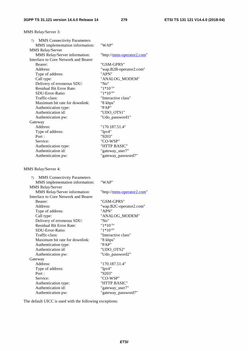
ETSI
ETSI TS 131 121 V14.4.0 (2018-04)2793GPP TS 31.121 version 14.4.0 Release 14
MMS Relay/Server 3:
7) MMS Connectivity Parameters MMS implementation information: "WAP"
MMS Relay/Server MMS Relay/Server information: "http://mms-operator2.com"
Interface to Core Network and Bearer Bearer: "GSM-GPRS" Address: "wap.B2B-operator2.com" Type of address: "APN" Call type: "ANALOG_MODEM" Delivery of erroneous SDU: "No" Residual Bit Error Rate: "1*10-5" SDU-Error-Ratio: "1*10-6" Traffic-class: "Interactive class" Maximum bit rate for downlink: "8 kbps" Authentication type: "PAP" Authentication id: "UDO_OTS1" Authentication pw: "Udo_password1"
Gateway Address: "170.187.51.4" Type of address: "Ipv4" Port : "9203" Service: "CO-WSP" Authentication type: "HTTP BASIC" Authentication id: "gateway_user7" Authentication pw: "gateway_password7"
MMS Relay/Server 4:
7) MMS Connectivity Parameters MMS implementation information: "WAP"
MMS Relay/Server MMS Relay/Server information: "http://mms-operator2.com"
Interface to Core Network and Bearer Bearer: "GSM-GPRS" Address: "wap.B2C-operator2.com" Type of address: "APN" Call type: "ANALOG_MODEM" Delivery of erroneous SDU: "No" Residual Bit Error Rate: "1*10-5" SDU-Error-Ratio: "1*10-6" Traffic-class: "Interactive class" Maximum bit rate for downlink: "8 kbps" Authentication type: "PAP" Authentication id: "UDO_OTS2" Authentication pw: "Udo_password2"
Gateway Address: "170.187.51.4" Type of address: "Ipv4" Port : "9203" Service: "CO-WSP" Authentication type: "HTTP BASIC" Authentication id: "gateway_user7" Authentication pw: "gateway_password7"
The default UICC is used with the following exceptions:

ETSI
ETSI TS 131 121 V14.4.0 (2018-04)2803GPP TS 31.121 version 14.4.0 Release 14
EFUST (USIM Service Table)
Logically: Local Phone Book available User controlled PLMN selector available Fixed dialling numbers available Barred dialling numbers available The GSM Access available The Group Identifier level 1 and level 2 not available SMS available SMS Status available Service no. 33 (Packed Switched Domain) shall be set to '1'
Service no. 52 Multimedia Messaging Service available Service no. 55 MMS User Connectivity Parameters available
Coding: B1 B2 B3 B4 B5 B6 B7 Binary xx1x xx11 x11x xxxx xxxx 1x00 xxxx x1xx xxxx xxx1 xxxx xxxx x1xx 1xxx
EFMMSN
Logically: MMS Status: Free space MMS Implementation : "00" MMS Notification: "FF FF … FF" (251 bytes) Extension file record number: "FF"
Coding: B1 B2 B3 B4 B5 … B254 B255 00 00 00 FF FF FF FF
EFMMSICP
Logically: Empty
Coding: B1 B2 … Bxx FF FF FF
EFMMSUP
Logically:
MMS Implementation MMS implementation information: "WAP"
MMS User Preference Profile Name: "Greeting cards" MMS User Information Preference Information
Visibility: "hide" Delivery report: "yes" Read-reply: "yes" Priority: "normal" Delivery-Time:
Value (absolute): "1-Jan-2003, 12:00:00 AM GMT" Expiry:
Value (relative): 1104537600 seconds
Coding: 80 01 01 81 0E 47 72 65 65 74 69 6E 67 20 63 61 72 64 73 82 19 14 80 06 80 10 80 0F 81 07 07 80 05 00 3E 12 2F 80 08 06 81 04 41 D5 E8 00
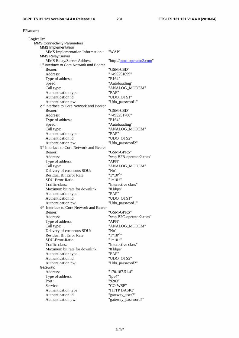
ETSI
ETSI TS 131 121 V14.4.0 (2018-04)2813GPP TS 31.121 version 14.4.0 Release 14
EFMMSUCP
Logically: MMS Connectivity Parameters
MMS Implementation MMS Implementation Information : "WAP"
MMS Relay/Server MMS Relay/Server Address "http://mms-operator2.com"
1st Interface to Core Network and Bearer Bearer: "GSM-CSD" Address: "+495251699" Type of address: "E164" Speed: "Autobauding" Call type: "ANALOG_MODEM" Authentication type: "PAP" Authentication id: "UDO_OTS1" Authentication pw: "Udo_password1"
2nd Interface to Core Network and Bearer Bearer: "GSM-CSD" Address: "+495251700" Type of address: "E164" Speed: "Autobauding" Call type: "ANALOG_MODEM" Authentication type: "PAP" Authentication id: "UDO_OTS2" Authentication pw: "Udo_password2"
3rd Interface to Core Network and Bearer Bearer: "GSM-GPRS" Address: "wap.B2B-operator2.com" Type of address: "APN" Call type: "ANALOG_MODEM" Delivery of erroneous SDU: "No" Residual Bit Error Rate: "1*10-5" SDU-Error-Ratio: "1*10-6" Traffic-class: "Interactive class" Maximum bit rate for downlink: "8 kbps" Authentication type: "PAP" Authentication id: "UDO_OTS1" Authentication pw: "Udo_password1"
4th Interface to Core Network and Bearer Bearer: "GSM-GPRS" Address: "wap.B2C-operator2.com" Type of address: "APN" Call type: "ANALOG_MODEM" Delivery of erroneous SDU: "No" Residual Bit Error Rate: "1*10-5" SDU-Error-Ratio: "1*10-6" Traffic-class: "Interactive class" Maximum bit rate for downlink: "8 kbps" Authentication type: "PAP" Authentication id: "UDO_OTS2" Authentication pw: "Udo_password2"
Gateway: Address: "170.187.51.4" Type of address: "Ipv4" Port : "9203" Service: "CO-WSP" Authentication type: "HTTP BASIC" Authentication id: "gateway_user7" Authentication pw: "gateway_password7"

ETSI
ETSI TS 131 121 V14.4.0 (2018-04)2823GPP TS 31.121 version 14.4.0 Release 14
Coding: AB 82 01 47 80 01 01 81 18 68 74 74 70 3A 2F 2F 6D 6D 73 2E 6F 70 65 72 61 74 6F 72 32 2E 63 6F 6D 82 2F 10 AA 08 2B 34 39 35 32 35 31 36 39 39 00 09 87 25 C5 0A 90 0C 9A 0D 55 44 4F 11 4F 54 53 31 00 0E 55 64 6F 11 70 61 73 73 77 6F 72 64 31 00 82 2F 10 AA 08 2B 34 39 35 32 35 31 37 30 30 00 09 87 25 C5 0A 90 0C 9A 0D 55 44 4F 11 4F 54 53 32 00 0E 55 64 6F 11 70 61 73 73 77 6F 72 64 32 00 82 43 10 AB 08 03 77 61 70 0D 42 32 42 2D 6F 70 65 72 61 74 6F 72 32 03 63 6F 6D 00 09 89 0A 90 31 03 37 70 38 06 33 60 36 08 0C 9A 0D 55 44 4F 11 4F 54 53 31 00 0E 55 64 6F 11 70 61 73 73 77 6F 72 64 31 00 82 43 10 AB 08 03 77 61 70 0D 42 32 43 2D 6F 70 65 72 61 74 6F 72 32 03 63 6F 6D 00 09 89 0A 90 31 03 37 70 38 06 33 60 36 08 0C 9A 0D 55 44 4F 11 4F 54 53 32 00 0E 55 64 6F 11 70 61 73 73 77 6F 72 64 32 00 83 3B 20 31 37 30 2E 31 38 37 2E 35 31 2E 34 00 21 85 23 39 32 30 31 00 24 CB 19 9C 1A 67 61 74 65 77 61 79 11 75 73 65 72 37 00 1B 67 61 74 65 77 61 79 11 70 61 73 73 77 6F 72 64 37 00
The UICC is installed into the Terminal and the user has indicated the data stored in EFMMSUCPas default.
8.3.2.4.2 Procedure
a) The Terminal is powered on and the PIN shall be entered.
b) When the Terminal is in idle mode the user shall generate an MM using the MMS User Agent on the Terminal with the default MMS User Connectivity Parameters and the MMS user preference information stored in the card and send it to "+0123456789".
8.3.2.5 Acceptance criteria
1) After step b) the Terminal shall have read the first supported set of MMS connectivity parameters stored in EFMMSUCP.
2) After step b) the Terminal shall have sent the MM to "+0123456789" using the MMS User Connectivity Parameter set with the highest priority (as defined by its position in EFMMSUCP), which can be used to access an available MMS Relay/Server.
3) After step b) the Terminal shall have sent the MM to "+0123456789" using the MMS user preference information stored in EFMMSUCP.
8.3.3 UE recognising the priority order of MMS Issuer Connectivity Parameters over the MMS User Connectivity Parameters
8.3.3.1 Definition and applicability
An MMS User Agent shall use the MMS related information stored in the USIM, if present, unless otherwise specified by the user. This information comprises MMS connectivity information, MMS user preferences and MMS notifications.
MMS user preferences information, which is stored on the USIM, shall be used by an MMS User Agent for user assistance in preparation of terminal-originated MMs (e.g. default values for parameters that are often used).
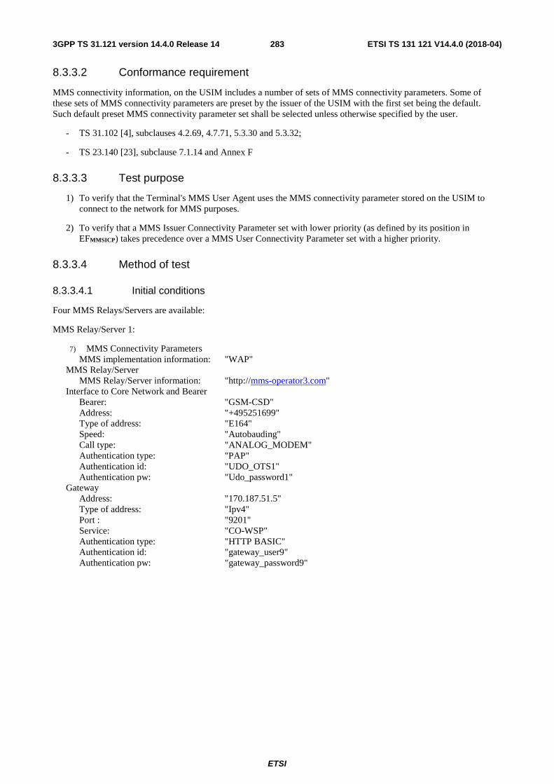
ETSI
ETSI TS 131 121 V14.4.0 (2018-04)2833GPP TS 31.121 version 14.4.0 Release 14
8.3.3.2 Conformance requirement
MMS connectivity information, on the USIM includes a number of sets of MMS connectivity parameters. Some of these sets of MMS connectivity parameters are preset by the issuer of the USIM with the first set being the default. Such default preset MMS connectivity parameter set shall be selected unless otherwise specified by the user.
- TS 31.102 [4], subclauses 4.2.69, 4.7.71, 5.3.30 and 5.3.32;
- TS 23.140 [23], subclause 7.1.14 and Annex F
8.3.3.3 Test purpose
1) To verify that the Terminal's MMS User Agent uses the MMS connectivity parameter stored on the USIM to connect to the network for MMS purposes.
2) To verify that a MMS Issuer Connectivity Parameter set with lower priority (as defined by its position in EFMMSICP) takes precedence over a MMS User Connectivity Parameter set with a higher priority.
8.3.3.4 Method of test
8.3.3.4.1 Initial conditions
Four MMS Relays/Servers are available:
MMS Relay/Server 1:
7) MMS Connectivity Parameters MMS implementation information: "WAP"
MMS Relay/Server MMS Relay/Server information: "http://mms-operator3.com"
Interface to Core Network and Bearer Bearer: "GSM-CSD" Address: "+495251699" Type of address: "E164" Speed: "Autobauding" Call type: "ANALOG_MODEM" Authentication type: "PAP" Authentication id: "UDO_OTS1" Authentication pw: "Udo_password1"
Gateway Address: "170.187.51.5" Type of address: "Ipv4" Port : "9201" Service: "CO-WSP" Authentication type: "HTTP BASIC" Authentication id: "gateway_user9" Authentication pw: "gateway_password9"

ETSI
ETSI TS 131 121 V14.4.0 (2018-04)2843GPP TS 31.121 version 14.4.0 Release 14
MMS Relay/Server 2:
7) MMS Connectivity Parameters MMS implementation information: "WAP"
MMS Relay/Server MMS Relay/Server information: "http://mms-operator3.com"
Interface to Core Network and Bearer Bearer: "GSM-GPRS" Address: "wap.B2P-operator3.com" Type of address: "APN" Call type: "ANALOG_MODEM" Delivery of erroneous SDU: "No" Residual Bit Error Rate: "1*10-5" SDU-Error-Ratio: "1*10-6" Traffic-class: "Interactive class" Maximum bit rate for downlink: "8 kbps" Authentication type: "PAP" Authentication id: "UDO_OTS1" Authentication pw: "Udo_password1"
Gateway Address: "170.187.51.5" Type of address: "Ipv4" Port : "9201" Service: "CO-WSP" Authentication type: "HTTP BASIC" Authentication id: "gateway_user9" Authentication pw: "gateway_password9"
MMS Relay/Server 3:
7) MMS Connectivity Parameters MMS implementation information: "WAP"
MMS Relay/Server MMS Relay/Server information: "http://mms-operator3.com"
Interface to Core Network and Bearer Bearer: "GSM-CSD" Address: "+496998626" Type of address: "E164" Speed: "Autobauding" Call type: "ANALOG_MODEM" Authentication type: "PAP" Authentication id: "B2C_OTS2" Authentication pw: "B2C_password2"
Gateway Address: "170.187.51.5" Type of address: "Ipv4" Port : "9201" Service: "CO-WSP" Authentication type: "HTTP BASIC" Authentication id: "gateway_user9" Authentication pw: "gateway_password9"

ETSI
ETSI TS 131 121 V14.4.0 (2018-04)2853GPP TS 31.121 version 14.4.0 Release 14
MMS Relay/Server 4:
7) MMS Connectivity Parameters MMS implementation information: "WAP"
MMS Relay/Server MMS Relay/Server information: "http://mms-operator3.com"
Interface to Core Network and Bearer Bearer: "GSM-GPRS" Address: "wap.B2C-operator3.com" Type of address: "APN" Call type: "ANALOG_MODEM" Delivery of erroneous SDU: "No" Residual Bit Error Rate: "1*10-5" SDU-Error-Ratio: "1*10-6" Traffic-class: "Interactive class" Maximum bit rate for downlink: "8 kbps" Authentication type: "PAP" Authentication id: "B2C_OTS2" Authentication pw: "B2C_password2"
Gateway Address: "170.187.51.5" Type of address: "Ipv4" Port : "9201" Service: "CO-WSP" Authentication type: "HTTP BASIC" Authentication id: "gateway_user9" Authentication pw: "gateway_password9"
The default UICC is used with the following exceptions:
EFUST (USIM Service Table)
Logically: Local Phone Book available User controlled PLMN selector available Fixed dialling numbers available Barred dialling numbers available The GSM Access available The Group Identifier level 1 and level 2 not available SMS available SMS Status available Service no. 33 (Packed Switched Domain) shall be set to '1'
Service no. 52 Multimedia Messaging Service available Service no. 55 MMS User Connectivity Parameters available
Coding: B1 B2 B3 B4 B5 B6 B7 Binary xx1x xx11 x11x xxxx xxxx 1x00 xxxx x1xx xxxx xxx1 xxxx xxxx x1xx 1xxx
EFMMSN
Logically: MMS Status: Free space MMS Implementation : "00" MMS Notification: "FF FF … FF" (251 bytes) Extension file record number: "FF"
Coding: B1 B2 B3 B4 B5 … B254 B255 00 00 00 FF FF FF FF
EFMMSICP

ETSI
ETSI TS 131 121 V14.4.0 (2018-04)2863GPP TS 31.121 version 14.4.0 Release 14
Logically: MMS Connectivity Parameters
MMS Implementation MMS Implementation Information : "WAP"
MMS Relay/Server MMS Relay/Server Address "http://mms-operator3.com"
1st Interface to Core Network and Bearer Bearer: "GSM-CSD" Address: "+496998625" Type of address: "E164" Speed: "Autobauding" Call type: "ANALOG_MODEM" Authentication type: "PAP" Authentication id: "B2B_OTS1" Authentication pw: "B2B_password1"
2nd Interface to Core Network and Bearer Bearer: "GSM-CSD" Address: "+496998626" Type of address: "E164" Speed: "Autobauding" Call type: "ANALOG_MODEM" Authentication type: "PAP" Authentication id: "B2C_OTS2" Authentication pw: "B2C_password2"
3rd Interface to Core Network and Bearer Bearer: "GSM-GPRS" Address: "wap.B2B-operator3.com" Type of address: "APN" Call type: "ANALOG_MODEM" Delivery of erroneous SDU: "No" Residual Bit Error Rate: "1*10-5" SDU-Error-Ratio: "1*10-6" Traffic-class: "Interactive class" Maximum bit rate for downlink: "8 kbps" Authentication type: "PAP" Authentication id: "B2B_OTS1" Authentication pw: "B2B_password1"
4th Interface to Core Network and Bearer Bearer: "GSM-GPRS" Address: "wap.B2C-operator3.com" Type of address: "APN" Call type: "ANALOG_MODEM" Delivery of erroneous SDU: "No" Residual Bit Error Rate: "1*10-5" SDU-Error-Ratio: "1*10-6" Traffic-class: "Interactive class" Maximum bit rate for downlink: "8 kbps" Authentication type: "PAP" Authentication id: "B2C_OTS2" Authentication pw: "B2C_password2"
Gateway: Address: "170.187.51.5" Type of address: "Ipv4" Port : "9201" Service: "CO-WSP" Authentication type: "HTTP BASIC" Authentication id: "gateway_user9" Authentication pw: "gateway_password9"

ETSI
ETSI TS 131 121 V14.4.0 (2018-04)2873GPP TS 31.121 version 14.4.0 Release 14
Coding: AB 82 01 47 80 01 01 81 18 68 74 74 70 3A 2F 2F 6D 6D 73 2E 6F 70 65 72 61 74 6F 72 33 2E 63 6F 6D 82 2F 10 AA 08 2B 34 39 36 39 39 38 36 32 35 00 09 87 25 C5 0A 90 0C 9A 0D 42 32 42 11 4F 54 53 31 00 0E 42 32 42 11 70 61 73 73 77 6F 72 64 31 00 82 2F 10 AA 08 2B 34 39 36 39 39 38 36 32 36 00 09 87 25 C5 0A 90 0C 9A 0D 42 32 43 11 4F 54 53 32 00 0E 42 32 43 11 70 61 73 73 77 6F 72 64 32 00 82 43 10 AB 08 03 77 61 70 0D 42 32 42 2D 6F 70 65 72 61 74 6F 72 33 03 63 6F 6D 00 09 89 0A 90 31 03 37 70 38 06 33 60 36 08 0C 9A 0D 42 32 42 11 4F 54 53 31 00 0E 42 32 42 11 70 61 73 73 77 6F 72 64 31 00 82 43 10 AB 08 03 77 61 70 0D 42 32 43 2D 6F 70 65 72 61 74 6F 72 33 03 63 6F 6D 00 09 89 0A 90 31 03 37 70 38 06 33 60 36 08 0C 9A 0D 42 32 43 11 4F 54 53 32 00 0E 42 32 43 11 70 61 73 73 77 6F 72 64 32 00 83 3B 20 31 37 30 2E 31 38 37 2E 35 31 2E 35 00 21 85 23 39 32 30 31 00 24 CB 19 9C 1A 67 61 74 65 77 61 79 11 75 73 65 72 39 00 1B 67 61 74 65 77 61 79 11 70 61 73 73 77 6F 72 64 39 00
EFMMSUP
Logically:
MMS Implementation MMS implementation information: "WAP"
MMS User Preference Profile Name: "Greeting cards" MMS User Information Preference Information
Visibility: "hide" Delivery report: "yes" Read-reply: "yes" Priority: "normal" Delivery-Time:
Value (absolute): "1-Jan-2003, 12:00:00 AM GMT" Expiry:
Value (relative): 1104537600 seconds
Coding: 80 01 01 81 0E 47 72 65 65 74 69 6E 67 20 63 61 72 64 73 82 19 14 80 06 80 10 80 0F 81 07 07 80 05 00 3E 12 2F 80 08 06 81 04 41 D5 E8 00

ETSI
ETSI TS 131 121 V14.4.0 (2018-04)2883GPP TS 31.121 version 14.4.0 Release 14
EFMMSUCP
Logically: MMS Connectivity Parameters
MMS Implementation MMS Implementation Information : "WAP"
MMS Relay/Server MMS Relay/Server Address "http://mms-operator3.com"
1st Interface to Core Network and Bearer Bearer: "GSM-CSD" Address: "+495251699" Type of address: "E164" Speed: "Autobauding" Call type: "ANALOG_MODEM" Authentication type: "PAP" Authentication id: "UDO_OTS1" Authentication pw: "Udo_password1"
2nd Interface to Core Network and Bearer Bearer: "GSM-CSD" Address: "+495251700" Type of address: "E164" Speed: "Autobauding" Call type: "ANALOG_MODEM" Authentication type: "PAP" Authentication id: "UDO_OTS2" Authentication pw: "Udo_password2"
3rd Interface to Core Network and Bearer Bearer: "GSM-GPRS" Address: "wap.B2P-operator3.com" Type of address: "APN" Call type: "ANALOG_MODEM" Delivery of erroneous SDU: "No" Residual Bit Error Rate: "1*10-5" SDU-Error-Ratio: "1*10-6" Traffic-class: "Interactive class" Maximum bit rate for downlink: "8 kbps" Authentication type: "PAP" Authentication id: "UDO_OTS1" Authentication pw: "Udo_password1"
4th Interface to Core Network and Bearer Bearer: "GSM-GPRS" Address: "wap.B2C-operator3.com" Type of address: "APN" Call type: "ANALOG_MODEM" Delivery of erroneous SDU: "No" Residual Bit Error Rate: "1*10-5" SDU-Error-Ratio: "1*10-6" Traffic-class: "Interactive class" Maximum bit rate for downlink: "8 kbps" Authentication type: "PAP" Authentication id: "UDO_OTS2" Authentication pw: "Udo_password2"
Gateway: Address: "170.187.51.5" Type of address: "Ipv4" Port : "9201" Service: "CO-WSP" Authentication type: "HTTP BASIC" Authentication id: "gateway_user9" Authentication pw: "gateway_password9"

ETSI
ETSI TS 131 121 V14.4.0 (2018-04)2893GPP TS 31.121 version 14.4.0 Release 14
Coding: AB 82 01 47 80 01 01 81 18 68 74 74 70 3A 2F 2F 6D 6D 73 2D 6F 70 65 72 61 74 6F 72 33 2E 63 6F 6D 82 2F 10 AA 08 2B 34 39 35 32 35 31 36 39 39 00 09 87 25 C5 0A 90 0C 9A 0D 55 44 4F 11 4F 54 53 31 00 0E 55 64 6F 11 70 61 73 73 77 6F 72 64 31 00 82 2F 10 AA 08 2B 34 39 35 32 35 31 37 30 30 00 09 87 25 C5 0A 90 0C 9A 0D 55 44 4F 11 4F 54 53 32 00 0E 55 64 6F 11 70 61 73 73 77 6F 72 64 32 00 82 43 10 AB 08 03 77 61 70 0D 42 32 50 2D 6F 70 65 72 61 74 6F 72 33 03 63 6F 6D 00 09 89 0A 90 31 03 37 70 38 06 33 60 36 08 0C 9A 0D 55 44 4F 11 4F 54 53 31 00 0E 55 64 6F 11 70 61 73 73 77 6F 72 64 31 00 82 43 10 AB 08 03 77 61 70 0D 42 32 43 2D 6F 70 65 72 61 74 6F 72 33 03 63 6F 6D 00 09 89 0A 90 31 03 37 70 38 06 33 60 36 08 0C 9A 0D 55 44 4F 11 4F 54 53 32 00 0E 55 64 6F 11 70 61 73 73 77 6F 72 64 32 00 83 3C 20 31 37 30 2E 31 38 37 2E 35 31 2E 35 00 21 85 23 39 32 30 31 00 24 CB 19 9C 1A 67 61 74 65 77 61 79 11 75 73 65 72 39 00 1B 67 61 74 65 77 61 79 11 70 61 73 73 77 6F 72 64 39 00
The UICC is installed into the Terminal and the user hasn't specified a default MMS connectivity parameter set.
8.3.3.4.2 Procedure
a) The Terminal is powered on and the PIN shall be entered.
b) When the Terminal is in idle mode the user shall generate an MM using the MMS User Agent on the Terminal with the default MMS connectivity parameter set and send it to "+0123456789". If no MMS Relay/Server is available for this parameter set, the next MMS connectivity parameter set offered by the MMS User Agent shall be used to send the MM.
8.3.3.5 Acceptance criteria
After step b) the Terminal shall have sent the MM to "+0123456789" using the first supported MMS connectivity parameter set, which can be used to access an available MMS Relay/Server and is stored in EFMMSICP.
8.3.4 Usage of MMS notification
8.3.4.1 Definition and applicability
An MMS User Agent shall use the MMS related information stored in the USIM, if present, unless otherwise specified by the user. This information comprises MMS connectivity information, MMS user preferences and MMS notifications. MMS notifications should be stored on the USIM together with an associated status by a MMS User Agent according to TS 23.140 [23].
8.3.4.2 Conformance requirement
A Terminal supporting MMS notification storage on the USIM shall store MMS notifications together with an associated status on the USIM.
- TS 31.102 [4], subclauses 4.2.67 and 5.3.29;
- TS 23.140 [23], subclauses 7.1.12, 7.1.14, 8.1.4 and Annex F.

ETSI
ETSI TS 131 121 V14.4.0 (2018-04)2903GPP TS 31.121 version 14.4.0 Release 14
8.3.4.3 Test purpose
To verify that the Terminal stores and updates MMS notifications with the associated status on the USIM correctly.
8.3.4.4 Method of test
8.3.4.4.1 Initial conditions
Two MMS Relays/Servers are available:
MMS Relay/Server 1:
MMS Connectivity Parameters MMS implementation information: "WAP"
MMS Relay/Server MMS Relay/Server information: "http://mms-operator1.com"
Interface to Core Network and Bearer Bearer: "GSM-CSD" Address: "+496998625" Type of address: "E164" Speed: "Autobauding" Call type: "ANALOG_MODEM" Authentication type: "PAP" Authentication id: "B2B_OTS1" Authentication pw: "B2B_password1"
Gateway Address: "170.187.51.3" Type of address: "Ipv4" Port: "9201" Service: "CO-WSP" Authentication type: "HTTP BASIC" Authentication id: "gateway_user1" Authentication pw: "gateway_password1"

ETSI
ETSI TS 131 121 V14.4.0 (2018-04)2913GPP TS 31.121 version 14.4.0 Release 14
MMS Relay/Server 2:
7) MMS Connectivity Parameters MMS implementation information: "WAP"
MMS Relay/Server MMS Relay/Server information: "http://mms-operator1.com"
Interface to Core Network and Bearer Bearer: "GSM-GPRS" Address: "wap.B2B-operator1.com" Type of address: "APN" Call type: "ANALOG_MODEM" Delivery of erroneous SDU: "No" Residual Bit Error Rate: "1*10-5" SDU-Error-Ratio: "1*10-6" Traffic-class: "Interactive class" Maximum bit rate for downlink: "8 kbps" Authentication type: "PAP" Authentication id: "B2B_OTS1" Authentication pw: "B2B_password1"
Gateway Address: "170.187.51.3" Type of address: "Ipv4" Port: "9201" Service: "CO-WSP" Authentication type: "HTTP BASIC" Authentication id: "gateway_user1" Authentication pw: "gateway_password1"
The default UICC is used with the following exceptions:
EFUST (USIM Service Table)
Logically: Local Phone Book available User controlled PLMN selector available Fixed dialling numbers available Barred dialling numbers available The GSM Access available The Group Identifier level 1 and level 2 not available SMS available SMS Status available Service no. 33 (Packed Switched Domain) shall be set to '1'
Service no. 52 Multimedia Messaging Service available Service no. 53 Extension 8 available Service no. 55 MMS User Connectivity Parameters not available
Coding: B1 B2 B3 B4 B5 B6 B7 Binary xx1x xx11 x11x xxxx xxxx 1x00 xxxx x1xx xxxx xxx1 xxxx xxxx x0x1 1xxx
EFMMSN
Logically: MMS Status: Free space MMS Implementation : "00" MMS Notification: "FF FF … FF" (251 bytes) Extension file record number: "FF"
Coding: B1 B2 B3 B4 B5 … B254 B255 00 00 00 FF FF FF FF
EFMMSUP
Logically:

ETSI
ETSI TS 131 121 V14.4.0 (2018-04)2923GPP TS 31.121 version 14.4.0 Release 14
MMS Implementation MMS implementation information: "WAP"
MMS User Preference Profile Name: "Greeting cards" MMS User Information Preference Information
Visibility: "hide" Delivery report: "yes" Read-reply: "yes" Priority: "normal" Delivery-Time:
Value (absolute): "1-Jan-2003, 12:00:00 AM GMT" Expiry:
Value (relative): 1104537600 seconds
Coding: 80 01 01 81 0E 47 72 65 65 74 69 6E 67 20 63 61 72 64 73 82 19 14 80 06 80 10 80 0F 81 07 07 80 05 00 3E 12 2F 80 08 06 81 04 41 D5 E8 00
EFMMSICP
Logically: MMS Connectivity Parameters
MMS Implementation MMS Implementation Information : "WAP"
MMS Relay/Server MMS Relay/Server Address "http://mms-operator1.com"
1st Interface to Core Network and Bearer Bearer: "GSM-CSD" Address: "+496998625" Type of address: "E164" Speed: "Autobauding" Call type: "ANALOG_MODEM" Authentication type: "PAP" Authentication id: "B2B_OTS1" Authentication pw: "B2B_password1"
2nd Interface to Core Network and Bearer Bearer: "GSM-CSD" Address: "+496998626" Type of address: "E164" Speed: "Autobauding" Call type: "ANALOG_MODEM" Authentication type: "PAP" Authentication id: "B2C_OTS2" Authentication pw: "B2C_password2"
3rd Interface to Core Network and Bearer Bearer: "GSM-GPRS" Address: "wap.B2B-operator1.com" Type of address: "APN" Call type: "ANALOG_MODEM" Delivery of erroneous SDU: "No" Residual Bit Error Rate: "1*10-5"

ETSI
ETSI TS 131 121 V14.4.0 (2018-04)2933GPP TS 31.121 version 14.4.0 Release 14
SDU-Error-Ratio: "1*10-6" Traffic-class: "Interactive class" Maximum bit rate for downlink: "8 kbps" Authentication type: "PAP" Authentication id: "B2B_OTS1" Authentication pw: "B2B_password1"
4th Interface to Core Network and Bearer Bearer: "GSM-GPRS" Address: "wap.B2C-operator1.com" Type of address: "APN" Call type: "ANALOG_MODEM" Delivery of erroneous SDU: "No" Residual Bit Error Rate: "1*10-5" SDU-Error-Ratio: "1*10-6" Traffic-class: "Interactive class" Maximum bit rate for downlink: "8 kbps" Authentication type: "PAP" Authentication id: "B2C_OTS2" Authentication pw: "B2C_password2"
Gateway: Address: "170.187.51.3" Type of address: "Ipv4" Port: "9201" Service: "CO-WSP" Authentication type: "HTTP BASIC" Authentication id: "gateway_user1" Authentication pw: "gateway_password1"
Coding: AB 82 01 47 80 01 01 81 18 68 74 74 70 3A 2F 2F 6D 6D 73 2E 6F 70 65 72 61 74 6F 72 31 2E 63 6F 6D 82 2F 10 AA 08 2B 34 39 36 39 39 38 36 32 35 00 09 87 25 C5 0A 90 0C 9A 0D 42 32 42 11 4F 54 53 31 00 0E 42 32 42 11 70 61 73 73 77 6F 72 64 31 00 82 2F 10 AA 08 2B 34 39 36 39 39 38 36 32 36 00 09 87 25 C5 0A 90 0C 9A 0D 42 32 43 11 4F 54 53 32 00 0E 42 32 43 11 70 61 73 73 77 6F 72 64 32 00 82 43 10 AB 08 03 77 61 70 0D 42 32 42 2D 6F 70 65 72 61 74 6F 72 31 03 63 6F 6D 00 09 89 0A 90 31 03 37 70 38 06 33 60 36 08 0C 9A 0D 42 32 42 11 4F 54 53 31 00 0E 42 32 42 11 70 61 73 73 77 6F 72 64 31 00 82 43 10 AB 08 03 77 61 70 0D 42 32 43 2D 6F 70 65 72 61 74 6F 72 31 03 63 6F 6D 00 09 89 0A 90 31 03 37 70 38 06 33 60 36 08 0C 9A 0D 42 32 43 11 4F 54 53 32 00 0E 42 32 43 11 70 61 73 73 77 6F 72 64 32 00 83 3C 20 31 37 30 2E 31 38 37 2E 35 31 2E 33 00 21 85 23 39 32 30 31 00 24 CB 19 9C 1A 67 61 74 65 77 61 79 11 75 73 65 72 31 00 1B 67 61 74 65 77 61 79 11 70 61 73 73 77 6F 72 64 31 00
EFEXT8
Logically: At least 10 records.
Record 1 to 10: Free space with 253 bytes for extension data
Record 1:

ETSI
ETSI TS 131 121 V14.4.0 (2018-04)2943GPP TS 31.121 version 14.4.0 Release 14
Coding: B1 B2 B3 B4 … … B255 Hex 00 FF FF FF FF
The UICC is installed into the Terminal and the user hasn't specified a default MMS connectivity parameter set.
8.3.4.4.2 Procedure
a) The terminal is powered on and the PIN shall be entered.
b) When the terminal is in idle mode a MM shall be sent to the terminal via the MMS Relay/Server 1 or 2, dependent on the bearer supported by the terminal. This MMS Relay/Server shall then generate a notification to the Terminal's MMS User Agent. With the MM notification the MMS User Agent shall receive a message reference that can be used for retrieving the MM from this MMS Relay/Server.
The MM shall result in a MMS notification with the following predefined values:
X-Mms Message Type: "m-notification-ind" (0x82)
X-Mms-Transaction-ID: "01"
X-Mms-MMS-Version: "1.0"
From: not present (hidden)
Subject: "MM for you"
X-Mms-Content-Location: "http://mms-operator1/MMBox/ID-007-12345678"
c) The user shall read the MMS notification stored on the USIM.
d) The user shall retrieve the MM stored on the MMS Relay/Server used in step b).
e) The user shall forward the MM to "+0123456789" using the default MMS Issuer Connectivity Parameters stored on the USIM.
f) A MM shall be sent to the terminal via the same MMS Relay/Server as in step b). This MMS Relay/Server shall then generate a notification to the Terminal's MMS User Agent. With the MM notification the MMS User Agent shall receive a message reference that can be used for retrieving the MM from this MMS Relay/Server.
The MM shall result in a MMS notification with the following predefined values:
X-Mms Message Type: "m-notification-ind" (0x82)
X-Mms-Transaction-ID: "02"
X-Mms-MMS-Version: "1.0"
From: "+0987123654"
Subject: "Urgent MM"
X-Mms-Content-Location: "http://mms-operator1/MMBox/ID-007-02468024"
g) The user shall read the MMS notification stored on the USIM.
h) The user shall reject the MM stored on the MMS Relay/Server used in step b).
8.3.4.5 Acceptance criteria
1) After step b) the MMS User Agent on the terminal shall have stored the MMS notification on the USIM with the values defined in step b) of 8.4.4.4.2, the associated status shall have been set to "Used space, notification not read, MM not retrieved" and the MMS User Agent shall indicate to the user that a MMS notification has been received.

ETSI
ETSI TS 131 121 V14.4.0 (2018-04)2953GPP TS 31.121 version 14.4.0 Release 14
2) After step c) the status of the MMS notification stored on the USIM shall have been set to "used space, notification read, MM not retrieved".
3) After step d) the MMS user agent shall have retrieved the MM from the MMS Relay/Server 1 and the status of the MMS notification stored on the USIM shall have either been set to "used space, notification read, MM retrieved" or the MMS notification shall have been deleted and the associated shall have been set to "Free space".
4) After step e) the terminal shall have read the set of MMS Issuer Connectivity Parameters stored first in EFMMSICP and shall have forward the MM to "+0123456789" using the MMS Relay/Server 1. The MMS notification shall have either been set to "used space, notification read, MM forwarded" or the MMS notification shall have been deleted and the associated shall have been set to "Free space".
5) After step f) the MMS User Agent on the terminal shall have stored the MMS notification on the USIM with the values defined in step f) of 8.4.4.4.2, the associated status shall have been set to "Used space, notification not read, MM not retrieved" and the MMS User Agent shall indicate to the user that a MMS notification has been received.
6) After step g) the status of the MMS notification stored on the USIM shall have been set to "used space, notification read, MM not retrieved".
7) After step h) the MMS user agent shall have not retrieved the MM from the MMS Relay/Server 1 and the status of the MMS notification stored on the USIM shall have either been set to "used space, notification read, MM rejected" or the MMS notification shall have been deleted and the associated shall have been set to "Free space".
8.4 UICC presence detection
8.4.1 Definition and applicability
To ensure that the UICC has not been removed during a card session, the Terminal sends in case of inactivity on the UICC-Terminal interface, at frequent intervals, a STATUS command during each call.
This procedure shall be used in addition to a mechanical or other devices used to detect the removal of a UICC.
8.4.2 Conformance requirement
A STATUS command shall be issued within all 30 second periods of inactivity on the UICC-Terminal interface during a call. Inactivity in this case is defined as starting at the end of the last communication or the last issued STATUS command. If no response data is received to this STATUS command, then the call shall be terminated as soon as possible but at least within 5s after the STATUS command has been sent. If the DF indicated in response to a STATUS command is not the same as that which was indicated in the previous response, or accessed by the previous command, then the call shall be terminated as soon as possible but at least within 5 seconds after the response data has been received. Here a call covers a circuit switched call, and/or an active PDP context.
The ME may suspend the UICC presence detection based on STATUS commands in case it has an active PDP context, but has not exchanged any data with the network within a 30s period of inactivity on the UICC-ME interface, and resume it as soon as data is exchanged with the network, sending immediately a new STATUS command.
- TS 31.102 [4], subclauses 5.1.9
- ETSI TS 102 221 [5], clause 14.5.2.
8.4.3 Test purpose
1) To verify that there are no periods of inactivity on the UICC-Terminal interface greater than 30 seconds during a call.
2) To verify that the terminal terminates a call within 5 s at the latest after having received an invalid response to the STATUS command.

ETSI
ETSI TS 131 121 V14.4.0 (2018-04)2963GPP TS 31.121 version 14.4.0 Release 14
8.4.4 Method of test
8.4.4.1 Initial conditions
The terminal shall be connected to the UICC simulator. All elementary files shall be coded as default.
8.4.4.2 Procedure
a) A call shall be set up using the generic call setup for circuit switched call or to activate a PDP context.
NOTE: In case of PDP context for a terminal that supports Rel-12 or later, exchange of data with the network may be required to guarantee the correct result of the test.
b) The UICC simulator shall monitor the time of periods of inactivity on the UICC-Terminal interface.
c) After 3 minutes, the call or PDP context shall be cleared.
d) A call shall be set up using the generic call setup for circuit switched call or to activate a PDP context.
NOTE: In case of PDP context for a terminal that supports Rel-12 or later, exchange of data with the network may be required to guarantee the correct result of the test.
e) After one minute after the call was successfully set up, the UICC simulator shall respond to a STATUS command with the response data indicating a DF different from the current DF.
8.4.5 Acceptance criteria
1) During step b), the time of periods of inactivity on the UICC-Terminal interface shall not be longer than 30 seconds.
2) After step e), the Terminal shall terminate the call or PDP context within 5 s at the latest after having received the wrong response to the STATUS command.
8.5 UICC presence detection when connected to E-UTRAN/EPC
8.5.1 Definition and applicability
To ensure that the UICC has not been removed during a card session, the Terminal sends in case of inactivity on the UICC-Terminal interface, at frequent intervals, a STATUS command during each call or active PDP context.
8.5.2 Conformance requirement
A STATUS command shall be issued within all 30 second periods of inactivity on the UICC-Terminal interface during an active PDP context. Inactivity in this case is defined as starting at the end of the last communication or the last issued STATUS command. If no response data is received to this STATUS command, then the active PDP context shall be terminated as soon as possible but at least within 5s after the STATUS command has been sent. If the DF indicated in response to a STATUS command is not the same as that which was indicated in the previous response, or accessed by the previous command, then the active PDP context shall be terminated as soon as possible but at least within 5 seconds after the response data has been received.
The ME may suspend the UICC presence detection based on STATUS commands in case it has an active EPS bearer context, but has not exchanged any data with the network within a 30s period of inactivity on the UICC-ME interface, and resume it as soon as data is exchanged with the network, sending immediately a new STATUS command.
There is 1:1 mapping between one PDP context and one EPS Bearer.
- TS 31.102 [4], subclauses 5.1.9
- ETSI TS 102 221 [5], clause 14.5.2.

ETSI
ETSI TS 131 121 V14.4.0 (2018-04)2973GPP TS 31.121 version 14.4.0 Release 14
- TS 23.060 [25], subclause 9.2.1A.
8.5.3 Test purpose
1) To verify that there are no periods of inactivity on the UICC-Terminal interface greater than 30 seconds during an active PDP context.
2) To verify that the terminal terminates the default EPS Bearer within 5 s at the latest after having received an invalid response to the STATUS command.
8.5.4 Method of test
8.5.4.1 Initial conditions
The terminal is connected to the USIM Simulator and the E-USS/NB-SS.
The default E-UTRAN UICC is used.
8.5.4.2 Procedure
a) The terminal is switched on, performs the Attach procedure to the E-USS/NB-SS and establishes the default EPS bearer.
NOTE: For a terminal that supports Rel-12 or later, exchange of data with the network may be required to guarantee the correct result of the test.
b) The UICC simulator shall monitor the time of periods of inactivity on the UICC-Terminal interface.
c) Step b) shall be performed for 3 minutes.
d) After one minute after the end of step c), the UICC simulator shall respond to a STATUS command with the response data indicating a DF different from the current DF.
8.5.5 Acceptance criteria
1) During step c), the time of periods of inactivity on the UICC-Terminal interface shall not be longer than 30 seconds.
2) After step d), the Terminal shall terminate the default EPS bearer within 5 s at the latest after having received the wrong response to the STATUS command.
9 USIM service handling
9.1 Access Point Name Control List handling
9.1.1 Access Point Name Control List handling for terminals supporting ACL
9.1.1.1 Definition and applicability
This EFACL contains the list of allowed APNs (Access Point Names).When the APN Control List service is enabled, the ME shall check that the entire APN of any PDP context is listed in EFACL before requesting this PDP context activation from the network. If the APN is not present in EFACL, the ME shall not request the corresponding PDP context activation from the network.

ETSI
ETSI TS 131 121 V14.4.0 (2018-04)2983GPP TS 31.121 version 14.4.0 Release 14
9.1.1.2 Conformance requirement
The terminal shall support the APN Control List service as defined in TS 31.102 [4], subclauses 5.1.1.2 and 5.3.14.
Reference:
- TS 31.102 [4], subclauses 4.2.8, 4.2.48, 5.1.1.2 and 5.3.14;
- TS 23.060 [25], subclause 9.2.
9.1.1.3 Test purpose
1) To verify that the terminal takes into account the status of the APN Control List service as indicated in EFUST and EFEST.
2) To verify that the terminal checks that the entire APN of any PDP context is listed in EFACL before requesting this PDP context activation from the network if the ACL service is enabled.
3) To verify that the terminal does not request the corresponding PDP context activation from the network if the ACL service is enabled and the APN is not present in EFACL.
9.1.1.4 Method of test
9.1.1.4.1 Initial conditions
The terminal is connected to the USIM Simulator and the (U)SS.
The default USIM is used with the following exceptions:
The APN Control List (ACL) shall be allocated and activated in the USIM Service Table and enabled in the Enabled Service Table.
EFACL shall be present with the following values:
EFACL (Access Point Control List)
Logically: Number of available bytes: 64 Number of APNs: 3 1st APN: test.test 2nd APN: 3gpp.test 3rd APN: 2gpp.test
Byte: B1 B2 B3 B4 B5 B6 B7 B8 B9 B10 B11 B12 Coding: 03 DD 0A 04 74 65 73 74 04 74 65 73 B13 B14 B15 B16 B17 B18 B19 B20 B21 B22 B23 B24 74 DD 0A 04 33 67 70 70 04 74 65 73 B25 B26 B27 B28 B29 B30 B31 B32 B33 B34 B35 B36 74 DD 0A 04 32 67 70 70 04 74 65 73 B37 B38 … B64 74 FF … FF
9.1.1.4.2 Procedure
a) The terminal is switched on and the USIM application shall be activated.
b) The user shall request a PDP context activation to "1gpp.test".
c) The user shall request a PDP context activation to "3gpp.test".
d) The user shall deactivate the PDP context.

ETSI
ETSI TS 131 121 V14.4.0 (2018-04)2993GPP TS 31.121 version 14.4.0 Release 14
e) The user shall disable the APN Control List service. When prompted to enter PIN2, the user shall present the correct PIN2 value.
f) The user shall request a PDP context activation to "1gpp.test".
g) The user shall deactivate the PDP context and shall switch the terminal off and then switch on again.
h) The user shall enable the APN Control List service. When prompted to enter PIN2, the user shall present the correct PIN2 value.
i) The user shall request a PDP context activation to "1ppp.net".
j) The terminal is switched off and on.
k) The user shall add the APN "1ppp.net" to the APN Control List. When prompted to enter PIN2, the user shall present the correct PIN2 value.
l) The user shall request a PDP context activation to "1ppp.net".
m) The user shall deactivate the PDP context and switch off the terminal.
9.1.1.5 Acceptance criteria
1) After step a) the terminal shall have activated the USIM application, shall have read the status of the ACL service in EFUST and EFEST and be in updated idle mode on the (U)SS.
2) The terminal shall have not requested a PDP context activation in step b).
3) After step c) the PDP context shall have been activated.
4) After step d) the PDP context shall have been deactivated.
5) After step e) the APN Control List service shall have been set to disabled in EFEST.
6) After step f) the PDP context shall have been activated.
7) After step g) the PDP context shall have been deactivated.
8) After step h) the APN Control List service shall have been set to enabled in EFEST.
9) The terminal shall not have requested a PDP context activation in step i).
10) After step k) the APN "1ppp.net" shall have been added to the APN Control List in EFACL.
11) After step l) the PDP context shall have been activated.
9.1.2 Network provided APN handling for terminals supporting ACL
9.1.2.1 Definition and applicability
This EFACL contains the list of allowed APNs (Access Point Names).When the APN Control List service is enabled, the ME shall check that the entire APN of any PDP context is listed in EFACL before requesting this PDP context activation from the network. If the APN is not present in EFACL, the ME shall not request the corresponding PDP context activation from the network.
In the case that the APN Control List is enabled and no APN is indicated in the PDP context request, indicating that a network provided APN is to be used, then the ME shall only request the PDP context activation if "network provided APN" is contained within EFACL.

ETSI
ETSI TS 131 121 V14.4.0 (2018-04)3003GPP TS 31.121 version 14.4.0 Release 14
9.1.2.2 Conformance requirement
The terminal shall support the APN Control List service as defined in TS 31.102 [4], subclauses 5.1.1.2 and 5.3.14.
Reference:
- TS 31.102 [4], subclauses 4.2.8, 4.2.48, 5.1.1.2 and 5.3.14;
- TS 23.060 [25], subclause 9.2.
9.1.2.3 Test purpose
1) To verify that if ACL is enabled and if no APN is indicated in the PDP context the terminal request the PDP context activation only if "network provided APN" is contained within EFACL.
2) To verify that the user is able to set an APN in EFACL entry to the value "network provided APN".
3) To verify that the minimum set of APN entries in EFACL is ensured when the user deletes APN entries.
9.1.2.4 Method of test
9.1.2.4.1 Initial conditions
The terminal is connected to the USIM Simulator and the (U)SS.
The default USIM is used with the following exceptions:
The APN Control List (ACL) shall be allocated and activated in the USIM Service Table and enabled in the Enabled Service Table.
EFACL shall be present with the following values:
EFACL (Access Point Control List)
Logically: Number of available bytes: 64 Number of APNs: 3 1st APN: test.test 2nd APN: 3gpp.test 3rd APN: 2gpp.test
Byte: B1 B2 B3 B4 B5 B6 B7 B8 B9 B10 B11 B12 Coding: 03 DD 0A 04 74 65 73 74 04 74 65 73 B13 B14 B15 B16 B17 B18 B19 B20 B21 B22 B23 B24 74 DD 0A 04 33 67 70 70 04 74 65 73 B25 B26 B27 B28 B29 B30 B31 B32 B33 B34 B35 B36 74 DD 0A 04 32 67 70 70 04 74 65 73 B37 B38 … B64 74 FF … FF
9.1.2.4.2 Procedure
a) The terminal is switched on and the USIM application shall be activated.
b) The user shall add "network provided APN" to the APN Control List in EFACL by using an MMI dependent option in the terminal. When prompted to enter PIN2, the user shall present the correct PIN2 value.
c) The user shall request a PDP context activation to "3gpp.test".
d) The user shall deactivate the PDP context.
e) The user shall request a PDP context activation without indicating an APN.

ETSI
ETSI TS 131 121 V14.4.0 (2018-04)3013GPP TS 31.121 version 14.4.0 Release 14
f) The user shall deactivate the PDP context.
g) The user shall delete "network provided APN" from the APN Control List in EFACL by using an MMI dependent option in the terminal. When prompted to enter PIN2, the user shall present the correct PIN2 value.
h) The user shall request a PDP context activation to "3gpp.test".
i) The user shall deactivate the PDP context.
j) The user shall request a PDP context activation without indicating an APN.
k) The user shall try to delete all APNs from the APN Control List in EFACL by using an MMI dependent option in the terminal. When the terminal indicates that at least one APN entry shall remain, the user shall set this entry to "network provided APN". When prompted to enter PIN2, the user shall present the correct PIN2 value.
l) The user shall switch off the terminal.
9.1.2.5 Acceptance criteria
1) After step a) the terminal shall have activated the USIM application, shall have read the status of the ACL service in EFUST and EFEST and be in updated idle mode on the (U)SS.
2) After step b) EFACL shall contain an entry for "network provided APN".
3) After step c) the PDP context shall have been activated.
4) After step d) the PDP context shall have been deactivated.
5) After step e) the PDP context shall have been activated.
6) After step f) the PDP context shall have been deactivated.
7) After step g) EFACL shall not contain an entry for "network provided APN".
8) After step h) the PDP context shall have been activated.
9) After step i) the PDP context shall have been deactivated.
10) The terminal shall have not requested a PDP context activation in step j).
11) After step k) EFACL shall contain one APN entry with the value "network provided APN" and the corresponding number of APNs in EFACL shall be 1.
9.1.3 Access Point Name Control List handling for terminals not supporting ACL
9.1.3.1 Definition and applicability
This EFACL contains the list of allowed APNs (Access Point Names).When the APN Control List service is enabled, the ME shall check that the entire APN of any PDP context is listed in EFACL before requesting this PDP context activation from the network. If the APN is not present in EFACL, the ME shall not request the corresponding PDP context activation from the network.
If ACL is enabled, an ME which does not support ACL shall not send any APN to the network.
9.1.3.2 Conformance requirement
An ME which does not support ACL shall not send any APN to the network if ACL is enabled.
Reference:
- TS 31.102 [4], 5.1.1.2.

ETSI
ETSI TS 131 121 V14.4.0 (2018-04)3023GPP TS 31.121 version 14.4.0 Release 14
9.1.3.3 Test purpose
To verify that if ACL is enabled, an ME which does not support ACL, does not send any APN to the network to request a PDP context activation.9.1.3.4 Method of test
9.1.3.4 Method of test
9.1.3.4.1 Initial conditions
The terminal is connected to the USIM Simulator and the (U)SS.
The default USIM is used with the following exceptions:
The APN Control List (ACL) shall be allocated and activated in the USIM Service Table and enabled in the Enabled Service Table.
EFACL shall be present with the following values:
EFACL (Access Point Control List)
Logically: Number of available bytes: 64 Number of APNs: 3 1st APN: test.test 2nd APN: 3gpp.test 3rd APN: 2gpp.test
Byte: B1 B2 B3 B4 B5 B6 B7 B8 B9 B10 B11 B12 Coding: 03 DD 0A 04 74 65 73 74 04 74 65 73 B13 B14 B15 B16 B17 B18 B19 B20 B21 B22 B23 B24 74 DD 0A 04 33 67 70 70 04 74 65 73 B25 B26 B27 B28 B29 B30 B31 B32 B33 B34 B35 B36 74 DD 0A 04 32 67 70 70 04 74 65 73 B37 B38 … B64 74 FF … FF
9.1.3.4.2 Procedure
a) The terminal is switched on and the USIM application shall be activated.
b) The user shall request a PDP context activation to "3gpp.test".
c) The terminal shall be switched off.
9.1.3.5 Acceptance criteria
1) After step a) the terminal shall have activated the USIM application, shall have read the status of the ACL service in EFUST and EFEST and be in updated idle mode on the (U)SS.
2) The terminal shall not have sent any APN to the network in step b).
9.1.4 Access Point Name Control List handling for terminals supporting ACL connected to E-UTRAN/EPC
9.1.4.1 Definition and applicability
This EFACL contains the list of allowed APNs (Access Point Names). If the APN Control List service is enabled and the ME is to provide an APN as part of attach for PDN connectivity, then the ME shall verify that the APN value is present in the EFACL and if it is not the ME shall not proceed with the attach procedure. If the APN Control List service is

ETSI
ETSI TS 131 121 V14.4.0 (2018-04)3033GPP TS 31.121 version 14.4.0 Release 14
enabled and the ME does not indend to provide an APN as part of the attach for PDN connectivity and use a network provided APN, the ME shall not check if "network provided APN" is contained within EFACL.
There is 1:1 mapping between one PDP context and one EPS Bearer.
Some terminals might not support the enablement or the disablement of the APN Control List service or the modification of the APN Control List. In these cases, the test sequence below provides separate branches.
9.1.4.2 Conformance requirement
The terminal shall support the APN Control List service as defined in TS 31.102 [4], subclauses 5.1.1.2 and 5.3.14.
Reference:
- TS 31.102 [4], subclauses 4.2.8, 4.2.48, 5.1.1.2 and 5.3.14;
- TS 23.060 [25], subclause 9.2, 9.2.1A.
9.1.4.3 Test purpose
1) To verify that the terminal takes into account the status of the APN Control List service as indicated in EFUST and EFEST.
2) To verify that the terminal checks that the entire APN of any EPS Bearer is listed in EFACL before requesting this EPS Bearer activation from the network if the ACL service is enabled.
3) To verify that the terminal does not request the corresponding EPS Bearer activation from the network if the ACL service is enabled and the APN is not present in EFACL.
4) To verify that the terminal does not check that the network provided APN is present in EFACL during the initial attach procedure.
9.1.4.4 Method of test
9.1.4.4.1 Initial conditions
The terminal is connected to the USIM Simulator and the E-USS.
The terminal is configured to use the network provided APN for the initial attach procedure.
The default E-UTRAN UICC is used with the following exceptions:
The APN Control List (ACL) shall be allocated and activated in the USIM Service Table and enabled in the Enabled Service Table.
EFACL shall be present with the following values:
EFACL (Access Point Control List)
Logically: Number of available bytes: 64 Number of APNs: 3 1st APN: test.test 2nd APN: 3gpp.test 3rd APN: 2gpp.test

ETSI
ETSI TS 131 121 V14.4.0 (2018-04)3043GPP TS 31.121 version 14.4.0 Release 14
Byte: B1 B2 B3 B4 B5 B6 B7 B8 B9 B10 B11 B12 Coding: 03 DD 0A 04 74 65 73 74 04 74 65 73 B13 B14 B15 B16 B17 B18 B19 B20 B21 B22 B23 B24 74 DD 0A 04 33 67 70 70 04 74 65 73 B25 B26 B27 B28 B29 B30 B31 B32 B33 B34 B35 B36 74 DD 0A 04 32 67 70 70 04 74 65 73 B37 B38 … B64 74 FF … FF
9.1.4.4.2 Procedure
a) The terminal is switched on, the USIM application shall be activated and the terminal shall successfully attach the E-UTRAN.
b) The user shall request PDN connectivity to "1gpp.test".
c) The user shall request PDN connectivity to "3gpp.test".
d) The user shall deactivate the PDN connectivity to "3gpp.test".
e) If user interface does not have support to disable the APN Control List service, proceed to step l).
f) The user shall disable the APN Control List service. When prompted to enter PIN2, the user shall present the correct PIN2 value.
g) The user shall request PDN connectivity to "1gpp.test".
h) The user shall deactivate the PDN connectivity to "1gpp.test" and shall switch the terminal off and then switch on again.
i) The user shall enable the APN Control List service. When prompted to enter PIN2, the user shall present the correct PIN2 value.
j) The user shall request PDN connectivity to "1ppp.net".
k) The terminal is switched off and on.
l) If user interface does not have support to add APN to APN Control List, proceed to step p).
m) The user shall add the APN "1ppp.net" to the APN Control List. When prompted to enter PIN2, the user shall present the correct PIN2 value.
n) The user shall request PDN connectivity to "1ppp.net".
o) The user shall deactivate the PDN connectivity.
p) Switch off the terminal.
9.1.4.5 Acceptance criteria
1) After step a) the terminal shall have activated the USIM application, shall have read the status of the ACL service in EFUST and EFEST and be in updated idle mode on the E-USS.
2) The terminal shall have not requested PDN connectivity in step b).
3) After step c) PDN connectivity shall have been activated.
4) After step d) PDN connectivity shall have been deactivated.
5) After step f) the APN Control List service shall have been set to disabled in EFEST.
6) After step g) PDN connectivity shall have been activated.

ETSI
ETSI TS 131 121 V14.4.0 (2018-04)3053GPP TS 31.121 version 14.4.0 Release 14
7) After step h) PDN connectivity shall have been deactivated.
8) After step i) the APN Control List service shall have been set to enabled in EFEST.
9) The terminal shall not have requested PDN connectivity in step j).
10) After step m) the APN "1ppp.net" shall have been added to the APN Control List in EFACL.
11) After step n) PDN connectivity shall have been activated.
12) After step o) PDN connectivity shall have been deactivated.
9.1.5 Void9.1.6 Void
9.2 Service Dialling Numbers handling
9.2.1 Definition and applicability
The Service Dialling Numbers feature allows for the storage of numbers related to services offered by the network operator/service provider in the SIM/USIM (e.g. customer care). The user can use these telephone numbers to make outgoing calls, but the access for updating of the numbers shall be under the control of the operator.
9.2.2 Conformance requirement
The terminal shall support the Service Dialling Numbers service as defined in TS 31.102 [4], subclauses 4.2.8 and 4.2.29.
Reference:
- TS 31.102 [4], subclauses 4.2.8, 4.2.29 and 4.2.31;
- TS 22.101 [11], subclause A.23.
9.2.3 Test purpose
1) To verify that the terminal takes into account the status of the Service Dialling Numbers service as indicated in EFUST.
2) To verify that the user can use the Service Dialling Numbers to make outgoing calls.
3) To verify that the terminal is able to handle SDNs with an extended dialling number string.
4) To verify that the terminal is able to handle an empty alpha identifier in EFSDN.
5) To verify that the terminal is able to handle an alpha identifier of maximum length in EFSDN.
9.2.4 Method of test
9.2.4.1 Initial conditions
The terminal is connected to the USIM Simulator and the (U)SS.
The default USIM is used with the following exceptions:
The Service Dialling Numbers (SDN) shall be allocated and activated in the USIM Service Table.
EFSDN shall be present with the following values:
EFSDN (Service Dialling Numbers)
Logically:

ETSI
ETSI TS 131 121 V14.4.0 (2018-04)3063GPP TS 31.121 version 14.4.0 Release 14
6 records, 1 record shall be empty. Unless otherwise stated, the SDN records shall not use extendend BCD numbers/SSC strings. Access to update EFSDN shall be granted by usage of ADM1 only. Record 1: Length of alpha identifier: 241 characters;
Alpha identifier: "Hotline001122334455667788ABCDEFGHIJKLMNOPQRSTUVWXYZ0123456789abcdefghijklmnopqrstuvwxyz0123456789ABCDEFGHIJKLMNOPQRSTUVWXYZ0123456789abcdefghijklmnopqrstuvwxyz0123456789ABCDEFGHIJKLMNOPQRSTUVWXYZ0123456789abcdefghijklmnopqrstuvwxyz0123456789";
Length of BCD number: 5; TON and NPI: Telephony and International; Dialled number: "22223333"; CCP: 'FF'; Ext3: 'FF'.
Record 1:
Coding: B1 B2 B3 B4 B5 B6 B7 B8 B9 B10 B11 … Hex 48 6F 74 6C 69 6E 65 30 30 31 … … B241 B242 B243 B244 B245 B246 B247 B248 B249 B250 B251 B252 39 05 91 22 22 33 33 FF FF FF FF FF B253 B254 B255 FF FF FF
Record 2: Length of alpha identifier: 241 characters; Alpha identifier: "Hotline002"; Length of BCD number: 5; TON and NPI: Telephony and International; Dialled number: "44554455"; CCI2: 'FF'; Ext3: 'FF'.
Record 2:
Coding: B1 B2 B3 B4 B5 B6 B7 B8 B9 B10 B11 … Hex 48 6F 74 6C 69 6E 65 30 30 32 FF … B241 B242 B243 B244 B245 B246 B247 B248 B249 B250 B251 B252 FF 05 91 44 55 44 55 FF FF FF FF FF B253 B254 B255 FF FF FF
Record 3: Length of alpha identifier: 241 characters; Alpha identifier: "Hotline003"; Length of BCD number: 11; TON and NPI: Telephony and International; Dialled number: "01234567890123456789"; CCI2: 'FF'; Ext3: "01".
Record 3:

ETSI
ETSI TS 131 121 V14.4.0 (2018-04)3073GPP TS 31.121 version 14.4.0 Release 14
Coding: B1 B2 B3 B4 B5 B6 B7 B8 B9 B10 B11 … Hex 48 6F 74 6C 69 6E 65 30 30 33 FF … B241 B242 B243 B244 B245 B246 B247 B248 B249 B250 B251 B252 FF 0B 91 10 32 54 76 98 10 32 54 76 B253 B254 B255 98 FF 01
Record 4: Length of alpha identifier: 241 characters; Alpha identifier: empty; Length of BCD number: 03; TON and NPI: Telephony and International; Dialled number: "007"; CCI2: 'FF'; Ext3: 'FF'.
Record 4:
Coding: B1 B2 B3 B4 B5 B6 B7 B8 B9 B10 B11 … Hex FF FF FF FF FF FF FF FF FF FF FF … B241 B242 B243 B244 B245 B246 B247 B248 B249 B250 B251 B252 FF 03 91 00 F7 FF FF FF FF FF FF FF B253 B254 B255 FF FF FF
Record 5: Length of alpha identifier: 241 characters; Alpha identifier: empty; Length of BCD number: 3; TON and NPI: Telephony and International; Dialled number: "008"; CCI2: 'FF'; Ext3: 'FF'.
Record 5:
Coding: B1 B2 B3 B4 B5 B6 B7 B8 B9 B10 B11 … Hex FF FF FF FF FF FF FF FF FF FF FF … B241 B242 B243 B244 B245 B246 B247 B248 B249 B250 B251 B252 FF 03 91 00 F8 FF FF FF FF FF FF FF B253 B254 B255 FF FF FF
EFEXT3 (Extension 3)
Logically: 5 records, 4 records empty. Access to update EFEXT3 shall be granted by usage of ADM1 only. Record 1: Record type: '02' Extension data: "012345"; Identifier: 'FF'.
Record 1:
Coding: B1 B2 B3 B4 B5 B6 B7 B8 B9 B10 B11 B12 B13 Hex 02 03 10 32 54 FF FF FF FF FF FF FF FF

ETSI
ETSI TS 131 121 V14.4.0 (2018-04)3083GPP TS 31.121 version 14.4.0 Release 14
9.2.4.2 Procedure
a) The terminal is switched on and the USIM application shall be activated.
b) The user shall use an MMI dependent procedure to set up a call to the dialling number associated with the alpha identifier "Hotline001122334455667788ABCDEFGHIJKLMNOPQRSTUVWXYZ0123456789abcdefghijklmnopqrstuvwxyz0123456789ABCDEFGHIJKLMNOPQRSTUVWXYZ0123456789abcdefghijklmnopqrstuvwxyz0123456789ABCDEFGHIJKLMNOPQRSTUVWXYZ0123456789abcdefghijklmnopqrstuvwxyz0123456789" in record 1 of EFSDN.
c) The user shall end the call.
d) The user shall use an MMI dependent procedure to set up a call to the dialling number associated with the "Hotline003" in record 3 of EFSDN.
e) The user shall end the call.
f) The user shall use an MMI dependent procedure to select and to set up a call to the dialling number "+007" stored in record 4 of EFSDN.
g) The user shall end the call and switch the terminal off.
9.2.5 Acceptance criteria
1) After step a) the terminal shall have activated the USIM application and shall have read the status of the SDN service in EFUST.
2) After step b) the terminal shall have read record 1 of EFSDN and a call to "+22223333" shall have been established.
3) After step c) the call shall have been terminated.
4) After step d) the terminal shall have read record 3 of EFSDN and record 1 of EFEXT1 and a call to "+01234567890123456789012345" shall have been established.
5) After step e) the call shall have been terminated.
6) After step f) the terminal shall have read record 4 of EFSDN and a call to "+007" shall have been established.
10 CSG list handling
10.1 CSG list handling for E-UTRA
10.1.1 Automatic CSG selection in E-UTRA with CSG list on USIM, success
10.1.1.1 Definition and applicability
A Closed Subscriber Group identifies subscribers of an operator who are permitted to access one or more cells of the PLMN but which have restricted access (CSG cells). A CSG cell is part of the PLMN, broadcasting a CSG indication that is set to TRUE and a specific CSG identity. A CSG cell is accessible by the members of the closed subscriber group for that CSG identity. For a CSG cell, the UE shall check the broadcast CSG ID against the Allowed CSG list provided by NAS to check whether a CSG cell is suitable for the UE.

ETSI
ETSI TS 131 121 V14.4.0 (2018-04)3093GPP TS 31.121 version 14.4.0 Release 14
10.1.1.2 Conformance requirement
When a UE in idle mode detects the presence of a permissible CSG cell (a CSG cell whose CSG identity is in the UE"s white list), the UE shall select the CSG cell. The ME shall read the allowed CSG IDs from EFACSGL in order to perform HNB selection procedures. The lists in EFACSGL shall take precedence over the list stored in the ME non-volatile memory. If the MS supports CSG, it is provisioned with a list of allowed CSG identities and associated PLMN identities from the USIM if the list is available in the USIM.
- TS 22.011 [6], subclause 8.2.2.1;
- TS 31.102 [4], subclauses 4.4.6.2 and 5.8.1;
- TS 23.122 [31], subclause 3.1A.
10.1.1.3 Test purpose
To verify that the ME only selects a CSG cell if the CSG IDs of the cell is found in the allowed CSG IDs from EFACSGL
10.1.1.4 Method of test
10.1.1.4.1 Initial conditions
For this test an E-USS is required.
The E-USS transmits on two cells, with the following network parameters:
- TAI (MCC/MNC/TAC): 246/081/0001.
- Access control: unrestricted.
- csg-Indication: TRUE
- csg-Identity: 05
- TAI (MCC/MNC/TAC): 246/081/0002.
- Access control: unrestricted.
- csg-Indication: TRUE
- csg-Identity: 04
The default E-UTRAN UICC is used.
The UICC is installed into the Terminal and the UE is set to automatic PLMN selection mode.
10.1.1.4.2 Procedure
a) The UE is powered on.
b) After 2 minutes the E-USS stops all RF output for the first cell with TAI 246/081/0001 on the BCCH for a long enough period of time to cause a cell reselection procedure in the UE. The BCCH is changed to contain:
- csg-Identity: 03
The E-USS then resumes RF output on the BCCH.
c) After receipt of an RRCConnectionRequest from the UE on the E-UTRAN-cell related to the BCCH transmitting TAI 246/081/0001, the E-USS sends RRCConnectionSetup to the UE, followed by RRCConnectionSetupComplete sent by the UE to the E-USS.

ETSI
ETSI TS 131 121 V14.4.0 (2018-04)3103GPP TS 31.121 version 14.4.0 Release 14
d) During registration and after receipt of a AttachRequest from the UE, the E-USS initiates authentication, starts integrity by using the security procedure and sends AttachAccept with to the UE:
TAI (MCC/MNC/TAC): 246/081/ 0001
GUTI: "24608100010266436587"
e) After receipt of the AttachComplete during registration from the UE, the E-USS sends RRCConnectionRelease to the UE.
f) The UE is soft powered down.
10.1.1.5 Acceptance criteria
1) After steps a) the terminal shall not attempt an Attach procedure.
2) After step b) the UE shall send an RRCConnectionRequest on the E-UTRAN-cell related to the BCCH transmitting TAI 246/081/0001 to the e-USS.
3) During step c) the terminal shall send AttachRequest to the E-USS.
4) After step d) the terminal shall respond with AttachComplete during registration.
5) After step e) the USIM shall contain the following values:
EFEPSLOCI (EPS Information)
Logically: GUTI: 24608100010266436587 Last visited registered TAI: 246/081/0001 EPS update status: updated
Coding: B1 B2 B3 B4 B5 B6 B7 B8 B9 B10 B11 Hex 0B F6 42 16 80 00 01 02 66 43 65 B12 B13 B14 B15 B16 B17 B18 87 42 16 80 00 01 00
10.1.2 Automatic CSG selection in E-UTRA with CSG list on USIM, removal of CSG ID from the USIM
10.1.2.1 Definition and applicability
A Closed Subscriber Group identifies subscribers of an operator who are permitted to access one or more cells of the PLMN but which have restricted access (CSG cells). A CSG cell is part of the PLMN, broadcasting a CSG indication that is set to TRUE and a specific CSG identity. A CSG cell is accessible by the members of the closed subscriber group for that CSG identity. For a CSG cell, the UE shall check the broadcast CSG ID against the Allowed CSG list provided by NAS to check whether a CSG cell is suitable for the UE.
10.1.2.2 Conformance requirement
When a UE in idle mode detects the presence of a permissible CSG cell (a CSG cell whose CSG identity is in the UE"s white list), the UE shall select the CSG cell. The ME shall read the allowed CSG IDs from EFACSGL in order to perform HNB selection procedures. The lists in EFACSGL shall take precedence over the list stored in the ME non-volatile memory. If the MS supports CSG, it is provisioned with a list of allowed CSG identities and associated PLMN identities from the USIM if the list is available in the USIM.
If the UE receives ATTACH REJECT with cause #25 (Not authorized for this CSG) with integrity protection, the UE shall remove the CSG ID of the cell where the UE has sent the ATTACH REQUEST message from the Allowed CSG list.

ETSI
ETSI TS 131 121 V14.4.0 (2018-04)3113GPP TS 31.121 version 14.4.0 Release 14
- TS 22.011 [6], subclause 8.2.2.1;
- TS 31.102 [4], subclauses 4.4.6.2 and 5.8.1;
- TS 23.122 [31], subclause 3.1A.
- TS 24.301 [26], subclause 5.5.1.2.5
10.1.2.3 Test purpose
To verify that the ME removes the CSG ID from the Allowed CSG list in EFACSGL in case this CSG ID belongs to the cell where the ME has sent the ATTACH REQUEST message which was rejected with cause #25 by the E-USS.
10.1.2.4 Method of test
10.1.2.4.1 Initial conditions
For this test an E-USS is required.
The E-USS transmits on two cells, with the following network parameters:
- TAI (MCC/MNC/TAC): 246/081/0001.
- Access control: unrestricted.
- csg-Indication: TRUE
- csg-Identity: 03
- TAI (MCC/MNC/TAC): 246/081/0002.
- Access control: unrestricted.
- csg-Indication: TRUE
- csg-Identity: 04
The default E-UTRAN UICC is used.
The UICC is installed into the Terminal and the UE is set to automatic PLMN selection mode.
10.1.2.4.2 Procedure
a) The UE is powered on.
b) After receipt of an RRCConnectionRequest from the UE on the E-UTRAN-cell related to the BCCH transmitting TAI 246/081/0001, the E-USS sends RRCConnectionSetup to the UE, followed by RRCConnectionSetupComplete sent by the UE to the E-USS.
c) During registration and after receipt of an AttachRequest from the UE, the E-USS initiates authentication, starts integrity by using the security procedure and sends AttachReject to the UE with cause #25 (Not authorized for this CSG) with integrity protection, followed by RRCConnectionRelease.
d) The UE is soft powered down.
10.1.2.5 Acceptance criteria

ETSI
ETSI TS 131 121 V14.4.0 (2018-04)3123GPP TS 31.121 version 14.4.0 Release 14
1) After step a) the UE shall send an RRCConnectionRequest on the E-UTRAN-cell related to the BCCH transmitting TAI 246/081/0001 to the E-USS.
2) During step b) the terminal shall send AttachRequest to the E-USS.
3) After step c) the USIM shall contain the following values:
EFEPSLOCI (EPS Information)
Logically: GUTI: not checked Last visited registered TAI: 246/081/0001 EPS update status: ROAMING NOT ALLOWED
Coding: B1 B2 B3 B4 B5 B6 B7 B8 B9 B10 B11 Hex xx xx xx xx xx xx xx xx xx xx xx B12 B13 B14 B15 B16 B17 B18 xx 42 16 80 xx xx 02
EFACSGL (Allowed CSG Lists)
Logically:
1st CSG list
PLMN: 246 081 (MCC MNC) 1st CSG list 1st CSG Type indication 02 1st CSG list 1st CSG HNB Name indication 02 1st CSG list 1st CSG CSG ID: 02 (27bit)
Coding: A0 0D 80 03 42 16 80 81 06 02 02 00 00 00 5F
2nd CSG list
PLMN: 244 081 (MCC MNC) 2nd CSG list 1st CSG Type indication 08 2nd CSG list 1st CSG HNB Name indication 08 2nd CSG list 1st CSG CSG ID: 08 (27bit)
Coding: A0 0D 80 03 42 14 80 81 06 08 08 00 00 01 1F
Note: the 1st and 2nd CSG list may be stored together or separately in any record in arbitrary order.
10.1.3 Manual CSG selection in E-UTRA with CSG list on USIM, success
10.1.3.1 Definition and applicability
A Closed Subscriber Group identifies subscribers of an operator who are permitted to access one or more cells of the PLMN but which have restricted access (CSG cells). A CSG cell is part of the PLMN, broadcasting a CSG indication that is set to TRUE and a specific CSG identity. A CSG cell is accessible by the members of the closed subscriber group for that CSG identity. For a CSG cell, the UE shall check the broadcast CSG ID against the Allowed CSG list provided by NAS to check whether a CSG cell is suitable for the UE.
A UE supporting CSG selection selects CSG cell either automatically based on the list of allowed CSG identities or manually based on user selection of CSG on indication of list of available CSGs.

ETSI
ETSI TS 131 121 V14.4.0 (2018-04)3133GPP TS 31.121 version 14.4.0 Release 14
10.1.3.2 Conformance requirement
The ME shall read the allowed CSG IDs from EFACSGL in order to perform HNB selection procedures. The lists in EFACSGL shall take precedence over the list stored in the ME non-volatile memory. In manual CSG selection mode, the ME indicates to the user the list of available CSGs in the currently selected PLMN. The list of CSGs presented to the user is not restricted by the allowed CSG list. If the MS supports CSG, it is provisioned with a list of allowed CSG identities and associated PLMN identities from the USIM if the list is available in the USIM.
If the UE supporting CSG selection has attempted manual CSG selection, the UE, when receiving the TRACKING AREA UPDATE ACCEPT message, shall check if the CSG ID of the cell where the UE has sent the TRACKING AREA UPDATE REQUEST message is contained in the Allowed CSG list. If not, the UE shall add that CSG ID to the Allowed CSG list.
- TS 31.102 [4], subclauses 4.4.6.2 and 5.8.1;
- TS 23.122 [31], subclause 3.1A.
- TS 24.301 [26], subclause 5.5.3.2.4
10.1.3.3 Test purpose
To verify that the ME adds the CSG ID to the Allowed CSG list in EFACSGL in case this CSG ID belongs to the cell where the ME has sent the TRACKING AREA UPDATE REQUEST message which was accepted by the E-USS.
10.1.3.4 Method of test
10.1.3.4.1 Initial conditions
For this test an E-USS is required.
The E-USS transmits on two cells, with the following network parameters:
- TAI (MCC/MNC/TAC): 246/081/0001.
- Access control: unrestricted.
- csg-Indication: FALSE
- csg-Identity: not present
- TAI (MCC/MNC/TAC): 246/081/0002.
- Access control: unrestricted.
- csg-Indication: TRUE
- csg-Identity: 04
The default E-UTRAN UICC is used.
The UICC is installed into the Terminal and the UE is set to automatic PLMN selection mode.
10.1.3.4.2 Procedure
a) The UE is powered on.

ETSI
ETSI TS 131 121 V14.4.0 (2018-04)3143GPP TS 31.121 version 14.4.0 Release 14
b) After receipt of an RRCConnectionRequest from the UE on the E-UTRAN-cell related to the BCCH transmitting TAI 246/081/0001, the E-USS sends RRCConnectionSetup to the UE, followed by RRCConnectionSetupComplete sent by the UE to the E-USS.
c) During registration and after receipt of an AttachRequest from the UE, the E-USS initiates authentication, starts integrity by using the security procedure and sends AttachAccept with to the UE:
TAI (MCC/MNC/TAC): 246/081/ 0001
GUTI: "24608100010266345678"
d) After receipt of the AttachComplete during registration from the UE, the E-USS sends RRCConnectionRelease to the UE.
e) The MMI of the UE is used to perform manual CSG selection. The UE shall indicate the availability of a cell with csg-Identity 04 for PLMN 246/081. The user shall select this cell by using the MMI.
f) After receipt of an RRCConnectionRequest from the UE on the E-UTRAN-cell related to the BCCH transmitting TAI 246/081/0002, the E-USS sends RRCConnectionSetup to the UE, followed by RRCConnectionSetupComplete sent by the UE to the E-USS.
g) During registration and after receipt of a TrackingAreaUpdateRequest from the UE, the E-USS initiates authentication, starts integrity by using the security procedure and sends TrackingAreaUpdateAccept with to the UE:
TAI (MCC/MNC/TAC): 246/081/ 0002
GUTI: "24608100010266436599"
h) After receipt of the TrackingAreaUpdatComplete during registration from the UE, the E-USS sends RRCConnectionRelease to the UE.
i) The UE is soft powered down.
10.1.3.5 Acceptance criteria
1) After step b) the UE shall send an RRCConnectionRequest on the E-UTRAN-cell related to the BCCH transmitting TAI 246/081/0001 to the e-USS.
3) During step b) the terminal shall send AttachRequest to the E-USS.
4) After step c) the terminal shall respond with AttachComplete during registration.
5) During step e) the UE shall provide during the manual CSG selection the information for a cell with csg-Identity 04 for PLMN 246/081 to the user.
6) After step e) the UE shall send an RRCConnectionRequest on the E-UTRAN-cell related to the BCCH transmitting TAI 246/081/0002 to the e-USS.
7) During step f) the terminal shall send TrackingAreaUpdateRequest to the E-USS.
8) After step g) the terminal shall respond with TrackingAreaUpdatComplete during registration.
9) After step i) the USIM shall contain the following values:
EFEPSLOCI (EPS Information)
Logically: GUTI: 24608100010266436599 Last visited registered TAI: 246/081/0002 EPS update status: updated

ETSI
ETSI TS 131 121 V14.4.0 (2018-04)3153GPP TS 31.121 version 14.4.0 Release 14
Coding: B1 B2 B3 B4 B5 B6 B7 B8 B9 B10 B11 Hex 0B F6 42 16 80 00 01 02 66 43 65 B12 B13 B14 B15 B16 B17 B18 99 42 16 80 00 02 00
EFACSGL (Allowed CSG Lists)
Logically:
1st CSG list
PLMN: 246 081 (MCC MNC) 1st CSG list 1st CSG Type indication 02 1st CSG list 1st CSG HNB Name indication 02 1st CSG list 1st CSG CSG ID: 02 (27bit) 1st CSG list 2nd CSG Type indication 03 1st CSG list 2nd CSG HNB Name indication 03 1st CSG list 2nd CSG CSG ID: 03 (27bit) 1st CSG list 3rd CSG Type indication 'xx' (not checked) 1st CSG list 3rd CSG HNB Name indication 'xx' (not checked) 1st CSG list 3rd CSG CSG ID: 04 (27bit)
Coding: A0 1D 80 03 42 16 80 81 06 02 02 00 00 00 5F 81 06 03 03 00 00 00 7F 81 06 xx xx 00 00 00 9F
2nd CSG list
PLMN: 244 081 (MCC MNC) 2nd CSG list 1st CSG Type indication 08 2nd CSG list 1st CSG HNB Name indication 08 2nd CSG list 1st CSG CSG ID: 08 (27bit)
Coding: A0 0D 80 03 42 14 80 81 06 08 08 00 00 01 1F
Note: The 1st and 2nd CSG list may be stored together or separately in any record in arbitrary order. The CSG entries within each of the CSG lists are not sorted and may occur in arbitrary order.
10.1.4 Manual CSG selection in E-UTRA with CSG list on USIM, rejected
10.1.4.1 Definition and applicability
A Closed Subscriber Group identifies subscribers of an operator who are permitted to access one or more cells of the PLMN but which have restricted access (CSG cells). A CSG cell is part of the PLMN, broadcasting a CSG indication that is set to TRUE and a specific CSG identity. A CSG cell is accessible by the members of the closed subscriber group for that CSG identity. For a CSG cell, the UE shall check the broadcast CSG ID against the Allowed CSG list provided by NAS to check whether a CSG cell is suitable for the UE.
A UE supporting CSG selection selects CSG cell either automatically based on the list of allowed CSG identities or manually based on user selection of CSG on indication of list of available CSGs.

ETSI
ETSI TS 131 121 V14.4.0 (2018-04)3163GPP TS 31.121 version 14.4.0 Release 14
10.1.4.2 Conformance requirement
The ME shall read the allowed CSG IDs from EFACSGL in order to perform HNB selection procedures. The lists in EFACSGL shall take precedence over the list stored in the ME non-volatile memory. In manual CSG selection mode, the ME indicates to the user the list of available CSGs in the currently selected PLMN. The list of CSGs presented to the user is not restricted by the allowed CSG list. If the MS supports CSG, it is provisioned with a list of allowed CSG identities and associated PLMN identities from the USIM if the list is available in the USIM.
If the UE supporting CSG selection has attempted manual CSG selection, the UE, when receiving the TRACKING AREA UPDATE REJECT message with cause #25 (Not authorized for this CSG) with integrity protection, shall remove the CSG ID of the cell where the UE has sent the TRACKING AREA UPDATE REQUEST message if the CSG ID is contained in the Allowed CSG list.
- TS 31.102 [4], subclauses 4.4.6.2 and 5.8.1;
- TS 23.122 [31], subclause 3.1A.
- TS 24.301 [26], subclause 5.5.3.2.5
10.1.4.3 Test purpose
To verify that the ME does not add the CSG ID to the Allowed CSG list in EFACSGL in case this CSG ID belongs to the cell where the ME has sent the TRACKING AREA UPDATE REQUEST message which was rejected by the E-USS.
10.1.4.4 Method of test
10.1.4.4.1 Initial conditions
For this test an E-USS is required.
The E-USS transmits on two cells, with the following network parameters:
- TAI (MCC/MNC/TAC): 246/081/0001.
- Access control: unrestricted.
- csg-Indication: FALSE
- csg-Identity: not present
- TAI (MCC/MNC/TAC): 246/081/0002.
- Access control: unrestricted.
- csg-Indication: TRUE
- csg-Identity: 04
The default E-UTRAN UICC is used.
The UICC is installed into the Terminal and the UE is set to automatic PLMN selection mode.
10.1.4.4.2 Procedure
a) The UE is powered on.

ETSI
ETSI TS 131 121 V14.4.0 (2018-04)3173GPP TS 31.121 version 14.4.0 Release 14
b) After receipt of an RRCConnectionRequest from the UE on the E-UTRAN-cell related to the BCCH transmitting TAI 246/081/0001, the E-USS sends RRCConnectionSetup to the UE, followed by RRCConnectionSetupComplete sent by the UE to the E-USS.
c) During registration and after receipt of a AttachRequest from the UE, the E-USS initiates authentication, starts integrity by using the security procedure and sends AttachAccept with to the UE:
TAI (MCC/MNC/TAC): 246/081/ 0001
GUTI: "24608100010266345678"
d) After receipt of the AttachComplete during registration from the UE, the E-USS sends RRCConnectionRelease, to the UE.
e) The MMI of the UE is used to perform manual CSG selection. The UE shall indicate the availability of a cell with csg-Identity 04 for PLMN 246/081. The user shall select this cell by using the MMI.
f) After receipt of an RRCConnectionRequest from the UE on the E-UTRAN-cell related to the BCCH transmitting TAI 246/081/0002, the E-USS sends RRCConnectionSetup to the UE, followed by RRCConnectionSetupComplete sent by the UE to the E-USS.
g) During registration and after receipt of an TrackingAreaUpdateRequest from the UE, the E-USS initiates authentication, starts integrity by using the security procedure and sends TrackingAreaUpdateReject to the UE with cause #25 (Not authorized for this CSG) with integrity protection, followed by RRCConnectionRelease to the UE.
h) The UE is soft powered down.
10.1.4.5 Acceptance criteria
1) After step a) the UE shall send an RRCConnectionRequest on the E-UTRAN-cell related to the BCCH transmitting TAI 246/081/0001 to the E-USS.
3) During step b) the terminal shall send AttachRequest to the E-USS.
4) After step c) the terminal shall respond with AttachComplete during registration.
5.) During step e) the UE shall provide during the manual CSG selection the information for a cell with csg-Identity 04 for PLMN 246/081 to the user.
6) After step e) the UE shall send a RRCConnectionRequest on the E-UTRAN-cell related to the BCCH transmitting TAI 246/081/0002 to the E-USS.
7) During step f) the terminal shall send TrackingAreaUpdateRequest to the E-USS.
8) After step h) the USIM shall contain the following values:
EFEPSLOCI (EPS Information)
Logically: GUTI: not checked Last visited registered TAI: 246/081/0001 EPS update status: ROAMING NOT ALLOWED
Coding: B1 B2 B3 B4 B5 B6 B7 B8 B9 B10 B11 Hex xx xx xx xx xx xx xx xx xx xx xx B12 B13 B14 B15 B16 B17 B18 xx 42 16 80 00 01 02
EFACSGL (Allowed CSG Lists)
Content not changed, shall be the same as defined in clause 4.4.5.

ETSI
ETSI TS 131 121 V14.4.0 (2018-04)3183GPP TS 31.121 version 14.4.0 Release 14
10.1.5 CSG selection in E-UTRA with no CSG list on USIM, no IMSI change
10.1.5.1 Definition and applicability
A Closed Subscriber Group identifies subscribers of an operator who are permitted to access one or more cells of the PLMN but which have restricted access (CSG cells). A CSG cell is part of the PLMN, broadcasting a CSG indication that is set to TRUE and a specific CSG identity. A CSG cell is accessible by the members of the closed subscriber group for that CSG identity. For a CSG cell, the UE shall check the broadcast CSG ID against the Allowed CSG list provided by NAS to check whether a CSG cell is suitable for the UE.
A UE supporting CSG selection selects CSG cell either automatically based on the list of allowed CSG identities or manually based on user selection of CSG on indication of list of available CSGs.
10.1.5.2 Conformance requirement
In manual CSG selection mode, the ME indicates to the user the list of available CSGs in the currently selected PLMN. The list of CSGs presented to the user is not restricted by the allowed CSG list. If the MS supports CSG, it is provisioned with a list of allowed CSG identities and associated PLMN identities from the USIM if the list is available in the USIM.
If the UE supporting CSG selection has attempted manual CSG selection, the UE, when receiving the TRACKING AREA UPDATE ACCEPT message, shall check if the CSG ID of the cell where the UE has sent the TRACKING AREA UPDATE REQUEST message is contained in the Allowed CSG list. If not, the UE shall add that CSG ID to the Allowed CSG list. If the corresponding file is not present on the USIM, these EMM parameters except allowed CSG list are stored in a non-volatile memory in the ME together with the IMSI from the USIM. The allowed CSG list is stored in a non-volatile memory in the ME if the UE supports CSG selection. These EMM parameters can only be used if the IMSI from the USIM matches the IMSI stored in the non-volatile memory; else the UE shall delete the EMM parameters.
- TS 31.102 [4], subclauses 4.4.6.2 and 5.8.1;
- TS 23.122 [31], subclause 3.1A.
- TS 24.301 [26], subclause 5.5.3.2.4 and Annex C.
10.1.5.3 Test purpose
To verify that the ME adds the CSG ID to the Allowed CSG list in a non-volatile memory in the ME together with the IMSI from the USIM in case this CSG ID belongs to the cell where the ME has sent the TRACKING AREA UPDATE REQUEST message which was accepted by the E-USS as the corresponding file is not present on the simulated USIM. To verify that the ME still has this CSG ID stored in the Allowed CSG list available together with the IMSI after powered down and up in case the IMSI of the USIM has not changed. To verify that the ME removes the CSG ID from the Allowed CSG list inside the terminal in case this CSG ID belongs to the cell where the ME has sent the ATTACH REQUEST message which was rejected with cause #25 by the E-USS.
10.1.5.4 Method of test
10.1.5.4.1 Initial conditions
For this test an E-USS is required.
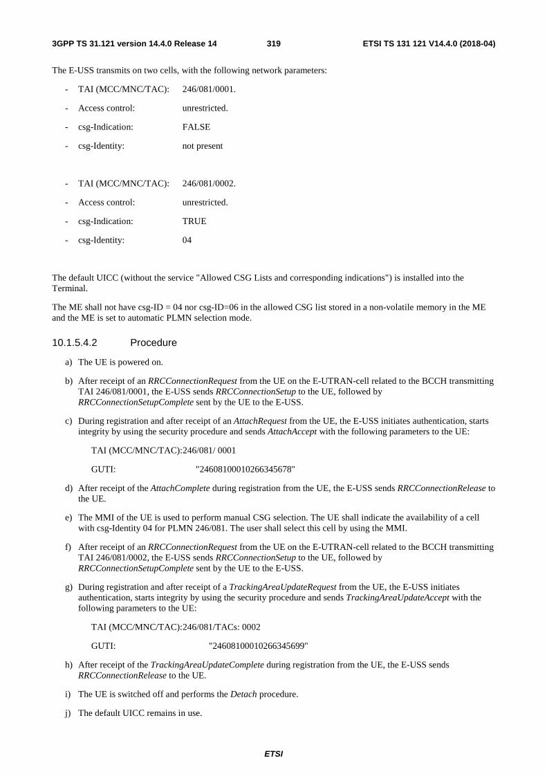
ETSI
ETSI TS 131 121 V14.4.0 (2018-04)3193GPP TS 31.121 version 14.4.0 Release 14
The E-USS transmits on two cells, with the following network parameters:
- TAI (MCC/MNC/TAC): 246/081/0001.
- Access control: unrestricted.
- csg-Indication: FALSE
- csg-Identity: not present
- TAI (MCC/MNC/TAC): 246/081/0002.
- Access control: unrestricted.
- csg-Indication: TRUE
- csg-Identity: 04
The default UICC (without the service "Allowed CSG Lists and corresponding indications") is installed into the Terminal.
The ME shall not have csg-ID = 04 nor csg-ID=06 in the allowed CSG list stored in a non-volatile memory in the ME and the ME is set to automatic PLMN selection mode.
10.1.5.4.2 Procedure
a) The UE is powered on.
b) After receipt of an RRCConnectionRequest from the UE on the E-UTRAN-cell related to the BCCH transmitting TAI 246/081/0001, the E-USS sends RRCConnectionSetup to the UE, followed by RRCConnectionSetupComplete sent by the UE to the E-USS.
c) During registration and after receipt of an AttachRequest from the UE, the E-USS initiates authentication, starts integrity by using the security procedure and sends AttachAccept with the following parameters to the UE:
TAI (MCC/MNC/TAC): 246/081/ 0001
GUTI: "24608100010266345678"
d) After receipt of the AttachComplete during registration from the UE, the E-USS sends RRCConnectionRelease to the UE.
e) The MMI of the UE is used to perform manual CSG selection. The UE shall indicate the availability of a cell with csg-Identity 04 for PLMN 246/081. The user shall select this cell by using the MMI.
f) After receipt of an RRCConnectionRequest from the UE on the E-UTRAN-cell related to the BCCH transmitting TAI 246/081/0002, the E-USS sends RRCConnectionSetup to the UE, followed by RRCConnectionSetupComplete sent by the UE to the E-USS.
g) During registration and after receipt of a TrackingAreaUpdateRequest from the UE, the E-USS initiates authentication, starts integrity by using the security procedure and sends TrackingAreaUpdateAccept with the following parameters to the UE:
TAI (MCC/MNC/TAC): 246/081/TACs: 0002
GUTI: "24608100010266345699"
h) After receipt of the TrackingAreaUpdateComplete during registration from the UE, the E-USS sends RRCConnectionRelease to the UE.
i) The UE is switched off and performs the Detach procedure.
j) The default UICC remains in use.

ETSI
ETSI TS 131 121 V14.4.0 (2018-04)3203GPP TS 31.121 version 14.4.0 Release 14
k) The E-USS shall change the BCCH for the cell transmitting TAI 246/081/0001 to the following network parameters:
- csg-Indication: TRUE
- csg-Identity: 06
l) The UE is powered on.
m) After receipt of an RRCConnectionRequest from the UE on the E-UTRAN-cell related to the BCCH transmitting TAI 246/081/0002, the E-USS sends RRCConnectionSetup to the UE, followed by RRCConnectionSetupComplete sent by the UE to the E-USS.
n) During registration and after receipt of an AttachRequest from the UE, the E-USS initiates authentication, starts integrity by using the security procedure and sends AttachReject to the UE with cause #25 (Not authorized for this CSG) with integrity protection, followed by RRCConnectionRelease.
o) The UE is soft powered down.
p) The default UICC remains in use.
q) The UE is powered on.
r) After 2 minutes the UE is soft powered down.
10.1.5.5 Acceptance criteria
1) After step a) the UE shall send an RRCConnectionRequest on the E-UTRAN-cell related to the BCCH transmitting TAI 246/081/0001 to the E-USS.
3) During step b) the terminal shall send AttachRequest to the E-USS.
4) After step c) the terminal shall respond with AttachComplete during registration.
5) During step e) the UE shall provide during the manual CSG selection the information for a cell with csg-Identity 04 for PLMN 246/081 to the user.
6) After step e) the UE shall send an RRCConnectionRequest on the E-UTRAN-cell related to the BCCH transmitting TAI 246/081/0002 to the E-USS.
7) During step f) the terminal shall send TrackingAreaUpdateRequest to the E-USS.
8) After step g) the terminal shall respond with TrackingAreaUpdateComplete during registration.
9) After step l) the UE shall send an RRCConnectionRequest on the E-UTRAN-cell related to the BCCH transmitting TAI 246/081/0002 to the E-USS.
10) During step n) the terminal shall send AttachRequest to the E-USS.
10a) After step n) the terminal shall not try to register to the E-USS using the same CSG ID which was rejected in step n).
11) After step q) the terminal shall not try to register to the E-USS using the same CSG ID which was rejected in step n).
10.1.6 CSG selection in E-UTRA with no CSG list on USIM, with IMSI change
10.1.6.1 Definition and applicability
A Closed Subscriber Group identifies subscribers of an operator who are permitted to access one or more cells of the PLMN but which have restricted access (CSG cells). A CSG cell is part of the PLMN, broadcasting a CSG indication

ETSI
ETSI TS 131 121 V14.4.0 (2018-04)3213GPP TS 31.121 version 14.4.0 Release 14
that is set to TRUE and a specific CSG identity. A CSG cell is accessible by the members of the closed subscriber group for that CSG identity. For a CSG cell, the UE shall check the broadcast CSG ID against the Allowed CSG list provided by NAS to check whether a CSG cell is suitable for the UE.
A UE supporting CSG selection selects CSG cell either automatically based on the list of allowed CSG identities or manually based on user selection of CSG on indication of list of available CSGs.
10.1.6.2 Conformance requirement
In manual CSG selection mode, the ME indicates to the user the list of available CSGs in the currently selected PLMN. The list of CSGs presented to the user is not restricted by the allowed CSG list.. If the MS supports CSG, it is provisioned with a list of allowed CSG identities and associated PLMN identities from the USIM if the list is available in the USIM.
If the UE supporting CSG selection has attempted manual CSG selection, the UE, when receiving the TRACKING AREA UPDATE ACCEPT message, shall check if the CSG ID of the cell where the UE has sent the TRACKING AREA UPDATE REQUEST message is contained in the Allowed CSG list. If not, the UE shall add that CSG ID to the Allowed CSG list. If the corresponding file is not present on the USIM, these EMM parameters except allowed CSG list are stored in a non-volatile memory in the ME together with the IMSI from the USIM. The allowed CSG list is stored in a non-volatile memory in the ME if the UE supports CSG selection. These EMM parameters can only be used if the IMSI from the USIM matches the IMSI stored in the non-volatile memory; else the UE shall delete the EMM parameters.
- TS 31.102 [4], subclauses 4.4.6.2 and 5.8.1;
- TS 23.122 [31], subclause 3.1A.
- TS 24.301 [26], subclause 5.5.3.2.4 and Annex C.
10.1.6.3 Test purpose
To verify that the ME adds the CSG ID to the Allowed CSG list in a non-volatile memory in the ME together with the IMSI from the USIM in case this CSG ID belongs to the cell where the ME has sent the TRACKING AREA UPDATE REQUEST message which was accepted by the E-USS as the corresponding file is not present on the simulated USIM. To verify that the ME removes this CSG ID stored in the Allowed CSG list available together with the IMSI after powered down and up in case the IMSI of the USIM has changed.
10.1.6.4 Method of test
10.1.6.4.1 Initial conditions
For this test an E-USS is required.
The E-USS transmits on two cells, with the following network parameters:
- TAI (MCC/MNC/TAC): 246/081/0001.
- Access control: unrestricted.
- csg-Indication: FALSE
- csg-Identity: not present
- TAI (MCC/MNC/TAC): 246/081/0002.
- Access control: unrestricted.

ETSI
ETSI TS 131 121 V14.4.0 (2018-04)3223GPP TS 31.121 version 14.4.0 Release 14
- csg-Indication: TRUE
- csg-Identity: 04
The default UICC (without the service "Allowed CSG Lists and corresponding indications") is installed into the Terminal.
The ME shall not have csg-ID = 04 nor csg-ID=06 in the allowed CSG list stored in a non-volatile memory in the ME and the ME is set to automatic PLMN selection mode.
10.1.6.4.2 Procedure
a) The UE is powered on.
b) After receipt of an RRCConnectionRequest from the UE on the E-UTRAN-cell related to the BCCH transmitting TAI 246/081/0001, the E-USS sends RRCConnectionSetup to the UE, followed by RRCConnectionSetupComplete sent by the UE to the E-USS.
c) During registration and after receipt of an AttachRequest from the UE, the E-USS initiates authentication, starts integrity by using the security procedure and sends AttachAccept with to the following parameters the UE:
TAI (MCC/MNC/TAC): 246/081/ 0001
GUTI: "24608100010266345678"
d) After receipt of the AttachComplete during registration from the UE, the E-USS sends RRCConnectionRelease to the UE.
e) The MMI of the UE is used to perform manual CSG selection. The UE shall indicate the availability of a cell with csg-Identity 04 for PLMN 246/081. The user shall select this cell by using the MMI.
f) After receipt of an RRCConnectionRequest from the UE on the E-UTRAN-cell related to the BCCH transmitting TAI 246/081/0002, the E-USS sends RRCConnectionSetup to the UE, followed by RRCConnectionSetupComplete sent by the UE to the E-USS.
g) During registration and after receipt of a TrackingAreaUpdateRequest from the UE, the E-USS initiates authentication, starts integrity by using the security procedure and sends TrackingAreaUpdateAccept with the following parameters to the UE:
TAI (MCC/MNC/TAC): 246/081/ 0002
GUTI: "24608100010266345699"
h) After receipt of the TrackingAreaUpdateComplete during registration from the UE, the E-USS sends RRCConnectionRelease to the UE.
i) The UE is switched off and performs the Detach procedure.
j) A new UICC with the following configuration is activated:
The default UICC with the following exception: The IMSI is set to "246081222233333".
k) The E-USS shall change the BCCH for the cell transmitting TAI 246/081/0001 to the following network parameters:
- csg-Indication: TRUE
- csg-Identity: 06
l) The UE is powered on.
m) After 2 minutes the UE is soft powered down.
10.1.6.5 Acceptance criteria

ETSI
ETSI TS 131 121 V14.4.0 (2018-04)3233GPP TS 31.121 version 14.4.0 Release 14
1) After step b) the UE shall send an RRCConnectionRequest on the E-UTRAN-cell related to the BCCH transmitting TAI 246/081/0001 to the e-USS.
3) During step b) the terminal shall send AttachRequest to the E-USS.
4) After step c) the terminal shall respond with AttachComplete during registration.
5) During step e) the UE shall provide during the manual CSG selection the information for a cell with csg-Identity 04 for PLMN 246/081 to the user.
6) After step e) the UE shall send an RRCConnectionRequest on the E-UTRAN-cell related to the BCCH transmitting TAI 246/081/0002 to the e-USS.
7) During step f) the terminal shall send TrackingAreaUpdateRequest to the E-USS.
8) After step g) the terminal shall respond with TrackingAreaUpdateComplete during registration.
9) After step l) the terminal shall not try to register to the E-USS.
10.1.7 Manual CSG selection without display restrictions in E-UTRA with ACSG list and OCSG list on USIM
10.1.7.1 Definition and applicability
A Closed Subscriber Group identifies subscribers of an operator who are permitted to access one or more cells of the PLMN but which have restricted access (CSG cells). A CSG cell is part of the PLMN, broadcasting a CSG indication that is set to TRUE and a specific CSG identity. A CSG cell is accessible by the members of the closed subscriber group for that CSG identity. For a CSG cell, the UE shall check the broadcast CSG ID against the Allowed CSG list provided by NAS to check whether a CSG cell is suitable for the UE.
A UE supporting CSG selection selects a CSG cell either automatically based on the list of allowed CSG identities or manually based on user selection of CSG on indication of list of available CSGs.
Editor's note: it is still being investigated whether the testing of Automatic CSG selection should be performed using a separate test case or an enhanced version of the Manual CSG selection test case.
10.1.7.2 Conformance requirement
The ME shall read the allowed CSG IDs from EFACSGL and EFOCSGL in order to perform HNB selection procedures. The lists in EFACSGL and EFOCSGL shall take precedence over the list stored in the ME non-volatile memory. If the MS supports CSG, it is provisioned with a list of allowed CSG identities and associated PLMN identities from the USIM if the list is available in the USIM.
If the UE supporting CSG selection has attempted manual CSG selection, the UE, when receiving the TRACKING AREA UPDATE ACCEPT message, shall check if the CSG ID of the cell where the UE has sent the TRACKING AREA UPDATE REQUEST message is contained in the Allowed CSG list. If not, the UE shall add that CSG ID to the Allowed CSG list EFACSGL. By default, the UE shall display all available CSGs for any PLMN, unless the UE has been configured by the HPLMN, for a specific PLMN, to display only CSGs in the Operator CSG List that are available.
- TS 31.102 [4], subclauses 4.2.18, 4.4.6.2, 4.4.6.5 and 5.8.1;
- TS 24.301 [26], subclause 5.5.3.2.4
- TS 22.220 [34], subclause 5.3.2 and 5.5.4
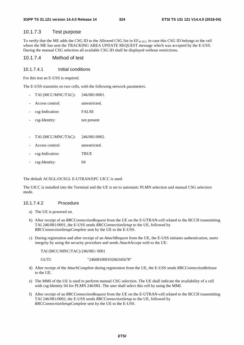
ETSI
ETSI TS 131 121 V14.4.0 (2018-04)3243GPP TS 31.121 version 14.4.0 Release 14
10.1.7.3 Test purpose
To verify that the ME adds the CSG ID to the Allowed CSG list in EFACSGL in case this CSG ID belongs to the cell where the ME has sent the TRACKING AREA UPDATE REQUEST message which was accepted by the E-USS. During the manual CSG selection all available CSG ID shall be displayed without restrictions.
10.1.7.4 Method of test
10.1.7.4.1 Initial conditions
For this test an E-USS is required.
The E-USS transmits on two cells, with the following network parameters:
- TAI (MCC/MNC/TAC): 246/081/0001.
- Access control: unrestricted.
- csg-Indication: FALSE
- csg-Identity: not present
- TAI (MCC/MNC/TAC): 246/081/0002.
- Access control: unrestricted.
- csg-Indication: TRUE
- csg-Identity: 04
The default ACSGL/OCSGL E-UTRAN/EPC UICC is used.
The UICC is installed into the Terminal and the UE is set to automatic PLMN selection and manual CSG selection mode.
10.1.7.4.2 Procedure
a) The UE is powered on.
b) After receipt of an RRCConnectionRequest from the UE on the E-UTRAN-cell related to the BCCH transmitting TAI 246/081/0001, the E-USS sends RRCConnectionSetup to the UE, followed by RRCConnectionSetupComplete sent by the UE to the E-USS.
c) During registration and after receipt of an AttachRequest from the UE, the E-USS initiates authentication, starts integrity by using the security procedure and sends AttachAccept with to the UE:
TAI (MCC/MNC/TAC): 246/081/ 0001
GUTI: "24608100010266345678"
d) After receipt of the AttachComplete during registration from the UE, the E-USS sends RRCConnectionRelease to the UE.
e) The MMI of the UE is used to perform manual CSG selection. The UE shall indicate the availability of a cell with csg-Identity 04 for PLMN 246/081. The user shall select this cell by using the MMI.
f) After receipt of an RRCConnectionRequest from the UE on the E-UTRAN-cell related to the BCCH transmitting TAI 246/081/0002, the E-USS sends RRCConnectionSetup to the UE, followed by RRCConnectionSetupComplete sent by the UE to the E-USS.

ETSI
ETSI TS 131 121 V14.4.0 (2018-04)3253GPP TS 31.121 version 14.4.0 Release 14
g) During registration and after receipt of a TrackingAreaUpdateRequest from the UE, the E-USS initiates authentication, starts integrity by using the security procedure and sends TrackingAreaUpdateAccept with to the UE:
TAI (MCC/MNC/TAC): 246/081/ 0002
GUTI: "24608100010266436599"
h) After receipt of the TrackingAreaUpdatComplete during registration from the UE, the E-USS sends RRCConnectionRelease to the UE.
i) The UE is soft powered down.
10.1.7.5 Acceptance criteria
1) After step b) the UE shall send an RRCConnectionRequest on the E-UTRAN-cell related to the BCCH transmitting TAI 246/081/0001 to the e-USS.
3) During step b) the terminal shall send AttachRequest to the E-USS.
4) After step c) the terminal shall respond with AttachComplete during registration.
5) During step e) the UE shall provide during the manual CSG selection the information for a cell with csg-Identity 04 for PLMN 246/081 to the user.
6) After step e) the UE shall send an RRCConnectionRequest on the E-UTRAN-cell related to the BCCH transmitting TAI 246/081/0002 to the E-USS.
7) During step f) the terminal shall send TrackingAreaUpdateRequest to the E-USS.
8) After step g) the terminal shall respond with TrackingAreaUpdatComplete during registration.
9) After step i) the USIM shall contain the following values:
EFEPSLOCI (EPS Information)
Logically: GUTI: 24608100010266436599 Last visited registered TAI: 246/081/0002 EPS update status: updated
Coding: B1 B2 B3 B4 B5 B6 B7 B8 B9 B10 B11 Hex 0B F6 42 16 80 00 01 02 66 43 65 B12 B13 B14 B15 B16 B17 B18 99 42 16 80 00 02 00
EFACSGL (Allowed CSG Lists)
Logically:
1st CSG list
PLMN: 246 081 (MCC MNC) 1st CSG list 1st CSG Type indication 02 1st CSG list 1st CSG HNB Name indication 02 1st CSG list 1st CSG CSG ID: 02 (27bit) 1st CSG list 2nd CSG Type indication 03 1st CSG list 2nd CSG HNB Name indication 03 1st CSG list 2nd CSG CSG ID: 03 (27bit) 1st CSG list 3rd CSG Type indication 'xx' (not checked) 1st CSG list 3rd CSG HNB Name indication 'xx' (not checked) 1st CSG list 3rd CSG CSG ID: 04 (27bit)

ETSI
ETSI TS 131 121 V14.4.0 (2018-04)3263GPP TS 31.121 version 14.4.0 Release 14
Coding: A0 1D 80 03 42 16 80 81 06 02 02 00 00 00 5F 81 06 03 03 00 00 00 7F 81 06 xx xx 00 00 00 9F
2nd CSG list
PLMN: 244 081 (MCC MNC) 2nd CSG list 1st CSG Type indication 08 2nd CSG list 1st CSG HNB Name indication 08 2nd CSG list 1st CSG CSG ID: 08 (27bit)
Coding: A0 0D 80 03 42 14 80 81 06 08 08 00 00 01 1F
Note: The 1st and 2nd CSG list may be stored together or separately in any record in arbitrary order.
EFOCSGL (Operator CSG Lists)
Unchanged values as defined in 4.6.3
10.1.8 Manual CSG selection with display restrictions in E-UTRA with ACSG list and OCSG list on USIM
10.1.8.1 Definition and applicability
A Closed Subscriber Group identifies subscribers of an operator who are permitted to access one or more cells of the PLMN but which have restricted access (CSG cells). A CSG cell is part of the PLMN, broadcasting a CSG indication that is set to TRUE and a specific CSG identity. A CSG cell is accessible by the members of the closed subscriber group for that CSG identity. For a CSG cell, the UE shall check the broadcast CSG ID against the Allowed CSG list provided by NAS to check whether a CSG cell is suitable for the UE.
A UE supporting CSG selection selects a CSG cell either automatically based on the list of allowed CSG identities or manually based on user selection of CSG on indication of list of available CSGs.
10.1.8.2 Conformance requirement
The ME shall read the allowed CSG IDs from EFACSGL and EFOCSGL in order to perform HNB selection procedures. The lists in EFACSGL and EFOCSGL shall take precedence over the list stored in the ME non-volatile memory. If the MS supports CSG, it is provisioned with a list of allowed CSG identities and associated PLMN identities from the USIM if the list is available in the USIM.
If the UE supporting CSG selection has attempted manual CSG selection, the UE, when receiving the TRACKING AREA UPDATE ACCEPT message, shall check if the CSG ID of the cell where the UE has sent the TRACKING AREA UPDATE REQUEST message is contained in the Allowed CSG list. If not, the UE shall add that CSG ID to the Allowed CSG list EFACSGL. By default, the UE shall display all available CSGs for any PLMN, unless the UE has been configured by the HPLMN, for a specific PLMN, to display only CSGs in the Operator CSG List that are available.
- TS 31.102 [4], subclauses 4.2.18, 4.4.6.2, 4.4.6.5 and 5.8.1;
- TS 24.301 [26], subclause 5.5.3.2.4
- TS 22.220 [34], subclause 5.3.2 and 5.5.4

ETSI
ETSI TS 131 121 V14.4.0 (2018-04)3273GPP TS 31.121 version 14.4.0 Release 14
10.1.8.3 Test purpose
To verify that the ME adds the CSG ID to the Allowed CSG list in EFACSGL in case this CSG ID belongs to the cell where the ME has sent the TRACKING AREA UPDATE REQUEST message which was accepted by the E-USS. During the manual CSG selection all available CSG ID shall be displayed with restrictions.
10.1.8.4 Method of test
10.1.8.4.1 Initial conditions
For this test an E-USS is required.
The E-USS transmits on two cells, with the following network parameters:
- TAI (MCC/MNC/TAC): 246/081/0001.
- Access control: unrestricted.
- csg-Indication: FALSE
- csg-Identity: not present
- TAI (MCC/MNC/TAC): 246/080/0002.
- Access control: unrestricted.
- csg-Indication: TRUE
- csg-Identity: 04
The default ACSGL/OCSGL E-UTRAN/EPC UICC is used except the following change:
EFAD (Administrative Data)
Logically: Normal operation + specific facilities Ciphering indicator feature disabled MNC: 3 digit
For every PLMN not included in EF_OCSGL or any PLMN for which a CSG display indicator tag is not present, only the available CSGs found in the Operator CSG list shall be displayed (B3)
Coding: B1 B2 B3 B4 Hex 01 00 02 03
The UICC is installed into the Terminal and the UE is set to automatic PLMN selection and manual CSG selection mode.
10.1.8.4.2 Procedure
a) The UE is powered on.
b) After receipt of an RRCConnectionRequest from the UE on the E-UTRAN-cell related to the BCCH transmitting TAI 246/081/0001, the E-USS sends RRCConnectionSetup to the UE, followed by RRCConnectionSetupComplete sent by the UE to the E-USS.

ETSI
ETSI TS 131 121 V14.4.0 (2018-04)3283GPP TS 31.121 version 14.4.0 Release 14
c) During registration and after receipt of an AttachRequest from the UE, the E-USS initiates authentication, starts integrity by using the security procedure and sends AttachAccept with to the UE:
TAI (MCC/MNC/TAC): 246/081/ 0001
GUTI: "24608100010266345678"
d) After receipt of the AttachComplete during registration from the UE, the E-USS sends RRCConnectionRelease to the UE.
e) The MMI of the UE is used to perform manual CSG selection. The UE shall not indicate the availability of a cell with csg-Identity 04 for PLMN 246/080, this shall be verified for 2 minutes.
f) The E-USS stops all RF output for the first cell with TAI 246/081/0001 on the BCCH. The BCCH is changed to contain:
- TAI (MCC/MNC/TAC): 246/081/0002
- csg-Indication: TRUE
- csg-Identity: 04
The E-USS then resumes RF output on the BCCH.
g) The MMI of the UE is used to perform manual CSG selection. The UE shall indicate the availability of a cell with csg-Identity 04 for PLMN 246/081. The user shall select this cell by using the MMI.
h) After receipt of an RRCConnectionRequest from the UE on the E-UTRAN-cell related to the BCCH transmitting TAI 246/081/0002, the E-USS sends RRCConnectionSetup to the UE, followed by RRCConnectionSetupComplete sent by the UE to the E-USS.
i) During registration and after receipt of a TrackingAreaUpdateRequest from the UE, the E-USS initiates authentication, starts integrity by using the security procedure and sends TrackingAreaUpdateAccept with to the UE:
TAI (MCC/MNC/TAC): 246/081/ 0002
GUTI: "24608100010266436599"
j) After receipt of the TrackingAreaUpdatComplete during registration from the UE, the E-USS sends RRCConnectionRelease to the UE.
k) The UE is soft powered down.
10.1.8.5 Acceptance criteria
1) After step b) the UE shall send an RRCConnectionRequest on the E-UTRAN-cell related to the BCCH transmitting TAI 246/081/0001 to the E-USS.
2) During step b) the terminal shall send AttachRequest to the E-USS.
3) After step c) the terminal shall respond with AttachComplete during registration.
4) During step e) the UE shall not provide during the manual CSG selection the information for a cell with csg-Identity 04 for PLMN 246/080 to the user.
5) During step g) the UE shall provide during the manual CSG selection the information for a cell with csg-Identity 04 for PLMN 246/081 to the user.
6) After step h) the UE shall send an RRCConnectionRequest on the E-UTRAN-cell related to the BCCH transmitting TAI 246/081/0002 to the E-USS.
7) During step i) the terminal shall send TrackingAreaUpdateRequest to the E-USS.
8) After step j) the terminal shall respond with TrackingAreaUpdatComplete during registration.
9) After step k) the USIM shall contain the following values:

ETSI
ETSI TS 131 121 V14.4.0 (2018-04)3293GPP TS 31.121 version 14.4.0 Release 14
EFEPSLOCI (EPS Information)
Logically: GUTI: 24608100010266436599 Last visited registered TAI: 246/081/0002 EPS update status: updated
Coding: B1 B2 B3 B4 B5 B6 B7 B8 B9 B10 B11 Hex 0B F6 42 16 80 00 01 02 66 43 65 B12 B13 B14 B15 B16 B17 B18 99 42 16 80 00 02 00
EFACSGL (Allowed CSG Lists)
Logically:
1st CSG list
PLMN: 246 081 (MCC MNC) 1st CSG list 1st CSG Type indication 02 1st CSG list 1st CSG HNB Name indication 02 1st CSG list 1st CSG CSG ID: 02 (27bit) 1st CSG list 2nd CSG Type indication 03 1st CSG list 2nd CSG HNB Name indication 03 1st CSG list 2nd CSG CSG ID: 03 (27bit) 1st CSG list 3rd CSG Type indication 'xx' (not checked) 1st CSG list 3rd CSG HNB Name indication 'xx' (not checked) 1st CSG list 3rd CSG CSG ID: 04 (27bit)
Coding: A0 1D 80 03 42 16 80 81 06 02 02 00 00 00 5F 81 06 03 03 00 00 00 7F 81 06 xx xx 00 00 00 9F
2nd CSG list
PLMN: 244 081 (MCC MNC) 2nd CSG list 1st CSG Type indication 08 2nd CSG list 1st CSG HNB Name indication 08 2nd CSG list 1st CSG CSG ID: 08 (27bit)
Coding: A0 0D 80 03 42 14 80 81 06 08 08 00 00 01 1F
Note: The 1st and 2nd CSG list may be stored together or separately in any record in arbitrary order.
EFOCSGL (Operator CSG Lists)
Unchanged values as defined in 4.6.3
10.2 CSG list handling for UTRA

ETSI
ETSI TS 131 121 V14.4.0 (2018-04)3303GPP TS 31.121 version 14.4.0 Release 14
10.2.1 Manual CSG selection without display restrictions in UTRA with ACSG list and OCSG list on USIM
10.2.1.1 Definition and applicability
A Closed Subscriber Group identifies subscribers of an operator who are permitted to access one or more cells of the PLMN but which have restricted access (CSG cells). A CSG cell is part of the PLMN, broadcasting a CSG indication that is set to TRUE and a specific CSG identity. A CSG cell is accessible by the members of the closed subscriber group for that CSG identity. For a CSG cell, the UE shall check the broadcast CSG ID against the Allowed CSG list provided by NAS to check whether a CSG cell is suitable for the UE.
A UE supporting CSG selection selects a CSG cell either automatically based on the list of allowed CSG identities or manually based on user selection of CSG on indication of list of available CSGs.
Editor's note: it is still being investigated whether the testing of Automatic CSG selection should be performed using a separate test case or an enhanced version of the Manual CSG selection test case.
10.2.1.2 Conformance requirement
The ME shall read the allowed CSG IDs from EFACSGL and EFOCSGL in order to perform HNB selection procedures. The lists in EFACSGL and EFOCSGL shall take precedence over the list stored in the ME non-volatile memory. If the MS supports CSG, it is provisioned with a list of allowed CSG identities and associated PLMN identities from the USIM if the list is available in the USIM.
If the UE supporting CSG selection has attempted manual CSG selection, the UE, when receiving the ROUTING AREA UPDATE ACCEPT message, shall check if the CSG ID of the cell where the UE has sent the ROUTING AREA UPDATE REQUEST message is contained in the Allowed CSG list. If not, the UE shall add that CSG ID to the Allowed CSG list EFACSGL. By default, the UE shall display all available CSGs for any PLMN, unless the UE has been configured by the HPLMN, for a specific PLMN, to display only CSGs in the Operator CSG List that are available.
- TS 31.102 [4], subclauses 4.2.18, 4.4.6.2, 4.4.6.5 and 5.8.1;
- TS 23.122 [31], subclause 3.1A.
- TS 22.220 [34], subclause 5.3.2 and 5.5.4
10.2.1.3 Test purpose
To verify that the ME adds the CSG ID to the Allowed CSG list in EFACSGL in case this CSG ID belongs to the cell where the ME has sent the ROUTING AREA UPDATE REQUEST message which was accepted by the USS. During the manual CSG selection all available CSG ID shall be displayed without restrictions.
10.2.1.4 Method of test
10.2.1.4.1 Initial conditions
For this test an USS is required.
The USS transmits on two cells, with the following network parameters:
- RAI (MCC/MNC/LAC/RAC): 246/081/0001/01.
- Access control: unrestricted.
- csg-Indication: FALSE
- csg-Identity: not present

ETSI
ETSI TS 131 121 V14.4.0 (2018-04)3313GPP TS 31.121 version 14.4.0 Release 14
- RAI (MCC/MNC/LAC/RAC): 246/081/0002/02.
- Access control: unrestricted.
- csg-Indication: TRUE
- csg-Identity: 04
The default ACSGL/OCSGL E-UTRAN/EPC UICC is used.
The UICC is installed into the Terminal and the UE is set to automatic PLMN selection and manual CSG selection mode.
10.2.1.4.2 Procedure
a) The UE is powered on.
b) After receipt of an RRCConnectionRequest from the UE on the UTRAN-cell related to the BCCH transmitting RAI 246/081/0001/01, the USS sends RRCConnectionSetup to the UE, followed by RRCConnectionSetupComplete sent by the UE to the USS.
c) During registration and after receipt of an AttachRequest from the UE, the USS initiates authentication, starts integrity by using the security procedure and sends AttachAccept with to the UE:
RAI (MCC/MNC/LAC/RAC): 246/081/0001/01
P-TMSI "87512890"
d) After receipt of the AttachComplete during registration from the UE, the USS sends RRCConnectionRelease to the UE.
e) The MMI of the UE is used to perform manual CSG selection. The UE shall indicate the availability of a cell with csg-Identity 04 for PLMN 246/081. The user shall select this cell by using the MMI.
f) After receipt of an RRCConnectionRequest from the UE on the UTRAN-cell related to the BCCH transmitting RAI 246/081/0002/02, the USS sends RRCConnectionSetup to the UE, followed by RRCConnectionSetupComplete sent by the UE to the USS.
g) During registration and after receipt of a RoutingAreaUpdateRequest from the UE, the USS initiates authentication, starts integrity by using the security procedure and sends RoutingAreaUpdateAccept with to the UE:
RAI (MCC/MNC/LAC/RAC): 246/081/0002/02
P-TMSI "34567890"
h) After receipt of the TrackingAreaUpdatComplete during registration from the UE, the USS sends RRCConnectionRelease to the UE.
i) The UE is soft powered down.
10.2.1.5 Acceptance criteria
1) After step b) the UE shall send an RRCConnectionRequest on the UTRAN-cell related to the BCCH transmitting RAI 246/081/0001/01 to the USS.
3) During step C) the terminal shall send AttachRequest to the USS.
4) After step c) the terminal shall respond with AttachComplete during registration.
5) During step e) the UE shall provide during the manual CSG selection the information for a cell with csg-Identity 04 for PLMN 246/081 to the user.

ETSI
ETSI TS 131 121 V14.4.0 (2018-04)3323GPP TS 31.121 version 14.4.0 Release 14
6) After step e) the UE shall send an RRCConnectionRequest on the UTRAN-cell related to the BCCH transmitting RAI 246/081/0002/02 to the USS.
7) During step g) the terminal shall send RoutingAreaUpdateRequest to the USS.
8) After step g) the terminal shall respond with RoutingAreaUpdatComplete during registration.
9) After step i) the USIM shall contain the following values:
EFPSLOCI (Location Information)
Logically: RAI-MCC: 246 RAI-MNC: 081 RAI-LAC: 0002 RAI-RAC: 02 P-TMSI: "34567890"
Coding: B1 B2 B3 B4 B5 B6 B7 B8 B9 B10 B11 Hex 34 56 78 90 xx xx xx 42 16 80 00 Coding: B12 B13 B14 Hex 02 02 00
EFACSGL (Allowed CSG Lists)
Logically:
1st CSG list
PLMN: 246 081 (MCC MNC) 1st CSG list 1st CSG Type indication 02 1st CSG list 1st CSG HNB Name indication 02 1st CSG list 1st CSG CSG ID: 02 (27bit) 1st CSG list 2nd CSG Type indication 03 1st CSG list 2nd CSG HNB Name indication 03 1st CSG list 2nd CSG CSG ID: 03 (27bit) 1st CSG list 3rd CSG Type indication 'xx' (not checked) 1st CSG list 3rd CSG HNB Name indication 'xx' (not checked) 1st CSG list 3rd CSG CSG ID: 04 (27bit)
Coding: A0 1D 80 03 42 16 80 81 06 02 02 00 00 00 5F 81 06 03 03 00 00 00 7F 81 06 xx xx 00 00 00 9F
2nd CSG list
PLMN: 244 081 (MCC MNC) 2nd CSG list 1st CSG Type indication 08 2nd CSG list 1st CSG HNB Name indication 08 2nd CSG list 1st CSG CSG ID: 08 (27bit)
Coding: A0 0D 80 03 42 14 80 81 06 08 08 00 00 01 1F
Note: The 1st and 2nd CSG list may be stored together or separately in any record in arbitrary order.

ETSI
ETSI TS 131 121 V14.4.0 (2018-04)3333GPP TS 31.121 version 14.4.0 Release 14
EFOCSGL (Operator CSG Lists)
Unchanged values as defined in 4.6.3
10.2.2 Manual CSG selection with display restrictions in UTRA with ACSG list and OCSG list on USIM
10.2.2.1 Definition and applicability
A Closed Subscriber Group identifies subscribers of an operator who are permitted to access one or more cells of the PLMN but which have restricted access (CSG cells). A CSG cell is part of the PLMN, broadcasting a CSG indication that is set to TRUE and a specific CSG identity. A CSG cell is accessible by the members of the closed subscriber group for that CSG identity. For a CSG cell, the UE shall check the broadcast CSG ID against the Allowed CSG list provided by NAS to check whether a CSG cell is suitable for the UE.
A UE supporting CSG selection selects a CSG cell either automatically based on the list of allowed CSG identities or manually based on user selection of CSG on indication of list of available CSGs.
10.2.2.2 Conformance requirement
The ME shall read the allowed CSG IDs from EFACSGL and EFOCSGL in order to perform HNB selection procedures. The lists in EFACSGL and EFOCSGL shall take precedence over the list stored in the ME non-volatile memory. If the MS supports CSG, it is provisioned with a list of allowed CSG identities and associated PLMN identities from the USIM if the list is available in the USIM.
If the UE supporting CSG selection has attempted manual CSG selection, the UE, when receiving the ROUTING AREA UPDATE ACCEPT message, shall check if the CSG ID of the cell where the UE has sent the ROUTING AREA UPDATE REQUEST message is contained in the Allowed CSG list. If not, the UE shall add that CSG ID to the Allowed CSG list EFACSGL. By default, the UE shall display all available CSGs for any PLMN, unless the UE has been configured by the HPLMN, for a specific PLMN, to display only CSGs in the Operator CSG List that are available.
- TS 31.102 [4], subclauses 4.2.18, 4.4.6.2, 4.4.6.5 and 5.8.1;
- TS 23.122 [31], subclause 3.1A.
- TS 22.220 [34], subclause 5.3.2 and 5.5.4
10.2.2.3 Test purpose
To verify that the ME adds the CSG ID to the Allowed CSG list in EFACSGL in case this CSG ID belongs to the cell where the ME has sent the ROUTING AREA UPDATE REQUEST message which was accepted by the USS. During the manual CSG selection all available CSG ID shall be displayed with restrictions.
10.2.2.4 Method of test
10.2.2.4.1 Initial conditions
For this test an USS is required.
The USS transmits on two cells, with the following network parameters:
- RAI (MCC/MNC/LAC/RAC): 246/081/0001/01.

ETSI
ETSI TS 131 121 V14.4.0 (2018-04)3343GPP TS 31.121 version 14.4.0 Release 14
- Access control: unrestricted.
- csg-Indication: FALSE
- csg-Identity: not present
- RAI (MCC/MNC/LAC/RAC): 246/080/0002/02.
- Access control: unrestricted.
- csg-Indication: TRUE
- csg-Identity: 04
The default ACSGL/OCSGL E-UTRAN/EPC UICC is used except the following change:
EFAD (Administrative Data)
Logically: Normal operation + specific facilities Ciphering indicator feature disabled MNC: 3 digit
For every PLMN not included in EF_OCSGL or any PLMN for which a CSG display indicator tag is not present, only the available CSGs found in the Operator CSG list shall be displayed (B3)
Coding: B1 B2 B3 B4 Hex 01 00 02 03
.
The UICC is installed into the Terminal and the UE is set to automatic PLMN selection and manual CSG selection mode.
10.2.2.4.2 Procedure
a) The UE is powered on.
b) After receipt of an RRCConnectionRequest from the UE on the UTRAN-cell related to the BCCH transmitting RAI 246/081/0001/01, the USS sends RRCConnectionSetup to the UE, followed by RRCConnectionSetupComplete sent by the UE to the USS.
c) During registration and after receipt of an AttachRequest from the UE, the USS initiates authentication, starts integrity by using the security procedure and sends AttachAccept with to the UE:
RAI (MCC/MNC/LAC/RAC): 246/081/0001/01
P-TMSI "87512890"
d) After receipt of the AttachComplete during registration from the UE, the USS sends RRCConnectionRelease to the UE.
e) The MMI of the UE is used to perform manual CSG selection. The UE shall not indicate the availability of a cell with csg-Identity 04 for PLMN 246/080, this shall be verified for 2 minutes.
f) The USS stops all RF output for the first cell with RAI 246/081/0001/01 on the BCCH. The BCCH is changed to contain:
- RAI (MCC/MNC/LAC/RAC): 246/081/0002/02.
- csg-Indication: TRUE
- csg-Identity: 04
The USS then resumes RF output on the BCCH.

ETSI
ETSI TS 131 121 V14.4.0 (2018-04)3353GPP TS 31.121 version 14.4.0 Release 14
g) The MMI of the UE is used to perform manual CSG selection. The UE shall indicate the availability of a cell with csg-Identity 04 for PLMN 246/081. The user shall select this cell by using the MMI.
h) After receipt of an RRCConnectionRequest from the UE on the UTRAN-cell related to the BCCH transmitting RAI 246/081/0002/02, the USS sends RRCConnectionSetup to the UE, followed by RRCConnectionSetupComplete sent by the UE to the USS.
i) During registration and after receipt of a RoutingAreaUpdateRequest from the UE, the USS initiates authentication, starts integrity by using the security procedure and sends RoutingAreaUpdateAccept with to the UE:
RAI (MCC/MNC/TAC): 246/081/0002/02
P-TMSI "34567890"
j) After receipt of the RoutingAreaUpdatComplete during registration from the UE, the USS sends RRCConnectionRelease to the UE.
k) The UE is soft powered down.
10.2.2.5 Acceptance criteria
1.) After step b) the UE shall send an RRCConnectionRequest on the UTRAN-cell related to the BCCH transmitting RAI 246/081/0001/01 to the USS.
3) During step c) the terminal shall send AttachRequest to the USS.
4) After step c) the terminal shall respond with AttachComplete during registration.
5) During step e) the UE shall not provide during the manual CSG selection the information for a cell with csg-Identity 04 for PLMN 246/080 to the user.
6) During step g) the UE shall provide during the manual CSG selection the information for a cell with csg-Identity 04 for PLMN 246/081 to the user.
6a) After step g) the UE shall send an RRCConnectionRequest on the UTRAN-cell related to the BCCH transmitting RAI 246/081/0002/02 to the USS.
7) During step i) the terminal shall send RoutingAreaUpdateRequest to the USS.
8) After step i) the terminal shall respond with RoutingAreaUpdatComplete during registration.
9) After step k) the USIM shall contain the following values:
EFPSLOCI (Location Information)
Logically: RAI-MCC: 246 RAI-MNC: 081 RAI-LAC: 0002 RAI-RAC: 02 P-TMSI: "34567890"
Coding: B1 B2 B3 B4 B5 B6 B7 B8 B9 B10 B11 Hex 34 56 78 90 xx xx xx 42 16 80 00 Coding: B12 B13 B14 Hex 02 02 00
EFACSGL (Allowed CSG Lists)
Logically:
1st CSG list

ETSI
ETSI TS 131 121 V14.4.0 (2018-04)3363GPP TS 31.121 version 14.4.0 Release 14
PLMN: 246 081 (MCC MNC) 1st CSG list 1st CSG Type indication 02 1st CSG list 1st CSG HNB Name indication 02 1st CSG list 1st CSG CSG ID: 02 (27bit) 1st CSG list 2nd CSG Type indication 03 1st CSG list 2nd CSG HNB Name indication 03 1st CSG list 2nd CSG CSG ID: 03 (27bit) 1st CSG list 3rd CSG Type indication 'xx' (not checked) 1st CSG list 3rd CSG HNB Name indication 'xx' (not checked) 1st CSG list 3rd CSG CSG ID: 04 (27bit)
Coding: A0 1D 80 03 42 16 80 81 06 02 02 00 00 00 5F 81 06 03 03 00 00 00 7F 81 06 xx xx 00 00 00 9F
2nd CSG list
PLMN: 244 081 (MCC MNC) 2nd CSG list 1st CSG Type indication 08 2nd CSG list 1st CSG HNB Name indication 08 2nd CSG list 1st CSG CSG ID: 08 (27bit)
Coding: A0 0D 80 03 42 14 80 81 06 08 08 00 00 01 1F
Note: The 1st and 2nd CSG list may be stored together or separately in any record in arbitrary order.
EFOCSGL (Operator CSG Lists)
Unchanged values as defined in 4.6.3
10.2.3 Manual CSG selection in UTRA with CSG list on USIM, success
10.2.3.1 Definition and applicability
A Closed Subscriber Group identifies subscribers of an operator who are permitted to access one or more cells of the PLMN but which have restricted access (CSG cells). A CSG cell is part of the PLMN, broadcasting a CSG indication that is set to TRUE and a specific CSG identity. A CSG cell is accessible by the members of the closed subscriber group for that CSG identity. For a CSG cell, the UE shall check the broadcast CSG ID against the Allowed CSG list provided by NAS to check whether a CSG cell is suitable for the UE.
A UE supporting CSG selection selects CSG cell either automatically based on the list of allowed CSG identities or manually based on user selection of CSG on indication of list of available CSGs.
Editor's note: it is still being investigated whether the testing of both the unsuccessful Manual CSG selection and the Automatic CSG selection should be performed using a separate test case or an enhanced version of the Manual CSG selection test case.
10.2.3.2 Conformance requirement
The ME shall read the allowed CSG IDs from EFACSGL in order to perform HNB selection procedures. The lists in EFACSGL shall take precedence over the list stored in the ME non-volatile memory. In manual CSG selection mode, the ME indicates to the user the list of available CSGs in the currently selected PLMN. The list of CSGs presented to the user is not restricted by the allowed CSG list.

ETSI
ETSI TS 131 121 V14.4.0 (2018-04)3373GPP TS 31.121 version 14.4.0 Release 14
If the MS supports CSG, it is provisioned with a list of allowed CSG identities and associated PLMN identities from the USIM if the list is available in the USIM.
If the UE supporting CSG selection has attempted manual CSG selection, the UE, when receiving the ROUTING AREA UPDATE ACCEPT message, shall check if the CSG ID of the cell where the UE has sent the ROUTING AREA UPDATE REQUEST message is contained in the Allowed CSG list. If not, the UE shall add that CSG ID to the Allowed CSG list.
- TS 31.102 [4], subclauses 4.4.6.2 and 5.8.1;
- TS 23.122 [31], subclause 3.1A.
- TS 24.008 [16], subclause 4.7.5.1.3
10.2.3.3 Test purpose
To verify that the ME adds the CSG ID to the Allowed CSG list in EFACSGL in case this CSG ID belongs to the cell where the ME has sent the ROUTING AREA UPDATE REQUEST message which was accepted by the USS.
10.2.3.4 Method of test
10.2.3.4.1 Initial conditions
For this test an USS is required.
The USS transmits on two cells, with the following network parameters:
- RAI (MCC/MNC/LAC/RAC): 246/081/0001/01.
- Access control: unrestricted.
- csg-Indication: FALSE
- csg-Identity: not present
- RAI (MCC/MNC/LAC/RAC): 246/081/0002/02.
- Access control: unrestricted.
- csg-Indication: TRUE
- csg-Identity: 04
The default E-UTRAN UICC is used.
The UICC is installed into the Terminal and the UE is set to automatic PLMN selection mode.
10.2.3.4.2 Procedure
a) The UE is powered on.
b) After receipt of an RRCConnectionRequest from the UE on the UTRAN-cell related to the BCCH transmitting RAI 246/081/0001/01, the USS sends RRCConnectionSetup to the UE, followed by RRCConnectionSetupComplete sent by the UE to the USS.
c) During registration and after receipt of an AttachRequest from the UE, the USS initiates authentication, starts integrity by using the security procedure and sends AttachAccept with to the UE:
RAI (MCC/MNC/LAC/RAC): 246/081/0001/01

ETSI
ETSI TS 131 121 V14.4.0 (2018-04)3383GPP TS 31.121 version 14.4.0 Release 14
P-TMSI "87512890"
d) After receipt of the AttachComplete during registration from the UE, the USS sends RRCConnectionRelease to the UE.
e) The MMI of the UE is used to perform manual CSG selection. The UE shall indicate the availability of a cell with csg-Identity 04 for PLMN 246/081. The user shall select this cell by using the MMI.
f) After receipt of an RRCConnectionRequest from the UE on the UTRAN-cell related to the BCCH transmitting RAI 246/081/0002/02, the USS sends RRCConnectionSetup to the UE, followed by RRCConnectionSetupComplete sent by the UE to the USS.
g) During registration and after receipt of a RoutingAreaUpdateRequest from the UE, the USS initiates authentication, starts integrity by using the security procedure and sends RoutingAreaUpdateAccept with to the UE:
RAI (MCC/MNC/LAC/RAC): 246/081/0002/02
P-TMSI "34567890"
h) After receipt of the RoutingAreaUpdatComplete during registration from the UE, the USS sends RRCConnectionRelease to the UE.
i) The UE is soft powered down.
10.2.3.5 Acceptance criteria
1) After step a) the UE shall send an RRCConnectionRequest on the UTRAN-cell related to the BCCH transmitting RAI 246/081/0001/01 to the USS.
3) During step c) the terminal shall send AttachRequest to the USS.
4) After step c) the terminal shall respond with AttachComplete during registration.
5) During step e) the UE shall provide during the manual CSG selection the information for a cell with csg-Identity 04 for PLMN 246/081 to the user.
6) After step e) the UE shall send an RRCConnectionRequest on the UTRAN-cell related to the BCCH transmitting RAI 246/081/0002/02 to the USS.
7) During step g) the terminal shall send RoutingAreaUpdateRequest to the USS.
8) After step g) the terminal shall respond with RoutingAreaUpdatComplete during registration.
9) After step i) the USIM shall contain the following values:
EFPSLOCI (Location Information)
Logically: RAI-MCC: 246 RAI-MNC: 081 RAI-LAC: 0002 RAI-RAC: 02 P-TMSI: "34567890"
Coding: B1 B2 B3 B4 B5 B6 B7 B8 B9 B10 B11 Hex 34 56 78 90 xx xx xx 42 16 80 00 Coding: B12 B13 B14 Hex 02 02 00
EFACSGL (Allowed CSG Lists)
Logically:

ETSI
ETSI TS 131 121 V14.4.0 (2018-04)3393GPP TS 31.121 version 14.4.0 Release 14
1st CSG list
PLMN: 246 081 (MCC MNC) 1st CSG list 1st CSG Type indication 02 1st CSG list 1st CSG HNB Name indication 02 1st CSG list 1st CSG CSG ID: 02 (27bit) 1st CSG list 2nd CSG Type indication 03 1st CSG list 2nd CSG HNB Name indication 03 1st CSG list 2nd CSG CSG ID: 03 (27bit) 1st CSG list 3rd CSG Type indication 'xx' 1st CSG list 3rd CSG HNB Name indication 'xx' 1st CSG list 3rd CSG CSG ID: 04 (27bit)
Coding: A0 1D 80 03 42 16 80 81 06 02 02 00 00 00 5F 81 06 03 03 00 00 00 7F 81 06 xx xx 00 00 00 9F
2nd CSG list
PLMN: 244 081 (MCC MNC) 2nd CSG list 1st CSG Type indication 08 2nd CSG list 1st CSG HNB Name indication 08 2nd CSG list 1st CSG CSG ID: 08 (27bit)
Coding: A0 0D 80 03 42 14 80 81 06 08 08 00 00 01 1F
Note: The 1st and 2nd CSG list may be stored together or separately in any record in arbitrary order.
11 NAS security context parameter handling
11.1 NAS security context parameter handling when service "EMM Information" is available
11.1.1 Definition and applicability
The security parameters for authentication, integrity protection and ciphering are tied together in an EPS security context and identified by a key set identifier for E-UTRAN (eKSI). The relationship between the security parameters is defined in 3GPP TS 33.401 [27].
The EPS security context parameters shall be stored on the USIM if the corresponding file is present. If the corresponding file is not present on the USIM, these EMM parameters except allowed CSG list are stored in a non-volatile memory in the ME together with the IMSI from the USIM.
The EFEPSNSC contains the EPS NAS Security context as defined in TS 33.401 [27]. This file shall contain only one record and shall be updated only when the requirements defined in TS 33.401 [27] are met.
11.1.2 Conformance requirement
EPS AKA is the authentication and key agreement procedure that shall be used over E-UTRAN.
Before security can be activated, the MME and the UE need to establish an EPS security context. Usually, the EPS security context is created as the result of an authentication procedure between MME and UE

ETSI
ETSI TS 131 121 V14.4.0 (2018-04)3403GPP TS 31.121 version 14.4.0 Release 14
The EPS security context parameters shall be stored on the USIM if the corresponding file is present, and shall be updated only when the requirements defined in TS 33.401 [27] are met. If the corresponding file is not present on the USIM, these EMM parameters except allowed CSG list are stored in a non-volatile memory in the ME together with the IMSI from the USIM.
- TS 24.301 [6], subclause 4.4.2.1 and Annex C;
- TS 31.102 [4], subclause 4.2.92;
- TS 33.401 [27], subclause 6.1.1, 7.2.5.1 and 7.2.5.2.1.
11.1.3 Test purpose
To verify that the ME generates the EPS security context identified by a key set identifier for E-UTRAN (eKSI) and stores all inside EFEPSNSC if this EF is available and when the requirements defined in TS 33.401 [27] , subclauses 7.2.5.1 and 7.2.5.2.1are met.
11.1.4 Method of test
11.1.4.1 Initial conditions
For this test an E-USS or a NB-SS is required.
The E-USS transmits on one cell, with the following network parameters:
- TAI (MCC/MNC/TAC): 246/081/0001.
- Access control: unrestricted.
The NB-SS transmits on one cell, with the following network parameters:
- TAI (MCC/MNC/TAC): 246/081/0001.
- Access control: unrestricted.
The default E-UTRAN UICC is used.
11.1.4.2 Procedure
a) The UE is switched on.
b) After receipt of an RRCConnectionRequest/RRCConnectionRequest-NB from the UE the E-USS/NB-SS sends RRCConnectionSetup/RRCConnectionSetup-NB to the UE, followed by RRCConnectionSetupComplete/RRCConnectionSetupComplete-NB sent by the UE to the E-USS/NB-SS.
c) During registration and after receipt of an AttachRequest (included in the RRCConnectionSetupComplete/RRCConnectionSetupComplete-NB) from the UE, the E-USS/NB-SS initiates the EPS authentication and AKA procedure. The E-USS/NB-SS uses
eKSI: '00'
d) Afterwards the E-USS/NB-SS transmits a (NAS) SecurityModeCommand message to activate NAS security, and after receiving (NAS) SecurityModeComplete from the UE, the E-USS/NB-SS sends AttachAccept to the UE with:
TAI (MCC/MNC/TAC): 246/081/ 0001
GUTI: "24608100010266345678"
e) After receipt of the AttachComplete during registration from the UE, the E-USS/NB-SS sends RRCConnectionRelease/RRCConnectionRelease-NB, to the UE

ETSI
ETSI TS 131 121 V14.4.0 (2018-04)3413GPP TS 31.121 version 14.4.0 Release 14
f) The UE or the UE's radio interface is switched off to perform the DETACH procedure.
11.1.5 Acceptance criteria
1) After step a) the UE shall read EFUST and EFEPSNSC.
2) During step b) the UE shall indicate in the AttachRequest that no key is available
3) During step c) the UE shall send the AuthenticationResponse message.
4) During step d) the UE shall send the (NAS) SecurityModeComplete message
5) EFEPSNSC shall not be updated during steps c) to e), unless for invalidating the content of EFEPSNSC.
Note: Invalidation of EFEPSNSC is described in TS 31.102 [4], subclause 4.2.92.
6) After step f) the UE shall send DETACH REQUEST to the E-USS/NB-SS.
7) After step f) EFEPSNSC shall contain:
EFEPSNSC (EPS NAS Security Context)
Logically: Key Set Identifier KSIASME: '00' ASME Key (KSIASME) : 32 byte key, value not checked Uplink NAS count: any value Downlink NAS count: any value Identifiers of selected NAS any value
integrity and encryption algorithm
Coding: B1 B2 B3 B4 B5 B6 B7 B8 … … … Bxx Hex A0 xx 80 01 00 81 xx xx … … … xx
11.2 NAS security context parameter handling when service "EMM Information" is not available, no IMSI change
11.2.1 Definition and applicability
The security parameters for authentication, integrity protection and ciphering are tied together in an EPS security context and identified by a key set identifier for E-UTRAN (eKSI). The relationship between the security parameters is defined in 3GPP TS 33.401 [27].
The EPS security context parameters shall be stored on the USIM if the corresponding file is present. If the corresponding file is not present on the USIM, these EMM parameters except allowed CSG list are stored in a non-volatile memory in the ME together with the IMSI from the USIM.
The EFEPSNSC contains the EPS NAS Security context as defined in TS 33.401 [27]. This file shall contain only one record.
11.2.2 Conformance requirement
EPS AKA is the authentication and key agreement procedure that shall be used over E-UTRAN.
ETSI
ETSI TS 131 121 V14.4.0 (2018-04)3423GPP TS 31.121 version 14.4.0 Release 14
Before security can be activated, the MME and the UE need to establish an EPS security context. Usually, the EPS security context is created as the result of an authentication procedure between MME and UE The EPS security context parameters shall be stored on the USIM if the corresponding file is present. If the corresponding file is not present on the USIM, these EMM parameters except allowed CSG list are stored in a non-volatile memory in the ME together with the IMSI from the USIM.
These EMM parameters can only be used if the IMSI from the USIM matches the IMSI stored in the non-volatile memory; else the UE shall delete the EMM parameters.
- TS 24.301 [6], subclause 4.4.2.1 and Annex C;
- TS 31.102 [4], subclause 4.2.92;
- TS 33.401 [27], subclause 6.1.1.
11.2.3 Test purpose
To verify that the ME generates the EPS security context identified by a key set identifier for E-UTRAN (eKSI) and stores all inside a non-volatile memory in the ME as EMM information is not available on the USIM. During the test the IMSI on the USIM remains unchanged.
11.2.4 Method of test
11.2.4.1 Initial conditions
For this test an E-USS or a NB-SS is required.
The E-USS transmits on one cell, with the following network parameters:
- TAI (MCC/MNC/TAC): 246/081/0001.
- Access control: unrestricted.
The NB-SS transmits on one cell, with the following network parameters:
- TAI (MCC/MNC/TAC): 246/081/0001.
- Access control: unrestricted.
The default UICC (without the service "EMM Information") is installed into the Terminal and the UE is powered on.
11.2.4.2 Procedure
a) The UE is switched on.
b) After receipt of an RRCConnectionRequest/RRCConnectionRequest-NB from the UE the E-USS/NB-SS sends RRCConnectionSetup/ RRCConnectionSetup-NB to the UE, followed by RRCConnectionSetupComplete/ RRCConnectionSetupComplete-NB sent by the UE to the E-USS/NB-SS.
c) During registration and after receipt of an AttachRequest (included in the RRCConnectionSetupComplete/RRCConnectionSetupComplete-NB) from the UE, the E-USS/NB-SS initiates the EPS authentication and AKA procedure. The E-USS/NB-SS uses
eKSI: 00
d) Afterwards the E-USS/NB-SS transmits a (NAS) SecurityModeCommand message to activate NAS security, and after receiving (NAS) SecurityModeComplete from the UE, the E-USS/NB-SS sends AttachAccept to the UE with:
TAI (MCC/MNC/TAC): 246/081/ 0001
GUTI: "24608100010266345678"

ETSI
ETSI TS 131 121 V14.4.0 (2018-04)3433GPP TS 31.121 version 14.4.0 Release 14
e) After receipt of the AttachComplete during registration from the UE, the E-USS/NB-SS sends RRCConnectionRelease/ RRCConnectionRelease-NB, to the UE
f) The UE is switched off and performs the Detach procedure.
g) The default UICC remains in use.
h) The Terminal is switched on.
i) After receipt of an RRCConnectionRequest/RRCConnectionRequest-NB from the UE the E-USS/NB-SS sends RRCConnectionSetup/RRCConnectionSetup-NB to the UE, followed by RRCConnectionSetupComplete/RRCConnectionSetupComplete-NB sent by the UE to the E-USS/NB-SS.
j) During registration and after receipt of an AttachRequest (included in the RRCConnectionSetupComplete/RRCConnectionSetupComplete-NB) from the UE, E-USS/NB-SS transmits a (NAS) SecurityModeCommand message to activate NAS security using the last known KASME, and after receiving (NAS) SecurityModeComplete from the UE, the E-USS/NB-SS sends AttachAccept to the UE with:
TAI (MCC/MNC/TAC): 246/081/ 0001
GUTI: "24608100010266345619"
k) After receipt of the AttachComplete during registration from the UE, the E-USS/NB-SS sends RRCConnectionRelease/RRCConnectionRelease-NB to the UE
11.2.5 Acceptance criteria
1) After step a) the UE shall read EFUST
2) During step c) the UE shall send the AuthenticationResponse message.
3) During step d) the UE shall send the (NAS) SecurityModeComplete message
4) During step j) UE shall indicate in the AttachRequest eKSI as 00
5) During step j) the UE shall send the (NAS) SecurityModeComplete message
6) During step k) the UE shall send the AttachComplete message
11.3 NAS security context parameter handling when service "EMM Information" is not available, IMSI changed
11.3.1 Definition and applicability
The security parameters for authentication, integrity protection and ciphering are tied together in an EPS security context and identified by a key set identifier for E-UTRAN (eKSI). The relationship between the security parameters is defined in 3GPP TS 33.401 [27].
The EPS security context parameters shall be stored on the USIM if the corresponding file is present. If the corresponding file is not present on the USIM, these EMM parameters except allowed CSG list are stored in a non-volatile memory in the ME together with the IMSI from the USIM.
The EFEPSNSC contains the EPS NAS Security context as defined in TS 33.401 [27]. This file shall contain only one record.
11.3.2 Conformance requirement
EPS AKA is the authentication and key agreement procedure that shall be used over E-UTRAN.

ETSI
ETSI TS 131 121 V14.4.0 (2018-04)3443GPP TS 31.121 version 14.4.0 Release 14
Before security can be activated, the MME and the UE need to establish an EPS security context. Usually, the EPS security context is created as the result of an authentication procedure between MME and UE The EPS security context parameters shall be stored on the USIM if the corresponding file is present. If the corresponding file is not present on the USIM, these EMM parameters except allowed CSG list are stored in a non-volatile memory in the ME together with the IMSI from the USIM.
These EMM parameters can only be used if the IMSI from the USIM matches the IMSI stored in the non-volatile memory; else the UE shall delete the EMM parameters.
- TS 24.301 [6], subclause 4.4.2.1 and Annex C;
- TS 31.102 [4], subclause 4.2.92;
- TS 33.401 [27], subclause 6.1.1.
11.3.3 Test purpose
1.) To verify that the ME generates the EPS security context identified by a key set identifier for E-UTRAN (eKSI) and stores all inside a non-volatile memory in the ME as EMM information is not available on the USIM.
2.) To verify that UE deletes existing EMM parameters from the ME’s non-volatile memory in case a different IMSI is activated.
11.3.4 Method of test
11.3.4.1 Initial conditions
For this test an E-USS or NB-SS is required.
The E-USS transmits on one cell, with the following network parameters:
- TAI (MCC/MNC/TAC): 246/081/0001.
- Access control: unrestricted.
The NB-SS transmits on one cell, with the following network parameters:
- TAI (MCC/MNC/TAC): 246/081/0001.
- Access control: unrestricted.
The default UICC (without the service "EMM Information") is installed into the Terminal and the UE is powered on.
11.3.4.2 Procedure
a) The UE is switched on.
b) After receipt of an RRCConnectionRequest/RRCConnectionRequest-NB from the UE the E-USS/NB-SS sends RRCConnectionSetup/RRCConnectionSetup-NB to the UE, followed by RRCConnectionSetupComplete/RRCConnectionSetupComplete-NB sent by the UE to the E-USS/NB-SS.
c) During registration and after receipt of an AttachRequest (included in the RRCConnectionSetupComplete) from the UE, the E-USS/NB-SS initiates the EPS authentication and AKA procedure. The E-USS/NB-SS uses
eKSI: 00
d) Afterwards the E-USS/NB-SS transmits a (NAS) SecurityModeCommand message to activate NAS security, and after receiving (NAS) SecurityModeComplete from the UE, the E-USS/NB-SS sends AttachAccept to the UE with:
TAI (MCC/MNC/TAC): 246/081/ 0001

ETSI
ETSI TS 131 121 V14.4.0 (2018-04)3453GPP TS 31.121 version 14.4.0 Release 14
GUTI: "24608100010266345678"
e) After receipt of the AttachComplete during registration from the UE, the E-USS/NB-SS sends RRCConnectionRelease, to the UE
f) The UE is switched off and performs the Detach procedure.
g) A new UICC with the following configuration is activated:
The default UICC with the following exception: The IMSI is set to "246081222233333".
h) The Terminal is switched on.
i) After receipt of an RRCConnectionRequest from the UE the E-USS/NB-SS sends RRCConnectionSetup/RRCConnectionSetup-NB to the UE, followed by RRCConnectionSetupComplete/RRCConnectionSetupComplete-NB sent by the UE to the E-USS/NB-SS.
j) During registration and after receipt of an ATTACH REQUEST (included in the RRCConnectionSetupComplete/RRCConnectionSetupComplete-NB) from the UE, E-USS/NB-SS transmits a (NAS) SecurityModeCommand message to activate NAS security using the last known KASME .
k) The UE responds with (NAS) SecurityModeReject.
l) The E-USS/NB-SS sends RRCConnectionRelease/RRCConnectionRelease-NB to the UE
11.3.5 Acceptance criteria
1) After step a) the UE shall read EFUST
2) During step c) the UE shall send the AuthenticationResponse message.
3) During step d) the UE shall send the (NAS) SecurityModeComplete message
4) During step j) UE shall indicate in the AttachRequest that no key is available
5) After step j) the UE shall send the (NAS) SecurityModeReject message
11.4 EPS NAS Security Context Storage
11.4.1 Definition and applicability
The security parameters for authentication, integrity protection and ciphering are tied together in an EPS security context and identified by a key set identifier for E-UTRAN (eKSI). The relationship between the security parameters is defined in 3GPP TS 33.401 [27].
The EPS security context parameters shall be stored on the USIM if the corresponding file is present. If the corresponding file is not present on the USIM, these EMM parameters except allowed CSG list are stored in a non-volatile memory in the ME together with the IMSI from the USIM.
The EFEPSNSC contains the EPS NAS Security context as defined in TS 33.401 [27]. This file shall contain only one record and shall be updated only when the requirements defined in TS 33.401 [27] are met.
11.4.2 Conformance requirement
EPS AKA is the authentication and key agreement procedure that shall be used over E-UTRAN.
Before security can be activated, the MME and the UE need to establish an EPS security context. Usually, the EPS security context is created as the result of an authentication procedure between MME and UE The EPS security context parameters shall be stored on the USIM if the corresponding file is present, and shall be updated only when the requirements defined in TS 33.401 [27] are met.

ETSI
ETSI TS 131 121 V14.4.0 (2018-04)3463GPP TS 31.121 version 14.4.0 Release 14
- TS 24.301 [6], subclause 4.4.2.1 and Annex C;
- TS 31.102 [4], subclause 4.2.92 and 5.2.28;
- TS 33.401 [27], subclause 6.1.1, 7.2.5.2, 7.2.6.1, and 7.2.6.3,
11.4.3 Test purpose
The update of EPS NAS security context shall be according to the rules and procedures specified in TS 33.401 [27], subclause 6.1.1, 7.2.5.2, 7.2.6.1, and 7.2.6.3,
11.4.4 Method of test
11.4.4.1 Initial conditions
For this test an E-USS or a NB-SS is required.
The E-USS transmits on one cell, with the following network parameters:
- TAI (MCC/MNC/TAC): 246/081/0001.
- Access control: unrestricted.
The NB-SS transmits on one cell, with the following network parameters:
- TAI (MCC/MNC/TAC): 246/081/0001.
- Access control: unrestricted.
The default E-UTRAN UICC is used.
11.4.4.2 Procedure
a) The UE is switched on.
b) After receipt of an RRCConnectionRequest/RRCConnectionRequest-NB from the UE the E-USS/NB-SS sends RRCConnectionSetup/RRCConnectionSetup-NB to the UE, followed by RRCConnectionSetupComplete/RRCConnectionSetupComplete-NB sent by the UE to the E-USS/NB-SS.
c) The E-USS/NB-SS receives an AttachRequest (included in the RRCConnectionSetupComplete/RRCConnectionSetupComplete-NB) from the UE.
d) The E-USS/NB-SS initiates the EPS authentication and AKA procedure. The E-USS/NB-SS uses
eKSI: '00'
e) Afterwards the E-USS/NB-SS transmits a (NAS) SecurityModeCommand message to activate NAS security, and after receiving (NAS) SecurityModeComplete from the UE, the E-USS/NB-SS sends AttachAccept to the UE with:
TAI (MCC/MNC/TAC): 246/081/ 0001
GUTI: "24608100010266345678"
f) After receipt of the AttachComplete during registration from the UE, the E-USS/NB-SS sends RRCConnectionRelease/RRCConnectionRelease-NB, to the UE

ETSI
ETSI TS 131 121 V14.4.0 (2018-04)3473GPP TS 31.121 version 14.4.0 Release 14
g) The E-USS/NB-SS sends Paging/Paging-NB to the UE using the S-TMSI with CN domain indicator set to ''PS'.
h) After receipt of a RRCConnectionRequest/RRCConnectionRequest-NB message from the UE, the E-USS/NB-SS sends RRCConnectionSetup/RRCConnectionSetup-NB message to the UE, followed by RRCConnectionSetupComplete/RRCConnectionSetupComplete-NB sent by the UE to the E-USS/NB-SS.
i) The terminal sends EMM Service Request followed by the activation of AS security and the Dedicated EPS bearer.
j) After keeping the Dedicated EPS Bearer active for 5 seconds, the E-USS/NB-SS sends RRCConnectionRelease/RRCConnectionRelease-NB to the UE.
11.4.5 Acceptance criteria
1) After step a) the UE shall read EFUST and EFEPSNSC.
2) After step a) and before step d) the UE shall either keep the content of EFEPSNSC as specified in the initial conditions or invalidate the content of EFEPSNSC as described in TS 31.102 [4], subclause 4.2.92.
3) During step d) the UE shall send the AuthenticationResponse message.
4) During step e) the UE shall send the (NAS) SecurityModeComplete message
5) After step f) the UE shall have entered idle mode.
6) After step i) the UE shall have a Dedicated EPS bearer established.
7) During steps d), e), f), g), h) i) and j) the UE shall not update EFEPSNSC.
12 Non Access Stratum (NAS) Configuration parameter handling
12.1 EFNASCONFIG – NAS signaling priority handling
12.1.1 Definition and applicability
If the UE is configured for NAS signalling priority (see 3GPP TS 24.368 [36], 3GPP TS 31.102 [4]), the UE shall indicate this by including the Device properties IE in the appropriate NAS message and setting the low priority indicator to "MS is configured to NAS signalling low priority". This NAS signalling low priority indication can be used by the network for NAS level mobility management congestion control on a per core network node basis and APN based congestion control.
The test case is covered in TS 34.123-1 [38] clauses 9.4.3.7, 9.4.5.5, 11.1.1.3, 11.1.1.4, 11.1.3.4, 11.2.2.3, 12.4.1.1e and 12.4.3.2a. Refer to CR #0229 for details.
12.1.2 Void

ETSI
ETSI TS 131 121 V14.4.0 (2018-04)3483GPP TS 31.121 version 14.4.0 Release 14
12.1.3 Void
12.1.4 Void
12.1.5 Void
12.2 EFNASCONFIG – NMO I Network Mode of Operation I handling
12.2.1 Definition and applicability
The behaviour of the UE with respect to NMO I is determined by the combination of PS domain specific system information IE and the setting of the parameter "NMO_I_Behaviour" in the NAS configuration Management Object as specified in 3GPP TS 24.368 [36] or in USIM file NASCONFIG as specified in 3GPP TS 31.102 [4].
The test case is covered in TS 34.123-1 [38] clause 12.2.2.3a. Refer to CR #0230 for details.
12.2.2 Void
12.2.3 Void
12.2.4 Void
12.2.5 Void
12.3 EFNASCONFIG – Attach with IMSI handling
12.3.1 Definition and applicability
The AttachWithIMSI leaf indicates whether attach with IMSI is performed when moving to a non-equivalent PLMN as specified in 3GPP TS 24.008 [16] and 3GPP TS 24.301 [26].
The test case is covered in TS 34.123-1 [38] clause 12.2.1.1a. Refer to CR #0224 for details.

ETSI
ETSI TS 131 121 V14.4.0 (2018-04)3493GPP TS 31.121 version 14.4.0 Release 14
12.3.2 Void
12.3.3 Void
12.3.4 Void
12.3.5 Void
12.4 EFNASCONFIG – Verifying Minimum Periodic Search Timer
12.4.1 Definition and applicability
The MinimumPeriodicSearchTimer leaf gives a minimum value in minutes for the timer T controlling the periodic search for higher prioritized PLMNs as specified in 3GPP TS 23.122 [31].
If the MS is configured for Fast First Higher Priority PLMN search and the MinimumPeriodicSearchTimer is configured as specified in 3GPP TS 24.368 [36] or 3GPP TS 31.102 [4], the MS shall not use a value for T that is less than the MinimumPeriodicSearchTimer.
The test case is covered in TS 34.123-1 [38] clauses 9.4.5.4 and 9.4.5.4.7. Refer to CR #0228 for details.
12.4.2 Void
12.4.3 Void
12.4.4 Void
12.4.5 Void
12.5 EFNASCONFIG – Extended access barring handling
12.5.1 Definition and applicability
Extended Access Barring (EAB) is a mechanism to control Mobile Originating access attempts from UEs that are configures for EAB in order to prevent overload for the access network and/or the core network. In congestion situations, the operator can restrict access from UEs configured for EAB while permitting access from other UEs.
The ExtendedAccessBarring leaf indicates whether the extended access barring is applicable for the UE as specified in 3GPP TS 24.008 [16] and 3GPP TS 24.301 [26].
The test case is covered in TS 34.123-1 [38] clauses 8.1.1.20, 9.4.11, 12.2.1.16 and 12.4.1.9. Refer to CR #0226 for details.

ETSI
ETSI TS 131 121 V14.4.0 (2018-04)3503GPP TS 31.121 version 14.4.0 Release 14
12.5.2 Void
12.5.3 Void
12.5.4 Void
12.5.5 Void
12.6 EFNASCONFIG – Verifying Timer T3245 Behaviour
12.6.1 Definition and applicability
For an MS that is configured to use timer T3245 (see 3GPP TS 24.368 [36] or 3GPP TS 31.102 [4]) and when the MS adds a PLMN identity to the "forbidden PLMN list" or the "forbidden PLMNs for GPRS service" list or sets the SIM/USIM as invalid for non-GPRS services or GPRS services or both, and timer T3245 is not running, the MS shall start timer T3245 with a random value, uniformly drawn from the range between 24h and 48h.
Upon expiry of the timer T3245, the MS shall erase the "forbidden PLMN list" and the "forbidden PLMNs for GPRS service" list and set the SIM/USIM to valid for non-GPRS services and GPRS services.
12.6.2 Conformance requirement
For NAS configuration parameter by USIM, the UE shall check and apply the setting present in EFNASCONFIG for "Timer T3245 Behaviour".
Reference:
- TS 31.102 [4], subclauses 4.2.94, 5.2.29
- TS 24.368 [36], subclause 5.7.
- TS 24.008 [16], subclause 4.1.1.6
12.6.3 Test purpose
1) To verify that the UE reads the NAS configuration stored on the USIM.
2) To verify that the UE applies the USIM stored NAS configuration correctly to connect to the USS.
3) To verify that the UE erase the "forbidden PLMN list" and the "forbidden PLMNs for GPRS service" list upon expiry of the timer T3245.
12.6.4 Method of test
12.6.4.1 Initial conditions
a) The USS transmits on the BCCH, with the following network parameters: - Attach/detach: disabled.
- LAI (MCC/MNC/LAC): 234/005/0001.
- RAI (MCC/MNC/LAC/RAC): 234/005/0001/05
- Access control: unrestricted.

ETSI
ETSI TS 131 121 V14.4.0 (2018-04)3513GPP TS 31.121 version 14.4.0 Release 14
b) The default Non Access Stratum Configuration UICC is installed into the Terminal with the following exception:
EFFPLMN (Forbidden PLMNs)
Logically: PLMN1: empty PLMN2: empty PLMN3: empty PLMN4: empty PLMN5: empty PLMN6: empty
Coding: B1 B2 B3 B4 B5 B6 B7 B8 B9 B10 B11 B12 Hex FF FF FF FF FF FF FF FF FF FF FF FF Coding: B13 B14 B15 B16 B17 B18 Hex FF FF FF FF FF FF
EFNASCONFIG (Non Access Stratum Configuration):
Logically: NAS signalling priority value: Reserved (NAS signalling low priority is not used) NMO I Behaviour value: "NMO I, Network Mode of Operation I" indication is not
used Attach with IMSI value: attach with IMSI is performed when moving to a non-
equivalent PLMN Minimum Periodic Search Timer value: 00 Extended access barring value: extended access barring is not applied for the UE Timer T3245 Behaviour value: T3245 is used
Coding: B1 B2 B3 B4 B5 B6 B7 B8 B9 B10 B11 Hex 80 01 00 81 00 00 82 01 00 83 01 Coding: B12 B13 B14 B15 B16 B17 B18 Hex 00 84 01 00 85 01 01
12.6.4.2 Procedure
a) The UE is powered on.
b) Depending on which domain the UE is going to be registered on, the UE attempts to perform CS, PS or CS/PS registration to the USS.
c) after receipt of a LOCATION UPDATING REJECT and/or ATTACH REJECT message during registration with the cause "PLMN not allowed" the Terminal shall update the EF FPLMN in the USIM. T3245 will start.
d) After the expiry of timer T3245, the terminal shall establish the RRC connection again.
e) Depending on which domain the UE is going to be registered on, the UE performs CS, PS or CS/PS registration to the USS.
f) The UE is powered down
12.6.5 Acceptance criteria
a) After power on in step a) the UE shall reads EFNASCONFIG
b) The UE shall update EFFPLMN in step c) as following:
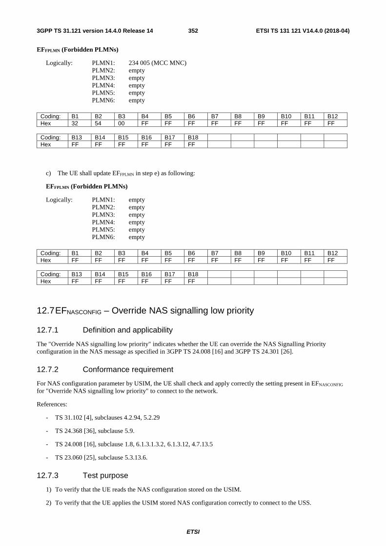
ETSI
ETSI TS 131 121 V14.4.0 (2018-04)3523GPP TS 31.121 version 14.4.0 Release 14
EFFPLMN (Forbidden PLMNs)
Logically: PLMN1: 234 005 (MCC MNC) PLMN2: empty PLMN3: empty PLMN4: empty PLMN5: empty PLMN6: empty
Coding: B1 B2 B3 B4 B5 B6 B7 B8 B9 B10 B11 B12 Hex 32 54 00 FF FF FF FF FF FF FF FF FF Coding: B13 B14 B15 B16 B17 B18 Hex FF FF FF FF FF FF
c) The UE shall update EFFPLMN in step e) as following:
EFFPLMN (Forbidden PLMNs)
Logically: PLMN1: empty PLMN2: empty PLMN3: empty PLMN4: empty PLMN5: empty PLMN6: empty
Coding: B1 B2 B3 B4 B5 B6 B7 B8 B9 B10 B11 B12 Hex FF FF FF FF FF FF FF FF FF FF FF FF Coding: B13 B14 B15 B16 B17 B18 Hex FF FF FF FF FF FF
12.7 EFNASCONFIG – Override NAS signalling low priority
12.7.1 Definition and applicability
The "Override NAS signalling low priority" indicates whether the UE can override the NAS Signalling Priority configuration in the NAS message as specified in 3GPP TS 24.008 [16] and 3GPP TS 24.301 [26].
12.7.2 Conformance requirement
For NAS configuration parameter by USIM, the UE shall check and apply correctly the setting present in EFNASCONFIG for "Override NAS signalling low priority" to connect to the network.
References:
- TS 31.102 [4], subclauses 4.2.94, 5.2.29
- TS 24.368 [36], subclause 5.9.
- TS 24.008 [16], subclause 1.8, 6.1.3.1.3.2, 6.1.3.12, 4.7.13.5
- TS 23.060 [25], subclause 5.3.13.6.
12.7.3 Test purpose
1) To verify that the UE reads the NAS configuration stored on the USIM.
2) To verify that the UE applies the USIM stored NAS configuration correctly to connect to the USS.

ETSI
ETSI TS 131 121 V14.4.0 (2018-04)3533GPP TS 31.121 version 14.4.0 Release 14
12.7.4 Method of test
12.7.4.1 Initial conditions
a) The USS transmits on the BCCH, with the following network parameters: - Attach/detach: disabled.
- LAI (MCC/MNC/LAC): 246/081/0001.
- RAI (MCC/MNC/LAC/RAC): 246/081/0001/05.
- Access control: unrestricted.
b) The default Non Access Stratum Configuration UICC is installed into the Terminal with the following exception: EFNASCONFIG (Non Access Stratum Configuration)
Logically: NAS signalling priority value: NAS signalling low priority NMO I Behaviour value: "NMO I, Network Mode of Operation I" indication is not used Attach with IMSI value: normal behaviour is applied Minimum Periodic Search Timer value: 00 Extended access barring value: extended access barring is applied for the UE Timer T3245 Behaviour value: T3245 not used Override NAS signalling low priority: Indicates that the UE can override the NAS signalling low priority
indicator Override Extended access barring: Indicates that the UE can override extended access barring
Coding: B1 B2 B3 B4 B5 B6 B7 B8 B9 B10 B11 Hex 80 01 01 81 01 00 82 01 00 83 01 Coding: B12 B13 B14 B15 B16 B17 B18 B19 B20 B21 B22 Hex 00 84 01 01 85 01 00 86 01 01 87 Coding: B23 B24 Hex 01 01
12.7.4.2 Procedure
a) The UE is powered on where the UICC is configured as defined in b) in the initial conditions.
b) The user requests activation of a PDP context. After receipt of ACTIVATE PDP CONTEXT REQUEST from the UE, the USS sends ACTIVATE PDP CONTEXT REJECT to the UE indicating:
- SM cause value # 26: insufficient resources;
- Back-off timer T3396: 1 minute
c) Before timer T3396 expires, the users request activation of a PDP context, the UE sends ACTIVATE PDP CONTEXT REQUEST, the USS sends ACTIVATE PDP CONTEXT ACCEPT to the UE.
d) The UE is powered down.
12.7.5 Acceptance criteria
a) After power on in step a) the UE shall read EFNASCONFIG
b) In step b) the UE shall set in ACTIVATE PDP CONTEXT REQUEST message the low priority indicator to "MS is configured for NAS signalling low priority" in the device properties.
c) In step c) the UE shall send ACTIVATE PDP CONTEXT REQUEST message where the low priority indicator is set to "MS is not configured for NAS signalling low priority" in the device properties.
ETSI
ETSI TS 131 121 V14.4.0 (2018-04)3543GPP TS 31.121 version 14.4.0 Release 14
12.8 EFNASCONFIG – Override Extended access barring
12.8.1 Definition and applicability
The "Override Extended Access Barring" indicates whether the UE can override "Extended Access Barring" configured to extended access barring.
The handling of extended access barring for the UE when the Override Extended Access Barring is used is specified in 3GPP TS 24.008 [16] and 3GPP TS 24.301 [26].
12.8.2 Conformance requirement
For NAS configuration parameter by USIM, the UE shall check and apply correctly the setting present in EFNASCONFIG for "Override Extended Access Barring" to connect to the network.
References:
- TS 31.102 [4], subclauses 4.2.94, 5.2.29
- TS 24.368 [36], subclause 5.10.
- TS 23.060 [25], subclause 5.3.13.6.
- TS 23.401 [37], subclause 4.3.17.2, 4.3.17.4
- TS 22.011 [6], subclause 4.3.4.1.
12.8.3 Test purpose
1) To verify that the UE reads the NAS configuration stored on the USIM.
2) To verify that the UE applies the USIM stored NAS configuration correctly to connect to the USS.
3) To verify that the UE overrides "Extended Access Barring" when the Override Extended Access Barring is used
12.8.4 Method of test
12.8.4.1 Initial conditions
a) The USS transmits on the BCCH, with the following network parameters:
- Attach/detach: disabled.
- LAI (MCC/MNC/LAC): 246/081/0001.
- RAI (MCC/MNC/LAC/RAC): 246/081/0001/05.
- Access control: unrestricted.
- SYSTEM INFORMATION BLOCK TYPE 21:
EAB Authorization Mask: 0010000000 (Mobile stations configured for EAB and a member of Access Class 7 are barred)
EAB Subcategory (2 bit): 00 (The EAB Authorization mask is applicable to all mobile stations configured for EAB.)
b) The default Non Access Stratum Configuration UICC is installed into the Terminal with the following exception: EFNASCONFIG (Non Access Stratum Configuration)
Logically: NAS signalling priority value: Reserved (NAS signalling low priority is not used) NMO I Behaviour value: "NMO I, Network Mode of Operation I" indication is not used Attach with IMSI value: normal behaviour is applied Minimum Periodic Search Timer value: 00

ETSI
ETSI TS 131 121 V14.4.0 (2018-04)3553GPP TS 31.121 version 14.4.0 Release 14
Extended access barring value: extended access barring is applied for the UE Timer T3245 Behaviour value: T3245 not used Override NAS signalling low priority: Indicates that the UE can override the NAS signalling low priority
indicator Override Extended access barring: Indicates that the UE can override extended access barring
Coding: B1 B2 B3 B4 B5 B6 B7 B8 B9 B10 B11 Hex 80 01 00 81 01 00 82 01 00 83 01 Coding: B12 B13 B14 B15 B16 B17 B18 B19 B20 B21 B22 Hex 00 84 01 01 85 01 00 86 01 01 87 Coding: B23 B24 Hex 01 01
12.8.4.2 Procedure
a) The UE shall be powered on where the UICC is configured as defined in b) in the initial conditions and the USS transmits of the BCCH as defined inside the initial conditions.
b) User request activate a PDP context. The UE sends ACTIVATE PDP CONTEXT REQUEST, the USS sends ACTIVATE PDP CONTEXT ACCEPT to the UE.
c) The UE is powered down
12.8.5 Acceptance criteria
a) After power on in step a) the UE shall reads EFNASCONFIG
b) In step b) the UE shall send ACTIVATE PDP CONTEXT REQUEST message to the USS.
12.9 EFNASCONFIG – Fast First Higher Priority PLMN Search
12.9.1 Definition and applicability
The "Fast First Higher Priority PLMN Search" indicates whether the UE performs the first search for a higher priority PLMN after at least 2 minutes and at most T minutes upon entering a VPLMN as specified in 3GPP TS 23.122 [31].
12.9.2 Conformance requirement
For NAS configuration parameter by USIM, the UE shall check and apply correctly the setting present in EFNASCONFIG for "Fast First Higher Priority PLMN Search" to connect to the network.
References:
- TS 31.102 [4], subclauses 4.2.94, 5.2.29
- TS 24.368 [36], subclause 5.10a.
- TS 23.122 [31], subclause 4.4.3.3.1
12.9.3 Test purpose
1) To verify that the UE reads the NAS configuration stored on the USIM. 2) To verify that the UE applies the USIM stored NAS configuration correctly to connect to the USS. 3) To verify that the UE performs first search for higher priority PLMN according to "Fast First Higher Priority
PLMN Search" configuration when this parameter is present and used.

ETSI
ETSI TS 131 121 V14.4.0 (2018-04)3563GPP TS 31.121 version 14.4.0 Release 14
12.9.4 Method of test
12.9.4.1 Initial conditions
a) The USS transmits on BCCH, with the following network parameters: - Attach/detach: disabled.
- LAI (MCC/MNC/LAC): 244/009/0001.
- RAI (MCC/MNC/LAC/RAC): 244/009/0001/05
- Access control: unrestricted.
b) After the registration of UE the USS transmits on a second BCCH, with the following network parameters: - Attach/detach: disabled.
- LAI (MCC/MNC/LAC): 244/081/0001.
- RAI (MCC/MNC/LAC/RAC): 244/081/0001/05
- Access control: unrestricted.
c) The default Non Access Stratum Configuration UICC is installed into the Terminal with the following exception:
EFHPPLMN (Higher Priority PLMN Search period)
Logically: set to 6 minutes
Coding: B1 Hex 01
EFNASCONFIG (Non Access Stratum Configuration)
Logically: NAS signalling priority value: Reserved (NAS signalling low priority is not used) NMO I Behaviour value: "NMO I, Network Mode of Operation I" indication is not used Attach with IMSI value: normal behaviour is applied Minimum Periodic Search Timer value: 00 Extended access barring value: extended access barring is not applied for the UE Timer T3245 Behaviour value: T3245 not used Override NAS signalling low priority: Indicates that the UE cannot override the NAS signalling low
priority indicator Override Extended access barring: Indicates that the UE cannot override extended access barring Fast First Higher Priority PLMN Search: Indicates that the Fast First Higher Priority PLMN Search is
enabled EUTRA Disabling Allowed For EMM Cause15: disabled SM_RetryWaitTime: E0 SM_RetryAtRATChange: UE is allowed to retry the corresponding ESM procedure in S1
mode if an SM procedure was rejected in A/Gb or Iu mode, and to retry the corresponding SM procedure in A/Gb or Iu mode if an ESM procedure was rejected in S1 mode.
Coding: B1 B2 B3 B4 B5 B6 B7 B8 B9 B10 B11 Hex 80 01 00 81 01 00 82 01 00 83 01 Coding: B12 B13 B14 B15 B16 B17 B18 B19 B20 B21 B22 Hex 00 84 01 00 85 01 00 86 01 00 87 Coding: B23 B24 B25 B26 B27 B28 B29 B30 B31 B32 B33 Hex 01 00 88 01 01 89 01 00 8A 01 E0 Coding: B34 B35 B36 Hex 8B 01 00
ETSI
ETSI TS 131 121 V14.4.0 (2018-04)3573GPP TS 31.121 version 14.4.0 Release 14
12.9.4.2 Procedure
a) The UE shall be powered on where the UICC is configured as defined in b) in the initial conditions and the USS starts to transmit on the first BCCH with the MMC/MNC 246/009.
b) Depending on which domain the UE is going to be registered on, the UE performs CS, PS or CS/PS registration to the USS.
c) The USS starts to send on the second BCCH with the MCC/MNC 244/081.
d) Depending on which domain the UE is going to be registered on, the UE performs CS, PS or CS/PS registration to the USS on the cell related to the BCCH transmitting MCC/MNC 244/081.
e) The UE is powered down.
12.9.5 Acceptance criteria
a) After power on in step a) the UE shall read EFNASCONFIG
b) The UE shall perform step d) after 2 - 6 minutes.
12.10 EFNASCONFIG – E-UTRA Disabling Allowed for EMM cause #15
12.10.1 Definition and applicability
The "EUTRA Disabling Allowed For EMM Cause #15" indicates whether the UE is allowed to disable the E-UTRA capability when it receives the Extended EMM cause IE with value "E-UTRAN not allowed" as described in 3GPP TS 24.301 [26].
12.10.2 Conformance requirement
For NAS configuration parameter by USIM, the UE shall check and apply the setting present in EFNASCONFIG for "EUTRA Disabling Allowed For EMM Cause #15" to connect to the network.
References:
- TS 31.102 [4], subclauses 4.2.94, 5.2.29
- TS 24.368 [36], subclause 5.10b.
- TS 24.301 [26], subclause 4.5, 5.5.1.2.5
12.10.3 Test purpose
1) To verify that the UE reads the NAS configuration stored on the USIM. 2) To verify that the UE applies the USIM stored NAS configuration correctly to connect to the USS
3) To verify that the UE shall disable the E-UTRA capability and search for a suitable cell in GERAN or UTRAN radio access technology upon ATTACH REJECT reception that include both EMM cause #15 "no suitable cells in tracking area" and an Extended EMM cause IE with value "E-UTRAN not allowed" if " EUTRA Disabling Allowed For EMM Cause #15" is present and enabled in the UE.
12.10.4 Method of test
12.10.4.1 Initial conditions
a) For this test both a UTRAN USS and an E-UTRAN E-USS is needed.
The E-USS transmits on the BCCH, with the following network parameters:
- TAI (MCC/MNC/TAC): 244/003/0001.

ETSI
ETSI TS 131 121 V14.4.0 (2018-04)3583GPP TS 31.121 version 14.4.0 Release 14
- Access control: unrestricted.
At step c) the E-USS transmits on the BCCH, with the following network parameters:
- TAI (MCC/MNC/TAC): 244/003/0002.
- Access control: unrestricted.
At step c) the USS transmits on BCCH, with the following network parameters:
- Attach/detach: disabled.
- LAI (MCC/MNC/LAC): 244/003/0003.
- Access control: unrestricted.
The UICC is installed into the Terminal and the UE is set to automatic PLMN selection mode.
b) The default Non Access Stratum Configuration of E-UTRAN/EPC UICC is installed into the Terminal with the following exception:
EFNASCONFIG (Non Access Stratum Configuration)
Logically: NAS signalling priority value: Reserved (NAS signalling low priority is not used) NMO I Behaviour value: "NMO I, Network Mode of Operation I" indication is not used Attach with IMSI value: normal behaviour is applied Minimum Periodic Search Timer value: 00 Extended access barring value: extended access barring is not applied for the UE Timer T3245 Behaviour value: T3245 not used Override NAS signalling low priority: Indicates that the UE cannot override the NAS signalling low
priority indicator Override Extended access barring: Indicates that the UE cannot override extended access barring Fast First Higher Priority PLMN Search: Indicates that the Fast First Higher Priority PLMN Search is
enabled EUTRA Disabling Allowed For EMM Cause15: enabled SM_RetryWaitTime: E0 SM_RetryAtRATChange: UE is allowed to retry the corresponding ESM procedure in S1
mode if an SM procedure was rejected in A/Gb or Iu mode, and to retry the corresponding SM procedure in A/Gb or Iu mode if an ESM procedure was rejected in S1 mode.
Coding: B1 B2 B3 B4 B5 B6 B7 B8 B9 B10 B11 Hex 80 01 00 81 01 00 82 01 00 83 01 Coding: B12 B13 B14 B15 B16 B17 B18 B19 B20 B21 B22 Hex 00 84 01 00 85 01 00 86 01 00 87 Coding: B23 B24 B25 B26 B27 B28 B29 B30 B31 B32 B33 Hex 01 00 88 01 00 89 01 01 8A 01 E0 Coding: B34 B35 B36 Hex 8B 01 00
12.10.4.2 Procedure
a) The UE shall be powered on where the UICC is configured as defined in b) in the initial conditions and the E-USS starts to send only on the BCCH with the MCC/MNC 244/003.
b) After receipt of AttachRequest from the UE, the E-USS sends Attach Reject message with:
- EMM cause set to #15: "No suitable cells in tracking area",
- Extended EMM cause IE: "E-UTRAN not allowed"
c) The E-USS starts to send on the BCCH with MCC/MNC 244/003 and the USS starts to send on the BCCH with MCC/MNC 244/003.

ETSI
ETSI TS 131 121 V14.4.0 (2018-04)3593GPP TS 31.121 version 14.4.0 Release 14
d) After receipt of an RRCConnectionRequest from the UE, the USS sends RRCConnectionSetup to the UE, followed by RRCConnectionSetupComplete sent by the UE to the USS.
e) The UE is powered down.
12.10.5 Acceptance criteria
a) After power on in step a) the UE shall read EFNASCONFIG
b) In step d) the UE shall send a RRCConnectionRequest on the UTRAN-cell related to the BCCH transmitting MCC/MNC 244/003 to the USS.
12.11 EFNASCONFIG – SM_RetryWaitTime
12.11.1 Definition and applicability
The "SM_RetryWaitTime" indicates a configured UE retry wait time value applicable when in HPLMN or EHPLMN (see 3GPP TS 23.122 [31]) for controlling the UE session management retry behaviour when prior session management request was rejected by the network with cause value #8, #27, #32, #33 as specified in 3GPP TS 24.008 [16] and 3GPP TS 24.301 [26].
SM_RetryWaitTime shall be coded in the same format as the value part of GPRS Timer 3 IE as specified in Table 10.5.163a/3GPP TS 24.008 [16] converted into a decimal value.
12.11.2 Conformance requirement
For NAS configuration parameter by USIM, the UE shall check and apply the setting present in EFNASCONFIG for "SM_RetryWaitTime" to connect to the network.
Reference:
- TS 31.102 [4], subclauses 4.2.94, 5.2.29
- TS 24.368 [36], subclause 5.10c.
- TS 24.008 [16], subclauses 6.1.3.1.3.3, 10.5.7.4a.
12.11.3 Test purpose
1) To verify that the UE reads the NAS configuration stored on the USIM. 2) To verify that the UE applies the USIM stored NAS configuration correctly to connect to the USS.
3) To verify that the UE behaves as described in TS 24.008 [16] subclause 6.1.3.1.3.3, using the default value of 12 minutes for the back-off timer when the SM Retry Timer value is not configured.
4) To verify that the UE behaves as described in TS 24.008 [16] subclause 6.1.3.1.3.3, using the configured SM Retry Timer value as back-off timer value.
12.11.4 Method of test
12.11.4.1 Initial conditions
a) The USS transmits on BCCH, with the following network parameters:
- Attach/detach: disabled.
- LAI (MCC/MNC/LAC): 246/081/0001.
- RAI (MCC/MNC/LAC/RAC): 246/081/0001/05.
- Access control: unrestricted.

ETSI
ETSI TS 131 121 V14.4.0 (2018-04)3603GPP TS 31.121 version 14.4.0 Release 14
b) The default Non Access Stratum Configuration UICC is installed into the Terminal with the following exception: EFNASCONFIG (Non Access Stratum Configuration)
Logically: NAS signalling priority value: Reserved (NAS signalling low priority is not used) NMO I Behaviour value: "NMO I, Network Mode of Operation I" indication is not used Attach with IMSI value: normal behaviour is applied Minimum Periodic Search Timer value: 00 Extended access barring value: extended access barring is not applied for the UE Timer T3245 Behaviour value: T3245 not used Override NAS signalling low priority: Indicates that the UE cannot override the NAS signalling low
priority indicator Override Extended access barring: Indicates that the UE cannot override extended access barring Fast First Higher Priority PLMN Search: Indicates that the Fast First Higher Priority PLMN Search is not
enabled EUTRA Disabling Allowed For EMM Cause15: disabled SM_RetryWaitTime: 60 seconds SM_RetryAtRATChange: UE is allowed to retry the corresponding ESM procedure in S1
mode if an SM procedure was rejected in A/Gb or Iu mode, and to retry the corresponding SM procedure in A/Gb or Iu mode if an ESM procedure was rejected in S1 mode.
Coding: B1 B2 B3 B4 B5 B6 B7 B8 B9 B10 B11 Hex 80 01 00 81 01 00 82 01 00 83 01 Coding: B12 B13 B14 B15 B16 B17 B18 B19 B20 B21 B22 Hex 00 84 01 00 85 01 00 86 01 00 87 Coding: B23 B24 B25 B26 B27 B28 B29 B30 B31 B32 B33 Hex 01 00 88 01 00 89 01 00 8A 01 7E Coding: B34 B35 B36 Hex 8B 01 00
12.11.4.2 Procedure
a) The UE is powered on where the UICC is configured as defined in b) in the initial conditions.
b) User request activate a PDP context. After receipt of ACTIVATE PDP CONTEXT REQUEST from the UE, the USS sends ACTIVATE PDP CONTEXT REJECT to the UE indicating:
- SM cause value #8: operator determined barring;
c) User request activate a PDP context and the UE sends ACTIVATE PDP CONTEXT REQUEST, the USS sends ACTIVATE PDP CONTEXT ACCEPT to the UE.
d) The UE is powered down.
12.11.5 Acceptance criteria
a) After power on in step a) the UE shall read EFNASCONFIG
b) In step c) the UE shall send ACTIVATE PDP CONTEXT REQUEST message after the SM_RetryWaitTime of 1 minute has expired.
12.12 EFNASCONFIG – SM_RetryAtRATChange
12.12.1 Definition and applicability
The "SM_RetryAtRATChange" indicates the UE's retry behaviour when in HPLMN or EHPLMN (see 3GPP TS 23.122 [31]) after inter-system change between S1 mode and A/Gb or Iu mode as specified in 3GPP TS 24.008 [16] and 3GPP TS 24.301 [26].

ETSI
ETSI TS 131 121 V14.4.0 (2018-04)3613GPP TS 31.121 version 14.4.0 Release 14
12.12.2 Conformance requirement
Editor's note: this clause is for future study.
12.12.3 Test purpose
Editor's note: this clause is for future study.
12.12.4 Method of test
Editor's note: this clause is for future study.
12.12.5 Acceptance criteria
Editor's note: this clause is for future study.
13 UICC interface during PSM
13.1 UICC interface in PSM handling for E-UTRAN – No UICC deactivation in PSM
13.1.1 Definition and applicability
PSM is intended for UEs that are expecting only infrequent mobile originating and terminating services and that can accept a corresponding latency in the mobile terminating communication. In order to reduce power consumption while in PSM, and only in case the PIN of the USIM is disabled, the ME may optionally deactivate the UICC after entering the PSM.
13.1.2 Conformance requirement
In order to reduce power consumption while the ME is in PSM, and only in case the PIN of the USIM is disabled, the ME may optionally deactivate the UICC (as specified in clause 6A.1 of 3GPP TS 31.101 [39]) after entering the PSM.
Reference:
- TS 31.102 [4], subclause 5.1.10;
- TS 24.301 [26], subclauses 5.3.5 and 5.3.11.
- TS 31.101 [39], clause 6A.1.
13.1.3 Test purpose
1) To verify that UE does not deactivate the UICC in case the PIN for the USIM is enabled and verified.
13.1.4 Method of test
13.1.4.1 Initial conditions
The UE is configured to use Power Saving Mode.
The UE is configured to use the timer T3324 set to T3324_V.

ETSI
ETSI TS 131 121 V14.4.0 (2018-04)3623GPP TS 31.121 version 14.4.0 Release 14
The E-USS transmits on the BCCH, with the following network parameters:
- TAI (MCC/MNC/TAC): 246/081/0001.
- Access control: unrestricted.
The NB-SS transmits on the BCCH, with the following network parameters:
- TAI (MCC/MNC/TAC): 246/081/0001.
- Access control: unrestricted.
The default E-UTRAN UICC is used with the following exceptions:
EFUMPC (UICC Maximum Power Consumption)
Byte: B1 B2 B3 Coding: 3C 05 00
The PIN of the USIM is enabled and verified
13.1.4.2 Procedure
a) The UE is switched on.
b) The UE requests RRC Connection and transmits an ATTACH REQUEST message to the E-USS/NB-SS including T3324 set to T3324_V.
c) The E-USS/NB-SS sends the ATTACH ACCEPT message contains T3324 set to T3324_V and T3412 set to T3412_V.. It shall not contain the eDRX parameters
d) After receipt of the AttachComplete during registration from the UE, the E-USS/NB-SS sends RRCConnectionRelease/RRCConnectionRelease-NB, to the UE.
e) After the T3412 timer expires the UE sends TRACKING AREA UPDATE REQUEST
f) The E-USS/NB-SS sends TRACKING AREA UPDATE ACCEPT.
g) The UE is switched off.
13.1.5 Acceptance criteria
1) After step c) the UE shall not deactivate the UICC or send SUSPEND UICC command.
13.2 UICC interface in PSM handling for E-UTRAN – PSM not accepted by E-USS/NB-SS
13.2.1 Definition and applicability
PSM is intended for UEs that are expecting only infrequent mobile originating and terminating services and that can accept a corresponding latency in the mobile terminating communication. In order to reduce power consumption while in PSM, and only in case the PIN of the USIM is disabled, the ME may optionally deactivate the UICC after entering the PSM.
13.2.2 Conformance requirement
In order to reduce power consumption while the ME is in PSM, and only in case the PIN of the USIM is disabled, the ME may optionally deactivate the UICC (as specified in clause 6A.1 of 3GPP TS 31.101 [39]) after entering the PSM.
Reference:

ETSI
ETSI TS 131 121 V14.4.0 (2018-04)3633GPP TS 31.121 version 14.4.0 Release 14
- TS 31.102 [4], subclause 5.1.10;
- TS 24.301 [26], subclauses 5.3.5 and 5.3.11.
- TS 31.101 [39] in clause 6A.1.
13.2.3 Test purpose
1) To verify that UE does not deactivate the UICC in case the network is not supporting/accepting PSM.
13.2.4 Method of test
13.2.4.1 Initial conditions
The UE is configured to use Power Saving Mode.
The UE is configured to use the timer T3324 set to T3324_V.
The E-USS transmits on the BCCH, with the following network parameters:
- TAI (MCC/MNC/TAC): 246/081/0001.
- Access control: unrestricted.
The NB-SS transmits on the BCCH, with the following network parameters:
- TAI (MCC/MNC/TAC): 246/081/0001.
- Access control: unrestricted.
The default E-UTRAN UICC is installed into the Terminal.
The PIN of the USIM is disabled.
13.2.4.2 Procedure
a) The UE is switched on.
b) The UE requests RRC Connection and transmits an ATTACH REQUEST message to the E-USS/NB-SS including T3324 set to T3324_V.
c) The E-USS/NB-SS sends the ATTACH ACCEPT message contains a T3324 set to “deactivated”. It shall not contain the eDRX parameters.
d) After receipt of the AttachComplete during registration from the UE, the E-USS/NB-SS sends RRCConnectionRelease/RRCConnectionRelease-NB, to the UE
e) After the time period T3324_V2 has passed, the E-USS/NB-SS transmits Paging/Paging-NB to the UE using the S-TMSI.
f) After receipt of RRCConnectionRequest/RRCConnectionRequest-NB message from the UE, the E-USS/NB-SS sends RRCConnectionSetup/RRCConnectionSetup-NB message to the UE, followed by RRCConnectionSetupComplete/RRCConnectionSetupComplete-NB sent by the UE to the E-USS/NB-SS.
g) The terminal sends EMM Service Request followed by the activation of AS security and the Dedicated EPS bearer.
h) The E-USS/NB-SS sends SERVICE ACCEPT followed by RRCConnectionRelease/RRCConnectionRelease-NB to the UE.
i) The UE is switched off.

ETSI
ETSI TS 131 121 V14.4.0 (2018-04)3643GPP TS 31.121 version 14.4.0 Release 14
13.2.5 Acceptance criteria
1) After step c) the UE shall not deactivate the UICC.
13.3 UICC interface in PSM handling for E-UTRAN – UICC deactivation in PSM
13.3.1 Definition and applicability
PSM is intended for UEs that are expecting only infrequent mobile originating and terminating services and that can accept a corresponding latency in the mobile terminating communication. In order to reduce power consumption while in PSM, and only in case the PIN of the USIM is disabled, the ME may optionally deactivate the UICC after entering the PSM.
13.3.2 Conformance requirement
In order to reduce power consumption while the ME is in PSM, and only in case the PIN of the USIM is disabled, the ME may optionally deactivate the UICC (as specified in clause 6A.1 of 3GPP TS 31.101 [39]) after entering the PSM.
In this case, the ME shall perform these steps before it can leave the PSM:
- re-activate the UICC (as specified in clause 6A.1 of 3GPP TS 31.101 [39]),
- re-initialize the USIM (as specified in clause 5.1.1 [4]), with the exception of re-reading EFs that are not required for the verification of the USIM,
- take appropriate steps to verify that the same USIM is used.
Verification shall include at least the check of the content of the following EFs: EFICCID, EFIMSI, EFLOCI, EFPSLOCI and EFEPSLOCI.
Reference:
- TS 31.102 [4], subclause 5.1.10;
- TS 24.301 [26], subclauses 5.3.5 and 5.3.11.
- TS 31.101 [39] in clause 6A.1.
13.3.3 Test purpose
1) To verify that when the UE enters PSM it deactivates the UICC in case the PIN for the USIM is disabled.
2) To verify that UE when it leaves the PSM performs the following steps:
- re-activates the UICC;
- re-initializes the USIM;
- verifies the following EFs: EFICCID, EFIMSI, EFLOCI and EFEPSLOCI.
13.3.4 Method of test
13.3.4.1 Initial conditions
The UE is configured to use Power Saving Mode.
The UE is configured to use the timer T3324 set to T3324_V.
The E-USS transmits on the BCCH, with the following network parameters:

ETSI
ETSI TS 131 121 V14.4.0 (2018-04)3653GPP TS 31.121 version 14.4.0 Release 14
- TAI (MCC/MNC/TAC): 246/081/0001.
- Access control: unrestricted.
The NB-SS transmits on the BCCH, with the following network parameters:
- TAI (MCC/MNC/TAC): 246/081/0001.
- Access control: unrestricted.
The default E-UTRAN UICC is installed into the Terminal.
The PIN of the USIM is disabled.
13.3.4.2 Procedure
a) The UE is switched on.
b) The UE requests RRC Connection and transmits an ATTACH REQUEST message to the E-USS/NB-SS including T3324 set to T3324_V.
c) The E-USS/NB-SS sends the ATTACH ACCEPT message contains T3324 set to T3324_V and T3412 set to T3412_V. It shall not contain the eDRX parameters.
d) After receipt of the AttachComplete during registration from the UE, the E-USS/NB-SS sends RRCConnectionRelease/RRCConnectionRelease-NB, to the UE.
e) After the T3412 timer expires the UE sends TRACKING AREA UPDATE REQUEST.
f) The E-USS/NB-SS sends TRACKING AREA UPDATE ACCEPT.
g) The UE is switched off.
13.3.5 Acceptance criteria
1) After step d) and the expiration of T3324 timer, the UE deactivates the UICC.
2) After step e) the UE leaves the PSM and re-activates the UICC, re-initializes the USIM and verifies the following EFs: EFICCID, EFIMSI, EFLOCI and EFEPSLOCI.
13.4 UICC interface in PSM for E-UTRAN – SUSPEND UICC
13.4.1 Definition and applicability
PSM is intended for UEs that are expecting only infrequent mobile originating and terminating services and that can accept a corresponding latency in the mobile terminating communication. If the UICC supports the UICC suspension mechanism (SUSPEND UICC command), the ME may suspend the UICC after entering the PSM. In this case, the ME shall successfully resume the UICC before it can leave the PSM.
13.4.2 Conformance requirement
If the UICC supports the UICC suspension mechanism (SUSPEND UICC command), the ME may suspend the UICC after entering the PSM. In this case, the ME shall successfully resume the UICC before it can leave the PSM.
Reference:
- TS 31.102 [4], subclause 5.1.10;
- TS 24.301 [26], subclauses 5.3.5, 5.3.11 and 5.5.1.2.2.
- TS 31.101 [39] in clause 11.1.22.
ETSI
ETSI TS 131 121 V14.4.0 (2018-04)3663GPP TS 31.121 version 14.4.0 Release 14
13.4.3 Test purpose
1) To verify that UE does not send SUSPEND UICC command to the UICC in case the UICC does not indicates the support of SUSPEND UICC command in EFUMPC
2) To verify that UE sends SUSPEND UICC command to the UICC in case the UICC indicates the support of SUSPEND UICC command in EFUMPC after entering the PSM
3) To verify that UE resumes the UICC before it can leave the PSM.
13.4.4 Method of test
13.4.4.1 Initial conditions
The UE is configured to use Power Saving Mode.
The UE is configured to use the timer T3324 set to T3324_V.
The E-USS transmits on the BCCH, with the following network parameters:
- TAI (MCC/MNC/TAC): 246/081/0001.
- Access control: unrestricted.
The NB-SS transmits on the BCCH, with the following network parameters:
- TAI (MCC/MNC/TAC): 246/081/0001.
- Access control: unrestricted.
The default E-UTRAN UICC is used with the following exceptions:
EFUMPC (UICC Maximum Power Consumption)
Byte: B1 B2 B3 Coding: 3C 05 02
The PIN of the USIM is enabled and verified.
13.4.4.2 Procedure
a) The UE is switched on.
b) The UE requests RRC Connection and transmits an ATTACH REQUEST message to the E-USS/NB-SS including T3324 set to T3324_V.
c) The E-USS/NB-SS sends the ATTACH ACCEPT message contains T3324 set to T3324_V and T3412 set to T3412_V. It shall not contain the eDRX parameters.
d) The UE sends SUSPEND UICC command to the UICC indicating “Minimum duration of the suspension proposed by the terminal” and the “Maximum duration of the suspension proposed by the terminal”. e) The UICC returns Maximum duration of the “suspension negotiated by the UICC” = “Minimum duration of the suspension proposed by the terminal”, Resume token and SW 9000.
f) After the T3412 timer expires the UE sends TRACKING AREA UPDATE REQUEST
g) The E-USS/NB-SS sends TRACKING AREA UPDATE ACCEPT.
h) The UE is switched off.
13.4.5 Acceptance criteria
1) After step d) the UE deactivates the UICC as specified in 3GPP TS 31.101 [39].
ETSI
ETSI TS 131 121 V14.4.0 (2018-04)3673GPP TS 31.121 version 14.4.0 Release 14
2) After step f) the UE leaves the PSM and resumes the UICC.
14 UICC interface during eDRX
14.1 UICC interface during eDRX for E-UTRAN – eDRX is not supported by the UICC
14.1.1 Definition and applicability
In order to reduce power consumption when the UE uses extended idle mode DRX cycle, the UE may optionally deactivate the UICC during the extended idle mode DRX cycle.
14.1.2 Conformance requirement
In case the UICC does not support the UICC suspension mechanism, the PIN of the USIM is disabled and deactivation of UICC is authorized in EFAD, the UE may optionally deactivate the UICC (as specified in clause 6A.1 of 3GPP TS 31.101 [39]) during the extended idle mode DRX cycle.
Reference:
- TS 31.102 [4], subclause 5.1.11;
- TS 24.301 [26], subclauses 5.3.12.
- TS 23.401 [37], subclause 5.13a.
- TS 31.101 [39] in clause 6A.1.
14.1.3 Test purpose
1) To verify that UE does not deactivate the UICC in case the ME is not authorized to modify the polling interval and/or disable the UICC interface during extended DRX cycle in EFAD in USIM.
14.1.4 Method of test
14.1.4.1 Initial conditions
The UE is configured to request the use of eDRX (in the ATTACH REQUEST and TRACKING AREA UPDATE messages).
The E-USS transmits on the BCCH, with the following network parameters:
- TAI (MCC/MNC/TAC): 246/081/0001.
- Access control: unrestricted.
The NB-SS transmits on the BCCH, with the following network parameters:
- TAI (MCC/MNC/TAC): 246/081/0001.
- Access control: unrestricted.
The default E-UTRAN UICC is used with the following exceptions:
EFUMPC (UICC Maximum Power Consumption)
Byte: B1 B2 B3 Coding: 3C 05 00

ETSI
ETSI TS 131 121 V14.4.0 (2018-04)3683GPP TS 31.121 version 14.4.0 Release 14
The PIN of the USIM is enabled and verified.
14.1.4.2 Procedure
a) The UE is switched on.
b) The UE requests RRC Connection and transmits an ATTACH REQUEST message to the E-USS/NB-SS including eDRX parameters.
c) The E-USS/NB-SS sends the ATTACH ACCEPT message containing eDRX set to eDRX_V and PTW set to PTW_V. If ATTACH REQUEST in step b) above also contains T3324, the ATTACH ACCEPT message shall contain T3324 set to "deactivated". If ATTACH REQUEST in step b) does not contain T3324, the ATTACH ACCEPT message shall not contain T3324.
d) The E-USS/NB-SS transmits Paging/Paging-NB to the UE using the S-TMSI in a valid paging occasion within the PTW of the paging Hyperframes as per Idle eDRX.
e) After receipt of RRCConnectionRequest/RRCConnectionRequest-NB message from the UE, the E-USS/NB-SS sends RRCConnectionSetup/RRCConnectionSetup-NB message to the UE, followed by RRCConnectionSetupComplete/RRCConnectionSetupComplete-NB sent by the UE to the E-USS/NB-SS.
f) The terminal sends EMM Service Request followed by the activation of AS security and the Dedicated EPS bearer.
j) The E-USS/NB-SS sends SERVICE ACCEPT followed by RRCConnectionRelease/RRCConnectionRelease-NB to the UE.
h) The UE is switched off.
14.1.5 Acceptance criteria
1) After step c) the UE shall not deactivate the UICC or send SUSPEND UICC command.
14.2 UICC interface during eDRX for E-UTRAN – eDRX is not accepted by E-USS/NB-SS
14.2.1 Definition and applicability
In order to reduce power consumption when the UE uses extended idle mode DRX cycle, the UE may optionally deactivate the UICC during the extended idle mode DRX cycle.
14.2.2 Conformance requirement
In case the UICC does not support the UICC suspension mechanism, the PIN of the USIM is disabled and deactivation of UICC is authorized in EFAD, the UE may optionally deactivate the UICC (as specified in clause 6A.1 of 3GPP TS 31.101 [39]) during the extended idle mode DRX cycle.
Reference:
- 3GPP TS 31.102 [4], subclause 5.1.11;
- TS 24.301 [26], subclauses 5.3.12.
- TS 23.401 [37], subclause 5.13a
- 3GPP TS 31.101 [39] in clause 6A.1.

ETSI
ETSI TS 131 121 V14.4.0 (2018-04)3693GPP TS 31.121 version 14.4.0 Release 14
14.2.3 Test purpose
1) To verify that UE does not deactivate the UICC in case extended DRX cycle is not supported by the network.
14.2.4 Method of test
14.2.4.1 Initial conditions
The UE is configured to request the use of eDRX (in the ATTACH REQUEST and TRACKING AREA UPDATE messages).
The E-USS transmits on the BCCH, with the following network parameters:
- TAI (MCC/MNC/TAC): 246/081/0001.
- Access control: unrestricted.
The NB-SS transmits on the BCCH, with the following network parameters:
- TAI (MCC/MNC/TAC): 246/081/0001.
- Access control: unrestricted.
The default E-UTRAN UICC is installed into the Terminal with following exception:
EFAD (Administrative Data)
Logically: the ME is authorized to modify the polling interval and/or disable the UICC interface during extended DRX cycle.
Byte: B1 B2 B3 Coding: 00 00 08
The PIN of the USIM is disabled.
14.2.4.2 Procedure
14.2.4.2 Procedure
a) The UE is switched on.
b) The UE requests RRC Connection and transmits an ATTACH REQUEST message to the E-USS/NB-SS including eDRX parameters:
c) The E-USS/NB-SS sends the ATTACH ACCEPT message where the eDRX parameters are not present. If ATTACH REQUEST in step b) above also contains T3324, the ATTACH ACCEPT message shall contain T3324 set to "deactivated". If ATTACH REQUEST in step b) does not contain T3324, the ATTACH ACCEPT message shall not contain T3324.
d) E-USS/NB-SS transmits Paging/Paging-NB to the UE in a valid paging occasion as per normal DRX
e) After receipt of RRCConnectionRequest/RRCConnectionRequest-NB message from the UE, the E-USS/NB-SS sends RRCConnectionSetup/RRCConnectionSetup-NB message to the UE, followed by RRCConnectionSetupComplete/RRCConnectionSetupComplete-NB sent by the UE to the E-USS/NB-SS.
f) The terminal sends EMM Service Request followed by the activation of AS security and the Dedicated EPS bearer.
j) The E-USS/NB-SS sends SERVICE ACCEPT followed by RRCConnectionRelease/RRCConnectionRelease-NB to the UE.
h) The UE is switched off.

ETSI
ETSI TS 131 121 V14.4.0 (2018-04)3703GPP TS 31.121 version 14.4.0 Release 14
14.2.5 Acceptance criteria
1) After step c) the UE shall not deactivate the UICC.
14.3 UICC interface during eDRX for E-UTRAN – UICC deactivation during eDRX
14.3.1 Definition and applicability
In order to reduce power consumption when the UE uses extended idle mode DRX cycle, the UE may optionally deactivate the UICC during the extended idle mode DRX cycle.
In this case, the UE shall re-activate the UICC, re-initialize the USIM and take appropriate steps to verify that the same USIM is used, before the end of the extended idle mode DRX cycle or before any other transmission to the network
14.3.2 Conformance requirement
In case the UICC does not support the UICC suspension mechanism, the PIN of the USIM is disabled and deactivation of UICC is authorized in EFAD, the UE may optionally deactivate the UICC (as specified in clause 6A.1 of 3GPP TS 31.101 [39]) during the extended idle mode DRX cycle.
In this case, the UE shall re-activate the UICC (as specified in clause 6A.1 of 3GPP TS 31.101 [39]), re-initialize the USIM (as specified in clause 5.1.1 from [4]) and take appropriate steps to verify that the same USIM is used, before the end of the extended idle mode DRX cycle or before any other transmission to the network.
Verification shall include at least the check of the content of the following EFs: EFICCID, EFIMSI, EFLOCI, EFPSLOCI and EFEPSLOCI.
Reference:
- 3GPP TS 31.102 [4], subclause 5.1.11;
- TS 24.301 [26], subclauses 5.3.12.
- TS 23.401 [37], subclause 5.13a
- 3GPP TS 31.101 [39] in clause 6A.1.
14.3.3 Test purpose
1) To verify that UE does not deactivate the UICC in case the ME is not authorized to modify the polling interval and/or disable the UICC interface during extended DRX cycle in EFAD in USIM.
2) To verifies that UE when it leaves the PSM performs the following steps:
- re-activates the UICC.
- re-initializes the USIM
- verifies the following EFs: EFICCID, EFIMSI, EFLOCI and EFEPSLOCI.
14.3.4 Method of test
14.3.4.1 Initial conditions
The UE is configured to request the use of eDRX (in the ATTACH REQUEST and TRACKING AREA UPDATE messages).
The E-USS transmits on the BCCH, with the following network parameters:

ETSI
ETSI TS 131 121 V14.4.0 (2018-04)3713GPP TS 31.121 version 14.4.0 Release 14
- TAI (MCC/MNC/TAC): 246/081/0001.
- Access control: unrestricted.
The NB-SS transmits on the BCCH, with the following network parameters:
- TAI (MCC/MNC/TAC): 246/081/0001.
- Access control: unrestricted.
The default E-UTRAN UICC is installed into the Terminal with following exception:
EFAD (Administrative Data)
Logically: the ME is authorized to modify the polling interval and/or disable the UICC interface during extended DRX cycle.
Byte: B1 B2 B3 Coding: 00 00 08
The PIN of the USIM is disabled.
14.3.4.2 Procedure
a) The UE is switched on.
b) The UE requests RRC Connection and transmits an ATTACH REQUEST message to the E-USS/NB-SS including eDRX parameters:
c) The E-USS/NB-SS sends the ATTACH ACCEPT message containing eDRX set to eDRX_V and PTW set to PTW_V. If ATTACH REQUEST in step b) above also contains T3324, the ATTACH ACCEPT message shall contain T3324 set to "deactivated". If ATTACH REQUEST in step b) does not contain T3324, the ATTACH ACCEPT message shall not contain T3324.
d) The E-USS/NB-SS transmits Paging/Paging-NB to the UE using the S-TMSI in a valid paging occasion within the PTW of the paging Hyperframes as per Idle eDRX.
e) After receipt of a RRCConnectionRequest/RRCConnectionRequest-NB message from the UE, the E-USS/NB-SS sends RRCConnectionSetup/RRCConnectionSetup-NB message to the UE, followed by RRCConnectionSetupComplete/RRCConnectionSetupComplete-NB sent by the UE to the E-USS/NB-SS.
f) The terminal sends EMM Service Request followed by the activation of AS security and the Dedicated EPS bearer.
j) The E-USS/NB-SS sends SERVICE ACCEPT followed by RRCConnectionRelease/RRCConnectionRelease-NB to the UE.
h) The UE is switched off.
14.3.5 Acceptance criteria
1) After step c) the UE the UE deactivates the UICC.
2) After step d) the UE shall re-activate the UICC, re-initialize the USIM and verify the following EFs: EFICCID, EFIMSI, EFLOCI and EFEPSLOCI

ETSI
ETSI TS 131 121 V14.4.0 (2018-04)3723GPP TS 31.121 version 14.4.0 Release 14
14.4 UICC interface during eDRX for E-UTRAN– SUSPEND UICC
14.4.1 Definition and applicability
In order to reduce power consumption when the UE uses extended idle mode DRX cycle, as defined in 3GPP TS 24.301 [26], in case the UICC supports the UICC suspension mechanism (SUSPEND UICC command), the ME may suspend the UICC during the extended idle mode DRX cycle. In this case, the ME shall resume the UICC successfully before the end of the extended idle mode DRX cycle or before any other transmission to the network.
14.4.2 Conformance requirement
In case the UICC supports the UICC suspension mechanism (SUSPEND UICC command), the ME may suspend the UICC during the extended idle mode DRX cycle. In this case, the ME shall resume the UICC successfully before the end of the extended idle mode DRX cycle or before any other transmission to the network.
Reference:
- 3GPP TS 31.102 [4], subclause 5.1.11;
- TS 24.301 [26], subclauses 5.3.12.
- TS 23.401 [37], subclause 5.13a.
- 3GPP TS 31.101 [39] in subclauses 6A.1 and 11.1.22.
14.4.3 Test purpose
1) To verify that UE does not send SUSPEND UICC command to the UICC in case the UICC does not indicates the support of SUSPEND UICC command in EFUMPC during the extended idle mode DRX cycle
2) To verify that UE sends SUSPEND UICC command to the UICC in case the UICC indicates the support of SUSPEND UICC command in EFUMPC during the extended idle mode DRX cycle.
3) To verify that UE resumes the UICC before the end of the extended idle mode DRX cycle or before any other transmission to the network.
14.4.4 Method of test
14.4.4.1 Initial conditions
The UE is configured to request the use of eDRX (in the ATTACH REQUEST and TRACKING AREA UPDATE messages).
The E-USS transmits on the BCCH, with the following network parameters:
- TAI (MCC/MNC/TAC): 246/081/0001.
- Access control: unrestricted.
The NB-SS transmits on the BCCH, with the following network parameters:
- TAI (MCC/MNC/TAC): 246/081/0001.
- Access control: unrestricted.
The default E-UTRAN UICC is used with the following exceptions:
EFUMPC (UICC Maximum Power Consumption)
Byte: B1 B2 B3

ETSI
ETSI TS 131 121 V14.4.0 (2018-04)3733GPP TS 31.121 version 14.4.0 Release 14
Coding: 3C 05 02
EFAD (Administrative Data)
Logically: the ME is authorized to modify the polling interval and/or disable the UICC interface during extended DRX cycle.
Byte: B1 B2 B3 Coding: 00 00 08
The PIN of the USIM is enabled and verified.
14.4.4.2 Procedure
a) The UE is switched on.
b) The UE requests RRC Connection and transmits an ATTACH REQUEST message to the E-USS/NB-SS including eDRX parameters:
c) The E-USS/NB-SS sends the ATTACH ACCEPT message containing eDRX set to eDRX_V and PTW set to PTW_V. If ATTACH REQUEST in step b) above also contains T3324, the ATTACH ACCEPT message shall contain T3324 set to "deactivated". If ATTACH REQUEST in step b) does not contain T3324, the ATTACH ACCEPT message shall not contain T3324.
d)The UE sends SUSPEND UICC command to the UICC indicating "Minimum duration of the suspension proposed by the terminal” and the “Maximum duration of the suspension proposed by the terminal".
e) The UICC returns Maximum duration of the "suspension negotiated by the UICC" = "Minimum duration of the suspension proposed by the terminal", Resume token and SW 9000.
f) The E-USS/NB-SS transmits Paging/Paging-NB to the UE using the S-TMSI in a valid paging occasion within the PTW of the paging Hyperframes as per Idle eDRX.
g) After receipt of RRCConnectionRequest/RRCConnectionRequest-NB message from the UE, the E-USS/NB-SS sends RRCConnectionSetup/RRCConnectionSetup-NB message to the UE, followed by RRCConnectionSetupComplete/RRCConnectionSetupComplete-NB sent by the UE to the E-USS/NB-SS.
h) The terminal sends EMM Service Request followed by the activation of AS security and the Dedicated EPS bearer.
i) The E-USS/NB-SS sends SERVICE ACCEPT followed by RRCConnectionRelease/RRCConnectionRelease-NB to the UE.
j) The UE is switched off.
14.4.5 Acceptance criteria
1) After step e) the UE deactivates the UICC as specified in 3GPP TS 31.101 [39].
2) After step f) the UE resumes the UICC.

ETSI
ETSI TS 131 121 V14.4.0 (2018-04)3743GPP TS 31.121 version 14.4.0 Release 14
Annex A (informative): Change history

ETSI
ETSI TS 131 121 V14.4.0 (2018-04)3753GPP TS 31.121 version 14.4.0 Release 14
TSG # TSG TD# WG TD# CR Rev
Cat Subject/Comment Old New
CT-28 CP-050139 C6-050394 068 - B Introduction of BCD number/ SSC content extension tests
- 6.0.0
CT-28 CP-050139 C6-050396 072 - B Introduction of ACL tests - 6.0.0 CT-28 CP-050139 C6-050436 073 - B Introduction of SDN tests - 6.0.0 CT-28 CP-050139 C6-050452 074 - B Introduction of phonebook selection/ local phonebook
handling test - 6.0.0
CT-29 CP-050325 C6-050658 080 - A Incorrect PUK2 value used in TC 6.1.6 6.0.0 6.1.0 CT-29 CP-050325 C6-050711 088 - A Incorrect value used for EF SMS in TC 8.2.2 6.0.0 6.1.0 CT-29 CP-050331 C6-050654 076 - A Incorrect MCC value used in TC 7.4.1 6.0.0 6.1.0 CT-29 CP-050336 C6-050706 083 - F Clarification of BCD number/ SSC content extension
tests 6.0.0 6.1.0
CT-29 CP-050336 C6-050700 081 - F Numbering and minor corrections 6.0.0 6.1.0 CT-30 CP-050494 C6-050853 090 - F CR to create combined R99 – Rel-6 version 6.1.0 6.2.0 CT-31 CP-060020 C6-060178 095 - F Essential correction of TC 7.2.1 6.2.0 6.3.0 CT-31 - - - - - Update of Change History by TB Officer 6.3.0 6.3.1 CT-32 CP-060285 C6-060224 0096 - F Essential correction of acceptance criteria in 6.1.3.5 and
6.1.4.5 6.3.1 6.4.0
CT-32 CP-060286 C6-060231 0097 - F Essential corrections on ACL TC 9.1.1 6.3.1 6.4.0 CT-33 CP-060507 C6-060517 0098 1 F Essential corrections on Applicability table 6.4.0 6.5.0 CT-34 CP-060543 C6-060792 0099 1 F Essential corrections to 8.1.2 6.5.0 6.6.0 CT-34 CP-060543 C6-060793 0100 1 F Essential correction of EF PLMNwACT coding 6.5.0 6.6.0 CT-35 CP-070064 C6-070098 0101 1 F Essential correction of UICC presence detection test 6.6.0 6.7.0 CT-36 - - - - - Update to Rel-7 version (MCC) 6.7.0 7.0.0 CT-37 CP-070617 C6-070368 0103 - F Essential correction of Location Area Information
parameter in test 7.3 7.0.0 7.1.0
CT-37 CP-070617 C6-070369 0104 - F Essential correction of the applicability of tests 6.4.2, 6.4.3, 6.4.4
7.0.0 7.1.0
CT-38 CP-070846 C6-070526 0105 - F Essential correction on test case 7.1.2 7.1.0 7.2.0 CT-38 CP-070846 C6-070567 0106 1 C Introduction of Rel-7 test case applicability 7.1.0 7.2.0 CT-38 CP-070846 C6-070568 0107 1 F Essential correction of Location Updating Accept/ Attach
Accept parameters in 7.1.1 7.1.0 7.2.0
CT-38 CP-070846 C6-070569 0108 1 F Essential correction of network parameters and acceptance criteria in 7.4.1
7.1.0 7.2.0
CT-38 CP-070846 C6-070581 0109 1 F Correction of reference to 3GPP TS 23.140 7.1.0 7.2.0 CT-39 CP-080171 C6-080017 0110 - F Sequence indication error in 7.1.2.4.2 fixed after wrong
implementation of CR 0105 7.2.0 7.3.0
CT-39 CP-080171 C6-080065 0111 1 F Essential correction to Access Class Barred IE coding in tables 5-1a and 5-1b
7.2.0 7.3.0
CT-40 CP-080387 C6-080103 0112 - F Essential correction to network simulator configuration in test 5.2.1
7.3.0 7.4.0
CT-40 CP-080387 C6-080104 0113 - F Essential correction to test 7.3.1 7.3.0 7.4.0 CT-40 CP-080387 C6-080167 0114 1 F Essential correction of the test case applicability for
terminals not supporting speech calls 7.3.0 7.4.0
CT-41 CP-080587 C6-080240 0115 - F Essential correction of TC 8.4 applicability 7.4.0 7.5.0 CT-42 ------ ------ - - - Upgrade to copyright, keywords and logo for LTE 7.5.0 8.0.0 CT-43 CP-090458 C6-090177 0116 1 B Definition of LTE™ tests 8.0.0 8.1.0 CT-43 CP-090458 C6-090132 0118 - B Definition of clause 7.2, 7.3 and 7.4 LTE™ tests 8.0.0 8.1.0 CT-43 CP-090458 C6-090179 0119 1 F Clarification of class 2 SMS test 8.0.0 8.1.0 CT-43 CP-090458 C6-090187 0120 2 F Clarification of PIN MMI string test 8.0.0 8.1.0 CT-45 CP-090717 C6-090234 0121 1 B Definition of CSG related test cases for E-UTRA 8.1.0 8.2.0 CT-45 CP-090717 C6-090320 0122 1 B Definition of EPS NAS Security Context cases for E-
UTRA/EPC 8.1.0 8.2.0
CT-45 CP-090717 C6-090208 0123 F Essential correction of test 6.1.12 8.1.0 8.2.0 CT-45 CP-090717 C6-090322 0124 1 F Correction of tests 7.4.2 and 7.4.4 8.1.0 8.2.0 CT-45 CP-090717 C6-090321 0126 1 B Definition of CSG related test cases for E-UTRA, Part 2 8.1.0 8.2.0 CT-45 CP-090717 C6-090236 0127 F Essential corrections on LTE related test cases 8.1.0 8.2.0 CT-46 CP-090997 C6-090405 0130 F Correction of EF UST in clause 4.4.1 8.2.0 8.3.0 CT-46 CP-090998 C6-090463 0133 1 F Editorial correction of the naming of
RRCConnectionRequest 8.2.0 8.3.0
CT-46 CP-090998 C6-090484 0131 3 F Definition of the UICC presence detection test when connected to E-UTRAN/EPC
8.2.0 8.3.0
CT-46 CP-090998 C6-090485 0132 3 F Definition of ACL related test cases for E-UTRA 8.2.0 8.3.0 CT-46 CP-090998 C6-090499 0135 F Update of CGS list tests 8.2.0 8.3.0 CT-46 - - - - - Upgrade of the specification to Rel-9 8.3.0 9.0.0 CT-47 CP-100195 C6-100071 0139 1 D Editorial modifications about missing section numbers 9.0.0 9.1.0 CT-47 CP-100193 C6-100029 0137 - F Introduction of Rel-9 applicability and applicability table
corrections 9.0.0 9.1.0
CT-48 CP-100394 C6-100211 0141 F Essential correction of Unblock Universal PIN value description in 4.1.1.21
9.1.0 9.2.0

ETSI
ETSI TS 131 121 V14.4.0 (2018-04)3763GPP TS 31.121 version 14.4.0 Release 14
CT-48 CP-100394 C6-100256 0140 1 F Essential correction to applicability table 9.1.0 9.2.0 CT-48 CP-100394 C6-100278 0143 1 F Essential corrections on the initial conditions of E-
UTRAN related test cases 9.1.0 9.2.0
CT-48 CP-100394 C6-100279 0144 F Correction of inconsistent terminology for E-UTRAN-related elements
9.1.0 9.2.0
CT-49 CP-100589 C6-100413 0147 1 F Addition of CSG Type and Home NodeB Name display test
9.2.0 9.3.0
CT-49 CP-100590 C6-100376 0146 1 F Essential corrections on E-UTRAN / EPC related test cases
9.2.0 9.3.0
CT-49 CP-100592 C6-100392 0145 1 F Update of references 9.2.0 9.3.0 CT-50 CP-100831 C6-100597 0150 1 F Correction of incorrect Expected IMSI value in TC 5.1.8
acceptance criteria 9.3.0 9.4.0
CT-50 CP-100831 C6-100604 0151 1 F Addition of LTE-related services to EF_UST in LTE test cases
9.3.0 9.4.0
CT-50 CP-100830 C6-100620 0148 1 B Definition of E-UTRAN/EPC ISIM-UICC for ISIM related testing
9.3.0 9.4.0
CT-51 CP-110264 C6-110196 0153 3 C Split of test 8.2.1 for independent verification of correct 'Class 2 SM storage on the USIM' and 'SM memory capacity exceeded handling' support
9.4.0 9.5.0
CT-51 CP-110232 C6-110115 0154 7 B Introduction of ISIM related SMS tests 9.4.0 9.5.0 CT-51 CP-110232 C6-110116 0155 B Introduction of ISIM and USIM related SMS reading test 9.4.0 9.5.0 CT-51 CP-110264 C6-110197 0156 1 F Essential correction on TC 5.1.10 9.4.0 9.5.0 SP-51 Automatic upgrade from previous version 9.5.0 9.5.0 10.0.0 CT-52 CP-110502 C6-110268 0158 1 F Removal of tel URI in EF_IMPU of the default
configuration of a E-UTRAN/EPC ISIM UICC 10.0.0 10.1.0
CT-52 CP-110502 C6-110256 0159 F Essential correction of test 11.1 regarding EF EPSNSC updates
10.0.0 10.1.0
CT-53 CP-110718 C6-110372 0161 2 F Essential correction of tests 11.2 and 11.3 10.1.0 10.2.0 CT-53 CP-110718 C6-110378 0162 1 F Essential correction of test 5.2.2 10.1.0 10.2.0
Correction of formatting of table 5-2 10.2.0 10.2.1 CT-54 CP-110903 C6-110543 0163 1 F Essential correction of the phonebook and MMS tests
applicability 10.2.1 10.3.0
CT-54 CP-110903 C6-110583 0164 1 F Deletion of test 9.1.6 (Access Point Name Control List handling for terminals not supporting ACL connected to E-UTRAN/EPC)
10.2.1 10.3.0
CT-55 CP-120150 C6-120065 0165 1 F Essential correction of 5.2.2 10.3.0 10.4.0 CT-56 CP-120390 C6-120214 0166 F Correction of test 6.1.16 10.4.0 10.5.0 CT-56 CP-120390 C6-120264 0168 1 F Test case applicability modification of test 8.2.3 for
terminals with large SMS storage capabilities 10.4.0 10.5.0
CT-56 CP-120391 C6-120228 0167 F Changes in test sequences for ACL in E-UTRAN 10.4.0 10.5.0 SP-57 Automatic upgrade to Rel-11 10.0.0 11.0.0 CT-58 CP-120874 C6-120594 0172 1 F Essential correction on TC 11.1 11.0.0 11.1.0 CT-58 CP-120874 C6-120595 0173 1 F Essential correction on TC 11.2 11.0.0 11.1.0 CT-58 CP-120874 C6-120596 0171 1 F Essential correction on the applicability for TC 5.2.2 11.0.0 11.1.0 CT-58 CP-120874 C6-120611 0170 3 F Change of ACL test sequence 11.0.0 11.1.0 CT-60 CP-130368 C6-130204 0174 7 B Introduction of Operator CSG lists and CSG list display
control related TCs for E-UTRA and UTRA (Rel-9) 11.1.0 11.2.0
CT-60 CP-130368 C6-130203 0176 2 B Introduction of Allowed CSG Lists related TCs for UTRA (Rel-8)
11.1.0 11.2.0
CT-62 CP-130798 C6-130520 0179 F Removal of the unused applicability condition C030 11.2.0 11.3.0 CT-62 CP-130789 C6-130587 0180 3 B ntroduction of EPS NAS Security Context Storage test
case 11.2.0 11.3.0
CT-62 CP-130798 C6-130570 0181 1 F Essential correction for Applicability table related to new CSG tests
11.2.0 11.3.0
CT-63 CP-140170 C6-140014 0182 D Clarification of call types to be used inside test case 8.4. 11.3.0 11.4.0 CT-63 CP-140170 C6-140067 0183 1 F Corrections to test case 10.1.2, 10.1.4 and 10.1.5 11.3.0 11.4.0 CT-63 CP-140170 C6-140100 0186 1 F Corrections to the applicabilities of CSG test cases 11.3.0 11.4.0 CT-63 CP-140170 C6-140068 0184 1 F Corrections to test case 10.1.8 and 10.2.2 11.3.0 11.4.0 CT-63 CP-140170 C6-140099 0185 1 F Corrections to test case 10.2.1, 10.2.2 and 10.2.3 11.3.0 11.4.0 CT-65 CP-140706 C6-140424 0187 F Correction to the text description of default value in
EFOPLMNwAcT 11.4.0 11.5.0
CT-65 CP-140706 C6-140431 0190 F Corrections to the test sequence of TC 6.4.3 and 6.4.4 11.4.0 11.5.0 SP-65 Automatic upgrade to Rel-11 11.5.0 12.0.0 CT-66 CP-140962 C6-140634 0192 F Default GUTI correction 12.0.0 12.1.0 CT-66 CP-140962 C6-140704 0191 1 F Removal of TC 9.1.5 12.0.0 12.1.0 CT-66 CP-140962 C6-140732 0188 2 F Update of references to ETSI TS 102 221 and addition
of Rel-12 applicability 12.0.0 12.1.0
CT-67 CP-150161 C6-150030 0194 F Corrections to test case 7.1.1 12.1.0 12.2.0 CT-67 CP-150160 C6-150032 0196 F Corrections to test case 7.1.6 and 10.2.3 12.1.0 12.2.0 CT-67 CP-150161 C6-150073 0197 1 F Corrections to test case 8.2.4 12.1.0 12.2.0 CT-67 CP-150161 C6-150074 0195 1 F Corrections to test case 7.1.3, 7.2.2, 7.2.3, 7.3.1, 7.3.2,
7.4.1 and 7.4.2 12.1.0 12.2.0

ETSI
ETSI TS 131 121 V14.4.0 (2018-04)3773GPP TS 31.121 version 14.4.0 Release 14
CT-67 CP-150161 C6-150076 0198 2 F Essential correction on EFEPSNSC (EPS NAS Security Context) defined for E-UTRAN/EPC UICC
12.1.0 12.2.0
CT-68 CP-150161 C6-150030 0194 F Corrections to test case 7.1.1 12.2.0 12.3.0 CT-69 CP-150564 C6-150480 0200 2 C Relaxing the mandatory clause and making features
optional 12.3.0 13.0.0
CT-70 CP-150828 C6-150524 0206 C Essential correction of initial conditions in test case 10.1.5 and 10.1.6.
13.0.0 13.1.0
CT-70 CP-150828 C6-150590 0202 1 B Addition of Rel-13 column to applicability table 13.0.0 13.1.0 CT-70 CP-150828 C6-150600 0207 1 F Essential corrections on test cases 5.1.1 and 5.1.2 13.0.0 13.1.0 CT-70 CP-150828 C6-150601 0208 1 F Essential corrections on test case 7.2.3 13.0.0 13.1.0 CT-70 CP-150828 C6-150602 0205 2 F Essential corrections to test case 7.1.1 13.0.0 13.1.0 CT-70 CP-150828 C6-150611 0203 1 D Editorial corrections in CSG related test cases 13.0.0 13.1.0 CT-70 CP-150828 C6-150612 0204 1 C Additional check on UE after manual CSG attempt
rejected 13.0.0 13.1.0
CT-70 CP-150828 C6-150614 0210 C Clarification on acceptance criteria on EF-ACSGL in test case 10.1.3.
13.0.0 13.1.0
CT-71 CP-160144 C6-160061 0212 1 F Essential correction on applicability table for test case execution in GERAN
13.1.0 13.2.0
CT-71 CP-160144 C6-160082 0213 1 F Essential correction to test case for NAS security context parameter handling
13.1.0 13.2.0
CT-71 CP-160144 C6-160085 0211 1 B Introduction of new test cases on Non-Access Stratum (NAS) configuration
13.1.0 13.2.0
CT-71 CP-160145 C6-160053 0214 1 C Making Local Phone Book Optional 13.1.0 13.2.0 CT-72 CP-160346 C6-160216 0216 F Modification of TAC value in the Acceptance criteria of
test case 10.1.2 13.2.0 13.3.0
CT-72 CP-160346 C6-160263 0217 1 D Editorial corrections to test case 12.2 13.2.0 13.3.0 CT-72 CP-160346 C6-160264 0218 1 B Introduction of new test cases on Non-Access Stratum
(NAS) configuration 13.2.0 13.3.0
CT-72 CP-160346 C6-160268 0221 1 F Correction to test cases updating the EF-ACSGL 13.2.0 13.3.0 CT-72 CP-160349 C6-160269 0219 1 C Making phonebook support optional for MEs with
reduced feature capabilities 13.2.0 13.3.0
CT-73 CP-160547 C6-160413 0222 B Introduction of new test cases on Non-Access Stratum (NAS) configuration
13.3.0 13.4.0
CT-73 CP-160547 C6-160376 0223 F Correction of Acceptance criteria of test case 12.4 13.3.0 13.4.0 CT-74 CP-160791 C6-160528 225 F Essential correction to test case for E-UTRA Disabling
Allowed for EMM cause #15 13.4.0 13.5.0
CT-74 CP-160791 C6-160535 232 F Condition for test case for EFNASCONFIG - Override NAS signalling low priority
13.4.0 13.5.0
CT-74 CP-160791 C6-160537 234 F Applicability of test case for EFNASCONFIG - SM_RetryWaitTime
13.4.0 13.5.0
CT-74 CP-160791 C6-160538 235 F Condition for Verifying Timer T3245 Behaviour test case 13.4.0 13.5.0 CT-74 CP-160791 C6-160572 237 F Correction of Applicabilty for test case 9.1.4 13.4.0 13.5.0 CT-74 CP-160791 C6-160592 231 1 F Condition for test case for EFNASCONFIG - Override
Extended Access Barring 13.4.0 13.5.0
CT-75 CP-170231 C6-170081 0236 4 B Introduction of new test executions for NB-IoT UE implementation
13.5.0 13.6.0
CT-75 CP-170231 C6-170087 0239 1 B Modification of some E-UTRAN test cases under cl. 7.1/3/4 to cover NB-IoT
13.5.0 13.6.0
CT75 CP-170231 C6-170088 0240 1 B Modification of test cases under cl. 11 and 8.5 to cover NB-IoT
13.5.0 13.6.0
CT75 CP-170231 C6-170098 0238 3 B Introduction of NB-IoT Applicability to some LTE test cases and addition of a new test case to cl. 8.2
13.5.0 13.6.0
CT-75 CP-170166 C6-170133 0226 2 F Removal of test case for EFNASCONFIG – Extended Access Barring
13.5.0 13.6.0
CT-75 CP-170166 C6- 0230 3 F Removal of test case for EFNASCONFIG – NMO I Network Mode of Operation I handling
13.5.0 13.6.0
2017-03
SA-75 - - - - Update to Rel-14 version (MCC) 13.6.0 14.0.0
CT-76 CP-171160 C6-170247 0243 - B Addition of new test case 5.2.X 14.0.0 14.1.0 CT-76 CP-171166 C6-170282 0228 3 F Removal of test case for EFNASCONFIG - Minimum
Periodic Search Timer 14.0.0 14.1.0
CT-76 CP-171166 C6-170283 0229 3 F Removal of test case for EFNASCONFIG - NAS Signalling Priority
14.0.0 14.1.0
CT-76 CP-171166 C6-170284 0233 3 F Removal of test case for EFNASCONFIG - SM_RetryAtRATChange
14.0.0 14.1.0
CT-76 CP-171166 C6-170229 0224 3 F Removal of test case for Attach with IMSI 14.0.0 14.1.0 CT-76 CP-171166 C6-170248 0244 - F Correction to test case 11.4 for EPS NAS security
context Storage 14.0.0 14.1.0
CT-76 CP-171166 C6-170216 0242 - F Added applicability for Rel.14 terminals 14.0.0 14.1.0 CT-76 CP-171166 C6-170281 0224 4 F Removal of test case for Attach with IMSI 14.0.0 14.1.0 CT-76 CP-171166 C6-170286 0245 - D Editorial corrections to clause 12.5 14.0.0 14.1.0 CT-77 CP-172065 C6-170507 0250 3 F Correction of handling NAS reject messages 14.1.0 14.2.0

ETSI
ETSI TS 131 121 V14.4.0 (2018-04)3783GPP TS 31.121 version 14.4.0 Release 14
CT-77 CP-172064 C6-170456 0252 1 F Correction of wrong implementation of CRs in TS 31.121 14.1.0 14.2.0 CT-77 CP-172065 C6-170518 0253 1 B Addition of new test case on handling non-integrity
protected NAS reject messages 14.1.0 14.2.0
CT-78 CP-173150 C6-170633 0254 - F Fixed typos in table B.1 14.2.0 14.3.0 CT-78 CP-173150 C6-170735 0255 2 F Fixed conditions for test cases for terminals that
supports only E-UTRA 14.2.0 14.3.0
CT-78 CP-173150 C6-170744 0256 2 B Introduction of test cases for UICC interface during PSM and eDRX
14.2.0 14.3.0
CT79 CP-180129 C6-180068 0257 1 F Remove references to hardcoded timers for testcases for UICC interface during PSM and eDRX
14.3.0 14.4.0
CT79 CP-180129 C6-180062 0258 1 F Correction of implementation error in applicability table
14.3.0 14.4.0
CT79 CP-180129 C6-180026 0259 1 F Minor corrections to testcases for UICC interface during PSM and eDRX
14.3.0 14.4.0
CT79 CP-180129 C6-180063 0260 - F Move PSM/eDRX procedure selection decision to the network
14.3.0 14.4.0
CT79 CP-180129 C6-180078 0261 - F Correction to test case 11.4 for EPS NAS security context Storage
14.3.0 14.4.0

ETSI
ETSI TS 131 121 V14.4.0 (2018-04)3793GPP TS 31.121 version 14.4.0 Release 14
History
Document history
V14.0.0 April 2017 Publication
V14.1.0 July 2017 Publication
V14.2.0 October 2017 Publication
V14.3.0 January 2018 Publication
V14.4.0 April 2018 Publication