utran arch
DESCRIPTION
UTRAN ARCHITECTURETRANSCRIPT
UTRAN Architecture
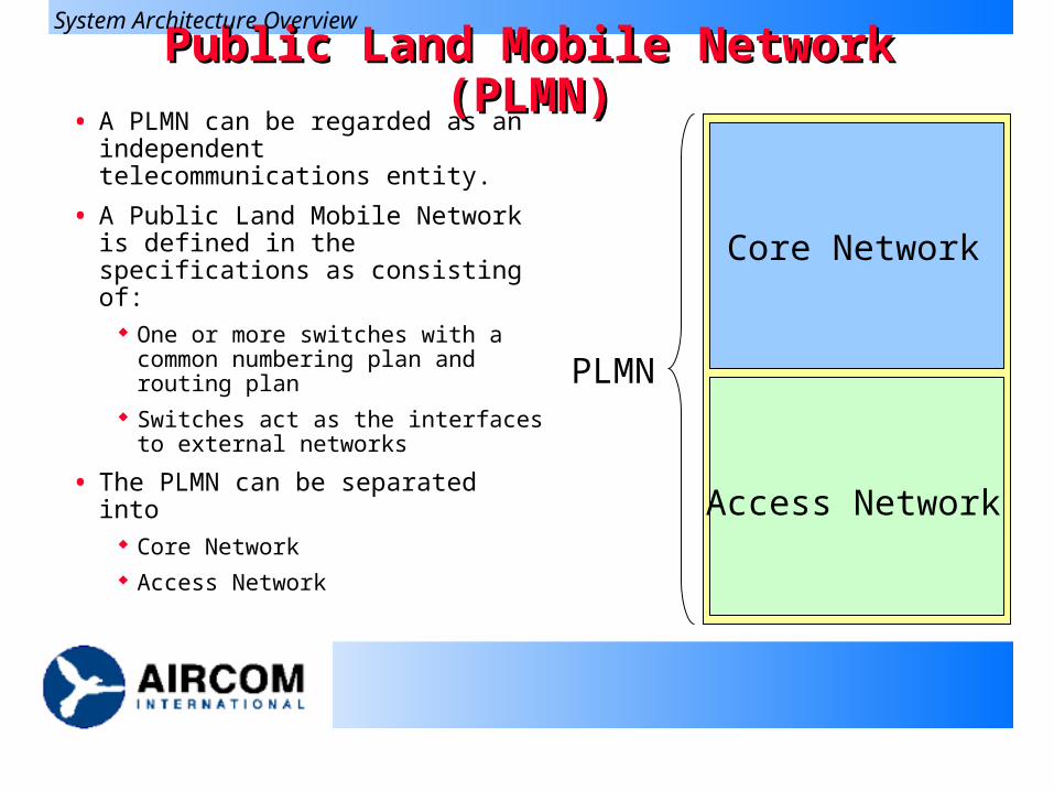
Public Land Mobile Network (PLMN)Public Land Mobile Network (PLMN)• A PLMN can be regarded as an
independent telecommunications entity.
• A Public Land Mobile Network is defined in the specifications as consisting of:
One or more switches with a common numbering plan and routing plan
Switches act as the interfaces to external networks
• The PLMN can be separated into Core Network Access Network
Core Network
Access Network
PLMN
System Architecture Overview
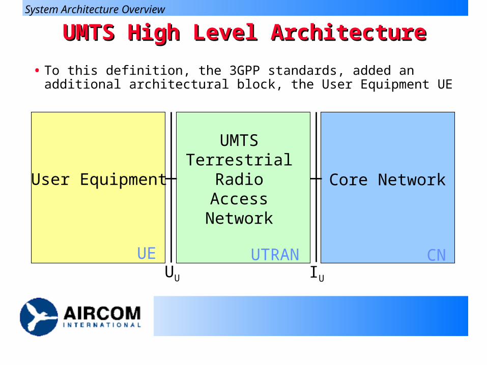
User Equipment
UMTS Terrestrial
Radio Access Network
Core Network
UU IU
UE UTRAN CN
UMTS High Level ArchitectureUMTS High Level Architecture
• To this definition, the 3GPP standards, added an additional architectural block, the User Equipment UE
System Architecture Overview
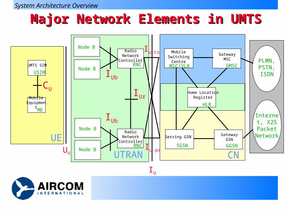
Major Network Elements in UMTSMajor Network Elements in UMTS
PLMN, PSTN, ISDN
Internet, X25
Packet Network
UU
UE
CU
USIM
ME
Mobile Equipment
UMTS SIM
CN
MSC/VLR
SGSN GGSN
GMSC
HLR
Serving GSN Gateway GSN
Gateway MSC
Mobile Switching Centre
Home Location Register
System Architecture Overview
IU
UTRAN
IUb
IUr
Node B
Node B
Node B
Node B
RNC
RNC
Radio Network Controller
Radio Network Controller
Iu-ps
Iu-cs
IUb
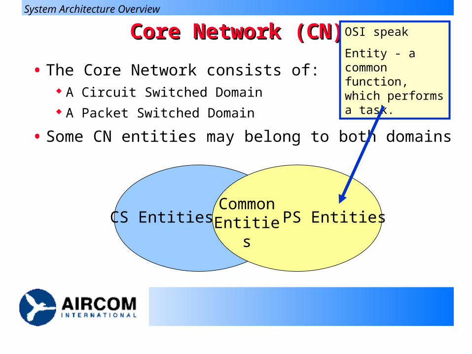
Core Network (CN)Core Network (CN)
• The Core Network consists of: A Circuit Switched Domain A Packet Switched Domain
• Some CN entities may belong to both domains
CS Entities PS EntitiesCommon Entities
System Architecture Overview
OSI speak
Entity - a common function, which performs a task.
Functions of the CNFunctions of the CN
• Switching
• Service Provision
• Transmission of user traffic between UTRAN and/or fixed network
• Mobility Management
• Operations, Administration and Maintenance
System Architecture Overview
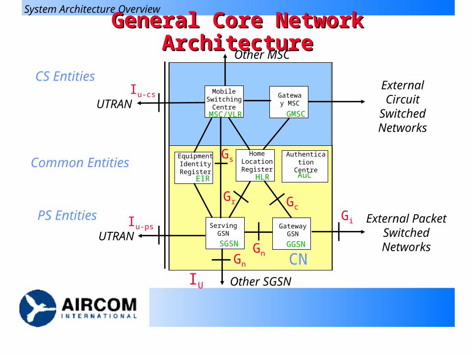
General Core Network ArchitectureGeneral Core Network Architecture
IU
CN
MSC/VLR
SGSN GGSN
GMSC
HLR
Serving GSN
Gateway GSN
Gateway MSC
Mobile Switching
Centre
Home Location Register
Other SGSN
Other MSC
UTRAN
UTRAN
External Circuit
Switched Networks
External Packet Switched Networks
Iu-cs
Iu-ps
Gs
GnGn
Gr GcGi
Authentication Centre
AuC
Equipment Identity Register
EIR
CS Entities
Common Entities
PS Entities
System Architecture Overview
Major Elements of the Core NetworkMajor Elements of the Core Network
• Home Location Register (HLR)
The database storing the master copy of a users profile
• Visitor Location Register (VLR)
The database holding a copy of a visiting users profile
• Mobile Switching Centre (MSC)
Switch for Circuit Switched Services
• Gateway MSC (GMSC)
• Serving GPRS Support Node (SGSN)
Router for Packet Switched Services
• Gateway GPRS Support Node (GGSN)
System Architecture Overview
Shared Entities in the Core NetworkShared Entities in the Core Network
• All of the following entities are shared between the CS and PS domains:
Home Location Register
Authentication Centre
Equipment Identity Register
SMS-Service Centre
System Architecture Overview
Why Separate CS domains and PS domains?Why Separate CS domains and PS domains?
• Advantages of separation Simple evolution from
GSM/GPRS Low Risk Early Availability Service Continuity
• Disadvantages of separation Build and manage 2
networks Separate engineering and
dimensioning Greater Infrastructure Cost Duplicated Functions
Mobility Management in VLR and SGSN
System Architecture Overview
Suggest some general advantages and disadvantages.
Circuit Switched DomainCircuit Switched Domain
• The CS domain deals with circuit switched type
connections and the associated signalling
Connections that require a dedicated resource
• Entities specific to the CS domain are:
MSC - mobile services switching centre
GMSC - gateway MSC
VLR - visitor location register
System Architecture Overview
Packet Switched DomainPacket Switched Domain
• The PS domain deals with packet switched type
connections and associated signalling
Comprised of packets, each of which can be routed
independently over virtual routes.
• Entities specific to the PS domain are:
SGSN - Serving GPRS support node
GGSN - Gateway GPRS support node
System Architecture Overview
UMTS System AreasUMTS System Areas
• Location Area
UEs registered on the CS domain report their
position in terms of a Location Area
UEs in idle mode monitor Location Area Identities
(LAIs) and report changes
Stored in the visitor location register, VLR
System Architecture Overview
UMTS System AreasUMTS System Areas
• Routing Area RA
UE’s registered on the PS domain report their position
in terms of a Routing Area
UE’s in both idle and connected mode monitor Routing
Area Identities (RAIs) and support changes
Stored in the Gateway GPRS support node, SGSN
System Architecture Overview
UMTS System AreasUMTS System Areas
• UTRAN Registration Area
Used when a signalling/traffic connection is
established
A subset of the Routing Area
Only relevant to PS mode of operation
Used by the radio network controller RNC
System Architecture Overview
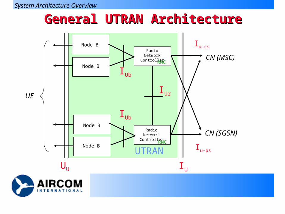
General UTRAN ArchitectureGeneral UTRAN Architecture
UU IU
UE
UTRAN
IUb
IUr
Node B
Node B
Node B
Node B
RNC
RNC
Radio Network Controller
Radio Network Controller
Iu-ps
Iu-cs
IUb
CN (MSC)
CN (SGSN)
System Architecture Overview
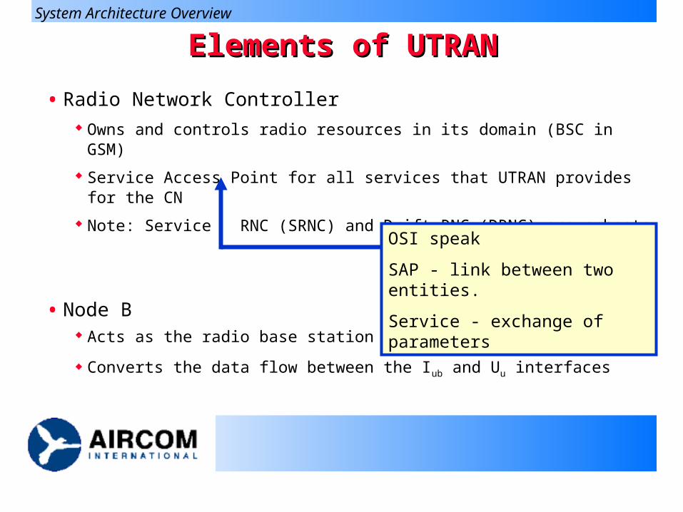
Elements of UTRANElements of UTRAN
• Radio Network Controller Owns and controls radio resources in its domain (BSC in GSM)
Service Access Point for all services that UTRAN provides for the CN
Note: Service RNC (SRNC) and Drift RNC (DRNC) are subsets
• Node B Acts as the radio base station (BTS in GSM)
Converts the data flow between the Iub and Uu interfaces
System Architecture Overview
OSI speak
SAP - link between two entities.
Service - exchange of parameters
Functions of UTRANFunctions of UTRAN
• Provision of Radio Management & Control
• System access control
• Security and privacy
• Handover (Hard and Soft)
System Architecture Overview
Provision of Radio Management & ControlProvision of Radio Management & Control
• Radio bearer set up and release (RNC and UE)
• Allocation and release of physical radio channels (UTRAN)
• Allocation of downlink channelisation codes (Controlling RNC ie: CRNC)
• Packet data transfer over radio function (UTRAN and UE)
• Radio channel coding and control (UTRAN and UE)
• Initial access detection and call handling (UTRAN)
• Power control Uplink Outer Loop (SRNC and Node B) All other control (UTRA and UE)
System Access ControlSystem Access Control
• Admission control (CRNC)
• Congestion control (UTRAN) RNC knows whether Node B has sufficient power
and spare codes
• System information broadcasting (UTRAN)
Security and PrivacySecurity and Privacy
• Use of temporary identifier
• RNTI- Radio Network Temporary ID (UTRAN)
• Encryption
HandoverHandover
• Radio environment survey (UTRAN-UE)
• Handover decision (RNC-UE)
• Macrodiversity control (SRNS-DRNS)
• Handover control (UTRAN)
• Handover (UTRAN or CN)
• SRNS relocation (RNC and CN)
• Inter-system handover (UTRAN, CN and UE)
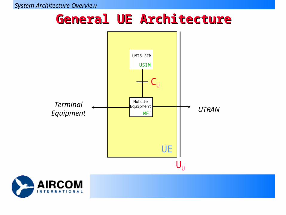
General UE ArchitectureGeneral UE Architecture
UU
UE
CU
USIM
ME
Mobile Equipment
UMTS SIM
UTRANTerminal
Equipment
System Architecture Overview
Functions of the UEFunctions of the UE
• Display and User interface
• Holds the authentication algorithms and keys
• User end termination of the air interface
• Application platform
System Architecture Overview
Elements of the UEElements of the UE
• Mobile Equipment The radio terminal used for radio communication over
the Uu interface
• UMTS Subscriber Identity Module The smartcard that holds the subscriber identity,
authentication and encryption keys etc
• Additionally the Terminal Equipment This carries the application specific user interface
System Architecture Overview
Major Interfaces in UMTSMajor Interfaces in UMTS
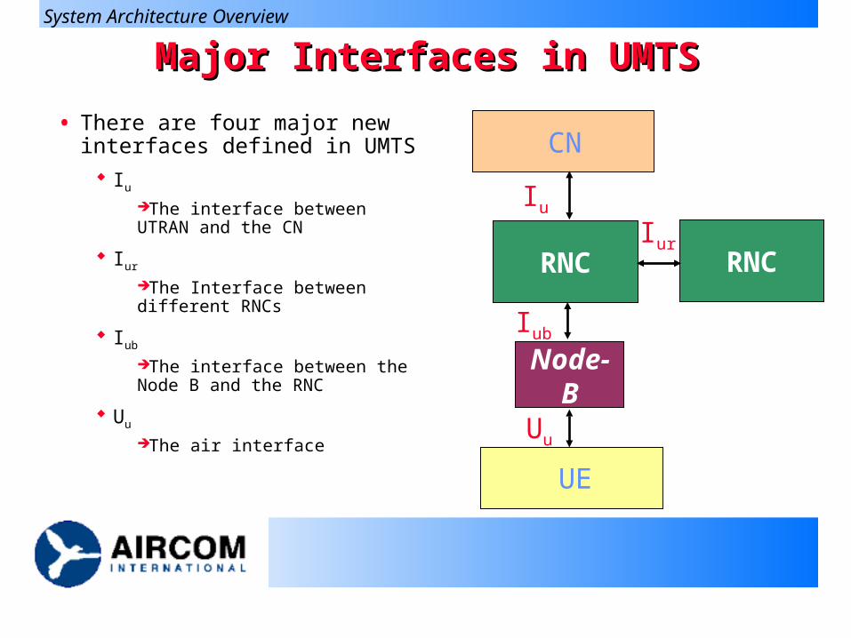
• There are four major new interfaces defined in UMTS
Iu
The interface between UTRAN and the CN
Iur
The Interface between different RNCs
Iub
The interface between the Node B and the RNC
Uu
The air interface
RNC
Node-B
RNC
UE
CN
Uu
Iu
Iub
Iur
System Architecture Overview
IIu u - the Core Network to UTRAN Interface- the Core Network to UTRAN Interface
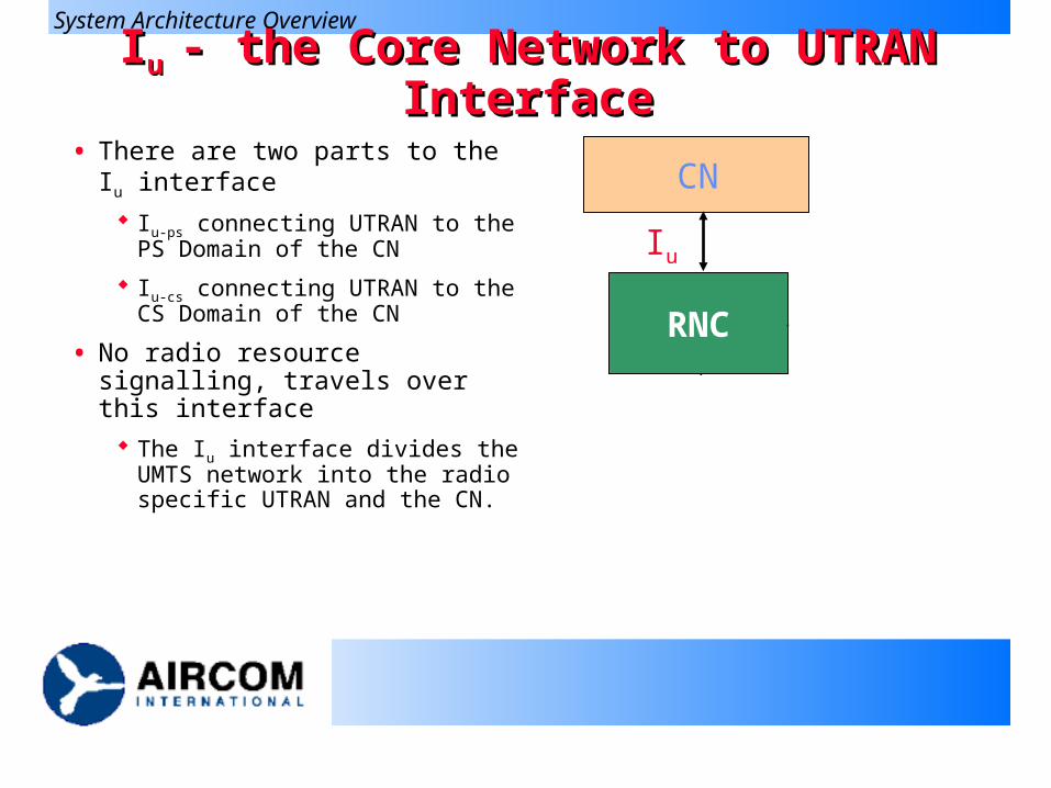
• There are two parts to the Iu interface
Iu-ps connecting UTRAN to the PS Domain of the CN
Iu-cs connecting UTRAN to the CS Domain of the CN
• No radio resource signalling, travels over this interface
The Iu interface divides the UMTS network into the radio specific UTRAN and the CN.
RNC
Node-B
RNC
UE
CN
Uu
Iu
Iub
Iur
System Architecture Overview
IIurur - the Inter-RNC Interface - the Inter-RNC Interface
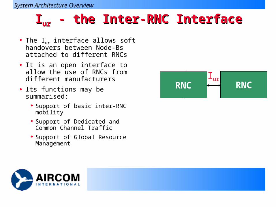
• The Iur interface allows soft handovers between Node-Bs attached to different RNCs
• It is an open interface to allow the use of RNCs from different manufacturers
• Its functions may be summarised: Support of basic inter-RNC
mobility Support of Dedicated and
Common Channel Traffic Support of Global Resource
Management
RNC
Node-B
RNC
UE
CN
Uu
Iu
Iub
Iur
System Architecture Overview
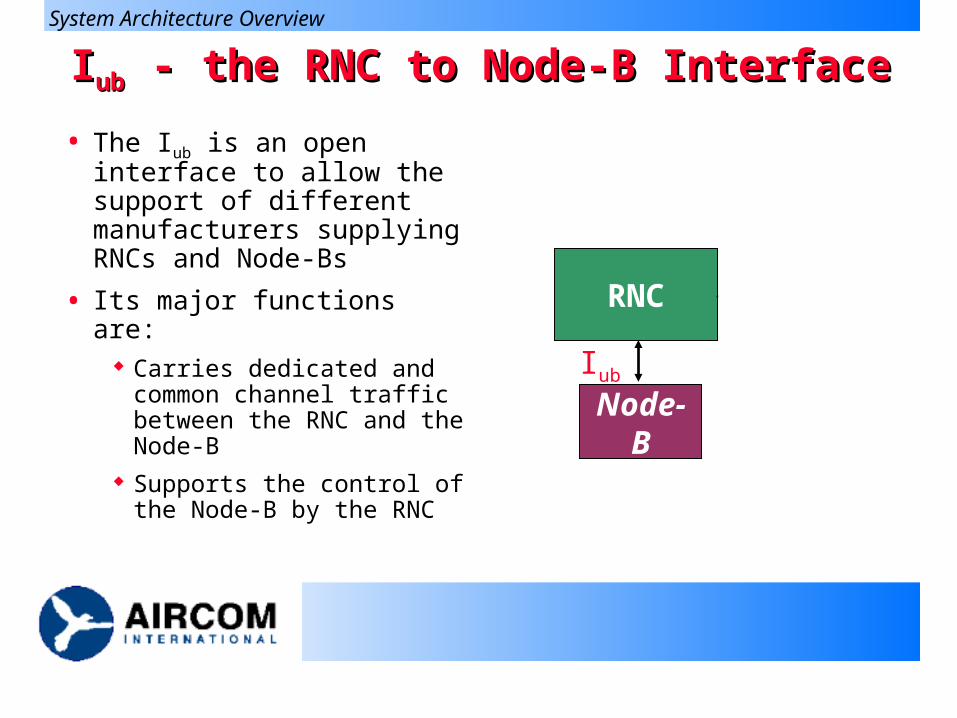
IIubub - the RNC to Node-B Interface - the RNC to Node-B Interface
• The Iub is an open interface to allow the support of different manufacturers supplying RNCs and Node-Bs
• Its major functions are: Carries dedicated and common
channel traffic between the RNC and the Node-B
Supports the control of the Node-B by the RNC
RNC
Node-B
RNC
UE
CN
Uu
Iu
Iub
Iur
System Architecture Overview
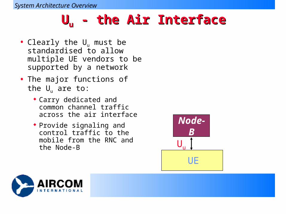
UUuu - the Air Interface - the Air Interface
• Clearly the Uu must be standardised to allow multiple UE vendors to be supported by a network
• The major functions of the Uu are to:
Carry dedicated and common channel traffic across the air interface
Provide signaling and control traffic to the mobile from the RNC and the Node-B
RNC
Node-B
RNC
UE
CN
Uu
Iu
Iub
Iur
System Architecture Overview
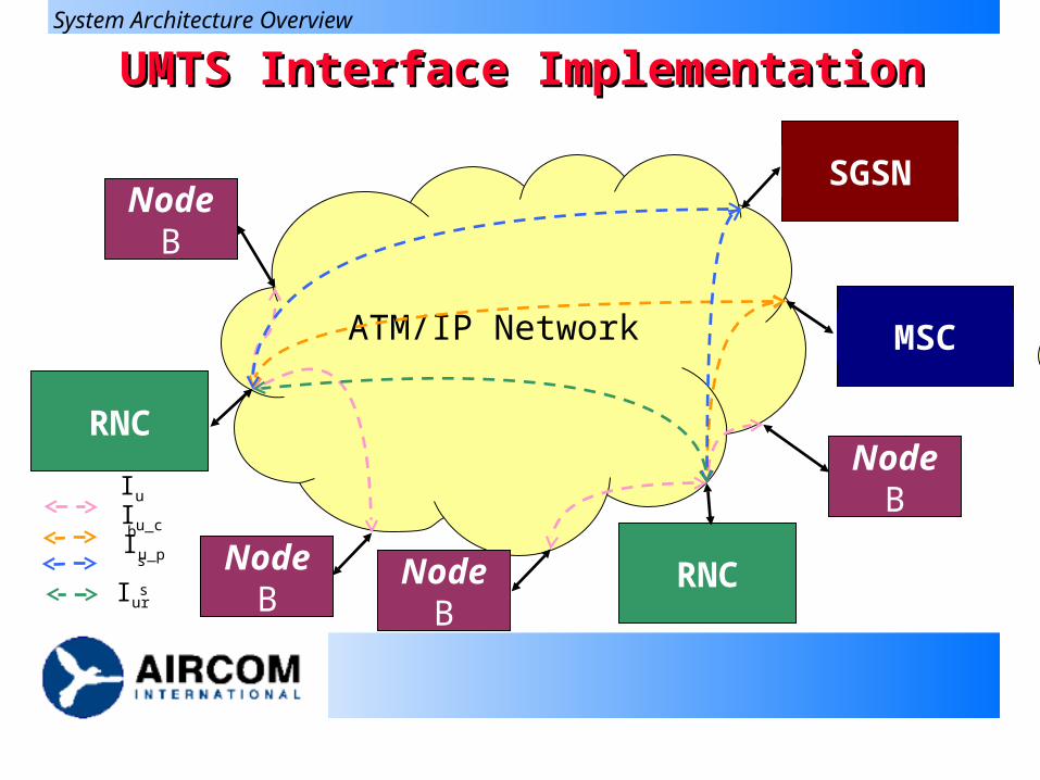
UMTS Interface ImplementationUMTS Interface Implementation
ATM/IP Network
RNCNode B
Node B
Node B
MSC
RNC
SGSN
Node B
Iub
Iu_cs
Iu_ps
Iur
System Architecture Overview
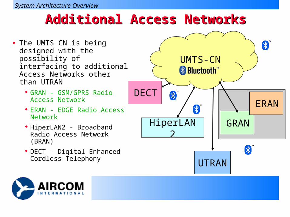
Additional Access NetworksAdditional Access Networks
• The UMTS CN is being designed with the possibility of interfacing to additional Access Networks other than UTRAN
GRAN - GSM/GPRS Radio Access Network
ERAN - EDGE Radio Access Network
HiperLAN2 - Broadband Radio Access Network (BRAN)
DECT - Digital Enhanced Cordless Telephony
UMTS-CN
DECT
HiperLAN2 GRAN
ERAN
UTRAN
System Architecture Overview
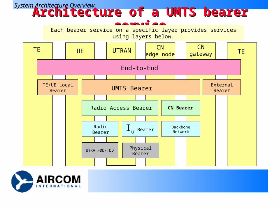
Architecture of a UMTS bearer serviceArchitecture of a UMTS bearer service
TE TEUE UTRAN CNedge node
CNgateway
End-to-End
TE/UE Local Bearer UMTS Bearer External Bearer
Radio Access Bearer CN Bearer
Radio Bearer Iu Bearer Backbone Network
UTRA FDD/TDD Physical Bearer
System Architecture Overview
Each bearer service on a specific layer provides services using layers below.
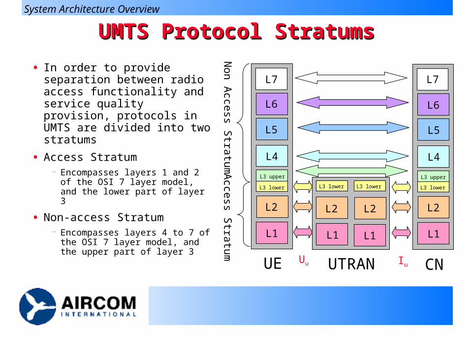
UMTS Protocol StratumsUMTS Protocol Stratums
• In order to provide separation between radio access functionality and service quality provision, protocols in UMTS are divided into two stratums
• Access Stratum Encompasses layers 1 and 2 of
the OSI 7 layer model, and the lower part of layer 3
• Non-access Stratum Encompasses layers 4 to 7 of
the OSI 7 layer model, and the upper part of layer 3
Non A
ccess Stratum
Access S
tratumL1 L1 L1L1
L2L2L2L2
L5L5
L4L4
L6 L6
L7 L7
L3 lower L3 lower L3 lower L3 lower
L3 upper L3 upper
Uu IuUE UTRAN CN
System Architecture Overview
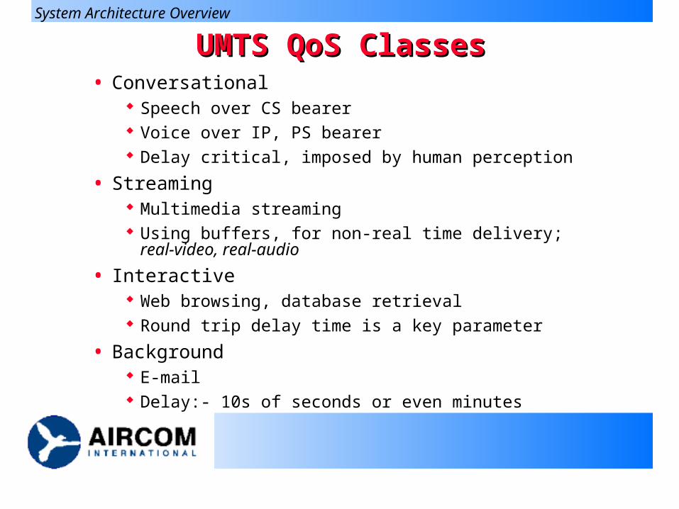
UMTS QoS ClassesUMTS QoS Classes• Conversational
Speech over CS bearer Voice over IP, PS bearer Delay critical, imposed by human perception
• Streaming Multimedia streaming Using buffers, for non-real time delivery; real-video, real-audio
• Interactive Web browsing, database retrieval Round trip delay time is a key parameter
• Background E-mail Delay:- 10s of seconds or even minutes
System Architecture Overview
UTRAN
UTRAN
UTRANUTRAN
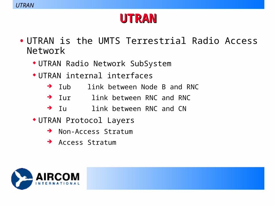
• UTRAN is the UMTS Terrestrial Radio Access Network UTRAN Radio Network SubSystem UTRAN internal interfaces
Iub link between Node B and RNC Iur link between RNC and RNC Iu link between RNC and CN
UTRAN Protocol Layers Non-Access Stratum Access Stratum
UTRAN
Radio Network Subsystem (RNS)Radio Network Subsystem (RNS)
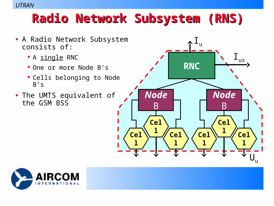
• A Radio Network Subsystem consists of:
A single RNC One or more Node B’s Cells belonging to Node B’s
• The UMTS equivalent of the GSM BSS
RNC
Node B
Cell
Cell
Cell
Node B
Cell
Cell
Cell
Iur
Iu
Uu
UTRAN
Radio Network Controller (RNC)Radio Network Controller (RNC)
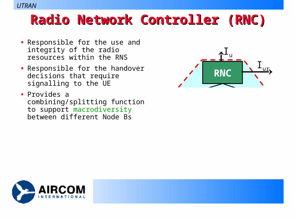
• Responsible for the use and integrity of the radio resources within the RNS
• Responsible for the handover decisions that require signalling to the UE
• Provides a combining/splitting function to support macrodiversity between different Node Bs
UTRAN
RNC
Node B
Cell
Cell
Cell
Node B
Cell
Cell
Cell
Iur
Iu
Uu
Node BNode B
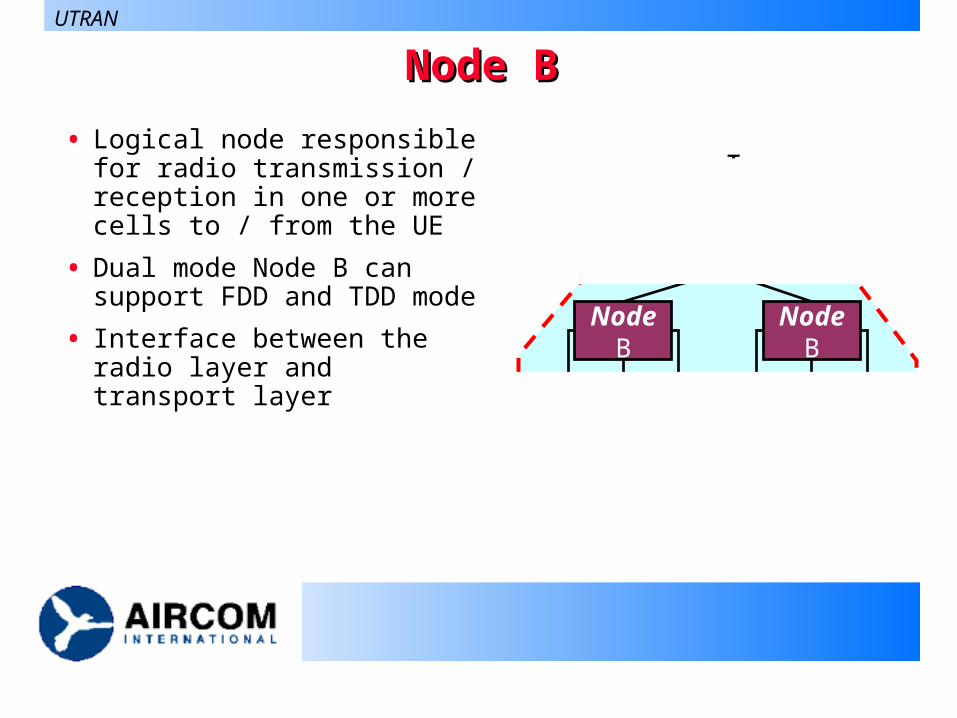
• Logical node responsible for radio transmission / reception in one or more cells to / from the UE
• Dual mode Node B can support FDD and TDD mode
• Interface between the radio layer and transport layer
UTRAN
RNC
Node B
Cell
Cell
Cell
Node B
Cell
Cell
Cell
Iur
Iu
Uu
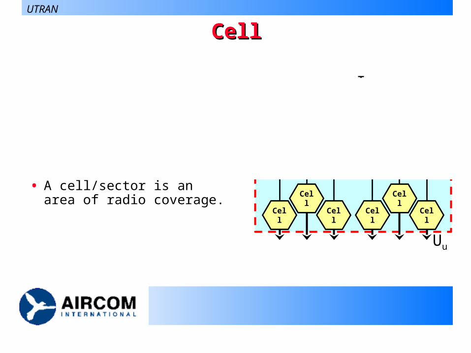
CellCell
• A cell/sector is an area of radio coverage.
RNC
Node B
Cell
Cell
Cell
Node B
Cell
Cell
Cell
Iur
Iu
Uu
UTRAN
Handover in UMTSHandover in UMTS
• There are three basic types of handover Intra frequency handovers
Handovers between 2 UMTS carriers at the same frequency These can be soft handovers
Inter frequency handovers Handovers between 2 UMTS carriers at different frequencies These are hard handovers
Inter system handovers Handovers between UMTS and GSM carriers These are hard handovers
UTRAN
Handover Sets in UMTSHandover Sets in UMTS
• Active Set Cells forming a soft handover connection to the mobile
• Candidate Set Cells not presently used in soft handover but who qualify
for soft handover based on Pilot, Ec/Io levels.
• Neighbour Set Those cells which are continuously monitored by the
mobile. The Pilot, Ec/Io levels are not strong enough to be added to the Active Set.
UTRAN
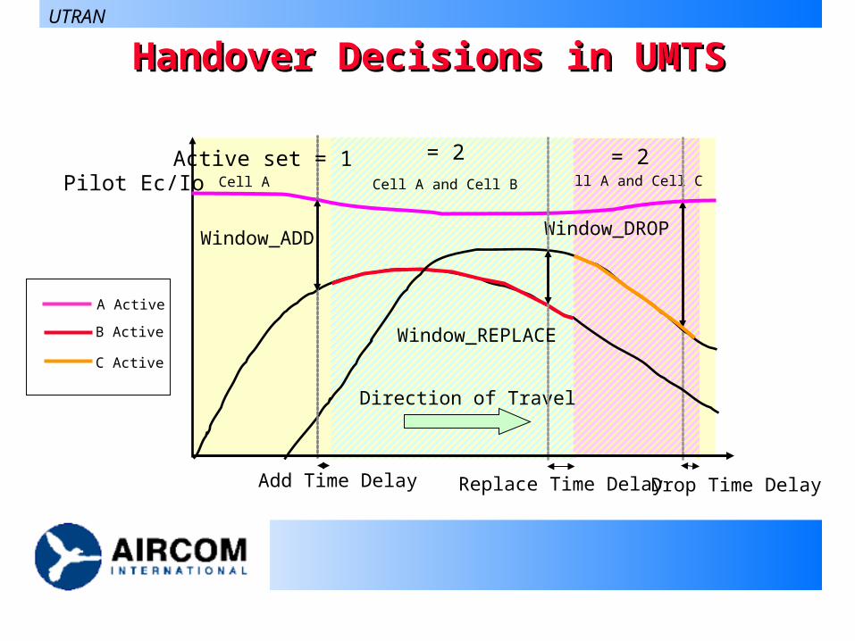
= 2Cell A and Cell C
= 2Cell A and Cell B
Handover Decisions in UMTSHandover Decisions in UMTS
Pilot Ec/Io
Direction of Travel
Window_DROP
Drop Time Delay
Window_ADD
Add Time Delay Replace Time Delay
Window_REPLACE
Active set = 1Cell A
UTRAN
A Active
B Active
C Active
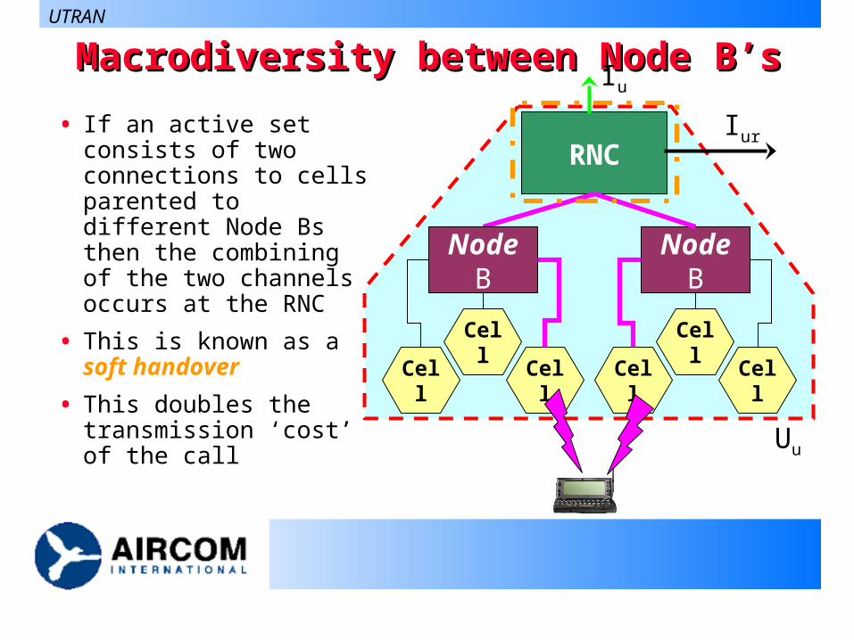
Macrodiversity between Node B’sMacrodiversity between Node B’s
• If an active set consists of two connections to cells parented to different Node Bs then the combining of the two channels occurs at the RNC
• This is known as a soft handover
• This doubles the transmission ‘cost’ of the call
RNC
Node B
Cell
Cell
Cell
Node B
Cell
Cell
Cell
Iur
Iu
Uu
UTRAN
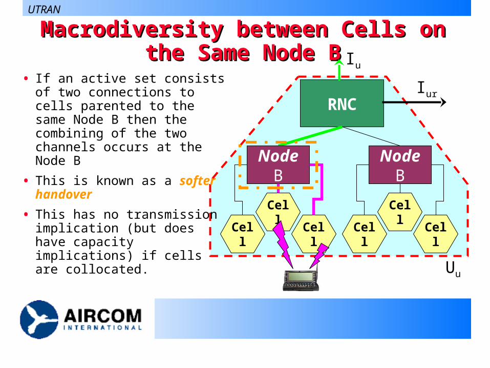
Macrodiversity between Cells on the Macrodiversity between Cells on the Same Node BSame Node B
RNC
Node B
Cell
Cell
Cell
Node B
Cell
Cell
Cell
Iur
Iu
Uu
• If an active set consists of two connections to cells parented to the same Node B then the combining of the two channels occurs at the Node B
• This is known as a softer handover
• This has no transmission implication (but does have capacity implications) if cells are collocated.
UTRAN
Protocol Model for UTRAN InterfacesProtocol Model for UTRAN Interfaces
• Protocol structures in UTRAN are designed in layers
and planes.
• They are seen as logically independent of each
other
However they will physically interact.
• Being logically independent allows for changes to
blocks in the future,
UTRAN
theoretically!
General Protocol Model for General Protocol Model for UTRAN Terrestrial InterfacesUTRAN Terrestrial Interfaces
UTRAN
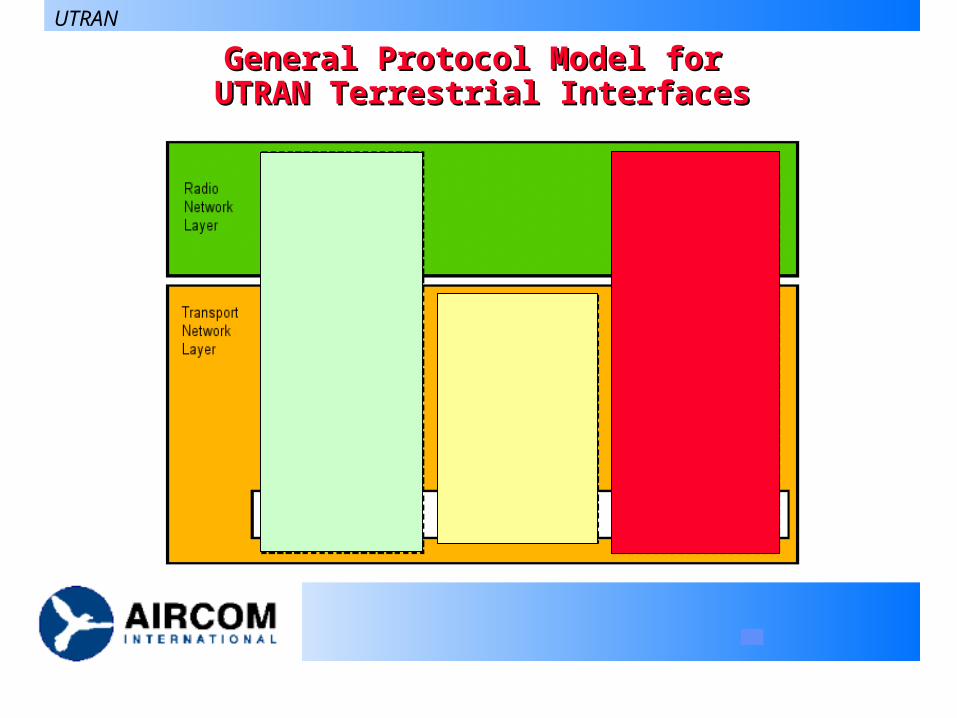
Horizontal Layers in the General Protocol ModelHorizontal Layers in the General Protocol Model
• All UTRAN related issues are only visible in the
Radio Network Layer
• The Transport Layer simply represents standard
transport technology for use in UTRAN
e.g. ATM and appropriate ATM Adaptation Layers AAL2 ( voice ) and AAL5 ( data )
UTRAN
Vertical Planes in the General Protocol ModelVertical Planes in the General Protocol Model
• The Control Plane is provided for all UMTS specific
control signalling including:
Application Protocols
Signalling Bearers
• The User Plane is provided for all data sent and
received by the user including:
Data Streams
Data Bearers
UTRAN
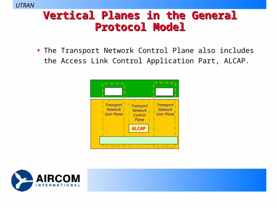
Vertical Planes in the General Protocol ModelVertical Planes in the General Protocol Model
• The Transport Network Control Plane also includes the Access
Link Control Application Part, ALCAP.
UTRAN
Transport Network
User Plane
Transport Network
User Plane
Transport Network Control Plane
ALCAP
ALCAP - Access Link Control Application PartALCAP - Access Link Control Application Part
• ALCAP sets up the transport bearers for the User Plane
• The independence of the User and Control Plane
assumes that an ALCAP signalling transaction takes
place.
UTRAN
Iu, the UTRAN-CN InterfaceIu, the UTRAN-CN Interface
• The Iu has two different instances.
Iu-CS for circuit switched connections
Iu_PS for packet switched connections
• Originally proposed as one interface but the
differences between circuit and packet switched
services has produced two.
• The Control plane is the same as far as possible!
UTRAN
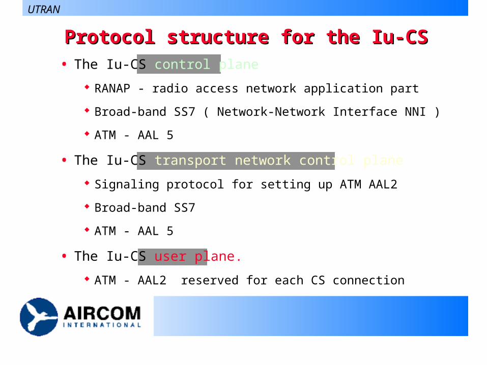
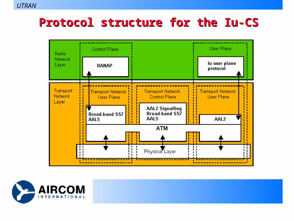
• The Iu-CS control plane
RANAP - radio access network application part
Broad-band SS7 ( Network-Network Interface NNI )
ATM - AAL 5
• The Iu-CS transport network control plane
Signaling protocol for setting up ATM AAL2
Broad-band SS7
ATM - AAL 5
• The Iu-CS user plane.
ATM - AAL2 reserved for each CS connection
Protocol structure for the Iu-CSProtocol structure for the Iu-CS
UTRAN
Protocol structure for the Iu-CSProtocol structure for the Iu-CS
UTRAN
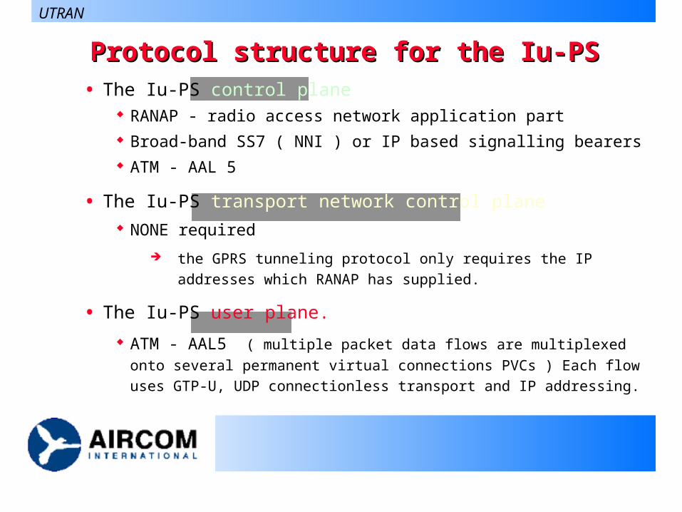
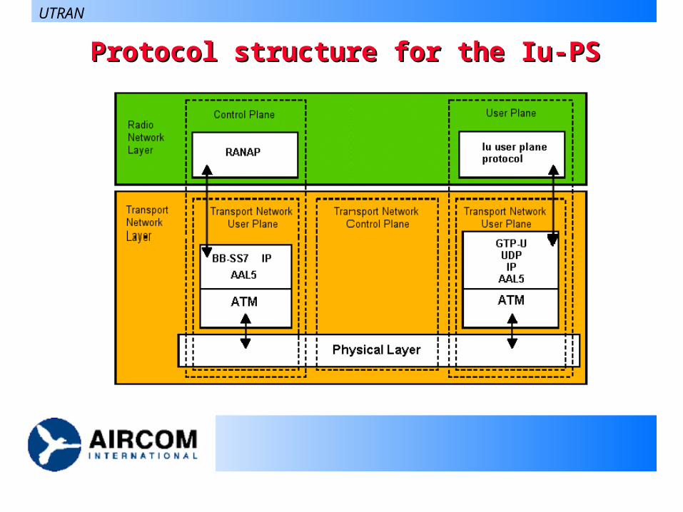
Protocol structure for the Iu-PSProtocol structure for the Iu-PS• The Iu-PS control plane
RANAP - radio access network application part Broad-band SS7 ( NNI ) or IP based signalling bearers ATM - AAL 5
• The Iu-PS transport network control plane NONE required
the GPRS tunneling protocol only requires the IP addresses which
RANAP has supplied.
• The Iu-PS user plane.
ATM - AAL5 ( multiple packet data flows are multiplexed onto several
permanent virtual connections PVCs ) Each flow uses GTP-U, UDP
connectionless transport and IP addressing.
UTRAN
Protocol structure for the Iu-PSProtocol structure for the Iu-PS
UTRAN
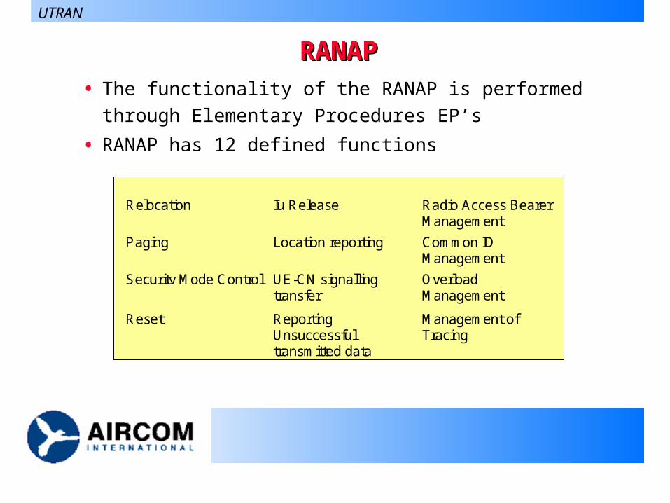
RANAPRANAP• The functionality of the RANAP is performed through
Elementary Procedures EP’s
• RANAP has 12 defined functions
UTRAN
Relocation Iu Release Radio Access BearerManagement
Paging Location reporting Common IDManagement
Security Mode Control UE-CN signallingtransfer
OverloadManagement
Reset ReportingUnsuccessfultransmitted data
Management ofTracing
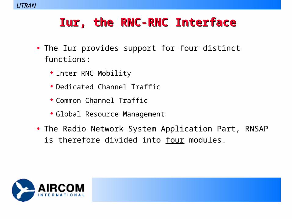
Iur, the RNC-RNC InterfaceIur, the RNC-RNC Interface
• The Iur provides support for four distinct functions:
Inter RNC Mobility
Dedicated Channel Traffic
Common Channel Traffic
Global Resource Management
• The Radio Network System Application Part, RNSAP is
therefore divided into four modules.
UTRAN
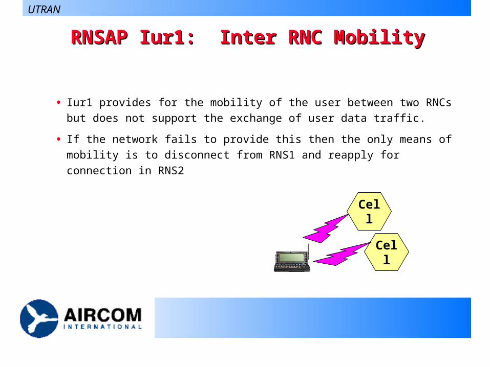
RNSAP Iur1: Inter RNC MobilityRNSAP Iur1: Inter RNC Mobility
• Iur1 provides for the mobility of the user between two RNCs but
does not support the exchange of user data traffic.
• If the network fails to provide this then the only means of mobility
is to disconnect from RNS1 and reapply for connection in RNS2
UTRAN
Cell
Cell
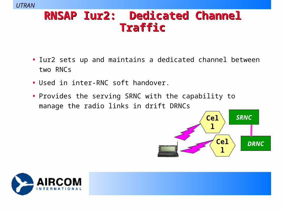
RNSAP Iur2: Dedicated Channel TrafficRNSAP Iur2: Dedicated Channel Traffic
• Iur2 sets up and maintains a dedicated channel between two RNCs
• Used in inter-RNC soft handover.
• Provides the serving SRNC with the capability to manage the radio
links in drift DRNCs
UTRAN
Cell
CellSRNC
DRNC
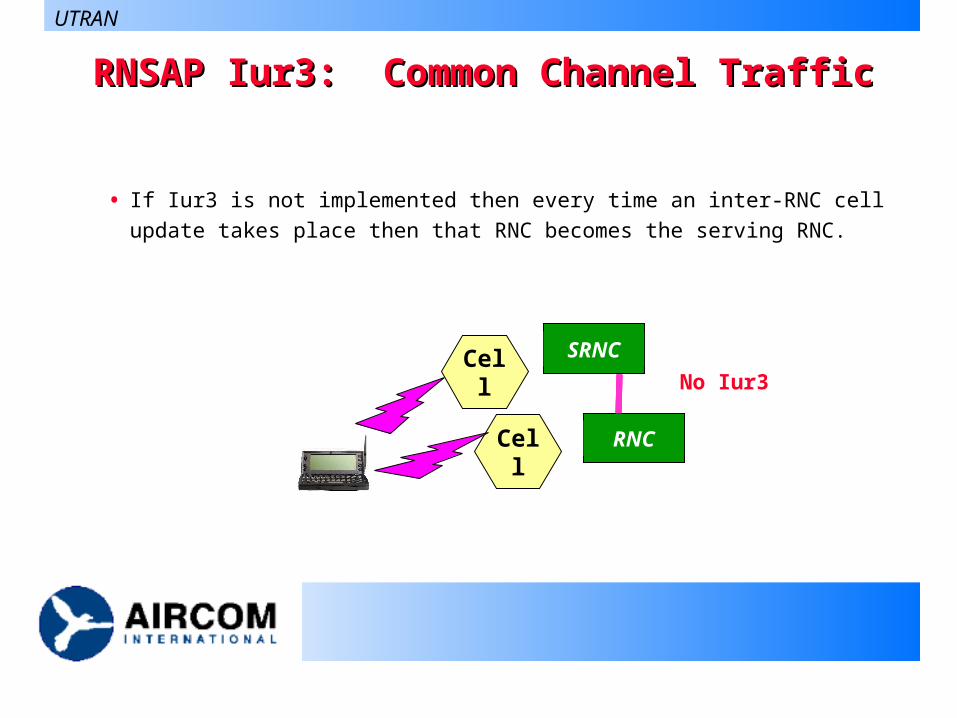
RNSAP Iur3: Common Channel TrafficRNSAP Iur3: Common Channel Traffic
• If Iur3 is not implemented then every time an inter-RNC cell
update takes place then that RNC becomes the serving RNC.
UTRAN
Cell
CellSRNC
RNC
RNC
SRNC
SRNC
RNC
No Iur3
RNSAP Iur4: Global Resource ManagementRNSAP Iur4: Global Resource Management
• This function is considered optionally as it does not transmit
any user data across the Iur.
• However it does provide useful information
transfer of cell measurement between RNCs
transfer of Node B timing information between RNCs
UTRAN
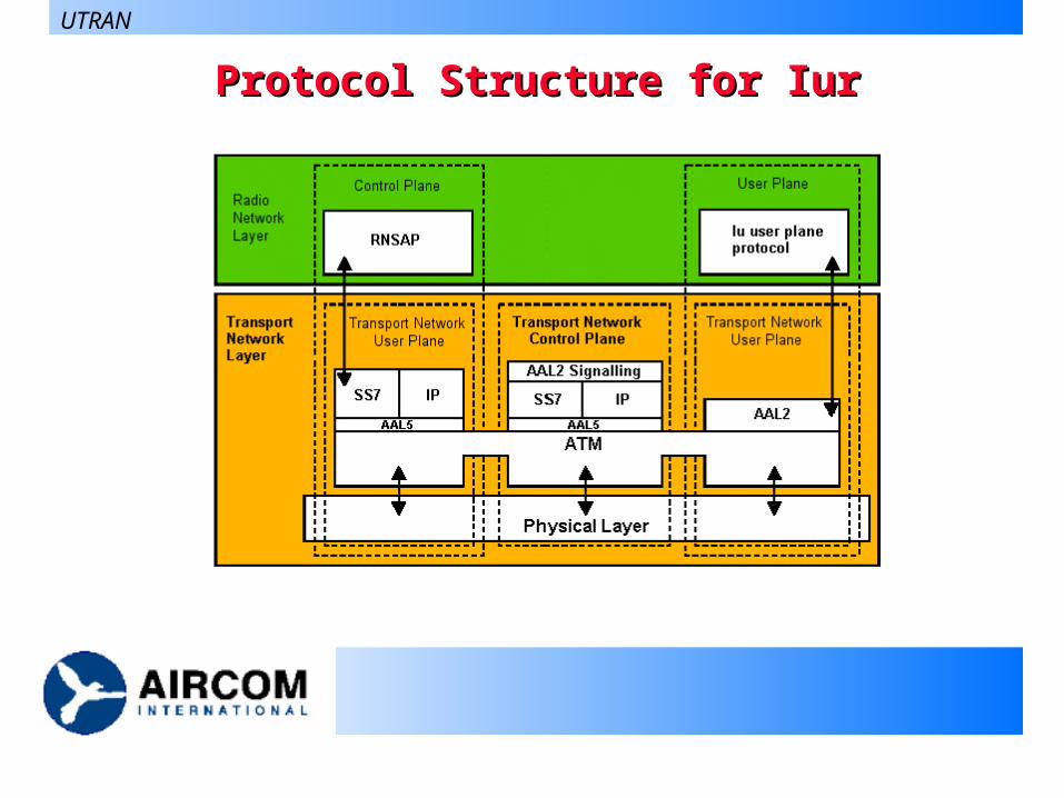
Protocol Structure for IurProtocol Structure for Iur
UTRAN
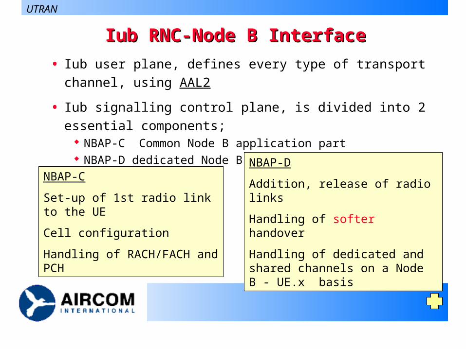
Iub RNC-Node B InterfaceIub RNC-Node B Interface
• Iub user plane, defines every type of transport channel, using
AAL2
• Iub signalling control plane, is divided into 2 essential
components; NBAP-C Common Node B application part NBAP-D dedicated Node B application part
UTRAN
NBAP-C
Set-up of 1st radio link to the UE
Cell configuration
Handling of RACH/FACH and PCH
NBAP-D
Addition, release of radio links
Handling of softer handover
Handling of dedicated and shared channels on a Node B - UE.x basis
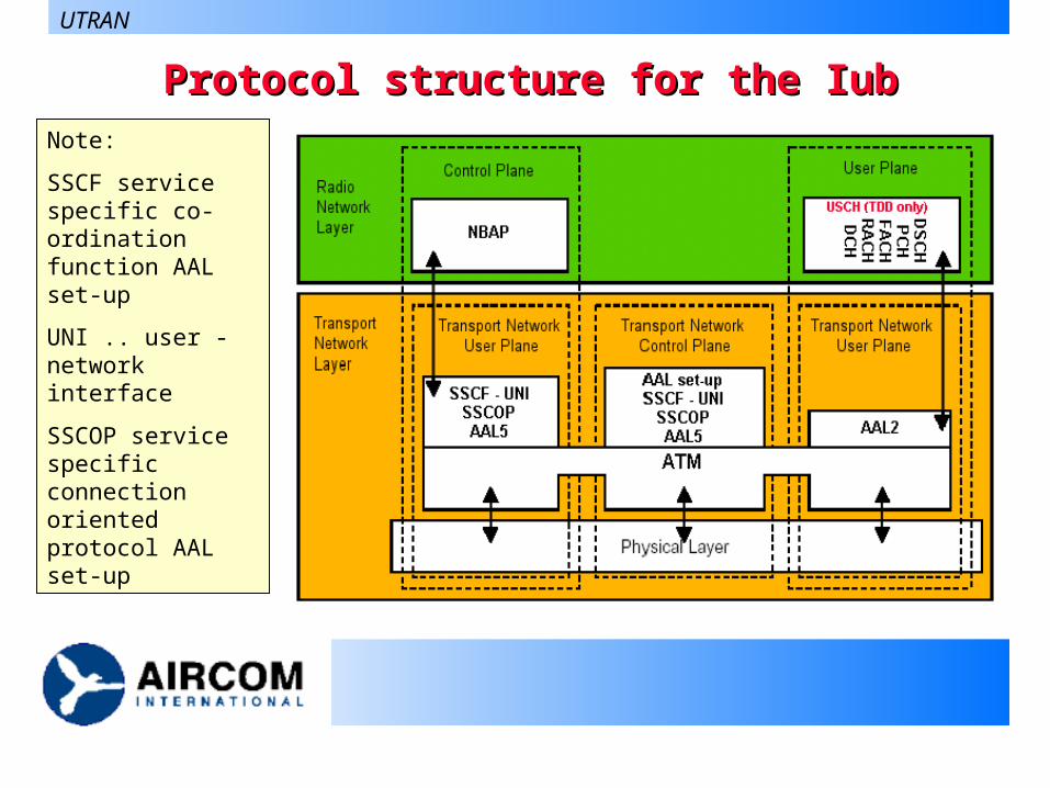
Protocol structure for the IubProtocol structure for the Iub
UTRAN
Note:
SSCF service specific co-ordination function AAL set-up
UNI .. user - network interface
SSCOP service specific connection oriented protocol AAL set-up