ts 126 132 - v4.1.0 - universal mobile telecommunications ... · a stand-alone service or as the...
TRANSCRIPT

ETSI TS 126 132 V4.1.0 (2001-09)
Technical Specification
Universal Mobile Telecommunications System (UMTS);Narrow band (3,1 kHz) speech and video telephony
terminal acoustic test specification(3GPP TS 26.132 version 4.1.0 Release 4)
ETSI
ETSI TS 126 132 V4.1.0 (2001-09)13GPP TS 26.132 version 4.1.0 Release 4
Reference RTS/TSGS-0426132Uv4R1
Keywords UMTS
ETSI
650 Route des Lucioles F-06921 Sophia Antipolis Cedex - FRANCE
Tel.: +33 4 92 94 42 00 Fax: +33 4 93 65 47 16
Siret N° 348 623 562 00017 - NAF 742 C
Association à but non lucratif enregistrée à la Sous-Préfecture de Grasse (06) N° 7803/88
Important notice
Individual copies of the present document can be downloaded from: http://www.etsi.org
The present document may be made available in more than one electronic version or in print. In any case of existing or perceived difference in contents between such versions, the reference version is the Portable Document Format (PDF).
In case of dispute, the reference shall be the printing on ETSI printers of the PDF version kept on a specific network drive within ETSI Secretariat.
Users of the present document should be aware that the document may be subject to revision or change of status. Information on the current status of this and other ETSI documents is available at
http://portal.etsi.org/tb/status/status.asp
If you find errors in the present document, send your comment to: [email protected]
Copyright Notification
No part may be reproduced except as authorized by written permission. The copyright and the foregoing restriction extend to reproduction in all media.
© European Telecommunications Standards Institute 2001.
All rights reserved.
ETSI
ETSI TS 126 132 V4.1.0 (2001-09)23GPP TS 26.132 version 4.1.0 Release 4
Intellectual Property Rights IPRs essential or potentially essential to the present document may have been declared to ETSI. The information pertaining to these essential IPRs, if any, is publicly available for ETSI members and non-members, and can be found in ETSI SR 000 314: "Intellectual Property Rights (IPRs); Essential, or potentially Essential, IPRs notified to ETSI in respect of ETSI standards", which is available from the ETSI Secretariat. Latest updates are available on the ETSI Web server (http://www.etsi.org/legal/home.htm).
Pursuant to the ETSI IPR Policy, no investigation, including IPR searches, has been carried out by ETSI. No guarantee can be given as to the existence of other IPRs not referenced in ETSI SR 000 314 (or the updates on the ETSI Web server) which are, or may be, or may become, essential to the present document.
Foreword This Technical Specification (TS) has been produced by ETSI 3rd Generation Partnership Project (3GPP).
The present document may refer to technical specifications or reports using their 3GPP identities, UMTS identities or GSM identities. These should be interpreted as being references to the corresponding ETSI deliverables.
The cross reference between GSM, UMTS, 3GPP and ETSI identities can be found under www.etsi.org/key .
ETSI
ETSI TS 126 132 V4.1.0 (2001-09)33GPP TS 26.132 version 4.1.0 Release 4
Contents
Intellectual Property Rights ................................................................................................................................2
Foreword.............................................................................................................................................................2
Foreword.............................................................................................................................................................5
Introduction ........................................................................................................................................................5
1 Scope ........................................................................................................................................................6
2 References ................................................................................................................................................6
3 Definitions, symbols and abbreviations ...................................................................................................7 3.1 Definitions..........................................................................................................................................................7 3.2 Abbreviations .....................................................................................................................................................7
4 Interfaces ..................................................................................................................................................8 4.1 Narrow-band telephony......................................................................................................................................8 4.2 Wideband telephony...........................................................................................................................................8
5 Test configurations...................................................................................................................................8 5.1 Test setup for terminals ......................................................................................................................................8 5.1.1 Setup for handset terminals...........................................................................................................................9 5.1.2 Setup for headset terminals...........................................................................................................................9 5.1.3 Setup for hands-free terminals ....................................................................................................................10 5.1.3.1 Vehicle mounted hands-free..................................................................................................................10 5.1.3.2 Desktop operated hands-free.................................................................................................................11 5.1.3.3 Handheld hands-free .............................................................................................................................11 5.1.4 Position and calibration of HATS...............................................................................................................12 5.2 Setup of the electrical interfaces.......................................................................................................................12 5.2.1 Codec approach and specification.........................................................................................................12 5.2.2 Direct digital processing approach........................................................................................................12 5.3 Accuracy of test equipment ........................................................................................................................13 5.4 Test signals.......................................................................................................................................................13
6 Test conditions .......................................................................................................................................13 6.1 Environmental conditions.................................................................................................................................13 6.1.1 Handset and headset terminals....................................................................................................................13 6.1.2 Hands-free terminals..................................................................................................................................14 6.2 System Simulator conditions............................................................................................................................14 7 Narrow-band telephony transmission performance test methods.....................................................................14 7.1 Applicability.....................................................................................................................................................14 7.2 Overall loss/loudness ratings............................................................................................................................15 7.2.1 General........................................................................................................................................................15 7.2.2 Connections with handset UE.....................................................................................................................15 7.2.2.1 Sending Loudness Rating (SLR)...........................................................................................................15 7.2.2.2 Receiving Loudness Rating (RLR) .......................................................................................................15 7.2.3 Connections with Vehicle Mounted & Desk-Top hands-free UE...............................................................15 7.2.3.1 Sending Loudness Rating (SLR)...........................................................................................................16 7.2.3.2 Receiving Loudness Rating (RLR) .......................................................................................................16 7.2.4 Connections with Handheld hands-free UE................................................................................................16 7.2.4.1 Sending Loudness Rating (SLR)...........................................................................................................16 7.2.4.2 Receiving Loudness Rating (RLR) .......................................................................................................17 7.2.5 Connections with headset UE .....................................................................................................................17 7.3 Idle channel noise (handset and headset UE) ...................................................................................................17 7.3.1 Sending .......................................................................................................................................................17 7.3.2 Receiving ....................................................................................................................................................17 7.4 Sensitivity/frequency characteristics ................................................................................................................18 7.4.1 Handset UE sending...................................................................................................................................18 7.4.2 Handset UE receiving ................................................................................................................................18
ETSI
ETSI TS 126 132 V4.1.0 (2001-09)43GPP TS 26.132 version 4.1.0 Release 4
7.4.3 Vehicle Mounted & Desk-Top hands-free UE sending ..............................................................................18 7.4.4 Vehicle Mounted & Desk-Top hands-free UE receiving............................................................................19 7.4.5 Hand-Held hands-free UE sending .............................................................................................................19 7.4.6 Hand-Held hands-free UE receiving...........................................................................................................19 7.5 Sidetone characteristics ....................................................................................................................................20 7.5.1 Connections with Handset UE ....................................................................................................................20 7.5.2 Headset UE .................................................................................................................................................20 7.5.3 Hands-free UE (all categories)....................................................................................................................20 7.6 Stability loss .....................................................................................................................................................20 7.7 Acoustic echo control .......................................................................................................................................21 7.7.1 General........................................................................................................................................................21 7.7.2 Acoustic echo control in a Hands-free UE.................................................................................................21 7.7.3 Acoustic echo control in a handset UE .......................................................................................................21 7.7.4 Acoustic echo control in a headset UE .......................................................................................................22 7.8 Distortion..........................................................................................................................................................23 7.8.1 Sending Distortion ......................................................................................................................................23 7.8.2 Receiving..........................................................................................................................................................23 7.9 Ambient Noise Rejection .................................................................................................................................24
8 Wideband telephony transmission performance ....................................................................................25 8.1 Applicability.....................................................................................................................................................25
Annex A (informative): Change history ...............................................................................................26
History ..............................................................................................................................................................27
ETSI
ETSI TS 126 132 V4.1.0 (2001-09)53GPP TS 26.132 version 4.1.0 Release 4
Foreword This Technical Specification has been produced by the 3GPP.
The contents of the present document are subject to continuing work within the TSG and may change following formal TSG approval. Should the TSG modify the contents of this TS, it will be re-released by the TSG with an identifying change of release date and an increase in version number as follows:
Version x.y.z
where:
x the first digit:
1 presented to TSG for information;
2 presented to TSG for approval;
3 or greater indicates TSG approved document under change control.
y the second digit is incremented for all changes of substance, i.e. technical enhancements, corrections, updates, etc.
z the third digit is incremented when editorial only changes have been incorporated in the specification.
Introduction The present document specifies test methods to allow the minimum performance requirements for the acoustic characteristics of 3G terminals when used to provide narrow-band or wideband telephony to be assessed.
The objective for narrow-band services is to reach a quality as close as possible to ITU-T standards for PSTN circuits. However, due to technical and economic factors, there cannot be full compliance with the general characteristics of international telephone connections and circuits recommended by the ITU-T.
The performance requirements are specified in TS26.131; the test methods and considerations are specified in the main body of the text.

ETSI
ETSI TS 126 132 V4.1.0 (2001-09)63GPP TS 26.132 version 4.1.0 Release 4
1 Scope The present document is applicable to any terminal capable of supporting narrow-band or wideband telephony, either as a stand-alone service or as the telephony component of a multimedia service. The present document specifies test methods to allow the minimum performance requirements for the acoustic characteristics of 3G terminals when used to provide narrow-band or wideband telephony to be assessed.
2 References The following documents contain provisions which, through reference in this text, constitute provisions of the present document.
• References are either specific (identified by date of publication, edition number, version number, etc.) or non-specific.
• For a specific reference, subsequent revisions do not apply.
• For a non-specific reference, the latest version applies. In the case of a reference to a 3GPP document (including a GSM document), a non-specific reference implicitly refers to the latest version of that document in the same Release as the present document.
[1] 3GPP TS 26.131: "Terminal Acoustic Characteristics for Telephony; Requirements".
[2] ITU-T Recommendation B.12 (1988): "Use of the decibel and the neper in telecommunications".
[3] ITU-T Recommendation G.103 (1998): "Hypothetical reference connections".
[4] ITU-T Recommendation G.111 (1993): "Loudness ratings (LRs) in an international connection".
[5] ITU-T Recommendation G.121 (1993): "Loudness ratings (LRs) of national systems".
[6] ITU-T Recommendation G.122 (1993): "Influence of national systems on stability, talker echo, and listener echo in international connections".
[7] ITU-T Recommendation G.711 1988): "Pulse code modulation (PCM) of voice frequencies".
[8] ITU-T Recommendation P.11 (1993): "Effect of transmission impairments".
[9] ITU-T Recommendation P.38 (1993): "Transmission characteristics of operator telephone systems (OTS)".
[10] ITU-T Recommendation P.50 (1993): "Artificial voices".
[11] 3GPP TS 03.58 (Release 1997): "Digital Cellular Telecommunications System (Phase 2+) Characterization test methods and quality assessment for hands-free mobiles".
[12] IEC Publication 60651: “Sound Level Meters”.
[13] ITU-T Recommendation P.51 (1996): "Artificial mouth".
[14] ITU-T Recommendation P.57 (1996): "Artificial ears".
[15] ITU-T Recommendation P.58 (1996): "Head and torso simulator for telephonometry."
[16] ITU-T Recommendation P.79 (1999): "Calculation of loudness ratings for telephone sets."
[17] 3GPP TS 06.77 R99 Minimum Performance Requirements for Noise Suppresser Application to the AMR Speech Encoder.
[18] ITU-T Recommendation P.64: "Determination of sensitivity/frequency characteristics of local telephone systems".
ETSI
ETSI TS 126 132 V4.1.0 (2001-09)73GPP TS 26.132 version 4.1.0 Release 4
[19] ITU-T Recommendation P.581: "Use of head and torso simulator (HATS) for hands-free terminal testing".
[20] ITU-T Recommendation P.340: "Transmission characteristics of hands-free telepones".
[21] ITU-T Recommendation G.712: "Transmission performance characteristics of pulse code modulation channels".
[22] ITU-T Recommendation P.501: "Test signals for use in telephonometry".
[23] ITU-T Recommendation O.41: "Psophometer for use on telephone-type circuits".
[24] ITU-T Recommendation O.131: "Psophometer for use on telephone-type circuits".
[25] ISO 9614: "Acoustics - Determination of sound power levels of noise sources using sound intensity".
[26] ISO 3745: "Acoustics - Determination of sound power levels of noise sources - Precision methods for anechoic and semi-anechoic rooms".
[27] ITU-T Recommendation O.132: "Quantizing distortion measuring equipment using a sinusoidal test signal".
3 Definitions, symbols and abbreviations
3.1 Definitions For the purposes of the present document the term narrow-band refers to signals sampled at 8 kHz; wideband refers to signals sampled at 16 kHz.
For the purposes of the present document, the following terms: dB, dBr, dBm0, dBm0p and dBA, shall be interpreted as defined in ITU-T Recommendation B.12; the term dBPa shall be interpreted as the sound pressure level relative to 1 pascal expressed in dB (0 dBPa is equivalent to 94 dB SPL).
3.2 Abbreviations For the purposes of the present document, the following abbreviations apply:
ADC Analogue to Digital Converter DAC Digital to Analogue Converter DTX Discontinuous Transmission EEC Electrical Echo Control EL Echo Loss ERP Ear Reference Point HATS Head and Torso Simulator LSTR Listener Sidetone Rating LRGP Loudness Rating Guardring Position MRP Mouth Reference Point OLR Overall Loudness Rating PCM Pulse Code Modulation POI Point of Interconnection (with PSTN) PSTN Public Switched Telephone Network RLR Receive Loudness Rating SLR Send Loudness Rating STMR Sidetone Masking Rating SS System Simulator TX Transmission UE User Equipment
ETSI
ETSI TS 126 132 V4.1.0 (2001-09)83GPP TS 26.132 version 4.1.0 Release 4
4 Interfaces
4.1 Narrow-band telephony Access to terminals for acoustic testing is always made via the acoustic or air interfaces. The Air Interface is specified by the 3G 25 series specifications and is required to achieve user equipment (UE) transportability. Measurements can be made at this point using a system simulator (SS) comprising the appropriate radio terminal equipment and speech transcoder. The losses and gains introduced by the test speech transcoder will need to be specified.
The POI with the public switched telephone network (PSTN) is considered to have a relative level of 0 dBr, where signals will be represented by 8-bit A-law, according to ITU-T Recommendation G.711. Measurements may be made at this point using a standard send and receive side, as defined in ITU-T Recommendations.
Five classes of acoustic interface are considered in this specification:
Handset UE;
Headset UE;
Vehicle Mounted Hands-free UE
Desk Top Operated Hands-free UE .
Hand-Held Hands-free UE
4.2 Wideband telephony The interfaces used to define terminal acoustic characteristics for wideband telephony are for further study. The test methods needed to assess the minimum performance requirements for wideband telephony are for further study.
5 Test configurations This section describes the test setups for terminal acoustic testing.
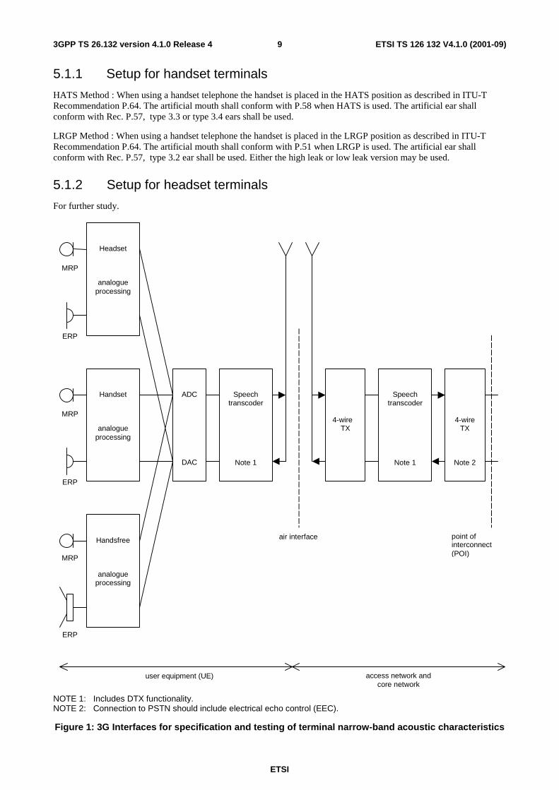
5.1 Test setup for terminals The general access to terminals is described in Figure 1. The preferred acoustic access to 3G terminals is the most realistic simulation of the “average” subscriber. This can be made by using HATS (head and torso simulator) or LRGP (Loudness Rating Guardring Position), with appropriate ear simulation and appropriate mountings for handset terminals in a realistic but reproducible, way to the HATS / LRGP. . Hands-free terminals shall use the HATS or free field microphone techniques in a realistic but reproducible way. Headset measurement methods are for further study, awaiting input from ETSI TC-STQ.
HATS is described in ITU-T Recommendation P.58, appropriate ears are described in ITU-T Recommendation P.57 (type 3.3 and type 3.4 ear), a proper positioning of handsets in realistic conditions is found in ITU-T Recommendation P.64, the test setups for various types of hands-free terminals can be found in ITU-T Recommendation P.581.
LRGP is described in ITU-T Recommendation P.64, appropriate ears are described in ITU-T Recommendation P.57 (type 3.2).
The preferred way of testing is the connection of a terminal to the system simulator with exact defined settings and access points. The test sequences are fed ineither, electrically using a reference codec or using hedirect signal processing approach or acoustically using ITU-T specified devices.
ETSI
ETSI TS 126 132 V4.1.0 (2001-09)93GPP TS 26.132 version 4.1.0 Release 4
5.1.1 Setup for handset terminals
HATS Method : When using a handset telephone the handset is placed in the HATS position as described in ITU-T Recommendation P.64. The artificial mouth shall conform with P.58 when HATS is used. The artificial ear shall conform with Rec. P.57, type 3.3 or type 3.4 ears shall be used.
LRGP Method : When using a handset telephone the handset is placed in the LRGP position as described in ITU-T Recommendation P.64. The artificial mouth shall conform with P.51 when LRGP is used. The artificial ear shall conform with Rec. P.57, type 3.2 ear shall be used. Either the high leak or low leak version may be used.
5.1.2 Setup for headset terminals
For further study.
MRP
ERP
MRP
ERP
MRP
ERP
ADC
DAC
Speechtranscoder
Note 1
Handset
analogueprocessing
Headset
analogueprocessing
Handsfree
analogueprocessing
Speechtranscoder
Note 1
4-wireTX
4-wireTX
Note 2
point ofinterconnect(POI)
air interface
user equipment (UE) access network andcore network
NOTE 1: Includes DTX functionality. NOTE 2: Connection to PSTN should include electrical echo control (EEC).
Figure 1: 3G Interfaces for specification and testing of terminal narrow-band acoustic characteristics
ETSI
ETSI TS 126 132 V4.1.0 (2001-09)103GPP TS 26.132 version 4.1.0 Release 4
5.1.3 Setup for hands-free terminals
5.1.3.1 Vehicle mounted hands-free
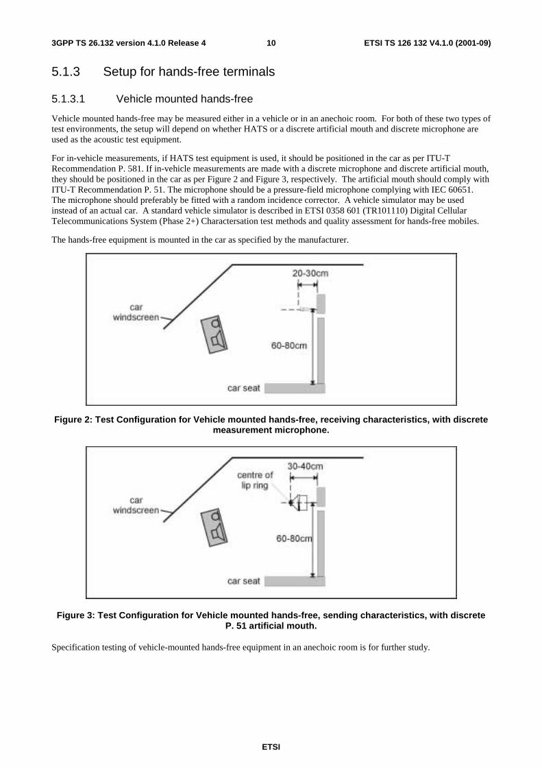
Vehicle mounted hands-free may be measured either in a vehicle or in an anechoic room. For both of these two types of test environments, the setup will depend on whether HATS or a discrete artificial mouth and discrete microphone are used as the acoustic test equipment.
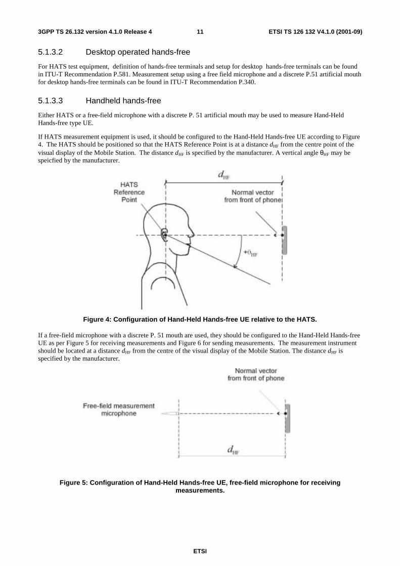
For in-vehicle measurements, if HATS test equipment is used, it should be positioned in the car as per ITU-T Recommendation P. 581. If in-vehicle measurements are made with a discrete microphone and discrete artificial mouth, they should be positioned in the car as per Figure 2 and Figure 3, respectively. The artificial mouth should comply with ITU-T Recommendation P. 51. The microphone should be a pressure-field microphone complying with IEC 60651. The microphone should preferably be fitted with a random incidence corrector. A vehicle simulator may be used instead of an actual car. A standard vehicle simulator is described in ETSI 0358 601 (TR101110) Digital Cellular Telecommunications System (Phase 2+) Charactersation test methods and quality assessment for hands-free mobiles.
The hands-free equipment is mounted in the car as specified by the manufacturer.
Figure 2: Test Configuration for Vehicle mounted hands-free, receiving characteristics, with discrete measurement microphone.
Figure 3: Test Configuration for Vehicle mounted hands-free, sending characteristics, with discrete P. 51 artificial mouth.
Specification testing of vehicle-mounted hands-free equipment in an anechoic room is for further study.
ETSI
ETSI TS 126 132 V4.1.0 (2001-09)113GPP TS 26.132 version 4.1.0 Release 4
5.1.3.2 Desktop operated hands-free
For HATS test equipment, definition of hands-free terminals and setup for desktop hands-free terminals can be found in ITU-T Recommendation P.581. Measurement setup using a free field microphone and a discrete P.51 artificial mouth for desktop hands-free terminals can be found in ITU-T Recommendation P.340.
5.1.3.3 Handheld hands-free
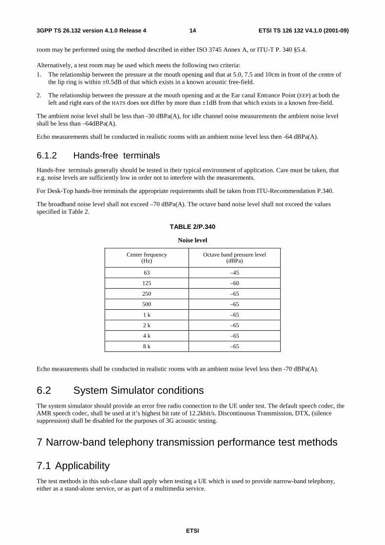
Either HATS or a free-field microphone with a discrete P. 51 artificial mouth may be used to measure Hand-Held Hands-free type UE.
If HATS measurement equipment is used, it should be configured to the Hand-Held Hands-free UE according to Figure 4. The HATS should be positioned so that the HATS Reference Point is at a distance dHF from the centre point of the visual display of the Mobile Station. The distance dHF is specified by the manufacturer. A vertical angle θHF may be speicfied by the manufacturer.
Figure 4: Configuration of Hand-Held Hands-free UE relative to the HATS.
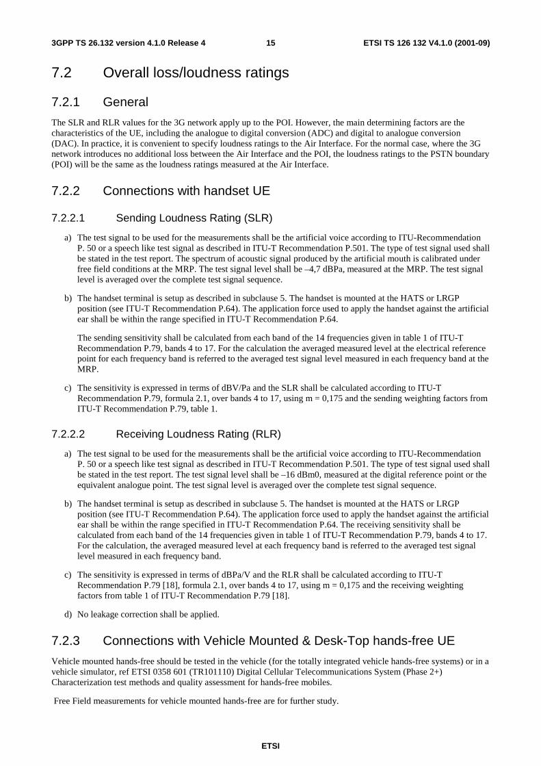
If a free-field microphone with a discrete P. 51 mouth are used, they should be configured to the Hand-Held Hands-free UE as per Figure 5 for receiving measurements and Figure 6 for sending measurements. The measurement instrument should be located at a distance dHF from the centre of the visual display of the Mobile Station. The distance dHF is specified by the manufacturer.
Figure 5: Configuration of Hand-Held Hands-free UE, free-field microphone for receiving measurements.

ETSI
ETSI TS 126 132 V4.1.0 (2001-09)123GPP TS 26.132 version 4.1.0 Release 4
Figure 6: Configuration of Hand-Held Hands-free UE, discrete P. 51 artificial mouth for sending measurements.
5.1.4 Position and calibration of HATS
The horizontal positioning of the HATS reference plane shall be guaranteed within ± 2° for testing hands-free equipment.
The HATS shall be equipped with either Type 3.3 or 3.4 Artificial Ear. For hands-free measurements the HATS shall always be equipped with two artificial ears. The pinnas are specified in Recommendation P.57 for Types 3.3 and 3.4 artificial ears. The pinna shall be positioned on HATS according to ITU-T Recommendation P.58 .
The exact calibration and equalization procedures as well as the combination of the two ear signals for the purpose of measurements can be found in ITU-T Recommendation P.581. For Handheld hands-free UE, the set-up corresponding to 'portable hands-free' in P. 581 should be used.
5.2 Setup of the electrical interfaces
5.2.1 Codec approach and specification
Codec approach: In this approach, a codec is used to convert the companded digital input/output bit-stream of the system simulator to the equivalent analogue values. With this approach a system simulator, simulating the radio link to the terminal under controlled and error free conditions is required. The system simulator has to be equipped with a high-quality codec whose characteristics are as close as possible to ideal.
Definition of 0 dBr point:
D/A converter - a Digital Test Sequence (DTS) representing the codec equivalent of an analogue sinusoidal signal whose rms value is 3.14 dB below the maximum full-load capacity of the codec shall generate 0 dBm across a 600 ohm load;
A/D converter - a 0 dBm signal generated from a 600 ohm source shall give the digital test sequence (DTS) representing the codec equivalent of an analogue sinusoidal signal whose RMS value is 3.14 dB below the maximum full-load capacity of the codec.
Narrow band telephony testing
For testing a 3G terminal supporting narrow-band telephony, the system simulator shall use the AMR speech codec as defined in 3GPP TS 26 series specifications, at the source coding bit rate of 12.2kbit/s. The transcoding from the output of the AMR speech coding in the system simulator to analogue signals shall be carried out using an ITU-T G.711 codec performing to ITU-T G.712 (4-wire analogue).
5.2.2 Direct digital processing approach
In this approach, the companded digital input/output bit-stream of the terminal connected through the radio link to the system simulator is operated upon directly. For the purposes of 3G acoustic testing, the direct digital processing shall use the default speech codec, the AMR speech codec as defined in 3GTS26 series specifications, at it’s highest source coding bit rate of 12.2kbit/s.

ETSI
ETSI TS 126 132 V4.1.0 (2001-09)133GPP TS 26.132 version 4.1.0 Release 4
Narrow band telephony testing
For testing a 3G terminal supporting narrow-band telephony, the system simulator shall use the AMR speech codec as defined in 3GPP TS 26 series specifications, at the source coding bit rate of 12.2kbit/s.
5.3 Accuracy of test equipment
Unless specified otherwise, the accuracy of measurements made by test equipment shall be better than:
Item Accuracy Electrical Signal Power Electrical Signal Power Sound pressure Time Frequency
±0,2 dB for levels ≥ -50 dBm ±0,4 dB for levels < -50 dBm ±0,7 dB ±5 % ±0,2 %
Unless specified otherwise, the accuracy of the signals generated by the test equipment shall be better than:
Quantity Accuracy Sound pressure level at MRP Electrical excitation levels Frequency generation
±1 dB for 200 Hz to 4 kHz ±3 dB for 100 Hz to 200 Hz and 4 kHz to 8 kHz ±0,4 dB (see note 1) ±2 % (see note 2)
NOTE 1: Across the whole frequency range. NOTE 2: When measuring sampled systems, it is advisable to avoid measuring at sub-
multiples of the sampling frequency. There is a tolerance of ±2 % on the generated frequencies, which may be used to avoid this problem, except for 4 kHz where only the -2 % tolerance may be used.
The measurements results shall be corrected for the measured deviations from the nominal level.
The sound level measurement equipment shall conform to IEC 651 Type 1.
5.4 Test signals Due to the coding of the speech signals, standard sinusoidal test signals are not applicable for 3G acoustic tests, appropriate test signals (general description) are defined in ITU-T Recommendation P.50 and P.501. More information can be found in the test procedures described below.
For testing the narrow-band telephony service provided by a terminal the test signal used shall be band limited between 100 Hz and 4 kHz with a bandpass filter providing a minimum of 24 dB/Oct. filter roll off, when feeding into the receiving direction.
The test signal levels are referred to the average level of the (band limited in receiving direction) test signal, averaged over the complete test sequence . unless specified otherwise.
6 Test conditions
6.1 Environmental conditions
6.1.1 Handset and headset terminals
The environmental conditions for testing handset and headset UE is specified in §6.1.1 TS 26.132, as follows:
For handset and headset measurements the test room shall be practically free-field down to a lowest frequency of 275 Hz, the handset or the headset including the HATS / LRGP shall lie totally within this free-field volume. This shall be met if deviations of the ideal free-field conditions are less than +/- 1 dB. Qualification of the test
ETSI
ETSI TS 126 132 V4.1.0 (2001-09)143GPP TS 26.132 version 4.1.0 Release 4
room may be performed using the method described in either ISO 3745 Annex A, or ITU-T P. 340 §5.4. Alternatively, a test room may be used which meets the following two criteria:
1. The relationship between the pressure at the mouth opening and that at 5.0, 7.5 and 10cm in front of the centre of the lip ring is within ±0.5dB of that which exists in a known acoustic free-field.
2. The relationship between the pressure at the mouth opening and at the Ear canal Entrance Point (EEP) at both the left and right ears of the HATS does not differ by more than ±1dB from that which exists in a known free-field.
The ambient noise level shall be less than -30 dBPa(A), for idle channel noise measurements the ambient noise level shall be less than –64dBPa(A).
Echo measurements shall be conducted in realistic rooms with an ambient noise level less then -64 dBPa(A).
6.1.2 Hands-free terminals
Hands-free terminals generally should be tested in their typical environment of application. Care must be taken, that e.g. noise levels are sufficiently low in order not to interfere with the measurements.
For Desk-Top hands-free terminals the appropriate requirements shall be taken from ITU-Recommendation P.340.
The broadband noise level shall not exceed –70 dBPa(A). The octave band noise level shall not exceed the values specified in Table 2.
TABLE 2/P.340
Noise level
Echo measurements shall be conducted in realistic rooms with an ambient noise level less then -70 dBPa(A).
6.2 System Simulator conditions The system simulator should provide an error free radio connection to the UE under test. The default speech codec, the AMR speech codec, shall be used at it’s highest bit rate of 12.2kbit/s. Discontinuous Transmission, DTX, (silence suppression) shall be disabled for the purposes of 3G acoustic testing.
7 Narrow-band telephony transmission performance test methods
7.1 Applicability The test methods in this sub-clause shall apply when testing a UE which is used to provide narrow-band telephony, either as a stand-alone service, or as part of a multimedia service.
Center frequency (Hz)
Octave band pressure level (dBPa)
63 –45
125 –60
250 –65
500 –65
1 k –65
2 k –65
4 k –65
8 k –65
ETSI
ETSI TS 126 132 V4.1.0 (2001-09)153GPP TS 26.132 version 4.1.0 Release 4
7.2 Overall loss/loudness ratings
7.2.1 General
The SLR and RLR values for the 3G network apply up to the POI. However, the main determining factors are the characteristics of the UE, including the analogue to digital conversion (ADC) and digital to analogue conversion (DAC). In practice, it is convenient to specify loudness ratings to the Air Interface. For the normal case, where the 3G network introduces no additional loss between the Air Interface and the POI, the loudness ratings to the PSTN boundary (POI) will be the same as the loudness ratings measured at the Air Interface.
7.2.2 Connections with handset UE
7.2.2.1 Sending Loudness Rating (SLR)
a) The test signal to be used for the measurements shall be the artificial voice according to ITU-Recommendation P. 50 or a speech like test signal as described in ITU-T Recommendation P.501. The type of test signal used shall be stated in the test report. The spectrum of acoustic signal produced by the artificial mouth is calibrated under free field conditions at the MRP. The test signal level shall be –4,7 dBPa, measured at the MRP. The test signal level is averaged over the complete test signal sequence.
b) The handset terminal is setup as described in subclause 5. The handset is mounted at the HATS or LRGP position (see ITU-T Recommendation P.64). The application force used to apply the handset against the artificial ear shall be within the range specified in ITU-T Recommendation P.64.
The sending sensitivity shall be calculated from each band of the 14 frequencies given in table 1 of ITU-T Recommendation P.79, bands 4 to 17. For the calculation the averaged measured level at the electrical reference point for each frequency band is referred to the averaged test signal level measured in each frequency band at the MRP.
c) The sensitivity is expressed in terms of dBV/Pa and the SLR shall be calculated according to ITU-T Recommendation P.79, formula 2.1, over bands 4 to 17, using m = 0,175 and the sending weighting factors from ITU-T Recommendation P.79, table 1.
7.2.2.2 Receiving Loudness Rating (RLR)
a) The test signal to be used for the measurements shall be the artificial voice according to ITU-Recommendation P. 50 or a speech like test signal as described in ITU-T Recommendation P.501. The type of test signal used shall be stated in the test report. The test signal level shall be –16 dBm0, measured at the digital reference point or the equivalent analogue point. The test signal level is averaged over the complete test signal sequence.
b) The handset terminal is setup as described in subclause 5. The handset is mounted at the HATS or LRGP position (see ITU-T Recommendation P.64). The application force used to apply the handset against the artificial ear shall be within the range specified in ITU-T Recommendation P.64. The receiving sensitivity shall be calculated from each band of the 14 frequencies given in table 1 of ITU-T Recommendation P.79, bands 4 to 17. For the calculation, the averaged measured level at each frequency band is referred to the averaged test signal level measured in each frequency band.
c) The sensitivity is expressed in terms of dBPa/V and the RLR shall be calculated according to ITU-T Recommendation P.79 [18], formula 2.1, over bands 4 to 17, using m = 0,175 and the receiving weighting factors from table 1 of ITU-T Recommendation P.79 [18].
d) No leakage correction shall be applied.
7.2.3 Connections with Vehicle Mounted & Desk-Top hands-free UE
Vehicle mounted hands-free should be tested in the vehicle (for the totally integrated vehicle hands-free systems) or in a vehicle simulator, ref ETSI 0358 601 (TR101110) Digital Cellular Telecommunications System (Phase 2+) Characterization test methods and quality assessment for hands-free mobiles.
Free Field measurements for vehicle mounted hands-free are for further study.
ETSI
ETSI TS 126 132 V4.1.0 (2001-09)163GPP TS 26.132 version 4.1.0 Release 4
7.2.3.1 Sending Loudness Rating (SLR)
a) The test signal to be used for the measurements shall be the artificial voice according to ITU-Recommendation P. 50 or a speech like test signal as described in ITU-T Recommendation P.501. The type of test signal used shall be stated in the test report. The spectrum of acoustic signal produced by the artificial mouth is calibrated under free field conditions at the MRP. The test signal level shall be –4,7 dBPa, measured at the MRP. The test signal level is averaged over the complete test signal sequence. The broadband signal level then is adjusted to –28.7 dBPa at the HFRP or the HATSHFRP (as defined in P. 581) and the spectrum is not altered.
The spectrum at the MRP and the actual level at the MRP (measured in third octaves) is used as reference to determine the sending sensitivity SmJ.
b) The hands-free terminal is setup as described in subclause 5. The sending sensitivity shall be calculated from each band of the 14 frequencies given in table 1 of ITU-T Recommendation P.79 , bands 4 to 17. For the calculation the averaged measured level at the electrical reference point for each frequency band is referred to the averaged test signal level measured in each frequency band at the MRP.
c) The sensitivity is expressed in terms of dBV/Pa and the SLR shall be calculated according to ITU-T Recommendation P.79, formula 2.1, over bands 4 to 17, using m = 0,175 and the sending weighting factors from ITU-T Recommendation P.79, table 1.
7.2.3.2 Receiving Loudness Rating (RLR)
a) The test signal to be used for the measurements shall be the artificial voice according to ITU-Recommendation P. 50 or a speech like test signal as described in ITU-T Recommendation P.501. The type of test signal used shall be stated in the test report. The test signal level shall be –16 dBm0, measured at the digital reference point or the equivalent analogue point. The test signal level is averaged over the complete test signal sequence.
b) The hands-free terminal is setup as described in subclause 5. If HATS is used then it is freefield equalized as described in ITU-T Recommendation P.581. The equalized output signal of each artificial ear is power-averaged on the total time of analysis; the “right ” and “left” signals are voltage-summed for each 1/3 octave band frequency band; these 1/3 octave band data are considered as the input signal to be used for calculations or measurements. The receiving sensitivity shall be calculated from each band of the 14 frequencies given in table 1 of ITU-T Recommendation P.79 , bands 4 to 17.
For the calculation the averaged measured level at each frequency band is referred to the averaged test signal level measured in each frequency band.
c) The sensitivity is expressed in terms of dBPa/V and the RLR shall be calculated according to ITU-T Recommendation P.79 [18], formula 2.1, over bands 4 to 17, using m = 0,175 and the receiving weighting factors from table 1 of ITU-T Recommendation P.79.
d) No leakage correction shall be applied. The hands-free correction as described in P.340 shall be applied. To compute Receiving loudness rating (RLR) for hands-free terminal (see also ITU-T Recommendation P.340 ), when using the combination of left and right ear signals from HATS the HFLE has to be 8 dB, instead of 14 dB. For further information see ITU-T Recommendation P.581.
7.2.4 Connections with Handheld hands-free UE
7.2.4.1 Sending Loudness Rating (SLR)
a) The test signal to be used for the measurements shall be the artificial voice according to ITU-Recommendation P. 50 or a speech like test signal as described in ITU-T Recommendation P.501. The type of test signal used shall be stated in the test report. The spectrum of acoustic signal produced by the artificial mouth is calibrated under free field conditions at the MRP. The test signal level shall be –4,7 dBPa, measured at the MRP. The test signal level is averaged over the complete test signal sequence. The broadband signal level then is adjusted to –28.7 dBPa at the HFRP or the HATSHFRP (as defined in P. 581) and the spectrum is not altered.
The spectrum at the MRP and the actual level at the MRP (measured in third octaves) is used as reference to determine the sending sensitivity SmJ.

ETSI
ETSI TS 126 132 V4.1.0 (2001-09)173GPP TS 26.132 version 4.1.0 Release 4
b) The hands-free terminal is setup as described in subclause 5.1.3.3. The sending sensitivity shall be calculated from each band of the 14 frequencies given in table 1 of ITU-T Recommendation P.79, bands 4 to 17. For the calculation the averaged measured level at the electrical reference point foreach frequency band is referred to the averaged test signal level measured in each frequency band at the MRP.
c) The sensitivity is expressed in terms of dBV/Pa and the SLR shall be calculated according to ITU-T Recommendation P.79, formula 2.1, over bands 4 to 17, using m = 0,175 and the sending weighting factors from ITU-T Recommendation P.79, table 1.
7.2.4.2 Receiving Loudness Rating (RLR)
a) The test signal to be used for the measurements shall be the artificial voice according to ITU-Recommendation P. 50 or a speech like test signal as described in ITU-T Recommendation P.501. The type of test signal used shall be stated in the test report. The test signal level shall be –16 dBm0, measured at the digital reference point or the equivalent analogue point. The test signal level is averaged over the complete test signal sequence.
b) The hands-free terminal is setup as described in subclause 5.1.3.3. If HATS is used then it is freefield equalized as described in ITU-T Recommendation P.581. The equalized output signal of each artificial ear is power-averaged on the total time of analysis; the “right ” and “left” signals are voltage-summed for each 1/3 octave band frequency band; these 1/3 octave band data are considered as the input signal to be used for calculations or measurements. The receiving sensitivity shall be calculated from each band of the 14 frequencies given in table 1 of ITU-T Recommendation P.79 , bands 4 to 17.
For the calculation the averaged measured level at each frequency band is referred to the averaged test signal level measured in each frequency band.
c) The sensitivity is expressed in terms of dBPa/V and the RLR shall be calculated according to ITU-T Recommendation P.79 [18], formula 2.1, over bands 4 to 17, using m = 0,175 and the receiving weighting factors from table 1 of ITU-T Recommendation P.79.
d) No leakage correction shall be applied. The hands-free correction as described in P.340 shall be applied. To compute the Receiving loudness rating (RLR) for hands-free terminals (see also ITU-T Recommendation P.340) when using the combination of left and right ear signals from HATS the HFLE has to be 8 dB, instead of 14 dB. For further information see ITU-T Recommendation P.581.
7.2.5 Connections with headset UE
For Further study
7.3 Idle channel noise (handset and headset UE)
7.3.1 Sending
The terminal should be configured to the test equipment as described in subclause 5.1.
The environment shall comply with the conditions described in subclause 6.1 for idle channel noise measurement.
The Psophometric noise level at the output of the SS is measured. The psophometric filter is described in ITU-T Recommendation O.41.
A test signal may have to be intermittently applied to prevent ‘silent mode’ operation of the MS. This is for further study.
7.3.2 Receiving
The terminal should be configured to the test equipment as described in subclause 5.1.
The environment shall comply with the conditions described in subclause 6.1.
A test signal may have to be intermittently applied to prevent ‘silent mode’ operation of the MS. This is for further study.

ETSI
ETSI TS 126 132 V4.1.0 (2001-09)183GPP TS 26.132 version 4.1.0 Release 4
The A-weighted level of the noise shall be measured at the ERP. The A-weighting filter is descried IEC 60651 [12].
7.4 Sensitivity/frequency characteristics
7.4.1 Handset UE sending
a) The test signal to be used for the measurements shall be the artificial voice according to ITU-Recommendation P. 50 or a speech like test signal as described in ITU-T Recommendation P.501. The type of test signal used shall be stated in the test report. The spectrum of acoustic signal produced by the artificial mouth is calibrated under free field conditions at the MRP. The test signal level shall be –4,7 dBPa, measured at the MRP. The test signal level is averaged over the complete test signal sequence.
b) The handset terminal is setup as described in subclause 5. The handset is mounted at the HATS / LRGP position (see ITU-T Recommendation P.64). The application force used to apply the handset against the artificial ear shall be within the range specified in ITU-T Recommendation P.64.
Measurements shall be made at one twelfth-octave intervals as given by the R.40 series of preferred numbers in ISO 3 [17] for frequencies from 100 Hz to 4 kHz inclusive. For the calculation the averaged measured level at the electrical reference point for each frequency band is referred to the averaged test signal level measured in each frequency band at the MRP.
c) The sensitivity is expressed in terms of dBV/Pa.
7.4.2 Handset UE receiving
a) The test signal to be used for the measurements shall be the artificial voice according to ITU-Recommendation P. 50 or a speech like test signal as described in ITU-T Recommendation P.501. The type of test signal used shall be stated in the test report. The test signal level shall be –16 dBm0, measured at the digital reference point or the equivalent analogue point. The test signal level is averaged over the complete test signal sequence.
b) The handset terminal is setup as described in subclause 5. The handset is mounted at the HATS / LRGP position (see ITU-T Recommendation P.64). The application force used to apply the handset against the artificial ear shall be within the range specified in ITU-T Recommendation P.64.
Measurements shall be made at one twelfth-octave intervals as given by the R.40 series of preferred numbers in ISO 3 [17] for frequencies from 100 Hz to 4 kHz inclusive. For the calculation the averaged measured level at each frequency band is referred to the averaged test signal level measured in each frequency band.
c) The sensitivity is expressed in terms of dBPa/V, referred to the ERP. Information about correction factors are available in ITU-T Recommendation P.57.
7.4.3 Vehicle Mounted & Desk-Top hands-free UE sending
a) The test signal to be used for the measurements shall be the artificial voice according to ITU-Recommendation P. 50 or a speech like test signal as described in ITU-T Recommendation P.501. The type of test signal used shall be stated in the test report. The spectrum of acoustic signal produced by the artificial mouth is calibrated under free field conditions at the MRP. The test signal level shall be –4,7 dBPa, measured at the MRP. The test signal level is averaged over the complete test signal sequence. The broadband signal level then is adjusted to –28.7 dBPa at the HFRP or the HATSHFRP (as defined in P. 581) and the spectrum is not altered.
The spectrum at the MRP and the actual level at the MRP (measured in third octaves) is used as reference to determine the sending sensitivity SmJ.
b) The hands-free terminal is setup as described in subclause 5. Measurements shall be made at one third-octave intervals as given by the R.40 series of preferred numbers in ISO 3 [17] for frequencies from 100 Hz to 4 kHz inclusive. For the calculation the averaged measured level at each frequency band is referred to the averaged test signal level measured in each frequency band.
c) The sensitivity is expressed in terms of dBV/Pa.
ETSI
ETSI TS 126 132 V4.1.0 (2001-09)193GPP TS 26.132 version 4.1.0 Release 4
7.4.4 Vehicle Mounted & Desk-Top hands-free UE receiving
a) The test signal to be used for the measurements shall be the artificial voice according to ITU-Recommendation P. 50 or a speech like test signal as described in ITU-T Recommendation P.501. The type of test signal used shall be stated in the test report. The test signal level shall be –16 dBm0, measured at the digital reference point or the equivalent analogue point. The test signal level is averaged over the complete test signal sequence.
b) The hands-free terminal is setup as described in subclause 5. If the HATS is used then it is freefield equalized as described in ITU-T Recommendation P.581. The equalized output signal of each artificial ear is power-averaged on the total time of analysis; the “right ” and “left” signals are voltage-summed for each 1/3 octave band frequency band; these 1/3 octave band data are considered as the input signal to be used for calculations or measurements. Measurements shall be made at one third-octave intervals as given by the R.40 series of preferred numbers in ISO 3 [17] for frequencies from 100 Hz to 4 kHz inclusive. For the calculation the averaged measured level at each frequency band is referred to the averaged test signal level measured in each frequency band.
c) The sensitivity is expressed in terms of dBPa/V.
7.4.5 Hand-Held hands-free UE sending
a) The test signal to be used for the measurements shall be the artificial voice according to ITU-Recommendation P. 50 or a speech like test signal as described in ITU-T Recommendation P.501. The type of test signal used shall be stated in the test report. The spectrum of acoustic signal produced by the artificial mouth is calibrated under free field conditions at the MRP. The test signal level shall be –4,7 dBPa, measured at the MRP. The test signal level is averaged over the complete test signal sequence. The broadband signal level then is adjusted to –28.7 dBPa at the HFRP or the HATSHFRP (as defined in P. 581) and the spectrum is not altered.
The spectrum at the MRP and the actual level at the MRP (measured in third octaves) is used as reference to determine the sending sensitivity SmJ.
b) The hands-free terminal is setup as described in subclause 5.1.3.3. Measurements shall be made at one third-octave intervals as given by the R.40 series of preferred numbers in ISO 3 [17] for frequencies from 100 Hz to 4 kHz inclusive. For the calculation the averaged measured level at each frequency band is referred to the averaged test signal level measured in each frequency band.
c) The sensitivity is expressed in terms of dBV/Pa.
7.4.6 Hand-Held hands-free UE receiving
a) The test signal to be used for the measurements shall be the artificial voice according to ITU-Recommendation P. 50 or a speech like test signal as described in ITU-T Recommendation P.501. The type of test signal used shall be stated in the test report. The test signal level shall be –16 dBm0, measured at the digital reference point or the equivalent analogue point. The test signal level is averaged over the complete test signal sequence.
b) The hands-free terminal is setup as described in subclause 5.1.3.3. If the HATS is used then it is freefield equalized as described in ITU-T Recommendation P.581. The equalized output signal of each artificial ear is power-averaged on the total time of analysis; the “right ” and “left” signals are voltage-summed for each 1/3 octave band frequency band; these 1/3 octave band data are considered as the input signal to be used for calculations or measurements. Measurements shall be made at one third-octave intervals as given by the R.40 series of preferred numbers in ISO 3 [17] for frequencies from 100 Hz to 4 kHz inclusive. For the calculation the averaged measured level at each frequency band is referred to the averaged test signal level measured in each frequency band.
c) The sensitivity is expressed in terms of dBPa/V.

ETSI
ETSI TS 126 132 V4.1.0 (2001-09)203GPP TS 26.132 version 4.1.0 Release 4
7.5 Sidetone characteristics
7.5.1 Connections with Handset UE
The test signal to be used for the measurements shall be the artificial voice according to ITU-Recommendation P. 50 or a speech like test signal as described in ITU-T Recommendation P.501. The type of test signal used shall be stated in the test report. The spectrum of the acoustic signal produced by the artificial mouth is calibrated under free field conditions at the MRP. The test signal level shall be –4,7 dBPa, measured at the MRP. The test signal level is averaged over the complete test signal sequence.
The handset shall be positioned in the LRGP. The handset terminal is setup as described in subclause 5, with the following exception: The Type 3.2 Low Leak artificial ear, according to ITU-T Recommendation P. 57 shall be used.
The possible use of Type 3.2 High Leak, Type 3.3, or Type 3.4 artificial ears for measurement of the sidetone loss is for further study.
The sidetone path loss LmeST as expressed in dB shall be calculated from each band of the 14 frequencies given in table 1 of ITU-T Recommendation P.79, bands 4 to 17. The STMR (in dB) shall be calculated from the formula 2.1 of ITU-T Recommendation P.79, using m = 0,225 and the weighting factors in table 3 of ITU-T Recommendation P.79.
7.5.2 Headset UE
The test signal to be used for the measurements shall be the artificial voice according to ITU-Recommendation P. 50 or a speech like test signal as described in ITU-T Recommendation P.501. The type of test signal used shall be stated in the test report. The spectrum of the acoustic signal produced by the artificial mouth is calibrated under free field conditions at the MRP. The test signal level shall be –4,7 dBPa, measured at the MRP. The test signal level is averaged over the complete test signal sequence.
The artificial ear type is for further study.
The sidetone path loss LmeST as expressed in dB shall be calculated from each band of the 14 frequencies given in table 1 of ITU-T Recommendation P.79, bands 4 to 17. The STMR (in dB) shall be calculated from the formula B-4 of ITU-T Recommendation P.79 [16], using m = 0,225 and the weighting factors in Table 3 of ITU-T Recommendation P.79 [16].
7.5.3 Hands-free UE (all categories)
No requirement for other than echo control.
7.6 Stability loss Where a user controlled volume control is provided it is set to maximum.Handset UE: The handset is placed on a hard plane surface with the transducers facing the surface.
Headset UE: for further study
Hands-free UE (all categories): no requirement other than echo loss.
A gain equivalent to the minimum stability margin is inserted in the loop between the go and return paths of the reference speech coder in the SS and any acoustic echo control is enabled.
A test signal according to ITU-T O.131 is injected into the loop at the analogue or digital input of the reference speech codec of the SS and the stability is measured. The test signal has a level of -10 dBm0 and a duration of 1 s.
No continuous audible oscillation shall be detected after the test signal is switched off.
ETSI
ETSI TS 126 132 V4.1.0 (2001-09)213GPP TS 26.132 version 4.1.0 Release 4
7.7 Acoustic echo control
7.7.1 General
The echo loss (EL) presented by the 3G network at the POI should be at least 46 dB during single talk. This value takes into account the fact that UE is likely to be used in a wide range of noise environments.
7.7.2 Acoustic echo control in a Hands-free UE
TCLw:
The hands-free is setup in a room where it is intended to be used, eg. for an office type hands-free UE a typical “office-type” room should be used; a vehicle-mounted hands-free UE should be tested in a vehicle or vehicle simulator, as specified by the UE manufacturer. [For reference on a suitable vehicle simulator see ETSI 0358 601 (TR101110) Digital Cellular Telecommunications System (Phase 2+) .] The ambient noise level shall be less than -70 dBPa(A). The attenuation from reference point input to reference point output shall be measured using a speech like test signal .
Before the actual test a training sequence consisting of 10 s artificial voice male and 10 s artificial voice female according to ITU-T Recommendation P.50 is altered.
Either a logarithmically spaced multi-sine or PN-sequence test signal shall be used.
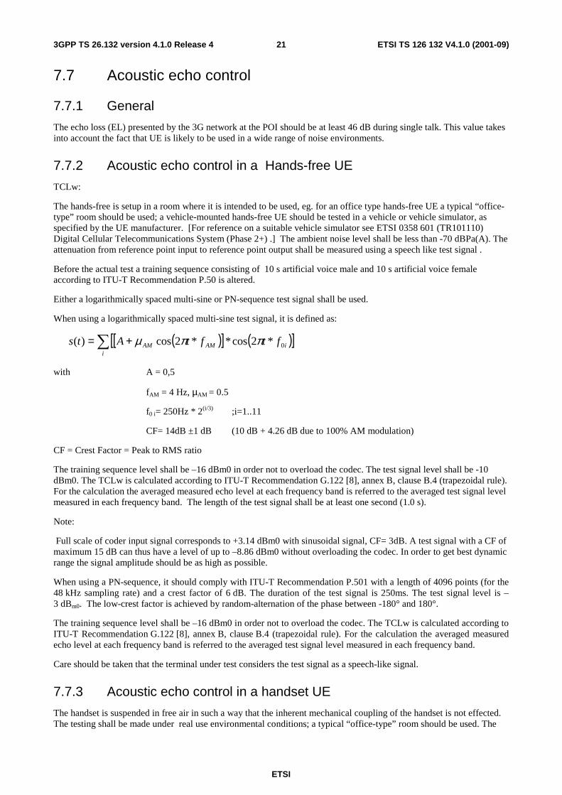
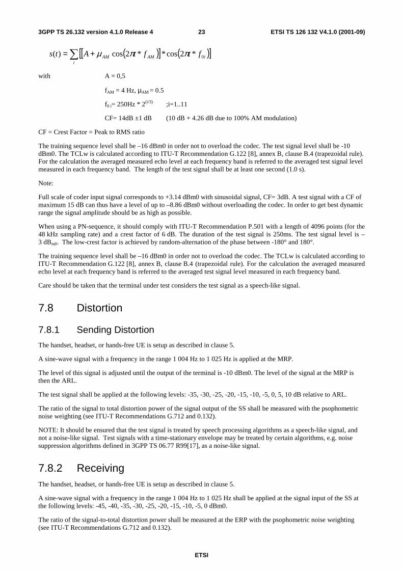
When using a logarithmically spaced multi-sine test signal, it is defined as:
( )[ ] ( )[ ]∑ +=i
iAMAM ftftAts 0*2cos**2cos)( ππµ
with A = 0,5
fAM = 4 Hz, µAM = 0.5
f0 i= 250Hz * 2(i/3) ;i=1..11
CF= 14dB ±1 dB (10 dB + 4.26 dB due to 100% AM modulation)
CF = Crest Factor = Peak to RMS ratio
The training sequence level shall be –16 dBm0 in order not to overload the codec. The test signal level shall be -10 dBm0. The TCLw is calculated according to ITU-T Recommendation G.122 [8], annex B, clause B.4 (trapezoidal rule). For the calculation the averaged measured echo level at each frequency band is referred to the averaged test signal level measured in each frequency band. The length of the test signal shall be at least one second (1.0 s).
Note:
Full scale of coder input signal corresponds to +3.14 dBm0 with sinusoidal signal, CF= 3dB. A test signal with a CF of maximum 15 dB can thus have a level of up to –8.86 dBm0 without overloading the codec. In order to get best dynamic range the signal amplitude should be as high as possible.
When using a PN-sequence, it should comply with ITU-T Recommendation P.501 with a length of 4096 points (for the 48 kHz sampling rate) and a crest factor of 6 dB. The duration of the test signal is 250ms. The test signal level is –3 dBm0. The low-crest factor is achieved by random-alternation of the phase between -180° and 180°.
The training sequence level shall be –16 dBm0 in order not to overload the codec. The TCLw is calculated according to ITU-T Recommendation G.122 [8], annex B, clause B.4 (trapezoidal rule). For the calculation the averaged measured echo level at each frequency band is referred to the averaged test signal level measured in each frequency band.
Care should be taken that the terminal under test considers the test signal as a speech-like signal.
7.7.3 Acoustic echo control in a handset UE
The handset is suspended in free air in such a way that the inherent mechanical coupling of the handset is not effected. The testing shall be made under real use environmental conditions; a typical “office-type” room should be used. The
ETSI
ETSI TS 126 132 V4.1.0 (2001-09)223GPP TS 26.132 version 4.1.0 Release 4
ambient noise level shall be less than -64 dBPa(A). The attenuation from reference point input to reference point output shall be measured using the speech like test signal defined below.
Before the actual test a training sequence consisting of 10 s artificial voice male and 10 s artificial voice female according to ITU-T Recommendation P.50 is altered.
Either a logarithmically spaced multi-sine or PN-sequency test signal shall be used.
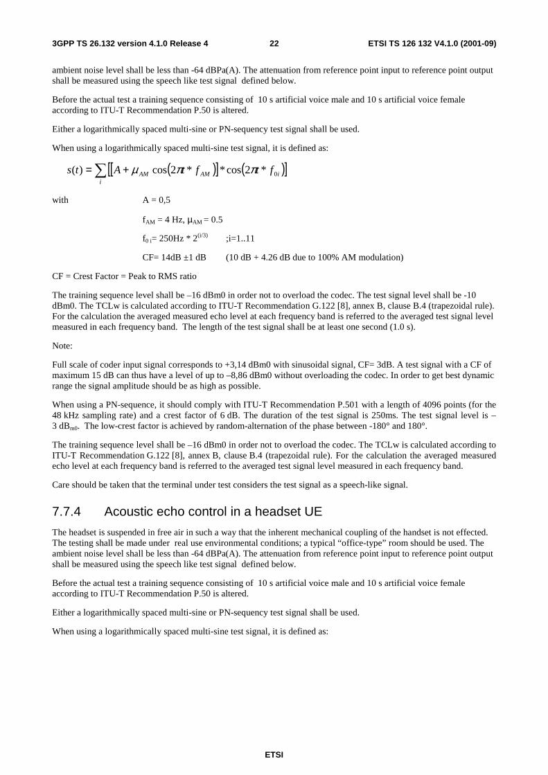
When using a logarithmically spaced multi-sine test signal, it is defined as:
( )[ ] ( )[ ]∑ +=i
iAMAM ftftAts 0*2cos**2cos)( ππµ
with A = 0,5
fAM = 4 Hz, µAM = 0.5
f0 i= 250Hz * 2(i/3) ;i=1..11
CF= 14dB ±1 dB (10 dB + 4.26 dB due to 100% AM modulation)
CF = Crest Factor = Peak to RMS ratio
The training sequence level shall be –16 dBm0 in order not to overload the codec. The test signal level shall be -10 dBm0. The TCLw is calculated according to ITU-T Recommendation G.122 [8], annex B, clause B.4 (trapezoidal rule). For the calculation the averaged measured echo level at each frequency band is referred to the averaged test signal level measured in each frequency band. The length of the test signal shall be at least one second (1.0 s).
Note:
Full scale of coder input signal corresponds to +3,14 dBm0 with sinusoidal signal, CF= 3dB. A test signal with a CF of maximum 15 dB can thus have a level of up to –8,86 dBm0 without overloading the codec. In order to get best dynamic range the signal amplitude should be as high as possible.
When using a PN-sequence, it should comply with ITU-T Recommendation P.501 with a length of 4096 points (for the 48 kHz sampling rate) and a crest factor of 6 dB. The duration of the test signal is 250ms. The test signal level is –3 dBm0. The low-crest factor is achieved by random-alternation of the phase between -180° and 180°.
The training sequence level shall be –16 dBm0 in order not to overload the codec. The TCLw is calculated according to ITU-T Recommendation G.122 [8], annex B, clause B.4 (trapezoidal rule). For the calculation the averaged measured echo level at each frequency band is referred to the averaged test signal level measured in each frequency band.
Care should be taken that the terminal under test considers the test signal as a speech-like signal.
7.7.4 Acoustic echo control in a headset UE
The headset is suspended in free air in such a way that the inherent mechanical coupling of the handset is not effected. The testing shall be made under real use environmental conditions; a typical “office-type” room should be used. The ambient noise level shall be less than -64 dBPa(A). The attenuation from reference point input to reference point output shall be measured using the speech like test signal defined below.
Before the actual test a training sequence consisting of 10 s artificial voice male and 10 s artificial voice female according to ITU-T Recommendation P.50 is altered.
Either a logarithmically spaced multi-sine or PN-sequency test signal shall be used.
When using a logarithmically spaced multi-sine test signal, it is defined as:
ETSI
ETSI TS 126 132 V4.1.0 (2001-09)233GPP TS 26.132 version 4.1.0 Release 4
( )[ ] ( )[ ]∑ +=i
iAMAM ftftAts 0*2cos**2cos)( ππµ
with A = 0,5
fAM = 4 Hz, µAM = 0.5
f0 i= 250Hz * 2(i/3) ;i=1..11
CF= 14dB ±1 dB (10 dB + 4.26 dB due to 100% AM modulation)
CF = Crest Factor = Peak to RMS ratio
The training sequence level shall be –16 dBm0 in order not to overload the codec. The test signal level shall be -10 dBm0. The TCLw is calculated according to ITU-T Recommendation G.122 [8], annex B, clause B.4 (trapezoidal rule). For the calculation the averaged measured echo level at each frequency band is referred to the averaged test signal level measured in each frequency band. The length of the test signal shall be at least one second (1.0 s).
Note:
Full scale of coder input signal corresponds to +3.14 dBm0 with sinusoidal signal, CF= 3dB. A test signal with a CF of maximum 15 dB can thus have a level of up to –8.86 dBm0 without overloading the codec. In order to get best dynamic range the signal amplitude should be as high as possible.
When using a PN-sequence, it should comply with ITU-T Recommendation P.501 with a length of 4096 points (for the 48 kHz sampling rate) and a crest factor of 6 dB. The duration of the test signal is 250ms. The test signal level is –3 dBm0. The low-crest factor is achieved by random-alternation of the phase between -180° and 180°.
The training sequence level shall be –16 dBm0 in order not to overload the codec. The TCLw is calculated according to ITU-T Recommendation G.122 [8], annex B, clause B.4 (trapezoidal rule). For the calculation the averaged measured echo level at each frequency band is referred to the averaged test signal level measured in each frequency band.
Care should be taken that the terminal under test considers the test signal as a speech-like signal.
7.8 Distortion
7.8.1 Sending Distortion
The handset, headset, or hands-free UE is setup as described in clause 5.
A sine-wave signal with a frequency in the range 1 004 Hz to 1 025 Hz is applied at the MRP.
The level of this signal is adjusted until the output of the terminal is -10 dBm0. The level of the signal at the MRP is then the ARL.
The test signal shall be applied at the following levels: -35, -30, -25, -20, -15, -10, -5, 0, 5, 10 dB relative to ARL.
The ratio of the signal to total distortion power of the signal output of the SS shall be measured with the psophometric noise weighting (see ITU-T Recommendations G.712 and 0.132).
NOTE: It should be ensured that the test signal is treated by speech processing algorithms as a speech-like signal, and not a noise-like signal. Test signals with a time-stationary envelope may be treated by certain algorithms, e.g. noise suppression algorithms defined in 3GPP TS 06.77 R99[17], as a noise-like signal.
7.8.2 Receiving The handset, headset, or hands-free UE is setup as described in clause 5.
A sine-wave signal with a frequency in the range 1 004 Hz to 1 025 Hz shall be applied at the signal input of the SS at the following levels: -45, -40, -35, -30, -25, -20, -15, -10, -5, 0 dBm0.
The ratio of the signal-to-total distortion power shall be measured at the ERP with the psophometric noise weighting (see ITU-T Recommendations G.712 and 0.132).
ETSI
ETSI TS 126 132 V4.1.0 (2001-09)243GPP TS 26.132 version 4.1.0 Release 4
NOTE: It should be ensured that the test signal is treated by speech processing algorithms as a speech-like signal, and not a noise-like signal. Test signals with a time-stationary envelope may be treated by certain algorithms, e.g. noise suppression algorithms defined in 3GPP TS 06.77 R99[17], as a noise-like signal.
7.9 Ambient Noise Rejection Handset and Headset UE:
Note: This section applies to terminals providing narrow- and wide-band telephony. However, the procedure for measuring ambient noise rejection is defined only over narrow-band frequency range. Thus the test method for ambient noise rejection is the same for either narrow- or wide-band telephony.
a) A 1/2 inch pressure microphone is calibrated using a known sound source and mounted at the MRP, without the LRGP or HATS present. A frequency analyser is calibrated to enable the sound pressure levels at the microphone to be determined in 1/3rd Octave bands.
b) Flood the room in which the measurement is to be made with a band limited (100 Hz to 8 kHz) pink noise to within ±3 dB. The level at MRP shall be adjusted to 70 dB(A) (-24 dBPa(A)). The tolerance on this level is +/-1 dB. The resulting sound spectrum is Prn dBPa, measured in 1/3rd Octave bands.
To ensure that the sound field is diffuse enough, the following apply:
The diffuse sound field is calibrated in the absence of any local obstacles. The averaged field shall be uniform to within +/- 3 dB within a radius of 0,15 m of the MRP, when measured in one-third octave bands from 100 Hz to 3,15 kHz.
NOTE 1: The pressure intensity index, as defined in ISO 9614, may prove to be a suitable method for assessing the diffuse field.
NOTE 2: Where more than one loudspeaker is used to produce the desired sound field, the loudspeakers must be fed with non-coherent electrical signals to eliminate standing waves and other interference effects.
c) Position the HATS or LRGP test head in the correct relative position to the MRP and mount the MS under test, according to clause 5.1.1. Recalibrate the 1/3rd Octave frequency analyser using a known voltage source to facilitate the analysis of the voltage Vrn, where Vrn is the voltage at the audio output of the SS due to the noise
spectrum input.
d) Set up a speech path between the MS and the System Simulator (SS).
e) Determine, as a function of frequency, using the frequency analyser, in 1/3rd Octave bands (index j), the electrical output Vjrn, (expressed as dB rel . 1V) at the audio output of the SS for the applied acoustic pressure Pjrn (expressed as dB rel 1Pa) at the MRP. Since, the MS sending sensitivity is not defined above 3,4 kHz the measurement shall be cut off at 3,4 kHz. For the bands below 315 Hz, the noise level shall be referenced to the speech level at 315 Hz to yield the DELSM.
The room noise sensitivity is expressed as:- Sm jrn= Vjrn (dBV) - Pjrn (dBPa).
The MS ambient noise send sensitivity has now been determined.
f) The MS speech send sensitivity is now required. The required sensitivity is defined as the electrical output from the MS, measured at the audio output of the SS, as a function of the free field sound pressure at the MRP of the artificial mouth.
The measurement is made using an artificial speech source at the MRP of the artificial mouth. The 1/2 inch pressure microphone is calibrated using a known sound source. The frequency analyser is calibrated to measure in 1/3rd Octave bands. The artificial mouth output shall be in accordance with the ITU-T P.50 male artificial voice. Whilst maintaining the ITU-T P.50 "male" spectrum, adjust the total signal level to -4,7 dBPa. The resulting sound spectrum is Po dBPa, measured in 1/3rd Octave bands. The 1/3rd Octave frequency analyser
should be re-calibrated, using a known voltage source, to facilitate the analysis of the voltage Vj.Where Vj is the
voltage in each 1/3rd octave band at the audio output of the SS due to the speech spectrum input. Set up a speech path between the MS and the SS. Determine the function of frequency, using the frequency analyser, and in 1/3rd

ETSI
ETSI TS 126 132 V4.1.0 (2001-09)253GPP TS 26.132 version 4.1.0 Release 4
Octave bands, the electrical output, Vj, (expressed as dB rel. 1V), at the audio output of the SS for the applied acoustic pressure, Pj0, (expressed as dB rel. 1Pa/V), at the MRP.
The speech sending sensitivity is expressed as:
Smjs (dB) = Vj (dBV) - Pjo (dBPa) dBrel. 1V/Pa..
g) The difference of the room noise sensitivity and the speech sending sensitivity DELSM (∆jSM) in each 1/3rd
Octave band for the MS is determined as:
Smjrn - Smjs (dB) ( for j = 1 to 2, Smjs = Sm3s).h) The Ambient noise rejection ANR is calculated as the
single figure value according to the following formula, the ANR shall be ≥ 0dB.
jsiW
ijSMANR
0175.013
1
105
4 −
=
⋅∆−= ∑
j = The index of third octave bands centered at frequencies from 200 Hz to 3 150 Hz inclusive.
Wjsi = The sending weighting factors from ITU-T Recommendation P.79 [16], table 1 for the jth 1/3rd Octave band centre frequency.
Hands-free UE (all categories):
For further study
8 Wideband telephony transmission performance
8.1 Applicability The performance requirements in this sub-clause shall apply when UE is used to provide wideband telephony, either as a stand-alone service, or as part of a multimedia service.
Performance requirements for the acoustic characteristics of 3G terminals supporting wideband telephony are for further study.

ETSI
ETSI TS 126 132 V4.1.0 (2001-09)263GPP TS 26.132 version 4.1.0 Release 4
Annex A (informative): Change history
TSG SA#
TSG doc Spec CR Rev Cat Vers New Vers
Subject
08 3.0.0 Approved 09 SP-000397 26.132 001 F 3.0.0 3.1.0 Handheld hands-free Test Setup 11 SP-010107 26.132 002 1 F 3.1.0 3.2.0 Harmonisation of test methods for acoustics between
3GPP and GSM 11 3.2.0 4.0.0 Release 4 13 SP-010454 26.132 007 A 4.0.0 4.1.0 Bandwidth of test signals for acoustic testing

ETSI
ETSI TS 126 132 V4.1.0 (2001-09)273GPP TS 26.132 version 4.1.0 Release 4
History
Document history
V4.0.0 March 2001 Publication
V4.1.0 September 2001 Publication