ts 102 856-2 - v1.1.1 - satellite earth stations and ... · etsi ts 102 856-2 v1.1.1 (2011-07)...
TRANSCRIPT

ETSI TS 102 856-2 V1.1.1 (2011-07)
Technical Specification
Satellite Earth Stations and Systems (SES);Broadband Satellite Multimedia (BSM);Multi-Protocol Label Switching (MPLS)
interworking over satellite;Part 2: Negotiation and management of MPLS labels and
MPLS signalling with attached networks
ETSI
ETSI TS 102 856-2 V1.1.1 (2011-07)2
Reference DTS/SES-00307
Keywords broadband, IMS, internet, interworking, IP, MPLS,
multimedia, QoS, satellite
ETSI
650 Route des Lucioles F-06921 Sophia Antipolis Cedex - FRANCE
Tel.: +33 4 92 94 42 00 Fax: +33 4 93 65 47 16
Siret N° 348 623 562 00017 - NAF 742 C
Association à but non lucratif enregistrée à la Sous-Préfecture de Grasse (06) N° 7803/88
Important notice
Individual copies of the present document can be downloaded from: http://www.etsi.org
The present document may be made available in more than one electronic version or in print. In any case of existing or perceived difference in contents between such versions, the reference version is the Portable Document Format (PDF).
In case of dispute, the reference shall be the printing on ETSI printers of the PDF version kept on a specific network drive within ETSI Secretariat.
Users of the present document should be aware that the document may be subject to revision or change of status. Information on the current status of this and other ETSI documents is available at
http://portal.etsi.org/tb/status/status.asp
If you find errors in the present document, please send your comment to one of the following services: http://portal.etsi.org/chaircor/ETSI_support.asp
Copyright Notification
No part may be reproduced except as authorized by written permission. The copyright and the foregoing restriction extend to reproduction in all media.
© European Telecommunications Standards Institute 2011.
All rights reserved.
DECTTM, PLUGTESTSTM, UMTSTM and the ETSI logo are Trade Marks of ETSI registered for the benefit of its Members. 3GPPTM and LTE™ are Trade Marks of ETSI registered for the benefit of its Members and
of the 3GPP Organizational Partners. GSM® and the GSM logo are Trade Marks registered and owned by the GSM Association.

ETSI
ETSI TS 102 856-2 V1.1.1 (2011-07)3
Contents
Intellectual Property Rights ................................................................................................................................ 4
Foreword ............................................................................................................................................................. 4
Introduction ........................................................................................................................................................ 4
1 Scope ........................................................................................................................................................ 5
2 References ................................................................................................................................................ 5
2.1 Normative references ......................................................................................................................................... 5
2.2 Informative references ........................................................................................................................................ 6
3 Definitions and abbreviations ................................................................................................................... 7
3.1 Definitions .......................................................................................................................................................... 7
3.2 Abbreviations ..................................................................................................................................................... 8
4 General background on MPLS and BSM ................................................................................................. 9
4.1 MPLS labels allocation and distribution ............................................................................................................ 9
4.2 General QoS issues in MPLS ........................................................................................................................... 10
4.3 MPLS/BSM architectural issues and relation to TS 102 856-1 ........................................................................ 11
4.4 Relevant BSM issues and organization of the present document ..................................................................... 12
4.5 Relevance of the present document for Scenarios B and C .............................................................................. 12
5 U-plane MPLS data transfer in BSM Systems ....................................................................................... 13
5.1 SI-SAP as external interface ............................................................................................................................. 14
5.2 SD transport of MPLS packets ......................................................................................................................... 15
6 C-plane procedures for MPLS in BSM Systems .................................................................................... 16
6.1 Forwarding policies for MPLS signaling ......................................................................................................... 16
6.1.1 MPLS-signalling QID: IP_queue_label and QIDSPEC parameters ........................................................... 16
6.1.2 MPLS-signalling QID: destination BSM_ID parameter ............................................................................. 16
6.1.3 MPLS-signalling QID: lease time parameter .............................................................................................. 16
6.2 QoS and resource allocation ............................................................................................................................. 17
6.2.1 DiffServ ...................................................................................................................................................... 17
6.2.2 IntServ ........................................................................................................................................................ 18
6.3 MPLS interfaces at SI-SAP .............................................................................................................................. 19
6.3.1 MPLS outgoing interface at the ingress ST ................................................................................................ 21
6.3.2 MPLS incoming interface at the egress ST ................................................................................................. 22
7 M-plane procedures in support of MPLS ............................................................................................... 22
Annex A (informative): Suggested update of SI-SAP U-plane primitives ......................................... 24
A.1 Use of the BSM_ID in the SI-SAP U-plane primitives .......................................................................... 25
History .............................................................................................................................................................. 26

ETSI
ETSI TS 102 856-2 V1.1.1 (2011-07)4
Intellectual Property Rights IPRs essential or potentially essential to the present document may have been declared to ETSI. The information pertaining to these essential IPRs, if any, is publicly available for ETSI members and non-members, and can be found in ETSI SR 000 314: "Intellectual Property Rights (IPRs); Essential, or potentially Essential, IPRs notified to ETSI in respect of ETSI standards", which is available from the ETSI Secretariat. Latest updates are available on the ETSI Web server (http://ipr.etsi.org).
Pursuant to the ETSI IPR Policy, no investigation, including IPR searches, has been carried out by ETSI. No guarantee can be given as to the existence of other IPRs not referenced in ETSI SR 000 314 (or the updates on the ETSI Web server) which are, or may be, or may become, essential to the present document.
Foreword This Technical Specification (TS) has been produced by ETSI Technical Committee Satellite Earth Stations and Systems (SES).
The present document is part 2 of a multi-part deliverable covering the issues related to the use of MPLS (Multi-Protocol Label Switching) in "Satellite Earth Stations and Systems (SES); Broadband Satellite Multimedia (BSM)", as identified below:
Part 1: "MPLS-based Functional Architecture";
Part 2: "Negotiation and Management of MPLS labels and MPLS signalling with attached networks".
Introduction Multi-protocol Label Switching (MPLS) is employed today as a solution for delivering quality of service (QoS) on IP-based terrestrial networks, and for traffic engineering e.g. MPLS-TE. The present document defines the way in which this technology may be implemented in next generation satellite networks based on the BSM model.
For general background on MPLS the reader is referred to TS 102 856-1 [13].

ETSI
ETSI TS 102 856-2 V1.1.1 (2011-07)5
1 Scope The BSM/MPLS technical specifications extend and complement the existing BSM functional architecture ([1] to [3]) and the SI-SAP interface [4] to enable transport of MPLS signalling and data flows over a BSM network, in a way such that MPLS networks connected by different STs can communicate as if they were connected by standard terrestrial LSRs (label switched routers).
In this general scope, TS 102 856-1 [13] clarifies the main architectural issues, including operational scenarios and protocol stacks, and discusses how BSM-compliant STs can be designed and configured to address MPLS-specific tasks.
The present document, clarifies the signalling issues related to the use of MPLS in BSM systems, with a particular focus on the case when the LSR is completely integrated in an ST; in this case the ST still acts in a BSM-compliant manner over the satellite, but it also behaves as a classical LSR on its terrestrial interface to external networks.
The setup of multicast MPLS paths is considered out of scope.
2 References References are either specific (identified by date of publication and/or edition number or version number) or non-specific. For specific references, only the cited version applies. For non-specific references, the latest version of the reference document (including any amendments) applies.
Referenced documents which are not found to be publicly available in the expected location might be found at http://docbox.etsi.org/Reference.
NOTE: While any hyperlinks included in this clause were valid at the time of publication, ETSI cannot guarantee their long term validity.
2.1 Normative references The following referenced documents are necessary for the application of the present document.
[1] ETSI TS 102 292: "Satellite Earth Stations and Systems (SES); Broadband Satellite Multimedia (BSM) services and architectures; Functional architecture for IP interworking with BSM networks".
[2] ETSI TR 101 984: "Satellite Earth Stations and Systems (SES); Broadband Satellite Multimedia (BSM); Services and architectures".
[3] ETSI TR 101 985: "Satellite Earth Stations and Systems (SES); Broadband Satellite Multimedia; IP over Satellite".
[4] ETSI TS 102 357 (V1.1.1): "Satellite Earth Stations and Systems (SES); Broadband Satellite Multimedia (BSM); Common Air interface specification; Satellite Independent Service Access Point SI-SAP".
[5] ETSI TS 102 462: "Satellite Earth Stations and Systems (SES); Broadband Satellite Multimedia (BSM); QoS Functional Architecture".
[6] ETSI TS 102 463: "Satellite Earth Stations and Systems (SES); Broadband Satellite Multimedia (BSM); Interworking with IntServ QoS".
[7] ETSI TS 102 464: "Satellite Earth Stations and Systems (SES); Broadband Satellite Multimedia (BSM); Interworking with DiffServ Qos".
[8] ETSI TS 102 672: "Satellite Earth Stations and Systems (SES); Broadband Satellite Multimedia (BSM); Management Functional Architecture".
ETSI
ETSI TS 102 856-2 V1.1.1 (2011-07)6
[9] ETSI TS 102 673: "Satellite Earth Stations and Systems (SES); Broadband Satellite Multimedia (BSM); Performance Parameters".
[10] ETSI TS 102 675-1: "Satellite Earth Stations and Systems (SES); Broadband Satellite Multimedia (BSM); Part 1: Performance Management at the SI-SAP".
[11] ETSI TS 102 675-2: "Satellite Earth Stations and Systems (SES); Broadband Satellite Multimedia (BSM); Part 2: Performance Management Information Base".
[12] IEEE EtherType Field Public Assignment Announcement.
NOTE: Available at http://standards.ieee.org/regauth/ethertype/eth.txt.
[13] ETSI TS 102 856-1: "Satellite Earth Stations and Systems (SES); Broadband Satellite Multimedia (BSM); Multi-Protocol Label Switching (MPLS) interworking over satellite Part 1: MPLS-based Functional Architecture".
2.2 Informative references The following referenced documents are not necessary for the application of the present document but they assist the user with regard to a particular subject area.
[i.1] ETSI TS 102 602: "Satellite Earth Stations and Systems (SES); Broadband Satellite Multimedia; Connection Control Protocol (C2P) for DVB-RCS; Specifications".
[i.2] IETF RFC 2210: "Use of RSVP with IETF Integrated Services".
[i.3] IETF RFC 2863: "The Interfaces Group MIB".
[i.4] IETF RFC 3031: "Multiprotocol Label Switching Architecture".
[i.5] IETF RFC 3035: "MPLS using LDP and ATM VC Switching".
[i.6] IETF RFC 3209: "RSVP-TE: Extensions to RSVP for LSP Tunnels".
[i.7] IETF RFC 3270: "MPLS Support of Differentiated Services".
[i.8] IETF RFC 3468: "The Multiprotocol Label Switching (MPLS) Working Group decision on MPLS signalling protocols".
[i.9] IETF RFC 3564: "Requirements for Support of Differentiated Services-aware MPLS Traffic Engineering".
[i.10] IETF RFC 363: "Traffic Engineering (TE) Extensions to OSPF Version 2".
[i.11] IETF RFC 3813: "Multiprotocol Label Switching (MPLS) Label Switching Router (LSR) Management Information Base (MIB)".
[i.12] IETF RFC 3814: "Multiprotocol Label Switching (MPLS) Forwarding Equivalence Class To Next Hop Label Forwarding Entry (FEC-To-NHLFE) Management Information Base (MIB)".
[i.13] IETF RFC 4090: "Fast Reroute Extensions to RSVP-TE for LSP Tunnels".
[i.14] IETF RFC 4204: "Link Management Protocol (LMP)".
[i.15] IETF RFC 4875: "Extensions to Resource Reservation Protocol - Traffic Engineering (RSVP-TE) for Point-to-Multipoint TE Label Switched Paths (LSPs)".
[i.16] IETF RFC 5036: "LDP Specification".
[i.17] IETF RFC 5342: "IANA Considerations and IETF Protocol Usage for IEEE 802 Parameters".
[i.18] IETF RFC 5462: "MPLS Label Stack Entry - EXP Field renamed to Traffic Class Field".
[i.19] Internet Draft draft-ietf-mpls-ldp-p2mp-13: "Label Distribution Protocol Extensions for Point-to-Multipoint and Multipoint-to-Multipoint Label Switched Paths", April 2011.
ETSI
ETSI TS 102 856-2 V1.1.1 (2011-07)7
3 Definitions and abbreviations
3.1 Definitions For the purposes of the present document, the following terms and definitions apply:
architecture: abstract representation of a communications system
NOTE: Three complementary types of architecture are defined:
� Functional Architecture: the discrete functional elements of the system and the associated logical interfaces.
� Network Architecture: the discrete physical (network) elements of the system and the associated physical interfaces.
� Protocol Architecture: the protocol stacks involved in the operation of the system and the associated peering relationships.
BSM Network: BSM subnetwork together with the BSM interworking and adaptation functions that are required to provide IP interfaces (i.e. layer 3 and below) to attached networks
BSM Subnetwork: all the BSM network elements below the Satellite Independent Service Access Point (SI-SAP)
BSM System (BSMS): system comprising a BSM Network together with a Network Management Centre (NMC) and Network Control Centre (NCC)
NOTE: The BSM System also includes any additional elements that are required to provide the network services to the subscribers and their users.
control plane: the plane that provides the control functions
NOTE: The control plane has a layered structure and performs the call control and connection control functions; it deals with the signalling necessary to set up, supervise and release calls and connections.
flow (of IP packets): traffic associated with a given connection-oriented, or connectionless, packet sequence having the same 5-tuple of source address, destination address, Source Port, Destination Port, and Protocol type
forwarding: process of relaying a packet from source to destination through intermediate network segments and nodes
NOTE: The forwarding decision is based on information that is already available in the routing table. The decision on how to construct that routing table is the routing decision.
management plane: the plane that provides the management functions
NOTE: The management plane provides two types of functions, namely Layer Management and plane management functions:
� Plane management functions are functions related to a system as a whole and provides co-ordination between all the planes. Plane management has no layered structure.
� Layer management functions are functions relating to resources and parameters residing in its protocol entities. Layer management handles the operation and maintenance (OAM) of information flows specific to the layer concerned.
network control centre: equipment at OSI Layer 2 that controls the access of terminals to a satellite network, including element management and resource management functionality
user plane: plane that has a layered structure and provides user information transfer, along with associated controls (e.g. flow control, recovery from errors, etc.)
ETSI
ETSI TS 102 856-2 V1.1.1 (2011-07)8
3.2 Abbreviations For the purposes of the present document, the following abbreviations apply:
AF Assured Forwarding ATM Asynchronous Transfer Mode BA Behaviour Aggregate BE Best Effort BNMS BSM Network Management System BSM Broadband Satellite Multimedia BSMS BSM System CL Controlled Load CS Class Selector DiffServ Differentiated services (IETF) DSCP DiffServ Code Point EF Expedited Forwarding E-LSP Explicitly TC-encoded-PSC LSP FEC Forwarding Equivalence Class FRR Fast Re-route FTN FEC-To-NHLFE GS Guaranteed Service IETF Internet Engineering Task Force ILM Incoming Label Map IntServ Integrated Services (IETF) IP Internet Protocol ISO International Organization for Standardization L2 Layer 2 (of the ISO/OSI protocol stack) L3 Layer 3 LDP Label Distribution Protocol LER Label Edge Router L-LSP Label-inferred-PSC LSP LMP Link Management Protocol LSP Label Switched Path LSR Label Switch Router MIB Management Information Base MPLS Multi-Protocol Label Switching NCC Network Control Centre NHLFE Next Hop Label Forwarding Entry NMC Network Management Centre OSI Open Systems Interconnection OSPF Open Shortest Path First PDU Protocol Data Unit PHB Per-Hop Behaviour PSC PHB Scheduling Class QID Queue Identifier QoS Quality of Service RFC Request for Comments RSVP Resource Reservation Protocol SDU Service Data Unit SD Satellite Dependent SDAF Satellite Dependent Adaptation Functions SI Satellite Independent SIAF Satellite Independent Adaptation Functions SI-SAP Satellite Independent Service Access Point ST Satellite Terminal TC Traffic Class TE Traffic Engineering TTL Time To Live VCI Virtual Circuit Identifier VPI Virtual Path Identifier VPN Virtual Private Network
ETSI
ETSI TS 102 856-2 V1.1.1 (2011-07)9
VSN Virtual Satellite Network
4 General background on MPLS and BSM
4.1 MPLS labels allocation and distribution MPLS adds a header (also called the "shim header") in front of IP packets, it can contain one or more "MPLS headers" in a stack (also called the "label stack"). An MPLS header is 32 bits long and contains four fields:
• label value (20 bits),
• Traffic Class (TC) field (3 bits), for QoS priority, it was originally called EXP field (experimental),
• bottom-of-stack flag (1 bit), when it is set, it means that the current label is the last in the label stack,
• TTL (Time To Live) field (8 bits).
NOTE: The old EXP field was recently renamed to "Traffic Class field" ("TC field"), which will be used herein (see [i.18], September 2009).
The label field is the key field in the "MPLS header". MPLS-labelled packets are switched based on a lookup in a label table, instead of checking the IP routing table, this makes the packet forwarding faster and gives the possibility to create connection-oriented paths, the so-called Label Switched Paths (LSPs), with predefined QoS levels; IP packets and IP flows can be then mapped onto these paths. MPLS routers that perform routing based only on the label are called Label Switch Routers (LSR). The entry and exit points of an MPLS network are called Label Edge Routers (LERs), which, respectively, push an MPLS label onto an incoming packet and pop it off the outgoing packet. Labels can be stacked on top of others, so that nested LSPs can be created. When operating on top of specific L2 technologies, the shim header can also be avoided: MPLS can make use of existing ATM network or frame relay infrastructure, in these cases the MPLS-labelled flows are mapped to ATM or frame relay virtual circuit identifiers.
The configuration of the LERs and of the LSRs is performed through label distribution protocols. LDP, Label Distribution Protocol [i.16], was the first protocol designed by IETF for MPLS label distribution, and it remains the simplest solution, but it provides no traffic engineering capabilities. LDP has the following main characteristics:
• At LDP start-up, labels automatically get advertised for each route in the routing table to all LDP peers and a full set of LSPs is automatically created amongst all the interconnected nodes running LDP, independently of whether they are needed or not; this, even if it affects only the signalling and not user data, may not be efficient for satellite networks, as it may create unnecessary traffic over the satellite air interface.
• LDP provides limited QoS capabilities: only the TC-field bits can be used to incorporate "relative QoS", this means that prioritization and queue scheduling can be employed, but it is difficult to enforce QoS guarantees.
Two traffic-engineering enabling protocols for labels distribution were designed later by IETF: CR-LDP and RSVP-TE [i.6]. CR-LDP is no longer under maintenance by IETF (see [i.8]), so RSVP-TE, with its several recent updates, should be preferred in BSM implementations of MPLS, for traffic engineering purposes.
Main characteristics of RSVP-TE are as follows:
• Label request and distribution.
• Explicit routing: label-switched tunnels can be created along explicitly specified routes.
• LSP setup and holding priorities: these priorities are used in deciding whether a session can pre-empt (setup priority) or be pre-empted by (holding priority) another session.
• Resource reservation: RSVP-TE includes QoS information in the signalling messages to enable resource allocation and LSP establishment to take place automatically:
- RSVP-TE signalling creates an LSP automatically, if the requested QoS parameters are met; the QoS parameters can include destination and options such as bandwidth requirements, link attribute requirements, backup and fast re-route etc.;
ETSI
ETSI TS 102 856-2 V1.1.1 (2011-07)10
- The parameters for the LSP setup request have to be manually configured, which makes things complex for networks with a high number of LSRs and with a full mesh LSPs (the number of LSPs to be setup scales with the square of the LSRs);
- If the requested parameters are met and the LSP is setup, then QoS parameters are guaranteed ("hard QoS", like IntServ);
- RSVP-TE also supports LSPs without resource reservation, which may be used to carry best effort IP traffic.
• Resilience: LSPs can be configured for Fast Reroute (FRR) [i.13]; in this case, if there is a failure in the network, the LSPs can bypass the failure in a very short time (in the order of tens of ms). FRR can be seen as the packet-world's version of the automatic protection switching for optical networks (e.g. used in SONet to overcome fibre cuts), since it makes perceive the MPLS packet layer as reliable as the circuit-switched physical layers.
As LDP is less complex, it can be considered an efficient alternative to RSVP-TE for small-scale BSM networks and low-complexity STs. Both signalling techniques are frequently used together in today's networks, even in a combined fashion; also most of the equipment vendors support both protocols simultaneously. So, in BSM networks operating according to Scenario A, depending on the providers' and operators' needs, both LDP and/or RSVP-TE may be implemented in the STs.
Both protocols foresee extensions for the setup of multicast LSPs (RSVP-TE extensions have already been formalized in an RFC [i.15], LDP extensions are in a quite advanced state, but still in an Internet draft form [i.19]). Although multicast MPLS is considered out of the scope of the present document, multicast services are of great relevance for satellite networks; so it is worth noting that most of the issues addressed in the present document would also apply in case multicast LSPs are setup. The only difference is in the label distribution signalling that takes place at the LSP setup, but this should in any case be done according to the selected label distribution protocol, and so it does not have an impact on the BSM subnetwork and on the SI-SAP.
4.2 General QoS issues in MPLS Providing QoS support in MPLS networks means that packets are forwarded via MPLS label swapping, but different packet flows of different service classes are treated in different ways (see [i.7]). We will consider the most general case in which an extended, hybrid (i.e. terrestrial IP and BSM) MPLS network is running RSVP-TE for enhanced QoS and Traffic Engineering capabilities. The BSM STs in this hybrid network were upgraded to support the required LSR capabilities (see Scenario A in TS 102 856-1 [13]) and DiffServ.
If we consider DiffServ for the QoS support, in [i.7] two solutions are proposed: E-LSP (Explicitly TC-encoded-PSC LSP) and L-LSP (Label-Inferred-PSC LSP). Very basically the former one allows the Per-Hop Behaviour (PHB) to be applied on a packet to be inferred from the TC field of the MPLS shim header, whereas the latter one uses the MPLS label of the packet to communicate the PHB.
NOTE: A situation with a BSM ST connected on its terrestrial interface to an ATM or a frame relay network is not considered a realistic scenario; so for BSM networks the TC field can be considered always available (in fact the TC field is not present only when there is no shim header, so when MPLS is operating on top of ATM or frame relay networks). For this reason the election of one of the two solutions, E-LSP or L-LSP, for BSM networks does not seem a concern; in addition [i.9] recommends the support of both solutions.
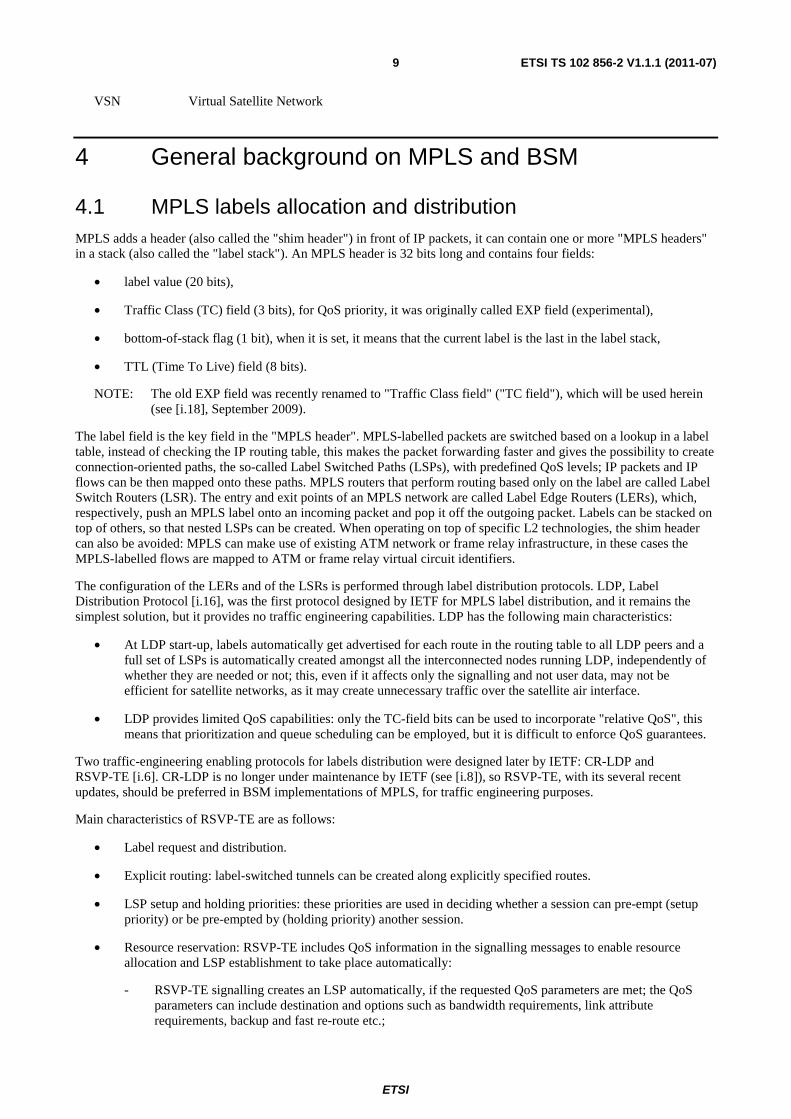
Figure 4.1 illustrates the behaviour of a DiffServ-enabled MPLS node (e.g. an ST) with a practical example; three DiffServ classes are provided through a Weighted Round Robin (WRR) scheduler. When a new connection between a source and a destination starts, an LSP is created using, for instance, RSVP-TE. We assumed in the picture that RSVP-TE packets are considered with high priority, so as if they belong to class A. During the LSP establishment process, an MPLS node receiving an RSVP-TE packet performs essentially three actions:
1) Determine the output link according to the routing table.
2) Retrieve information on which PHB the advertised label is to be bound.
3) Actualize the data related to the being-created LSP (in/out labels and in/out interfaces) in the label switching table.

ETSI
ETSI TS 102 856-2 V1.1.1 (2011-07)11
The RSVP-TE packet is then forwarded to the next node (or next ST) to continue creating the LSP. Later, when MPLS data packets arrive, the information stored in the label forwarding table will be used for switching/forwarding purposes. In the present example, three different queues are defined in each output link of the MPLS network to support the three desired traffic classes, PHBs are implemented with a WRR scheduler, which is used to select the sequence of packets to be served among the different queues.
Routing Table
...
Class A
Class B
Class C
Cla
ss A
Cla
s s B
Cla
ss C
MPLS Node
Output Link
Input Link
WRR
OutputLinK
WRR
Out. 1
Out. 2@IP 1
@IP 2Out. 1
RSVP-TE messageto setup an LSP forClass-C data packets
LSP for Class-Cdata packets
...
Label Switching Table
IN Int./Label
...
OUT Int./Label
Service Class.
Out. 2
Ser
vice
Cla
ss.
Figure 4.1: Functional diagram of a node with MPLS capabilities
4.3 MPLS/BSM architectural issues and relation to TS 102 856-1
The main fact that should be considered to understand the issues in the integration of MPLS in BSM networks is that the SI-SAP is an interface between layer-3 (L3) and layer-2 (L2), on the other hand MPLS packets reaching an ST have to be switched "below" IP, based on their label, so IP headers are not processed (MPLS is normally considered layer-2.5).
TS 102 856-1 [13] discusses how this general issue can be addressed. Basically there the following three approaches are presented:
• an LSR is fully integrated with the ST (scenario A);
• an LSR is externally attached to an ST (so the LSR is not considered part of the MPLS/BSM network) and the ST can operate in two ways:
- MPLS packets are tunnelled over IP across an unmodified BSM network (scenario B),
- MPLS is transported via a satellite L2 modem, i.e. the ST only contains a L2 bridge (scenario C).
The present document focuses on scenario A (LSR fully integrated with the ST), since it is considered the most complete and relevant case for BSM networks, whereas, as better explained in TS 102 856-1 [13], Scenario B and C are of little or no relevance.
ETSI
ETSI TS 102 856-2 V1.1.1 (2011-07)12
4.4 Relevant BSM issues and organization of the present document
The BSM architecture has been so far designed to transport L3 Protocol Data Units (PDUs), namely IP packets (see [4], clause 6.2.1.2), and thus the signaling and the procedures in the Control and Management planes have been designed accordingly. The use of MPLS in BSM networks introduces the need of transporting different types of PDU and to foresee the handling of additional signaling on the Control and the Management planes. The present clause gives a short overview of the issues identified on the three planes (User, Control, and Management plane), when integrating an LSR in a BSM-compliant ST.
On the U-plane, the Service Data Unit (SDU) at the SI-SAP can also be an IP packet encapsulated with a MPLS shim header, which is 32 bits long. The U-plane also has to transfer MPLS-based signalling, but this has no major effects since signaling protocols like LDP and RSVP-TE run on top of IP. These issues will be considered in clause 5.
As already mentioned, the current BSM C-plane only considers treatment of IP packets. There are at least three areas which need to be considered (they will be addressed in clause 6):
• Forwarding policies for MPLS signaling: RSVP-TE (or LDP) packets will be sent to every MPLS-enabled ST in order to setup LSPs; these packets need to be treated with higher priority than normal data-plane IP packets, so proper forwarding policies for this type of signaling have to be available and ready in the ST at LSP setup.
• QoS and resource allocation: LSPs have to be mapped onto SD resources, this needs to be performed, according to BSM philosophy, by means of QIDs (see [5] to [7]) and it can be done in different ways according to the possible situations.
• MPLS interfaces at SI-SAP: in order to transfer a PDU through the SI-SAP, an ST normally associates the IP destination address of the IP packet to be transmitted over the satellite interface with a BSM_ID (this includes an SI-SAP address resolution procedure [4]); in an MPLS-enhanced ST it would be preferable not to inspect the IP header when an MPLS-labeled packet has to be sent (the purpose of having MPLS is in fact in saving the IP-layer processing), but to derive the destination BSM_ID from the (top-most) MPLS label rather than from the IP-address.
Clause 7 will address the remaining M-Plane issues. Performance monitoring procedures and performance parameters for BSM networks have already been defined in a set of technical specifications (see [8] to [11]). When running an LSP over a satellite interface, it is important to monitor the link attributes in order to guarantee the provision of the QoS levels agreed at the LSP setup (the link transmission rate may change, e.g. due to degradation of the weather conditions); so the BSM Network Management System (BNMS) needs to make use of the tools provided for Performance Management at the SI-SAP in the mentioned technical specifications.
4.5 Relevance of the present document for Scenarios B and C Scenarios B and C were introduced in TS 102 856-1 [13].
In Scenario B, the BSM network is processing only IP packets. The QoS requirements linked to the encapsulated MPLS packet have to be mapped onto the encapsulating IP header, so that the BSM entities can process and forward these IP datagrams following exactly the same procedures as with native IP datagrams that contain no encapsulated MPLS packets. The issues discussed in the present document in clauses 5 and 6 (U- and C-plane) are not applicable to this scenario, but the issues discussed in clause 7 (M-plane) remain valid also for this scenario.
In Scenario C the ST acts as a L2 bridge between its terrestrial interface and its satellite interface; so MPLS runs on top of the satellite link, as if it is the prolongation of the terrestrial L2 interfaces of the ingress and egress STs. The ingress and egress STs do not have LER/LSR functionalities, and so they do not perform any label swapping, pushing or popping and do not handle any MPLS signalling, the LSP configuration for the satellite link has to be performed manually before the LSP is setup. All the issues discussed in the present document are not applicable to this scenario, also because for this type of STs the SI-SAP interface cannot be defined.
ETSI
ETSI TS 102 856-2 V1.1.1 (2011-07)13
5 U-plane MPLS data transfer in BSM Systems In an ST the SI-SAP provides to the higher layers a data transfer service, which is used to transfer PDUs from the Satellite-Independent (SI) layers down to the Satellite-Dependent (SD) layers at the ingress ST, and from the SD layers to the SI layers at the egress ST. This is done by taking the SI PDU as a Service Data Unit (SDU) and encapsulating it into a U-plane data transfer primitives: The SI-U-UNITDATA-req primitive is invoked at the sender, the SDU encapsulated in the primitive and passed down to the SD layers; at the peer ST, the SD layers deliver the SDU to the upper layers using a data transport SI-U-UNITDATA-ind primitive, the SDU is extracted and passed as a PDU to the SI layers.
In an MPLS-enable ST, each SDU at the SI-SAP shall contain a complete IP datagram plus all its MPLS headers.
So far the possible SDUs which are accepted by an SI-SAP are only L3 PDU, so basically IP packets: "each SDU shall contain a complete IP datagram" (from [4], clause 6.2.1.2). In fact, introducing MPLS, means allowing other kinds of PDUs to be accepted as SDU by the SI-SAP, in particular allowing IP packets encapsulated in one MPLS shim header (or encapsulated in more nested MPLS shim headers). This only changes the definition of the format of the data transferred at the SI-SAP. The lower layers (below the SI-SAP) are not affected, and may behave as usual, e.g. may segment the IP packet as required for transmission over the air interface.
The SDU that is delivered at the egress ST shall be identical to the SDU that was submitted by the ingress ST. This means that the SDU delivered at the destination ST can be directly submitted to the destination IP layer or to the MPLS layer with no additional processing, reassembly or similar. Anyway the egress SI-SAP needs to know whether the SDU has to be delivered to the IP layer or to the MPLS layer. Thus, at the egress SI-SAP, it is important to be able to distinguish plain IP packets from MPLS packets. This can be done by inspecting the SDU_Type field in the -ind primitive.
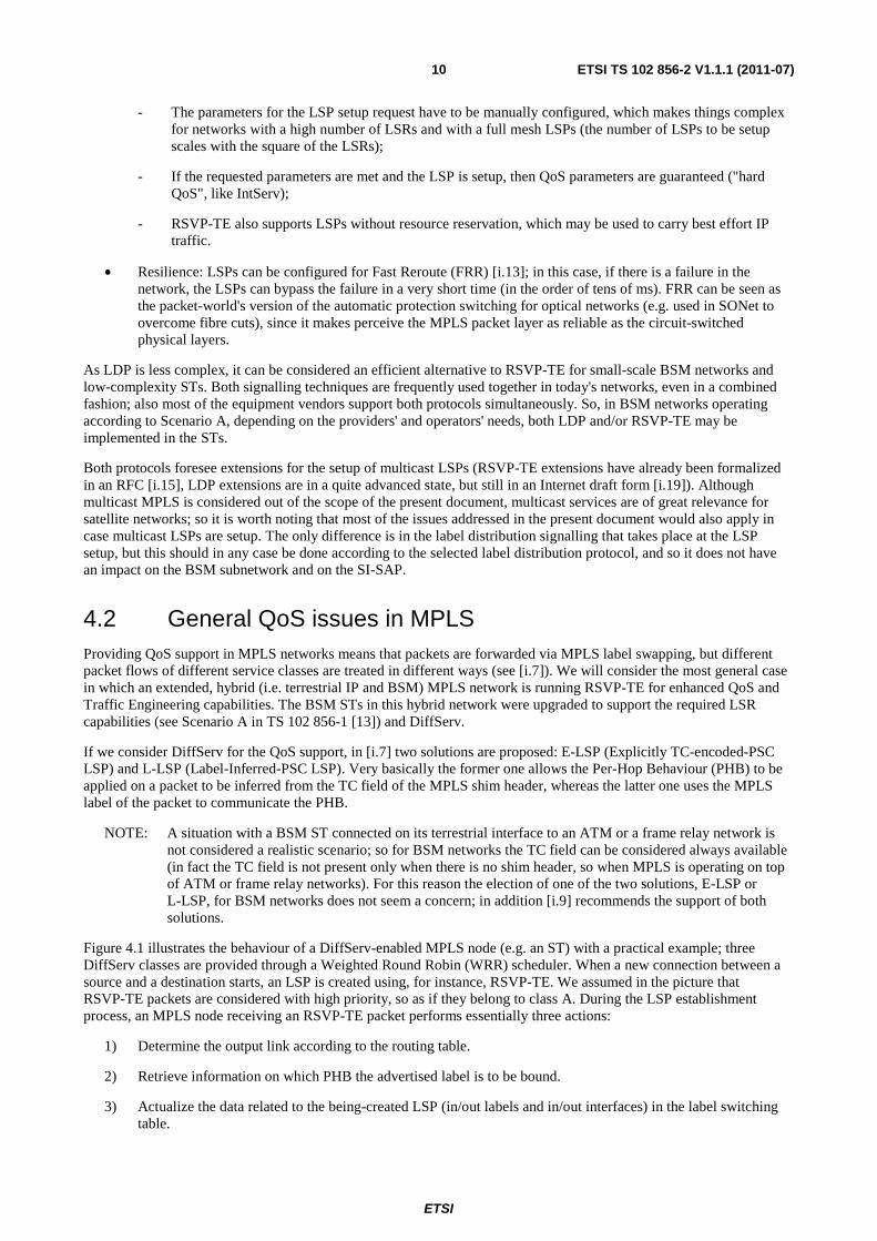
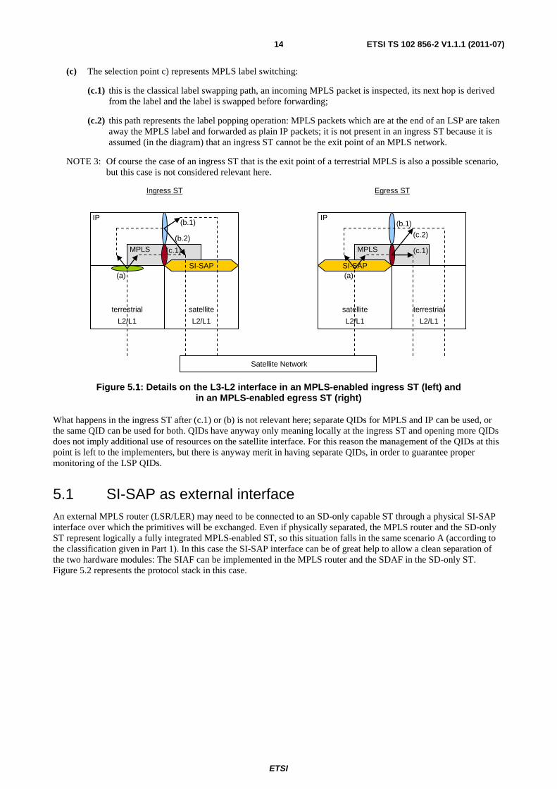
In this respect it is worth to note that an MPLS-enabled ST will always need to process traffic that is a mixture of IP and MPLS packets. In fact if it is a LER, it will receive IP packets and may have to push an MPLS label in front of them before forwarding over the satellite interface (or similarly to pop an MPLS label from a packet received on the satellite interface before forwarding to the terrestrial interface). If the ST is a simple LSR, so it is not performing label pushing or popping, it will have in any case to handle label distribution protocols, which are plain IP packets. In addition to that there might always be traffic which is not mapped onto LSPs, and so has to be forwarded by classical IP routing. Figure 5.1 shows the details on the packet processing at the interface between the L3 and the L2 and the interaction between SI-SAP, the IP layer and the MPLS layer, and how packets are forwarded to one or the other. The arrows numbered in the diagram can be explained as follows:
(a) This Service Access Point (SAP) represents both the SI-SAP in the egress ST and the terrestrial L2 SAP in the ingress ST; it selects the L3 module (IP or MPLS) to which the incoming packet has to be passed by looking at the SDU type: if the field indicates MPLS, the SDU is forwarded to the MPLS layer, otherwise to the IP layer. At the egress ST this selection could also be made based on the source BSM_ID, so on an L2 address identifier of the ingress ST (see also note 1).
NOTE 1: In many BSM implementations, not only related to MPLS, it may be important at the egress SI-SAP to be able to identify the ingress ST, e.g. a common situation could be a receiving hub which needs to identify the transmitting ST; this would be equivalent to a terrestrial router, which is always able to identify the incoming interface since they are physically separated. The L2 source address information is always available at the SD layers of the egress ST (e.g. the hub can derive it from the scheduling plan), so it is considered wise to pass this information to the SI layers through an SI-SAP primitive; this can be done with the BSM_ID field in the U-plane primitive, as explained in annex A.
(b) This selection point represents IP classification and routing:
(b.1) this path represents the routing of plain IP packets, which do not need to go through the MPLS module, but can be sent directly over the SI-SAP (in the ingress ST) or to the outgoing terrestrial interface (in the egress ST);
(b.2) this path represents IP packets that need to enter into an MPLS path (a LSP), thus they need to get a new MPLS label; thus this path represents the label pushing operation in an ingress ST that acts as a LER; it is not present in an egress ST because it is assumed (in the diagram) that an egress ST cannot be the entry point of an MPLS network.
NOTE 2: Of course the case of an egress ST that is the entry point of a terrestrial MPLS is also a possible scenario, but this case is not considered relevant here.
ETSI
ETSI TS 102 856-2 V1.1.1 (2011-07)14
(c) The selection point c) represents MPLS label switching:
(c.1) this is the classical label swapping path, an incoming MPLS packet is inspected, its next hop is derived from the label and the label is swapped before forwarding;
(c.2) this path represents the label popping operation: MPLS packets which are at the end of an LSP are taken away the MPLS label and forwarded as plain IP packets; it is not present in an ingress ST because it is assumed (in the diagram) that an ingress ST cannot be the exit point of an MPLS network.
NOTE 3: Of course the case of an ingress ST that is the exit point of a terrestrial MPLS is also a possible scenario, but this case is not considered relevant here.
terrestrial
L2/L1
IP
MPLS
satellite
L2/L1
SI-SAP(a)
(b.1)
(b.2)
satellite
L2/L1
IP
MPLS
terrestrial
L2/L1
SI-SAP(a)
(c.2)
(c.1)
Satellite Network
Egress STIngress ST
(c.1)
(b.1)
Figure 5.1: Details on the L3-L2 interface in an MPLS-enabled ingress ST (left) and in an MPLS-enabled egress ST (right)
What happens in the ingress ST after (c.1) or (b) is not relevant here; separate QIDs for MPLS and IP can be used, or the same QID can be used for both. QIDs have anyway only meaning locally at the ingress ST and opening more QIDs does not imply additional use of resources on the satellite interface. For this reason the management of the QIDs at this point is left to the implementers, but there is anyway merit in having separate QIDs, in order to guarantee proper monitoring of the LSP QIDs.
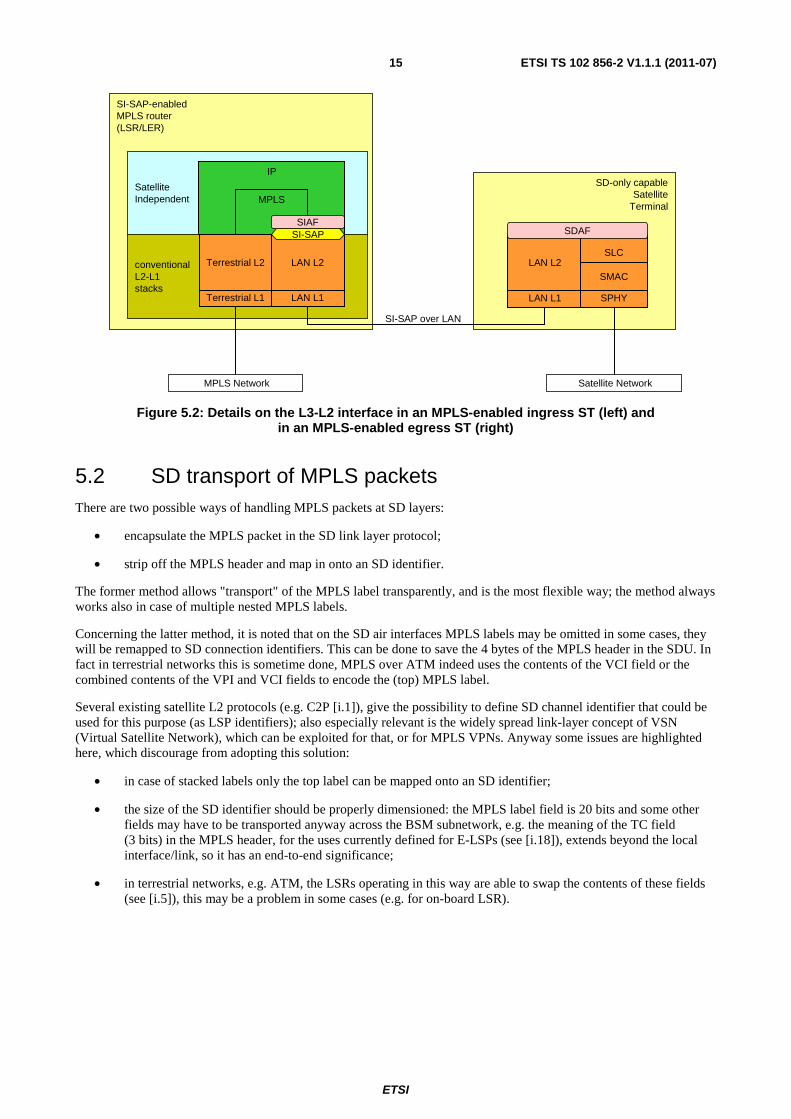
5.1 SI-SAP as external interface An external MPLS router (LSR/LER) may need to be connected to an SD-only capable ST through a physical SI-SAP interface over which the primitives will be exchanged. Even if physically separated, the MPLS router and the SD-only ST represent logically a fully integrated MPLS-enabled ST, so this situation falls in the same scenario A (according to the classification given in Part 1). In this case the SI-SAP interface can be of great help to allow a clean separation of the two hardware modules: The SIAF can be implemented in the MPLS router and the SDAF in the SD-only ST. Figure 5.2 represents the protocol stack in this case.
ETSI
ETSI TS 102 856-2 V1.1.1 (2011-07)15
SI-SAP-enabled MPLS router(LSR/LER)
SatelliteIndependent
IP
MPLS
conventional L2-L1stacks
SD-only capableSatellite
Terminal
LAN L1
LAN L2
LAN L1
LAN L2
SIAF
SLC
SDAF
SPHY
SMAC
SI-SAP over LAN
SI-SAP
Terrestrial L1
Terrestrial L2
Satellite NetworkMPLS Network
Figure 5.2: Details on the L3-L2 interface in an MPLS-enabled ingress ST (left) and in an MPLS-enabled egress ST (right)
5.2 SD transport of MPLS packets There are two possible ways of handling MPLS packets at SD layers:
• encapsulate the MPLS packet in the SD link layer protocol;
• strip off the MPLS header and map in onto an SD identifier.
The former method allows "transport" of the MPLS label transparently, and is the most flexible way; the method always works also in case of multiple nested MPLS labels.
Concerning the latter method, it is noted that on the SD air interfaces MPLS labels may be omitted in some cases, they will be remapped to SD connection identifiers. This can be done to save the 4 bytes of the MPLS header in the SDU. In fact in terrestrial networks this is sometime done, MPLS over ATM indeed uses the contents of the VCI field or the combined contents of the VPI and VCI fields to encode the (top) MPLS label.
Several existing satellite L2 protocols (e.g. C2P [i.1]), give the possibility to define SD channel identifier that could be used for this purpose (as LSP identifiers); also especially relevant is the widely spread link-layer concept of VSN (Virtual Satellite Network), which can be exploited for that, or for MPLS VPNs. Anyway some issues are highlighted here, which discourage from adopting this solution:
• in case of stacked labels only the top label can be mapped onto an SD identifier;
• the size of the SD identifier should be properly dimensioned: the MPLS label field is 20 bits and some other fields may have to be transported anyway across the BSM subnetwork, e.g. the meaning of the TC field (3 bits) in the MPLS header, for the uses currently defined for E-LSPs (see [i.18]), extends beyond the local interface/link, so it has an end-to-end significance;
• in terrestrial networks, e.g. ATM, the LSRs operating in this way are able to swap the contents of these fields (see [i.5]), this may be a problem in some cases (e.g. for on-board LSR).

ETSI
ETSI TS 102 856-2 V1.1.1 (2011-07)16
6 C-plane procedures for MPLS in BSM Systems The issues arising in the C-plane from the introduction of MPLS derive from the fact that the way, in which MPLS packets have to be forwarded through the SI-SAP, needs to be specified. Basically there are only two issues to be specified, namely the service level which has to be assigned to each LSP (i.e. the QID to be selected), and the next hop destination (i.e. the BSM_ID). The former one will be addressed in clause 6.2, and the latter one in clause 6.3; these two clauses will discuss the processing of the MPLS signalling, and how this affects the SI-SAP procedures.
Anyway all this assumes that the MPLS signalling is properly handled, and that MPLS signalling packets can be correctly received and forwarded. So before proceeding with the two main issues mentioned above, we will first clarify what has to be statically configured in an MPLS-enabled ST in order to guarantee proper reception and forwarding of the MPLS signalling.
6.1 Forwarding policies for MPLS signaling MPLS signaling packets are used to setup LSPs and to distribute labels, so that the MPLS switch can be configured for the different operations which need to be performed: label swapping (at the LSR), label pushing and popping (at the LER). This signaling is performed by means of IP-based protocol, RSVP-TE or LDP. These signaling packets are thus IP packets which need to receive higher priority and better service level (at least with respect to the dropping probability) than normal data-plane IP packets (see also Figure 4.1).
For this reason it is recommended that proper forwarding policies are guaranteed in the ingress ST for this type of signaling packets. This means that for example suitable QIDs may have to be statically configured; they can be opened at terminal startup and configured to wait for these signalling packets. This would guarantee that, at least at the SI-SAP level, resources for forwarding these packets are available and ready in the ST at LSP setup; how this is then managed at SD layer and how the physical resources are allocated, is out of the scope of the present document.
It is recommended that in an MPLS-enabled ST there is at least one static QID, configured and used to forward MPLS signalling over the satellite interface, we name this QID the MPLS-signalling QID. The following parameters need to be provided when creating this QID [6]: IP_queue_label, QIDSPEC, destination BSM_ID, lease time. Some recommendations on how to select these parameters are given in clauses 6.1.1, 6.1.2 and 6.1.3.
6.1.1 MPLS-signalling QID: IP_queue_label and QIDSPEC parameters
The value of the IP_queue_label parameter is implementation dependent and not relevant here; anyway an example may help to understand its meaning and may also help in the choice of QIDSPEC.
For example, at IP level the MPLS signalling packets could be mapped onto a DiffServ Assured Forwarding (AF) class of high priority and low drop precedence (e.g. AF11, whose DSCP is 0010102). For this type of AF classes, at QID creation a rate R parameter has to be specified in the QIDSPEC, whereas the specification of the slack term S in the QIDSPEC of an AF QID is optional [7]. The parameter R represents the minimum provided transmission rate at the SD layer, the parameter S defines the maximum expected packet queuing delay, i.e. the time the packet spends in the ST at the outgoing satellite interface waiting for being selected for transmission. It is suggested that a low value for R is selected, while the parameter S, even if optional, is specified indicating the maximum time the MPLS signalling packet can wait before being forwarded.
6.1.2 MPLS-signalling QID: destination BSM_ID parameter
The destination BSM_ID for these MPLS signalling packets can be derived by means of usual SI-SAP address resolution primitives, as these packets are plain IP packets.
6.1.3 MPLS-signalling QID: lease time parameter
The lease time of the QID meant to be used to forward MPLS signalling has to be "0x0", which means that the QID is of hard state and it does not expire.
ETSI
ETSI TS 102 856-2 V1.1.1 (2011-07)17
6.2 QoS and resource allocation In terms of QoS, MPLS requires minor C-plane modifications in order to be accommodated in a BSM-compliant ST. When receiving MPLS signalling packets, QIDs have to be opened, modified or closed. Each LSP may be mapped onto a single QID or multiple LSPs may be mapped onto the same QID, also an LSP may be mapped onto multiple QIDs. In fact the primary use of multiple QIDs is to provide different QoS, so in many cases multiple LSPs may be mapped onto the same QID. Also, in some cases there may be benefits to map one label to multiple QIDs (e.g. E-LSP may require different QIDs or QoS levels depending on the TC field).
According to this LSP mapping, it is possible to define the Diffserv/Intserv-based QID selection. At LSP setup, the requested QoS levels for the new LSP are communicated to the MPLS router by means of the existing label distribution protocols (RSVP-TE or LDP); this information can be used for the allocation of the physical satellite resources, so it should be propagated down to the SD layers through the SI-SAP through the SI-C-QUEUE_* primitives: SI-C-QUEUE_OPEN-*, SI-C-QUEUE_MODIFY-*, and SI-C-QUEUE_CLOSE-*.
As a consequence, QID management procedures, and the following SD resource allocation, should be triggered, according to the characteristics of the LSP which is mapped onto the relevant QID. This can be done in different ways, e.g. QID can be static or dynamic, and considering the QoS levels specified (e.g. PHB) for the associated LSP. This will be detailed in clauses 6.2.1 and 6.2.2 for DiffServ and IntServ IP flows.
Anyway it is recommended that MPLS packets are mapped onto QIDs separated from the QIDs used for plain IP traffic.
Concerning the allocation of the QID_label values, which are selected at QID creation, the following should be noted. It might be possible to use the numeric value of the MPLS labels for the QID_label parameter; anyway the QID_label has only local significance at the ingress ST. So this would not bring any advantage, but it might be a simple and straightforward policy for allocating the QID_label values in case of LSP-associated QIDs.
6.2.1 DiffServ
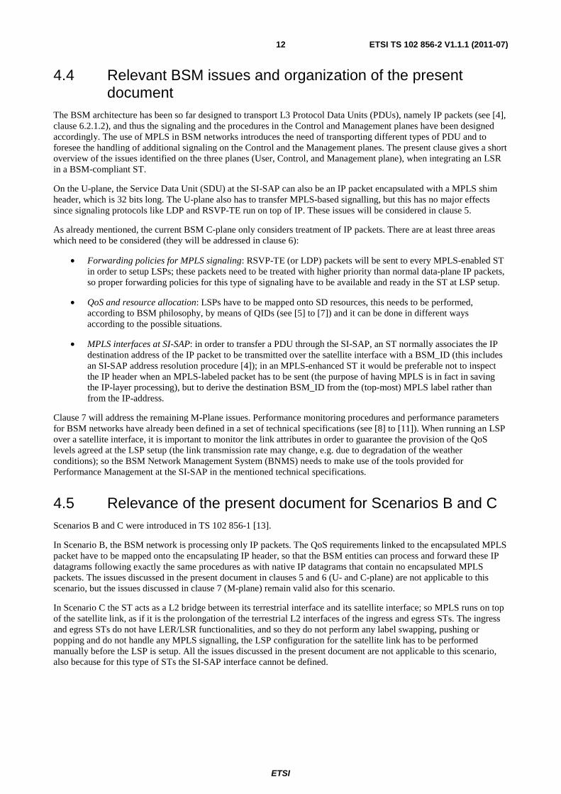
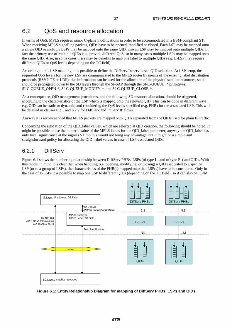
Figure 6.1 shows the numbering relationship between DiffServ PHBs, LSPs (of type L- and of type E-) and QIDs. With this model in mind it is clear that when handling (i.e. opening, modifying, or closing) a QID associated to a specific LSP (or to a group of LSPs), the characteristics of the PHB(s) mapped onto that LSP(s) have to be considered. Only in the case of E-LSPs it is possible to map one LSP to different QIDs (depending on the TC field), so it can also be: L<M.
QIDs
IP Layer: IP address, DS Field
MPLS Sublayer: MPLS Label, TC Field
SD Layers: satellite resources
SI-SAP
TS 102 464 (SES BSM; Interworking
with DiffServ QoS)
RFC 3270(MPLS Support of DiffServ)
This Specification
DiffServ PHBs
…
…
L-LSPs
QIDs
DiffServ PHBs
…
…
E-LSPs
N:1 L:M
1:1 N:1
Figure 6.1: Entity Relationship Diagram for mapping of DiffServ PHBs, LSPs and QIDs
ETSI
ETSI TS 102 856-2 V1.1.1 (2011-07)18
For the characteristics of the DiffServ traffic, which is basically made of aggregated flows, it may be advisable to have a set of static, pre-configured QIDs, which are quasi-statically mapped to the existing DiffServ-based LSPs.
The parameters to be used in the primitives (IP_queue_label, QIDSPEC, destination BSM_ID, lease time) can be selected according to [7]; the key criteria for the choice of these parameters are summarized in the following.
The IP_queue_label value is implementation dependent; one IP_queue_label per Behaviour Aggregate (BA) should be selected. Packets belonging to the same BA, or to a group of PHBs with the same queue servicing policy, but different drop precedence, could go in the same queue. Alternatively one IP_queue_label per PHB can also be selected.
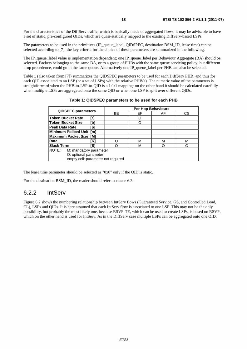
Table 1 (also taken from [7]) summarizes the QIDSPEC parameters to be used for each DiffServ PHB, and thus for each QID associated to an LSP (or a set of LSPs) with the relative PHB(s). The numeric value of the parameters is straightforward when the PHB-to-LSP-to-QID is a 1:1:1 mapping; on the other hand it should be calculated carefully when multiple LSPs are aggregated onto the same QID or when one LSP is split over different QIDs.
Table 1: QIDSPEC parameters to be used for each PHB
QIDSPEC parameters Per Hop Behaviours
BE EF AF CS Token Bucket Rate [r] O Token Bucket Size [b] O Peak Data Rate [p] Minimum Policed Unit [m] Maximum Packet Size [M] Rate [R] O M M M Slack Term [S] O M O O NOTE: M: mandatory parameter O: optional parameter empty cell: parameter not required
The lease time parameter should be selected as "0x0" only if the QID is static.
For the destination BSM_ID, the reader should refer to clause 6.3.
6.2.2 IntServ
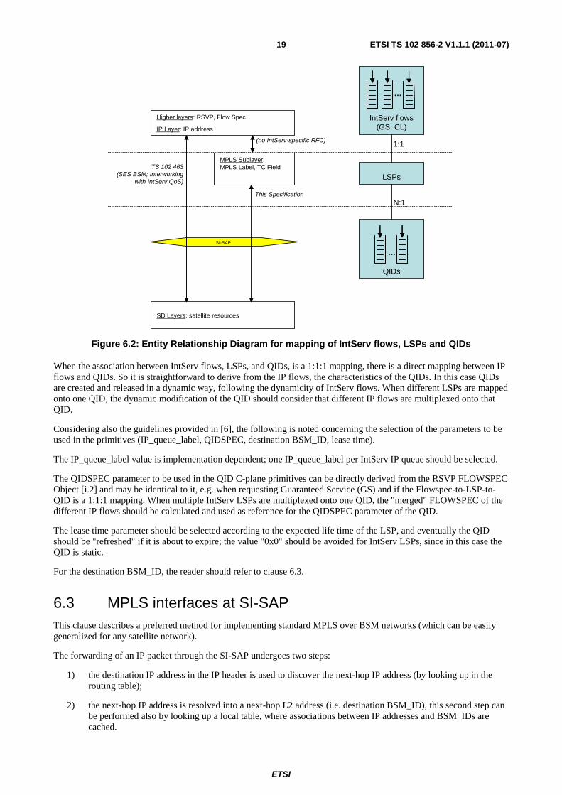
Figure 6.2 shows the numbering relationship between IntServ flows (Guaranteed Service, GS, and Controlled Load, CL), LSPs and QIDs. It is here assumed that each IntServ flow is associated to one LSP. This may not be the only possibility, but probably the most likely one, because RSVP-TE, which can be used to create LSPs, is based on RSVP, which on the other hand is used for IntServ. As in the DiffServ case multiple LSPs can be aggregated onto one QID.
ETSI
ETSI TS 102 856-2 V1.1.1 (2011-07)19
QIDs
Higher layers: RSVP, Flow Spec
IP Layer: IP address
MPLS Sublayer: MPLS Label, TC Field
SD Layers: satellite resources
SI-SAP
TS 102 463 (SES BSM; Interworking
with IntServ QoS)
(no IntServ-specific RFC)
This Specification
IntServ flows(GS, CL)
…
…
LSPs
N:1
1:1
Figure 6.2: Entity Relationship Diagram for mapping of IntServ flows, LSPs and QIDs
When the association between IntServ flows, LSPs, and QIDs, is a 1:1:1 mapping, there is a direct mapping between IP flows and QIDs. So it is straightforward to derive from the IP flows, the characteristics of the QIDs. In this case QIDs are created and released in a dynamic way, following the dynamicity of IntServ flows. When different LSPs are mapped onto one QID, the dynamic modification of the QID should consider that different IP flows are multiplexed onto that QID.
Considering also the guidelines provided in [6], the following is noted concerning the selection of the parameters to be used in the primitives (IP_queue_label, QIDSPEC, destination BSM_ID, lease time).
The IP_queue_label value is implementation dependent; one IP_queue_label per IntServ IP queue should be selected.
The QIDSPEC parameter to be used in the QID C-plane primitives can be directly derived from the RSVP FLOWSPEC Object [i.2] and may be identical to it, e.g. when requesting Guaranteed Service (GS) and if the Flowspec-to-LSP-to-QID is a 1:1:1 mapping. When multiple IntServ LSPs are multiplexed onto one QID, the "merged" FLOWSPEC of the different IP flows should be calculated and used as reference for the QIDSPEC parameter of the QID.
The lease time parameter should be selected according to the expected life time of the LSP, and eventually the QID should be "refreshed" if it is about to expire; the value "0x0" should be avoided for IntServ LSPs, since in this case the QID is static.
For the destination BSM_ID, the reader should refer to clause 6.3.
6.3 MPLS interfaces at SI-SAP This clause describes a preferred method for implementing standard MPLS over BSM networks (which can be easily generalized for any satellite network).
The forwarding of an IP packet through the SI-SAP undergoes two steps:
1) the destination IP address in the IP header is used to discover the next-hop IP address (by looking up in the routing table);
2) the next-hop IP address is resolved into a next-hop L2 address (i.e. destination BSM_ID), this second step can be performed also by looking up a local table, where associations between IP addresses and BSM_IDs are cached.

ETSI
ETSI TS 102 856-2 V1.1.1 (2011-07)20
NOTE: For the purpose of the present document the latter process will be called SI-SAP address resolution.
So, when forwarding PDUs across the SI-SAP over the satellite interface, an ST needs to keep track of the association between next-hop IP addresses and BSM_IDs. If the association is not known (e.g. when the first packet destined to a specific IP address is received), a look-up in the routing table and then the SI-SAP address resolution procedure is performed and then the next-hop BSM_ID is cached (to avoid repeating the procedure at every incoming IP packet).
The same operation is also performed when MPLS packets need to be forwarded across the SI-SAP over the satellite interface, with the difference that an MPLS-enabled ST should not inspect the IP header but just the top-most MPLS label. In this case standard MPLS nodes store the next-hop IP address, associated with a label, in specific tables (the LSR MIBs, see [i.11]). This information is stored in the object mplsOutSegmentNextHopAddr located in an mplsOutSegmentEntry in the mplsOutSegmentTable (which in fact is a sequence of mplsOutSegmentEntry). When the SI-SAP PDU that transports the MPLS packet is built, the following operations are performed:
1) the next-hop IP address is taken from the LSR MIB in the object mplsOutSegmentNextHopAddr [i.11], without inspecting the IP header;
2) after that, the next-hop IP address can be resolved into a next-hop BSM_ID, through an SI-SAP address resolution procedure or by checking a local cache.
In this way the ST can keep track of the association between MPLS labels and destination BSM_IDs.
Considering the broadcast nature of the satellite link and the high amount of MPLS egress peers that an MPLS-enabled ingress ST may address over the same satellite link, there is a need for an efficient management of the labels. In fact the broadcast nature of the satellite link would require coordination of the MPLS label distribution among many STs, if they all shared the same interface. In reality at every ST, MPLS labels need to be unique only on an MPLS interface, namely on every incoming or outgoing interface which is MPLS-capable (see also [i.11]). This suggests that a good definition of the MPLS interface at the SI-SAP can allow reuse of the same MPLS label space on different ingress-egress ST peers.
For this reason it is suggested here to adopt the destination BSM_IDs as identifier of the MPLS outgoing interface and the source BSM_ID as identifier of the incoming MPLS interface. Used in this way, it is possible for an ingress MPLS-enabled ST (e.g. a hub with thousands of users) to use the same label to communicate to two different MPLS-enable egress STs over the same satellite link. The following paragraphs indicate how this can be done in practice.
The mplsInterfaceTable object [i.11] (which is a sequence of mplsInterfaceEntry) lists all MPLS-capable interfaces at the ST. The mplsInterfaceIndex (first element of the mplsInterfaceEntry) is the ifIndex of the ifTable at the ST [i.3]. In that ifTable, all local interfaces are listed and each interface index ifIndex is associated to an ifType of type "IANAifType". It is suggested to create multiple MPLS interfaces if an ST is establishing over the satellite different LSPs to different MPLS-enabled STs. For this purpose the destination BSM_IDs can be used as outgoing interface identifier (parameter mplsInterfaceIndex) in an ingress ST, and the source BSM_ID can be used as incoming interface identifier (also in the parameter mplsInterfaceIndex) in an egress ST. Considering that the SI-SAP interface has no IANAifType defined, yet, the type Ethernet-like interface should be used for these SI-SAP interfaces in the ifTable [i.3].
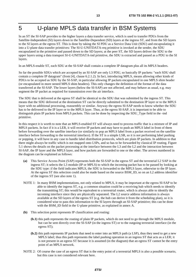
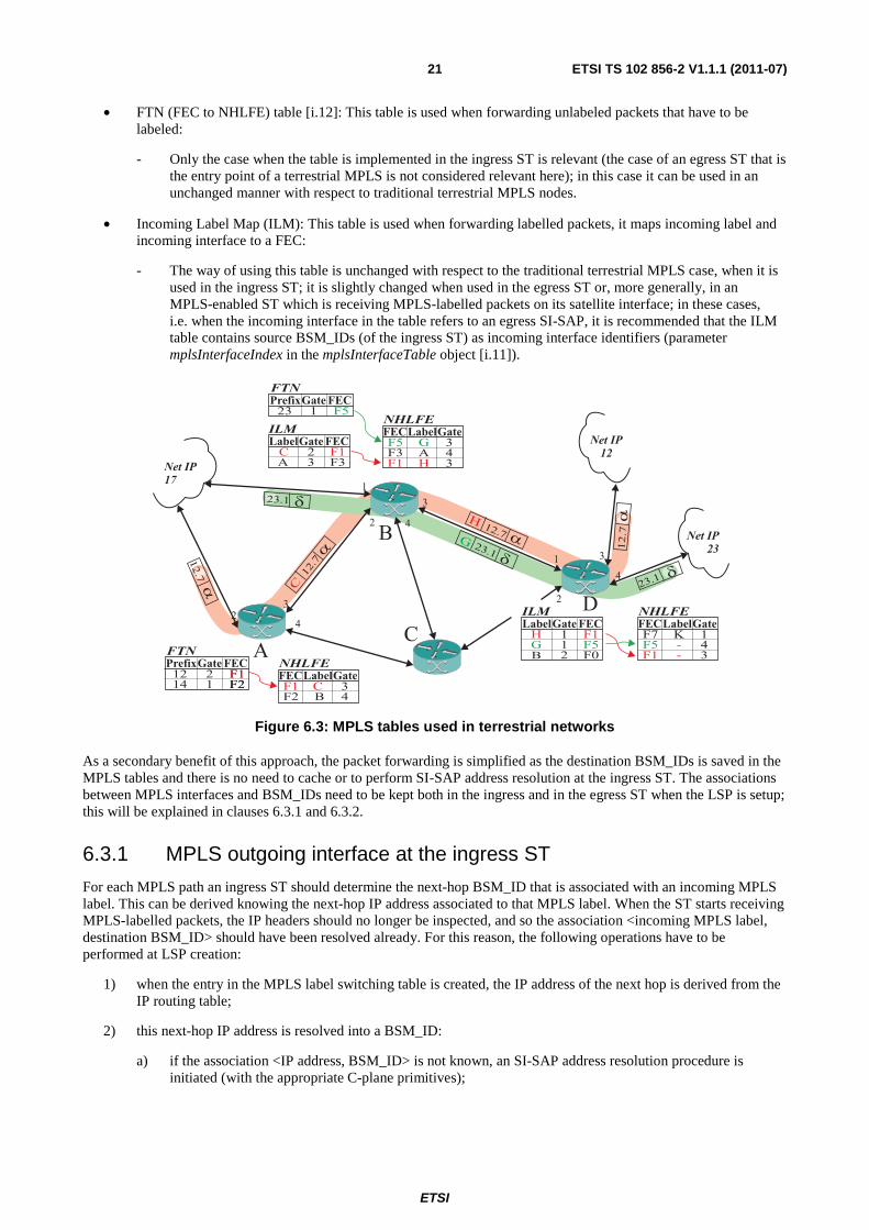
Figure 6.3 explains the use of MPLS tables (see also [i.4], [i.11], and [i.12]). So in case MPLS-enabled BSM STs are using these tables, it is proposed to slightly adapt their features as follows:
• Next Hop Label Forwarding Entry (NHLFE): This table is used for the pushing, swapping, and popping of the MPLS labels, it maps the incoming FEC (Forwarding Equivalence Class) to the actions to be performed and to the outgoing label and outgoing interface to be selected:
- The way of using this table is unchanged with respect to the traditional terrestrial MPLS case, when it is used in the egress ST; it is slightly changed when used in the ingress ST or, more generally, in an MPLS-enabled ST that is transmitting MPLS-labelled packets on its satellite interface; in these cases, i.e. when the outgoing interface in the table refers to an ingress SI-SAP, it is recommended that the NHLFE table contains BSM_IDs as outgoing interface identifiers (parameter mplsInterfaceIndex in the mplsInterfaceTable object [i.11]).
ETSI
ETSI TS 102 856-2 V1.1.1 (2011-07)21
• FTN (FEC to NHLFE) table [i.12]: This table is used when forwarding unlabeled packets that have to be labeled:
- Only the case when the table is implemented in the ingress ST is relevant (the case of an egress ST that is the entry point of a terrestrial MPLS is not considered relevant here); in this case it can be used in an unchanged manner with respect to traditional terrestrial MPLS nodes.
• Incoming Label Map (ILM): This table is used when forwarding labelled packets, it maps incoming label and incoming interface to a FEC:
- The way of using this table is unchanged with respect to the traditional terrestrial MPLS case, when it is used in the ingress ST; it is slightly changed when used in the egress ST or, more generally, in an MPLS-enabled ST which is receiving MPLS-labelled packets on its satellite interface; in these cases, i.e. when the incoming interface in the table refers to an egress SI-SAP, it is recommended that the ILM table contains source BSM_IDs (of the ingress ST) as incoming interface identifiers (parameter mplsInterfaceIndex in the mplsInterfaceTable object [i.11]).
Figure 6.3: MPLS tables used in terrestrial networks
As a secondary benefit of this approach, the packet forwarding is simplified as the destination BSM_IDs is saved in the MPLS tables and there is no need to cache or to perform SI-SAP address resolution at the ingress ST. The associations between MPLS interfaces and BSM_IDs need to be kept both in the ingress and in the egress ST when the LSP is setup; this will be explained in clauses 6.3.1 and 6.3.2.
6.3.1 MPLS outgoing interface at the ingress ST
For each MPLS path an ingress ST should determine the next-hop BSM_ID that is associated with an incoming MPLS label. This can be derived knowing the next-hop IP address associated to that MPLS label. When the ST starts receiving MPLS-labelled packets, the IP headers should no longer be inspected, and so the association <incoming MPLS label, destination BSM_ID> should have been resolved already. For this reason, the following operations have to be performed at LSP creation:
1) when the entry in the MPLS label switching table is created, the IP address of the next hop is derived from the IP routing table;
2) this next-hop IP address is resolved into a BSM_ID:
a) if the association <IP address, BSM_ID> is not known, an SI-SAP address resolution procedure is initiated (with the appropriate C-plane primitives);
FTN
FTN
ILMNHLFE
2
3
2
ILM NHLFE
1
3
Net IP
17
2
Net IP
12
1
Net IP
233
4
4
4
A
B
C
D
3F1 C
4F2 B
2 F112
1 F214
F1
F2
1 F1H
1 F5G
2 F0B
1F7 K
4F5 -
3F1 -
1 F523
2 F1C
3 F3A
3F5 G
4F3 A
3F1 H
FECGatePrefix
GateLabelFEC
NHLFE
FECGatePrefix
FECGateLabelGateLabelFEC
FECGateLabel GateLabelFEC
C
12.7
H
G23.1
23.1
23.1
12.7
12.7
�
�
�
�
�
�
�
12.7
ETSI
ETSI TS 102 856-2 V1.1.1 (2011-07)22
3) the BSM_ID of the destination ST for each label is saved in the relevant entry of the MPLS label switching table NHLFE, so that no IP processing (inspection of the IP header, IP routing, SI-SAP address resolution procedure) needs to be repeated at every incoming MPLS packet.
When the LSP is created, the ST will start receiving MPLS-labelled packets with the expected label. This label can be resolved into a BSM_ID, and this BSM_ID is used in the data transfer primitives when submitting MPLS packets (after swapping their label) to the SD layers.
The BSM_ID is used then by the lower layers to deliver the SDU (i.e. the MPLS packet) over the BSM subnetwork to the intended next-hop MPLS layer inside the egress ST (next hop LSR or LER).
6.3.2 MPLS incoming interface at the egress ST
At the egress ST a dual procedure has to take place. The reason is that an MPLS node applies the appropriate operations on an MPLS-labelled packet (swapping or popping), also based on the incoming interface of the packet (see use of the ILM table, previously explained); this is done to avoid inspection of the IP header. For this reason the source BSM_ID of a packet arriving at an egress ST could be seen as the incoming interface in a traditional terrestrial MPLS node, and it could be saved appropriately in the ILM table.
In order to guarantee this, the following operations have to be performed at LSP creation:
1) when the entry in the MPLS label switching table is created, the SI layers in the egress ST receive an MPLS signalling packet which is a plain IP packet; this packet is delivered by the SD layer to the SI layers across the SI-SAP with a U-plane primitive and the source BSM_ID is also transmitted in the primitive (see Annex A);
NOTE: The BSM_ID address of the previous hop is assumed to be known at the SD layers of the egress ST. It is normally known because the L2 source address is known, due to the way many satellite networks are designed (e.g. in a transparent star network the gateway always knows the transmitting ST). In any case it is not relevant here how the L2 address is translated into a BSM_ID at the SD layers.
2) the BSM_ID of the source ST for each label is saved in the relevant entry of the MPLS label switching table ILM.
Differently from the SI-SAP downstream address resolution, where effectively an SI-SAP address resolution procedure with appropriate SI-SAP C-plane primitives may have to be triggered, in this case there is no real address resolution procedure, but the association <incoming MPLS label, source BSM_ID> has to be stored by the egress ST at the time the LSP is created, to be used for the subsequent processing of the MPLS-labelled packets.
When the LSP is created, the ST will start receiving MPLS-labelled packets with the expected label and the expected source BSM_ID. The BSM_ID will be set by the SD layers in the data transfer primitives when passing MPLS packets from the lower layer to the higher layers across the SI-SAP. The BSM_ID can be used then at the SI-SAP (together with the incoming MPLS label) to check the ILM table for the appropriate operations to be performed.
7 M-plane procedures in support of MPLS When running an LSP over a satellite interface, it is important to monitor the link attributes in particular to respond to variable or adaptive rate of the satellite link (including outages and rain fades) or to accept/reject new resource reservation requests. In order for the BNMS to constantly monitor link attributes and establish back-up LSPs, all the IP-based instruments used in terrestrial networks can also be adopted: e.g. LMP [i.14] or OSPF-TE [i.10] can be used to propagate link attribute changes, in order to drop or re-route inadequate tunnels; Fast Re-route (FRR) extension of RSVP-TE [i.13] can be employed for local LSP tunnel restoration e.g. through switching to a backup modem.
In any case there is the need to monitor the links below IP, i.e. at the SI-SAP level, and this can be done through performance monitoring procedures and performance parameters for BSM networks that have already been defined in the technical specifications [8] to [11]. This clause describes how to use the tools provided in those specifications for the purpose of MPLS monitoring in BSM networks, also providing some examples.
ETSI
ETSI TS 102 856-2 V1.1.1 (2011-07)23
In this specific case the set of parameters named "BSM SI-SAP Performance Parameters" [9] is relevant; these are the parameters that can monitor the SI-SAP interface. They can be grouped in two levels:
• At SI-SAP-level; and
• at QID-level.
The latter ones are basic parameters related to the virtual queues at an SI-SAP and can be extracted directly from measurements thereon or used to control the QIDs; the former ones are parameters referring to the complete SI-SAP interface. Some of these parameters can be measured directly; some of them can be derived from more elementary QID attributes. These "elementary QID attributes" (introduced in [10]) constitute an additional set of basic parameters (such as packet counters and queue lengths) that can be used in practice to compute the QID-level and SI-SAP-level parameters, as described in [10].
It is clear that an LSP will always be mapped onto one or more QIDs, so in order to monitor the status of the resources serving a specific LSP, the associated QID(s) have to be monitored. Technical specification [10] describes how to calculate relevant QID parameters from the QID elementary attributes. Two relevant QID parameters could be for example:
• the QidRate parameter [11], i.e. the QID service rate, it is the number of bits of IP datagrams transmitted per second over a given QID, it can be calculated from the "elementary QID attribute" QidOctectsCounter as follows (see also [10]):
0 0
08 t T t t t
t t
QidOctetsCounter QidOctetsCounterQidRate
T= + =
=
−= ⋅ ;
• the QidSlackTerm parameter [11], i.e. the estimated packet queuing delay associated with a QID, it can be calculated from the "elementary QID attribute" QidQOctectsLen and from the QID-level parameter QidRate as follows (see also [10]):
0
0
0/ 8
t tt t
t t
QidQOctetsLenQidSlackTerm
QidRate=
==
= .
The complete list of all measurable parameters of a QID is given in [11].
Finally, in order to monitor the overall status of a satellite interface, the SI-SAP-level performance parameters should be adopted. These measurements are important e.g. to decide if the satellite interface has enough available resources to host a new LSP or not. Most of these parameters are derived locally from the QID-level parameters. Two examples of SI-SAP-level performance parameters are:
• the AllQidsAvaRate parameter, i.e. satellite capacity available for resource allocation to a specific ST;
• the AllQidsTransDelay parameter, i.e. the maximum (highest value) next-hop transmission delay among all QIDs (so it represents the worst-QID propagation delay needed to transmit 1 bit across the BSM system, up to the egress ST, it does not include queuing delay).
The complete list of all parameters measurable at an SI-SAP is also given in [11].

ETSI
ETSI TS 102 856-2 V1.1.1 (2011-07)24
Annex A (informative): Suggested update of SI-SAP U-plane primitives Version 1.1.1 of SI-SAP interface [4] is not consistent with some of the conclusions derived in the present document. Especially in the light of all considerations given in clause 5, the U-plane SI-SAP primitives are suggested to be revised as follows. The fields highlighted in bold are new or changed with respect to the primitive definition provided in [4].
Table A.1: SI-U-UNITDATA-req syntax definition
Syntax Number of bits Mnemonic SI-U-UNITDATA-req() {
SISAP_Header() 96 for further study BSM_ID (destination) 48 uimsbf BSM_ID (source) 48 uimsbf QID 24 uimsbf Padding 24 uimsbf SDU_Type 16 uimsbf for (i = 0; i < N1; i++) {
SDU_Data_Byte 8 bslbf }
} NOTE: N1: size of the SDU in bytes; uimsbf: unsigned integer, most significant bit first; bslbf: bit serial, leftmost bit first.
Table A.2: SI-U-UNITDATA-ind syntax definition
Syntax Number of bits Mnemonic SI-U-UNITDATA-IND() {
SISAP_Header() 96 for further study BSM_ID (destination) 48 uimsbf BSM_ID (source) 48 uimsbf Padding 16 uimsbf SDU_Type 16 uimsbf for (i = 0; i < N1; i++) {
SDU_Data_Byte 8 bslbf }
} NOTE: N1: size of the SDU in bytes; uimsbf: unsigned integer, most significant bit first; bslbf: bit serial, leftmost bit first.
The following is noted about the parameters in the U-plane primitives.
• SISAP_Header(): The SI-SAP Header is left for further study; it may be introduced to identify SI-SAP primitives on the physical SI-SAP interface; this may be needed if, because of the specific characteristics of the hardware interface the identification is not unequivocal, especially if the hardware interface is an external one. For the MPLS case this may not be uncommon, as explained in clause 5.1.
• BSM_ID: The BSM identifier, which is a 48 bits address, is included according to [4]; according to what previously said in clause 5, the BSM_ID of the destination is used in the -req primitive and the BSM_IDs of the source and of the destination should be used in the -ind primitive; this modifies what stated in [4].
NOTE 1: The destination BSM_ID is needed at the egress ST for multicast purposes (see clause A.1).
• QID: The Queue identifier, which is a 24 bits integer, is included according to [4]; the use of the QID field when forwarding MPLS packets is detailed in clause 6.
• Padding: It is recommended to use a padding, to align the primitive header to a multiple of 32 bits; this is not foreseen in [4], but considered meaningful when implementing the SI-SAP on an external hardware interface.
ETSI
ETSI TS 102 856-2 V1.1.1 (2011-07)25
• SDU_Type: The SDU type is included according to [4]; be a 16 bits parameter, which complies with IEEE defined EtherTypes [12]; the Ethertype space is administered as described in [i.17].
NOTE 2: The MPLS type numbers to be used for this field are 0x8847 (for unicast) and 0x8848 (for multicast). No additional SDU_Types are currently allowed in BSM, in order to avoid that the SDU_Type has to be transmitted over the air interface.
• SDU_Data_Byte: This field represents the actual SDU content, so the IP or the MPLS packet, which is N1 bytes long.
NOTE 3: It should be noted that the minimum value for the Maximum Transmission Unit (MTU) of at least 1 500 bytes (mandated in [4]) has to be increased when transmitting MPLS packets, in fact the MPLS header is 4-bytes long, so any additional MPLS header increases the minimum MTU of 4 bytes.
Technical specification [4] may be updated in the future according to what stated in this annex.
A.1 Use of the BSM_ID in the SI-SAP U-plane primitives In this clause the rationale for having the BSM_ID parameter in the U-plane primitives will be given, and in particular the reason why in some cases it may be useful to have the source and/or the destination BDM_ID will be explained.
In the ingress ST, the destination IP address of the packet has to be translated into an SD address; and this is done through the SI-SAP address resolution primitives which can retrieve the associated BSM_ID of the destination. The destination BSM_ID can then be used in the U-plane primitive SI-U-UNITDATA-req. For this reason there is the need to have a destination BSM_ID parameter in the SI-U-UNITDATA-req primitive.
At the egress ST, the information on the source and destination L2 address of a packet is always available at the SD layers, and it could, if needed, be translated by the SD layers into BSM_IDs to be used in the SI-U-UNITDATA-ind primitive. In this way the source BSM_ID would be available at the SI layers and it can be translated into a source IP address and/or can be used to perform various types of filtering or selective forwarding of the IP packet without the need to inspect its contents. This is particularly evident in the case of an MPLS-enabled egress ST (e.g. a hub), which needs to forward the MPLS-labelled packet by just looking at the incoming interface and incoming label (no inspection of the IP header): The incoming label is directly readable in the received SDU, whereas the incoming interface can be identified by the source BSM_ID (see also clause 6.3.2). For this reason there is the need to have a source BSM_ID parameter in the SI-U-UNITDATA-ind primitive.
The destination BSM_ID address in the SI-U-UNITDATA-ind primitive can be useful for multicast purposes. In the light of this, to have symmetry between ingress and egress ST and considering also that there are no additional costs in terms of resource utilization and only very minor additional complexity costs, it is suggested to include the source BSM_ID parameter also in the SI-U-UNITDATA-req primitive and to keep (as foreseen in [4]) the destination BSM_ID also in the SI-U-UNITDATA-ind primitive. Further studies on this are out of the scope of the present document.
In summary, for the purpose of using MPLS over BSM networks:
• the SI-U-UNITDATA-req primitive at the ingress ST should contain the destination BSM_ID, which is consistent with the SI-SAP definition in [4];
• the SI-U-UNITDATA-ind primitive at the egress ST should contain the source BSM_ID, this requires a change to the SI-SAP definition in [4].

ETSI
ETSI TS 102 856-2 V1.1.1 (2011-07)26
History
Document history
V1.1.1 July 2011 Publication