ts 102 744-2-1 - v1.1.1 - satellite earth stations and
TRANSCRIPT

ETSI TS 102 744-2-1 V1.1.1 (2015-10)
Satellite Earth Stations and Systems (SES); Family SL Satellite Radio Interface (Release 1);
Part 2: Physical Layer Specifications; Sub-part 1: Physical Layer Interface
�
TECHNICAL SPECIFICATION

ETSI
ETSI TS 102 744-2-1 V1.1.1 (2015-10) 2
Reference DTS/SES-00299-2-1
Keywords 3GPP, GPRS, GSM, GSO, interface, MSS, radio,
satellite, TDM, TDMA, UMTS
ETSI
650 Route des Lucioles F-06921 Sophia Antipolis Cedex - FRANCE
Tel.: +33 4 92 94 42 00 Fax: +33 4 93 65 47 16
Siret N° 348 623 562 00017 - NAF 742 C
Association à but non lucratif enregistrée à la Sous-Préfecture de Grasse (06) N° 7803/88
Important notice
The present document can be downloaded from: http://www.etsi.org/standards-search
The present document may be made available in electronic versions and/or in print. The content of any electronic and/or print versions of the present document shall not be modified without the prior written authorization of ETSI. In case of any
existing or perceived difference in contents between such versions and/or in print, the only prevailing document is the print of the Portable Document Format (PDF) version kept on a specific network drive within ETSI Secretariat.
Users of the present document should be aware that the document may be subject to revision or change of status. Information on the current status of this and other ETSI documents is available at
http://portal.etsi.org/tb/status/status.asp
If you find errors in the present document, please send your comment to one of the following services: https://portal.etsi.org/People/CommiteeSupportStaff.aspx
Copyright Notification
No part may be reproduced or utilized in any form or by any means, electronic or mechanical, including photocopying and microfilm except as authorized by written permission of ETSI.
The content of the PDF version shall not be modified without the written authorization of ETSI. The copyright and the foregoing restriction extend to reproduction in all media.
© European Telecommunications Standards Institute 2015.
All rights reserved.
DECTTM, PLUGTESTSTM, UMTSTM and the ETSI logo are Trade Marks of ETSI registered for the benefit of its Members. 3GPPTM and LTE™ are Trade Marks of ETSI registered for the benefit of its Members and
of the 3GPP Organizational Partners. GSM® and the GSM logo are Trade Marks registered and owned by the GSM Association.

ETSI
ETSI TS 102 744-2-1 V1.1.1 (2015-10) 3
Contents Intellectual Property Rights ................................................................................................................................ 5
Foreword ............................................................................................................................................................. 5
Modal verbs terminology .................................................................................................................................... 5
Introduction ........................................................................................................................................................ 5
1 Scope ........................................................................................................................................................ 6
2 References ................................................................................................................................................ 6
2.1 Normative references ......................................................................................................................................... 6
2.2 Informative references ........................................................................................................................................ 6
3 Symbols and abbreviations ....................................................................................................................... 7
3.1 Symbols .............................................................................................................................................................. 7
3.2 Abbreviations ..................................................................................................................................................... 7
4 Overview of physical layer ....................................................................................................................... 7
5 Forward bearers ........................................................................................................................................ 8
5.1 Introduction ........................................................................................................................................................ 8
5.1.1 Forward bearer types .................................................................................................................................... 8
5.1.2 L-Band Forward Frequency Range ............................................................................................................... 9
5.2 Modulation ....................................................................................................................................................... 10
5.2.1 Symbol rate ................................................................................................................................................. 10
5.2.2 Modulation schemes ................................................................................................................................... 11
5.2.2.1 16-QAM (X/X16) bearers ..................................................................................................................... 11
5.2.2.2 32-QAM (X32) bearers ......................................................................................................................... 11
5.2.2.3 64-QAM (X64) bearers ......................................................................................................................... 13
5.2.2.4 QPSK (Q/X4) bearers ........................................................................................................................... 15
5.2.2.5 Dynamic Modulation ............................................................................................................................ 16
5.2.3 Channel filtering ......................................................................................................................................... 16
5.3 Bearer types and frame formats ........................................................................................................................ 20
5.3.1 Frame numbering ........................................................................................................................................ 20
5.3.2 Forward bearer parameters ......................................................................................................................... 20
5.3.3 Forward channel frame formats .................................................................................................................. 21
5.3.4 Unique words .............................................................................................................................................. 22
5.3.4.0 General .................................................................................................................................................. 22
5.3.4.1 QPSK (Q) bearers ................................................................................................................................. 22
5.3.4.2 X (F80T1X, F80T4.5X) Bearers ........................................................................................................... 23
5.3.4.3 X4/16 (FR80T2.5X4/16-5B, FR80T5X4/16-9B) Bearers ..................................................................... 23
5.3.4.4 X16 (FR80T2.5X16-5B, FR80T5X16-9B) Bearers .............................................................................. 24
5.3.4.5 X32 (FR80T2.5X32-6B, FR80T5X32-11B) Bearers ............................................................................ 25
5.3.4.6 X64 (FR80T2.5X64-7B, FR80T5X64-13B) Bearers ............................................................................ 26
5.3.5 Pilot symbols .............................................................................................................................................. 26
5.3.6 Empty block data ........................................................................................................................................ 27
5.3.7 Scrambling .................................................................................................................................................. 27
5.3.8 Coding ........................................................................................................................................................ 27
5.3.8.0 General .................................................................................................................................................. 27
5.3.8.1 Turbo coding ......................................................................................................................................... 27
5.3.8.2 SRCC encoder ....................................................................................................................................... 28
5.3.8.3 S-Interleaver .......................................................................................................................................... 29
5.3.8.4 Puncturing, Channel Interleaving and Symbol Mapping ...................................................................... 29
5.3.8.5 80ms Outer Interleaver .......................................................................................................................... 29
5.4 PDU formats ..................................................................................................................................................... 30
6 Return bearers ........................................................................................................................................ 31
6.1 Introduction ...................................................................................................................................................... 31
6.1.1 Return bearer types ..................................................................................................................................... 31
6.1.2 L-Band Return Frequency Range ............................................................................................................... 33
6.2 Modulation ....................................................................................................................................................... 34
ETSI
ETSI TS 102 744-2-1 V1.1.1 (2015-10) 4
6.2.1 Symbol rate ................................................................................................................................................. 34
6.2.2 Modulation schemes ................................................................................................................................... 34
6.2.2.1 16-QAM (X) Bearers ............................................................................................................................ 34
6.2.2.2 π/4 QPSK Bearers ................................................................................................................................. 34
6.2.2.3 FR80T2.5/T5 Bearers ............................................................................................................................ 35
6.2.3 Channel filtering ......................................................................................................................................... 35
6.3 Bearer types and frame formats ........................................................................................................................ 36
6.3.1 Frame numbering ........................................................................................................................................ 36
6.3.2 Return bearer parameters ............................................................................................................................ 37
6.3.3 Return channel frame format ...................................................................................................................... 37
6.3.3.0 General .................................................................................................................................................. 37
6.3.3.1 5 ms Slot and Burst Definition .............................................................................................................. 37
6.3.3.2 20 ms Slot and Burst Definition ............................................................................................................ 38
6.3.3.3 80 ms Slot and Burst Definition ............................................................................................................ 39
6.3.3.3.0 General ............................................................................................................................................ 39
6.3.3.3.1 R80T0.5Q-1B .................................................................................................................................. 39
6.3.3.3.2 R80T1Q-1B ..................................................................................................................................... 43
6.3.3.3.3 Preamble Generation ....................................................................................................................... 47
6.3.3.3.4 CRC - R80 Bearers .......................................................................................................................... 48
6.3.4 Distributed Unique Word Burst Format...................................................................................................... 49
6.3.4.1 Distributed Unique Word Burst Format - R80 Bearers ......................................................................... 49
6.3.4.2 Distributed Unique Word Burst Format - R5/R20 bearers .................................................................... 51
6.3.5 Burst Preamble (R5/R20 bursts) ................................................................................................................. 52
6.3.6 Unique Words ............................................................................................................................................. 52
6.3.6.0 General .................................................................................................................................................. 52
6.3.6.1 QAM (X) Bearers .................................................................................................................................. 52
6.3.6.2 π/4 QPSK (Q) Bearers ........................................................................................................................... 54
6.3.7 Scrambling .................................................................................................................................................. 55
6.3.8 Coding ........................................................................................................................................................ 55
6.3.8.0 General .................................................................................................................................................. 55
6.3.8.1 Turbo Coding for QAM (X/X16/Q16/X32/X64) Bearers ..................................................................... 55
6.3.8.2 Turbo Coding for R5 and R20 π/4 QPSK (Q) Bearers .......................................................................... 55
6.3.8.3 Turbo coding for π/4 QPSK (Q) - R80 burst ......................................................................................... 56
6.3.8.4 SRCC Encoder ...................................................................................................................................... 57
6.3.8.5 S-Interleaver .......................................................................................................................................... 57
6.3.8.6 Puncturing, Channel Interleaving and Symbol Mapping ...................................................................... 57
6.4 PDU Formats .................................................................................................................................................... 57
6.5 Return Channel Timing .................................................................................................................................... 58
6.5.1 Timing Reference ....................................................................................................................................... 58
6.5.2 Return Schedules ........................................................................................................................................ 59
6.5.3 Initial Random Access Bearers ................................................................................................................... 60
Annex A (informative): Bearer Type and Subtype Identifiers ........................................................... 61
A.1 Bearer type naming conventions ............................................................................................................ 61
A.2 Bearer subtype identifiers ....................................................................................................................... 62
Annex B (normative): Bearer parameters ......................................................................................... 63
B.1 Forward link bearer parameters .............................................................................................................. 63
B.2 Return link bearer parameters ................................................................................................................ 63
Annex C (normative): Bearer tables ................................................................................................... 64
C.1 Turbo-Code Interleaver tables ................................................................................................................ 64
C.2 Puncturing, Channel Interleaving and Symbol Mapping tables ............................................................. 64
History .............................................................................................................................................................. 65

ETSI
ETSI TS 102 744-2-1 V1.1.1 (2015-10) 5
Intellectual Property Rights IPRs essential or potentially essential to the present document may have been declared to ETSI. The information pertaining to these essential IPRs, if any, is publicly available for ETSI members and non-members, and can be found in ETSI SR 000 314: "Intellectual Property Rights (IPRs); Essential, or potentially Essential, IPRs notified to ETSI in respect of ETSI standards", which is available from the ETSI Secretariat. Latest updates are available on the ETSI Web server (http://ipr.etsi.org).
Pursuant to the ETSI IPR Policy, no investigation, including IPR searches, has been carried out by ETSI. No guarantee can be given as to the existence of other IPRs not referenced in ETSI SR 000 314 (or the updates on the ETSI Web server) which are, or may be, or may become, essential to the present document.
Foreword This Technical Specification (TS) has been produced by ETSI Technical Committee Satellite Earth Stations and Systems (SES).
The present document is part 2, sub-part 1 of a multi-part deliverable. Full details of the entire series can be found in ETSI TS 102 744-1-1 [i.4].
The forward and return bearer tables referred to in clauses B.1 and B.2 of the present document are contained in a separate attachment with filename ts_1027440201_AnnexB2_Bearer_Parameters_v010101p0.zip, contained in archive ts_1027440201v010101p0.zip which accompanies the present document.
The turbo-code interleaver tables referred to in clause C.1 of the present document and the puncturing, channel interleaving and symbol mapping tables referred to in clause C.2 of the present document are contained in separate attachments with filenames ts_1027440201_AnnexC1_v010101p0.zip and ts_1027440201_AnnexC2_v010101p0.zip, contained in archive ts_1027440201v010101p0.zip which accompanies the present document.
Modal verbs terminology In the present document "shall", "shall not", "should", "should not", "may", "need not", "will", "will not", "can" and "cannot" are to be interpreted as described in clause 3.2 of the ETSI Drafting Rules (Verbal forms for the expression of provisions).
"must" and "must not" are NOT allowed in ETSI deliverables except when used in direct citation.
Introduction This multi-part deliverable (Release 1) defines a satellite radio interface that provides UMTS services to users of mobile terminals via geostationary (GEO) satellites in the frequency range 1 518,000 MHz to 1 559,000 MHz (downlink) and 1 626,500 MHz to 1 660,500 MHz and 1 668,000 MHz to 1 675,000 MHz (uplink).

ETSI
ETSI TS 102 744-2-1 V1.1.1 (2015-10) 6
1 Scope The present document defines the Physical Layer of the Family SL Satellite Radio Interface between the Radio Network Subsystem (RNS) and the User Equipment (UE).
2 References
2.1 Normative references References are either specific (identified by date of publication and/or edition number or version number) or non-specific. For specific references, only the cited version applies. For non-specific references, the latest version of the reference document (including any amendments) applies.
Referenced documents which are not found to be publicly available in the expected location might be found at http://docbox.etsi.org/Reference.
NOTE: While any hyperlinks included in this clause were valid at the time of publication, ETSI cannot guarantee their long term validity.
The following referenced documents are necessary for the application of the present document.
[1] ETSI TS 102 744-1-4: "Satellite Earth Stations and Systems (SES); Family SL Satellite Radio Interface (Release 1); Part 1: General Specifications; Sub-part 4: Applicable External Specifications, Symbols and Abbreviations".
[2] ETSI TS 102 744-2-2: "Satellite Earth Stations and Systems (SES); Family SL Satellite Radio Interface (Release 1); Part 2: Physical Layer Specifications; Sub-part 2: Radio Transmission and Reception".
[3] ETSI TS 102 744-3-1: "Satellite Earth Stations and Systems (SES); Family SL Satellite Radio Interface (Release 1); Part 3: Control Plane and User Plane Specifications; Sub-part 1: Bearer Control Layer Interface".
[4] ETSI TS 102 744-3-2: "Satellite Earth Stations and Systems (SES); Family SL Satellite Radio Interface (Release 1); Part 3: Control Plane and User Plane Specifications; Sub-part 2: Bearer Control Layer Operation".
2.2 Informative references References are either specific (identified by date of publication and/or edition number or version number) or non-specific. For specific references, only the cited version applies. For non-specific references, the latest version of the reference document (including any amendments) applies.
NOTE: While any hyperlinks included in this clause were valid at the time of publication, ETSI cannot guarantee their long term validity.
The following referenced documents are not necessary for the application of the present document but they assist the user with regard to a particular subject area.
[i.1] "Decoder-Assisted Frame Synchronization for Turbo Coded Systems", M. Howlader, Y. Wu, B. Woerner, 2nd International Symposium on Turbo Codes and Related Topics, Brest, September 2000.
[i.2] "Performance of Turbo-Codes with Relative Prime and Golden Interleaving Strategies"', S. Crozier, J. Lodge, P. Guinand, A. Hunt, Sixth International Mobile Satellite Conference, Ottawa, June 1999.
[i.3] CCITT Red Book, Recommendation X.25.
[i.4] ETSI TS 102 744-1-1: "Satellite Earth Stations and Systems (SES); Family SL Satellite Radio Interface (Release 1); Part 1: General Specifications; Sub-part 1: Services and Architectures".

ETSI
ETSI TS 102 744-2-1 V1.1.1 (2015-10) 7
3 Symbols and abbreviations
3.1 Symbols For the purposes of the present document, the symbols given in ETSI TS 102 744-1-4 [1], clause 3 apply.
3.2 Abbreviations For the purposes of the present document, the abbreviations given in ETSI TS 102 744-1-4 [1], clause 3 apply.
4 Overview of physical layer The physical layer is the layer which transfers an information bitstream over the satellite link, and includes the following:
At a transmitter:
• scrambling, encoding and interleaving blocks of data and conversion to a serial symbol stream;
• modulation and filtering of a carrier at a specified frequency using the symbol stream; and
• transmission of the modulated and filtered carrier at the appropriate time and power level.
At a receiver:
• reception of a modulated carrier and measurement of carrier parameters;
• filtering and demodulation of the carrier into a received symbol stream;
• decoding, de-interleaving and de-scrambling of the symbol stream into a received block of data;
• channel equalization (Aeronautical Class UE Only).
Transmission between the satellite and mobile users is in spectrum allocated to mobile satellite services (see clauses 5.1.2 and 6.1.2). The particular physical layer characteristics may be different in the two directions of transmission (to and from UEs).
The physical layer operates with multiple physical bearer configurations, in both the forward and return direction, offering a choice of different modulation schemes as well as symbol and coding rates. The choice of the optimum bearer configuration is determined by the Bearer Control Layer based on various parameters, such as UE capabilities, satellite beam selection, required bitrate, etc.
Forward and Return Bearers are configurable as follows:
• bandwidth efficient 64-QAM, 32-QAM, 16-QAM (forward and return) and power efficient QPSK (forward) and π/4 QPSK (return) modulation schemes;
• a choice of symbol rates in the forward direction: 8,4; 33,6; 84,0; 151,2 and 168,0 kBd;
• a choice of symbol rates in the return direction: 16,8; 33,6; 67,2; 84,0; 151,2 and 168,0 kBd; and
• variable coding rate allowing nominal 1 dB steps of change in required Carrier to Noise density ratio (C/No).
To minimize the constraints on system design further, different unique words are used to allow the receiver to decode transmissions without a-priori knowledge of the coding rate that the transmitter is applying to a specific burst or frame.
There is, in addition, a set of bearers for which the modulation rate is variable on an FEC-block basis between QPSK and 16-QAM. These bearers are defined as X4/16 rather than QPSK to highlight the distinction between these dynamic modulation bearers and QPSK or 16-QAM only bearers.

ETSI
ETSI TS 102 744-2-1 V1.1.1 (2015-10) 8
The concept of "UE Class" is used to make distinctions between User Equipment with different RF characteristics or different behaviour (at higher layers). The details of the different UE Classes are defined in ETSI TS 102 744-2-2 [2]. The present document defines all the possible bearers types. Not all of these bearers are applicable for each UE Class: the exact mapping between each UE Class and supported bearer types is described in ETSI TS 102 744-2-2 [2].
5 Forward bearers
5.1 Introduction
5.1.1 Forward bearer types
The forward bearers are capable of carrying nominal data rates in the range between 4,5 kbit/s and 858,0 kbit/s and are based upon the continuous transmission of Time-Division-Multiplexed (TDM) carriers. The forward bearer is transmitted with a constant mean power level.
This clause describes the physical attributes of the forward bearer types, and the general UE and Radio Network System (RNS) requirements when operating with these bearer types.
Individual Forward Bearer Types are summarized in Table 5.1.
Table 5.1: Overview of Forward Bearer Types
Bearer Type Identifier (see note)
Frame Duration (ms)
Symbol Rate (kBd)
Modulation Channel bandwidth (kHz)
FEC Blocks per Frame
F80T0.25Q-1B 80 0,25 x 33,6 QPSK 10,50 1 F80T1Q-1B 80 1,0 x 33,6 QPSK 42,00 1 F80T1Q-4B 80 1,0 x 33,6 QPSK 42,00 4 F80T1X-4B 80 1,0 x 33,6 16-QAM 42,00 4
FR80T2.5X4/16-5B 80 2,5 x 33,6 4-QAM/16-QAM 94,92 5 FR80T2.5X16-5B 80 2,5 x 33,6 16-QAM 94,92 5 FR80T2.5X32-6B 80 2,5 x 33,6 32-QAM 94,92 6 FR80T2.5X64-7B 80 2,5 x 33,6 64-QAM 94,92 7
F80T4.5X-8B 80 4,5 x 33,6 16-QAM 189,00 8 FR80T5X4/16-9B 80 5,0 x 33,6 4-QAM/16-QAM 189,84 9 FR80T5X16-9B 80 5,0 x 33,6 16-QAM 189,84 9
FR80T5X32-11B 80 5,0 x 33,6 32-QAM 189,84 11 FR80T5X64-13B 80 5,0 x 33,6 64-QAM 189,84 13
NOTE: The bearer type identifier notation used in the present document is defined in Annex A.
A block diagram of the forward bearer transmitter is shown in Figure 5.1. The functional blocks at the transmit end of each channel are as follows:
a) scrambler;
b) turbo FEC encoder;
c) transmit synchronizer; and
d) QPSK and 16/32/64 QAM modulator.

ETSI
ETSI TS 102 744-2-1 V1.1.1 (2015-10) 9
Figure 5.1: UE Transmit Channel Unit Configuration
The forward transmit channel units shall be able to apply different coding rates on an FEC block basis as directed by the Bearer Control Layer in order to adapt transmissions to different UE types on the same forward bearer. Furthermore, the transmitter shall also be able to change modulation on an FEC block basis between QPSK and 16-QAM modulations in the FR80T2.5X4/16 and FR80T5X4/16 family of bearers. The "Optional Outer Interleaver" is only applied in the case of FR80T2.5 and FR80T5 (see clause 5.3.8.5).
A block diagram of the forward bearer receiver is shown in Figure 5.2. The functional blocks at the receive end of each forward channel are the corresponding complementary functions to the transmit end.
Figure 5.2: UE Receive Channel Unit Configuration
5.1.2 L-Band Forward Frequency Range
The L-Band forward (downlink) frequency range used by the Family SL satellite radio interface is 1 518,000 MHz to 1 559,000 MHz.
The forward frequency range is divided into a set of contiguous 200 kHz subbands. The nominal position of these subbands is aligned with the edges of the band, as illustrated in Figure 5.3. The centre frequency of each subband is offset from this nominal 200 kHz grid as shown: this offset is referred to as the "subband centre frequency offset" and has a default value of 100 kHz.
NOTE: This division into subbands is designed to support the assignment of satellite transponder bandwidth in multiples of 200 kHz.
The value of the subband centre frequency offset may be changed within the range 0 kHz to 200 kHz. If the value of the Subband Centre Frequency Offset is changed from the nominal value of 100 kHz, it shall be signalled to the UEs in the Subband Centre Frequency Offset Bearer Control AVP (see ETSI TS 102 744-3-1 [3]). The Subband Centre Frequency Offset is a system-wide variable and the same value shall be used in every beam.
Scrambler TX select
and transmit
sync.
Turbo encoder
Channel
interleaving
&
Symbol
mapping
(QPSK &
16/32/64
QAM)
Frame
timing
Timing correction
Higher
Layers
Empty frame
symbol
generator
UW
table
Burst Data bits
Bearer and coding selection
Empty frame select
Bearer frequency selection
C-band
Up-converter
To satellite
Optional
Outer
Interleaver

ETSI
ETSI TS 102 744-2-1 V1.1.1 (2015-10) 10
The centre frequency is always at the centre of the subband. Hence any change to the value of the subband centre frequency offset implies a corresponding offset in the position of all the subbands.
NOTE: The figure illustrates the subband alignment for the L-band downlink. The lower boundary of the frequency range is 1 518,000 MHz and the upper boundary is 1 559,000 MHz.
Figure 5.3: Subband Alignment for L-Band Downlink
Each forward bearer is fully contained within one subband (i.e. the full channel bandwidth is within the subband). Some classes of UE are required to support faster retuning between forward bearers within the same subband: see ETSI TS 102 744-2-2 [2] for more details of this requirement.
The centre frequency of a given forward bearer is based on a frequency grid of 1,25 kHz, and is signalled to the UEs via the forward channel number. When receiving a forward bearer, the UE shall calculate the centre frequency of the full subband to which it shall tune from the forward channel frequency and the subband centre frequency offset using the following formula:
Where:
FCentreFwd is the Centre Frequency of the Forward Link Subband (in kHz) Offset is the Subband Centre Frequency Offset (default 100 kHz or as signalled) FFwd is the desired forward channel frequency (in kHz) floor is a function that returns the integer part of the argument.
FFwd is obtained from the forward channel number as defined in ETSI TS 102 744-3-1 [3].
5.2 Modulation
5.2.1 Symbol rate
The symbol rate used depends on the type of forward bearer as shown in Table 5.2.
Table 5.2: Forward Bearer Symbol Rates
Bearer Type Identifier Symbol Rate (kBd) F80T0.25Q-1B 8,4
F80T1X-4B 33,6 F80T1Q-4B 33,6
FR80T2.5X4/16-5B 84,0 FR80T2.5X16-5B 84,0 FR80T2.5X32-6B 84,0 FR80T2.5X64-7B 84,0
F80T4.5X-8B 151,2 FR80T5X4/16-9B 168,0 FR80T5X16-9B 168,0
FR80T5X32-11B 168,0 FR80T5X64-13B 168,0
][200 200
100 1518000 1518000 kHz
OffsetFfloor OffsetF Fwd
CentreFwd ⎟ ⎟ ⎠
⎞ ⎜⎜⎝
⎛⋅⎟
⎠
⎞ ⎜ ⎝
⎛ +−−++=
ETSI
ETSI TS 102 744-2-1 V1.1.1 (2015-10) 11
5.2.2 Modulation schemes
5.2.2.1 16-QAM (X/X16) bearers
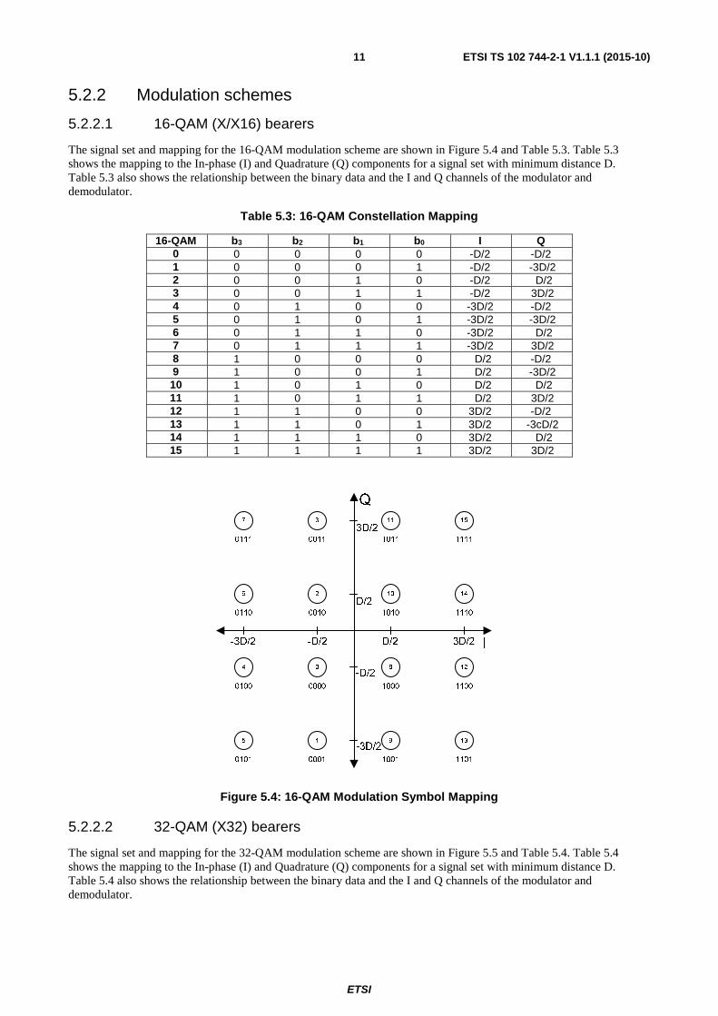
The signal set and mapping for the 16-QAM modulation scheme are shown in Figure 5.4 and Table 5.3. Table 5.3 shows the mapping to the In-phase (I) and Quadrature (Q) components for a signal set with minimum distance D. Table 5.3 also shows the relationship between the binary data and the I and Q channels of the modulator and demodulator.
Table 5.3: 16-QAM Constellation Mapping
16-QAM b3 b2 b1 b0 I Q 0 0 0 0 0 -D/2 -D/2 1 0 0 0 1 -D/2 -3D/2 2 0 0 1 0 -D/2 D/2 3 0 0 1 1 -D/2 3D/2 4 0 1 0 0 -3D/2 -D/2 5 0 1 0 1 -3D/2 -3D/2 6 0 1 1 0 -3D/2 D/2 7 0 1 1 1 -3D/2 3D/2 8 1 0 0 0 D/2 -D/2 9 1 0 0 1 D/2 -3D/2 10 1 0 1 0 D/2 D/2 11 1 0 1 1 D/2 3D/2 12 1 1 0 0 3D/2 -D/2 13 1 1 0 1 3D/2 -3cD/2 14 1 1 1 0 3D/2 D/2 15 1 1 1 1 3D/2 3D/2
Figure 5.4: 16-QAM Modulation Symbol Mapping
5.2.2.2 32-QAM (X32) bearers
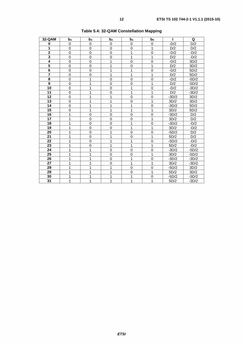
The signal set and mapping for the 32-QAM modulation scheme are shown in Figure 5.5 and Table 5.4. Table 5.4 shows the mapping to the In-phase (I) and Quadrature (Q) components for a signal set with minimum distance D. Table 5.4 also shows the relationship between the binary data and the I and Q channels of the modulator and demodulator.
ETSI
ETSI TS 102 744-2-1 V1.1.1 (2015-10) 12
Table 5.4: 32-QAM Constellation Mapping
32-QAM b4 b3 b2 b1 b0 I Q 0 0 0 0 0 0 -D/2 D/2 1 0 0 0 0 1 D/2 D/2 2 0 0 0 1 0 -D/2 -D/2 3 0 0 0 1 1 D/2 -D/2 4 0 0 1 0 0 -D/2 3D/2 5 0 0 1 0 1 D/2 3D/2 6 0 0 1 1 0 -D/2 5D/2 7 0 0 1 1 1 D/2 5D/2 8 0 1 0 0 0 -D/2 -5D/2 9 0 1 0 0 1 D/2 -5D/2 10 0 1 0 1 0 -D/2 -3D/2 11 0 1 0 1 1 D/2 -3D/2 12 0 1 1 0 0 -3D/2 3D/2 13 0 1 1 0 1 3D/2 3D/2 14 0 1 1 1 0 -3D/2 5D/2 15 0 1 1 1 1 3D/2 5D/2 16 1 0 0 0 0 -3D/2 D/2 17 1 0 0 0 1 3D/2 D/2 18 1 0 0 1 0 -3D/2 -D/2 19 1 0 0 1 1 3D/2 -D/2 20 1 0 1 0 0 -5D/2 D/2 21 1 0 1 0 1 5D/2 D/2 22 1 0 1 1 0 -5D/2 -D/2 23 1 0 1 1 1 5D/2 -D/2 24 1 1 0 0 0 -3D/2 -5D/2 25 1 1 0 0 1 3D/2 -5D/2 26 1 1 0 1 0 -3D/2 -3D/2 27 1 1 0 1 1 3D/2 -3D/2 28 1 1 1 0 0 -5D/2 3D/2 29 1 1 1 0 1 5D/2 3D/2 30 1 1 1 1 0 -5D/2 -3D/2 31 1 1 1 1 1 5D/2 -3D/2

ETSI
ETSI TS 102 744-2-1 V1.1.1 (2015-10) 13
Figure 5.5: 32-QAM Modulation Symbol Mapping
5.2.2.3 64-QAM (X64) bearers
The signal set and mapping for the 64-QAM modulation scheme are shown in Figure 5.6 and Table 5.5. Table 5.5 shows the mapping to the In-phase (I) and Quadrature (Q) components for a signal set with minimum distance D. The table also shows the relationship between the binary data and the I and Q channels of the modulator and demodulator.
Table 5.5: 64-QAM Constellation Mapping
64-QAM b5 b4 b3 b2 b1 b0 I Q 0 0 0 0 0 0 0 3D/2 3D/2 1 0 0 0 0 0 1 3D/2 D/2 2 0 0 0 0 1 0 3D/2 5D/2 3 0 0 0 0 1 1 3D/2 7D/2 4 0 0 0 1 0 0 3D/2 -3D/2 5 0 0 0 1 0 1 3D/2 -D/2 6 0 0 0 1 1 0 3D/2 -5D/2 7 0 0 0 1 1 1 3D/2 -7D/2 8 0 0 1 0 0 0 D/2 3D/2 9 0 0 1 0 0 1 D/2 D/2
10 0 0 1 0 1 0 D/2 5D/2 11 0 0 1 0 1 1 D/2 7D/2 12 0 0 1 1 0 0 D/2 -3D/2 13 0 0 1 1 0 1 D/2 -D/2 14 0 0 1 1 1 0 D/2 -5D/2
12 4
0
18 2
26 10
5 13
171
3
2711
19
16
I
Q
-5D/2 -3D/2 -D/2 D/2 3D/2 5D/2
3D/2
D/2
-D/2
-3D/2
00000
20
28
14 6 7 15
29
21
23
31
259824
22
30
5D/2
-5D/2
00001
00010 00011
00100 00101
00110 00111
01000 01001
01010 01011
01100 01101
01110 01111
10000 10001
10010 10011
10100 10101
10110 10111
11000 11001
11010 11011
11100 11101
11110 11111

ETSI
ETSI TS 102 744-2-1 V1.1.1 (2015-10) 14
64-QAM b5 b4 b3 b2 b1 b0 I Q 15 0 0 1 1 1 1 D/2 -7D/2 16 0 1 0 0 0 0 5D/2 3D/2 17 0 1 0 0 0 1 5D/2 D/2 18 0 1 0 0 1 0 5D/2 5D/2 19 0 1 0 0 1 1 5D/2 7D/2 20 0 1 0 1 0 0 5D/2 -3D/2 21 0 1 0 1 0 1 5D/2 -D/2 22 0 1 0 1 1 0 5D/2 -5D/2 23 0 1 0 1 1 1 5D/2 -7D/2 24 0 1 1 0 0 0 7D/2 3D/2 25 0 1 1 0 0 1 7D/2 D/2 26 0 1 1 0 1 0 7D/2 5D/2 27 0 1 1 0 1 1 7D/2 7D/2 28 0 1 1 1 0 0 7D/2 -3D/2 29 0 1 1 1 0 1 7D/2 -D/2 30 0 1 1 1 1 0 7D/2 -5D/2 31 0 1 1 1 1 1 7D/2 -7D/2 32 1 0 0 0 0 0 -3D/2 3D/2 33 1 0 0 0 0 1 -3D/2 D/2 34 1 0 0 0 1 0 -3D/2 5D/2 35 1 0 0 0 1 1 -3D/2 7D/2 36 1 0 0 1 0 0 -3D/2 -3D/2 37 1 0 0 1 0 1 -3D/2 -D/2 38 1 0 0 1 1 0 -3D/2 -5D/2 39 1 0 0 1 1 1 -3D/2 -7D/2 40 1 0 1 0 0 0 -D/2 3D/2 41 1 0 1 0 0 1 -D/2 D/2 42 1 0 1 0 1 0 -D/2 5D/2 43 1 0 1 0 1 1 -D/2 7D/2 44 1 0 1 1 0 0 -D/2 -3D/2 45 1 0 1 1 0 1 -D/2 -D/2 46 1 0 1 1 1 0 -D/2 -5D/2 47 1 0 1 1 1 1 -D/2 -7D/2 48 1 1 0 0 0 0 -5D/2 3D/2 49 1 1 0 0 0 1 -5D/2 D/2 50 1 1 0 0 1 0 -5D/2 5D/2 51 1 1 0 0 1 1 -5D/2 7D/2 52 1 1 0 1 0 0 -5D/2 -3D/2 53 1 1 0 1 0 1 -5D/2 -D/2 54 1 1 0 1 1 0 -5D/2 -5D/2 55 1 1 0 1 1 1 -5D/2 -7D/2 56 1 1 1 0 0 0 -7D/2 3D/2 57 1 1 1 0 0 1 -7D/2 D/2 58 1 1 1 0 1 0 -7D/2 5D/2 59 1 1 1 0 1 1 -7D/2 7D/2 60 1 1 1 1 0 0 -7D/2 -3D/2 61 1 1 1 1 0 1 -7D/2 -D/2 62 1 1 1 1 1 0 -7D/2 -5D/2 63 1 1 1 1 1 1 -7D/2 -7D/2

ETSI
ETSI TS 102 744-2-1 V1.1.1 (2015-10) 15
Figure 5.6: 64-QAM Modulation Symbol Mapping
5.2.2.4 QPSK (Q/X4) bearers
The signal set and mapping for the QPSK modulation scheme are shown in Figure 5.7 and Table 5.6. Table 5.6 shows the mapping to the In-phase (I) and Quadrature (Q) components for a signal set with minimum distance D. Table 5.6 also shows the relationship between the binary data and the I and Q channels of the modulator and demodulator.
Table 5.6: QPSK Constellation Mapping
QPSK b1 b0 I Q 0 0 0 D/2 D/2 1 0 1 D/2 -D/2 2 1 0 -D/2 D/2 3 1 1 -D/2 -D/2
32 40
41
37 45
36 44
8 0
19
13
412
5
33
I
Q
-7D/2 -5D/2 -3D/2 -D/2 D/2 3D/2 5D/2 7D/2
3D/2
D/2
-D/2
-3D/2
49
48
34 42 10 2
16
17
21
20
6144638
53
52
5D/2
-5D/2
000000
51
5058
59
54
5563
62 30
3123
22
27
2618
1935
39 7
31143
1547
29
28
24
25
56
57
61
60
000001
000010
000011
000100
000101
000110
000111
001000
001001
001010
001011
001100
001101
001110
001111
010000
010001
010010
010011
010100
010101
010110
010111
011000
011001
011010
011011
011100
011101
011110
011111
100000
100001
100010
100 011
100100
100101
100110
100111
101000
101001
101010
101011
101100
101101
101110
101111
110000
110001
110010
110 011
110100
110101
110110
110111
111000
111001
111010
111011
111100
111101
111110
111111
7D/2
-7D/2

ETSI
ETSI TS 102 744-2-1 V1.1.1 (2015-10) 16
Figure 5.7: QPSK Modulation Symbol Mapping
In order to normalize the average symbol power to 1, the inter-symbol distance D is presented in Table 5.7.
Table 5.7: Inter-symbol distance D for modulation schemes
Modulation Scheme
D
Q/X4 2 x (2)-0.5 X/X16 2 x (10)-0.5 X32 2 x (20)-0.5 X64 2 x (42)-0.5
5.2.2.5 Dynamic Modulation
In addition to different coding rates on an FEC block basis, the forward transmit channel units shall be able to dynamically change the modulation on an FEC block basis. Dynamic modulation shall be performed as directed by the Bearer Control Layer to adapt transmission to different UE types for the following forward bearers, as shown in Table 5.8.
Table 5.8: Dynamic Modulation
Bearer Dynamic Modulation FR80T2.5X4/16 QPSK and 16-QAM FR80T5X4/16 QPSK and 16-QAM
When dynamic modulation is applied, the first FEC block shall always be modulated as QPSK (see ETSI TS 102 744-3-2 [4]).
Forward Frames using dynamic modulation are signalled as FbearerType = f80t25x4-5b (5) for FR80T2.5X4/16-5B or FbearerType = f80t5x4-9b (9) for FR80T5X4/16-9B. The Unique word shall indicate the coding rate of the first FEC Block which is always using QPSK (X4) modulation with coding rates in the range L8 to L3. Any dynamic change to another code rate or 16 QAM (X16) modulation is signalled to the UEs using the ForwardBearerCodeRate BCtAVP (ETSI TS 102 744-3-1 [3]). In FEC blocks where 16 QAM (X16) is used, the coding rates are restricted to L2 - H6.
5.2.3 Channel filtering
The forward channel modulator shall use a root-raised-cosine (RRC) filter function for symbol shaping. The demodulator shall use same RRC filter for matched filter reception. The filter function roll-off shall be 0,25 for all the bearers, except for the family of FR80T2.5 and FR80T5 bearers where the filter function roll-off shall be 0,13. The frequency masks are derived from the impulse response specified in Equation 1 - RRC impulse response.

ETSI
ETSI TS 102 744-2-1 V1.1.1 (2015-10) 17
(1)
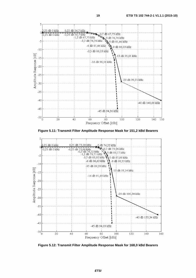
where R is the filter roll-off factor and T is the symbol period. The resulting shaped modulation spectrums shall comply with the frequency masks. The frequency masks for the forward bearer symbol rates are shown in Figures 5.8, 5.9, 5.10, 5.11 and 5.12.
NOTE: The plots do not take HPA distortion into account, they only illustrate the modulator characteristics.
Figure 5.8: Transmit Filter Amplitude Response Mask for 8,4 kBd Bearers
( ) ( )
⎟⎟⎟⎟
⎠
⎞
⎜⎜⎜⎜
⎝
⎛⎟⎠
⎞⎜⎝
⎛ ⋅⋅+⋅⋅+
⋅⋅
⎟⎠
⎞⎜⎝
⎛ ⋅⋅−⋅
⋅⋅⋅−=
π
π
π
πT
tRR
Tt
T
tR
TtR
th1cos4
1
1sin
1161
1)(
222

ETSI
ETSI TS 102 744-2-1 V1.1.1 (2015-10) 18
Figure 5.9: Transmit Filter Amplitude Response Mask for 33,6 kBd Bearers
Figure 5.10: Transmit Filter Amplitude Response Mask for 84,0 kBd Bearers
ETSI
ETSI TS 102 744-2-1 V1.1.1 (2015-10) 19
Figure 5.11: Transmit Filter Amplitude Response Mask for 151,2 kBd Bearers
Figure 5.12: Transmit Filter Amplitude Response Mask for 168,0 kBd Bearers

ETSI
ETSI TS 102 744-2-1 V1.1.1 (2015-10) 20
The total modulator delay distortion shall be within the mask in Figure 5.13.
Figure 5.13: Delay Distortion Mask
The values of 'A' and 'B' in Figure 5.13 depend on the used bearer type and are specified in Table 5.9.
Table 5.9: Values of 'A' and 'B' in Figure 5.13 vs. Bearer Symbol Rate
Bearer Symbol Rate (kBd)
'A' Maximum Frequency
Offset (kHz)
'B' Maximum Group
Delay Distortion (μs) 8,4 ± 5,25 ± 10,0
33,6 ± 21,00 ± 2,5 84,0 ± 47,46 ± 1,0
151,2 ± 94,50 ± 0,5 168,0 ± 94,92 ± 0,5
5.3 Bearer types and frame formats
5.3.1 Frame numbering
On the forward link, the 80 ms frames are numbered using a 12 bit unsigned integer. After frame 4 095 the frame number wraps around to zero. The frame number is included in the Bulletin Board SDU (see ETSI TS 102 744-3-1 [3]), which is transmitted at regular intervals on each forward bearer.
5.3.2 Forward bearer parameters
Each of the main bearer types listed in clause 5.1 can support a range of bearer sub-types that correspond to different FEC coding rates as detailed in clause B.1.
These different bearer sub-types are used for forward link adaptation to optimize the coding rate for the prevailing channel conditions. Refer to the Bearer Control Operation (ETSI TS 102 744-3-2 [4]) for more details.

ETSI
ETSI TS 102 744-2-1 V1.1.1 (2015-10) 21
5.3.3 Forward channel frame formats
The frame format is based on a frame duration of 80 ms. The main frame parameters for each bearer type are listed in Table 5.10.
Table 5.10: Frame Parameters for Forward Link Bearers
Bearer Type Identifier (Note)
Slot Duration
(ms)
Modulator Output
Symbols (MOS)
Start UW Symbols
Pilot Symbols
(PS)
Data Symbols
(DS)
Turbo Encoded Output
(TEO)(symbols/ block)
FEC Blocks
per Frame
(N)
Total Encoded Symbols
per Frame
F80T0.25Q-1B 80 672 40 88 6 544 1 544 F80T1Q-1B 80 2 688 40 88 29 2 560 1 2 560 F80T1Q-4B 80 2 688 40 88 29 640 4 2 560 F80T1X-4B 80 2 688 40 88 29 640 4 2 560 FR80T2.5X4/16-5B 80 6 720 40 90 73 1 318 5 6 590 FR80T2.5X16-5B 80 6 720 40 90 73 1 318 5 6 590 FR80T2.5X32-6B 80 6 720 40 92 71 1 098 6 6 588 FR80T2.5X64-7B 80 6 720 40 93 70 941 7 6 587 F80T4.5X-8B 80 12 096 40 88 136 1 496 8 11 968 FR80T5X4/16-9B 80 13 440 40 89 149 1 479 9 13 311 FR80T5X16-9B 80 13 440 40 89 149 1 479 9 13 311 FR80T5X32-11B 80 13 440 40 90 147 1 210 11 13 310 FR80T5X64-13B 80 13 440 40 88 151 1 024 13 13 312 NOTE: The bearer type identifier notation used in the present document is defined in Annex A.
Each frame is divided into a number of subframes (FEC blocks) as illustrated in Figure 5.14.
Figure 5.14: Generic Frame Format for Forward Channel
The detailed parameters are dependent on the bearer type and the coding scheme. The nomenclature in Figure 5.14 is defined as follows:
• Modulator Output Symbols: MOS is defined as the total symbols at the output of the QPSK/QAM modulator with reference to a 80 ms frame. These symbols have been modulated, interleaved and then inserted with modulated PSs/UW in the 80 ms frame.
• Pilot Symbols: PS is defined as the total number of pilot symbols transmitted in the frame.
• Data Symbols: DS is defined as the total number of data symbols between 2 consecutive pilot symbols.
• Turbo Encoded Output: TEO is defined as the total number of encoded symbols per FEC block at the output of the turbo encoder.

ETSI
ETSI TS 102 744-2-1 V1.1.1 (2015-10) 22
• FEC Block Number: N is the total number of FEC blocks per frame.
For the FR80T2.5 and FR80T5 family of bearers, a CW of 10 symbols and 20 symbols respectively (0,12 ms duration) shall be present in the first frame only. This is to ensure HPA power control at the beginning of the frame. The first symbol of the UW shall be used for CW.
5.3.4 Unique words
5.3.4.0 General
Different Unique Words are used to signal the coding level being applied to the first FEC block in the 80 ms frame. The coding level of the subsequent blocks (if different from the one used in the first block) shall be signalled in a Bearer Control AVP (see ETSI TS 102 744-3-1 [3]). The Unique Words that shall be used for all bearers are specified in Figure 5.15.
Figure 5.15: Forward Bearer Unique Words (in hexadecimal)
The inter-symbol spacing for the UWs is specified in the following clauses. Unique Words are not FEC coded and not scrambled.
5.3.4.1 QPSK (Q) bearers
The mapping of the Unique Words onto the QPSK symbols shall be as shown in Figure 5.16.
Figure 5.16: QPSK Bearer Unique Word Symbol Mapping
F80X/Q UWL8 E 4 5 6 4 A D A B DL7 B E D 8 B 3 E A D 2L6 F 2 F 5 F 4 9 6 A 6L5 C 9 1 1 3 6 4 2 8 AL4 F 9 A 4 2 B B 1 A BL3 D 4 E 3 5 7 2 9 9 CL2 4 C B 9 D 9 D 1 7 4L1 6 A A F 7 A 6 E 4 ER C 2 4 0 E 9 6 5 8 7H1 5 1 4 B B 8 B A 6 2H2 B 5 8 9 6 C C D D FH3 A 8 7 B 0 D A 6 C 9H4 5 A 1 A 6 7 9 D 6 FH5 6 1 F E A 5 4 9 4 3H6 A 3 2 A D 2 8 1 C 4

ETSI
ETSI TS 102 744-2-1 V1.1.1 (2015-10) 23
5.3.4.2 X (F80T1X, F80T4.5X) Bearers
The mapping of the Unique Words onto the 16-QAM symbols for the F80T1X-4B and F80T4.5X-8B shall be as shown in Figure 5.17.
Figure 5.17: 16-QAM (X) Bearer Unique Word Symbol Mapping
5.3.4.3 X4/16 (FR80T2.5X4/16-5B, FR80T5X4/16-9B) Bearers
The Unique Words for X4/16 bearers shall be as shown in Figure 5.18.
Figure 5.18: X4/16 Bearer Unique Word Symbol Mapping (Relative to QPSK FEC block symbols)
ETSI
ETSI TS 102 744-2-1 V1.1.1 (2015-10) 24
The Unique Words for X4/16 bearers are shown relative to 16-QAM FEC blocks in Figure 5.19.
Figure 5.19: X4/16 Bearer Unique Word Symbol Mapping relative to 16-QAM FEC blocks
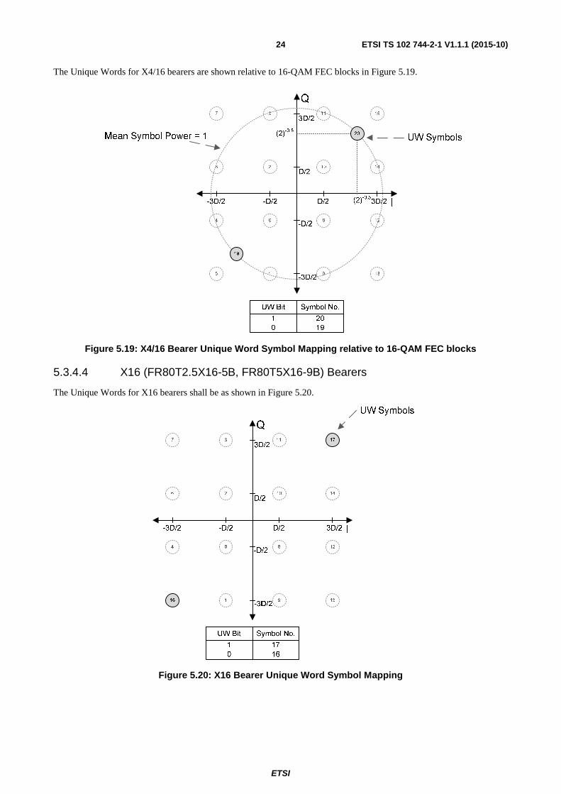
5.3.4.4 X16 (FR80T2.5X16-5B, FR80T5X16-9B) Bearers
The Unique Words for X16 bearers shall be as shown in Figure 5.20.
Figure 5.20: X16 Bearer Unique Word Symbol Mapping

ETSI
ETSI TS 102 744-2-1 V1.1.1 (2015-10) 25
5.3.4.5 X32 (FR80T2.5X32-6B, FR80T5X32-11B) Bearers
The Unique Words for X32 bearers shall be as shown in Figure 5.21.
Figure 5.21: X32 Bearer Unique Word Symbol Mapping
ETSI
ETSI TS 102 744-2-1 V1.1.1 (2015-10) 26
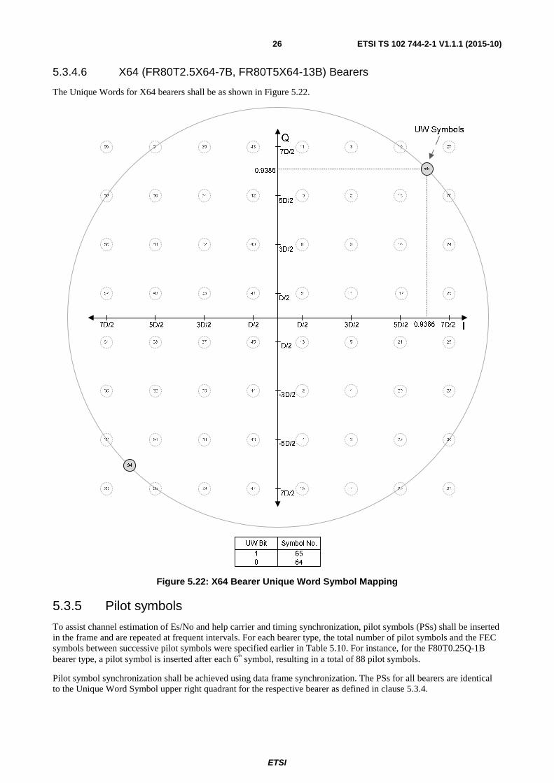
5.3.4.6 X64 (FR80T2.5X64-7B, FR80T5X64-13B) Bearers
The Unique Words for X64 bearers shall be as shown in Figure 5.22.
Figure 5.22: X64 Bearer Unique Word Symbol Mapping
5.3.5 Pilot symbols
To assist channel estimation of Es/No and help carrier and timing synchronization, pilot symbols (PSs) shall be inserted in the frame and are repeated at frequent intervals. For each bearer type, the total number of pilot symbols and the FEC symbols between successive pilot symbols were specified earlier in Table 5.10. For instance, for the F80T0.25Q-1B bearer type, a pilot symbol is inserted after each 6th symbol, resulting in a total of 88 pilot symbols.
Pilot symbol synchronization shall be achieved using data frame synchronization. The PSs for all bearers are identical to the Unique Word Symbol upper right quadrant for the respective bearer as defined in clause 5.3.4.

ETSI
ETSI TS 102 744-2-1 V1.1.1 (2015-10) 27
5.3.6 Empty block data
In the case where there is no data to be transmitted in a FEC-block, an All-zero data vector shall be transmitted. This all-zero data-vector shall be scrambled by the data scrambler defined in clause 5.3.7. The code-rate of the empty FEC-block shall follow the same rules as for FEC-blocks containing normal PDUs.
5.3.7 Scrambling
Scrambling is applied to all FEC blocks. The scrambler is initialized at the start of each FEC block.
A pseudo-noise (PN) scrambler with a 15-stage shift register is used for scrambling before FEC encoding. The scrambler configuration is shown in Figure 5.23. The polynomial for the h-register of the scrambler is 1 + X + X15. The scrambler is clocked at the rate of one shift per information bit, with the first bit into the scrambler at the beginning of each frame being "Exclusive-Or" combined with the output of the scrambler shift generator corresponding to the initial-state scrambling vector. The initial state of the shift register is set to the default value of 110 1001 0101 1001 (6959h). Unique Words and Pilot Symbols are not scrambled.
The descrambler configuration is the same as that for the scrambler.
Figure 5.23: Scrambler and Descrambler Configuration
5.3.8 Coding
5.3.8.0 General
Clauses 5.3.8.1 to 5.3.8.5 apply to all FEC blocks.
5.3.8.1 Turbo coding
The FEC coding used is Turbo coding. The turbo encoder consists of a buffer, an S-type interleaver, two identical 16-state Systematic Recursive Convolution Code (SRCC) encoders and a puncturer and is constructed as shown in Figure 5.24. The sizes of the buffer and the S-interleaver are identical and equal to the turbo code block size. The output data set from the puncturer is mapped into a 16/32/64 QAM or QPSK constellation.
Figure 5.24: Turbo-Encoder Block Diagram

ETSI
ETSI TS 102 744-2-1 V1.1.1 (2015-10) 28
The physical layer allows for a set of puncturing matrices to be used, thus making the coding rate variable. The lowest coding rate can be 1/3, while the highest rate can be very close to one.
5.3.8.2 SRCC encoder
The SRCC encoder is shown in Figure 5.25.
Figure 5.25: SRCC Encoder
The backward polynomial is 23 in octal, and the forward polynomial is 35 in octal:
Backward Polynomial: 1 + X3 + X4
Forward Polynomial: 1 + X + X2 + X4
It is important to note that the two SRCC encoders are set to the zero state at the beginning of each turbo code block (FEC block). The encoder shown in the upper half of Figure 5.24 (with output signals p and d) is in the following text referred to as the 'un-interleaved encoder' while the other encoder (output signals q and nc) is referred to as the 'interleaved encoder'.
The un-interleaved SRCC encoder is flushed, ensuring that its end-state is zero (0,0,0,0). This is accomplished by following the procedure below:
1) All data bits are pushed through the un-interleaved encoder. The end state of the encoder determines the 4 flush bits, which needs to be appended to the data bits. The encoder state is the contents of the delay elements of Figure 5.25 as read from left to right, i.e. the encoder state 0001 corresponds to a 1 in the rightmost delay element.
2) The flush bits are chosen from Table 5.11, according to the end state.
3) These bits are then pushed through the un-interleaved encoder to insure it ends up in state zero (0,0,0,0).
4) The flush bits are also appended to the interleaver input, and interleaved with the data. All bits are then pushed through the interleaved encoder. Because the data bits are interleaved and the flush bits are interleaved with them, the end state of the interleaved encoder is unknown.
ETSI
ETSI TS 102 744-2-1 V1.1.1 (2015-10) 29
Table 5.11: Flush Bits as a Function of the Final State (after Information Bits) of the Un-Interleaved Encoder
Coder State Flush Bits 0000 0 0 0 0 0001 1 0 0 0 0010 1 1 0 0 0011 0 1 0 0 0100 0 1 1 0 0101 1 1 1 0 0110 1 0 1 0 0111 0 0 1 0 1000 0 0 1 1 1001 1 0 1 1 1010 1 1 1 1 1011 0 1 1 1 1100 0 1 0 1 1101 1 1 0 1 1110 1 0 0 1 1111 0 0 0 1
The flush bits in Table 5.11 are inserted from left to right as well, i.e. for an encoder state of 0001, a '1' is inserted first and then a sequence of three '0'.
5.3.8.3 S-Interleaver
The interleaving for the physical layer has been optimized for each forward bearer type and sub type. Therefore there are a large number of different interleaver matrices.
The turbo code interleaver matrices for the forward bearers are defined in clause C.1.
5.3.8.4 Puncturing, Channel Interleaving and Symbol Mapping
Puncturing, channel interleaving and symbol mapping is different and optimized for each forward bearer type and sub type. Therefore there are a large number of different matrices.
The puncturing, channel interleaving and symbol mappings for the forward bearers are defined in clause C.2.
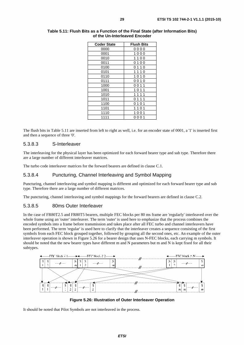
5.3.8.5 80ms Outer Interleaver
In the case of FR80T2.5 and FR80T5 bearers, multiple FEC blocks per 80 ms frame are 'regularly' interleaved over the whole frame using an 'outer' interleaver. The term 'outer' is used here to emphasize that the process combines the encoded symbols into a frame before transmission and takes place after all FEC turbo and channel interleavers have been performed. The term 'regular' is used here to clarify that the interleaver creates a sequence consisting of the first symbols from each FEC block grouped together, followed by grouping all the second ones, etc. An example of the outer interleaver operation is shown in Figure 5.26 for a bearer design that uses N-FEC blocks, each carrying m symbols. It should be noted that the new bearer types have different m and N parameters but m and N is kept fixed for all their subtypes.
Figure 5.26: Illustration of Outer Interleaver Operation
It should be noted that Pilot Symbols are not interleaved in the process.
FEC block # 1 FEC block # 2 FEC block # N
S
1
S
2
S
m
S
1
S
2
S
m
S
1
S
2
S
m
S
1
S
1
S
1
S
2
S
2
S
2
S
m
S
m
S
m

ETSI
ETSI TS 102 744-2-1 V1.1.1 (2015-10) 30
5.4 PDU formats PDUs on the forward link are grouped into a block structure of variable length depending on the bearer type and subtype being used. The block structure consists of a sequence of Forward Bearer Control PDUs (BCt-PDU) followed by padding with zeros, if required, to fill the rest of the FEC block, as defined below and in Table 5.12, and as shown in Figure 5.27.
FwdBlock ::= SEQUENCE {
bpduseq SEQUENCE (SIZE (0..k) OF BCt_PDU,
fill OCTET STRING (SIZE (0..n)) OPTIONAL }
Table 5.12: PDU parameters
Parameter Description bpduseq A sequence of between 0 and k variable length Bearer Control PDUs.
Fill Zero padding used to fill out the block (frame is scrambled in channel unit). There may be between 0 and n bytes of pad depending on the overall length and other information in the block.
Figure 5.27: Forward block structure
The MSB (Bit 8) of octet 1 goes into the scrambler and FEC encoder first and the LSB (Bit 1) of octet n last. The BCt-PDUs are described in detail in ETSI TS 102 744-3-1 [3].
Fill
Octet n
Octet 2
Bits: Octet 1
1 2 3 4 5 6 7 8
BCt_PDU n
BCt_PDU 2
BCt_PDU 1
ETSI
ETSI TS 102 744-2-1 V1.1.1 (2015-10) 31
6 Return bearers
6.1 Introduction
6.1.1 Return bearer types
The return bearers are capable of carrying nominal data rates in the range between 3,2 kbit/s and 848,0 kbit/s and are based upon two transmission strategies, burst and continuous using a Time-Division-Multiple Access Scheme (TDMA).
Clause 6.3 describes the physical attributes of the return bearer types, and the general UE and RNS requirements when operating with these bearer types. The TDMA nature of these bearers requires certain transmission timing protocols and algorithms, which are described in clause 6.5.
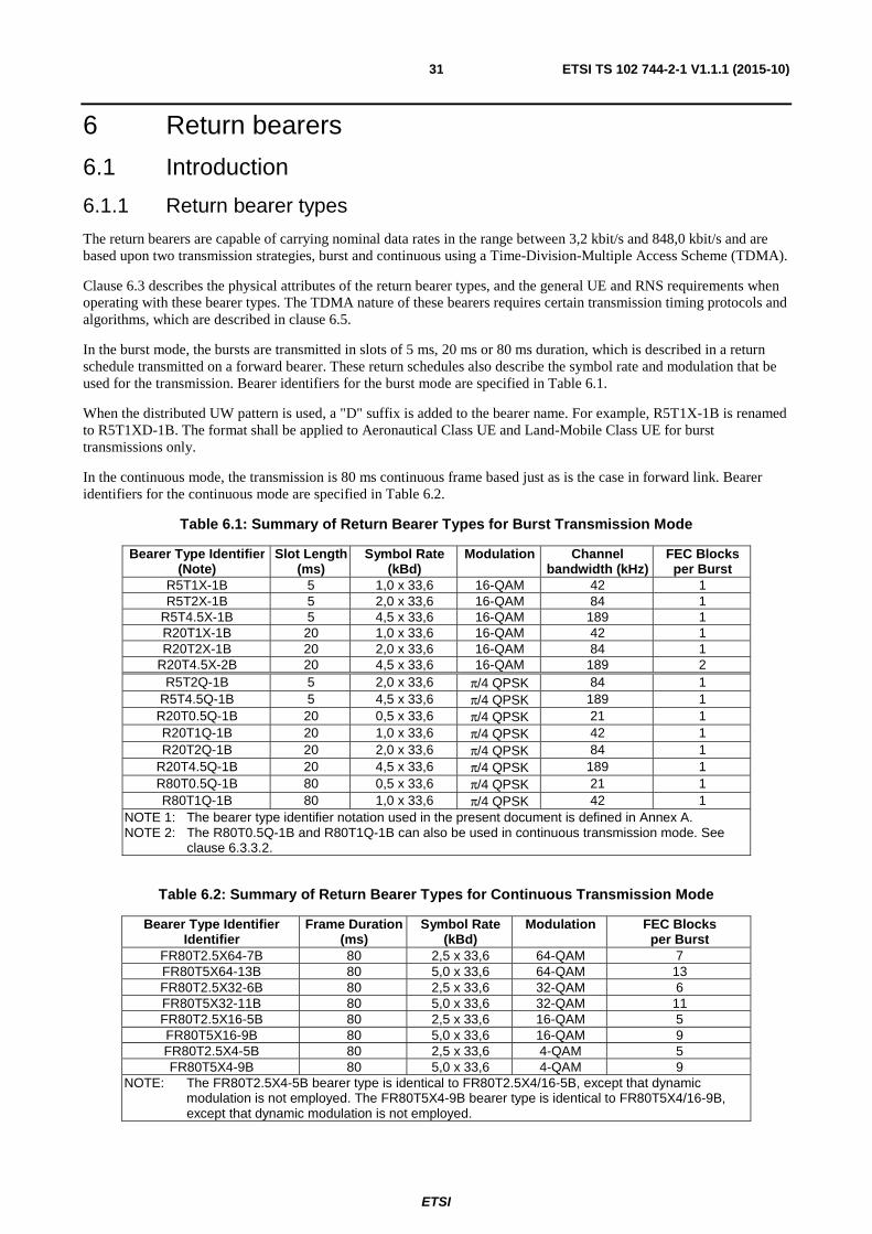
In the burst mode, the bursts are transmitted in slots of 5 ms, 20 ms or 80 ms duration, which is described in a return schedule transmitted on a forward bearer. These return schedules also describe the symbol rate and modulation that be used for the transmission. Bearer identifiers for the burst mode are specified in Table 6.1.
When the distributed UW pattern is used, a "D" suffix is added to the bearer name. For example, R5T1X-1B is renamed to R5T1XD-1B. The format shall be applied to Aeronautical Class UE and Land-Mobile Class UE for burst transmissions only.
In the continuous mode, the transmission is 80 ms continuous frame based just as is the case in forward link. Bearer identifiers for the continuous mode are specified in Table 6.2.
Table 6.1: Summary of Return Bearer Types for Burst Transmission Mode
Bearer Type Identifier (Note)
Slot Length (ms)
Symbol Rate (kBd)
Modulation Channel bandwidth (kHz)
FEC Blocks per Burst
R5T1X-1B 5 1,0 x 33,6 16-QAM 42 1 R5T2X-1B 5 2,0 x 33,6 16-QAM 84 1
R5T4.5X-1B 5 4,5 x 33,6 16-QAM 189 1 R20T1X-1B 20 1,0 x 33,6 16-QAM 42 1 R20T2X-1B 20 2,0 x 33,6 16-QAM 84 1
R20T4.5X-2B 20 4,5 x 33,6 16-QAM 189 2 R5T2Q-1B 5 2,0 x 33,6 π/4 QPSK 84 1
R5T4.5Q-1B 5 4,5 x 33,6 π/4 QPSK 189 1 R20T0.5Q-1B 20 0,5 x 33,6 π/4 QPSK 21 1 R20T1Q-1B 20 1,0 x 33,6 π/4 QPSK 42 1 R20T2Q-1B 20 2,0 x 33,6 π/4 QPSK 84 1
R20T4.5Q-1B 20 4,5 x 33,6 π/4 QPSK 189 1 R80T0.5Q-1B 80 0,5 x 33,6 π/4 QPSK 21 1 R80T1Q-1B 80 1,0 x 33,6 π/4 QPSK 42 1
NOTE 1: The bearer type identifier notation used in the present document is defined in Annex A. NOTE 2: The R80T0.5Q-1B and R80T1Q-1B can also be used in continuous transmission mode. See
clause 6.3.3.2.
Table 6.2: Summary of Return Bearer Types for Continuous Transmission Mode
Bearer Type Identifier Identifier
Frame Duration (ms)
Symbol Rate (kBd)
Modulation FEC Blocks per Burst
FR80T2.5X64-7B 80 2,5 x 33,6 64-QAM 7 FR80T5X64-13B 80 5,0 x 33,6 64-QAM 13 FR80T2.5X32-6B 80 2,5 x 33,6 32-QAM 6 FR80T5X32-11B 80 5,0 x 33,6 32-QAM 11 FR80T2.5X16-5B 80 2,5 x 33,6 16-QAM 5 FR80T5X16-9B 80 5,0 x 33,6 16-QAM 9 FR80T2.5X4-5B 80 2,5 x 33,6 4-QAM 5 FR80T5X4-9B 80 5,0 x 33,6 4-QAM 9
NOTE: The FR80T2.5X4-5B bearer type is identical to FR80T2.5X4/16-5B, except that dynamic modulation is not employed. The FR80T5X4-9B bearer type is identical to FR80T5X4/16-9B, except that dynamic modulation is not employed.

ETSI
ETSI TS 102 744-2-1 V1.1.1 (2015-10) 32
The channel unit configuration for the return transmitter is shown in Figure 6.1.
Figure 6.1: Transmit Channel Unit Configuration for Return Bearer Types
The return channel modulator shall be able to accommodate flexible channel configurations within a 200 kHz bandwidth, requiring it to be able to switch between different symbol rates, modulation schemes and coding rates on a burst-by-burst basis as directed through Return Schedules transmitted from the RNS.
The receive channel unit shall be able to demodulate a large range of defined return bursts as well as continuous transmissions. For the burst mode, the individual bursts will arrive on a shared access bearer from different transmitters. Therefore no correlation between consecutive bursts can be assumed. For the case of continuous transmission mode, correlation amongst successive transmissions can be assumed. The channel unit configuration for a receiver is shown in Figure 6.2.
Figure 6.2: Receive Channel Unit Configuration for Return Bearer Types
The return channel demodulator shall have a-priori knowledge of the symbol rate, modulation scheme and timeslot size for each expected burst. These parameters may change on a burst-by-burst basis. Such a scenario is illustrated in Figure 6.3. Furthermore, the return channel demodulator shall be able to determine the coding level of each received burst by analysing the received Unique Word.
Scrambler TX select
and transmit
sync.
Turbo encoder
Frame
timing
Timing correction
Higher
Layers
UW/DUW
table
Burst Data bits
Bearer and coding selection
Empty frame detect
Bearer frequency selection
L-band
Up-converter
To satellite
Channel
interleaving
&
Symbol
mapping
(QPSK &
16/32/64
QAM)
Optional
Outer
Interleaver
Preamble
Generator

ETSI
ETSI TS 102 744-2-1 V1.1.1 (2015-10) 33
Figure 6.3: Illustration of Return Channel Flexibility
6.1.2 L-Band Return Frequency Range
The L-Band return (uplink) frequency ranges used by the satellite radio interface are 1 626,500 MHz to 1 660,500 MHz and 1 668,000 MHz to 1 675,000 MHz.
The return frequency range is divided into a set of contiguous 200 kHz subbands. The nominal position of these subbands is aligned with the edges of the band, as illustrated in Figure 6.4.
The centre frequency of each subband is offset from this nominal 200 kHz grid as shown: this offset is referred to as the "subband centre frequency offset" and has a default value of 100 kHz. For example, the lowest nominal subband extends from 1 626,500 MHz to 1 626,700 MHz and has a centre frequency of 1 626,600 MHz.
NOTE: This division into subbands is designed to support the assignment of satellite transponder bandwidth in multiples of 200 kHz.
NOTE: The figure illustrates the subband alignment for the lower of the two L-band uplink allocations, for which the lower boundary of the frequency range is 1 626,500 MHz and the upper boundary is 1 660,500 MHz. The same figure applies for the upper of the two L-band uplink allocations, with the start and end frequencies replaced by 1 668,000 MHz and 1 675,000 MHz respectively.
Figure 6.4: Subband Alignment for L-Band Uplink
As on the L-band downlink (see clause 5.1.2) any changes from the default value of 100 kHz shall be signalled to the UEs in the Subband Centre Frequency Offset Bearer Control AVP (see ETSI TS 102 744-3-1 [3]).
The entire L-band uplink consists of two allocations operating on different Subband Centre Frequency Offsets, namely
• 1 626,500 MHz to 1 660,500 MHz with an offset (a) of 100 kHz (default); and
• 1 668,000 MHz to 1 675,000 MHz with no offset (b) (i.e. offset of 0 kHz).

ETSI
ETSI TS 102 744-2-1 V1.1.1 (2015-10) 34
While the offset (a) is the default value and does not need to be signalled, the modified offset (b) shall be signalled to the UE in the Subband Centre Frequency Offset Change Bearer Control AVP (see ETSI TS 102 744-3-1 [3]).
The centre frequency of a given return bearer is based on a frequency grid of 1,25 kHz, and is signalled to the UEs via the return channel number. When transmitting a return bearer, the UE shall calculate the centre frequency of the appropriate subband using the following formula:
(2)
Where:
FCentreRet is the Centre Frequency of the Return Link Subband (in kHz) Offset is the Subband Centre Frequency Offset (default 100 kHz or as signalled) FRet is the desired return channel frequency (in kHz) floor is a function that returns the integer part of the argument
6.2 Modulation
6.2.1 Symbol rate
The symbol rate used depends on the type of return bearer as shown in Table 6.3.
Table 6.3: Return Bearer Symbol Rates
Bearer Type Identifier Symbol Rate (Bd) R20T0.5Q-1B R80T0.5Q-1B 16,8
R5T1X-1B, R20T1X-1B R20T1Q-1B, R80T1Q-1B 33,6
R5T2X-1B, R20T2X-1B R5T2Q-1B, R20T2Q-1B 67,2
FR80T2.5X4 / X16 / X32 / X64 84,0 R5T4.5X-1B, R20T4.5X-2B R5T4.5Q-1B, R20T4.5Q-1B
151,2
FR80T5X4 / X16 / X32 / X64 168,0
6.2.2 Modulation schemes
6.2.2.1 16-QAM (X) Bearers
Return bearers R5/R20T1X, R5/R20T2X and R5/R20T4.5X use the same 16-QAM modulation scheme as the corresponding forward bearers (see clause 5.2.2).
6.2.2.2 π/4 QPSK Bearers
A π/4 QPSK modulation scheme shall be used for the return bearers, instead of the QPSK modulation scheme used on the forward bearers The symbol mapping is performed by first mapping the bits onto the QPSK map specified in clause 5.2.2. To form the π/4 QPSK modulation, each symbol after the first is rotated counter-clockwise in the complex I/Q plane by π/4 (45 degrees) at every symbol instance. For the case of 5/20 ms bursts, the first symbol is the first CW. For the 80 ms return bursts, the first symbol is the first after the Preamble. The first symbol is always rotated by zero degrees. Figure 6.5 illustrates the transition from QPSK to π/4 QPSK.
][200200
100500 626 1500 626 1 kHz
OffsetFfloorOffsetF
Ret
CentreRet ⎟⎟⎠
⎞⎜⎜⎝
⎛ ⋅⎟⎠
⎞⎜⎝
⎛ +−−++=

ETSI
ETSI TS 102 744-2-1 V1.1.1 (2015-10) 35
Figure 6.5: π/4 QPSK symbol generation
6.2.2.3 FR80T2.5/T5 Bearers
FR80T2.5/T5 bearers in the return direction use the same modulation schemes as the corresponding forward bearers (see clause 5.2.2).
6.2.3 Channel filtering
The return channel filtering shall be identical to the forward channel filtering specified in clause 5.2.3. For return bearers with symbol rates of 33,6 kBd, 84,0 kBd, 151,2 kBd and 168,0 kBd, the frequency masks in Figures 5.8, 5.9, 5.10 and 5.11 respectively shall apply. For return bearers with symbol rates of 16,8 kBd and 67,2 kBd, the frequency masks are shown below in Figures 6.6 and 6.7 respectively.
Figure 6.6: Transmit Modulation Spectrum for 16,8 kBd Bearers
ETSI
ETSI TS 102 744-2-1 V1.1.1 (2015-10) 36
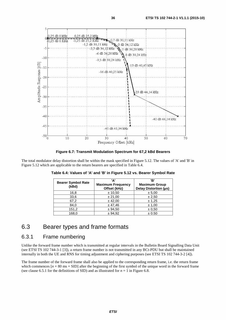
Figure 6.7: Transmit Modulation Spectrum for 67,2 kBd Bearers
The total modulator delay distortion shall be within the mask specified in Figure 5.12. The values of 'A' and 'B' in Figure 5.12 which are applicable to the return bearers are specified in Table 6.4.
Table 6.4: Values of 'A' and 'B' in Figure 5.12 vs. Bearer Symbol Rate
Bearer Symbol Rate (kBd)
'A' Maximum Frequency
Offset (kHz)
'B' Maximum Group
Delay Distortion (μs) 16,8 ± 10,50 ± 5,00 33,6 ± 21,00 ± 2,50 67,2 ± 42,00 ± 1,25 84,0 ± 47,46 ± 1,00
151,2 ± 94,50 ± 0,50 168,0 ± 94,92 ± 0.50
6.3 Bearer types and frame formats
6.3.1 Frame numbering
Unlike the forward frame number which is transmitted at regular intervals in the Bulletin Board Signalling Data Unit (see ETSI TS 102 744-3-1 [3]), a return frame number is not transmitted in any BCt-PDU but shall be maintained internally in both the UE and RNS for timing adjustment and ciphering purposes (see ETSI TS 102 744-3-2 [4]).
The frame number of the forward frame shall also be applied to the corresponding return frame, i.e. the return frame which commences [n × 80 ms + SID] after the beginning of the first symbol of the unique word in the forward frame (see clause 6.5.1 for the definitions of SID) and as illustrated for n = 1 in Figure 6.8.

ETSI
ETSI TS 102 744-2-1 V1.1.1 (2015-10) 37
Figure 6.8: Return Frame and Slot Numbering (Referenced at the UE Antenna)
Each 80 ms return frame is sub-divided into 5 ms slots, which are numbered from 0 to 15. If a 20 ms burst is transmitted, its slot number is equal to the number of the first 5 ms slot which it occupies.
All return channel frame numbering is referenced to the UE antenna. The delay offset between forward frame number and return channel number will obviously be much larger at the RNS demodulators than at the UE due to the round trip delay of the satellite channel.
6.3.2 Return bearer parameters
Each of the main bearer types listed in clause 6.1 can support a range of bearer sub-types that correspond to different FEC coding rates as detailed in clause B.2.
These different bearer sub-types are used for return link adaptation to optimize the coding rate for the prevailing channel conditions. Refer to the Bearer Control Operation (ETSI TS 102 744-3-2 [4]) for more details.
6.3.3 Return channel frame format
6.3.3.0 General
The return link frame format is based on frame duration of 80 ms for the case of continuous transmission and 5/20/80 ms duration for the case of burst format. The 80 ms frame format is same as forward link and has been specified in clause 5.3.3. The burst definitions for 5/20/80 ms slots are specified in the following clauses.
6.3.3.1 5 ms Slot and Burst Definition
The 5 ms bursts are used to carry signalling information between the UE and RNS, and for short data bursts between applications, such as are used for acknowledgements or low bit rate voice codec frames. The 5 ms slots provide capacity for data from the upper layers between 19 octets and 275 octets (depending on the selected bearer type and subtype). The 5 ms slots may be available for random access transmissions by UEs, or may be reserved for use by specific UEs that are in active communication with the RNS.
Frame 0 Frame 1
80 ms 80 ms
Forward :
80 ms 80 msSID : x ms
Frame 4095 Frame 0
0 1 2 3 4 5 6 7 8 910
11
12
13
14
15
5ms
0 1 2 3 4 5 6 7 8 910
11
12
13
14
15
Return :
Burst slot number :
ETSI
ETSI TS 102 744-2-1 V1.1.1 (2015-10) 38
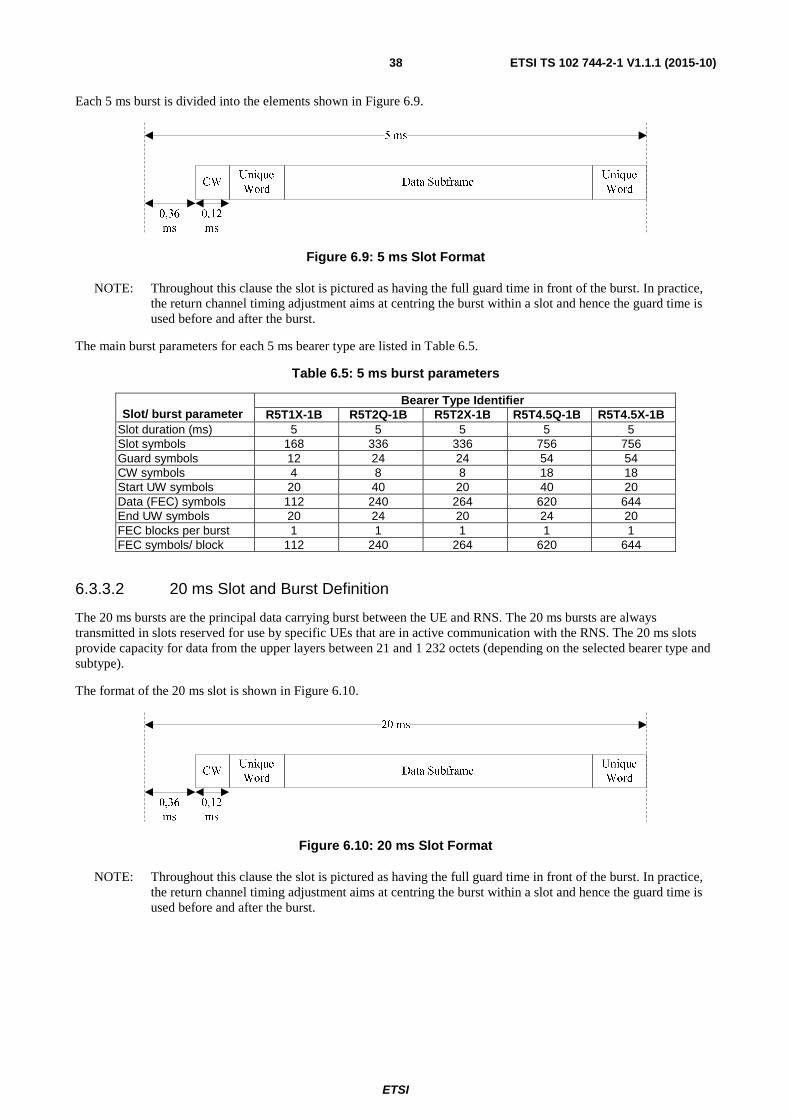
Each 5 ms burst is divided into the elements shown in Figure 6.9.
Figure 6.9: 5 ms Slot Format
NOTE: Throughout this clause the slot is pictured as having the full guard time in front of the burst. In practice, the return channel timing adjustment aims at centring the burst within a slot and hence the guard time is used before and after the burst.
The main burst parameters for each 5 ms bearer type are listed in Table 6.5.
Table 6.5: 5 ms burst parameters
Slot/ burst parameter
Bearer Type Identifier R5T1X-1B R5T2Q-1B R5T2X-1B R5T4.5Q-1B R5T4.5X-1B
Slot duration (ms) 5 5 5 5 5 Slot symbols 168 336 336 756 756 Guard symbols 12 24 24 54 54 CW symbols 4 8 8 18 18 Start UW symbols 20 40 20 40 20 Data (FEC) symbols 112 240 264 620 644 End UW symbols 20 24 20 24 20 FEC blocks per burst 1 1 1 1 1 FEC symbols/ block 112 240 264 620 644
6.3.3.2 20 ms Slot and Burst Definition
The 20 ms bursts are the principal data carrying burst between the UE and RNS. The 20 ms bursts are always transmitted in slots reserved for use by specific UEs that are in active communication with the RNS. The 20 ms slots provide capacity for data from the upper layers between 21 and 1 232 octets (depending on the selected bearer type and subtype).
The format of the 20 ms slot is shown in Figure 6.10.
Figure 6.10: 20 ms Slot Format
NOTE: Throughout this clause the slot is pictured as having the full guard time in front of the burst. In practice, the return channel timing adjustment aims at centring the burst within a slot and hence the guard time is used before and after the burst.

ETSI
ETSI TS 102 744-2-1 V1.1.1 (2015-10) 39
The main burst parameters for each 20 ms bearer type are listed in Table 6.6.
Table 6.6: 20 ms burst parameters
Slot/ burst parameter
Bearer Type Identifier R20T0.5Q-1B R20T1Q-1B R20T1X-1B R20T2Q-1B R20T2X-1B R20T4.5Q-1B R20T4.5X-2B
Slot duration (ms) 20 20 20 20 20 20 20 Slot symbols 336 672 672 1 344 1 344 3 024 3 024 Guard symbols 6 12 12 24 24 54 54 CW symbols 2 4 4 8 8 18 18 Start UW symbols 40 40 40 40 40 40 40 Data (FEC) symbols
264 592 596 1 248 1 252 2 888 2 892
End UW symbols 24 24 20 24 20 24 20 FEC blocks per burst
1 1 1 1 1 1 2
FEC symbols/ block
264 592 596 1 248 1 252 2 888 1 446
NOTE: The R20T0.5Q burst may also be used by the UE for random access in contention slots.
6.3.3.3 80 ms Slot and Burst Definition
6.3.3.3.0 General
The bearers R80T0.5Q-1B and R80T1Q-1B are designed to operate in high multiuser interference scenarios. The 80 ms slot format is shown in Figure 6.11.
Figure 6.11: 80 ms Slot Format
The slot is divided into two parts, the Preamble and the Data Subframe. The Preamble shall be a 79,52 ms carrier amplitude modulated (see ETSI TS 102 744-2-2 [2], clause 5.3) using values depicted in Tables 6.7 and 6.8. The Preamble shall be transmitted when required to do so as specified by the RNC in the BearerTableUpdateSDU (see ETSI TS 102 744-3-1 [3]). The data burst can be preceded with up to 0,12 ms of CW for HPA power control. If present, the phase of the CW should be chosen for optimal power control, and shall meet the applicable power mask as specified in ETSI TS 102 744-2-2 [2]. There shall be a gap of 0,36 ms between the Preamble and the CW. Within the data subframe, the Pilot Start Symbol (PSS) is the symbol number within the FEC block where the first pilot is inserted, The Pilot Insertion Rate (PIR) denotes the insertion rate of pilots in terms of FEC symbols, and PS is the total number of Pilot Symbols within the FEC block. These parameters vary depending on the selection of the bearer and the subtype and are defined for the R80T0.5Q-1B and R80T1Q-1B bearers in clause B.2.
NOTE: The indexing of FEC symbols starts from 0.
6.3.3.3.1 R80T0.5Q-1B
6.3.3.3.1.0 General
The new R80T0.5Q-1B bearer employs 80 ms frame format which can be operated in two distinct modes: Random Access Mode and Continuous Access Mode. The motivation of introducing this bearer is to support new low coding rates ranging from 1/9 to 1/3 providing data rates in the range of 3 kbps to 9 kbps. These new lower rate subtypes are designed for operation with significant multiuser interference. Higher coding rate subtypes (1/3<R<9/10) are also available for normal dedicated reservation access. Turbo Coding for R<1/3 and R>=1/3 follows different strategies and is specified in clause 6.3.8.3. The R80T0.5Q-1B bearer subtypes are specified clause B.2.

ETSI
ETSI TS 102 744-2-1 V1.1.1 (2015-10) 40
6.3.3.3.1.1 Random Access Mode
In the random access mode, referred as Controlled Random Access (CRA) in ETSI TS 102 744-3-2 [4], if a single burst is transmitted, then each UE shall apply random power, frequency and timing to every slot. A Preamble of 79,52 ms shall be transmitted when required to do so as specified by the RNC in the BearerTableUpdateSDU (see ETSI TS 102 744-3-1 [3]). The Preamble shall be transmitted with 11,875 kHz offset prior to the transmission of each burst. The channel spacing is 23,75 kHz and hence the Preamble will fall within the channel frequency guard. The Preamble is an indicator to the RNC about the number, frequency and relative power of the bursts to expect in the following slot. A CW of 0,12 ms shall also be transmitted prior to the transmission of each data subframe. There shall be a gap of 0,36 ms between the Preamble and the CW. The Preamble and burst transmission in the time and the frequency domain is depicted in Figures 6.12 to 6.15.
Figure 6.12: Single Burst Transmission (With Preamble) - Time Domain Perspective
Figure 6.13: Single Burst Transmission (With Preamble) - Frequency Domain Perspective
22,75 kHz
1 kHz
1 kHz
22,75 kHz
23,75 kHz
23,75 kHz
cw1
cw2
cw3cw4cw5
cw6
cw9cw8
cw11
cw10
21 kHz
cw7

ETSI
ETSI TS 102 744-2-1 V1.1.1 (2015-10) 41
Figure 6.14: Single Burst Transmission (Without Preamble) - Time Domain Perspective
Figure 6.15: Single Burst Transmission (Without Preamble) - Frequency Domain Perspective
Both the Preamble and the burst shall have the same average envelope. Figure 6.16 illustrates the Preamble and burst envelope; with the Preamble envelope specified in Table 6.7.
Figure 6.16: Envelope of Preamble and the Subsequent Burst
Figure 6.17 illustrates the burst envelope in the case when the Preamble is not transmitted.
Figure 6.17: Envelope of Burst Without Preamble
Burst at Fc
80 ms
CW
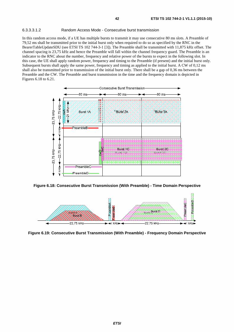
ETSI
ETSI TS 102 744-2-1 V1.1.1 (2015-10) 42
6.3.3.3.1.2 Random Access Mode - Consecutive burst transmission
In this random access mode, if a UE has multiple bursts to transmit it may use consecutive 80 ms slots. A Preamble of 79,52 ms shall be transmitted prior to the initial burst only when required to do so as specified by the RNC in the BearerTableUpdateSDU (see ETSI TS 102 744-3-1 [3]). The Preamble shall be transmitted with 11,875 kHz offset. The channel spacing is 23,75 kHz and hence the Preamble will fall within the channel frequency guard. The Preamble is an indicator to the RNC about the number, frequency and relative power of the bursts to expect in the following slot. In this case, the UE shall apply random power, frequency and timing to the Preamble (if present) and the initial burst only. Subsequent bursts shall apply the same power, frequency and timing as applied to the initial burst. A CW of 0,12 ms shall also be transmitted prior to transmission of the initial burst only. There shall be a gap of 0,36 ms between the Preamble and the CW. The Preamble and burst transmission in the time and the frequency domain is depicted in Figures 6.18 to 6.21.
Figure 6.18: Consecutive Burst Transmission (With Preamble) - Time Domain Perspective
Figure 6.19: Consecutive Burst Transmission (With Preamble) - Frequency Domain Perspective
22,75 kHz
1 kHz
1 kHz
22,75 kHz
23,75 kHz
23,75 kHz
cwA
cwB
21 kHz
cwDc
wC
PreambleA
PreambleB
PreambleD
PreambleC

ETSI
ETSI TS 102 744-2-1 V1.1.1 (2015-10) 43
Figure 6.20: Consecutive Burst Transmission (Without Preamble) - Time Domain Perspective
Figure 6.21: Consecutive Burst Transmission (Without Preamble) - Frequency Domain Perspective
6.3.3.3.1.3 Continuous Access Mode
The Continuous Access Mode, referred to as Shared Reservation Access (SRA) in ETSI TS 102 744-3-2 [4], is identical to Random Access Mode - Consecutive burst transmission specified in clause 6.3.3.3.1.2. The only difference is that the power, frequency and timing offset are signalled and controlled by the RNC. The time domain and frequency domain representation of continuous access mode is illustrated in clause 6.3.3.3.1.2, Figures 6.18 to 6.21.
6.3.3.3.2 R80T1Q-1B
6.3.3.3.2.0 General
The R80T1Q-1B bearer employs 80 ms frame format with the design being similar to R80T0.5Q-1B. The bearer subtypes are specified in clause B.2.
6.3.3.3.2.1 Random Access Mode
The random access mode in case of R80T1Q-1B is similar to R80T0.5Q-1B. If a single burst is transmitted, then each UE shall apply random power, frequency and timing to every slot. A Preamble of 79,52 ms shall be transmitted prior to every burst when required to do so as specified by the RNC in the BearerTableUpdateSDU (see ETSI TS 102 744-3-1 [3]). The Preamble shall be transmitted with 23,75 kHz offset prior to the transmission of each burst. The channel spacing is 47,5 kHz and hence the Preamble will fall within the channel frequency guard. The Preamble is an indicator to the RNC about the number, frequency and relative power of the bursts to expect in the following slot. A CW of 0,12 ms shall also be transmitted prior to the transmission of each data subframe. There shall be a gap of 0,36 ms between the Preamble and the CW. The Preamble and burst transmission in the time and the frequency domain is depicted in Figures 6.22 to 6.25.
Burst 2DBurst 1D
Burst 2BBurst 1B
Burst 2A Burst 3A
Burst 2C
Consecutive Burst Transmission
80 ms 80 ms 80 ms
23,75 kHz
23,75 kHz
Burst 3C
cwA
cwB
cwD
cwC
Burst 1A
21 kHz
Burst 1C
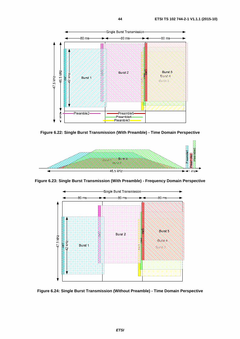
ETSI
ETSI TS 102 744-2-1 V1.1.1 (2015-10) 44
Figure 6.22: Single Burst Transmission (With Preamble) - Time Domain Perspective
Figure 6.23: Single Burst Transmission (With Preamble) - Frequency Domain Perspective
Figure 6.24: Single Burst Transmission (Without Preamble) - Time Domain Perspective
Preamble1
Preamble2
Preamble3
47,5 kHz
cw1
cw3cw4
cw2 c
w5
42 kHz
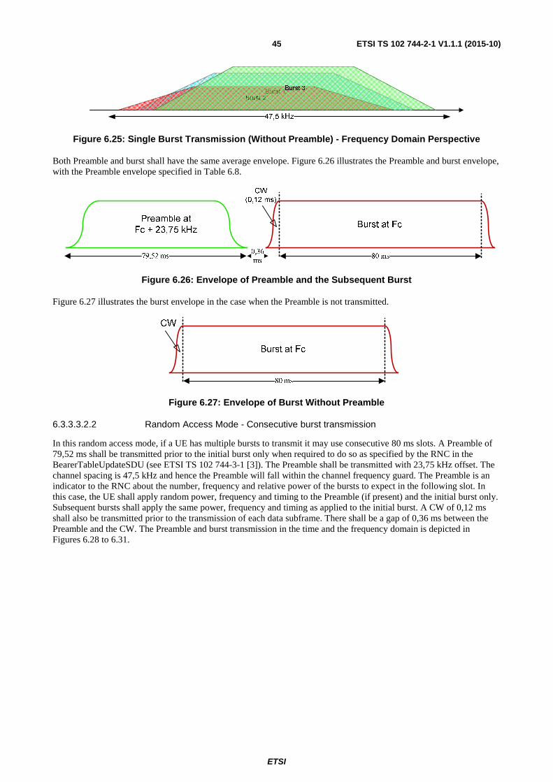
ETSI
ETSI TS 102 744-2-1 V1.1.1 (2015-10) 45
Figure 6.25: Single Burst Transmission (Without Preamble) - Frequency Domain Perspective
Both Preamble and burst shall have the same average envelope. Figure 6.26 illustrates the Preamble and burst envelope, with the Preamble envelope specified in Table 6.8.
Figure 6.26: Envelope of Preamble and the Subsequent Burst
Figure 6.27 illustrates the burst envelope in the case when the Preamble is not transmitted.
Figure 6.27: Envelope of Burst Without Preamble
6.3.3.3.2.2 Random Access Mode - Consecutive burst transmission
In this random access mode, if a UE has multiple bursts to transmit it may use consecutive 80 ms slots. A Preamble of 79,52 ms shall be transmitted prior to the initial burst only when required to do so as specified by the RNC in the BearerTableUpdateSDU (see ETSI TS 102 744-3-1 [3]). The Preamble shall be transmitted with 23,75 kHz offset. The channel spacing is 47,5 kHz and hence the Preamble will fall within the channel frequency guard. The Preamble is an indicator to the RNC about the number, frequency and relative power of the bursts to expect in the following slot. In this case, the UE shall apply random power, frequency and timing to the Preamble (if present) and the initial burst only. Subsequent bursts shall apply the same power, frequency and timing as applied to the initial burst. A CW of 0,12 ms shall also be transmitted prior to the transmission of each data subframe. There shall be a gap of 0,36 ms between the Preamble and the CW. The Preamble and burst transmission in the time and the frequency domain is depicted in Figures 6.28 to 6.31.
Burst at Fc
80 ms
CW

ETSI
ETSI TS 102 744-2-1 V1.1.1 (2015-10) 46
Figure 6.28: Consecutive Burst Transmission (With Preamble) - Time Domain Perspective
Figure 6.29: Consecutive Burst Transmission (With Preamble) - Frequency Domain Perspective
Figure 6.30: Consecutive Burst Transmission (Without Preamble) - Time Domain Perspective
46,5 kHz
1 kHz
47,5 kHz c
wB
cwA
42 kHz
PreambleA
PreambleB

ETSI
ETSI TS 102 744-2-1 V1.1.1 (2015-10) 47
Figure 6.31: Consecutive Burst Transmission (Without Preamble) - Frequency Domain Perspective
6.3.3.3.2.3 Continuous Access Mode
The Continuous Access Mode is identical to Random Access Mode - Consecutive burst transmission specified in clause 6.3.3.3.2.2. The only difference is that the power, frequency and timing offset are signalled and controlled by the RNC. The time domain and frequency domain representation of continuous access mode is illustrated in clause 6.3.3.3.2.2, Figures 6.28 to 6.31.
6.3.3.3.3 Preamble Generation
In the random access mode a single burst is transmitted from each UE with random power, timing and frequency in every slot. In the continuous mode at least one more additional burst is transmitted from the UE following the initial burst. In this case, there is no power, random, frequency and phase offset between the bursts. In all cases, only the initial burst is preceded by a Preamble.
The Preamble shall have "smooth" ramp-up and ramp-down to ensure that no significant interference is generated into the adjacent channels by the Preamble. The symbols are Root Raised Cosine (RRC) filtered with 25 % roll-off. The Preamble shall be amplitude modulated. The Preamble should use the recommended values depicted in Tables 6.7 and 6.8, however some variation is permitted provided that the appropriate power mask (see ETSI TS 102 744-2-2 [2]) is respected.
Table 6.7 : R80T0.5Q-1B - Preamble Envelope
R80T0.5Q-1B Symbol # 0 1 2 3 4 5
Value 0,004278 0,017037 0,03806 0,066987 0,103323 0,146447 Symbol # 6 7 8 9 10 11
Value 0,195619 0,25 0,308658 0,37059 0,434737 0,5 Symbol # 12 13 14 15 16 17
Value 0,565263 0,62941 0,691342 0,75 0,804381 0,853553 Symbol # 18 19 20 21 22 23
Value 0,896677 0,933013 0,96194 0,982963 0,995722 1 Symbol # 24 - 1 312 1 313 1 314 1 315 1 316 1 317
Value 1 0,995722 0,982963 0,96194 0,933013 0,896677 Symbol # 1 318 1 319 1 320 1 321 1 322 1 323
Value 0,853553 0,804381 0,75 0,691342 0,62941 0,565263 Symbol # 1 324 1 325 1 326 1 327 1 328 1 329
Value 0,5 0,434737 0,37059 0,308658 0,25 0,195619 Symbol # 1 330 1 331 1 332 1 333 1 334 1 335
Value 0,146447 0,103323 0,066987 0,03806 0,017037 0,004278
NOTE 1: Table 6.7 depicts the I-channel values, where Q-channel=0.
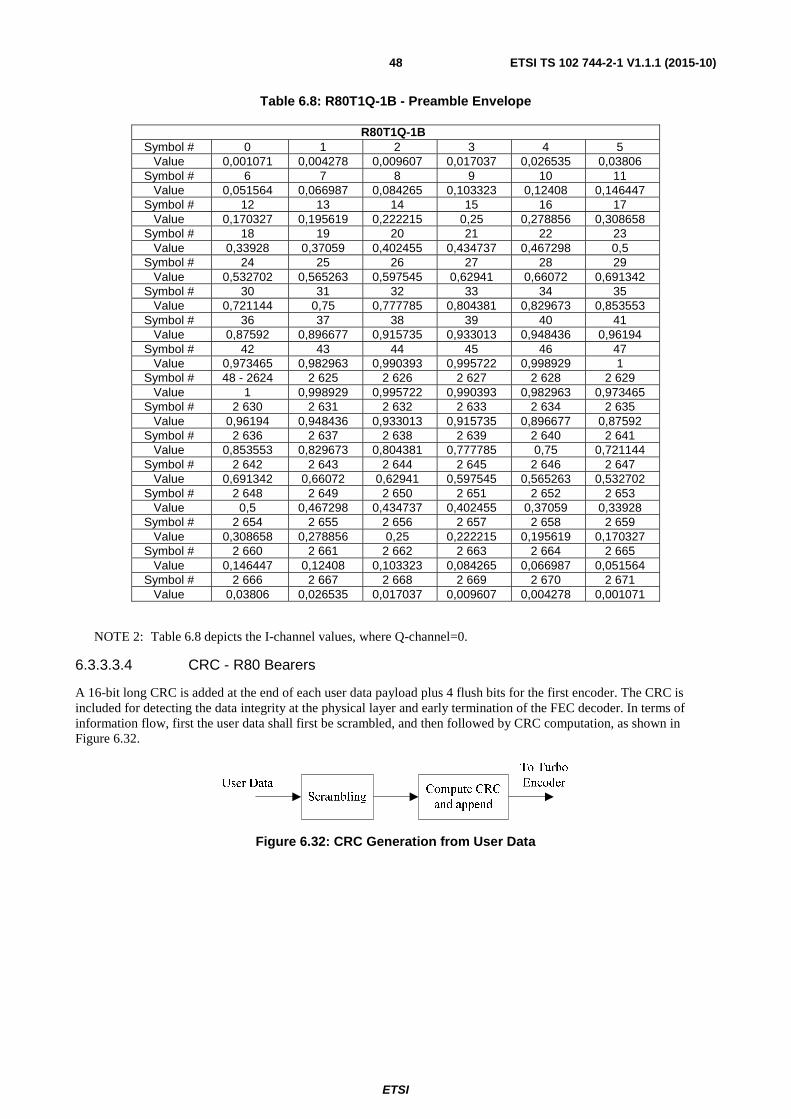
ETSI
ETSI TS 102 744-2-1 V1.1.1 (2015-10) 48
Table 6.8: R80T1Q-1B - Preamble Envelope
R80T1Q-1B Symbol # 0 1 2 3 4 5
Value 0,001071 0,004278 0,009607 0,017037 0,026535 0,03806 Symbol # 6 7 8 9 10 11
Value 0,051564 0,066987 0,084265 0,103323 0,12408 0,146447 Symbol # 12 13 14 15 16 17
Value 0,170327 0,195619 0,222215 0,25 0,278856 0,308658 Symbol # 18 19 20 21 22 23
Value 0,33928 0,37059 0,402455 0,434737 0,467298 0,5 Symbol # 24 25 26 27 28 29
Value 0,532702 0,565263 0,597545 0,62941 0,66072 0,691342 Symbol # 30 31 32 33 34 35
Value 0,721144 0,75 0,777785 0,804381 0,829673 0,853553 Symbol # 36 37 38 39 40 41
Value 0,87592 0,896677 0,915735 0,933013 0,948436 0,96194 Symbol # 42 43 44 45 46 47
Value 0,973465 0,982963 0,990393 0,995722 0,998929 1 Symbol # 48 - 2624 2 625 2 626 2 627 2 628 2 629
Value 1 0,998929 0,995722 0,990393 0,982963 0,973465 Symbol # 2 630 2 631 2 632 2 633 2 634 2 635
Value 0,96194 0,948436 0,933013 0,915735 0,896677 0,87592 Symbol # 2 636 2 637 2 638 2 639 2 640 2 641
Value 0,853553 0,829673 0,804381 0,777785 0,75 0,721144 Symbol # 2 642 2 643 2 644 2 645 2 646 2 647
Value 0,691342 0,66072 0,62941 0,597545 0,565263 0,532702 Symbol # 2 648 2 649 2 650 2 651 2 652 2 653
Value 0,5 0,467298 0,434737 0,402455 0,37059 0,33928 Symbol # 2 654 2 655 2 656 2 657 2 658 2 659
Value 0,308658 0,278856 0,25 0,222215 0,195619 0,170327 Symbol # 2 660 2 661 2 662 2 663 2 664 2 665
Value 0,146447 0,12408 0,103323 0,084265 0,066987 0,051564 Symbol # 2 666 2 667 2 668 2 669 2 670 2 671
Value 0,03806 0,026535 0,017037 0,009607 0,004278 0,001071
NOTE 2: Table 6.8 depicts the I-channel values, where Q-channel=0.
6.3.3.3.4 CRC - R80 Bearers
A 16-bit long CRC is added at the end of each user data payload plus 4 flush bits for the first encoder. The CRC is included for detecting the data integrity at the physical layer and early termination of the FEC decoder. In terms of information flow, first the user data shall first be scrambled, and then followed by CRC computation, as shown in Figure 6.32.
Figure 6.32: CRC Generation from User Data

ETSI
ETSI TS 102 744-2-1 V1.1.1 (2015-10) 49
The Generator Polynomial X16 + X12 + X5 + 1 as specified in [i.3] clause 2.2.7, shall be used to calculate the CRC. The CRC calculation is illustrated in Figure 6.33.
Figure 6.33: CRC Calculation
On initialization all delay elements are initialized to "1". The user data payload (excluding the 2 CRC octets and 4 flush bits) is then clocked into the shift register, starting with bit 1 of the first octet. After the last bit of the user data payload has been clocked in, the ones complement of the shift register contents forms the CRC which with the flush bits shall be appended to the burst as shown in Table 6.9.
Table 6.9: Mapping of CRC and Flush Bits
(MSB) Bit No (LSB)
8 7 6 5 4 3 2 1
User Data Payload Octet1
(n octets)
(without CRC) Octet n
CRCbit 8
CRCbit 1 Octet n+1
CRC bit 16
CRC bit 9 Octet n+2
Flush bit 4
Flush bit 1 Octet n+3
The CRC is computed over data octets and does not cover the 4 flush bits. Furthermore, in R80 Bearers the CRC is only present at the FEC block level and not within the BCtPDU.
6.3.4 Distributed Unique Word Burst Format
6.3.4.1 Distributed Unique Word Burst Format - R80 Bearers
A special format has been developed for the R80 bursts that shall be employed for both random access mode as well as continuous access mode. The Pilot Symbols are used as Unique Word and the term can be used interchangeably. The UW therefore shall be distributed within the data and is illustrated in Figure 6.34 for the R80 bearers. The parameters PSS, PIR and PS vary depending on the selection of bearer and the subsequent subtype and are defined in clause B.2 for R80T0.5Q-1B and R80T1Q-1B respectively.

ETSI
ETSI TS 102 744-2-1 V1.1.1 (2015-10) 50
Figure 6.34: Distributed UW Placement for R80 Bearers
Table 6.10 specifies the UWs that shall be used for every FEC block by both R80T0.5Q-1B and R80T1Q-1B return bearers. Depending on the bearer type and coding level applied, all the UWs or a subset of those shall be used. For example, the R80T1Q-1BL14 has total 448 PS per FEC block and hence the complete set of UWs shall be used. For the case of R80T1Q-1BL13, there are 384 PS per FEC block and therefore Octet # 49 - 56 in UW shall be omitted. Similarly the R80T0.5Q-1BL11 has 168 PS and hence only Octet # 1 - 21 shall be utilized and the rest omitted.
Table 6.10: Unique Words for R80 Bearers
Octet Hex 1 E4 2 56 3 4A 4 DA 5 BD 6 BE 7 D8 8 B3 9 EA 10 D2 11 F2 12 F5 13 F4 14 96 15 A6 16 C9 17 11 18 36 19 42 20 8A 21 F9 22 A4 23 2B 24 B1 25 AB 26 D4 27 E3 28 57 29 29 30 9C 31 4C 32 B9 33 D9 34 D1 35 74 36 6A 37 AF 38 7A 39 6E 40 4E 41 04 42 D4

ETSI
ETSI TS 102 744-2-1 V1.1.1 (2015-10) 51
Octet Hex 43 E1 44 1F 45 2D 46 51 47 4B 48 B8 49 BA 50 62 51 B5 52 89 53 6C 54 CD 55 DF 56 A8
6.3.4.2 Distributed Unique Word Burst Format - R5/R20 bearers
A special burst format is used to assist receivers with the tracking of fast fading, which arises from the mobile radio environment. This format shall be applied in the Aeronautical Class UE and the Land-Mobile Class UE for burst transmissions.
In this special burst format, the UW is partitioned in groups of 4, and distributed across the burst. The number of UW symbols and their constellation mapping remains the same, hence only the symbol placement (in time) changes. The UW spreading can be used on any of the return bearers. When a bearer/burst is transmitted with the distributed UW, the bearer suffix "D" is added to the bearer name. Hence, for example, the R20T1Q-1BL8 bearer is designated with R20T1QD-1BL8 if transmitted with a distributed UW pattern and the R20T1X-1BL3 bearer is designated with R20T1XD-1BL3 if transmitted with a distributed UW pattern. The UW bits and the UW bit-to-symbol mapping are listed in clause 6.3.6.1 for QAM bearers and in clause 6.3.6.2 for π/4-QPSK bursts.
The UW symbol group positions are described with an index counted from the last preamble/CW symbol i.e. the first symbol index after the preamble/CW is 0 as illustrated in Figure 6.35. The first group of UW symbols always starts at index 0. The UW symbol group starting indexes are denoted with a,b,c,d, etc.
Figure 6.35: Distributed Unique Word Mapping

ETSI
ETSI TS 102 744-2-1 V1.1.1 (2015-10) 52
The mapping is shown in Table 6.11.
Table 6.11: UW Distribution Table for Aeronautical Class and Land-Mobile Class UEs
Bearer {a,b,c,d,e, … o,p} R20T0.5QD {0,19,46,71,92,106,137,146,167,201,207,247,256,287,311,324} R20T1XD-1B {0,49,72,138,202,234,281,336,392,436,457,527,539,611,652} R20T1QD-1B {0,58,79,139,190,227,244,306,354,392,426,459,516,585,613,652} R5T1XD-1B {0,9,35,42,62,83,102,119,133,148} R20T2XD-1B {0,85,205,269,386,428,581,679,723,870,900,1 001,1 142,1 233,1 308} R20T2QD-1B {0,100,153,227,387,466,529,637,659,793,911,956,1 018,1 134,1 219,1 308} R5T2XD-1B {0,39,52,101,138,151,210,229,273,300} R5T2QD-1B {0,12,37,60,77,89,112,143,164,178,209,221,233,261,272,300} R20T4.5XD {0,107,388,628,752,1 098,1 246,1 449,1 778,1 861,2 037,2 218,2 443,2 818,2 948} R20T4.5QD {0,206,367,611,720,911,1 133,1 464,1 486,1 865,1 880,2 151,2 313,2 462,2 693,2 948} R5T4.5XD {0,82,113,244,266,387,481,566,622,680} R5T4.5QD {0,39,101,126,183,242,278,297,363,394,474,508,530,599,617,680}
6.3.5 Burst Preamble (R5/R20 bursts)
For R5 and R20 bursts, a preamble (shown in Figures 6.9 and 6.10 as "CW") comprised of repeated identical symbols is transmitted on every burst.
The length of the preamble for all burst types is 0,12 ms, which equates to between two and 18 symbols depending on the symbol rate.
The preamble symbols are chosen to minimize the power envelope variations during the preamble. The first symbol of the Unique Word (MSB bit) in each burst determines the preamble symbol to be used as follows:
For 16-QAM (X/X16) Bearers:
• If the first UW symbol is (b3,b2,b1,b0) = (1,1,1,1) then symbol (b3,b2,b1,b0) = (1,1,1,0) shall be used as the CW symbols.
• If the first UW symbol is (b3,b2,b1,b0) = (0,1,0,1) then symbol (b3,b2,b1,b0) = (0,1,0,0) shall be used as the CW symbols.
For π/4 QPSK (Q) Bearers:
• The first UW symbol shall be used as the CW symbols.
For R5/R20 bursts, the CW preamble at the beginning of each burst shall not be used for synchronization purposes by receivers but is primarily provided to assist a transmitter with an automatic level control loop to ramp up the transmit power of the signal to the required nominal level utilizing the constant power envelope nature of the short preamble. It should be noted that the transient spectrum requirements of clause 6.2.3 also apply to the CW preamble.
6.3.6 Unique Words
6.3.6.0 General
All bursts include either an initial and final unique word or a distributed unique word in order to assist with frequency, phase, and clock synchronization. The unique words are also used to signal the coding level used in the FEC Block of the particular burst, as the coding level can be changed on a burst-by-burst basis.
For the continuous transmission mode, the Unique Words have been defined in clause 5.3.4. For the burst transmission modes, the unique words are specified as hexadecimal numbers in clauses 6.3.6.1 and 6.3.6.2.
6.3.6.1 QAM (X) Bearers
For 16-QAM Bearers, a '1' bit in a Unique Word is presented as the complex symbol (b3,b2,b1,b0) = (1,1,1,1) which is mapped into a phase of 45°, and a '0' bit (b3,b2,b1,b0) = (0,1,0,1) is mapped to 225°. Consequently, the Unique Word is effectively BPSK modulated. Unique Words are not FEC coded and not scrambled. Therefore, all Unique Words are mapped onto the outermost points of the 16-QAM constellation as shown in Figure 6.36; consequently, they are of higher average power than the burst as a whole.
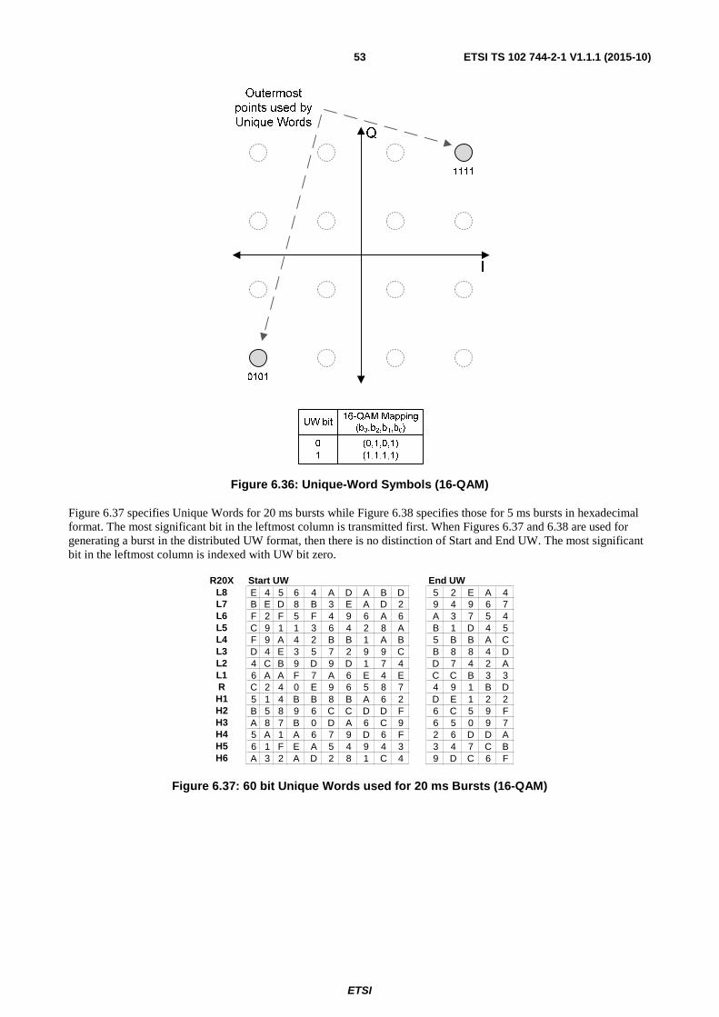
ETSI
ETSI TS 102 744-2-1 V1.1.1 (2015-10) 53
Figure 6.36: Unique-Word Symbols (16-QAM)
Figure 6.37 specifies Unique Words for 20 ms bursts while Figure 6.38 specifies those for 5 ms bursts in hexadecimal format. The most significant bit in the leftmost column is transmitted first. When Figures 6.37 and 6.38 are used for generating a burst in the distributed UW format, then there is no distinction of Start and End UW. The most significant bit in the leftmost column is indexed with UW bit zero.
Figure 6.37: 60 bit Unique Words used for 20 ms Bursts (16-QAM)
R20X Start UW End UWL8 E 4 5 6 4 A D A B D 5 2 E A 4L7 B E D 8 B 3 E A D 2 9 4 9 6 7L6 F 2 F 5 F 4 9 6 A 6 A 3 7 5 4L5 C 9 1 1 3 6 4 2 8 A B 1 D 4 5L4 F 9 A 4 2 B B 1 A B 5 B B A CL3 D 4 E 3 5 7 2 9 9 C B 8 8 4 DL2 4 C B 9 D 9 D 1 7 4 D 7 4 2 AL1 6 A A F 7 A 6 E 4 E C C B 3 3R C 2 4 0 E 9 6 5 8 7 4 9 1 B DH1 5 1 4 B B 8 B A 6 2 D E 1 2 2H2 B 5 8 9 6 C C D D F 6 C 5 9 FH3 A 8 7 B 0 D A 6 C 9 6 5 0 9 7H4 5 A 1 A 6 7 9 D 6 F 2 6 D D AH5 6 1 F E A 5 4 9 4 3 3 4 7 C BH6 A 3 2 A D 2 8 1 C 4 9 D C 6 F

ETSI
ETSI TS 102 744-2-1 V1.1.1 (2015-10) 54
Figure 6.38: Unique Words used for 5 ms Bursts (16-QAM)
6.3.6.2 π/4 QPSK (Q) Bearers
For π/4 QPSK Bearers, a '1' bit in a Unique Word is presented as the complex symbol (b1,b0) = (0,0) that is mapped into a phase of 45°, and a '0' bit (b1,b0) = (1,1) that is mapped to 225°, as shown in Figure 6.39. Consequently, the Unique Word is effectively π/4 BPSK modulated. Unique Words are FEC coded but not scrambled.
Figure 6.39: Unique-Word Symbols (π/4 QPSK)
The π/4 QPSK return bearers uses turbo synchronization, which means that the Unique Word needs to pass through the convolutional encoders as well. The Unique Words are specified in hexadecimal format in Figure 6.40. The most significant bit in the leftmost column is transmitted first.
In order to obtain a 40 bit Start UW and a 24 bit End UW from the 32 bits specified in Figure 6.40, the selected Unique Word is passed to the SRCC encoders before the actual data. The first 8 'p' (un-interleaved) parity bits are appended to the original 32 bits of the selected Unique Word to form the 40 bit long Start UW. The next 24 'p' parity bits are used to form the End UW. This effectively makes the size of the transmitted Unique Word of an π/4 QPSK burst 64 bit. When the 32 bit UW in Figure 6.40 is pushed through the SRCC encoder the actual full UW patterns becomes that of Figure 6.41. This process is specified in more detail in clause 6.3.8.2. When Figure 6.41 is used for generating a burst in the distributed UW format, then there is no distinction of Start and End UW. The most significant bit in the leftmost column is indexed with UW bit zero.
R5X Start UW End UWL8 E 4 5 6 4 A D A B DL7 B E D 8 B 3 E A D 2L6 F 2 F 5 F 4 9 6 A 6L5 C 9 1 1 3 6 4 2 8 AL4 F 9 A 4 2 B B 1 A BL3 D 4 E 3 5 7 2 9 9 CL2 4 C B 9 D 9 D 1 7 4L1 6 A A F 7 A 6 E 4 ER C 2 4 0 E 9 6 5 8 7
H1 5 1 4 B B 8 B A 6 2H2 B 5 8 9 6 C C D D FH3 A 8 7 B 0 D A 6 C 9H4 5 A 1 A 6 7 9 D 6 FH5 6 1 F E A 5 4 9 4 3H6 A 3 2 A D 2 8 1 C 4
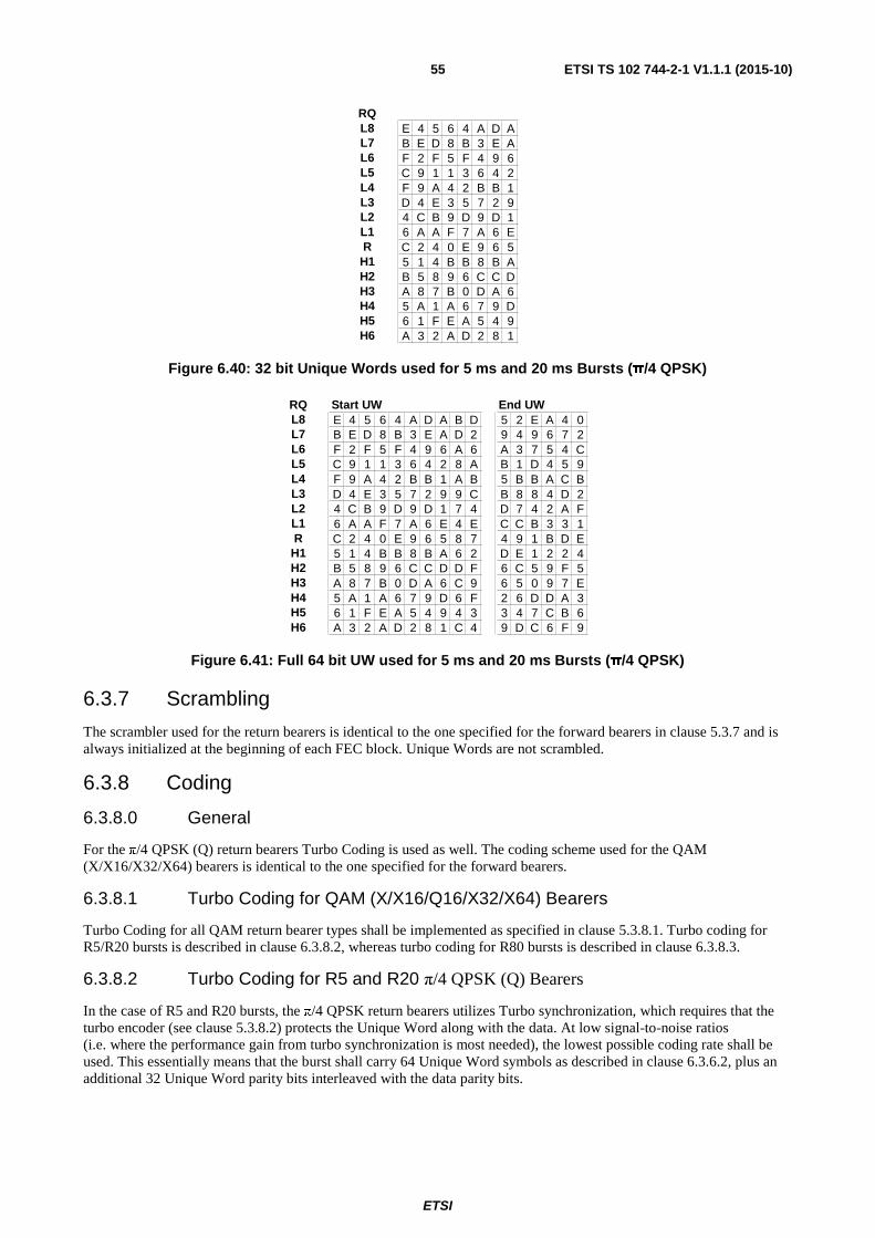
ETSI
ETSI TS 102 744-2-1 V1.1.1 (2015-10) 55
Figure 6.40: 32 bit Unique Words used for 5 ms and 20 ms Bursts (π/4 QPSK)
Figure 6.41: Full 64 bit UW used for 5 ms and 20 ms Bursts (π/4 QPSK)
6.3.7 Scrambling
The scrambler used for the return bearers is identical to the one specified for the forward bearers in clause 5.3.7 and is always initialized at the beginning of each FEC block. Unique Words are not scrambled.
6.3.8 Coding
6.3.8.0 General
For the π/4 QPSK (Q) return bearers Turbo Coding is used as well. The coding scheme used for the QAM (X/X16/X32/X64) bearers is identical to the one specified for the forward bearers.
6.3.8.1 Turbo Coding for QAM (X/X16/Q16/X32/X64) Bearers
Turbo Coding for all QAM return bearer types shall be implemented as specified in clause 5.3.8.1. Turbo coding for R5/R20 bursts is described in clause 6.3.8.2, whereas turbo coding for R80 bursts is described in clause 6.3.8.3.
6.3.8.2 Turbo Coding for R5 and R20 π/4 QPSK (Q) Bearers
In the case of R5 and R20 bursts, the π/4 QPSK return bearers utilizes Turbo synchronization, which requires that the turbo encoder (see clause 5.3.8.2) protects the Unique Word along with the data. At low signal-to-noise ratios (i.e. where the performance gain from turbo synchronization is most needed), the lowest possible coding rate shall be used. This essentially means that the burst shall carry 64 Unique Word symbols as described in clause 6.3.6.2, plus an additional 32 Unique Word parity bits interleaved with the data parity bits.
RQL8 E 4 5 6 4 A D AL7 B E D 8 B 3 E AL6 F 2 F 5 F 4 9 6L5 C 9 1 1 3 6 4 2L4 F 9 A 4 2 B B 1L3 D 4 E 3 5 7 2 9L2 4 C B 9 D 9 D 1L1 6 A A F 7 A 6 ER C 2 4 0 E 9 6 5
H1 5 1 4 B B 8 B AH2 B 5 8 9 6 C C DH3 A 8 7 B 0 D A 6H4 5 A 1 A 6 7 9 DH5 6 1 F E A 5 4 9H6 A 3 2 A D 2 8 1
RQ Start UW End UWL8 E 4 5 6 4 A D A B D 5 2 E A 4 0L7 B E D 8 B 3 E A D 2 9 4 9 6 7 2L6 F 2 F 5 F 4 9 6 A 6 A 3 7 5 4 CL5 C 9 1 1 3 6 4 2 8 A B 1 D 4 5 9L4 F 9 A 4 2 B B 1 A B 5 B B A C BL3 D 4 E 3 5 7 2 9 9 C B 8 8 4 D 2L2 4 C B 9 D 9 D 1 7 4 D 7 4 2 A FL1 6 A A F 7 A 6 E 4 E C C B 3 3 1R C 2 4 0 E 9 6 5 8 7 4 9 1 B D E
H1 5 1 4 B B 8 B A 6 2 D E 1 2 2 4H2 B 5 8 9 6 C C D D F 6 C 5 9 F 5H3 A 8 7 B 0 D A 6 C 9 6 5 0 9 7 EH4 5 A 1 A 6 7 9 D 6 F 2 6 D D A 3H5 6 1 F E A 5 4 9 4 3 3 4 7 C B 6H6 A 3 2 A D 2 8 1 C 4 9 D C 6 F 9

ETSI
ETSI TS 102 744-2-1 V1.1.1 (2015-10) 56
A π/4 QPSK return burst is created as follows:
1) A Unique Word pattern is selected from Figure 6.40 in accordance with the coding level to be used.
2) The data is appended to the selected Unique Word.
3) The Unique Word and data stream 'd' are passed (MSB first) to the convolution encoder.
4) Depending on the end state of the un-interleaved SRCC encoder the 4 flush bits are chosen from Table 5.11.
5) The first 8 'p' (un-punctured) parity bits obtained from the un-interleaved convolutional encoder are appended to the 32 Unique Word bits (as obtained from Figure 6.40) to form the 40 bits of the Start UW at the beginning of the burst. If the burst is to use the distributed UW format then no distinction between start and end UW exist, and the bits shall be distributed in accordance with the procedure described in clause 6.3.4.
6) The next 24 'p' (un-punctured) parity bits obtained from the un-interleaved convolutional encoder are then used as the End UW. If the burst is to use the distributed UW format then no distinction between start and end UW exist, and the bits shall be distributed in accordance with the procedure described in clause 6.3.4.
7) All 'q' parity and the remainder of the 'p' parity bits are punctured and π/4 QPSK modulated along with the data (and flush) bits as specified in clause 6.3.8.3.
The process for the non-distributed UW burst format is illustrated in Figure 6.42.
Figure 6.42: Turbo Encoding of π/4 QPSK Return Burst (Non-Distributed UW)
For more information on Turbo synchronization please see [i.1] and [i.2].
6.3.8.3 Turbo coding for π/4 QPSK (Q) - R80 burst
The R80 bursts are designed for Turbo Code Division Multiple Access (TCDMA) and shall employ low rate FEC based on a Parallel Concatenated Convolutional Code (PCCC) with coding rates from 1/9 to 9/10 approximately obtained by puncturing. Each subtype shall have a different FEC block length which contains a different length user data payload. Therefore, for each burst a separate turbo interleaver and puncturing map is needed. The process is illustrated in Figure 6.43.
The PCCC encoder is similar to the encoder used in all other bearers. The two encoders use the same constraint length, feedback polynomial, both encoders are flushed but only the flush bits of the first encoder are sent. The turbo interleaver is generated using the same algorithm. The main difference between the encoder used for the other bearers and the new encoder is the number and type of feed-forward polynomials, the puncturing maps needed for the exact coding rate generation and the channel interleaver. The feedback polynomial for all coding rates is the 23 in octal. The feed-forward however depends on the coding rate. For R<1/3, the feed-forward polynomials {p1,...,p5} and {q1,...,q5} are {35, 33, 37, 25, 21} in octal. For R>=1/3 the feed-forward polynomials are 35 (as with the encoder used in the other bearers).
The turbo interleaver, state transitions, flush bits, parity bits, puncturing and channel interleaving are all implemented using pre-computed lookup tables and the source code of the described turbo code is included in the same TTP.

ETSI
ETSI TS 102 744-2-1 V1.1.1 (2015-10) 57
Figure 6.43: Extended Turbo Code Encoder for R80 bursts
6.3.8.4 SRCC Encoder
The SRCC Encoder shall be implemented identical to the one used for the forward bearers as specified in clause 5.3.8.2.
6.3.8.5 S-Interleaver
As for the forward channel (see clause 5.3.8.3), the interleaving for the physical layer has been optimized for each return bearer type and sub type. Therefore there are a large number of different interleaver matrices.
The turbo-code interleaver matrices for the return bearers are defined in clause C.1.
6.3.8.6 Puncturing, Channel Interleaving and Symbol Mapping
As for the forward channel (see clause 5.3.8.4), puncturing, channel interleaving and symbol mapping is different and optimized for each return bearer type and sub type. Therefore there are a large number of different matrices.
The puncturing, channel interleaving and symbol mappings for the return bearers are defined in clause C.2.
6.4 PDU Formats PDUs on the return link are grouped into a block structure of variable length depending on the bearer type and subtype being used. The block structure consists of a sequence of Return Bearer Control PDUs (BCt-PDU) followed by padding with zeros, if required, to fill the rest of the FEC block, as defined below and in Table 6.12 and shown in Figure 6.44.
RtnBlock ::= SEQUENCE {
bpduseq SEQUENCE (SIZE (0..k) OF BCt_PDU,
fill OCTET STRING (SIZE (0..n)) OPTIONAL }

ETSI
ETSI TS 102 744-2-1 V1.1.1 (2015-10) 58
Table 6.12: PDU parameters
Parameter Description bpduseq A sequence of between 0 and k variable length Bearer Control PDUs.
Fill Zero padding used to fill out the block (frame is scrambled in channel unit). There may be between 0 and n bytes of pad depending on the overall length and other information in the block.
Figure 6.44: Return block structure
The MSB (Bit 8) of octet 1 goes into the scrambler and FEC encoder first and the LSB (Bit 1) of octet n last.
6.5 Return Channel Timing
6.5.1 Timing Reference
The timing of return channel transmissions is relative to the timing of the forward channel frames. For each forward frame a corresponding return frame is defined, which commences [n × 80 ms + SID] after the beginning of the first symbol of the unique word in the forward frame as observed at the antenna of the UE. The value of n depends on the interleaving used on the forward bearer, i.e. if the interleaving is over a period of 80 ms, then n equals 2, while for shorter interleaving periods (i.e. 10 or 20 ms) n equals 1. The variable SID is the Self Imposed Delay which depends on the physical location of the UE and that of the satellite. Methods for the calculation and maintenance of the SID value are specified in ETSI TS 102 744-3-2 [4].

ETSI
ETSI TS 102 744-2-1 V1.1.1 (2015-10) 59
The relative timing of the forward and return channels is illustrated for n = 1 in Figure 6.45.
Figure 6.45: Relative Timing of Forward and Return Frames referenced to the UE Antenna
The partitioning of the individual tasks and the time required for each task in Figure 6.45 is intended as an illustration only. Actual implementations may vary, but all tasks shall be completed within 80 ms or 160 ms, depending on the value of n.
6.5.2 Return Schedules
Return Schedules (see ETSI TS 102 744-3-1 [3]) are used to allocate return channel resources to UEs. For this purpose, each Return Schedule Signalling Data Unit may contain from one to four Slot Plans, each defining the return channel allocations for an interval of 40 ms (160 ms in the case of R20T0.5Q-1B only). The first Slot Plan in a Return Schedule always defines the return channel allocations in the interval commencing [n × 80 ms + SID] after the start of the FEC block in which the Return Schedule was received.
NOTE: In some cases the interval may be (120 ms + SID). For more details see ETSI TS 102 744-3-2 [4].
If more than one Slot Plan was transmitted in a Return Schedule then these shall define allocations for consecutive 40 ms (160 ms) intervals. The situation illustrated in Figure 6.45 leaves the UE with at least 60 ms from receipt of a FEC block containing a return schedule to the time where the particular return schedule is valid and the UE could potentially have to transmit. The 60 ms shall always be available for the UE as processing time, no matter in which FEC-block the return schedule is located. For more information on return schedules see ETSI TS 102 744-3-2 [4].

ETSI
ETSI TS 102 744-2-1 V1.1.1 (2015-10) 60
6.5.3 Initial Random Access Bearers
For initial random access of UEs to the RNS, the RNS shall allocate a number of consecutive contention slots. The bursts can start in any part of the contention slot. In order to reduce the computational power required for the return demodulator during contention slot processing, the burst types and coding levels for initial random access from UEs are constrained to a sub-set of bearers with only one valid subtype.
Table 6.13 specifies the default bearer types and subtypes for initial random access. The default burst types and coding levels may be changed by the RNS; such changes shall be signalled to all UEs on the forward bearer by means of an AVP (see ETSI TS 102 744-3-1 [3]).
Table 6.13: Random Access Bearers
Bearer Type Identifier Bearer Sub-type
Payload (Octets)
R20T0.5Q-1B & R20T0.5QD L8 21 R5T1X-1B & R5T1XD-1B L1 24 R5T2Q-1B & R5T2QD-1B L8 19
R5T4.5Q-1B & R5T4.5QD-1B L8 51 R80T0.5Q-1B L14 30

ETSI
ETSI TS 102 744-2-1 V1.1.1 (2015-10) 61
Annex A (informative): Bearer Type and Subtype Identifiers
A.1 Bearer type naming conventions To identify the large number of permutations of bearer symbol rate, modulation type, frame/burst duration and coding rate, the formats shown in Tables A.1 and A.2 are used throughout the present document.
Table A.1: Forward Bearer Type Identifier Naming Conventions
Direction Frame Duration
(ms)
Type Symbol Rate (Multiplier x 33,6 kBd)
Modulation FEC Blocks per Frame
F = Forward bearer FR = Bearer used in
both forward and return directions
80 T 0,25 1,0 2,5 4,5 5,0
Q = QPSK X = 16-QAM
X4/16 = 4-QAM/16-QAM X16 = 16-QAM X32 = 32-QAM X64 = 64-QAM
1B 4B 5B 6B 7B 8B 9B
11B 13B
Table A.2: Return Bearer Type Identifier Naming Conventions
Direction Slot Duration
(ms)
Type Symbol Rate (Multiplier x 33,6 kBd)
Modulation Unique Word Pattern
R = Return FR = Bearer used in
both forward and return directions
5 20 80
T 0,5 1,0 2,0 2,5 4,5 5,0
Q = π/4 QPSK X4 = 4-QAM X = 16-QAM
X16 = 16-QAM X32 = 32-QAM X64 = 64-QAM
D = Distributed (For burst transmissions only - see note)
NOTE: Two different Unique Word pattern mappings are used. When the distributed UW pattern is used (DUW, see clause 6.3.4), a "D" suffix is added to the bearer name. Use of the distributed UW applies to burst transmission only.
A given bearer type is identified by taking one element from each column.
As a first example, Bearer Type Identifier F80T0.25Q1B indicates the following properties:
• Forward Bearer
• 80 ms Frame duration
• 0,25 × 33,6 kBd symbol rate
• QPSK modulation
• 1 FEC Block per Frame
As a second example, Bearer Type Identifier R20T4.5XD indicates the following properties:
• Return Bearer
• 20 ms Slot duration
• 4,5 × 33,6 kBd symbol rate
• 16-QAM modulation
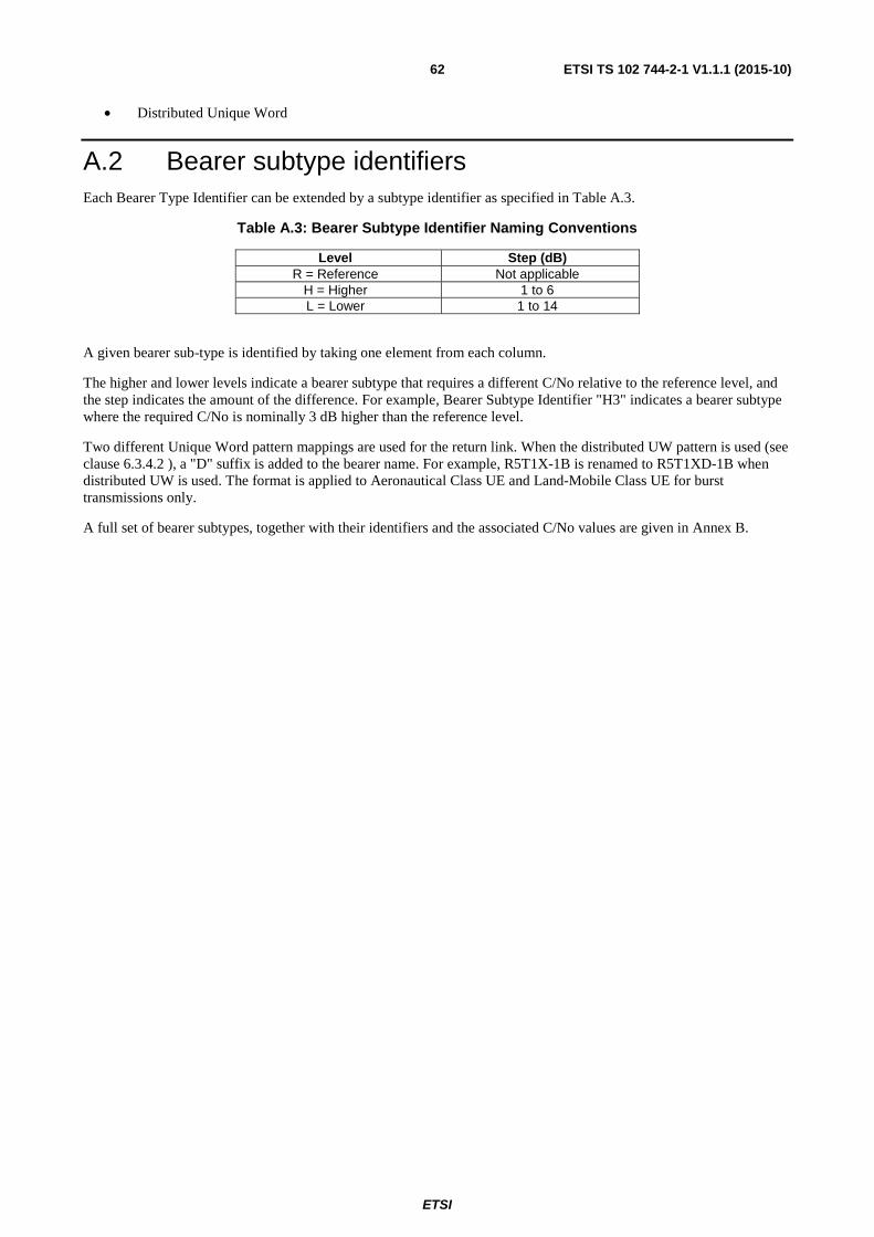
ETSI
ETSI TS 102 744-2-1 V1.1.1 (2015-10) 62
• Distributed Unique Word
A.2 Bearer subtype identifiers Each Bearer Type Identifier can be extended by a subtype identifier as specified in Table A.3.
Table A.3: Bearer Subtype Identifier Naming Conventions
Level Step (dB) R = Reference Not applicable
H = Higher 1 to 6 L = Lower 1 to 14
A given bearer sub-type is identified by taking one element from each column.
The higher and lower levels indicate a bearer subtype that requires a different C/No relative to the reference level, and the step indicates the amount of the difference. For example, Bearer Subtype Identifier "H3" indicates a bearer subtype where the required C/No is nominally 3 dB higher than the reference level.
Two different Unique Word pattern mappings are used for the return link. When the distributed UW pattern is used (see clause 6.3.4.2 ), a "D" suffix is added to the bearer name. For example, R5T1X-1B is renamed to R5T1XD-1B when distributed UW is used. The format is applied to Aeronautical Class UE and Land-Mobile Class UE for burst transmissions only.
A full set of bearer subtypes, together with their identifiers and the associated C/No values are given in Annex B.

ETSI
ETSI TS 102 744-2-1 V1.1.1 (2015-10) 63
Annex B (normative): Bearer parameters
B.1 Forward link bearer parameters Each of the main bearer types listed in clause 5.1 can support a range of bearer sub-types that correspond to different FEC coding rates. The bearer sub-types and associated coding rates are detailed in Table B.1, which is provided as a separate attachment with filename ts_1027440201_AnnexB2_Bearer_Parameters_v010101p0.zip contained in archive ts_1027440201v010101p0.zip which accompanies the present document.
The FR80T2.5X4/16-5B bearer parameters are used for the first and subsequent QPSK modulated FEC blocks within the FR80T2.5X4/16-5B bearer when used with dynamic modulation in the forward direction. The L1 and L2 subtypes are not used in the forward direction during dynamic modulation.
The FR80T2.5X16-5B bearer parameters are used for the 16-QAM modulated FEC blocks within the FR80T2.5X4/16-5B bearer when used with dynamic modulation in the forward direction. The L3 subtype is not used in the forward direction during dynamic modulation.
The FR80T5X4-9B bearer parameters are used for the first and subsequent QPSK modulated FEC blocks within the FR80T5X4/16-9B bearer when used with dynamic modulation in the forward direction. The L1 and L2 subtypes are not used in the forward direction during dynamic modulation.
The FR80T5X16-9B bearer parameters are used for the 16-QAM modulated FEC blocks within the FR80T5X4/16-9B bearer when used with dynamic modulation in the forward direction. The L3 subtype is not used in the forward direction during dynamic modulation.
The C/No values in this table are simulated in an AWGN channel with an ideal modem, i.e. it is only the turbo decoder performance, which is evaluated. The implementation loss on the forward link, which is not included in the C/No values specified in the bearer tables, is estimated to be of the order of 1,0 dB including all degradations from practical non-ideal modems. The C/No values relate to an FEC Block Error Rate of 1×10⁻³. Hence, for bearers containing more than one FEC block per 80 ms frame, the frame error rate is not equal to the FEC Block Error Rate.
Performance of Extension bearers/sub-types are affected adversely by radio wave propagation characteristics such as fading and Doppler. The extent of degradation depends on the mobile environment and modulation/coding.
B.2 Return link bearer parameters Each of the main bearer types listed in clause 6.1 can support a range of bearer sub-types that correspond to different FEC coding rates. The bearer sub-types and associated coding rates are detailed in Table B.2, which is provided as a separate attachment with filename ts_1027440201_AnnexB2_Bearer_Parameters_v010101p0.zip contained in archive ts_1027440201v010101p0.zip which accompanies the present document.
The C/No values for the return link are informative only. The C/No values are simulated in an AWGN channel with ideal modem, i.e. it is only the turbo decoder performance that is evaluated. The implementation loss on the return link, which is not included in the C/No values specified in the bearer tables, is estimated to be of the order of 1,5 dB including all degradations such as HPA non-linearities and non-ideal modems. The C/No values relate to a FEC Block Error Rate of 1×10⁻³.
Turbo frame synchronization on the Q bearers makes the coding rate calculations ambiguous. In the bearer parameter tables the parity bits from the UW are counted in as parity for the data as well. In addition, the UW is treated as data as well. This allows for one coding rate to be calculated, opposed to having two separate coding rates for the UW and data. The "data rate" field does not include the embedded UW bits.

ETSI
ETSI TS 102 744-2-1 V1.1.1 (2015-10) 64
Annex C (normative): Bearer tables
C.1 Turbo-Code Interleaver tables The turbo-code interleaving is optimized for each bearer type and sub type. Therefore there are a large number of different interleaver matrices.
Each interleaving scheme is specified in the form of a table giving the relation between input bits and punctured channel interleaved bits. Due to the large number of different tables, these are not reproduced here but are included as a separate attachment containing a set of text files that describe the mapping between the interleaved data bits and the 'd' (data) bits (see Figure 5.23: Turbo-Encoder Block Diagram). These are provided as a separate attachment with filename ts_1027440201_AnnexC1_v010101p0.zip contained in archive ts_1027440201v010101p0.zip which accompanies the present document.
C.2 Puncturing, Channel Interleaving and Symbol Mapping tables
Puncturing, channel interleaving and symbol mapping is different and optimized for each bearer type and sub type. Therefore there are a large number of different matrices.
Puncturing, channel interleaving and symbol mapping has been specified in the form of tables. Due to the large number of different tables, these are not reproduced here but are included as a separate attachment containing a set of text files that describe the raw bit (d,p and q) to symbol mapping. These are provided as a separate attachment with filename ts_1027440201_AnnexC2_v010101p0.zip contained in archive ts_1027440201v010101p0.zip which accompanies the present document. The files assume the raw bits are arranged in a single zero indexed vector defined as:
{d[0],d[1],d[2],…d[N-1],p[0],p[1],p[2]…,p[Y-1],q[0],q[1],q[2]….,q[T-1]}
Where:
N is the number of 'd' (raw data) bit.
Y is the number of 'p' (non interleaved parity) bit.
T is the number of 'q' (interleaved parity) bit.
ETSI
ETSI TS 102 744-2-1 V1.1.1 (2015-10) 65
History
Document history
V1.1.1 October 2015 Publication